1
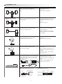
Fiber-optic cable types and characteristics
Cross section
Structure
Unbreakable
(Multi-core)
Features
Effective applications
Compared to conventional regular
fibers:
As easy to install as soft electrical
wiring.
Never have to worry about the
bending radius.
Touching fibers does not affect light
intensity.
Thru scan:
Efficient light transmission at
relatively long scanning
ranges.
Allowable bend radius: 10 or
20 mm.
General use, low cost.
Thru scan:
Excellent bending-resistance
characteristics.
Repeated bending: 1,000,000
times min. (typical example)
Allowable bending radius: 4
mm.
Resists damage when mounted
to moving parts
(Integrated cores)
Regular
(single core)
Bend-tolerant
(bundle)
(separate cores)
Typical models
Bending does not almost
affect light intensity.
Allowable bend radius:1 mm
or 2 mm.
HPF-T025
Diffuse scan:
HPF-D030
HPF-T003
Diffuse scan:
HPF-D002
Thru scan:
HPF-T008
Diffuse scan:
HPF-D037
GLOSSARY
Thru-scan switch
[Principles]
A beam (light) receiver and emitter face each other. An object that
passes between them is detected when the light intensity transmitted
drops because of the object.
Emitter
Receiver
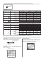
This function and structure uses the characteristics of the reflector
and the polarizing filters built into the polarized-retroreflective
switches to receive only the light reflected from the reflector.
The waveform of the light transmitted through a polarizing filter in
the emitter changes to polarization in a horizontal orientation.
The orientation of the light reflected from the triangular pyramids of
the reflector changes from horizontal to vertical.
This reflected light passes through a polarizing filter in the receiver
to arrive at the receiver.
Longitudinal wave
Vertically
polarizing filter
Reflector
Retroreflective switch
Receiver
An integrated beam (light) emitter-receiver and a reflector face each
other. An object that passes between them is detected when the light
intensity drops because of the object.
Emitter/receiver
Reflector
Emitter
Transvers
wave
Corner cube
Horizontally
polarizing
filter
[Purpose]
This method enables stable detection of targets with a mirrorlike
surface. Light reflected from these types of objects cannot pass
through the polarizing filter on the receiver because the orientation of
polarization is kept horizontal.
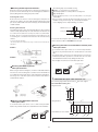
Polarized retroreflective switch
Beam strikes polarizing reflector
This relatively new type of switch solves a problem of conventional
retroreflective switches. Conventional models cannot reliably detect
highly reflective target objects because the beam reflected by the
reflector cannot be distinguished from light reflected by the target
object. However, the use of polarized light allows reliable detection of
highly reflective objects, and is nearly as reliable as thru scan
sensing.
The beam is polarized in the horizontal plane by the emitter. When
the light strikes the reflector, its plane of polarization is rotated 90˚.
Emitter beam
HP100
Reflector
Reflected beam
3