1
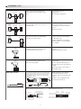
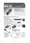
SCANNING TYPE
Type
Principle
Thru scan
Emitter
Target object
Receiver
Retroreflective
Polarized retroreflective
Emitter/
receiver
Target object
Reflector
Diffuse scan
Emitter/
receiver
Target object
Limited diffuse-scan
Emitter/
receiver
Major features
Switch operates when the light between
emitter and receiver is blocked by a target
object.
Long-distance detection.
High accuracy.
A wide range of applications.
Operation is the same as for a thru-scan
switch, but emitter and receiver are housed
in the same unit.
The optical axis can be set easily.
Wiring and installation work are easy
and wiring is necessary for only one
device.
Requires areflection.
Light from the emitter is reflected by the
target object itself. When the reflected light
is detected, the switch operates.
Wiring and installation work are needed
only for switch itself, and installation
requires little space.
Light axis alignment is not required.
Models capable of color discrimination
are available.
Emitter and receiver operate only at a
certain angle. Detection occurs only where
the emitter and receiver axes meet.
Influence of background can be
reduced.
Operation differential is small.
A beam of light strikes the target object,
which is detected by the difference in the
angle of the reflected light.
No interference from high reflectance
backgrounds.
Even if reflectance differs by color or
material, target object can be detected
reliably.
Small target objects can be detected
with high accuracy.
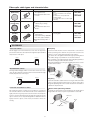
Fiber-optic cable is comprised of a central core with a high refractive
index surrounded by cladding with a low refractive index. Repetitive
total internal reflection at the boundary of the less refractive cladding
guides the light down the fiber-optic cable. The angle of the light
traveling through the fiber-optic cable increases to about 60 by the
time the light exits the fiber.
Highly resistant to noise and other
environmental influences with no
electrical components in the fiber-optic
cable.
Flexible to various applications with
variety of fiber unit line up.
Target object
Background suppression
Emitter/
receiver
Target object
Fiber-optic switches
Refractive index
Cladding Core
sheath
Cladding
Core
Approx.
60˚
LED
Fiber-optic cable
Fiber-optic cable
Light
Target object
Fiber unit
60˚
Emitter
Light
Receiver
Amplifier
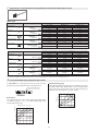
Typical consoles of fiber-optic switches
HPX series potentiometer tuning fiber-optic switches
Sensitivity adjustor (3 turns)
Light indicator (red)
Stability indicator (green)
HPX-AG/EG digital fiber-optic switches
SP (green)
L-ON/D-ON selector
AUTO/OK: Auto tuning button
OFF-Delay switch
Output indicator (orange)
Indicator
2
PV (red)
FUNC/CANCEL:
Function selector
+ button
– button