1
Allen-Bradley
9/Series CNC
Lathe
Operation and
Programming
Manual
Important User Information
Because of the variety of uses for the products described in this publication,
those responsible for the application and use of this control equipment must
satisfy themselves that all necessary steps have been taken to assure that
each application and use meets all performance and safety requirements,
including any applicable laws, regulations, codes and standards.
The illustrations, charts, sample programs and layout examples shown in
this guide are intended solely for purposes of example. Since there are
many variables and requirements associated with any particular installation,
Allen-Bradley does not assume responsibility or liability (to include
intellectual property liability) for actual use based upon the examples shown
in this publication.
Allen-Bradley publication SGI-1.1, Safety Guidelines for the Application,
Installation, and Maintenance of Solid State Control (available from your
local Allen-Bradley office), describes some important differences between
solid-state equipment and electromechanical devices that should be taken
into consideration when applying products such as those described in this
publication.
Reproduction of the contents of this copyrighted publication, in whole or in
part, without written permission of Allen-Bradley Company, Inc. is prohibited.
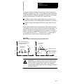
Throughout this manual we make notes to alert you to possible injury to
people or damage to equipment under specific circumstances.
WARNING: Tells readers where people may be hurt if
procedures are not followed properly.
CAUTION: Tells readers where machinery may be damaged or
economic loss can occur if procedures are not followed properly.
Warnings and Cautions:
-
identify a possible trouble spot
tell what causes the trouble
give the result of improper action
tell the reader how to avoid trouble
Important: We recommend that you frequently back up your application
programs on an appropriate storage medium to avoid possible data loss.
PLC is a registered trademark of Allen-Bradley Company, Inc.
Paramacro and PAL are trademarks of Allen-Bradley Company, Inc.
9/Series Lathe
Operation and Programming Manual
October 2000
Summary of Changes
New Information
The following is a list of the larger changes made to this manual since its
last printing. Other less significant changes were also made throughout.
Error Message Log
Paramacro Parameters
Softkey Tree
Error Messages
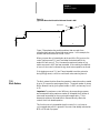
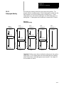
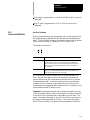
Revision Bars
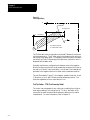
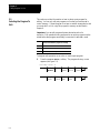
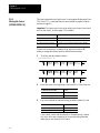
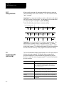
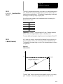
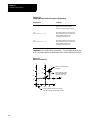
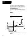
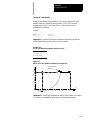
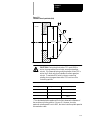
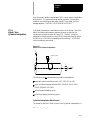
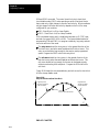
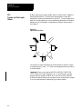
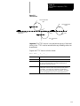
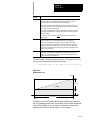
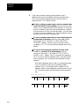
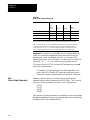
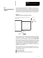
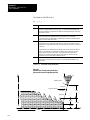
We use revision bars to call your attention to new or revised information.
A revision bar appears as a thick black line on the outside edge of the page
as indicated here.
Chapter
Table
of Contents
Index
(General)
9/Series
Lathe
9/Series
PAL
Reference Manual
Operation and Programming Manual
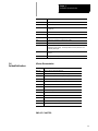
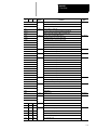
Chapter 1
Using This Manual
1.0 Chapter Overview . . . . . . . . . . . . . . . . . . . . . . . . . . . . . . . . . . . . . . . . . . . . . . . . . . . . . . . . . . . . . .
1.1 Audience . . . . . . . . . . . . . . . . . . . . . . . . . . . . . . . . . . . . . . . . . . . . . . . . . . . . . . . . . . . . . . . . . . . .
1.2 Manual Design . . . . . . . . . . . . . . . . . . . . . . . . . . . . . . . . . . . . . . . . . . . . . . . . . . . . . . . . . . . . . . . .
1.3 Warnings, Cautions, and Important Information . . . . . . . . . . . . . . . . . . . . . . . . . . . . . . . . . . . . . . . . . .
1.4 Reading this Manual . . . . . . . . . . . . . . . . . . . . . . . . . . . . . . . . . . . . . . . . . . . . . . . . . . . . . . . . . . . .
1.5 Terms and Conventions . . . . . . . . . . . . . . . . . . . . . . . . . . . . . . . . . . . . . . . . . . . . . . . . . . . . . . . . . .
1.6 Related Publications . . . . . . . . . . . . . . . . . . . . . . . . . . . . . . . . . . . . . . . . . . . . . . . . . . . . . . . . . . . .
Chapter 2
Basic Control Operation
2.0 Chapter Overview . . . . . . . . . . . . . . . . . . . . . . . . . . . . . . . . . . . . . . . . . . . . . . . . . . . . . . . . . . . . . .
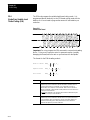
2.1 Operator Panel Operations . . . . . . . . . . . . . . . . . . . . . . . . . . . . . . . . . . . . . . . . . . . . . . . . . . . . . . . .
2.1.1 Keyboard . . . . . . . . . . . . . . . . . . . . . . . . . . . . . . . . . . . . . . . . . . . . . . . . . . . . . . . . . . . . . . . . .
2.1.2 Calculator Function . . . . . . . . . . . . . . . . . . . . . . . . . . . . . . . . . . . . . . . . . . . . . . . . . . . . . . . . . .
2.1.3 Softkeys . . . . . . . . . . . . . . . . . . . . . . . . . . . . . . . . . . . . . . . . . . . . . . . . . . . . . . . . . . . . . . . . . .
2.1.4 CRT . . . . . . . . . . . . . . . . . . . . . . . . . . . . . . . . . . . . . . . . . . . . . . . . . . . . . . . . . . . . . . . . . . . .
2.2 The MTB Panel . . . . . . . . . . . . . . . . . . . . . . . . . . . . . . . . . . . . . . . . . . . . . . . . . . . . . . . . . . . . . . . .
2.3 Software MTB Panel {FRONT PANEL} . . . . . . . . . . . . . . . . . . . . . . . . . . . . . . . . . . . . . . . . . . . . . . . .
2.4 Power Procedures . . . . . . . . . . . . . . . . . . . . . . . . . . . . . . . . . . . . . . . . . . . . . . . . . . . . . . . . . . . . . .
2.4.1 Turning Power On . . . . . . . . . . . . . . . . . . . . . . . . . . . . . . . . . . . . . . . . . . . . . . . . . . . . . . . . . . .
2.4.2 Turning Power OFF . . . . . . . . . . . . . . . . . . . . . . . . . . . . . . . . . . . . . . . . . . . . . . . . . . . . . . . . .
2.5 Control Conditions at Power-Up . . . . . . . . . . . . . . . . . . . . . . . . . . . . . . . . . . . . . . . . . . . . . . . . . . . .
2.6 Emergency Stop Operations . . . . . . . . . . . . . . . . . . . . . . . . . . . . . . . . . . . . . . . . . . . . . . . . . . . . . . .
2.6.1 Emergency Stop Reset . . . . . . . . . . . . . . . . . . . . . . . . . . . . . . . . . . . . . . . . . . . . . . . . . . . . . . .
2.7 Access Control . . . . . . . . . . . . . . . . . . . . . . . . . . . . . . . . . . . . . . . . . . . . . . . . . . . . . . . . . . . . . . . .
2.7.1 Assigning Access Levels and Passwords . . . . . . . . . . . . . . . . . . . . . . . . . . . . . . . . . . . . . . . . . .
2.7.2 Password Protectable Functions . . . . . . . . . . . . . . . . . . . . . . . . . . . . . . . . . . . . . . . . . . . . . . . .
2.7.3 Entering Passwords . . . . . . . . . . . . . . . . . . . . . . . . . . . . . . . . . . . . . . . . . . . . . . . . . . . . . . . . .
2.8 Changing Operating Modes . . . . . . . . . . . . . . . . . . . . . . . . . . . . . . . . . . . . . . . . . . . . . . . . . . . . . . .
2.9 Displaying System and Machine Messages . . . . . . . . . . . . . . . . . . . . . . . . . . . . . . . . . . . . . . . . . . . .
2.9.1 Clearing Active Messages {CLEAR ACTIVE} . . . . . . . . . . . . . . . . . . . . . . . . . . . . . . . . . . . . . . . .
2.10 The Input Cursor . . . . . . . . . . . . . . . . . . . . . . . . . . . . . . . . . . . . . . . . . . . . . . . . . . . . . . . . . . . . . .
2.11 {REFORM MEMORY} . . . . . . . . . . . . . . . . . . . . . . . . . . . . . . . . . . . . . . . . . . . . . . . . . . . . . . . . . . .
2.12 Removing an Axis (Axis Detach) . . . . . . . . . . . . . . . . . . . . . . . . . . . . . . . . . . . . . . . . . . . . . . . . . . .
2.13 Time Parts Count Display Feature . . . . . . . . . . . . . . . . . . . . . . . . . . . . . . . . . . . . . . . . . . . . . . . . . .
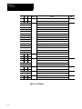
Chapter 3
Offset Tables and Setup
3.0 Chapter Overview . . . . . . . . . . . . . . . . . . . . . . . . . . . . . . . . . . . . . . . . . . . . . . . . . . . . . . . . . . . . . .
3.1 Tool Offset Tables {TOOL GEOMET} and {TOOL WEAR} . . . . . . . . . . . . . . . . . . . . . . . . . . . . . . . . . . .
3.1.1 Tool Dimensional Parameters . . . . . . . . . . . . . . . . . . . . . . . . . . . . . . . . . . . . . . . . . . . . . . . . . .
3.1.2 Tool Orientation Parameters . . . . . . . . . . . . . . . . . . . . . . . . . . . . . . . . . . . . . . . . . . . . . . . . . . .
1-1
1-1
1-1
1-3
1-3
1-4
1-5
2-1
2-1
2-3
2-4
2-8
2-10
2-10
2-13
2-19
2-19
2-20
2-21
2-22
2-22
2-23
2-24
2-27
2-29
2-30
2-34
2-36
2-36
2-37
2-39
2-39
3-1
3-1
3-3
3-6
i
TableIndex
of Contents
(General)
9/Series Lathe
9/Series PAL Reference
Manual
Operation and Programming Manual
3.1.3 Setting Tool Offset Tables . . . . . . . . . . . . . . . . . . . . . . . . . . . . . . . . . . . . . . . . . . . . . . . . . . . . .
3.1.4 Setting Offset Data Using {MEASURE} . . . . . . . . . . . . . . . . . . . . . . . . . . . . . . . . . . . . . . . . . . . .
3.1.5 Tool Offset Range Verification . . . . . . . . . . . . . . . . . . . . . . . . . . . . . . . . . . . . . . . . . . . . . . . . . .
3.2 Changing the Active Tool Offset {ACTIVE OFFSET} . . . . . . . . . . . . . . . . . . . . . . . . . . . . . . . . . . . . . .
3.3 Work Coordinate System Offset Table {WORK CO--ORD} . . . . . . . . . . . . . . . . . . . . . . . . . . . . . . . . . .
3.3.1 Setting Work Coordinate System Data . . . . . . . . . . . . . . . . . . . . . . . . . . . . . . . . . . . . . . . . . . . .
3.4 Backing Up Offset Tables . . . . . . . . . . . . . . . . . . . . . . . . . . . . . . . . . . . . . . . . . . . . . . . . . . . . . . . . .
3.5 Programmable Zone Table . . . . . . . . . . . . . . . . . . . . . . . . . . . . . . . . . . . . . . . . . . . . . . . . . . . . . . . .
3.6 Single--digit Feedrate Table . . . . . . . . . . . . . . . . . . . . . . . . . . . . . . . . . . . . . . . . . . . . . . . . . . . . . . . .
Chapter 4
Manual/MDI Operation Modes
4.0 Chapter Overview . . . . . . . . . . . . . . . . . . . . . . . . . . . . . . . . . . . . . . . . . . . . . . . . . . . . . . . . . . . . . .
4.1 Manual Operating Mode . . . . . . . . . . . . . . . . . . . . . . . . . . . . . . . . . . . . . . . . . . . . . . . . . . . . . . . . . .
4.1.1 Jogging an Axis . . . . . . . . . . . . . . . . . . . . . . . . . . . . . . . . . . . . . . . . . . . . . . . . . . . . . . . . . . . .
4.1.2 Continuous Jog . . . . . . . . . . . . . . . . . . . . . . . . . . . . . . . . . . . . . . . . . . . . . . . . . . . . . . . . . . . .
4.1.3 Incremental Jog . . . . . . . . . . . . . . . . . . . . . . . . . . . . . . . . . . . . . . . . . . . . . . . . . . . . . . . . . . . .
4.1.4 HPG Jog . . . . . . . . . . . . . . . . . . . . . . . . . . . . . . . . . . . . . . . . . . . . . . . . . . . . . . . . . . . . . . . . .
4.1.5 Arbitrary Angle Jog . . . . . . . . . . . . . . . . . . . . . . . . . . . . . . . . . . . . . . . . . . . . . . . . . . . . . . . . . .
4.1.6 Jog Offset . . . . . . . . . . . . . . . . . . . . . . . . . . . . . . . . . . . . . . . . . . . . . . . . . . . . . . . . . . . . . . . .
4.1.7 Resetting Overtravels . . . . . . . . . . . . . . . . . . . . . . . . . . . . . . . . . . . . . . . . . . . . . . . . . . . . . . . .
4.2 Mechanical Handle Feed (Servo Off) . . . . . . . . . . . . . . . . . . . . . . . . . . . . . . . . . . . . . . . . . . . . . . . . .
4.3 Removing an Axis (Axis Detach) . . . . . . . . . . . . . . . . . . . . . . . . . . . . . . . . . . . . . . . . . . . . . . . . . . . .
4.4 Manual Machine Homing . . . . . . . . . . . . . . . . . . . . . . . . . . . . . . . . . . . . . . . . . . . . . . . . . . . . . . . . .
4.5 MDI Mode . . . . . . . . . . . . . . . . . . . . . . . . . . . . . . . . . . . . . . . . . . . . . . . . . . . . . . . . . . . . . . . . . . . .
4.5.1 MDI Basic Operation . . . . . . . . . . . . . . . . . . . . . . . . . . . . . . . . . . . . . . . . . . . . . . . . . . . . . . . . .
Chapter 5
Editing Programs On Line
5.0 Chapter Overview . . . . . . . . . . . . . . . . . . . . . . . . . . . . . . . . . . . . . . . . . . . . . . . . . . . . . . . . . . . . . .
5.1 Selecting the Program To Edit . . . . . . . . . . . . . . . . . . . . . . . . . . . . . . . . . . . . . . . . . . . . . . . . . . . . . .
5.2 Editing Programs at the Control (On Line) . . . . . . . . . . . . . . . . . . . . . . . . . . . . . . . . . . . . . . . . . . . . .
5.2.1 Moving the Cursor {STRING SEARCH} . . . . . . . . . . . . . . . . . . . . . . . . . . . . . . . . . . . . . . . . . . . .
5.2.2 Entering Characters and Blocks . . . . . . . . . . . . . . . . . . . . . . . . . . . . . . . . . . . . . . . . . . . . . . . . .
5.2.3 Changing and Inserting {MODIFY INSERT} . . . . . . . . . . . . . . . . . . . . . . . . . . . . . . . . . . . . . . . . .
5.2.4 Erasing Characters and Blocks . . . . . . . . . . . . . . . . . . . . . . . . . . . . . . . . . . . . . . . . . . . . . . . . .
5.2.5 Sequence Numbers {RENUM PRGRAM} . . . . . . . . . . . . . . . . . . . . . . . . . . . . . . . . . . . . . . . . . . .
5.2.6 Merging Part Programs {MERGE PRGRAM} . . . . . . . . . . . . . . . . . . . . . . . . . . . . . . . . . . . . . . . .
5.2.7 Exiting Edit Mode . . . . . . . . . . . . . . . . . . . . . . . . . . . . . . . . . . . . . . . . . . . . . . . . . . . . . . . . . . .
5.3 Programming Aids {QUICK VIEW} . . . . . . . . . . . . . . . . . . . . . . . . . . . . . . . . . . . . . . . . . . . . . . . . . . .
5.3.1 Using {QPATH+ PROMPT} Sample Patterns . . . . . . . . . . . . . . . . . . . . . . . . . . . . . . . . . . . . . . . .
5.3.2 G-code Format Prompting {G CODE PROMPT} . . . . . . . . . . . . . . . . . . . . . . . . . . . . . . . . . . . . . .
5.3.3 Lathe Cycle Format Prompting . . . . . . . . . . . . . . . . . . . . . . . . . . . . . . . . . . . . . . . . . . . . . . . . .
5.3.4 Drill Cycle Format Prompting . . . . . . . . . . . . . . . . . . . . . . . . . . . . . . . . . . . . . . . . . . . . . . . . . . .
ii
3-8
3-11
3-12
3-14
3-15
3-16
3-19
3-21
3-23
4-1
4-1
4-2
4-3
4-3
4-4
4-5
4-6
4-6
4-7
4-8
4-9
4-11
4-12
5-1
5-2
5-4
5-6
5-7
5-8
5-11
5-14
5-15
5-16
5-16
5-18
5-21
5-23
5-25
Table
of Contents
Index
(General)
9/Series
Lathe
9/Series
PAL
Reference Manual
Operation and Programming Manual
5.3.5 Selecting a QuickView Plane . . . . . . . . . . . . . . . . . . . . . . . . . . . . . . . . . . . . . . . . . . . . . . . . . . .
5.4 Digitizing a Program (Teach) . . . . . . . . . . . . . . . . . . . . . . . . . . . . . . . . . . . . . . . . . . . . . . . . . . . . . . .
5.4.1 Linear Digitizing . . . . . . . . . . . . . . . . . . . . . . . . . . . . . . . . . . . . . . . . . . . . . . . . . . . . . . . . . . . .
5.4.2 Digitizing an Arc (3 Points) . . . . . . . . . . . . . . . . . . . . . . . . . . . . . . . . . . . . . . . . . . . . . . . . . . . . .
5.4.3 Digitizing An Arc Tangent at End Points . . . . . . . . . . . . . . . . . . . . . . . . . . . . . . . . . . . . . . . . . . . .
5.5 Deleting A Program {DELETE} . . . . . . . . . . . . . . . . . . . . . . . . . . . . . . . . . . . . . . . . . . . . . . . . . . . . .
5.6 Renaming Programs {RENAME} . . . . . . . . . . . . . . . . . . . . . . . . . . . . . . . . . . . . . . . . . . . . . . . . . . . .
5.7 Displaying a Program {DISPLY PRGRAM} . . . . . . . . . . . . . . . . . . . . . . . . . . . . . . . . . . . . . . . . . . . . .
5.8 Displaying Comments {COMENT} . . . . . . . . . . . . . . . . . . . . . . . . . . . . . . . . . . . . . . . . . . . . . . . . . . .
5.9 Copying Programs {COPY PRGRAM} . . . . . . . . . . . . . . . . . . . . . . . . . . . . . . . . . . . . . . . . . . . . . . . .
5.10 Selecting the Protectable Part Program Directory . . . . . . . . . . . . . . . . . . . . . . . . . . . . . . . . . . . . . . .
5.10.1 Protected Program Encryption and Decryption . . . . . . . . . . . . . . . . . . . . . . . . . . . . . . . . . . . . . .
5.10.2 Storing Encryption/Decryption Table to Backup Memory . . . . . . . . . . . . . . . . . . . . . . . . . . . . . .
Chapter 6
Editing Part Programs Off Line (ODS)
6.0 Chapter Overview . . . . . . . . . . . . . . . . . . . . . . . . . . . . . . . . . . . . . . . . . . . . . . . . . . . . . . . . . . . . . .
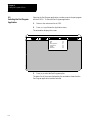
6.1 Selecting the Part Program Application . . . . . . . . . . . . . . . . . . . . . . . . . . . . . . . . . . . . . . . . . . . . . . .
6.2 Editing Part Programs Off Line . . . . . . . . . . . . . . . . . . . . . . . . . . . . . . . . . . . . . . . . . . . . . . . . . . . . .
6.3 Interfacing the Workstation with the Control . . . . . . . . . . . . . . . . . . . . . . . . . . . . . . . . . . . . . . . . . . . .
6.4 Downloading Part Programs from ODS . . . . . . . . . . . . . . . . . . . . . . . . . . . . . . . . . . . . . . . . . . . . . . .
6.5 UPLOAD Part Programs to ODS . . . . . . . . . . . . . . . . . . . . . . . . . . . . . . . . . . . . . . . . . . . . . . . . . . . .
Chapter 7
Running a Program
7.0 Chapter Overview . . . . . . . . . . . . . . . . . . . . . . . . . . . . . . . . . . . . . . . . . . . . . . . . . . . . . . . . . . . . . .
7.1 Selecting Special Running Conditions . . . . . . . . . . . . . . . . . . . . . . . . . . . . . . . . . . . . . . . . . . . . . . . .
7.1.1 Block Delete . . . . . . . . . . . . . . . . . . . . . . . . . . . . . . . . . . . . . . . . . . . . . . . . . . . . . . . . . . . . . . .
7.1.2 Miscellaneous Function Lock . . . . . . . . . . . . . . . . . . . . . . . . . . . . . . . . . . . . . . . . . . . . . . . . . . .
7.1.3 Sequence Stop {SEQ STOP} . . . . . . . . . . . . . . . . . . . . . . . . . . . . . . . . . . . . . . . . . . . . . . . . . . .
7.1.4 Single Block . . . . . . . . . . . . . . . . . . . . . . . . . . . . . . . . . . . . . . . . . . . . . . . . . . . . . . . . . . . . . . .
7.2 Selecting a Part Program Input Device . . . . . . . . . . . . . . . . . . . . . . . . . . . . . . . . . . . . . . . . . . . . . .
7.3 Selecting a Program . . . . . . . . . . . . . . . . . . . . . . . . . . . . . . . . . . . . . . . . . . . . . . . . . . . . . . . . . . . . .
7.4 Deselecting a Part Program . . . . . . . . . . . . . . . . . . . . . . . . . . . . . . . . . . . . . . . . . . . . . . . . . . . . . . .
7.5 Program Search {SEARCH} . . . . . . . . . . . . . . . . . . . . . . . . . . . . . . . . . . . . . . . . . . . . . . . . . . . . . . .
7.6 Search With Recall {MID ST PRGRAM} . . . . . . . . . . . . . . . . . . . . . . . . . . . . . . . . . . . . . . . . . . . . .
7.7 Basic Program Execution . . . . . . . . . . . . . . . . . . . . . . . . . . . . . . . . . . . . . . . . . . . . . . . . . . . . . . . . .
7.7.1 QuickCheck . . . . . . . . . . . . . . . . . . . . . . . . . . . . . . . . . . . . . . . . . . . . . . . . . . . . . . . . . . . . . . .
7.7.2 Axis Inhibit Mode . . . . . . . . . . . . . . . . . . . . . . . . . . . . . . . . . . . . . . . . . . . . . . . . . . . . . . . . . . .
7.7.3 Dry Run Mode . . . . . . . . . . . . . . . . . . . . . . . . . . . . . . . . . . . . . . . . . . . . . . . . . . . . . . . . . . . . .
7.7.4 Part Production/Automatic Mode . . . . . . . . . . . . . . . . . . . . . . . . . . . . . . . . . . . . . . . . . . . . . . . .
7.8 Interrupted Program Recover {RESTRT PRGRAM} . . . . . . . . . . . . . . . . . . . . . . . . . . . . . . . . . . . . . .
7.9 Jog Retract . . . . . . . . . . . . . . . . . . . . . . . . . . . . . . . . . . . . . . . . . . . . . . . . . . . . . . . . . . . . . . . . . . .
7.10 Block Retrace . . . . . . . . . . . . . . . . . . . . . . . . . . . . . . . . . . . . . . . . . . . . . . . . . . . . . . . . . . . . . . . .
5-27
5-28
5-31
5-32
5-34
5-36
5-37
5-38
5-39
5-41
5-42
5-45
5-48
6-1
6-2
6-3
6-6
6-6
6-13
7-1
7-1
7-1
7-2
7-2
7-4
7-5
7-6
7-8
7-9
7-12
7-17
7-18
7-20
7-21
7-23
7-25
7-28
7-31
iii
TableIndex
of Contents
(General)
9/Series Lathe
9/Series PAL Reference
Manual
Operation and Programming Manual
Chapter 8
Display and Graphics
8.0 Chapter Overview . . . . . . . . . . . . . . . . . . . . . . . . . . . . . . . . . . . . . . . . . . . . . . . . . . . . . . . . . . . . . .
8.1 Selection of Axis Position Data Display . . . . . . . . . . . . . . . . . . . . . . . . . . . . . . . . . . . . . . . . . . . . . . .
8.2 PAL Display Page . . . . . . . . . . . . . . . . . . . . . . . . . . . . . . . . . . . . . . . . . . . . . . . . . . . . . . . . . . . . . .
8.3 Changing Languages . . . . . . . . . . . . . . . . . . . . . . . . . . . . . . . . . . . . . . . . . . . . . . . . . . . . . . . . . . . .
8.4 Graphics . . . . . . . . . . . . . . . . . . . . . . . . . . . . . . . . . . . . . . . . . . . . . . . . . . . . . . . . . . . . . . . . . . . .
8.4.1 Selecting the Program for Graphics . . . . . . . . . . . . . . . . . . . . . . . . . . . . . . . . . . . . . . . . . . . . . .
8.4.2 Running Graphics . . . . . . . . . . . . . . . . . . . . . . . . . . . . . . . . . . . . . . . . . . . . . . . . . . . . . . . . . . .
8.4.3 Disabling Graphics . . . . . . . . . . . . . . . . . . . . . . . . . . . . . . . . . . . . . . . . . . . . . . . . . . . . . . . . . .
8.4.4 Changing Parameters . . . . . . . . . . . . . . . . . . . . . . . . . . . . . . . . . . . . . . . . . . . . . . . . . . . . . . . .
8.4.5 Graphics in Single-Block . . . . . . . . . . . . . . . . . . . . . . . . . . . . . . . . . . . . . . . . . . . . . . . . . . . . . .
8.4.6 Clearing Graphics Screen . . . . . . . . . . . . . . . . . . . . . . . . . . . . . . . . . . . . . . . . . . . . . . . . . . . . .
8.4.7 Displaying Machine Information in Graphics . . . . . . . . . . . . . . . . . . . . . . . . . . . . . . . . . . . . . . . .
8.4.8 Zooming Graphics . . . . . . . . . . . . . . . . . . . . . . . . . . . . . . . . . . . . . . . . . . . . . . . . . . . . . . . . . .
8.6 Power Turn-on Screen . . . . . . . . . . . . . . . . . . . . . . . . . . . . . . . . . . . . . . . . . . . . . . . . . . . . . . . . . . .
8.7 Screen Saver . . . . . . . . . . . . . . . . . . . . . . . . . . . . . . . . . . . . . . . . . . . . . . . . . . . . . . . . . . . . . . . . .
Chapter 9
Communications
9.0 Chapter Overview . . . . . . . . . . . . . . . . . . . . . . . . . . . . . . . . . . . . . . . . . . . . . . . . . . . . . . . . . . . . . .
9.1 Setting Communications . . . . . . . . . . . . . . . . . . . . . . . . . . . . . . . . . . . . . . . . . . . . . . . . . . . . . . . . . .
9.1.1 Setting Communication Port Parameter Values . . . . . . . . . . . . . . . . . . . . . . . . . . . . . . . . . . . . . .
9.1.2 Communication Port Parameters . . . . . . . . . . . . . . . . . . . . . . . . . . . . . . . . . . . . . . . . . . . . . . . .
9.2 Inputting Part Programs from a Tape Reader . . . . . . . . . . . . . . . . . . . . . . . . . . . . . . . . . . . . . . . . . . .
9.3 Outputting Part Programs to a Tape Punch . . . . . . . . . . . . . . . . . . . . . . . . . . . . . . . . . . . . . . . . . . . . .
9.4 Verifying Part Programs Against Source Programs . . . . . . . . . . . . . . . . . . . . . . . . . . . . . . . . . . . . . . .
9.5 Error Conditions (Inputting and Outputting Part Programs) . . . . . . . . . . . . . . . . . . . . . . . . . . . . . . . . . .
Chapter 10
Introduction to Programming
10.0 Chapter Overview . . . . . . . . . . . . . . . . . . . . . . . . . . . . . . . . . . . . . . . . . . . . . . . . . . . . . . . . . . . . .
10.1 Tape Format . . . . . . . . . . . . . . . . . . . . . . . . . . . . . . . . . . . . . . . . . . . . . . . . . . . . . . . . . . . . . . . . .
10.2 Program Configuration . . . . . . . . . . . . . . . . . . . . . . . . . . . . . . . . . . . . . . . . . . . . . . . . . . . . . . . . . .
10.2.1 Program Names . . . . . . . . . . . . . . . . . . . . . . . . . . . . . . . . . . . . . . . . . . . . . . . . . . . . . . . . . . .
10.2.2 Sequence Numbers . . . . . . . . . . . . . . . . . . . . . . . . . . . . . . . . . . . . . . . . . . . . . . . . . . . . . . . .
10.2.3 Comment Blocks . . . . . . . . . . . . . . . . . . . . . . . . . . . . . . . . . . . . . . . . . . . . . . . . . . . . . . . . . . .
10.2.4 Block Delete and Multi Level Delete . . . . . . . . . . . . . . . . . . . . . . . . . . . . . . . . . . . . . . . . . . . . .
10.2.5 End of Block Statement . . . . . . . . . . . . . . . . . . . . . . . . . . . . . . . . . . . . . . . . . . . . . . . . . . . . . .
10.3 Using Subprograms . . . . . . . . . . . . . . . . . . . . . . . . . . . . . . . . . . . . . . . . . . . . . . . . . . . . . . . . . . . .
10.3.1 Subprogram Call (M98) . . . . . . . . . . . . . . . . . . . . . . . . . . . . . . . . . . . . . . . . . . . . . . . . . . . . . .
10.3.2 Main and Subprogram Return (M99) . . . . . . . . . . . . . . . . . . . . . . . . . . . . . . . . . . . . . . . . . . . . .
10.3.3 Subprogram Nesting . . . . . . . . . . . . . . . . . . . . . . . . . . . . . . . . . . . . . . . . . . . . . . . . . . . . . . . .
10.4 Word Formats and Functions . . . . . . . . . . . . . . . . . . . . . . . . . . . . . . . . . . . . . . . . . . . . . . . . . . . . .
iv
8-1
8-1
8-22
8-23
8-24
8-24
8-25
8-27
8-27
8-33
8-33
8-33
8-33
8-37
8-38
9-1
9-1
9-1
9-3
9-9
9-13
9-17
9-18
10-1
10-1
10-6
10-8
10-9
10-9
10-10
10-11
10-11
10-12
10-13
10-15
10-16
Table
of Contents
Index
(General)
9/Series
Lathe
9/Series
PAL
Reference Manual
Operation and Programming Manual
10.4.1 Leading Zero and Trailing Zero Suppression . . . . . . . . . . . . . . . . . . . . . . . . . . . . . . . . . . . . . . .
10.4.2 Programming without Numeric Values . . . . . . . . . . . . . . . . . . . . . . . . . . . . . . . . . . . . . . . . . . . .
10.4.3 Word Descriptions and Ranges . . . . . . . . . . . . . . . . . . . . . . . . . . . . . . . . . . . . . . . . . . . . . . . .
10.4.4 Minimum and Maximum Axis Motion (Programming Resolution) . . . . . . . . . . . . . . . . . . . . . . . . .
10.5 Word Descriptions . . . . . . . . . . . . . . . . . . . . . . . . . . . . . . . . . . . . . . . . . . . . . . . . . . . . . . . . . . . . .
10.5.1 Axis Names . . . . . . . . . . . . . . . . . . . . . . . . . . . . . . . . . . . . . . . . . . . . . . . . . . . . . . . . . . . . . .
10.5.2 A_L_,R_,C_ (QuickPath Plus Words) . . . . . . . . . . . . . . . . . . . . . . . . . . . . . . . . . . . . . . . . . . . . .
10.5.3 F-Words (Feedrate) . . . . . . . . . . . . . . . . . . . . . . . . . . . . . . . . . . . . . . . . . . . . . . . . . . . . . . . . .
10.5.4 G-Codes (Preparatory Functions) . . . . . . . . . . . . . . . . . . . . . . . . . . . . . . . . . . . . . . . . . . . . . . .
10.5.5 I J K Integrand Words . . . . . . . . . . . . . . . . . . . . . . . . . . . . . . . . . . . . . . . . . . . . . . . . . . . . . . .
10.5.6 M-Codes (Miscellaneous Functions) . . . . . . . . . . . . . . . . . . . . . . . . . . . . . . . . . . . . . . . . . . . . .
10.5.7 2nd Miscellaneous Function (B-Word) . . . . . . . . . . . . . . . . . . . . . . . . . . . . . . . . . . . . . . . . . . . .
10.5.8 N-Words (Sequence Numbers) . . . . . . . . . . . . . . . . . . . . . . . . . . . . . . . . . . . . . . . . . . . . . . . . .
10.5.9 O-Words (Program Names) . . . . . . . . . . . . . . . . . . . . . . . . . . . . . . . . . . . . . . . . . . . . . . . . . . .
10.5.10 P,L Words (Main Program Jumps and Subprogram Calls) . . . . . . . . . . . . . . . . . . . . . . . . . . . . .
10.5.11 S-Words (Spindle Speed) . . . . . . . . . . . . . . . . . . . . . . . . . . . . . . . . . . . . . . . . . . . . . . . . . . . .
10.5.12 T-Words (Tool Selection and Tool Length Offset) . . . . . . . . . . . . . . . . . . . . . . . . . . . . . . . . . . . .
Chapter 11
Coordinate System Offsets
11.0 Chapter Overview . . . . . . . . . . . . . . . . . . . . . . . . . . . . . . . . . . . . . . . . . . . . . . . . . . . . . . . . . . . . .
11.1 Machine (Absolute) Coordinate System . . . . . . . . . . . . . . . . . . . . . . . . . . . . . . . . . . . . . . . . . . . . . .
11.1.1 Motion in the Machine Coordinate System (G53) . . . . . . . . . . . . . . . . . . . . . . . . . . . . . . . . . . . .
11.2 Preset Work Coordinate Systems (G54-59.3) . . . . . . . . . . . . . . . . . . . . . . . . . . . . . . . . . . . . . . . . . .
11.2.1 Altering Work Coordinate Systems (G10L2) . . . . . . . . . . . . . . . . . . . . . . . . . . . . . . . . . . . . . . . .
11.3 Work Coordinate System External Offset . . . . . . . . . . . . . . . . . . . . . . . . . . . . . . . . . . . . . . . . . . . . .
11.3.1 Altering External Offset (G10L2) . . . . . . . . . . . . . . . . . . . . . . . . . . . . . . . . . . . . . . . . . . . . . . . .
11.4 Offsetting the Work Coordinate Systems . . . . . . . . . . . . . . . . . . . . . . . . . . . . . . . . . . . . . . . . . . . . . .
11.4.1 Coordinate Offset Using Tool Position (G92) . . . . . . . . . . . . . . . . . . . . . . . . . . . . . . . . . . . . . . .
11.4.2 Offsetting Coordinate Zero Points (G52) . . . . . . . . . . . . . . . . . . . . . . . . . . . . . . . . . . . . . . . . . .
11.4.3 {SET ZERO} Offset . . . . . . . . . . . . . . . . . . . . . . . . . . . . . . . . . . . . . . . . . . . . . . . . . . . . . . . . .
11.4.4 Jog Offset . . . . . . . . . . . . . . . . . . . . . . . . . . . . . . . . . . . . . . . . . . . . . . . . . . . . . . . . . . . . . . . .
11.4.5 Canceling Coordinate System Offsets (G92.1) . . . . . . . . . . . . . . . . . . . . . . . . . . . . . . . . . . . . . .
11.4.6 Canceling Selected Coordinate System Offsets (G92.2) . . . . . . . . . . . . . . . . . . . . . . . . . . . . .
11.5 PAL Offsets . . . . . . . . . . . . . . . . . . . . . . . . . . . . . . . . . . . . . . . . . . . . . . . . . . . . . . . . . . . . . . . . . .
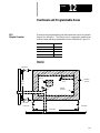
Chapter 12
Overtravels and Programmable Zones
12.0 Chapter Overview . . . . . . . . . . . . . . . . . . . . . . . . . . . . . . . . . . . . . . . . . . . . . . . . . . . . . . . . . . . . .
12.1 Hardware Overtravels . . . . . . . . . . . . . . . . . . . . . . . . . . . . . . . . . . . . . . . . . . . . . . . . . . . . . . . . . .
12.2 Software Overtravels . . . . . . . . . . . . . . . . . . . . . . . . . . . . . . . . . . . . . . . . . . . . . . . . . . . . . . . . . . .
12.3 Programmable Zone 2 . . . . . . . . . . . . . . . . . . . . . . . . . . . . . . . . . . . . . . . . . . . . . . . . . . . . . . . . . .
12.4 Programmable Zone 3 . . . . . . . . . . . . . . . . . . . . . . . . . . . . . . . . . . . . . . . . . . . . . . . . . . . . . . . . . .
12.5 Resetting Overtravels . . . . . . . . . . . . . . . . . . . . . . . . . . . . . . . . . . . . . . . . . . . . . . . . . . . . . . . . . . .
10-16
10-18
10-18
10-20
10-20
10-20
10-21
10-21
10-22
10-27
10-27
10-33
10-33
10-34
10-34
10-34
10-36
11-1
11-1
11-3
11-4
11-7
11-10
11-11
11-13
11-13
11-17
11-18
11-19
11-20
11-21
11-22
12-1
12-2
12-3
12-5
12-7
12-13
v
TableIndex
of Contents
(General)
9/Series Lathe
9/Series PAL Reference
Manual
Operation and Programming Manual
Chapter 13
Coordinate Control
13.0 Chapter Overview . . . . . . . . . . . . . . . . . . . . . . . . . . . . . . . . . . . . . . . . . . . . . . . . . . . . . . . . . . . . .
13.1 Plane Selection (G17, G18, G19) . . . . . . . . . . . . . . . . . . . . . . . . . . . . . . . . . . . . . . . . . . . . . . . . . . .
13.2 Absolute/Incremental Modes (G90, G91) . . . . . . . . . . . . . . . . . . . . . . . . . . . . . . . . . . . . . . . . . . . . .
13.3 Inch/Metric Modes (G70, G71) . . . . . . . . . . . . . . . . . . . . . . . . . . . . . . . . . . . . . . . . . . . . . . . . . . . .
13.4 Radius/Diameter Modes (G07, G08) . . . . . . . . . . . . . . . . . . . . . . . . . . . . . . . . . . . . . . . . . . . . . . . .
13.5 Scaling . . . . . . . . . . . . . . . . . . . . . . . . . . . . . . . . . . . . . . . . . . . . . . . . . . . . . . . . . . . . . . . . . . . . .
13.5.1 Scaling and Axis Position Display Screens . . . . . . . . . . . . . . . . . . . . . . . . . . . . . . . . . . . . . . .
13.5.2 Scaling Magnification Data Screen . . . . . . . . . . . . . . . . . . . . . . . . . . . . . . . . . . . . . . . . . . . . . .
13.5.3 Scaling Restrictions . . . . . . . . . . . . . . . . . . . . . . . . . . . . . . . . . . . . . . . . . . . . . . . . . . . . . . . .
Chapter 14
Axis Motion
14.0 Chapter Overview . . . . . . . . . . . . . . . . . . . . . . . . . . . . . . . . . . . . . . . . . . . . . . . . . . . . . . . . . . . . .
14.1 Positioning Axes . . . . . . . . . . . . . . . . . . . . . . . . . . . . . . . . . . . . . . . . . . . . . . . . . . . . . . . . . . . . . .
14.1.1 Rapid Positioning Mode (G00) . . . . . . . . . . . . . . . . . . . . . . . . . . . . . . . . . . . . . . . . . . . . . . . . .
14.1.2 Linear Interpolation Mode (G01) . . . . . . . . . . . . . . . . . . . . . . . . . . . . . . . . . . . . . . . . . . . . . . . .
14.1.3 Circular Interpolation Mode (G02, G03) . . . . . . . . . . . . . . . . . . . . . . . . . . . . . . . . . . . . . . . . . . .
14.1.4 Positioning Rotary Axes . . . . . . . . . . . . . . . . . . . . . . . . . . . . . . . . . . . . . . . . . . . . . . . . . . . . . .
14.1.5 PAL Axis Mover . . . . . . . . . . . . . . . . . . . . . . . . . . . . . . . . . . . . . . . . . . . . . . . . . . . . . . . . . . .
14.2 Automatic Motion To and From Machine Home . . . . . . . . . . . . . . . . . . . . . . . . . . . . . . . . . . . . . . . . .
14.2.1 Automatic Machine Homing (G28) . . . . . . . . . . . . . . . . . . . . . . . . . . . . . . . . . . . . . . . . . . . . . .
14.2.2 Automatic Return to Machine Home (G28) . . . . . . . . . . . . . . . . . . . . . . . . . . . . . . . . . . . . . . . .
14.2.3 Automatic Return from Machine Home (G29) . . . . . . . . . . . . . . . . . . . . . . . . . . . . . . . . . . . . . . .
14.2.4 Machine Home Return Check (G27) . . . . . . . . . . . . . . . . . . . . . . . . . . . . . . . . . . . . . . . . . . . . .
14.2.5 Move To Alternate Home (G30) . . . . . . . . . . . . . . . . . . . . . . . . . . . . . . . . . . . . . . . . . . . . . . . .
14.3 Dwell (G04) . . . . . . . . . . . . . . . . . . . . . . . . . . . . . . . . . . . . . . . . . . . . . . . . . . . . . . . . . . . . . . . . . .
14.3.1 Dwell - Seconds . . . . . . . . . . . . . . . . . . . . . . . . . . . . . . . . . . . . . . . . . . . . . . . . . . . . . . . . . . .
14.3.2 Dwell - Number of Spindle Revolutions . . . . . . . . . . . . . . . . . . . . . . . . . . . . . . . . . . . . . . . . . . .
14.4 Mirror Image (G50.1, G51.1) . . . . . . . . . . . . . . . . . . . . . . . . . . . . . . . . . . . . . . . . . . . . . . . . . . . . . .
14.5 Axis Clamp . . . . . . . . . . . . . . . . . . . . . . . . . . . . . . . . . . . . . . . . . . . . . . . . . . . . . . . . . . . . . . . . . .
Chapter 15
Using QuickPath Plust
15.0 Chapter Overview . . . . . . . . . . . . . . . . . . . . . . . . . . . . . . . . . . . . . . . . . . . . . . . . . . . . . . . . . . . . .
15.1 Programming QuickPath Plus . . . . . . . . . . . . . . . . . . . . . . . . . . . . . . . . . . . . . . . . . . . . . . . . . . . . .
15.2 Linear QuickPath Plus . . . . . . . . . . . . . . . . . . . . . . . . . . . . . . . . . . . . . . . . . . . . . . . . . . . . . . . . . .
15.3 Circular QuickPath Plus (G13, G13.1) . . . . . . . . . . . . . . . . . . . . . . . . . . . . . . . . . . . . . . . . . . . . . . .
Chapter 16
Chamfering and Corner Radius
16.0 Chapter Overview . . . . . . . . . . . . . . . . . . . . . . . . . . . . . . . . . . . . . . . . . . . . . . . . . . . . . . . . . . . . .
16.1 Chamfering . . . . . . . . . . . . . . . . . . . . . . . . . . . . . . . . . . . . . . . . . . . . . . . . . . . . . . . . . . . . . . . . . .
vi
13-1
13-1
13-2
13-4
13-5
13-7
13-10
13-10
13-12
14-1
14-1
14-1
14-3
14-4
14-9
14-11
14-12
14-12
14-13
14-15
14-16
14-17
14-18
14-18
14-19
14-19
14-22
15-1
15-2
15-3
15-7
16-1
16-2
Table
of Contents
Index
(General)
9/Series
Lathe
9/Series
PAL
Reference Manual
Operation and Programming Manual
16.2 Corner Radius . . . . . . . . . . . . . . . . . . . . . . . . . . . . . . . . . . . . . . . . . . . . . . . . . . . . . . . . . . . . . . . .
16.3 Considerations with Chamfering and Corner Radius . . . . . . . . . . . . . . . . . . . . . . . . . . . . . . . . . . . . .
Chapter 17
Spindles
17.0 Chapter Overview . . . . . . . . . . . . . . . . . . . . . . . . . . . . . . . . . . . . . . . . . . . . . . . . . . . . . . . . . . . . .
17.1 Spindle Speed Control . . . . . . . . . . . . . . . . . . . . . . . . . . . . . . . . . . . . . . . . . . . . . . . . . . . . . . . . . .
17.1.1 Constant Surface Speed Mode (G96) . . . . . . . . . . . . . . . . . . . . . . . . . . . . . . . . . . . . . . . . . . . .
17.1.2 RPM Spindle Speed Mode (G97) . . . . . . . . . . . . . . . . . . . . . . . . . . . . . . . . . . . . . . . . . . . . . . .
17.2 Controlling Spindles (G12.1, G12.2, G12.3) . . . . . . . . . . . . . . . . . . . . . . . . . . . . . . . . . . . . . . . . . . .
17.3 Spindle Orientation (M19, M19.2, M19.3) . . . . . . . . . . . . . . . . . . . . . . . . . . . . . . . . . . . . . . . . . . . . .
17.4 Spindle Direction (M03, M04, M05) . . . . . . . . . . . . . . . . . . . . . . . . . . . . . . . . . . . . . . . . . . . . . . . . .
17.5 Virtual C Axis . . . . . . . . . . . . . . . . . . . . . . . . . . . . . . . . . . . . . . . . . . . . . . . . . . . . . . . . . . . . . . . . .
17.5.1 Virtual C Axis, Cylindrical Interpolation . . . . . . . . . . . . . . . . . . . . . . . . . . . . . . . . . . . . . . . . . . .
17.5.2 Virtual C Axis, End Face Milling . . . . . . . . . . . . . . . . . . . . . . . . . . . . . . . . . . . . . . . . . . . . . . . .
17.6 Synchronized Spindles . . . . . . . . . . . . . . . . . . . . . . . . . . . . . . . . . . . . . . . . . . . . . . . . . . . . . . . . .
17.6.1 Using the Spindle Synchronization Feature . . . . . . . . . . . . . . . . . . . . . . . . . . . . . . . . . . . . . . . .
17.7 Special Considerations for Spindle Synchronization . . . . . . . . . . . . . . . . . . . . . . . . . . . . . . . . . . . . .
Chapter 18
Programming Feedrates
18.0 Chapter Overview . . . . . . . . . . . . . . . . . . . . . . . . . . . . . . . . . . . . . . . . . . . . . . . . . . . . . . . . . . . . .
18.1 Feedrates . . . . . . . . . . . . . . . . . . . . . . . . . . . . . . . . . . . . . . . . . . . . . . . . . . . . . . . . . . . . . . . . . . .
18.1.1 Feedrates Applied During TTRC . . . . . . . . . . . . . . . . . . . . . . . . . . . . . . . . . . . . . . . . . . . . . . . .
18.1.2 Feed Per Minute Mode (G94) . . . . . . . . . . . . . . . . . . . . . . . . . . . . . . . . . . . . . . . . . . . . . . . . . .
18.1.3 Feed Per Revolution Mode (G95) . . . . . . . . . . . . . . . . . . . . . . . . . . . . . . . . . . . . . . . . . . . . . . .
18.1.4 Rapid Feedrate . . . . . . . . . . . . . . . . . . . . . . . . . . . . . . . . . . . . . . . . . . . . . . . . . . . . . . . . . . . .
18.1.5 Feedrate Overrides . . . . . . . . . . . . . . . . . . . . . . . . . . . . . . . . . . . . . . . . . . . . . . . . . . . . . . . . .
18.1.6 Feedrate Limits (Clamp) . . . . . . . . . . . . . . . . . . . . . . . . . . . . . . . . . . . . . . . . . . . . . . . . . . . . .
18.2 Special AMP-assigned Feedrates . . . . . . . . . . . . . . . . . . . . . . . . . . . . . . . . . . . . . . . . . . . . . . . . . .
18.2.1 Single-digit F-words . . . . . . . . . . . . . . . . . . . . . . . . . . . . . . . . . . . . . . . . . . . . . . . . . . . . . . . .
18.2.2 External Deceleration Feedrate Switch . . . . . . . . . . . . . . . . . . . . . . . . . . . . . . . . . . . . . . . . . . .
18.3 Automatic Acceleration/Deceleration . . . . . . . . . . . . . . . . . . . . . . . . . . . . . . . . . . . . . . . . . . . . . . . .
18.3.1 Exponential Acc/Dec . . . . . . . . . . . . . . . . . . . . . . . . . . . . . . . . . . . . . . . . . . . . . . . . . . . . . . . .
18.3.2 Linear Acc/Dec . . . . . . . . . . . . . . . . . . . . . . . . . . . . . . . . . . . . . . . . . . . . . . . . . . . . . . . . . . .
18.3.3 S--Curve Acc/Dec . . . . . . . . . . . . . . . . . . . . . . . . . . . . . . . . . . . . . . . . . . . . . . . . . . . . . . . . . .
18.3.4 Programmable Acc/Dec . . . . . . . . . . . . . . . . . . . . . . . . . . . . . . . . . . . . . . . . . . . . . . . . . . . . .
18.3.5 Precautions on Corner Cutting . . . . . . . . . . . . . . . . . . . . . . . . . . . . . . . . . . . . . . . . . . . . . . . . .
18.3.6 Spindle Acceleration (Ramp) . . . . . . . . . . . . . . . . . . . . . . . . . . . . . . . . . . . . . . . . . . . . . . . . . .
18.3.7 Short Block Acc/Dec Check G36, G36.1 . . . . . . . . . . . . . . . . . . . . . . . . . . . . . . . . . . . . . . . . . .
Chapter 19
Dual Axis Operation
19.0 Chapter Overview . . . . . . . . . . . . . . . . . . . . . . . . . . . . . . . . . . . . . . . . . . . . . . . . . . . . . . . . . . . . .
16-4
16-6
17-1
17-1
17-3
17-9
17-9
17-10
17-12
17-13
17-15
17-20
17-23
17-24
17-27
18-1
18-1
18-2
18-4
18-4
18-6
18-6
18-8
18-8
18-8
18-9
18-10
18-12
18-13
18-14
18-15
18-17
18-19
18-19
19-1
vii
TableIndex
of Contents
(General)
9/Series Lathe
9/Series PAL Reference
Manual
Operation and Programming Manual
19.1 Parking a Dual Axis . . . . . . . . . . . . . . . . . . . . . . . . . . . . . . . . . . . . . . . . . . . . . . . . . . . . . . . . . . . .
19.2 Homing a Dual Axis . . . . . . . . . . . . . . . . . . . . . . . . . . . . . . . . . . . . . . . . . . . . . . . . . . . . . . . . . . . .
19.3 Programming a Dual Axis . . . . . . . . . . . . . . . . . . . . . . . . . . . . . . . . . . . . . . . . . . . . . . . . . . . . . . . .
19.4 Offset Management for a Dual Axis . . . . . . . . . . . . . . . . . . . . . . . . . . . . . . . . . . . . . . . . . . . . . . . . .
Chapter 20
Tool Control Functions
20.0 Chapter Overview . . . . . . . . . . . . . . . . . . . . . . . . . . . . . . . . . . . . . . . . . . . . . . . . . . . . . . . . . . . . .
20.1 T-words and Tool Length Offsets . . . . . . . . . . . . . . . . . . . . . . . . . . . . . . . . . . . . . . . . . . . . . . . . . . .
20.1.1 Programming a T-word and Tool Offsets . . . . . . . . . . . . . . . . . . . . . . . . . . . . . . . . . . . . . . . . . .
20.1.2 Activating Tool Length Offsets . . . . . . . . . . . . . . . . . . . . . . . . . . . . . . . . . . . . . . . . . . . . . . . . .
20.2 Entering Tool Offset Data Using (G10L10, G10L11) . . . . . . . . . . . . . . . . . . . . . . . . . . . . . . . . . . . . . .
20.3 Random Tool . . . . . . . . . . . . . . . . . . . . . . . . . . . . . . . . . . . . . . . . . . . . . . . . . . . . . . . . . . . . . . . . .
20.4 Automatic Tool Life Management . . . . . . . . . . . . . . . . . . . . . . . . . . . . . . . . . . . . . . . . . . . . . . . . . . .
20.4.1 Tool Directory Data . . . . . . . . . . . . . . . . . . . . . . . . . . . . . . . . . . . . . . . . . . . . . . . . . . . . . . . . .
20.4.2 Assigning Detailed Tool Data . . . . . . . . . . . . . . . . . . . . . . . . . . . . . . . . . . . . . . . . . . . . . . . . . .
20.4.3 Programming Data and Backing Up Tool Management Tables (G10L3, G11) . . . . . . . . . . . . . . . .
20.4.4 Programming a T-word Using Tool Management . . . . . . . . . . . . . . . . . . . . . . . . . . . . . . . . . . . .
Chapter 21
Tool Tip Radius Compensation (TTRC) Function
21.0 Chapter Overview . . . . . . . . . . . . . . . . . . . . . . . . . . . . . . . . . . . . . . . . . . . . . . . . . . . . . . . . . . . . .
21.1 Programming TTRC . . . . . . . . . . . . . . . . . . . . . . . . . . . . . . . . . . . . . . . . . . . . . . . . . . . . . . . . . . .
21.2 TTRC Generation Blocks G39, G39.1 . . . . . . . . . . . . . . . . . . . . . . . . . . . . . . . . . . . . . . . . . . . . . . .
21.3 TTRC Tool Paths (Type A) . . . . . . . . . . . . . . . . . . . . . . . . . . . . . . . . . . . . . . . . . . . . . . . . . . . . . . .
21.3.1 TTRC Type A Entry Moves . . . . . . . . . . . . . . . . . . . . . . . . . . . . . . . . . . . . . . . . . . . . . . . . . . .
21.3.2 TTRC Type A Exit Moves . . . . . . . . . . . . . . . . . . . . . . . . . . . . . . . . . . . . . . . . . . . . . . . . . . . .
21.4 TTRC Tool Paths (Type B) . . . . . . . . . . . . . . . . . . . . . . . . . . . . . . . . . . . . . . . . . . . . . . . . . . . . . . .
21.4.1 TTRC Type B Entry Moves . . . . . . . . . . . . . . . . . . . . . . . . . . . . . . . . . . . . . . . . . . . . . . . . . . .
21.4.2 TTRC Type B Exit Moves . . . . . . . . . . . . . . . . . . . . . . . . . . . . . . . . . . . . . . . . . . . . . . . . . . . .
21.5 Tool Path During TTRC . . . . . . . . . . . . . . . . . . . . . . . . . . . . . . . . . . . . . . . . . . . . . . . . . . . . . . . . . .
21.6 TTRC Special Cases . . . . . . . . . . . . . . . . . . . . . . . . . . . . . . . . . . . . . . . . . . . . . . . . . . . . . . . . . . .
21.6.1 Changing TTRC Direction . . . . . . . . . . . . . . . . . . . . . . . . . . . . . . . . . . . . . . . . . . . . . . . . . . . .
21.6.2 Too Many Non-Motion Blocks . . . . . . . . . . . . . . . . . . . . . . . . . . . . . . . . . . . . . . . . . . . . . . . . .
21.6.3 Corner Movement After Generated Blocks . . . . . . . . . . . . . . . . . . . . . . . . . . . . . . . . . . . . . . . .
21.6.4 Changing Cutter Radius During Compensation . . . . . . . . . . . . . . . . . . . . . . . . . . . . . . . . . . . . .
21.6.5 MDI or Manual Motion During TTRC . . . . . . . . . . . . . . . . . . . . . . . . . . . . . . . . . . . . . . . . . . . .
21.6.6 Moving To/From Machine Home . . . . . . . . . . . . . . . . . . . . . . . . . . . . . . . . . . . . . . . . . . . . . . .
21.6.7 Changing or Offsetting Work Coordinate System in TTRC . . . . . . . . . . . . . . . . . . . . . . . . . . . . . .
21.6.8 Block Look-Ahead . . . . . . . . . . . . . . . . . . . . . . . . . . . . . . . . . . . . . . . . . . . . . . . . . . . . . . . . .
21.7 Error Detection . . . . . . . . . . . . . . . . . . . . . . . . . . . . . . . . . . . . . . . . . . . . . . . . . . . . . . . . . . . . . . .
viii
19-3
19-4
19-5
19-7
20-1
20-2
20-3
20-5
20-6
20-7
20-14
20-14
20-19
20-22
20-26
21-1
21-4
21-8
21-10
21-10
21-14
21-20
21-20
21-24
21-30
21-35
21-35
21-39
21-41
21-43
21-47
21-49
21-51
21-52
21-52
Table
of Contents
Index
(General)
9/Series
Lathe
9/Series
PAL
Reference Manual
Operation and Programming Manual
Chapter 22
Single-Pass Turning Cycles
22.0 Chapter Overview . . . . . . . . . . . . . . . . . . . . . . . . . . . . . . . . . . . . . . . . . . . . . . . . . . . . . . . . . . . . .
22.1 Single-pass O.D. and I.D. Roughing Cycle (G20) . . . . . . . . . . . . . . . . . . . . . . . . . . . . . . . . . . . . . . .
22.2 Single-pass Rough Facing Cycle (G24) . . . . . . . . . . . . . . . . . . . . . . . . . . . . . . . . . . . . . . . . . . . . . .
Chapter 23
Grooving/Cutoff Cycles
23.0 Chapter Overview . . . . . . . . . . . . . . . . . . . . . . . . . . . . . . . . . . . . . . . . . . . . . . . . . . . . . . . . . . . . .
23.1 Face Grooving Cycle (G76) . . . . . . . . . . . . . . . . . . . . . . . . . . . . . . . . . . . . . . . . . . . . . . . . . . . . . .
23.2 O.D. & I.D. Grooving Cycle (G77) . . . . . . . . . . . . . . . . . . . . . . . . . . . . . . . . . . . . . . . . . . . . . . . . . .
Chapter 24
Compound Turning Routines
24.0 Chapter Overview . . . . . . . . . . . . . . . . . . . . . . . . . . . . . . . . . . . . . . . . . . . . . . . . . . . . . . . . . . . . .
24.1 O.D. and I.D. Roughing Routine (G73) . . . . . . . . . . . . . . . . . . . . . . . . . . . . . . . . . . . . . . . . . . . . . . .
24.2 Rough Facing Routine (G74) . . . . . . . . . . . . . . . . . . . . . . . . . . . . . . . . . . . . . . . . . . . . . . . . . . . . . .
24.3 Casting/Forging Roughing Routine (G75) . . . . . . . . . . . . . . . . . . . . . . . . . . . . . . . . . . . . . . . . . . . . .
24.4 O.D. and I.D. Finishing Routine (G72) . . . . . . . . . . . . . . . . . . . . . . . . . . . . . . . . . . . . . . . . . . . . . . .
Chapter 25
Thread Cutting
25.0 Chapter Overview . . . . . . . . . . . . . . . . . . . . . . . . . . . . . . . . . . . . . . . . . . . . . . . . . . . . . . . . . . . . .
25.1 Considerations for Thread Cutting . . . . . . . . . . . . . . . . . . . . . . . . . . . . . . . . . . . . . . . . . . . . . . . . . .
25.2 Chamfering Your Threads . . . . . . . . . . . . . . . . . . . . . . . . . . . . . . . . . . . . . . . . . . . . . . . . . . . . . . . .
25.3 Single Pass Threading Mode (G33) . . . . . . . . . . . . . . . . . . . . . . . . . . . . . . . . . . . . . . . . . . . . . . . . .
25.4 Single Pass Variable Lead Thread Cutting (G34) . . . . . . . . . . . . . . . . . . . . . . . . . . . . . . . . . . . . . . . .
25.5 Single Pass Threading Cycle (G21) . . . . . . . . . . . . . . . . . . . . . . . . . . . . . . . . . . . . . . . . . . . . . . . . .
25.6 O.D. & I.D. Multipass Threading Routine (G78) . . . . . . . . . . . . . . . . . . . . . . . . . . . . . . . . . . . . . . . . .
Chapter 26
Drilling Cycles
26.0 Chapter Overview . . . . . . . . . . . . . . . . . . . . . . . . . . . . . . . . . . . . . . . . . . . . . . . . . . . . . . . . . . . . .
26.1 Drilling Cycles . . . . . . . . . . . . . . . . . . . . . . . . . . . . . . . . . . . . . . . . . . . . . . . . . . . . . . . . . . . . . . . .
26.2 Positioning and Hole Machining Axes . . . . . . . . . . . . . . . . . . . . . . . . . . . . . . . . . . . . . . . . . . . . . . .
26.3 Parameters . . . . . . . . . . . . . . . . . . . . . . . . . . . . . . . . . . . . . . . . . . . . . . . . . . . . . . . . . . . . . . . . . .
26.4 Drilling Cycle Operations . . . . . . . . . . . . . . . . . . . . . . . . . . . . . . . . . . . . . . . . . . . . . . . . . . . . . . . .
(G80): Cancel or End Fixed Cycles . . . . . . . . . . . . . . . . . . . . . . . . . . . . . . . . . . . . . . . . . . . . . . . .
(G81): Drilling Cycle, No Dwell/Rapid Out . . . . . . . . . . . . . . . . . . . . . . . . . . . . . . . . . . . . . . . . . . . .
(G82): Drill Cycle, Dwell/Rapid Out . . . . . . . . . . . . . . . . . . . . . . . . . . . . . . . . . . . . . . . . . . . . . . . .
(G83): Deep Hole Drilling Cycle . . . . . . . . . . . . . . . . . . . . . . . . . . . . . . . . . . . . . . . . . . . . . . . . . . .
(G83.1): Deep Hole Peck Drilling Cycle with Dwell . . . . . . . . . . . . . . . . . . . . . . . . . . . . . . . . . . . . . .
(G84): Right-Hand Tapping Cycle . . . . . . . . . . . . . . . . . . . . . . . . . . . . . . . . . . . . . . . . . . . . . . . . .
(G84.1): Left-Hand Tapping Cycle . . . . . . . . . . . . . . . . . . . . . . . . . . . . . . . . . . . . . . . . . . . . . . . . . .
22-1
22-2
22-8
23-1
23-3
23-6
24-1
24-2
24-15
24-29
24-35
25-1
25-2
25-4
25-6
25-12
25-16
25-20
26-1
26-1
26-4
26-7
26-8
26-8
26-9
26-10
26-12
26-13
26-15
26-17
ix
TableIndex
of Contents
(General)
9/Series Lathe
9/Series PAL Reference
Manual
Operation and Programming Manual
(G84.2): Right-Hand Solid-Tapping Cycle . . . . . . . . . . . . . . . . . . . . . . . . . . . . . . . . . . . . . . . . . . . . .
(G84.3): Left-Hand Solid-Tapping Cycle . . . . . . . . . . . . . . . . . . . . . . . . . . . . . . . . . . . . . . . . . . . . . .
(G85):
Boring Cycle, No Dwell/Feed Out . . . . . . . . . . . . . . . . . . . . . . . . . . . . . . . . . . . . . . . . . . . .
(G86):
Boring Cycle, Spindle Stop/Rapid Out . . . . . . . . . . . . . . . . . . . . . . . . . . . . . . . . . . . . . . . . .
(G86.1): Boring Cycle, Tool Shift . . . . . . . . . . . . . . . . . . . . . . . . . . . . . . . . . . . . . . . . . . . . . . . . . .
(G87):
Back Boring Cycle . . . . . . . . . . . . . . . . . . . . . . . . . . . . . . . . . . . . . . . . . . . . . . . . . . . . . .
(G88):
Boring Cycle, Spindle Stop/Manual Out . . . . . . . . . . . . . . . . . . . . . . . . . . . . . . . . . . . . . . . .
(G89):
Boring Cycle, Dwell/Feed Out . . . . . . . . . . . . . . . . . . . . . . . . . . . . . . . . . . . . . . . . . . . . . .
26.5 Altering Drilling Cycle Parameters . . . . . . . . . . . . . . . . . . . . . . . . . . . . . . . . . . . . . . . . . . . . . . . . . .
26.6 Examples of Drilling Cycles . . . . . . . . . . . . . . . . . . . . . . . . . . . . . . . . . . . . . . . . . . . . . . . . . . . . . . .
Chapter 27
Skip and Gauge Probing Cycles
27.0 Chapter Overview . . . . . . . . . . . . . . . . . . . . . . . . . . . . . . . . . . . . . . . . . . . . . . . . . . . . . . . . . . . . .
27.1 External Skip Functions (G31 codes) . . . . . . . . . . . . . . . . . . . . . . . . . . . . . . . . . . . . . . . . . . . . . . . .
27.2 Tool Gauging External Skip Functions (G37 codes) . . . . . . . . . . . . . . . . . . . . . . . . . . . . . . . . . . . . . .
Chapter 28
Paramacros
28.0 Chapter Overview . . . . . . . . . . . . . . . . . . . . . . . . . . . . . . . . . . . . . . . . . . . . . . . . . . . . . . . . . . . . .
28.1 Parametric Expressions . . . . . . . . . . . . . . . . . . . . . . . . . . . . . . . . . . . . . . . . . . . . . . . . . . . . . . . . .
28.1.1 Basic Mathematical Operators . . . . . . . . . . . . . . . . . . . . . . . . . . . . . . . . . . . . . . . . . . . . . . . . .
28.1.2 Mathematical Function Commands . . . . . . . . . . . . . . . . . . . . . . . . . . . . . . . . . . . . . . . . . . . . .
28.1.3 Parametric Expressions as G-- or M--Codes . . . . . . . . . . . . . . . . . . . . . . . . . . . . . . . . . . . . . .
28.2 Transfer of Control Commands . . . . . . . . . . . . . . . . . . . . . . . . . . . . . . . . . . . . . . . . . . . . . . . . . . . .
28.2.1 Conditional Operators . . . . . . . . . . . . . . . . . . . . . . . . . . . . . . . . . . . . . . . . . . . . . . . . . . . . . . .
28.2.2 GOTO and IF-GOTO Commands . . . . . . . . . . . . . . . . . . . . . . . . . . . . . . . . . . . . . . . . . . . . . .
28.2.3 DO-END and WHILE-DO-END Commands . . . . . . . . . . . . . . . . . . . . . . . . . . . . . . . . . . . . . . .
28.3 Parameter Assignments . . . . . . . . . . . . . . . . . . . . . . . . . . . . . . . . . . . . . . . . . . . . . . . . . . . . . . . . .
28.3.1 Local Parameter Assignments . . . . . . . . . . . . . . . . . . . . . . . . . . . . . . . . . . . . . . . . . . . . . . . . .
28.3.2 Common Parameters . . . . . . . . . . . . . . . . . . . . . . . . . . . . . . . . . . . . . . . . . . . . . . . . . . . . . . .
28.3.3 System Parameters . . . . . . . . . . . . . . . . . . . . . . . . . . . . . . . . . . . . . . . . . . . . . . . . . . . . . . . .
28.3.4 PAL Parameters . . . . . . . . . . . . . . . . . . . . . . . . . . . . . . . . . . . . . . . . . . . . . . . . . . . . . . . . . . .
28.3.5 Shared Dual-Process Parameters (#7100 - 7199) . . . . . . . . . . . . . . . . . . . . . . . . . . . . . . . . . . .
28.4 Assigning Parameter Values . . . . . . . . . . . . . . . . . . . . . . . . . . . . . . . . . . . . . . . . . . . . . . . . . . . . .
28.5 Macro Call Commands . . . . . . . . . . . . . . . . . . . . . . . . . . . . . . . . . . . . . . . . . . . . . . . . . . . . . . . . .
28.5.1 Non-Modal Paramacro Call (G65) . . . . . . . . . . . . . . . . . . . . . . . . . . . . . . . . . . . . . . . . . . . . . .
28.5.2 Modal Paramacro Call (G66) . . . . . . . . . . . . . . . . . . . . . . . . . . . . . . . . . . . . . . . . . . . . . . . . . .
28.5.3 Modal Paramacro Call (G66.1) . . . . . . . . . . . . . . . . . . . . . . . . . . . . . . . . . . . . . . . . . . . . . . . .
28.5.4 AMP-defined G-Code Macro Call . . . . . . . . . . . . . . . . . . . . . . . . . . . . . . . . . . . . . . . . . . . . . . .
28.5.5 AMP-Defined M-Code Macro Call . . . . . . . . . . . . . . . . . . . . . . . . . . . . . . . . . . . . . . . . . . . . . .
28.5.6 AMP-Defined T--, S--, and B--Code Macro Call . . . . . . . . . . . . . . . . . . . . . . . . . . . . . . . . . . . . .
28.5.7 Nesting Macros . . . . . . . . . . . . . . . . . . . . . . . . . . . . . . . . . . . . . . . . . . . . . . . . . . . . . . . . . . .
28.6 Macro Output Commands . . . . . . . . . . . . . . . . . . . . . . . . . . . . . . . . . . . . . . . . . . . . . . . . . . . . . . .
x
26-20
26-23
26-25
26-27
26-28
26-31
26-34
26-36
26-38
26-40
27-1
27-2
27-3
28-1
28-2
28-2
28-4
28-6
28-7
28-7
28-8
28-10
28-12
28-12
28-15
28-15
28-31
28-33
28-34
28-42
28-43
28-44
28-46
28-48
28-49
28-49
28-50
28-52
Table
of Contents
Index
(General)
9/Series
Lathe
9/Series
PAL
Reference Manual
Operation and Programming Manual
Chapter 29
Program Interrupt
29.0 Chapter Overview . . . . . . . . . . . . . . . . . . . . . . . . . . . . . . . . . . . . . . . . . . . . . . . . . . . . . . . . . . . . .
29.1 Enabling and Disabling Interrupts (M96/M97) . . . . . . . . . . . . . . . . . . . . . . . . . . . . . . . . . . . . . . . . . .
29.2 Interrupt Request Considerations . . . . . . . . . . . . . . . . . . . . . . . . . . . . . . . . . . . . . . . . . . . . . . . . . .
29.3 Interrupt Types . . . . . . . . . . . . . . . . . . . . . . . . . . . . . . . . . . . . . . . . . . . . . . . . . . . . . . . . . . . . . . .
29.4 The Interrupt Program . . . . . . . . . . . . . . . . . . . . . . . . . . . . . . . . . . . . . . . . . . . . . . . . . . . . . . . . . .
Chapter 30
Using a 9/Series Dual-Processing System
30.0 Chapter Overview . . . . . . . . . . . . . . . . . . . . . . . . . . . . . . . . . . . . . . . . . . . . . . . . . . . . . . . . . . . . .
30.1 Defining of a Dual-Processing System . . . . . . . . . . . . . . . . . . . . . . . . . . . . . . . . . . . . . . . . . . . . . . .
30.2 Operating a Dual-Processing System . . . . . . . . . . . . . . . . . . . . . . . . . . . . . . . . . . . . . . . . . . . . . . . .
30.3 Synchronizing Multiple Part Programs . . . . . . . . . . . . . . . . . . . . . . . . . . . . . . . . . . . . . . . . . . . . . . .
30.4 Spindle Control for Dual--Processing Systems . . . . . . . . . . . . . . . . . . . . . . . . . . . . . . . . . . . . . . . . .
30.4.1 Shared Spindle Configurations . . . . . . . . . . . . . . . . . . . . . . . . . . . . . . . . . . . . . . . . . . . . . . . . .
30.4.2 Separate Spindle Configuration . . . . . . . . . . . . . . . . . . . . . . . . . . . . . . . . . . . . . . . . . . . . . . . .
30.5 Using Interference Checking with a Dual-Process Lathe . . . . . . . . . . . . . . . . . . . . . . . . . . . . . . . . . .
30.5.1 Measuring Interference Boundaries . . . . . . . . . . . . . . . . . . . . . . . . . . . . . . . . . . . . . . . . . . . . .
30.5.2 Entering Interference Values Manually . . . . . . . . . . . . . . . . . . . . . . . . . . . . . . . . . . . . . . . . . . .
30.5.3 Entering Interference Values through Programming (G10L5 and G10L6) . . . . . . . . . . . . . . . . . . .
30.5.4 Backing Up Interference Tables . . . . . . . . . . . . . . . . . . . . . . . . . . . . . . . . . . . . . . . . . . . . . . . .
30.6 Shared Axes on Dual--Processing Systems . . . . . . . . . . . . . . . . . . . . . . . . . . . . . . . . . . . . . . . . . . .
30.6.1 Operating a Shared Axis . . . . . . . . . . . . . . . . . . . . . . . . . . . . . . . . . . . . . . . . . . . . . . . . . . . . .
30.6.2 Switching a Shared Axis to a Different Process . . . . . . . . . . . . . . . . . . . . . . . . . . . . . . . . . . . . .
30.6.3 Setting up a Shared Axis . . . . . . . . . . . . . . . . . . . . . . . . . . . . . . . . . . . . . . . . . . . . . . . . . . . . .
30.7 Dual--Axes on a Dual--Processing System . . . . . . . . . . . . . . . . . . . . . . . . . . . . . . . . . . . . . . . . . . . .
30.7.1 Decoupling a Dual--Axis Group . . . . . . . . . . . . . . . . . . . . . . . . . . . . . . . . . . . . . . . . . . . . . .
30.7.2 Independently Programming Dual--Axis Members . . . . . . . . . . . . . . . . . . . . . . . . . . . . . . . . . . .
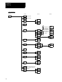
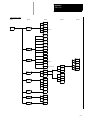
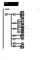
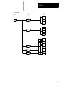
Appendix A
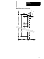
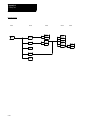
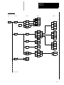
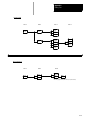
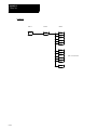
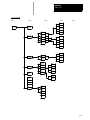
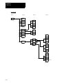
Softkey Tree
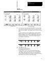
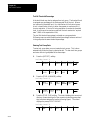
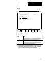
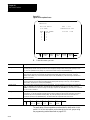
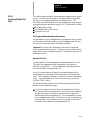
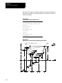
Appendix Overview . . . . . . . . . . . . . . . . . . . . . . . . . . . . . . . . . . . . . . . . . . . . . . . . . . . . . . . . . . . . . . . .
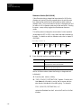
Understanding Softkeys . . . . . . . . . . . . . . . . . . . . . . . . . . . . . . . . . . . . . . . . . . . . . . . . . . . . . . . . . . . . .
Describing Level 1 Softkeys . . . . . . . . . . . . . . . . . . . . . . . . . . . . . . . . . . . . . . . . . . . . . . . . . . . . . . . . . .
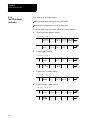
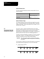
Using the Softkey Tree . . . . . . . . . . . . . . . . . . . . . . . . . . . . . . . . . . . . . . . . . . . . . . . . . . . . . . . . . . . . .
Appendix B
Error and System Messages
Overview . . . . . . . . . . . . . . . . . . . . . . . . . . . . . . . . . . . . . . . . . . . . . . . . . . . . . . . . . . . . . . . . . . . . . . .
Appendix Overview . . . . . . . . . . . . . . . . . . . . . . . . . . . . . . . . . . . . . . . . . . . . . . . . . . . . . . . . . . . . . . . .
Interpreting G--codes . . . . . . . . . . . . . . . . . . . . . . . . . . . . . . . . . . . . . . . . . . . . . . . . . . . . . . . . . . . . . . .
Appendix C
G-code Tables
Appendix Overview . . . . . . . . . . . . . . . . . . . . . . . . . . . . . . . . . . . . . . . . . . . . . . . . . . . . . . . . . . . . . . . .
29-1
29-1
29-4
29-5
29-8
30-1
30-1
30-2
30-7
30-12
30-13
30-18
30-19
30-22
30-25
30-27
30-29
30-32
30-32
30-34
30-35
30-37
30-38
30-40
A-1
A-1
A-3
A-3
B-1
C-1
C-1
D-1
xi
TableIndex
of Contents
(General)
9/Series Lathe
9/Series PAL Reference
Manual
Operation and Programming Manual
G-code Compatibility Considerations . . . . . . . . . . . . . . . . . . . . . . . . . . . . . . . . . . . . . . . . . . . . . . . . . . . .
M-code Compatibility Considerations . . . . . . . . . . . . . . . . . . . . . . . . . . . . . . . . . . . . . . . . . . . . . . . . . . .
Offset Compatibility Considerations . . . . . . . . . . . . . . . . . . . . . . . . . . . . . . . . . . . . . . . . . . . . . . . . . . . . .
Additional Feature Compatibility Considerations . . . . . . . . . . . . . . . . . . . . . . . . . . . . . . . . . . . . . . . . . . . .
9/Series G-codes Applicable to the 7300 Series CNC . . . . . . . . . . . . . . . . . . . . . . . . . . . . . . . . . . . . . . . .
7300 Series Features Not Supported . . . . . . . . . . . . . . . . . . . . . . . . . . . . . . . . . . . . . . . . . . . . . . . . . . .
xii
D-1
D-7
D-8
D-9
D-12
D-13
Chapter
1
Using This Manual
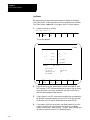
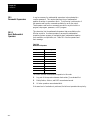
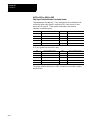
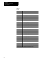
1.0
Chapter Overview
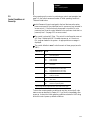
This chapter describes how to use this manual. Major topics include:
Topic
On page:
Manual organization
1-1
Reading this manual
1-3
Terms and conventions
1-4
Related publications
1-5
1.1
Audience
We intend the audience for this manual to be people who program and/or
operate an Allen-Bradley 9/Series CNC. This family includes the 9/230,
9/240, 9/260, and 9/290 CNCs. We assume that the reader has some
familiarity with the basic operation and programming of a CNC.
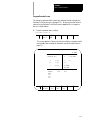
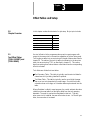
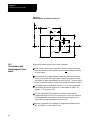
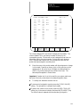
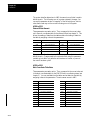
1.2
Manual Design
We divided the manual this way:
For information about:
Refer to:
how to locate control features
chapters 2
how to operate the control
chapters 3 - 9
how to program the control
chapters 10 - 29
how to use dual processing
chapter 30
softkeys
appendix A
error and operator messages in alphabetical order
appendix B
standard G-codes used to program the control
appendix C
the Allen-Bradley 7300 Series CNC tape reader
appendix D
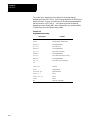
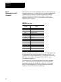
Table 1.A provides a summary of each chapter.
1-1
Chapter 1
Manual/MDI Operation Modes
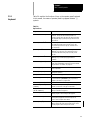
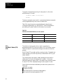
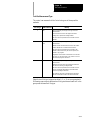
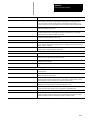
Table 1.A
Manual Organization
Chapter
1-2
Title
Summary
1
Manual Overview
Manual overview, intended audience, definition of key terms, how to proceed.
2
Basic Control Operation
A brief description of the control’s basic operation including power up, MTB panel, operator panel,
access control, and E-STOP.
3
Offset Tables and Setup
Basic setup of the offset table, other initial operating parameters.
4
Manual and MDI Operation
How to use the manual operate mode including, homing the machine, jog hand-wheel, jog
continuous, and jog increment. Also covered are the basics for MDI operation.
5
Editing Programs On Line
How to create, edit,and save a part program on line.
6
Editing Part Program Off Line
How to create, edit, and save a part programs from ODS off line.
7
Running a Program
How to select and execute a program automatically. This covers program checking as well as part
production. Also details on special running conditions.
8
Displays/ Graphics
How to access and interpret the different position displays. How to use the Quick Check and Active
Program graphics features.
9
Communications
Communications with peripheral devices. Includes sections on communication port parameters,
inputting and outputting AMP, PAL, Offsets, and programs.
10
Introduction to Programming
Tape format, structure and format of the programming language for the control.
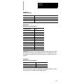
11
Coordinate System Offsets
Machine coordinate system, Preset Work coordinate systems, PAL offsets, and external offsets
12
Overtravels and Programmable
Zones (G22, G23)
Hardware and software overtravels, programmable zone 2 (G22, G23), programmable zone 3
(G22.1, G23.1), and resetting overtravels
13
Coordinate Control
Describes absolute/incremental modes, inch/metric modes, radius/diameter modes, and scaling
14
Axis Motion
G-words define how the tool is positioned to the endpoint of a move. Also sections on automatic
machine home, dwell, mirroring, and axis clamp
15
QuickPath Plus
Describes QuickPath Plus programming
16
Chamfering and Corner Radius
Describes the ,C- and ,R-words programmed for chamfering and corner radius
17
Spindles
Describes spindle speed control, spindle orientation, spindle direction, and Virtual C axis
18
Programming Feedrates
Describes acc/dec, AMP-assigned feedrates, feedrate control, short block acc/dec
19
Dual Axis Operation
Describes parking, homing, programming, offset management for a dual axis
20
Tool Control
Selecting a tool. Activating and deactivating tool length offsets. Also tool control features such as
Random Tool and Tool Life Management.
21
Tool Tip Radius Compensation
Describes the Tool Tip Radius Compensation feature (TTRC) that offsets for different tool diameters.
22
Single-- Pass Turning Cycles
23
Grooving/Cutoff Cycles
Description and use of fixed (canned) cycles for turning operations, and the G-- codes and parameters
used to define them.
24
Compound Turnign Routines
25
Thread Cutting
26
Drilling Cycles
Description and use of the fixed (canned) cycles for drilling operations and the G-- codes and
parameters used to define them.
27
Skip and Gauging Cycles
Describes the 9/Series Probing features. Includes the tool measuring gauge feature.
28
Paramacros
Describes paramacros including calling, arithmetic functions, looping, decision making
29
Program Interrupts
Describes the program interrupt feature. This feature is used to call a subprogram or paramacro
program whenever a signal corresponding to that program is sent to PAL by the operator.
Chapter 1
Manual/MDI Operation Modes
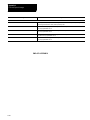
30
Using a 9/Series Dual-- Processing
System
Describes dual-- process system. Includes synchronizing multiple part programs and shared spindle
configurations.
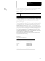
Table 1.A (continued)
Manual Organization
Appendix
Title
Summary
Appendix A
Softkey Tree
Describes softkeys and their functions for softkey levels 1 and 2. Also, the softkey tree displaying all
levels of softkeys and their location is shown.
Appendix B
Error and System Messages
An alphabetical listing of 9/Series system messages with brief descriptions.
Appendix C
G-- code Tables
Lists the G-codes used to program the control.
Appendix D
A-B 7300 Series CNC Tape
Compatibility
Detailed 7300 Series CNC tape compatibility feature.
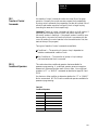
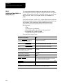
1.3
Warnings, Cautions, and
Important Information
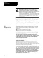
We indicate vital information in these ways:
WARNING: indicates circumstances or practices that can lead
to personal injury as well as to damage to the control, the
machine, or other equipment.
CAUTION: indicates circumstances or practices that can lead
to damage to the control or other equipment.
Important: indicates information that is necessary for successful
application of the control.
1.4
Reading this Manual
To make this manual easier to understand, we included these explanations
of terms and symbols:
All explanations, illustrations, and charts presented are based on
standard CNC functions. Operations may differ from the basic
information provided in this manual, depending on the configuration of
the machine tool controlled by the 9/Series control. For details, refer to
the manuals prepared and supplied by the system installer.
You can purchase some of the softkey functions as optional features on
your 9/Series control. This manual assumes that you purchased all of
the optional features for your machine.
1-3
Chapter 1
Manual/MDI Operation Modes
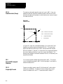
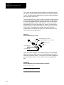
Explanations and illustrations are presented based on the movement of
the cutting tool on a fixed workpiece.
The 9/Series control lets you use any alphabetic character for expressing
a numerically controlled axis. This manual uses X and Z for the first
and second axes on the basic coordinate system, and U and W for the
axes parallel to them.
The term AMP is an abbreviation for Adjustable Machine Parameters.
These parameters are used to match the 9/Series control to a specific
machine. Your system installer usually completes the AMP setting.
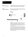
Key names designated between the [ ] symbols are found on the
operator panel.
Key names designated between the { } symbols are softkeys found
below the CRT.
Switch and button names on the standard MTB panel are designated
between the < > symbols.
The term PALt is an abbreviation for Programmable Application
Logic. This is a ladder logic program that processes signals between the
CNC and the machine. It is usually programmed by the system installer.
The manual assumes that these system characteristics are active:
Metric
Absolute
IPM
1.5
Terms and Conventions
1-4
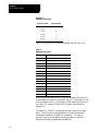
To make this manual easier to read and understand, we shortened the full
product names and features. Shortened terms include:
When you see:
It means:
AMP
Adjustable Machine Parameters
Backup
Memory storage area not requiring battery maintenance
CNC
Computer Numerical Control
CPU
Central Processing Unit (the computing part of the control)
CRT
Cathode Ray Tube (the control’s monitor screen)
The control
the 9/230, 9/240, 9/260 or 9/290 CNC
ESTOP
Emergency Stop
Flash memory
programmable, nonvolatile memory
Chapter 1
Manual/MDI Operation Modes
1.6
Related Publications
HPG
Hand Pulse Generator
I/O
Input/Output
MDI
Manual Data Input
Modal
an operating condition that remains in effect on the control until cancelled
or replaced
MTB
Machine Tool Builder
ODS
Offline Development System
PAL
Programmable Application Logic
RAM
Random Access Memory resident on the 9/240
Softkeys
the row of keys directly below the screen
Super cap
A super capacitor. Backs up data for up to 5 days on systems without
extended program storage. It recharges within 1 hour of power turn on if
completely discharged.
System installer
the company or contractor responsible for installing this control on the
machine
TTRC
Tool Tip Radius Compensation
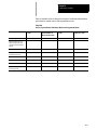
9/Series Documentation
Pub. No.
Document Name
8520-4.3
9/Series CNC PAL Reference Manual
8520-- 5.1.1
9/Series CNC Lathe Operation and Programming Manual
8520-- 5.1.3
9/Series CNC Mill Operation and Programming Manual
8520-- 5.1.4
9/Series CNC Grinder Operation and Programming Manual
8520-5.1.5
9/Series Data Highway Plus Communication Module User Manual
8520-5.1.6
9/Series MMS/Ethernet Communication Module User Manual
8520-- 5.2
9/Series CNC OCI User Manual Supplement
8520-6.2
9/Series CNC Integration and Maintenance Manual
8520-6.4
9/Series CNC AMP Reference Manual
8520-6.5
T-Line-9 Transfer Line Quick Start Guide
8520-- 6.6
9/Series CNC OCI Installation Manual
8520-- 6.7
9/Series CNC OCI API Developer’s Guide
MCD-5.1
Offline Development System User’s Manual
END OF CHAPTER
1-5
Chapter 1
Manual/MDI Operation Modes
1-6
Chapter
2
Basic Control Operation
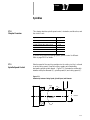
2.0
Chapter Overview
This chapter describes how to operate the Allen-Bradley 9/Series control,
including:
Topic:
On page:
MTB panel
2-10
{FRONT PANEL}
2-13
Power-up
2-21
Emergency stops
2-22
Access control
2-23
Changing modes
2-30
Display system and messages
2-34
Input cursor
2-37
{REFORM MEMORY}
2-38
Removing an axis
2-40
Time part count
2-40
We also tell you about the control conditions automatically assumed at
power up.
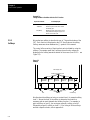
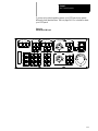
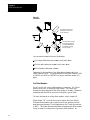
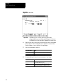
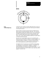
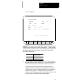
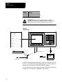
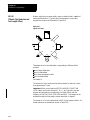
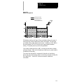
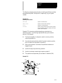
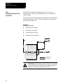
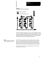
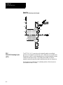
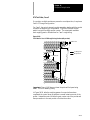
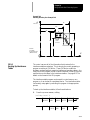
2.1
Operator Panel Operations
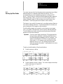
Use the operator panel to perform these operations:
display a part program
display control status and tool position
edit a part program
display and enter tool offset data
display the status of input/output signals
display and enter programmable zone boundaries
set the level of protection of part programs, tool offset data, AMP data,
etc.
Use the operator panel to perform many other operations. We describe
these operations in the remaining chapters of this manual.
Figure 2.1 shows the monochrome operator panel. Figure 2.2 shows the
color operator panel. The color operator panel has identical keys and
softkeys in a slightly different configuration.
2-1
Chapter 2
Basic Control Operation
Figure 2.1
Monochrome Operator Panel
9/SERIES
7
8
9
4
5
6
1
2
3
_
0
+
=
*
.
%
:
_
$
;
O
N
G
P
X
Y
Z
Q
I
J
K
R
A
B
C
L
#
.
EOB
]
[
(
)
CALC DEL CAN RES
F
!
E
M
SHIFT
SP
D
S
DISP PROC
?
H
o
T
TRANSMIT
19435
Figure 2.2
Color Operator Panel
9/SERIES
7
8
4
5
6
1
2
3
.
0
+
9
:
!
_
P
CALC I
G
D
F
?
E
X
$
=
N
O
_
Y
Z
Q
R
B
A
H
#
C
L
W
J
K
M
[
S
SHIFT
]
T
SP
,
&
EOB
)
(
DISP PROC
DEL CAN RES
CNTRL
LINE
TRANSMIT
19436
2-2
Chapter 2
Basic Control Operation
2.1.1
Keyboard
Table 2.A explains the functions of keys on the operator panel keyboard.
In this manual, the names of operator panel keys appear between [ ]
symbols.
Table 2.A
Key Functions
Key Name
Function
Address and Numeric Keys
Use these keys to enter alphabetic and numeric
characters. If a key has two characters printed on it,
pressing it normally enters the upper left character. Holding
down the [SHIFT] key while pressing it enters the lower
right character.
Cursor Keys Ü , Ý, Þ , ß
Use these keys to move the cursor left, right, up and down
in the data display area (lines 4-21) of the screen. We
refer to these keys as the left, right, up, and down cursor
keys respectively.
[SHIFT] and Þ or Ü
Press the right or left cursor keys while holding down the
[SHIFT] key to move the cursor right and left on any
line on which that data is being input. (normally screen
lines 2-3).
[SHIFT] and Ý or ß
Press the up or down cursor key while holding down the
[SHIFT] key to roll the display page forward or
backwards.
Calculation Key [CALC]
Pressing this key enables a calculator type function on the
control. Basic mathematical expressions may be evaluated
using this feature. For details, see page 2-4 .
Delete Key [DEL]
Pressing this key deletes the character to the left of the
cursor on input lines.
[SHIFT] and [DEL]
Pressing this key deletes all keyed-in data currently
displayed on input lines.
[CAN]
Clear the most recently generated, active error message
Transmit Key [TRANSMIT]
The data entered and displayed on the input lines is sent to
the control when the [TRANSMIT] key is pressed, for
example a password or a program block.
Block Reset [RESET]
This performs a block reset. See page 2-4 .
Control Reset [RESET] +
[SHIFT]
Pressing the reset key while holding down the shift key
performs a control reset. See page 2-4 for details.
Display Select
[DISP SELECT]
Use this key to display the different axis position display
softkeys as described on page 8-1.
End of Block [E.O.B.]
Use this key to enter an End of Block character when
editing a program or when writing an MDI program.
[PROC SELECT]
This key is used for dual process lathe systems only.
Pressing this key toggles the control from process to
process. Refer to chapter 30 for details.
[SHIFT] and [Þ ]
Press the [SHIFT] key while holding down the [Þ ]
softkey to jump to the online search monitor screen. Press
these keys again to return to the previous screen.
2-3
Chapter 2
Basic Control Operation
Reset Operations
If you are using a dual-processing system, refer to page 30-6 for details
about reset operations.
Block Reset
Use the block reset feature to force the control to skip the block execution.
To use the block reset function, program execution must be stopped. If
program execution stops before the control has completely finished the
block execution, a block reset aborts any portion of that block that has not
been executed. If program execution stops after the complete block
execution (as in the case of single block execution or a M00 etc.), the
control aborts the execution of the entire following block.
Press [RESET] key on the operator panel to perform a block reset.
Control Reset
You can return the control to the default parameters, clear any
programming errors, and cancel any MDI commands by executing a
control reset. After you execute a control reset, any active program resets
to the first block; any programmed offsets or rotations of the coordinate
systems reset to default, and any MDI command is discarded. All of the
operating parameters return to the standard AMP-assigned values,
including any AMP-assigned G-codes active at power-up (except
Inch/Metric which remains in its last programmed state at control reset).
Press the [RESET] key on the operator panel while holding down the
key to execute a control reset.
[SHIFT]
2.1.2
Calculator Function
The 9/Series control is equipped to evaluate simple mathematical
expressions during the course of operation or programming.
To use the calculator function, line 2 of the screen must be blank. There
can be no prompt on the input line of the screen when you attempt to do
calculations. This completely disables any calculation operation when in
MDI mode. If you attempt to enter the calculator function while another
prompt is active, the control generates the error message “CANNOT
CALCULATE - PROMPT PRESENT.”
Use the calculator function as follows:
2-4
1.
Press the [CALC] key on the operator panel. The “CALC:” prompt
appears on the input line of the screen (line 2).
2.
Enter a mathematical equation on the input line by pressing the
desired keys on the operator panel.
3.
Press the [TRANSMIT] key to evaluate the expression. The answer to
the expression is displayed on the input line.
Chapter 2
Basic Control Operation
Expressions entered on the input line cannot exceed a total of 25
characters. Only numeric or special mathematical operation characters as
described below can be entered next to the “CALC:” prompt. Any
character that is not numeric or an operation character you enter on the
input line generates the error message “INVALID CHARACTER.”
The largest number you can enter for a calculate function is 214748367.
You cannot enter a number larger than 10 digits. If control displays a
number that is too large (longer than 10 digits), the control displays the
error message “NUMBER IS OUT OF RANGE”. If the number entered or
calculated is greater than 10 digits, control displays the error message
“MATH OVERFLOW.”
Any fractional numbers cannot exceed .999999 (6 decimal places). If you
exceed this number of decimal places, the control automatically rounds off.
If this seventh digit is less than 5, the control rounds down. If this seventh
digit is 5 or greater, the control rounds up.
Any data entered on the input lines can be edited as described on page
2-37.
To disable the calculator function, press the [CALC] key again. The
“CALC:” prompt is removed from the input line.
Use the characters in Table 2.B to indicate mathematical operations.
Table 2.B
Mathematical Operators
*
Multiplication
/
Division
+
Addition
-
Subtraction
[]
Brackets
#
Get Paramacro Value
The control executes mathematical operations in this order:
1.
Any part of the expression that is between the brackets [ ] is
evaluated first. The values of paramacro variables are also
substituted for the #xxxx as the first operation performed.
2.
Multiplication and division are evaluated second.
3.
Addition and subtraction are evaluated last.
If the same level of evaluation is performed the left most operation takes
priority.
2-5
Chapter 2
Basic Control Operation
Example 2.1
Mathematic Expressions
Expression Entered
Result Displayed
12/4*3
9
12/[4*3]
1
12+2/2
13
[12+2]/2
7
12-4+3
11
12-[4+3]
5
Table 2.C lists the function commands available with the [CALC] key.
Table 2.C
Mathematical Functions
Function
Meaning
SIN
Sine (degrees)
COS
Cosine (degrees)
TAN
Tangent (degrees)
ATAN
Arc Tangent (degrees)
ASIN
Arc Sine (degrees)
ACOS
Arc Cosine (degrees)
SQRT
Square Root
ABS
Absolute Value
BIN
Conversion from Decimal to Coded Decimal
BCD
Conversion from Coded Decimal to Decimal
ROUND
Rounding Off (nearest whole number)
FIX
Truncation Down
FUP
Truncation Up
LN
Logarithms (natural log)
EXP
Exponent
When you program these functions, place the value that the function is to
be performed on in brackets, for example, SIN [10]. The exception to this
is the arc tangent function. The format for ATAN requires the division of
two values. For example, ATAN [10]/[2] is used to calculate the arc
tangent of 5.
The functions in Table 2.C are executed from left to right in a program
block. These functions are executed before the control executes any
mathematical operators like addition or subtraction. This order of
execution can only be changed by enclosing operations in brackets [ ].
Operations enclosed in brackets are executed first.
2-6
Chapter 2
Basic Control Operation
Example 2.2
Format for [CALC] Functions
SIN[2]
This evaluates the sine of 2 degrees.
SQRT[14+2]
This evaluates the square root of 16.
SIN[SQRT[14+2]]
This evaluates the sine of the square root of 16.
Example 2.3
Mathematical Function Examples
Expression Entered
Result
SIN[90]
1.0
SQRT[16]
4.0
ABS[-4]
4.0
BIN[855]
357.0
BCD[357]
855.0
ROUND[12.5]
13.0
ROUND[12.4]
12.0
FIX[12.7]
12.0
FUP[12.2]
13.0
FUP[12.0]
12.0
LN[9]
2.197225
EXP[2]
7.389056
Important: Precaution must be taken when performing calculations within
the brackets [ ]. The operations within the bracket are performed first, and
then the function is performed on this resultant. For example:
ROUND[2.8+2.6];
The result of this is 5.0
The values in the brackets are added together first and then rounded, not
rounded and then added together.
Paramacro Variables in CALC Operations
Any paramacro variable can be accessed through the CALC function.
Include a # sign followed by the paramacro variable number. When the
calculation is performed the value of that paramacro variable is substituted
into the equation. You can not change the value of paramacro variables
with the CALC function. Local parameters are only available for the
currently active nesting level of the control (main program, or one of four
nested macro programs). You can not perform calculations that contain
any paramacro variables if the control is currently executing a program
block. The control must be in either cycle stop state, or E-Stop.
2-7
Chapter 2
Basic Control Operation
Example 2.4
Calling Paramacro Variables with the CALC Function
Expression Entered
2.1.3
Softkeys
Result Displayed
#100
Display current value of variable #100
12/#100*3
Divide 12 by the current value of #100
and multiply by 3
SIN[#31*3]
Multiply the value of #31 (for the current
local parameter nesting level) by 3 and
take the sine of that result
We use the term softkey to describe the row of 7 keys at the bottom of the
CRT. Each function is displayed on the CRT directly above the softkey.
Softkey names are shown between the { } symbols in this manual.
The control offers a variety of functions that can be initiated by using the
softkeys. The operator panel has 5 softkeys whose function names are
displayed in the softkey area at the bottom of the screen (lines 23-25 — see
Figure 2.3).
Figure 2.3
Softkeys
Data display area
Softkey name display area
PRGRAM
MANAGE
Exit
OFFSET
MACRO
PARAM
Softkeys
PRGRAM
CHECK
SYSTEM
SUPORT
Continue key
We often describe softkeys as being on a certain level, for example softkey
level 3. We use the level of the softkey to determine the location or
necessary path to reach that particular softkey function. For example, to
get to a softkey on level 3, you must press a specific softkey on level 1,
followed by a specific softkey on level 2. For a listing of all the softkeys
and their respective levels, refer to appendix A.
2-8
Chapter 2
Basic Control Operation
Softkey level 1 is the initial softkey level the control displays at power-up.
Softkey level 1 always remains the same and all other levels are referenced
from softkey level 1.
The softkeys on opposite ends of the softkey row have a specific use that
remains standard throughout the different softkey levels.
On the:
Is the:
left
exit softkey displayed with the up arrow {Ý}
right
continue softkey displayed with the right arrow {Þ }
Use the exit softkey {Ý} on the far left to regress softkey levels. For
example, if you are currently on softkey level 3 and you press the exit
softkey, the softkeys change to the softkeys previously displayed on
softkey level 2. When you press the exit softkey while holding down
the shift key, the softkey display is returned to softkey level 1 regardless
of the current softkey level.
When more than 5 softkey functions are available on the same level, the
control activates the continue {Þ } softkey at the far right of the softkey
area. When you press the continue softkey, the softkey functions
change to the next set of softkeys on that level.
Important: The continue softkey is not active when the number of softkey
functions on that level does not exceed 5.
For example:
(softkey level 1)
PRGRAM OFFSET MACRO
MANAGE
PARAM
PRGRAM SYSTEM
CHECK SUPORT
When softkey level 1 is reached, the above set of softkeys is displayed.
Pressing the continue softkey {Þ } displays the remaining softkey
functions on softkey level 1.
(softkey level 1)
FRONT
PANEL
ERROR PASSMESAGE WORD
SWITCH
LANG
The exit softkey is not displayed since the softkeys are already on softkey
level 1.
The softkey functions for level 1 and level 2 are explained in appendix A.
Softkey functions for level 3, or higher, are explained in the sections that
apply to their specific operations.
2-9
Chapter 2
Basic Control Operation
To use a softkey function, press the plain, unmarked button directly below
the description of the softkey function.
Important: Some of the softkey functions are purchased as optional
features. This manual assumes that all available optional features have
been purchased for the machine. If an option is not purchased, the softkey
is blank.
2.1.4
CRT
The control can be purchased with a 9-inch monochrome monitor or a
12-inch color monitor.. Both have identical displays and graphics
capabilities.
Certain lines of the screen are dedicated to displaying specific information:
2.2
The MTB Panel
Lines:
Display information:
line 1
machine/
system message area
If an error occurs or a message is generated for any reason during
machine operation or program execution, the control displays the
corresponding machine/system message in this area. Only the
highest priority, most current message is displayed here.
lines 2-3
input lines
When you enter data using the keyboard, the control displays the
characters corresponding to the keys pressed until you press the
[TRANSMIT] key. Some screens can only have line 2 as an input
line.
lines 4-20
data display area
The control displays axis position data, listing of the part program, tool
offset data, G-, M-, H-, T-, F-, S-, and D-codes, graphics, and other
data, as determined by the selected display. See chapter 8.
lines 21-22
PAL message area
The control displays any messages generated by the control’s PAL
program in this area
lines 23-25
softkey display area
The control displays the currently available softkey functions in this
area.
Figure 2.4 shows the push-button MTB panel. Table 2.D explains the
functions of the buttons on the MTB panel. Optional or custom MTB
panels may be used. Refer to the documentation prepared by your system
installer for details.
We show switches and button names that are found on the rotary and
push--button MTB panel between the < > symbols throughout this manual.
The push-button MTB panel uses defaults when you turn on power to the
control. Table 2.D contains these defaults.
Most of the buttons on the MTB panel are configured by your system
installer’s PAL program. We assume that PAL has been written as
intended for normal operation. If a switch does not work the way it is
described in this manual, refer to documentation prepared by your system
installer.
2-10
Chapter 2
Basic Control Operation
If you are using a dual-operating system, your MTB panel may operate
differently than described here. Refer to page 30-11 for information about
your MTB panel.
Figure 2.4
Push-Button MTB Panel
MODE SELECT
AUTO
MDI
JOG SELECT
MAN
INCR
CONT
HAND
HOME
SPINDLE SPEED
OVERRIDE
SPEED/MULTIPLY
LOW
X1
MEDL
X10
MEDH
X1000
AXIS
SPINDLE
MED
X100
HIGH
X10000
CCW
50
FUNCTION
CYCLE
START
+X
+4
--X
F1
F2
SINGLE
BLOCK
+Y
TRVRS
--Y
F3
F4
CYCLE
STOP
+Z
--4
--Z
F5
F6
FEEDRATE
OVERRIDE
50
0
ESTOP
RESET
OFF
120
ON
CW
OFF
RAPID FEEDRATE
OVERRIDE
100
%
150
F1
25
50
100
19930
2-11
Chapter 2
Basic Control Operation
Table 2.D
Functions of the Buttons on the Push-Button MTB Panel
Switch or Button Name
MODE SELECT
How It Works
= Default for Push-Button MTB Panel
Selects the operation mode
AUTO - - automatic mode
MANUAL - - manual mode
MDI - - manual data input mode
JOG SELECT
Selects the jog method to be active in manual mode
HANDWHEEL - - HPG (hand pulse generator) jog
INCREMENTAL - - incremental jog
CONTINUOUS - - continuous jog
HOME - - machine home
SPEED/MULTIPLY
Selects an axis feedrate or axis feed amount multiplication ratio used in the manual mode. Each
selection modifies the active feedrate by a value set in AMP. Modification also depends on the setting
of <JOG SELECT> as described below:
·HANDWHEEL
When in handwheel jog mode, SPEED/MULTIPLY alters the handwheel resolution by a factor
determined in AMP. Your system installer sets the value for:
- LOW X1
- MEDL X10
- MEDL X100
You cannot use the values listed below for handwheel jog:
- MEDH X1000
- HIGH X10000
·INCREMENTAL
When in incremental jog mode, SPEED/MULTIPLY alters the incremental jog distance by a factor set
in AMP by your system installer. Your system installer sets a value for the selections. The
incremental jog speed is fixed to medium but can still be controlled by
<FEEDRATE OVERRIDE>.
·CONTINUOUS
When in continuous jog mode, SPEED/MULTIPLY acts as a feedrate selection switch which has
values set in AMP by your system installer. Your system installer sets a value for all 5 selections
independently for each axis. <FEEDRATE OVERRIDE> can be used for speed adjustments.
Important: The values for the different <SPEED/MULTIPLY> selections are configured by
your system installer.
2-12
SPINDLE SPEED OVERRIDE
Selects the override for programmed spindle speeds in 5% increments within a range of 50% to 120%.
SPINDLE or
SPINDLE DIRECTION
Selects spindle rotation, clockwise (CW), spindle stop (OFF), counterclockwise (CCW). Can be
overridden by any programmed spindle direction command.
FEEDRATE OVERRIDE
Selects a feedrate override percentage for the feedrate programmed with an F word in any of the
feedrates modes (G93/G94/G95) and the reciprocation feedrate programmed with an E word.
<FEEDRATE OVERRIDE> has a range of 0% to 150% of the programmed feedrate and alters the
programmed feedrate in 10% increments. When set to 0%, the control is effectively in feedhold.
RAPID FEEDRATE OVERRIDE
Selects the override for rapid feedrates. Select from F1, 25%, 50%, and 100% where F1 is a rapid
feedrate override setting established in AMP by the system installer.
EMERGENCY STOP
This button stops machine operation and disables the spindle and axis drives when pressed.
E-STOP RESET
This button resets an emergency stop condition when pressed. Before pressing this button the
condition that caused the E-Stop should be resolved.
CYCLE START
The control begins or resumes part program execution, MDI program execution, or program check
when this button is pressed.
Chapter 2
Basic Control Operation
Table 2.D (continued)
Functions of the Buttons on the Push-Button MTB Panel
Switch or Button Name
How It Works
= Default for Push-Button MTB Panel
CYCLE STOP
The control stops part program execution, MDI execution, or program check when this button is
pressed. If pressed during the execution of a program block a cycle suspend state occurs.
SINGLE BLOCK
The control executes or checks one block of a part program or MDI entry each time the
<CYCLE START> button is pressed when single block is active.
AXIS/DIRECTION
These buttons are used for manual operations. They select an axis and direction when
<JOG SELECT> is set for continuous, incremental, or home. If <JOG SELECT> is set for
handwheel, these buttons select an axis only. Direction is then determined by handwheel rotation.
TRVRS
Hold this button down while executing a continuous jog move to override the active feedrate and jog an
axis in rapid traverse.
F1 - F4
The functions for these buttons are assigned by the system installer. Refer to the documentation
prepared by the system installer for details.
JOG RETRACT
Use jog retract to jog a cutting tool away from the workpiece during automatic or MDI program
execution. The control can retrace the jog moves and return the cutting tool automatically to the
workpiece by pressing <CYCLE START>. Refer to page 7-28 for more on this.
BLOCK RETRACE
To retrace the tool path in a part program already executed (up to 15 blocks), press this button.
ON
Turns on power to the control.
OFF
Turns off power to the control.
Important: Many of the override switch settings may be disabled by
programming the correct M-code or setting a particular paramacro
parameter. Refer to their respective sections for details on these features.
2.3
Software MTB Panel
{FRONT PANEL}
The 9/Series control offers a software MTB panel that performs many of
the functions of an MTB panel. This feature uses softkeys instead of the
normal switches and buttons of a panel. If the control uses a push-button
MTB panel (described on page 2-10), or some other custom panel, the
requests for operations from the panel takes priority. This means that
requests of the software MTB panel are ignored if another request is sent
from a push-button MTB panel or a custom MTB panel.
The software MTB panel’s operation depends on PAL, especially if the
control uses a push-button MTB panel or a custom MTB panel. Refer to
documentation prepared by your system installer for details on using the
software MTB panel. Your system installer uses PAL to disable the
{FRONT PANEL} softkey.
Important: By using the PAL flags $SWF1 and $SWF2, you can enable
and disable features available on the software front panel. Refer to your
PAL reference manual for additional information.
2-13
Chapter 2
Basic Control Operation
The software MTB panel can control these features:
Feature
2-14
Description
Mode Select
Select either Automatic, MDI, or Manual modes as the current operating mode of the control.
Rapid Traverse
This feature replaces the feedrate when executing a continuous jog move with the rapid feedrate.
Feedrate Override
Selects a feedrate override percentage for feedrates programmed with an F-word, in 10% increments within a
range of 0% to 150%. When set to 0%, the control is effectively in feedhold.
Rapid Feedrate Override
Selects the override for rapid feedrates. Select from F1, 25%, 50%, and 100%, where F1 is a rapid feedrate
override setting established in AMP by the system installer.
Spindle Direction
Selects spindle rotation, clockwise (CW), spindle stop (OFF), or counterclockwise (CCW). Is overridden by
any programmed spindle direction command.
Spindle Speed Override
Selects the override for programmed spindle speeds in 5% increments within a range of 50% to 120%.
Dry Run Mode
Places the control in Dry Run Mode. This replaces feedrates with the Dry Run feedrates. See page 7-21.
Block Delete
Allows the activation of the block delete feature “/ or /1”(see page 7-1 ). Block delete 2 - 9 are not available
with the {FRONT PANEL}.
M-Function Lock
Allows select M-, S-, T-, and B-codes to be ignored. See page 7-2.
Optional Stop
This enables or disables the M01 optional stop code. When this feature is “ON,”an M01 in a part program
stops automatic execution. When this feature is “OFF,”an M01 in a part program is ignored. See page 10-30
for details on M01.
Single Block
The control executes or checks one block of a part program or MDI entry each time the <CYCLE START>
button is pressed when this feature is on.
Mirror Image
Mirrors the axis commands in the part program around the selected axis. See page 14-19.
Axis Inhibit
Prevents axis commands from being executed. The control simulates axis motion on inhibited axes by using
Acc/Dec and feedrates; however, no actual axis motion for the inhibited axes is generated. See page 7-20.
Jog the Axes
Allows manual motions to be performed in any one of the jogging modes. See section 4.1. Multi-axis jogs
may not be performed by using the Software MTB feature.
Set Zero
Change the tool’s current position in the work coordinate system to 0 for the selected axis. This is done by
shifting the work coordinate system. See page 11-18.
Block Retrace
This allows up to 15 part program blocks to be retraced during program execution and allow the tool to
automatically re-execute these blocks. See page 7-31.
Jog Retract
Allow the tool to be manually jogged away from the part and then automatically return the tool to the part by
retracing the jogged moves. Up to 15 jog moves can be remembered. See page 7-28.
Cycle Start
The control begins or resumes part program execution, MDI program execution, or program check when you
press this button.
Cycle Stop
The control stops part program execution, or program check when you press this button. If pressed during the
execution of a program block, a cycle suspend state occurs.
Chapter 2
Basic Control Operation
Software MTB Panel Screen
To use the software MTB panel feature, follow these steps:
1.
From the main menu screen, press the {FRONT PANEL} softkey.
(softkey level 1)
PRGRAM OFFSET MACRO
MANAGE
PARAM
PRGRAM SYSTEM
CHECK SUPORT
FRONT
PANEL
SWITCH
LANG
ERROR PASSMESAGE WORD
The Software MTB Panel screen displays the current status of the
alterable features.
SOFTWARE FRONT PANEL
MODE SELECT:
MDI
RAPID TRAVERSE:
OFF
FEEDRATE OVR:
0%
RAPID FEEDRATE OVR:
100%
SPINDLE DIRECTION:
CW
SPINDLE SPEED OVR:
50%
DRY RUN MODE:
OFF
BLOCK DELETE:
OFF
M-FUNC LOCK:
OFF
OPTIONAL STOP:
OFF
SINGLE BLOCK:
OFF
MIRROR IMAGE:
AXIS INHIBIT:
USE CURSOR FOR SELECTION
JOG
AXIS
PRGRAM
EXEC
2.
Press the up or down cursor keys to select the function you want to
change. The selected function appears in reverse video.
3.
Alter the value of the function by pressing the left or right cursor keys
(except for the Mirror Image and Axis Inhibit features). When you
select the Mirror Image or Axis Inhibit features, the softkey names
change to the axis names. Press the softkey that corresponds to the
axis (or axes) that you want to assign to these features.
2-15
Chapter 2
Basic Control Operation
Jog Screen
We assumes that you have performed the steps to display the Software
Front Panel screen. Make sure that the function selected on the Software
Front Panel screen is not the Mirror Image or the Axis Inhibit features.
1.
Press the {JOG AXIS} softkey.
(softkey level 2)
JOG
AXIS
PRGRAM
EXEC
This screen appears:
E-STOP
PROGRAM [mm]
F
0.000 MMPM
0.0
Z
0.000
S
R X
0.000
T 0
C
359.99
FILENAME
SUB NAME
MEMORY
MAN
AXIS SELECT:
JOG SELECT:
SPEED/MULTIPLY
HPG NUMBER
SET
ZERO
2-16
STOP
X
CONTINUOUS
LOW
0
JOG
JOG
AXIS + AXIS -
2.
Select the axis, jog type, speed multiply value (see chapter 4), and
HPG number (if HPG has been selected as the type of jog) by using
the up and down cursor keys, and the left and right cursor keys to
alter the value assigned to that function.
3.
If the jog type is not HPG, then press the softkey that corresponds to
the direction on the selected axis to jog (if HPG is the jog type then
the direction of HPG rotation determines the direction to jog).
4.
If you want to shift the current work coordinate system to force the
current tool position to be the zero point of the work coordinate
system, press the {SET ZERO} softkey. The {SET ZERO} softkey does
not function when the control is in handwheel mode.
Chapter 2
Basic Control Operation
Program Execute Screen
The following assumes that the steps have been performed to display the
Software Front Panel screen (see page 2-15). Make sure that the function
selected on the Software Front Panel screen is not the Mirror Image nor
the Axis Inhibit feature.
1.
Press the {PRGRAM EXEC} softkey.
(softkey level 2)
JOG
AXIS
PRGRAM
EXEC
This screen appears. Before you press this softkey, a program should
have already been selected for automatic execution as described on
page 7-6.
E-STOP
PROGRAM[ MM
]
F
0.000 MMPM
Z
0.000
S
0.0
R X
0.000
T 0
C
359.99
FILENAME
SUB NAME
MEMORY
MAN
STOP
M100;
G90;
Z10;
G70;
BLOCK JOG
CYCLE
RETRCE RETRCT START
CYCLE
STOP
2-17
Chapter 2
Basic Control Operation
2.
Select one of these softkey options:
block retrace
jog retract
cycle start
cycle stop
3.
To Perform a:
Press:
Cycle Start
the softkey that corresponds to the desired feature. Details on these
features are described in chapter 7.
Cycle Stop
the softkey that corresponds to the desired feature. Details on these
features are described in chapter 7.
Block Retrace
the {BLOCK RETRCE} softkey. The control automatically
retraces the previously executed block each time you press. The tool
returns to the start point of Block Retrace when you press the
{CYCLE START} softkey. Details on Block Retrace can be found
in chapter 7.
Jog Retract
the {JOG RETRCT} softkey. This calls up the jog retract screen.
Select: the axis, the type of jog, the speed multiply value (see
chapter 4), or the HPG number (if HPG has been selected as the
type of jog). Use the up and down cursor keys to select the function,
and the left and right cursor keys to alter the value assigned to that
function.
Press the {JOG AXES +} or {JOG AXES -} softkeys to select the
direction to jog the axis. Press the exit {Ý} softkey when you
complete the jog retract. The cutting tool automatically retraces the
jog moves you made when you pressed the {CYCLE START}. See
chapter 7.
(softkey level 4)
SET
ZERO
2-18
JOG
JOG
AXES + AXES-
Chapter 2
Basic Control Operation
Figure 2.5
Jog Retract Software MTB Panel Screen
E-STOP
PROGRAM[ MM
]
F
Z
00000.000
S
R X
00000.000
T
C
359.99
00000.000 MMPM
0
12
FILENAME
SUB NAME
MEMORY
JOG
AXES+
MAN
STOP
JOG
AXES-
2.4
Power Procedures
The basic procedure for turning power on and off is described in this
section. Refer to the documentation prepared by your system installer for
more specific procedures.
2.4.1
Turning Power On
Follow this procedure to turn on power to the control:
1.
Visually check to make sure that the control and the machine are in
normal operating conditions.
2.
Press the power <ON> button.
Important: Do not touch any other buttons after you press the power <ON>
button until characters appear and remain on the screen.
3.
If characters are not displayed on the screen within 15 seconds, press
the power <OFF> button immediately.
Important: If the screen does not display characters after you press the
power <ON> button within a reasonable warm up period (about 15 seconds),
immediately press the power <OFF> button and contact service personnel.
2-19
Chapter 2
Basic Control Operation
After power has been turned on, the control displays the power turn-on
screen. To activate the main menu, press the [TRANSMIT] key.
You see the main menu screen:
E-STOP
PROGRAM[ MM
]
F
Z
00000.000
S
R X
00000.000
T
C
359.99
00000.000 MMPM
12345
FILENAME
SUB NAME 9999
MEMORY 30000 MDI
STOP
(PAL messages)
PRGRAM OFFSET MACRO
MANAGE
PARAM
PRGRAM SYSTEM
CHECK SUPORT
The softkeys available on the main menu screen are referred to as “level 1”
softkey functions. Some of the softkey functions are purchased as optional
and may not appear exactly as shown.
2.4.2
Turning Power OFF
Follow this procedure to turn off power to the control:
CAUTION: To prevent damage to the machine, never turn off
power while a part program is being executed. Before turning
off power, make sure that the control is in CYCLE STOP.
2-20
1.
Before you turn the power off, make sure that the control is in
CYCLE STOP.
2.
Press the <EMERGENCY STOP> button.
3.
Make sure that power is turned off to all peripheral devices (tape
reader, tape punch, etc.) that are connected to the control.
4.
Press the power <OFF> button.
Chapter 2
Basic Control Operation
2.5
Control Conditions at
Power-Up
After powering up the control or performing a control reset operation (see
page 2-4), the control assumes a number of initial operating conditions.
These are listed below:
Initial Password Access is assigned to the level that was active when
power was turned off (provided that level is a power-up level selected in
access control). If the active level when power is turned off is not a
power-up level, then the control defaults to the next lower level that is a
power-up level. See page 2-23 on access control.
The control is placed in E-Stop. The control is not allowed to come out
of E-Stop if the default AMP is loaded at power-up, or if there is no
PAL program loaded in the system. An appropriate error message is
displayed.
The control defaults to one G-code from each of these groups (as set in
AMP):
Modal Group:
G-code
1
G00
G01
Rapid traverse
Linear interpolation
2
G17
G18
G19
Plane Selected
Plane Selected
Plane Selected
3
G90
G91
Absolute
Incremental
4
G22
G22.1
G23
G23.1
Programmable Zone 2 and 3 (On)
Programmable Zone 2 (Off) 3 (On)
Programmable Zone 2 and 3 (Off)
Programmable Zone 2 (On) 3 (Off)
5
G94
G95
Feed per minute
Feed per revolution
6*
G70
G71
Inch mode
Metric mode
18
G07
G08
Radius Programming Mode
Diameter Programming Mode
* This G code group is only established at power up. A control reset
will not change the last programmed state of this modal G code group.
To show the current operating conditions at any time, access the G-code
status screen as described in chapter 10. If you do this immediately after
power-up, it shows the initial operating conditions selected in AMP along
with other control power-up default conditions.
2-21
Chapter 2
Basic Control Operation
2.6
Emergency Stop Operations
Press the red <EMERGENCY STOP> button on the MTB panel (or any other
E-stop switches installed on the machine) to stop operations regardless of
the condition of the control and the machine.
WARNING: To avoid damage to equipment or hazard to
personnel, the system installer should connect the
<EMERGENCY STOP> button, so that pressing the button opens the
circuit connected to the E-STOP STATUS terminal on the
control. This should disable the axis drives and the spindle
drive circuits, which should both be connected to this terminal.
Refer to the integration manual or the documentation prepared
by your system installer for details.
If equipped with a rotary or push-button MTB panel, the following occurs
automatically after you press the <EMERGENCY STOP> button:
The control displays “E-STOP” in the message area. This indicates that
the control is in the emergency stop state.
The red light in the <CYCLE STOP> button lights up to indicate that the
control is in the feedhold state.
Power to all axis drive motors is turned off.
Important: If you press the <EMERGENCY STOP> button while a part
program is running, program execution can resume at the point of
interruption. Refer to the mid-program start feature described in chapter 7.
2.6.1
Emergency Stop Reset
Before resetting the emergency stop state, first locate and eliminate the
cause of the emergency stop.
If the <EMERGENCY STOP> button is locked in the pressed position, it must
be released before the emergency stop state can be reset. The locked
button can be released in different ways depending on its type. With the
MTB panel, turn the button clockwise until it pops out.
To reset the emergency stop state, press the <E-STOP RESET> button. Once
you push the E--Stop Reset button to clear the E--Stop state, the message,
“RESETTING E--STOP” displays to alert you that the control is attempting
to come out of E--Stop. After the cause of the E--Stop is resolved, the
control clears the “E--STOP” message. If the error condition is not cleared,
the “RESETTING E--STOP” message clears, but the “E--STOP” message
continues to flash as the control remains in E--Stop state.
2-22
Chapter 2
Basic Control Operation
If the E-Stop occurred during program execution, the control may reset the
program when E-Stop reset is performed provided AMP is configured to
do so. Assuming that a control reset is performed, program execution
begins from the first block of the program when <CYCLE START> is
pressed. If the current axis position prohibits this, the operator can
manually jog the axes clear, or consider executing a Mid-Program Start.
See page 7-12. If no control reset is performed, the remainder of the
program block being executed when E-Stop took place is aborted, and a
<CYCLE START> begins program execution at the next block.
Important: If the cause of the E-Stop is not eliminated, the circuit
connected to the E-STOP STATUS terminals remains open, and the
emergency stop state is not reset even when the <E-STOP RESET> button is
pressed.
2.7
Access Control
Access control lets the system installer assign different functions of the
control to different users by means of a password. See section 2.7.2 for a
list of the functions that may be protected on the 9/Series control.
Each protectable function is assigned an access level that is made active
when the operator enters the password. When an access level is made
active, all functions that are assigned to that access level become available.
Access levels range between 1 and 8 where 1 is the highest level and 8 is
the lowest. A different password is assigned to each of the different access
levels. Eight passwords can be assigned.
Access control only applies to the front panel and softkey inputs. It cannot
control inputs from outside the system. For instance, if you control access
to the delete function, the user can’t delete a file, but a file can be deleted
by Mini-DNC software and by Data Highway with the 9/Series Data
Highway Plus Communication Module.
Important: If you do not want to use password protection, simply select
all functions as accessible for access level 8. Since access level 8 is
automatically available at power up, no password is necessary to access
any of the functions of the control. Password protection can also be
disabled by assigning a level at the power-up level by using the
“POWER UP LEVEL” parameter as described in section 2.7.2.
2-23
Chapter 2
Basic Control Operation
2.7.1
Assigning Access Levels
and Passwords
This section describes setting or changing the functions assigned to a
particular access level, and changing the password used to activate that
access level.
Important: Functions or passwords can be assigned to another access
level only if:
If you have a higher access level than the access level you are
attempting to change, this means that if your password is assigned to
access level 6, you can only change the functions or passwords for
access levels 7 and 8. Functions, or a password, cannot be assigned to
access level 6 with a level 6 password.
Functions that are not available to the current user cannot be assigned to
other levels. If a user with access level 6 is changing a lower access
level functions, access level 6 must have access to any functions that are
changed. For example, if you are an access level 6 user, you do not
have access to {SYSTEM SUPORT}, you cannot assign or remove
{SYSTEM SUPORT} to access level 7.
The current user must have access to the {ACCESS CONTROL} function.
To change the functions or password of a lower user number, follow these
steps:
1.
Press the {PASSWORD} softkey.
(softkey level 1)
PRGRAM OFFSET MACRO
MANAGE
PARAM
FRONT
PANEL
2-24
ERROR PASSMESAGE WORD
PRGRAM SYSTEM
CHECK SUPORT
SWITCH
LANG
Chapter 2
Basic Control Operation
2.
Press the {ACCESS CONTRL} softkey. If the {ACCESS CONTRL}
softkey does not appear on the screen, the currently active access
level is not allowed to use the {ACCESS CONTRL} function. Enter a
password that has access to {ACCESS CONTRL}.
(softkey level 2)
ACCESS
CONTRL
This screen appears.
PASSWORD NAME -- (current password)
1
2
3
4
5
6
7
8
9
10
11
12
13
14
15
16
17
ACTIVE PROGRAM
PROGRAM MANAGE
EDIT PROGRAM
COPY PROGRAM
RENAME PROGRAM
DELETE PROGRAM
DELETE ALL PROGRAM
OFFSETS
TOOL WEAR
TOOL GEOMETRY
ACTIVE OFFSET
BACKUP OFFSET
QUICK CHECK
SYSTEM SUPPORT
PRGRAM PARAMETER
AMP
PARAMACRO PROG
UPDATE 01
& EXIT
02
18
19
20
21
22
23
24
25
26
27
28
29
30
31
32
33
34
ACCESS CONTROL
SWITCH LANGUAGE
POWER UP LEVEL
TIME PARTS
SI/OEM MESSAGE
SCALING
CHANGE DIRECTORY
AUX COMM
SEARCH MONITOR
03
04
NOTE: Some of these protected features are not available on 9/240 controls.
The softkey names change to display the 8 access levels along with
their corresponding passwords (provided that a password has been
assigned to that access level). Only the password names of access
levels that are lower than the currently active access level are shown.
2-25
Chapter 2
Basic Control Operation
3.
Press the softkey that corresponds to the access level that you want to
change. The pressed softkey appears in reverse video, and the
password name assigned to that access level is moved to the
“PASSWORD NAME.”
Important: If you attempt to change the functions available to an access
level that is equal to or higher than your the current access level, the error
message “ACCESS TO THIS LEVEL IS NOT ALLOWED.” You cannot
change the features that are assigned to your current access level or any
level that is higher than your own.
(softkey level 3)
UPDATE 01
02
03
04
& EXIT (NAME) (NAME) (NAME) (NAME)
4.
If you want to enter or change the password for the selected level,
edit the password next to the “PASSWORD NAME” prompt by using
the input cursor as described on page 2-37. If you also want to
change the functions for this password, move on to step 5. To save
the change made to the password and leave the access control screen
press the {UPDATE & EXIT} softkey.
Functions that are currently available to the selected level are shown
in reverse video on the access level screen.
5.
Use the up, down, right, and left cursor keys to select the functions to
change for that access level. The selected function is shown with a
flashing > to the left of the function.
6.
Pressing the [TRANSMIT] key toggles the function between accessible
and inaccessible for that access level.
Important: If you attempt to activate or deactivate a function that is not
accessible to the current user’s access level, the message “ACCESS TO
THIS FUNCTION NOT ALLOWED” is displayed. Only features that are
accessible to your the current access level can be selected as accessible or
inaccessible to a lower access level.
7.
Press the {UPDATE & EXIT} softkey to store the changes made to
accessible functions for the user levels and return the control to
softkey level 1.
(softkey level 3)
UPDATE 01
02
03
04
& EXIT (NAME) (NAME) (NAME) (NAME)
2-26
Chapter 2
Basic Control Operation
2.7.2
Password Protectable
Functions
The following section describes the functions on the 9/Series control that
can be protected from an operator by the use of a password. If a user has
access to a function, the parameter associated with that function is shown
in reverse video on the access control screen.
Access to these functions can be controlled by passwords. Table 2.E
describes the function that is enabled (the operator can perform them) if
the parameter name is shown in reverse video. If the function is not shown
in reverse video, the function is protected and cannot be accessed.
Some parameters enable more than one function. If a parameter that
enables multiple functions is not selected as accessible, some of the
functions that would be enabled by the parameter can be enabled
individually by using other parameters.
Table 2.E
Password Protectable Functions
Parameter Name:
Function becomes accessible when parameter name is in reverse video:
1) ACTIVE PROGRAM
To access these features, both ACTIVE PROGRAM and PROGRAM MANAGE (number 2 below) must be
assigned to the user.
·{SELECT PRGRAM} — Select a program for automatic operation.
·{SEARCH} — Search a part program for a character string or sequence number to begin program
execution at.
·{MID ST PRGRAM} — Start program execution from some location other than the beginning and
still set all of the parameters previously defined in the program active.
·{T PATH GRAPH} — Enable the active graphics feature.
·{CANCEL PRGRAM} — Disable the currently active program from execution.
·{SEQ STOP} — Choose a sequence number for program automatic program execution to stop at.
2) PROGRAM MANAGE
·{ACTIVE PRGRAM} — All of the functions in 1 above provided ACTIVE PROGRAM (number 1
above) is also selected.
·{EDIT PRGRAM} — Edit an existing program or create a new program.
·{DISPLY PRGRAM} — Display a program using the display function.
·{COPY PRGRAM} — Copy a program to or from memory.
·{VERIFY PRGRAM} — Verify that two programs are identical using the verify function.
·{COMENT} — Add comments to a program name in the directory.
·{RENAME PRGRAM} — Change a program name.
·{DELETE PRGRAM} — Delete a single program stored in memory.
·{REFORM MEMORY} — Delete all programs currently stored in memory.
3) EDIT PROGRAM
{EDIT PRGRAM} — Edit an existing program or create a new program.
4) COPY PROGRAM
{COPY PRGRAM} — Copy a program to or from memory or storage device.
5) RENAME PROGRAM
{RENAME PRGRAM} — Not rename a program name.
6) DELETE PROGRAM
{DELETE PRGRAM} — Delete a single program stored in memory
7) DELETE ALL PROG
{REFORM MEMORY} — Delete all programs currently stored in memory.
2-27
Chapter 2
Basic Control Operation
Table 2.E (continued)
Password Protectable Functions
2-28
Parameter Name:
Function becomes accessible when parameter name is in reverse video:
8) OFFSETS
·{WORK CO-ORD} — Display and alter the preset work coordinate system zero locations and the
fixture offset value.
·{TOOL WEAR} Display and alter the tool wear amount tables for the different tools.
·{TOOL GEOMET} — Display and alter the tool geometry tables.
·{ACTIVE OFFSET} — Change the currently active offset number without requiring the
programming of a different offset number.
·{TOOL MANAGE} — Alter the tool life indicators and other machine specific tool functions.
·{RANDOM TOOL} — Allow the use of the random tool tables used to keep track of different tools in
different tool pocket (see chapter 20).
·{COORD ROTATE} — Rotate all of the work coordinate systems from the machine coordinate
system.
·{BACKUP OFFSET} — Make a copy of the current tool offset data.
9) TOOL WEAR
{TOOL WEAR} — Display and alter the tool wear amount table for the different tools.
10) TOOL GEOMETRY
{TOOL GEOMET} — Display and alter the tool geometry table.
11) ACTIVE OFFSET
{ACTIVE OFFSET} — Change the currently active offset number without requiring the programming
of a different offset number.
12) BACKUP OFFSET
{BACKUP OFFSET} — Make a copy of the current tool offset data.
13) QUICK CHECK
{QUICK CHECK} — Use the syntax and format checker or the {QUICK CHECK} with graphics
function.
14) SYSTEM SUPORT
·{PRGRAM PARAM} — Display and change the tables for programmable zones 1 and 2, the
single-digit feedrates, and the fixed-cycle operating parameters.
·{AMP} — Change any of the online AMP features.
·{DEVICE SETUP} — Display and change any of the communication parameters for the peripheral
devices.
·{MONI-TOR} — Display the current I/O configurations and the axis monitor for following error,
distance to marker, etc.
15) PRGRAM
PARAMETERS
{PRGRAM PARAM} — Display and change the tables for programmable zones 1 and 2, the single-digit
feedrates, and the fixed-cycle operating parameters.
16) ONLINE AMP
{AMP} — Display and change the online adjustable machine parameters.
17) PARAMACRO
PARAM
{MACRO PARAM} — Display or change any of the values in the paramacro tables without using
programming commands.
18) ACCESS CONTROL
{ACCESS CONTRL} — Assign different functions to different access levels, change the current
password, or view the functions assigned to the different access levels.
19) SWITCH LANGUAGE
{SWITCH LANG.} — Change the current displays from one language to another.
20) POWER-UP LEVEL
When POWER-UP LEVEL is shown in reverse video, it indicates that if power is turned off when this level
is active, this level automatically becomes active when power is turned back on. If this is not in reverse
video, it indicates that the control defaults to level 8 access control at next power-up.
21) TIME PARTS
·{SET TIME} — Change or reset time parameters
·{SET DATE} — Change or reset data parameters
When TIME PARTS is not in reverse video, the operator can only perform the following functions on the
time and parts screen: RUN TIME, CYCLE TIME, and LOT SIZE.
Chapter 2
Basic Control Operation
Table 2.E (continued)
Password Protectable Functions
Parameter Name:
Function becomes accessible when parameter name is in reverse video:
22) SI/OEM MESSAGE
·{ENTER MESSAGE} — Enter a new message to be displayed on the control’s power-up screen.
·{STORE BACKUP} — Store an entered message for the power-up screen to backup memory.
23) SCALING
When SCALING is not in reverse video, the operator still has access to the {SCALNG} softkey; however
values on the screen may not be modified.
24) CHANGE
DIRECTORY
Allows access to the protectable directory for file edit, direct execution selection, and encrypted output.
25) AUX COMM
Allows access to the {AUX COMM} softkey that sets Data Highway Communication Module Parameters.
26) SEARCH MONITOR
Allows access to the {SEARCH MONITOR} softkey that allows searching and monitoring of the
control’s PAL program.
27) PASS THRU ENABLE
Allows access to the {PT ENABLE} softkey that enables remote I/O pass thru of AMP, PAL, and other
ODS features. The {PT ENABLE} softkey is only available when AMP is configured to disallow block
transfers and the system contains remote I/O hardware that has been enabled through PAL.
2.7.3
Entering Passwords
When you power-up, only functions that are not protectable and functions
that are assigned to access level 8 are available (provided that the active
level when power was turned off was not assigned the POWER UP
LEVEL feature). To access the functions that are assigned to a specific
access level, you must enter the password that corresponds to that access
level. To enter a password, follow these steps:
1.
Press the {PASSWORD} softkey.
(softkey level 1)
PRGRAM OFFSET MACRO
MANAGE
PARAM
FRONT
PANEL
ERROR PASSMESAGE WORD
PRGRAM SYSTEM
CHECK SUPORT
SWITCH
LANG
2-29
Chapter 2
Basic Control Operation
E-STOP
ENTER PASSWORD:
PROGRAM [INCH]
F
0.000 MMPM
0
Z
00000.000
S
R X
00000.000
T
C
359.99
MEMORY
MAN
1
STOP
ACCESS
CONTRL
2.8
Changing Operating Modes
2.
Enter the password you want to activate by typing it in on the input
line with the keys on the operator panel. The control displays * for
the characters you entered. If you make an error entering the
password, edit the input line as described on page 2-37.
3.
When the password is correct, press the [TRANSMIT] key. The access
level that the password is assigned to is made active, and the control
enables all of the functions that are assigned to that access level.
The control provides 3 basic operation modes:
manual (MAN or MANUAL)
manual data input (MDI)
automatic (AUTO)
You can select a mode by using <MODE SELECT> on the MTB panel, or
using the {FRONT PANEL} softkey. This is configurable by your system
installer. Both means of selection cannot be available. Details on using
the {FRONT PANEL} softkey are given on page 2-13.
Depending on the current control status, a mode change request cannot be
honored. Operating modes may not be changed if any of these are true:
The control is in E-Stop.
The control is in the cycle-suspend state. This results when a program
is halted during the execution of a block.
2-30
Chapter 2
Basic Control Operation
The control is executing a threading- or multiple-pass turning cycle.
Important: Your system installer may have written PAL to disable the use
of the {FRONT PANEL} softkey to change modes. If this is the case, then
changing modes can be performed by using only <MODE SELECT> on the
MTB panel.
Manual mode
To operate the machine manually,
select MAN or MANUAL under <MODE SELECT>
or
press the {FRONT PANEL} softkey.
Use the left/right arrow keys to change the mode select options if using
{FRONT PANEL}.
For details on Manual Mode operation, see chapter 4.
Figure 2.6
Manual Mode Screen
E-STOP
PROGRAM[ MM
]
F 00000.000
Z
00000.000
S
R X
00000.000
T
C
359.99
MEMORY
MAN
STOP
MMPM
0
1
N 99999
(First 4 blocks of
program shown here)
(PAL messages)
PRGRAM OFFSET MACRO
MANAGE
PARAM
PRGRAM SYSTEM
CHECK SUPORT
2-31
Chapter 2
Basic Control Operation
MDI mode
To operate the machine in MDI mode,
select MDI under <MODE SELECT>
or
press the {FRONT PANEL} softkey
Use left/right arrow keys to change mode select options if using
{FRONT PANEL}.
For details on MDI operation, see page 4-11.
Figure 2.7
MDI Mode Screen
MDI:
E-STOP
PROGRAM[ MM
]
F
Z
00000.000
S
R X
00000.000
T
C
359.99
MEMORY
MDI
STOP
0
MMPM
1
N 99999
(First 4 blocks
of MDI shown here)
(PAL messages)
PRGRAM OFFSET MACRO
MANAGE
PARAM
2-32
PRGRAM SYSTEM
CHECK SUPORT
Chapter 2
Basic Control Operation
Automatic mode
To operate the machine automatically,
select AUTO under <MODE SELECT>
or
press the {FRONT PANEL} softkey
Use left/right arrow keys to select mode options if using {FRONT PANEL}.
For details on automatic operation, see chapter 7.
Figure 2.8
Automatic Operation Screen
E-STOP
PROGRAM[ MM
]
F
Z
00000.000
S
R X
00000.000
T
C
359.99
MEMORY
AUTO
0 MMPM
0
1
STOP
N 99999
(First 4 blocks of
program shown here)
(PAL messages)
PRGRAM OFFSET MACRO
MANAGE
PARAM
PRGRAM SYSTEM
CHECK SUPORT
2-33
Chapter 2
Basic Control Operation
2.9
Displaying System and
Machine Messages
The control has two screens dedicated to displaying messages. The
MESSAGE ACTIVE screen displays up to nine of the most current
system messages and ten of the most current machine (logic generated)
messages at a time. The MESSAGE LOG screen displays a log of up to
99 system messages and a separate log of up to 99 machine messages that
occurred since the last time memory was cleared. For single process
controls, this log displays up to 11 pages of messages (99 messages total)
and up to six pages per process for dual process systems.
Important: The control automatically displays the highest priority, single,
active message on all screens (other than the message screen) on line 1 of
the CRT. If more than one message occurs with the same priority, the
control displays the most recent message (provided no other message is
active with a higher priority).
Use the MESSAGE ACTIVE screen to display all the messages that are
currently active, or the MESSAGE LOG screen to display a log of the
recorded messages. To access these message screens, follow these steps:
1.
From the main menu press the continue {Þ } softkey to change the
softkey functions.
(softkey level 1)
PRGRAM OFFSET MACRO
MANAGE
PARAM
2.
PRGRAM SYSTEM
CHECK SUPORT
Press the {ERROR MESAGE} softkey to enter the MESSAGE ACTIVE
screen shown in Figure 2.9.
(softkey level 1)
FRONT
PANEL
ERROR PASSMESAGE WORD
SWITCH
LANG
The control displays the currently active messages in sections
dedicated to:
system messages in the top half of the screen
machine messages (logic generated) in the bottom half of the
screen
2-34
Chapter 2
Basic Control Operation
Figure 2.9
Message Active Display Screen
MESSAGE ACTIVE
SYSTEM MESSAGE
(The system error messages are displayed in this area)
MACHINE MESSAGE
(The logic messages are displayed in this area)
ERROR
LOG
CLEAR
ACTIVE
This is the information displayed on the MESSAGE ACTIVE screen. The
control displays up to 9 active system messages and up to 10 machine
messages. The machine messages represent the currently active logic
messages located on 13 lines through 22 of the 9/Series display screen.
Important: For a listing of system messages and a brief description, refer
to appendix B. For a description of machine messages, refer to the
documentation prepared by your system installer.
3.
Press the {ERROR LOG} softkey to enter the MESSAGE LOG screen
shown in Figure 2.10.
(softkey level 2)
ERROR
LOG
CLEAR
ACTIVE
The control displays the logged messages in sections dedicated to:
system logged messages in the top half of the screen
machine logged messages (logic generated) in the bottom half of
the screen
2-35
Chapter 2
Basic Control Operation
Figure 2.10
Message Log Display Screen
MESSAGE LOG
PAGE 1 of 9
SYSTEM MESSAGE
(The logged system error messages are displayed in
this area)
MACHINE MESSAGE
(The logged logic messages are displayed in this area)
ACTIVE TIME
ERRORS STAMPS
This is the information displayed on the MESSAGE LOG screen. The
control displays up to 99 system messages and up to 99 machine messages.
These are the most recent system messages and machine messages that
occurred on the control since memory was last cleared. To display more
messages, press the [ß ] key while holding the[SHIFT]key. The next page
of the logged messages displays.
Press the {TIME STAMPS} softkey to view the date and time of when
each logged system message and machine message occurred.
Pressing this softkey may cause part of the messages text to be
overlaid by the date and time data. To display the full messages text ,
press the {FULL MESAGE} softkey.
4.
Press the {ACTIVE ERRORS} softkey to return to the
MESSAGE ACTIVE screen.
(softkey level 2)
ACTIVE TIME
ERRORS STAMPS
5.
2-36
To return to softkey level 1 press the exit {Ý} softkey while holding
the [SHIFT] key.
Chapter 2
Basic Control Operation
2.9.1
Clearing Active Messages
{CLEAR ACTIVE}
After the cause of a machine or system message has been resolved, some
messages remain displayed on all screens until you clear them.
CAUTION: Not clearing the old messages from the screen can
prevent messages that are generated later from being displayed.
This occurs when the old resolved message has a higher priority
than the newly generated message. The new message is still
displayed on the message display screen as an active message,
but does not appear in the message area of other screens.
Active messages are cleared from the screen in this way:
Press the [CAN] key to clear the most recent active messages
individually.
Clear all active messages from the error message display screen by
pressing the {CLEAR ACTIVE} softkey.
(softkey level 2)
ERROR
LOG
CLEAR
ACTIVE
Important: Clearing active messages does not correct the problem that
caused the error; it only clears the message from the active file.
2.10
The Input Cursor
The input cursor is the cursor located on lines 2 and 3 of the screen. It is
available when you need to input data by using the operator panel (as
needed in MDI mode, for example). The following section is a description
of how to move the cursor and edit data on the input line by using the keys
on the operator panel.
Cursor Operation:
Description:
Moving the input cursor
To move the cursor right and left in the input area, press and
hold the [SHIFT] key while pressing the left and right cursor
keys. To move the cursor between line 2 and 3 use the left
and right cursor keys while holding the [SHIFT] key. The
up and down cursor keys cannot be used. The input cursor
wraps around when it reaches the end of the screen.
Inserting characters
To insert characters into existing data on the input lines, move
the cursor as described above. Place the cursor just to the
right of the location to insert data. Any data typed in by using
the operator panel is inserted just to the left of the cursor.
Deleting Characters
To delete characters on the input lines move the cursor to the
right of the character to delete. Pressing the [DEL] key
deletes the character to the left of the cursor in the input line.
2-37
Chapter 2
Basic Control Operation
2.11
{REFORM MEMORY}
Cursor Operation:
Description:
Deleting all characters on
the input line
To delete all entered characters on the input lines press the
[DEL] key while holding down the [SHIFT] key. All
characters on the input line are deleted.
Sending information
To send information to the control from input line press the
[TRANSMIT] key. All information on the input line is sent to
the control.
It is sometimes necessary to perform a Reform Memory operation to clear
memory. This is often necessary after one of the following occurs:
the amount of RAM memory that can be used by PAL is changed in
AMP
a new PAL program has been sent to the control (downloading PAL
does not always make it necessary to format)
battery power was lost while the control was turned off (for 9/240)
After 5.5 days, the supercap capacitor, the optional battery, takes over.
This provides at least 6 months of continuous or intermittent backup (for
9/260-9/290)
You must format any time the control displays the error message
“MEMORY CRASH -- REFORMAT.”
This operation can also be performed when you want to delete all part
programs in control memory.
After a format operation is performed, it is not necessary to reinstall AMP
or PAL.
CAUTION: The {REFORM MEMORY} function erases all part
programs that are stored in control memory.
2-38
Chapter 2
Basic Control Operation
To reformat control memory and delete all programs stored in memory,
follow these steps:
1.
Press the {PRGRAM MANAGE} softkey.
(softkey level 1)
2.
PRGRAM OFFSET MACRO
MANAGE
PARAM
PRGRAM SYSTEM
CHECK SUPORT
FRONT
PANEL
SWITCH
LANG
ERROR PASSMESAGE WORD
Press the {REFORM MEMORY} softkey.
(softkey level 2)
ACTIVE EDIT
RESTRT DISPLY COPY
PRGRAM PRGRAM PRGRAM PRGRAM PRGRAM
DELETE VERFY PRGRAM RENAME INPUT
PRGRAM PRGRAM COMENT PRGRAM DEVICE
REFORM CHANGE
MEMORY DIR
3.
Press the {REFORM YES} softkey. All programs that are stored in
control memory are deleted. To abort the operation, press the
{REFORM NO} softkey.
(softkey level 3)
REFORM REFORM
YES
NO
It can take several seconds for the control to complete the operation.
During this period, the softkeys on the operator panel are rendered
inoperative.
2-39
Chapter 2
Basic Control Operation
2.12
Removing an Axis
(Axis Detach)
This feature allows the removal of a rotary table or other axis attachment
from a machine. When activated, the control ignores messages that may
occur resulting from the loss of feedback from a removed axis such as
servo errors, etc.
Important: This feature removes the selected axis from the control as an
active axis. Any attempt to move the removed axis results in an error.
This means that part programs that use the removed axis name cannot be
executed. Jog moves and MDI commands that attempt to move the
removed axis also result in an error.
This feature can be enabled in AMP. The axis must be selected as
“Detached” to be considered removed. Refer to the documentation
supplied by your system installer for the necessary steps involved in
detaching an axis or physically removing axis hardware from your
machine.
2.13
Time Parts Count
Display Feature
The Time Parts Count Display logs data relevant to part program execution
such as number of workpieces cut, cycle time, lot size, and remaining
workpieces. This data can be displayed and altered through the Time Parts
screen.
There are 3 levels of access to the Time Parts screen. They are listed
below in order of most restrictive to least restrictive. Refer to page 2-23
for details on password protection and access control.
Access:
Protection:
No
Restricts operator from Time Parts screen entirely (softkey
{TIME PARTS} not accessible). Accomplished by denying access to
“Active Program.”
Operator
Restricts operator from setting “Date”or “Time”(softkeys {SET TIME}
and {SET DATE} do not appear). Also restricts operator from setting
“Power-on time/overall”and “Workpieces cut/overall.” Accomplished by
denying access to “Time Parts.”
Supervisor
Full access to all features of the Time Parts screen.
To access the Time Parts screen, follow these steps:
1.
Press the {PRGRAM MANAGE} softkey.
(softkey level 1)
2-40
PRGRAM OFFSET MACRO
MANAGE
PARAM
PRGRAM SYSTEM
CHECK SUPORT
FRONT
PANEL
SWITCH
LANG
ERROR PASSMESAGE WORD
Chapter 2
Basic Control Operation
2.
Press the {ACTIVE PRGRAM} softkey.
(softkey level 2)
ACTIVE EDIT
RESTRT DISPLY COPY
PRGRAM PRGRAM PRGRAM PRGRAM PRGRAM
DELETE VERFY PRGRAM RENAME INPUT
PRGRAM PRGRAM COMENT PRGRAM DEVICE
REFORM CHANGE
MEMORY DIR
3.
Press the {TIME PARTS} softkey. This generates the screen shown in
Figure 2.11.
(softkey level 3)
DE-ACT SEARCH MID ST T PATH T PATH
PRGRAM
PRGRAM GRAPH DISABL
TIME
PARTS
SEQ
STOP
Figure 2.11
Time Parts Screen
PROGRAM
XXXXXXXX
DATE
MM/DD/YY
TIME
HH:MM:SS
POWER-ON TIME/OVERALL
WORKPIECES CUT/OVERALL
:
:
99999:59:59
9999999999
RUN TIME
POWER-ON TIME/AFTER RESET
CYCLE TIME
WORKPIECES CUT/AFTER RESET
:
:
:
:
99999:59:59
99999:59:59
99999:59:59
9999999999
LOT SIZE
REMAINING WORKPIECES
LOT COMPLETION FLAG
:
:
:
9999999999
999999999
0
(PAL messages)
SET
TIME
SET
DATE
ED PRT
INFO
2-41
Chapter 2
Basic Control Operation
Important: Some softkeys shown in Figure 2.11 might not appear on your
system due to restricted access. Refer to the beginning of this section and
page 2-23 for details.
You can modify the values on this screen. Press the {ED PRT INFO},
or the {SET TIME} softkeys as explained in the Screen Field
Definitions that follow.
{SET DATE},
Press the exit softkey {Ý} to save changes and return to the “Active
Program” screen.
Time Part Screen Field Definitions
Program -- is the currently active part program, displayed automatically
by the control.
Date -- is the current date setting. To change this setting:
1.
Press the {SET DATE} softkey, provided that you have
supervisor-level access.
You are prompted for a new date with a line that displays the current
date setting.
2.
Press the [DEL] key to erase the characters displayed.
3.
Type in the new date.
You must use one of these formats:
Format:
Language:
Month / Day / Year
English
Year / Month / Day
Japanese
Day / Month / Year
German
Time - is the current 24-hour time setting. It can be changed by pressing
the {SET TIME} softkey, provided that you have supervisor-level access.
You are prompted for a new time with a line that displays the current time
setting. Change the current setting by pressing the [DEL] key to erase the
characters displayed and then typing in the new time. You must enter
using the format Hours:Minutes:Seconds. For example, 2:00 pm should be
entered as 14:00:00.
2-42
Chapter 2
Basic Control Operation
Power-on Time/Overall -- indicates the total accumulated time that the
control has been ON. This value is saved in backup memory each time the
control is powered off, so it is restored at its previous value each time the
control is turned ON. To clear this field to zero:
1.
Press the {ED PRT INFO} softkey, provided that you have
supervisor-level access.
2.
Press the up or down cursor keys to move to this field or the next
field without changing the current value.
3.
Enter a Y at the prompt for this field.
4.
Press [TRANSMIT] to clear the current value.
Workpieces Cut/Overall -- indicates the total number of part programs
executed to completion by the control. Use this field to determine the need
for periodic checkups or as a statement of warranty. This counter is
incremented by one each time the control encounters an M02, M30, or an
M99 in a main part program (M99 in a subprogram does not increment this
counter, though M02 or M30 does). To clear this field to zero:
1.
Press the {ED PRT INFO} softkey, provided that you have
supervisor-level access.
2.
Press the up or down cursor keys to move to this field or the next
field without changing the current value.
3.
Enter a Y at the prompt for this field.
4.
Press [TRANSMIT] to clear the current value.
Run Time -- indicates the total accumulated time that part programs were
executing with the control in automatic mode. Use this field with
“Power-on Time/After Reset” to estimate the utilization ratio of the
machine. To clear this field to zero:
1.
Press the {ED PRT INFO} softkey if you have either operator-level or
supervisor-level access.
2.
Press the up or down cursor keys to move to this field or the next
field without changing the current value.
3.
Enter a Y at the prompt for this field.
4.
Press [TRANSMIT] to clear the current value.
2-43
Chapter 2
Basic Control Operation
Power-on Time/After Reset -- indicates the total accumulated time that
the control has been ON. This value is saved in backup memory each time
the control is powered off, so it is restored at its previous value each time
the control is turned ON. Use this field with “Run Time” to estimate the
utilization ratio of the machine. The value for this field is cleared to zero
when the “Run Time” field is cleared to zero; it cannot be changed
independently.
Cycle Time -- indicates the elapsed execution time for each individual part
program. Cycle time begins counting when the cycle-start button is
pressed and ends when an M02 reset or M30 is encountered. To reset this
field to zero, use one of three methods:
press the cycle-start button to initiate program execution
turn off the control power
follow these steps:
1.
Press the {ED PRT INFO} softkey if you have either operator-level or
supervisor-level access.
2.
Press the up or down cursor keys to move to this field or the next
field without changing the current value.
3.
Enter a Y at the prompt for this field.
4.
Press [TRANSMIT] to clear the current value.
Workpieces Cut/After Reset -- indicates the total number of part
programs executed to completion by the control since the last time “Run
Time” was reset. This counter is incremented by one each time the control
encounters an M02, M30 or an M99 in a main part program (M99 in a
subprogram does not increment this counter, though M02 or M30 does).
The value for this field is cleared to zero when the “Run Time” field is
cleared to zero; it cannot be changed independently.
Lot Size -- is the number of times you need to execute this particular part
program. To enter a new number:
2-44
1.
Press the {ED PRT INFO} softkey if you have either operator-level or
supervisor-level access.
2.
Press the up or down cursor keys to move to this field or the next
field without changing the current value.
3.
Enter a numeric value at the prompt for this field.
4.
Press [TRANSMIT] to change the current value.
Chapter 2
Basic Control Operation
Remaining Workpieces -- indicates the number of workpieces that still
need to be cut in the lot. The value for this field is automatically set equal
to the lot size each time the “Lot Size” value is changed. When the control
encounters an M02, M30, or M99 in a main part program, the remaining
workpieces field is decremented by one. The control tells the system
installers PAL program when the lot remaining size is zero. At this point,
press <CYCLE START> to automatically set the field back to the “Lot Size”
value. Complete operation of this feature is somewhat PAL dependant.
Refer to the documentation supplied by your system installer.
Lot Completion Flag -- is automatically set to zero by the control
whenever a non-zero value is entered for “Lot Size.” It is set to one when
the “Remaining Workpieces” field reaches zero. It is again reset to zero
when the next cycle start occurs after the remaining workpieces field has
reached zero. Complete operation of this feature is somewhat PAL
dependant. See the documentation supplied by your system installer.
Press the exit softkey {Ý} to save changes and return to the “Active
Program” screen.
END OF CHAPTER
2-45
Chapter 2
Basic Control Operation
2-46
Chapter
3
Offset Tables and Setup
3.0
Chapter Overview
In this chapter we describe the basics for job setup. Major topics include:
Topic:
3.1
Tool Offset Tables
{TOOL GEOMET} and
{TOOL WEAR}
On page:
Changing the active tool offset
3-14
Work coordinate system offset table
3-15
Backing up offset tables
3-19
Programmable zone table
3-21
Single-- digit feedrate table
3-23
Use tool offsets to let the programmer always write a part program with
respect to the same point on the machine regardless of the tool being used.
Tool lengths are taken into account using tool length offsets as described in
chapter 20. The radius of the tool tip and tool orientation in the turret are
taken into account using TTRC as described in chapter 21. This section
describes entering these values that are called later when the corresponding
offset is activated.
Tool offsets are divided into two tables:
Tool Geometry Table - This table is typically used to enter tool data for
a brand new tool just being installed or replaced.
Tool Wear Table - This table is typically used to record slight changes
that occur to a tools shape during normal usage. Since the tools basic
orientation does not change, no orientation data may be entered into this
table.
When offset data is called in a part program, the control subtracts the value
called from the wear table from the value called from the tool geometry
data table. The result is used as the offset data for that tool. Typically
when a new tool is installed, the wear offset value is zero. As the tool gets
older, the wear value is increased.
3-1
Chapter 3
Offset Tables and Setup
Figure 3.1
Tool Offset
Tool gauge points on turret
from which tool offsets are
usually measured
Tool offset values simplify
programming and allow
processing with different
tools without changing
the part program
You can enter this data into the tool offset tables:
Tool length offset data {TOOL GEOMET} and {TOOL WEAR}
Tool tip radius data {TOOL GEOMET} and {TOOL WEAR}
Tool orientation data {TOOL GEOMET}
Parameters for the resolution of the offset data are determined by the
system installer in AMP. The range available to the system installer is 0.01
to 0.00001 mm (0.001 to 0.000001 inch) with a maximum number of 8
digits.
Tool Offset Numbers
Use a T-word to call out tool offset numbers in a program. The T-word
specifies a one, two, or three-digit offset number. The control then
accesses the values assigned to that offset number in the table. Offsets are
activated as described in the sections on that specific type of offset.
For more information on calling offset numbers, refer to chapter 20.
Offset number “00” is not valid, but can be used to cancel tool offsets.
Different offset numbers may be called from the tool geometry and tool
wear table using the same T-word (depending on the T-word type selected
in AMP). This means that wear offset data corresponding to offset number
1 may not need to correspond to tool geometry offset number 1, etc.
3-2
Chapter 3
Offset Table and Setup
3.1.1
Tool Dimensional
Parameters
Figure 3.2
Tool Dimensional Offsets
TOOL GEOMETRY, LENGTH
TOOL GEOMETRY, TIP RADIUS
Assumed tool
position
Actual tool
tip point
R
X
Assumed tool
tip point
Actual tool
position
Z
TOOL WEAR, LENGTH
Worn cutting
edge
Cutting edge before
tool wear
TOOL WEAR, RADIUS
Cutting edge before
tool wear
R = R’- R
X/2
R’
R
Worn cutting
edge
Z
Tool Length (Tool Geometry Table)
The dimensions, entered into the tool geometry for length, reflect the
distance from the tool tip to the gauge point on the tool holder. This gauge
point actually moves to the coordinates programmed in a part program, if a
tool offset is not activated.
We use the term “gauge point” to define the precise point on the turret
from which all programmed tool paths originate. Offsets refer to the
distance from this gauge point to the tip or edge of the tool that contacts
the part being cut.
Use the tool length offset function to compensate for the difference
between the tool position as mounted in the turret and the tool position
assumed in writing a program. By using the tool length offset functions
along with tool orientation data, a programmer can write a part program
without further concern for tool position due to mounting. Measure offset
values for each axis to allow for the difference between the assumed and
actual cutting tool locations.
3-3
Chapter 3
Offset Tables and Setup
Figure 3.3
Tool Length Offsets
-Z
Gauge point
Z
tool offset
X
tool offset (entered
as a diameter value)
-X
The Z offset table value corresponds to the actual Z distance from the tool
tip to the gauge point. The X offset value is the distance on the axis from
the tool tip to the gauge point. Consequently, when the control activates a
tool offset, the Z axis is displaced per the table value, while the X axis is
displaced half the table value.
Generally machines are configured such that axes move in the negative
direction as they move the tool turret towards the workpiece (this refers to
the main or A turret if a two turret lathe). In that case, if the installed tool
protrudes in the negative direction its offset value is entered as positive.
The tool illustrated in Figure 3.3, for example, extends in both the -X and
-Z directions, so its X and Z offsets would be entered as positive. This
holds true regardless of which turret the tool is on.
Tool Tip Radius - TTR (Tool Geometry Table)
The control can compensate for any cutting error resulting from slight or
even large rounding of the cutting tool tip. To do so, the radius of the
cutting tool tip must be entered as the geometry data for tool tip radius
compensation. For more information, refer to chapter 21.
3-4
Chapter 3
Offset Table and Setup
Figure 3.4
Tool Tip Radius for Typical Lathe Tool
.05
Radius
Tool Length (Wear Table)
The tool length wear compensation offset takes into account the wear that a
tool incurs from normal usage. Enter a value in the table that is equal to
the difference between the tool tip positions, before and after tool wear.
Tool Tip Radius Compensation - TTRC (Wear Table)
The tool tip radius wear compensation offset takes into account the normal
wear that a tool tip incurs from normal usage. Enter a value in the table
that is equal to the difference between the tool tip radius before and after
tool wear. Tool tip radius wear compensation is factored into both the X
and Z axes.
3-5
Chapter 3
Offset Tables and Setup
3.1.2
Tool Orientation Parameters
ORNT - Tool Orientation (Tool Geometry Data Table)
The control uses the value entered here to determine the orientation of the
tool’s cutting edge relative to the surface of the part. This is necessary for
the control to perform TTRC correctly. Refer to chapter 21.
Figure 3.5
Tool Orientations for Rear Turret Lathe
1
2
6
0 or 9
7
3
5
8
4
The control uses the value entered here to determine the orientation of the
tool when Tool Tip Radius Compensation is active. Each tools’orientation
should be determined from Figure 3.5 and Figure 3.6 and its number
entered (0-9) on the geometry offset table for the ORNT parameters. From
that information the control can keep track of the orientation of the tool
currently being used and help catch some programming errors.
3-6
Chapter 3
Offset Table and Setup
Figure 3.6
Tool Orientations, Rear Turret Lathe
(Both A and B Turrets if Two-Turret Lathe)
-Z
1
2
6
5
7
9 or 0
-X
8
4
3
Figure 3.7
Tool Orientations, Front Turret Lathe
(Both A and B Turrets if Two-Turret Lathe)
3
4
8
7
-X
5
9 or 0
6
2
1
-Z
3-7
Chapter 3
Offset Tables and Setup
3.1.3
Setting Tool Offset Tables
You can set data in the offset tables by using one of six methods. The
method described here requires that the offset data is manually measured
and then directly keyed into the table. The other five methods are
described in these sections:
Using {MEASURE} (page 3-11)
Programming G10s (chapter 20)
Skip functions (chapter 27)
Setting paramacro system parameters (chapter 28)
Altering through the PAL program (refer to the 9/Series CNC PAL
Reference Manual)
When you use PAL to modify either the work coordinate system
tables or the tool offset tables, tool tip radius compensation should not
be active (G40 mode). If tool tip radius compensation is active, be
aware that the new offset is not placed in part program set-up buffers
that have already been read into control memory. This results in the
offset not being activated until several program blocks after the
current block. The number of setup buffers is dependent on the
number of block retrace steps configured in AMP and what software
features are currently being used.
To manually display or alter the offset tables, follow these directions:
1.
Press the {OFFSET} softkey.
(softkey level 1)
2.
3-8
PRGRAM OFFSET MACRO
MANAGE
PARAM
QUICK
CHECK
FRONT
PANEL
SWITCH
LANG
ERROR PASSMESAGE WORD
SYSTEM
SUPORT
Decide whether you want to display the tool geometry offsets or the
tool wear offsets.
To display:
Press:
the geometry offsets (tool length offsets,
the tool radius, and tool orientation)
{TOOL GEOMET} softkey. Figure 3.8 shows
examples of tool offset screens.
the wear offsets (tool length and radius
wear data)
{TOOL WEAR} softkey. Figure 3.8 shows
examples of tool offset screens.
Chapter 3
Offset Table and Setup
Figure 3.8
Tool Offset Screens
Tool Wear Table
Tool Geometry Table
3.
Move the cursor to the offset data to be modified. Use the up, down,
left, or right cursor keys to move the block cursor to the tool offset
data on the current page. Press the {MORE OFFSET} softkey to change
pages.
To search all pages for a specific offset number, press the {SEARCH
softkey and key in the desired offset number. When you
press the <TRANSMIT> key, the control locates the cursor at the offset
number you are searching for. The tool offset data located at the
cursor appears in reverse video.
NUMBER}
(softkey level 3)
SEARCH REPLCE ADD TO ACTIVE MORE
NUMBER VALUE VALUE OFFSET OFFSET
MEASURE
4.
INCH/ RADI/
METRIC DIAM
COPY
OFFSET
Select data entry type:
Unit selection {INCH/METRIC}
To select units of “mm” or “inch” for the offset data, press the
{INCH/METRIC} softkey. The units used for the currently selected
offset number change each time the softkey is pressed. When the
units are altered, all data previously entered is converted to the newly
selected units (Inch or Metric) for that offset number.
3-9
Chapter 3
Offset Tables and Setup
Diameter or Radius {RADI/DIAM}
If the offset value being changed has been selected in AMP as the
diameter axis (typically the axis perpendicular to the spindle center
line), data may be entered into the offset table as either a radius or
diameter value. The current mode for this axis is displayed with an R
for radius or a D for diameter mode next to that axes offset. Pressing
the {RADI/ DIAM} softkey toggles the offset between these two
modes.
This softkey does not change the current mode of control operation
(as selected with G07 or G08); it only alters how data is entered into
the table. For details on radius or diameter mode, refer to chapter 13
(G07/G08).
(softkey level 3)
SEARCH REPLCE ADD TO ACTIVE MORE
NUMBER VALUE VALUE OFFSET OFFSET
MEASURE
5.
INCH/ RADI/
METRIC DIAM
COPY
OFFSET
Enter offset data; replace or add data as follows:
Press this softkey:
Then:
{REPLCE VALUE}
Type in the new value. Press the [ENTER] key. The new
value replaces the old value for that feedrate.
{ADD TO VALUE}
Type in the number. Press the [ENTER] key. The new value
is added to the old value for that area.
If desired, stored offset data can be copied from one axis to another
axis for all offset numbers (rather than having to change each axis
individually).
A. Press the {COPY OFFSET} softkey.
B. “COPY (SOURCE, DESTINATION):” appears. Enter the axis
letter from which the data is coming, then a comma, and then
enter the axis letter to which the data is going. For example,
COPY (SOURCE, DESTINATION): X,Z
copies the offset data from the X axis to the Z axis for all offset
numbers.
3-10
Chapter 3
Offset Table and Setup
3.1.4
Setting Offset Data Using
{MEASURE}
The measure feature offers an easier method of establishing tool offsets.
The control, not the operator, computes the tool length and wear offsets,
and enters these values into the tool offset tables. The measure feature is
used to measure tool length offset values for the wear or geometry tables; it
should not be used to modify tool diameter offsets.
To enter tool offsets using measure, follow these steps:
1.
Establish a fixed machine position without a tool in the tool holder.
This position can be any fixed, nonmovable location on the machine
that the tool can be jogged against consistently using a variety of
different tools.
If you enter:
Then:
a tool length in the
geometry offset table
jog the machine gauge line (on the axis being updated) to this
position. The value of this position, located in the work
coordinate system, must be recorded. The user keys in this
value in steps 6 and 7. No tool offsets should be active and no
tool should be in the tool holder.
a tool length wear in the
wear offset table,
jog the machine gauge line to the fixed position. Add the
original tool length offset from the tool geometry table to the
fixed machine location. The user keys in this value in step 7.
No tool offsets should be active and no tool should be in the
tool holder. The value of this position, located in the work
coordinate system, must be recorded.
2.
Access the tool geometry or wear offset table.
3.
Cursor down to the offset that you want to change. The offset can be
displayed in either inch or metric measurements.
4.
Load the tool that you want to measure into the tool holder.
5.
Using incremental, continuous or handwheel mode, jog the tool tip to
the fixed location determined in step 1.
6.
Press the {MEASURE} softkey.
7.
Key in the coordinate value of the fixed location determined in step 1.
8.
Press the [ENTER] key.
The control now subtracts the keyed in position from the current tool
position and enters this difference as the offset value into the table.
3-11
Chapter 3
Offset Tables and Setup
3.1.5
Tool Offset Range
Verification
Tool offset range verification checks:
the maximum values entering the tool offset tables
the maximum change that can occur in either table
To use tool offset range verification, follow this softkey sequence:
1.
Press the {SYSTEM SUPORT} softkey.
(softkey level 1)
2.
PRGRAM OFFSET MACRO
MANAGE
PARAM
PRGRAM SYSTEM
CHECK SUPORT
FRONT
PANEL
SWITCH
LANG
ERROR PASSMESAGE WORD
Press the {AMP} softkey.
(softkey level 2)
PRGRAM
PARAM
AMP
PTOM
SI/OEM
3.
DEVICE MONISETUP TOR
TIME
PARTS
SYSTEM
TIMING
Press the {AXIS PARAM} softkey.
(softkey level 3)
AXIS
PARAM
4.
PATCH
AMP
UPDATE UPLD/
BACKUP DWNLD
BACKUP
AMP
Press the {RANGE PARAM} softkey.
(softkey level 4)
SPNDL
PARAM
RANGE
PARAM
3-12
SERVO
PARAM
AXIS
CALIB
HOME
CALIB
REVERS
ERROR
Chapter 3
Offset Table and Setup
Your system installer initially sets these values in AMP. You can modify
them with online AMP by using this screen:
Per table values
Per axis values
softkey level 5
About the Offset Range Verification Screen
on a lathe, range checking units for this screen are always RADIUS,
regardless of the program/control mode
display format is fixed
Mode
Places to the left of the decimal point
Places to the right of the decimal point
inch
3
5
metric
4
5
data entry is bounded by the programming resolution of the axes
When Does Verification Occur?
Verification occurs when a value enters the table from:
·data
entry screens
Important:
·PAL
·paramacros
The control does not perform the verification if the value,
old or new, is zero, nor does it check G10 data-setting
codes.
3-13
Chapter 3
Offset Tables and Setup
Verify for Maximum Value
This value represents the absolute maximum value per table for all tool
offsets in that table.
If you enter:
then:
a positive number greater than the maximum value
the control generates the error message:
“OFFSET EXCEEDS MAX VALUE”
a negative number less than the negative of the
maximum value
The control does not modify the value in
the table.
Verify for Maximum Change
This change represents the amount an offset may change from its current
value. If you exceed the amount set by the system installer in AMP, the
change is not allowed. The control generates the error message “OFFSET
EXCEEDS MAX CHANGE.”
3.2
Changing the Active Tool
Offset {ACTIVE OFFSET}
Use {ACTIVE OFFSET} to allow the manual activation of tool offsets,
without the need to program the correct T-word to call the corresponding
offset number. This may be necessary when a broken tool has been
replaced using the Jog Retract feature, or if a program is to start execution
with a tool active in the chuck and no tool offsets programmed, etc.
Typically tool offsets are changed by programming a T-word in a program
as described in chapter 20. This feature should be used only when it is
necessary to activate one of the tool offset numbers manually.
Important:
The control must be in either cycle stop or E-Stop states
before an attempt is made to change the active offset using
this method.
If it is necessary to change the current tool offset values or to activate tool
offset numbers without programming a T-word, follow these steps:
1.
Press the {OFFSET} softkey.
(softkey level 1)
3-14
PRGRAM OFFSET MACRO
MANAGE
PARAM
QUICK
CHECK
FRONT
PANEL
SWITCH
LANG
ERROR PASSMESAGE WORD
SYSTEM
SUPORT
Chapter 3
Offset Table and Setup
2.
Activate an offset number as follows:
Press This softkey:
To activate:
the {TOOL GEOMET}
a tool geometry offset number
the {TOOL WEAR}
tool wear offset number
The tool offset table is displayed. Currently active offset values
(if any) are indicated with an * to the right of the offset number.
3.
Move the cursor on the offset table until the desired offset is shown in
reverse video. Only one geometry offset and one wear offset number
may be active at the same time.
4.
Press the {ACTIVE OFFSET} softkey when the desired offset is
selected. The tool offsets are made active as described in
chapter 20.
(softkey level 3)
SEARCH REPLCE ADD TO ACTIVE MORE
NUMBER VALUE VALUE OFFSET OFFSET
3.3
Work Coordinate System
Offset Table
{WORK CO- ORD}
There are two types of data in the work coordinate system table. They are:
the initial work coordinate system zero point locations that are called
when programming G54 - G59.3.
the external offset which is used to offset all of the G54 - G59.3 zero
points to make the same set of work coordinate systems fit a variety of
applications.
Zero Point Parameters
The zero point parameters refer to the zero point locations of all of the
work coordinate systems called out by G54 - G59.3. Enter positions for
these zero points as machine coordinate values. The control uses the
specified machine coordinate position as the work coordinate system zero
point. Refer to chapter 11 for details on work coordinate system.
Enter a machine coordinate system position for each axis of the work
coordinate system below the corresponding G-code (G54-G59.3) as
described on page 3-16.
3-15
Chapter 3
Offset Tables and Setup
External Offset
Use the external offset to modify all of the work coordinate system zero
points. Use of the external offset is optional. The value entered here
offsets all of the work coordinate systems by the specified amount. Enter
external offsets in the work coordinate system tables as the external offset
value.
This offset allows a programmer to use the same set of work coordinate
system values in a variety of applications. Adjusting this value, for
example, allows you to use the same work coordinate systems and
programs after a different part or tool mounting fixture has been installed
on the machine. You can also use it to offset all work coordinate systems
when part programs are transferred from different machines with different
mechanical features. Refer to chapter 11 for details on the external offset.
3.3.1
Setting Work Coordinate
System Data
Set data in the control system table in one of these four ways:
keying in the data directly into the table
programming G10s (chapter 11)
setting paramacro system variables (chapter 28)
entering data through the PAL program (refer to the 9/Series CNC PAL
Reference Manual)
When you use PAL to modify either the work coordinate system
tables or the tool offset tables, tool tip radius compensation should not
be active (G40 mode). If tool tip radius compensation is active, be
aware that the new offset is not placed in part program set-up buffers
that have already been read into control memory. This results in the
offset not being activated until several program blocks after the
current block. The number of setup buffers depends on the number of
block retrace steps configured in AMP and what software features are
currently being used.
To display or change the initial setups for the work coordinate system and
external offset, follow these steps:
1.
3-16
Press the {OFFSET} softkey on the main menu screen.
Chapter 3
Offset Table and Setup
(softkey level 1)
(softkey level 1)
2.
PRGRAM OFFSET MACRO
MANAGE
PARAM
QUICK
CHECK
FRONT
PANEL
SWITCH
LANG
ERROR PASSMESAGE WORD
SYSTEM
SUPORT
Press the {WORK CO-ORD} softkey to display the offset values for the
work coordinate systems and the external offset. See Figure 3.9.
(softkey level 2)
Figure 3.9
Work Coordinate System Setting
3.
Move the cursor to the offset data that you want to modify. Use the
up, down, left, or right cursor keys to move the block cursor to the
3-17
Chapter 3
Offset Tables and Setup
offset data on the current page. Press the {MORE OFFSET} softkey to
change pages. The selected item appears in reverse video.
4.
Select data entry type:
Unit selection {INCH/METRIC}
To select units of “mm” or “inch” for the offset data, press the
{INCH/METRIC} softkey. The units used for the currently selected
offset G-code or external offset change each time the softkey is
pressed. When the units are altered, all data previously entered is
converted to the newly selected units for that offset number.
Diameter or Radius {RADI/DIAM}
If the offset value being changed has been selected in AMP as the
diameter axis (typically the axis perpendicular to the spindle center
line), data may be entered into the offset table as either a radius or
diameter value. The current mode for this axis is displayed with an R
for radius or a D for diameter mode next to that axes offset. Pressing
the {RADI/ DIAM} softkey toggles the offset between these two
modes.
This softkey does not change the current mode of control operation
(as selected with G07 or G08); it only alters how data is entered into
the table. For details, refer to chapter 13 (G07/G08).
(softkey level 3)
5.
Replace or add data as follows:
To :
Press:
replace stored work coordinate
data with new data
the {REPLCE VALUE} softkey, then type in the
value and press [ENTER].
add to previously stored work
coordinate data
the {ADD TO VALUE} softkey, then type the
number and press [ENTER].
Important:
3-18
The values for the work coordinate systems can be altered
by using the G10 command in MDI or within a part
program. For details, refer to chapter 11.
Chapter 3
Offset Table and Setup
3.4
Backing Up Offset Tables
The control can save all of the information that is entered in the tool offset
tables and the work coordinate system tables as a backup. This is
accomplished by the control generating a program consisting of G10
blocks. These G10 blocks contain the offset numbers and their respective
wear and geometry values. Any time your run this program, the set of
values contained in these G10 blocks replace the current values in the
offset tables. The G10 program can be saved in control memory.
This feature is very useful if the same tool or coordinate system offsets are
to be used on different machines. The same offset tables can be easily set
up by running this G10 program on other machines.
The offset table program can be saved in control memory as a program.
This is very useful if the same tools are to be used on different machines.
The offset tables can be easily set up by executing the same offset table
program on all the other machines.
Important:
Once the control begins executing a G10 program that has
been previously generated, it clears any data that exists in
the offset table being updated by that G10 command. This
makes it impossible for a G10 block to simply add a few
offset values. A G10 program must load the entire offset
table each time it is run. Tool geometry and tool wear
tables are separate offset tables. Loading data into one does
not clear the other.
To back up the offset tables, follow these directions:
1.
Press the {OFFSET} softkey.
(softkey level 1)
2.
Press the {BACKUP OFFSET} softkey. The control displays the backup
offset screen shown in Figure 3.10.
(softkey level 2)
3-19
Chapter 3
Offset Tables and Setup
Figure 3.10
Backup Offset Screen
3.
Select the offsets to be backed up by moving the cursor to the desired
offset by using the up and down cursor keys. The selected offset
appears in reverse video. The four options include:
TOOL WEAR ---- When wear is selected all data from the tool offset
wear tables is stored as a G10 program.
TOOL GEOMETRY ---- When geometry is selected all data from the
tool offset geometry tables is stored as a G10 program.
WORK COORDINATE ---- When work coordinate systems are selected
the work coordinate offset information for the G-codes G54 - G59.3 and
the external offset value are stored as a G10 program.
ALL ---- When all is selected all data from the tool offset geometry and
wear tables and work coordinate offset tables is stored as a G10
program.
4.
3-20
Once the data to save has been selected, press the {TO FILE} softkey
to send the G10 program to control memory. The control asks for a
program name under which to store the program. Enter the program
name by using the alphanumeric keys on the operator panel and press
the [ENTER] key. Refer to chapter 10 on program names. The G10
program is saved under the file name just entered.
Chapter 3
Offset Table and Setup
3.5
Programmable Zone Table
The programmable zone feature prevents tool motion from entering or
exiting a designated area. For details on programmable zones, refer to
chapter 12.
This table contains the values for programmable zones 2 and 3. These
values define the boundaries for the programmable zones and are
referenced from the machine coordinate system.
Important:
These values may also be entered in AMP by the system
installer. Programmable zone 3 table values may also be
modified by programming a G22 command. Refer to
chapter 12.
To display or alter the values in the programmable zone table, follow these
steps:
1.
Press the {SYSTEM SUPORT} softkey.
(softkey level 1)
2.
Press the {PROGRAM PARAM} softkey.
(softkey level 2)
3.
Press the {ZONE LIMITS} softkey to display the programmable zone
table as shown in Figure 3.11.
(softkey level 3)
3-21
Chapter 3
Offset Tables and Setup
Figure 3.11
Programmable Zone Table
Important:
4.
Use the up or down cursor keys to move the block cursor to the data
to be changed. Data located at the cursor appears in reverse video.
Press the {MORE LIMITS} softkey to change pages.
5.
You can replace data or add to it.
6.
3-22
Depending on the currently active program mode,
programmable zone coordinates are displayed in inches or
millimeters for a liner axis and in degrees for a rotary axis.
Press This Softkey:
Then:
{REPLCE VALUE}
type in the new value. Press [ENTER].
{ADD TO VALUE}
type in the new number. Press [ENTER].
Complete editing the inhibit zone parameters in two ways:
Press This Softkey:
To:
{UPDATE & EXIT}
store the changes made to the parameters and
leave the inhibit zone screen.
{QUIT}
delete all changes made to the inhibit zones
this session and leave the inhibit zone screen.
Chapter 3
Offset Table and Setup
3.6
Single- digit Feedrate Table
Use this feature to change the values set for the single--digit feedrates.
When a single--digit F--word is encountered during block execution, the
control looks to the single--digit feedrate table for a feedrate. The feedrate
in this table corresponding to the single digit then becomes the active
feedrate. For more details on single--digit feedrate F--words, refer to
chapter 18.
If you are using a dual--processing system, single--digit feedrate values
operate differently. Refer to page 30-5 for details.
Important: Feedrates must always be entered into the single--digit feedrate
table in units of inches per minute (IPM) or millimeters per minute
(MMPM), depending on the current active feedrate mode (G70/71).
To display or alter the values in the single--digit feedrate table, follow these
steps:
1.
Press the {SYSTEM SUPORT} softkey.
2.
Press the {PROGRAM PARAM} softkey.
Figure 3.12
Tool Offset
3.
Press the {F1 - F9} softkey to display the single--digit feedrate table
as shown in Figure 3.12.
Important: Feedrates are displayed in inch or metric depending on which
is the active mode. IPM (inches per minute) or MMPM (millimeters per
minute) is displayed at the top of the screen, indicating the currently active
mode.
4.
Use the up or down cursor keys to move the block cursor to the
feedrate parameter to be changed. The selected feedrate appears in
reverse video.
5.
Change feedrate values in two ways:
Press This Softkey:
Then:
{REPLCE VALUE}
type in the new value. Press [TRANSMIT]. The
value typed in replaces the old value for that
feedrate.
{ADD TO VALUE}
type in the new number. Press [TRANSMIT].
The value typed in is added to the old value for that
feedrate.
3-23
Chapter 3
Offset Tables and Setup
6.
Exit the feedrate parameter screen in two ways:
Press This Softkey:
To:
{UPDATE & EXIT}
to save recent changes made to and leave the
feedrate parameter screen.
{QUIT}
to exit the feedrate parameter screen without
saving changes.
END OF CHAPTER
3-24
Chapter
4
Manual/MDI Operation Modes
4.0
Chapter Overview
This chapter describes the manual and MDI operating modes. Major topics
include:
Topic:
On page:
Mechanical handle feed
4-8
Removing an axis
4-8
Manual machine homing
4-9
MDI mode
4-11
Important: This manual assumes that the rotary or push-button MTB
panel is being used and standard PAL to run that MTB panel has been
installed. For applications that use a custom MTB panel or that do not use
standard PAL to run the MTB panel, refer to documentation prepared by
your system installer.
4.1
Manual Operating Mode
To go into the manual mode, select MANUAL under <MODE SELECT>. If
you are not equipped with a <MODE SELECT> button or switch, press the
{FRONT PANEL} softkey followed by the left/right arrow key to select the
mode.
When you select the manual mode, both the axis position data and the part
program currently active are displayed in the data display area if the
normal display is used for softkey level 1.
Press <CYCLE STOP> to abort manual operations. The system installer has
the option, however, to designate some other switch to abort manual
operations in the PAL program. See documentation provided by your
system installer for details.
4-1
Chapter 4
Manual/MDI Operation Modes
Figure 4.1
Data Display in MANUAL Mode
E-STOP
PROGRAM[ MM
]
F
X
00000.000
S
Z
00000.000
T
U
00000.000
W
00000.000
MEMORY 30000 MDI
00000.000 MMPM
0.0
1
STOP
N 99999
(First 4 blocks
of program shown here)
(PAL messages)
PRGRAM OFFSET MACRO
MANAGE
PARAM
4.1.1
Jogging an Axis
PRGRAM SYSTEM
CHECK SUPORT
In the jog modes, the motion of the cutting tool is controlled by the use of
pushbuttons, switches, or hand pulse generators (HPGs). Typically these
are mounted on or near the MTB panel.
The cutting tool can be jogged by using three different methods:
continuous jog ---- the axes move continuously while a pushbutton on
the MTB panel is held.
incremental jog ---- the axes move a predetermined amount each time a
pushbutton on the MTB panel is pressed.
HPG jog ---- the axes move when an HPG is turned by hand and an axis
has been selected on the MTB panel.
Normally, the axes can only be jogged in manual mode. Your system
installer can write PAL to allow jogging in the automatic and MDI modes.
See page 4-6.
4-2
Chapter 4
Manual/MDI Operation Modes
The control can be equipped with an optional offset jogging feature,
activated by a switch installed by the system installer. When this feature is
active, all jog moves are used to offset the current work coordinate system
and no position registers are changed. See page 4-6 for details.
Only normal single-axis jogs (one axis at a time in the continuous,
incremental, or HPG modes) are permitted during a jog retract operation.
See 7-17.
Important: S--Curve Acc/Dec is not available during manual jogged
motion.
4.1.2
Continuous Jog
To continuously jog an axis:
1.
Select CONTINUOUS under <JOG SELECT>.
2.
Select the feedrate for continuous jog under <SPEED/MULTIPLY>.
3.
Press the <AXIS/DIRECTION> button for the axis and direction to jog.
The axis moves while the button is held down.
If you want to:
Then:
alter the feedrate selected with
<SPEED/MULTIPLY>
select a <FEEDRATE OVERRIDE> %
jog the axis at a special AMP assigned
traverse feedrate and ignore the setting
<SPEED/MULTIPLY>
press and hold the <TRVRS> when jogging
jog moves that use the traverse feedrate
select a <RAPID FEEDRATE
OVERRIDE> %
Important: It is possible to jog more than one axis at a time. To jog
multiple axes, press and hold more than one axis direction button. The
selected axes will drive at the feedrate chosen under <SPEED/MULTIPLY>.
If the selected feedrate is above a specific axis maximum allowable
feedrate, that axis drives at its maximum feedrate. The feedrate for the
other selected axes is not affected.
4.1.3
Incremental Jog
Incremental jog manually moves an axis a predetermined amount each
time an <AXIS/DIRECTION> button is pressed. To use incremental jog:
1.
Select INCREMENTAL under <JOG SELECT> .
2.
Select the jog increment under <SPEED/MULTIPLY>. The jog
increment is equal to an amount specified in AMP for each selection
under <SPEED/MULTIPLY>.
4-3
Chapter 4
Manual/MDI Operation Modes
3.
Press the <AXIS/DIRECTION> button for the axis and direction to jog.
The control makes one incremental move each time the
<AXIS/DIRECTION> button is recognized. Until the control completes
the execution of the incremental move, no other jog moves are
recognized on that axis. This includes attempts to perform other
incremental moves on that axis.
The control will normally jog the axes the selected distance and direction
at the feedrate set in AMP for the MED feedrate. It is possible for the
system installer to select a different feedrate with a specific PAL Program.
Refer to documentation prepared by the system installer for details.
Important: You can jog more than one axis at a time. To jog multiple
axes, press more than one axis direction button. The selected axes drive at
the feedrate chosen under <SPEED/MULTIPLY>. If the selected feedrate is
above a specific axis maximum allowable feedrate, that axis drives at its
maximum feedrate. The feedrate for the other selected axes is not affected.
4.1.4
HPG Jog
This section describes the procedure for jogging an axis with a hand pulse
generator (HPG). It is assumed here that the system is configured for only
one HPG. If the system installer has chosen to install more than one HPG,
they may not function as described here. For details, refer to
documentation provided by the system installer.
To jog an axis with a hand pulse generator (HPG):
1.
Select HANDWHEEL under <JOG SELECT> .
2.
Select the distance that the axis moves for one division of the HPG
with <SPEED/MULTIPLY>. The distance the axis moves per division is
equal to an amount specified in AMP for each selection under
<SPEED/MULTIPLY>.
Important: The x1000 and x10000 selections under
are not usable in HPG jog mode.
<SPEED/MULTIPLY>
3.
Press the <AXIS/DIRECTION> button for the axis to jog. The direction
the axis will move is determined by the direction the HPG is rotated
and is unaffected by the <AXIS/DIRECTION> button.
Important: It is possible to jog more than one axis at a time with the HPG
if the system installer has written PAL to allow it. Refer to documentation
prepared by the system installer for details.
4.
Typical HPG configuration will result in:
clockwise ---- plus (+) direction for the axis
counterclockwise ---- minus (-) direction for the axis
4-4
Chapter 4
Manual/MDI Operation Modes
Figure 4.2
HPG Feed
-
4.1.5
Arbitrary Angle Jog
+
If desired the system installer can enable a feature that allows control over
the angle in which a multi-axis jog move will take through the installation
of some optional switches.
When this feature is activated, the operator selects two different axes to
define a plane for the arbitrary angle jog to take place. Then, an angle is
selected (between 0°and 360°) to define a vector for the jog to take place.
This angle is referenced from the first axis chosen to define the current
plane. The system installer has the option to predefine this plane and
vector in PAL. Refer to the documentation prepared by the system installer
on selecting an arbitrary angle jog.
Once this vector has been defined, a jog move can be made along the
defined vector by selecting HPG incremental or continuous jogging modes
in the normal fashion. See page 4-1. The direction that the tool will
travel along the defined vector is determined by your system installer in
PAL or by the operator by the position of another optional switch.
The feedrate of the tool is equal to the current feedrate as determined by
the <SPEED/MULTIPLY> and <FEEDRATE OVERRIDE> . This feedrate is the
vectorial feedrate for the cutting tool. Individual axis feedrates
automatically adjust to produce the designated vectorial feedrate. To jog at
the maximum feedrate as set in AMP, hold the <TRVS> button down while
jogging in continuous mode.
4-5
Chapter 4
Manual/MDI Operation Modes
4.1.6
Jog Offset
The control may be equipped with an optional jog offset feature, activated
by a switch installed by the system installer. When this function is active,
all jog moves made are added as offsets to the current work coordinate
system.
Normally, jogging occurs in the manual mode. The system installer has the
option to enable a “Jog on the Fly” feature that will allow jogging in
automatic or MDI mode for the purpose of jogging an offset. To jog in
automatic or MDI mode both the “Jog on the Fly” and jog offset features
must be active. Normally, the system installer will enable both of these
features with the same switch. Refer to documentation provided by the
system installer for details. “Jog on the Fly” can be performed at any time
during automatic operation, even while blocks are being executed.
To use this feature, follow these directions:
1.
Turn on the switch to activate the jog offset function. Refer to
documentation provided by the system installer.
2.
Change to manual mode unless the control is equipped for the “Jog
on the Fly” feature which allows jogging in MDI and Automatic
modes. If equipped with “Jog on the Fly,” turn on the switch to
activate it. For details, refer to documentation prepared by the system
installer.
3.
Jog the axis by using any of the available jog types, with the
exception of homing, as described on page 4-8. The control adds
the amount of the jog move as offsets to each jogged axis
immediately when the jog takes place.
Important: When the jog move is made, the axis position displays do not
change on the screen unless the currently active screen is the absolute
screen as described on page 8-6. This is because the value is being added
to the work coordinate system offset and the control does not recognize
any tool motion on the coordinate system.
4.1.7
Resetting Overtravels
The control stops tool motion during overtravel conditions. Overtravel
conditions can occur from 3 causes:
Hardware Overtravel ---- the axes reach a travel limit, usually set by a
limit switch or sensor mounted on the axis. Hardware overtravels are
always active.
Software Overtravel ---- commands cause the cutting tool to pass a
software travel limit. Software overtravels are active only after the axis
has been homed provided the feature has been activated in AMP by the
system installer.
4-6
Chapter 4
Manual/MDI Operation Modes
Programmable Zone Overtravel ---- the axes reach a travel limit
established by independent programmable areas. Programmable Zones
are activated through programming the appropriate G-code.
These 3 causes of overtravel are described in detail in chapter 12.
When an overtravel condition occurs, all axis motion stops, the control is
placed in cycle stop, and one of the following error messages is displayed.
Message:
Description:
HARDWARE OVERTRAVEL (-) BY AXIS (X)
indicates that the specified axis has tripped
either the + or - hardware limit switch mounted
on the machine.
SOFTWARE OVERTRAVEL (+) BY AXIS (X)
indicates that an attempt was made by the
specified axis to enter the overtravel area
defined by the softlimits in either a positive or
negative direction.
VIOLATION OF ZONE (2) BY AXIS (X)
This message indicates that an attempt was
made to enter the overtravel area defined by
programmable zone 2 or 3.
When a software or zone overtravel has taken place, you cannot move the
axis in the same direction as the overtravel. Only axis motion in the
reverse direction is possible.
Reset a hardware overtravel condition depending on the E-Stop circuit
design and the way PAL was programmed by your system installer.
To reset a software or programmable zone overtravel condition:
1.
Determine whether the control is in E-Stop. If it is not, go to step 4.
2.
Look for and eliminate any other possible conditions that may have
caused emergency stop, then make sure that it is safe to reset the
emergency stop condition.
3.
Press the <E-STOP RESET> button to reset the emergency stop
condition. If the E-Stop does not reset, it is a result of some cause
other than overtravel causing E-Stop.
4.
Make sure it is safe to move the axis away from the overtravel limit.
5.
Use any of the jog features described on page 4-1, except homing
and jog offset, to manually move the axis away from the limit. Any
attempt to jog the axis in the direction of the overtravel will not be
allowed.
4-7
Chapter 4
Manual/MDI Operation Modes
4.2
Mechanical Handle Feed
(Servo Off)
This feature lets you disable the servo drives, and allows the axes to be
moved by external means (such as a hand crank attached to the ball screw)
without requiring the control to be in E-Stop. When this feature is enabled,
all position displays get updated as the axes are moved.
Use this feature in conjunction with the digitize feature described in
chapter 5.
This feature only enables when the control is in the Cycle Stop state and
the axes are not being jogged at the time of request. To use this feature, it
must be enabled in PAL by your system installer. Refer to your system
installer’s documentation for details on how the “Mechanical Handle Feed”
feature is activated and used.
4.3
Removing an Axis
(Axis Detach)
Use this feature to allow the removal of a rotary table or other axis
attachment from a machine without requiring the system to be
re-configured. When activated, the control ignores messages that may
occur resulting from the loss of feedback from a removed axis such as
servo errors.
Important: This feature removes the selected axis from the control as an
active axis. Any attempt to move the removed axis results in an error.
This means that part programs that use the removed axis name cannot be
executed. Jog moves and MDI commands that attempt to move the
removed axis also results in an error.
This feature can only be enabled in AMP. The axis must be selected as
“Detached” to be considered removed. Refer to your system installers
documentation for the necessary steps involved in actually physically
removing axis hardware from a specific machine.
4-8
Chapter 4
Manual/MDI Operation Modes
4.4
Manual Machine Homing
The machine home return operation means the positioning of a specified
linear or rotary axis to a machine-dependent fixed position, which is called
the machine home. This position is established via a home limit switch
mounted on the machine and the encoder marker.
The execution of machine home establishes the machine coordinate
system. Since all of the AMP-assigned work coordinate systems and all of
the programmable zones are referenced from the zero point of the machine
coordinate system, none of these features are available until the machine
homing operation has been conducted. Homing the axis should be the first
operation done on the control after power-up.
Figure 4.3
Machine Home
+X
Machine
home
point
A
AMP-defined home
coordinates
X=A
Z=B
+Z
Machine coordinate
system zero point
B
The following procedure describes how the control is homed manually by
using the pushbuttons on the MTB panel. Manual homing may be
different for some machines depending on the PAL program written by
your system installer.
Important: When a homing request is made the feedback device for the
axis (typically an encoder) must encounter at least one marker before
tripping the homing limit switch. If the axis is close to the home limit
switch you should jog the axis away from this switch before attempting a
homing operation.
Important: Automatic homing is available. Refer to page 14-12.
4-9
Chapter 4
Manual/MDI Operation Modes
Figure 4.4
Manual Machine Home
AXIS/DIRECTION
JOG SELECT
INCR
CONT
HAND
HOME
+X
+4
--X
+Y
TRVRS
--Y
Cutting tool
Machine home
+Z
--4
--Z
To execute the manual return to machine home position:
1.
Select HOME under <JOG SELECT>.
2.
Place the control in manual mode. See page 4-1.
3.
Determine the direction that each axis must travel to reach the home
limit switch. Refer to your system installer on the location of the
home limit switch on a specific machine.
4.
Press the <AXIS/DIRECTION> button for the axis and direction to
home. You can select more than one axis at one time. The axis
selected moves at the feedrate under <SPEED/MULTIPLY>.
Important: If you choose the wrong direction for an axis, it will continue to
travel in the selected direction until it contacts a hard limit and an overtravel
will occur. See chapter 12. Your system installer has the option to enable
some button or switch (typically Cycle Stop) through the PAL program to
abort a jog operation or prevent the user from homing the axis in the wrong
direction. Refer to your system installer’s documentation for details.
The axis homes when :
4-10
1.
The axis moves until it trips its home limit switch, then the axis
decelerates to a stop.
2.
The axis then reverses direction and moves off the home limit switch
at a feedrate specified in AMP.
3.
The controller records the distance to the nearest encoder marker or
null position.
4.
The control then moves in a direction specified in AMP, an amount
equal to the home calibration value, specified in AMP, plus the
distance from the encoder marker or null position.
Chapter 4
Manual/MDI Operation Modes
This locates the machine home position. When the axis reaches this
position, the control resets the position registers to a machine coordinate
value specified in AMP. This establishes the zero point of the machine
coordinate system.
Important: During the machine home operation, softlimits and
programmable zones are not active. All active coordinates offsets are
cancelled.
4.5
MDI Mode
In manual data input (MDI) mode, machine operations can be controlled
by entering program blocks directly by using the keys on the operator
panel.
To begin MDI operations, select MDI under <MODE SELECT> or press the
{FRONT PANEL} softkey followed by the left and right cursor keys to select
the mode if not equipped with a mode select switch.
Important: If desired, your system installer has the option of disabling Gor M-code AMP-defined paramacro calls in MDI mode. For details on
paramacros, refer to chapter 28.
To insert blocks in an active, executing, program by using MDI, the control
must be in the end of block state to allow the selection of MDI mode. If a
program is interrupted while executing in automatic mode by pressing
cycle stop, the control will not allow the selection of MDI since the control
is in cycle suspended state not end of block state, and a mode change is not
accepted.
CAUTION: When program blocks are executed in MDI, no
tool tip radius compensation (TTRC) is allowed. If TTRC was
previously active before the MDI blocks are executed, it is
temporarily canceled for the execution of the MDI blocks.
Refer to chapter 21 for details on the effect of MDI on TTRC.
Any TTRC G-codes that are programmed in MDI mode affect
the cutter compensation mode (G41, G42, or G40) when
compensation is re-activated.
Important: It is possible to call subprograms or paramacros within an
MDI program, however, there are limitations to the allowable commands.
Refer to chapter 28 on paramacros for details on illegal MDI commands
for these features.
4-11
Chapter 4
Manual/MDI Operation Modes
Figure 4.5
Program Display Screen in MDI Mode
E-STOP
PROGRAM[ MM
]
F
X
00000.000
S
Z
00000.000
T
U
00000.000
W
00000.000
MEMORY 30000 MDI
00000.000 MMPM
0
1
STOP
N 99999
(First 4 blocks
of MDI shown here)
(PAL messages)
PRGRAM OFFSET MACRO
MANAGE
PARAM
4.5.1
MDI Basic Operation
PRGRAM SYSTEM
CHECK SUPORT
Operating procedures in the MDI mode include:
1.
When it is in MDI mode, the control accepts standard programming
blocks.
2.
Key in programming blocks (refer chapter 10). Each block, up to a
maximum of 62 characters, is separated with an end of block
statement. The blocks entered appear in the input area of the screen
(lines 2 and 3). The complete MDI program should be entered on
these lines since once you send the blocks to control memory, they
cannot be edited or added to.
The input cursor is the cursor shown on the input lines (lines 2 and 3
on the screen). To move the cursor right and left in the input area,
press and hold the [SHIFT] key while pressing the left and right
cursor keys. A new character will be inserted to the left of the cursor
automatically when you press any character key.
If you make a mistake keying in a character before it is sent, that
character can be edited by using the input cursor described on
page 2-37.
4-12
Chapter 4
Manual/MDI Operation Modes
3.
Pressing the [TRANSMIT] key transmits the blocks to control memory.
Once the blocks have been sent to control memory, you cannot send
any more MDI blocks until all of the previous set has been executed.
The control displays the first 4 blocks of the MDI program entered
on lines 17-20 with an ! (exclamation point) just to the left of the
blocks. If you insert lines by using MDI within a program selected
for automatic execution, the control inserts the MDI blocks just
before the next block to be executed.
If you need to abort the MDI program due to an error in the MDI
program or any other reason, discard the MDI program by executing
a control reset operation.
4.
The MDI blocks can then be executed continuously by pressing the
button in either the AUTO or MDI mode. The single
block, block retrace, and jog retract features are also available for
MDI programs (see sections 7.1.4, 7.10, and 7.9 respectively for
details on these features).
<CYCLE START>
The control displays an “@” symbol next to any MDI blocks that
have been executed.
The error message:
“NO MORE MDI BLOCKS”
appears if you press cycle start in the MDI mode when there are no
more MDI blocks remaining in memory to be executed.
If:
Then:
the MDI blocks were entered
into an executing part program
the control returns to automatic mode and continues executing
the part program.
you execute the MDI program in
the MDI mode
execution halts when the control encounters the first block of
the part program.
4-13
Chapter 4
Manual/MDI Operation Modes
Figure 4.6
MDI Mode Program Screen
E-STOP
PROGRAM[ MM
]
F
Z
00000.000
S
R X
00000.000
T
C
359.99
MEMORY 30000 MDI
00000.000 MMPM
0
1
STOP
N 99999
(First 4 blocks
of MDI shown here)
(PAL messages)
PRGRAM OFFSET MACRO
MANAGE
PARAM
PRGRAM SYSTEM
CHECK SUPORT
Important: Performing a block reset operation causes the control to abort
the current MDI program block or skip the following MDI program block.
See page 2-4 for details. By performing a control reset operation as
described, the control erases all MDI blocks that have not been executed in
the MDI program.
END OF CHAPTER
4-14
Chapter
5
Editing Programs On Line
5.0
Chapter Overview
This chapter describes the basics for editing programs on line (at the
keyboard), including:
Topic:
On page:
Selecting the program to edit
5-2
Editing programs
5-4
Programming aids {QUICKVIEW}
5-16
Digitizing a program (Teach)
5-28
Deleting program {DELETE}
5-36
Renaming programs {RENAME}
5-37
Displaying a program {DISPLAY}
5-38
Displaying comments {COMENT}
5-39
Copying programs {COPY PRGRAM}
5-41
You can edit programs off line (at a personal computer). Uploading,
copying, and some file management operations can be performed on a PC.
These offline operations are described in chapter 6.
5-1
Chapter 5
Editing Programs On Line
5.1
Selecting the Program To
Edit
This section provides information on how to select a part program for
editing. You can only edit part programs on line that you have stored in
control memory. If a part program is on tape or another storage device and
you must edit it on line, copy this program to memory as described in
chapter 9.
Important: You can edit programs that are selected as active for
execution. Edit operations being performed on an active program must be
exited before that program can actually be executed in automatic mode.
If an:
is displayed to the left of the part program
name, it means that the program is currently:
A
active
E
open for editing
AE
active and open for editing
To begin an edit operation on an active or inactive part program:
1.
Press the {PRGRAM MANAGE} softkey. The program directory screen
appears (see Figure 5.1).
(softkey level 1)
5-2
PRGRAM OFFSET MACRO
MANAGE
PARAM
PRGRAM SYSTEM
CHECK SUPORT
FRONT
PANEL
SWITCH
LANG
ERROR PASSMESAGE WORD
Chapter 5
Editing Programs On Line
The control displays this main part program directory screen:
Figure 5.1
Part Program Directory
SELECTED PROGRAM:
DIRECTORY
PAGE
NAME
SIZE
MAIN
O12345
RRR
TEST
2.3
14.3
9.3
3.9
4 FILES
1
OF
1
COMMENT
THIS IS A TEST PROG
120.2
METERS FREE
ACTIVE EDIT RESTRT DISPLY COPY
PRGRAM PRGRAM PRGRAM PRGRAM PRGRAM
2.
Select the part program you want to edit using two methods:
Key in the program name of the part program to edit or create.
or
Move the cursor to the program name on the program directory
screen using the up or down cursor keys.
Important: If you create a new program that is to be used as a
subprogram, see chapter 10 on program names. Programs used as
subprograms must have the letter O as the first character in the program
name, followed by as many as 5 numeric characters.
5-3
Chapter 5
Editing Programs On Line
3.
Press the {EDIT PRGRAM} softkey.
(softkey level 2)
ACTIVE EDIT
RESTRT DISPLY COPY
PRGRAM PRGRAM PRGRAM PRGRAM PRGRAM
DELETE VERIFY PRGRAM RENAME INPUT
PRGRAM PRGRAM COMENT PRGRAM DEVICE
REFORM CHANGE
MEMORY DIR
5.2
Editing Programs at the
Control (On Line)
This section covers how to edit part programs after a program has already
been selected to edit as described on page 5-2.
CAUTION: Any edit operation that you perform on a part
program is permanent. You cannot discard any changes to the
program. Programs are saved in memory at the same time they
are edited.
If you are working with a dual-processes system, you need to follow
different edit operations. Refer to page 30-4 for details.
There are two major sections to the edit screen. They are:
5-4
Line
Area
Content
2-3
input lines
where the characters appear when typed in on the keyboard
7-20
program display lines
where the control displays the part program blocks as they
have currently been edited
Chapter 5
Editing Programs On Line
Figure 5.2
Program Edit Screen
INSERT :
EDIT
FILE : 000001
N00020
N00025
N00030
N00035
N00040
N00050
POS
1*1 MODE : CHAR
WHILE [#1LT 10] DO 1;
G01 F1000 X#1;
G04 P1
#1 = [#1 + 1];
END 1;
M99;
MODIFY BLOCK BLOCK
INSERT DELETE TRUNC
DELETE EXIT
CH/WRD EDITOR
The maximum number of programs that you can have is 328. In order to
store a program, it must use at least 1.3 meters of memory. Use this table to
find out how much part program space there is on your system:
If your system has
this is your part program storage
64K
150 meters
128K
300 meters
192K
450 meters
Extended Part Program Storage (EPPS)
5235 meters
The following subsections describe, in detail, the use of the features
available when editing a part program.
5-5
Chapter 5
Editing Programs On Line
5.2.1
Moving the Cursor
{STRING SEARCH}
This section describes moving the cursor in the program display area (lines
7-20 of the CRT). It assumes that you have selected a program to edit as
outlined on page 5-2 .
Important: The input cursor is the cursor shown on the input lines (lines 2
and 3 on the screen). Refer to page 2-37 for details.
To move the block cursor:
Press these keys on the operator panel:
right and left
right and left cursor keys
up and down
up and down cursor keys
up or down one full screen display
up or down cursor keys while holding down the [SHIFT]
key
To search for a character or character string, press the continue {Þ }
softkey to change the softkey functions and follow these steps:
1.
Press the {STRING SEARCH} softkey.
(softkey level 3)
MODIFY BLOCK BLOCK
INSERT DELETE TRUNC
DELETE EXIT
CH/WRD EDITOR
STRING RENUM MERGE QUICK
SEARCH PRGRAM PRGRAM VIEW
CHAR/
WORD
DIGITZ
E
2.
3.
Move the cursor to the beginning or end of the file. Press either the:
To move the cursor to the:
Press:
beginning of the part program
{TOP OF PROG}
end of the part program
{BOT OF PROG}
Key in the character or character string you want to search for, and:
To move the cursor to search:
Press:
forward
{FORWARD}
in reverse
{REVRSE}
If the control cannot find the character or character string, it places
the cursor at the end or beginning of the program being searched,
depending on the direction of the search.
5-6
Chapter 5
Editing Programs On Line
4.
To end the search operation, press the exit [Ý] softkey.
Sometimes you might want to change the cursor size for editing operations
such as changing, inserting, or erasing. The control has two cursor sizes
available.
Cursor Size:
Description:
single character
is automatically assigned to the cursor when you access
the edit screen.
word
encompasses a word and its value for using erasing,
inserting, or changing operations.
Modify the cursor size in the following manner:
1.
Press the continue {Þ } softkey to change the softkey functions.
2.
Press the {CHAR/WORD} softkey to select the block length for the
cursor (character or word). Each time you press {CHAR/WORD}, the
block size changes.
(softkey level 3)
MODIFY BLOCK BLOCK
INSERT DELETE TRUNC
DELETE EXIT
CH/WRD EDITOR
STRING RENUM MERGE QUICK
SEARCH PRGRAM PRGRAM VIEW
CHAR/
WORD
DIGITZ
E
5.2.2
Entering Characters and
Blocks
After selecting a part program to be edited, use the following method to
add lines, blocks, or characters to the part program. The control should be
in the edit mode at this point with EDIT: displayed in the input area of the
screen (lines 2-3 ).
To enter blocks in a program:
1.
Use the up, down, left and right cursor keys to move the block cursor
to the location where you want the program blocks or characters to be
added.
5-7
Chapter 5
Editing Programs On Line
2.
Type the program characters to be entered in the input area. Press the
[EOB] key (end of block) at the end of each block.
If you make a mistake keying in a character before it is sent from the
input area, you can edit the input lines as described on page 2-37.
3.
Press the [TRANSMIT] key to send data from the input lines to the
program display area.
Important: After data has been sent to the program display area of the
screen (lines 7-22), you can no longer edit using the input cursor.
4.
5.2.3
Changing and Inserting
{MODIFY INSERT}
Repeat these steps until the entire program has been entered.
Changing
You can replace characters or words with one or several characters or
words by using the change feature. Follow these steps to change data that
has already been entered into the program display area.
1.
From the edit menu, press the {MODIFY INSERT} softkey until the
MODIFY: prompt is displayed on the input line. The control toggles
between change and insert each time you press {MODIFY INSERT}.
(softkey level 3)
MODIFY BLOCK BLOCK
INSERT DELETE TRUNC
DELETE EXIT
CH/WRD EDITOR
STRING RENUM MERGE QUICK
SEARCH PRGRAM PRGRAM VIEW
CHAR/
WORD
DIGITZ
E
2.
Locate the block cursor in the program display area at the character(s)
that you want to be change by pressing the up, down, left, and right
cursor keys. Characters appear in reverse video on the screen will be
the characters changed.
3.
Key in a new character or word to replace data located by the cursor
in the input area, then press the [TRANSMIT] key.
Important: Only the data that is within the cursor will be changed. If
more data is typed in than is contained in the cursor, the extra data will be
inserted to the right of the cursor. If less data is typed in than is contained
in the cursor, remaining data in the cursor will be deleted.
5-8
Chapter 5
Editing Programs On Line
Example 5.1
Changing Characters
To change Z93 to W93 in the following block:
Program Block
(Program Display Area)
Enter
(Input Area)
G01X93Z93;
Notes
Move the block cursor to the Z in the program display area and toggle
the {MODIFY/INSERT} softkey to “MODIFY:”.
G01X93Z93;
W
G01X93W93;
Type this data into the input area, then press the [TRANSMIT] key.
This is the block of altered commands shown in the program display
area.
Example 5.2
Changing Characters and Inserting At The Same Time
To change X97 to X96.5 in the following block:
Program Block
(Program Display Area)
Enter
(Input Area)
G01X97Z93;
Notes
Move the block cursor to the character 7 in the program display area
and toggle the {MODIFY/INSERT} softkey to “MODIFY:”.
G01X97Z93;
6.5
G01X96.5Z93;
Type this data into the input area, then press the [TRANSMIT] key
This is the block of altered commands shown in the program display
area.
Example 5.3
Changing Words
To change X97 to X42 in the following block first select the word cursor
size (see page 5-7):
Program Block
(Program Display Area)
Enter
(Input Area)
G01X97Z93;
G01X97Z93;
G01X42Z93;
Notes
Move the block cursor to the word X97 in the program display area
and toggle the {MODIFY/INSERT} softkey to “MODIFY:”.
X42
Type this data into the input area, then press the the [TRANSMIT]
key
This is the block of altered commands shown in the program display
area.
5-9
Chapter 5
Editing Programs On Line
Inserting
You can insert characters, words, and blocks to the left of the program
display cursor within an already existing or newly created part program.
Follow these steps to use the insert function.
1.
From the edit menu, press the {MODIFY INSERT} softkey until the
INSERT: prompt is displayed on the input line. The control toggles
between change and insert each time you press the softkey.
(softkey level 3)
MODIFY BLOCK BLOCK
INSERT DELETE TRUNC
DELETE EXIT
CH/WRD EDITOR
STRING RENUM MERGE QUICK
SEARCH PRGRAM PRGRAM VIEW
CHAR/
WORD
DIGITZ
E
2.
Move the cursor in the program display area to the position that is
just right of the location to insert the new data by pressing the cursor
keys.
3.
Key in the characters, words, or blocks of commands to be inserted
into the input area, then press the [TRANSMIT] key.
Example 5.4
Inserting Characters
To change G01X97Z93 to two separate blocks:
Program Block
(Program Display Area)
Enter
(Input Area)
G01X97Z93;
G01X97Z93;
G01X97;
Z93;
5-10
Notes
Move the block cursor to the Z in the program display area and
toggle the {MODIFY/INSERT} softkey to “INSERT:”.
;
Type an EOB character into the input area,then press the
[TRANSMIT] key.
Result
Chapter 5
Editing Programs On Line
Example 5.5
Inserting Characters
To change “X123.0” to “X123.034” when the following is displayed on the
input line:
Program Block
(Program Display Area)
Enter
(Input Area)
N1000X123.0Z45.0;
Notes
Move the cursor to “Z”and toggle the {MODIFY/INSERT}
softkey to “INSERT:”.
N1000X123.0Z45.0;
34
Type this data into the input area, then press the
[TRANSMIT] key.
Result
N1000X123.034Z45.0;
Example 5.6
Inserting Words
To change X93.Z20.; to X93.W31.Z20.;
Program Block
(Program Display Area)
Enter
(Input Area)
X93.Z20.;
Move the cursor to the Z and toggle the
{MODIFY/INSERT} softkey to “INSERT:”.
X93.Z20.;
W31.
X93.W31.Z20.;
5.2.4
Erasing Characters and
Blocks
Notes
Type this into the input area, then press the [TRANSMIT]
key.
Result
The control can erase part program data in 3 ways:
Erase a character or a word
Erase all the characters from the current location of the cursor to the
EOB code (;)
Erase an entire block
Erasing a Character or Word
1.
First choose whether to erase a character or a word by pressing the
{CHAR/WORD} softkey.
2.
From the edit menu, move the cursor until the character or word you
want to erased is in reverse video.
5-11
Chapter 5
Editing Programs On Line
3.
Press the {DELETE CH/WRD} softkey.
(softkey level 3)
MODIFY BLOCK BLOCK
INSERT DELETE TRUNC
DELETE EXIT
CH/WRD EDITOR
STRING RENUM MERGE QUICK
SEARCH PRGRAM PRGRAM VIEW
CHAR/
WORD
DIGITZ
E
Erasing Commands to the EOB
1.
Move the cursor from the edit menu until the first character or word
to be erased is in reverse video.
2.
Press the {BLOCK TRUNC} softkey. The control block erases all the
information from the cursor to the End of Block character. You
cannot erase the End of Block character using the {BLOCK TRUNC}
softkey.
(softkey level 3)
MODIFY BLOCK BLOCK
INSERT DELETE TRUNC
DELETE EXIT
CH/WRD EDITOR
STRING RENUM MERGE QUICK
SEARCH PRGRAM PRGRAM VIEW
CHAR/
WORD
DIGITZ
E
Example 5.7
Erasing To The End Of Block Character
To erase Z20. from the block below:
Program Block
(Program Display Area)
X93Z20;
5-12
Enter
(Input Area)
Notes
Move the cursor to the Z
X93Z20;
Press the {BLOCK TRUNC} softkey.
X93;
Result
Chapter 5
Editing Programs On Line
Erasing An Entire Block
1.
Move the cursor from the edit menu until it is located on any
character in the block that you want to delete.
2.
Press the {BLOCK DELETE} softkey. This erases the selected block,
including the end of block character.
(softkey level 3)
MODIFY BLOCK BLOCK
INSERT DELETE TRUNC
DELETE EXIT
CH/WRD EDITOR
STRING RENUM MERGE QUICK
SEARCH PRGRAM PRGRAM VIEW
CHAR/
WORD
DIGITZ
E
Example 5.8
Erasing An Entire Block
Program Block
(Program Display Area)
X93M01Z10;
X93M01Z10;
Enter
(Input Area)
Notes
Position the cursor any where in the block
Press the {BLOCK DELETE} softkey.
Result - - the block will be completely deleted
Important: If the block consists of more than one line on the CRT the
entire block is deleted, not just the line that contains the cursor.
Erasing a character still in the input area
You can erase characters in the input area (lines 1-2 on the screen) before
you send them to the program display area. Delete the character to the left
of the cursor on the input line by pressing the [DEL] key. A new character
will be inserted to the left of the cursor automatically when you press any
character key. You can move the cursor on the input line by holding down
the [SHIFT] key and pressing the left or right cursor keys.
5-13
Chapter 5
Editing Programs On Line
5.2.5
Sequence Numbers
{RENUM PRGRAM}
You can assign each block in a part program up to a five-digit numeric
value following an N address. Refer to these numbers as sequence
numbers. They distinguish one block from another.
You can assign sequence numbers at random to specific blocks or to all
blocks. Blocks assigned sequence numbers can be called later by
designating their sequence number.
Sequence numbers can be renumbered or assigned in 3 ways:
manually type in a sequence number following an N-word for each
block individually
assign new sequence numbers only to blocks that already have sequence
numbers
assign new sequence numbers to all blocks
Follow these steps to assign or renumber sequence numbers:
1.
From the edit menu, press the continue softkey {Þ } to change the
softkey functions.
2.
Press the {RENUM PRGRAM} softkey
(softkey level 3)
MODIFY BLOCK BLOCK
INSERT DELETE TRUNC
DELETE EXIT
CH/WRD EDITOR
STRING RENUM MERGE QUICK
SEARCH PRGRAM PRGRAM VIEW
CHAR/
WORD
DIGITZ
E
3.
Key in an initial sequence number (the number for the first sequence
number), a comma, and an incremental value for the control to add to
each new sequence number. The format to this command is
RENUM: initial-sequence-number, incremental-value
For example
RENUM:5,10
Would make the first sequence number 5, the next 15, 25, 35....
Important: You must enter both the initial sequence number and the
incremental value as integer values. If a decimal point is used the control
will issue the error message “ILLEGAL VALUE.”
If no initial sequence number or no incremental-value is given or
both are not entered, the control uses default values of one.
5-14
Chapter 5
Editing Programs On Line
4.
Select the blocks to renumber. There are two choices:
If you want to assign sequence numbers to:
Press:
all blocks from the beginning of the part program
{ALL}
only the block that already have sequence numbers
{ONLY N}
Important: Any sequence numbers in a block that are referenced in the
current program by a paramacro “GOTO” or “WHILE” or by a roughing
cycle are also renumbered. In order to maintain proper program execution,
you must manually alter the “GOTO,” “WHILE,” or roughing cycle blocks
target block sequence number.
5.2.6
Merging Part Programs
{MERGE PRGRAM}
You can merge a complete part program within another part program while
one of the programs is in the edit mode. To merge part programs follow
these steps:
1.
Move the cursor in the program display area just after the location
that another program is to be inserted. The merged program will be
inserted to the left of the cursor with each end of block statement
creating a new line.
2.
Press the continue softkey {Þ } to change the softkey functions.
3.
Press the {MERGE PRGRAM} softkey. The prompt “MERGE
PRGRAM:” will appear on the input line of the screen.
(softkey level 3)
MODIFY BLOCK BLOCK
INSERT DELETE TRUNC
DELETE EXIT
CH/WRD EDITOR
STRING RENUM MERGE QUICK
SEARCH PRGRAM PRGRAM VIEW
CHAR/
WORD
DIGITZ
E
4.
Key-in the program name of the part program to insert, then press
either the [TRANSMIT] key or the {EXEC} softkey.
(softkey level 1)
EXEC
5-15
Chapter 5
Editing Programs On Line
5.2.7
Exiting Edit Mode
When you edit a program, all changes and additions that you make are
saved immediately in the control’s memory. You don’t execute a formal
“save” command.
Important: You cannot quit, abandon or abort an edit session and restore
the original version of the program. For that reason, we recommend that
you copy the program (see page 5-4 ) prior to editing.
To exit the edit mode, press the {EXIT EDITOR} softkey.
(softkey level 3)
MODIFY BLOCK BLOCK
INSERT DELETE TRUNC
DELETE EXIT
CH/WRD EDITOR
STRING RENUM MERGE QUICK
SEARCH PRGRAM PRGRAM VIEW
CHAR/
WORD
DIGITZ
E
Important: Do not press the Exit {Ý} softkey to leave a program. You
must use {EXIT EDITOR} softkey. Exiting with the Exit {Ý} softkey
(shown on the CRT as an up-arrow) causes the program editor to remain
open for that program. This disables the program to from being executed,
and it also does not allow any other program to be selected for editing.
5.3
Programming Aids
{QUICK VIEW}
5-16
The QuickView features display sample patterns or the G-code prompts to
help you write part programs. By keying in data corresponding to
prompted messages, the control automatically generates the required
block(s) to insert into an existing part program. The QuickView features
give you access to:
QuickView feature:
Description:
QuickPath Plus Prompts
a selection of commonly used sample patterns representing a
series of machining steps with prompts for the necessary
words to program it using QuickPath Plus (see chapter 15 for
details on QuickPath Plus
G-code Prompting
a selection of the more commonly used G-codes with prompts
for the necessary words used in its programming.
Drilling Fixed Cycle Prompting
a selection of the more commonly used for drilling fixed cycles
with prompts for the necessary words used in its programming
Turning Fixed Cycle
Prompting
a selection of the more commonly used for turning fixed cycles
with prompts for the necessary words used in its programming
Plane Select
a selection of the planes in which the different QuickView are
programmed
Chapter 5
Editing Programs On Line
How to Select QuickView Features
Use these steps to select the QuickView features:
1.
Select a program for editing as described on page 5-2 .
2.
From the edit menu, press the {QUICK VIEW} softkey.
The softkey functions change to those indicated below:
(softkey level 4)
QPATH+ GCODE DRILL LATHE PLANE
PROMPT PROMPT PROMPT PROMPT SELECT
Important: If your system is a dual-process lathe, you must select the
process to be prompted by QuickView. Refer to page 30-4 for details on
selecting this QuickView process.
Axis Selection
The selection of the axes that can be programmed using QuickView is
determined by the type of QuickView prompt you are using. The two
factors the control uses to determine the axes for QuickView are based on
if the QuickView prompt is for a planar G--code or a non-planar G code.
Planar G-- codes - Planar G codes are any feature that is plane dependant (such as
G02, G41, Cycles, etc...). The first two axes are selected with the
{PLANE SELECT} QuickView softkey discussed on page 5-27. The third axis
displayed is the axis not in the current plane but in both of the other planes
defined. For example if G17=XY, G18=ZX , G19=YZ and G18 is selected as the
QuickView plane than Y would be the third axis since it is in both G17 and G19
planes but not in the G18 plane. If there is no common axis between these two
planes then the next axis defined in the process that is not already in the
QuickView plane is used.
Non-Planar G-- codes - Non-planar G codes are any feature that is not plane
dependant (such as G01, G04, G92, etc...). The axes used for QuickView
prompts for these features are independent of the QuickView plane you have
selected. The control uses the first three axes configured in the current process.
Important: Two digit axis names are not compatible with the QuickView
feature (typically only used on systems with more than 9 axes and consist
of a dollar sign “$” followed by a letter). When an attempt is made to
display one of these axis names on a QuickView prompt, the axis name is
displayed as a $ only. QuickView can not be used to create part program
blocks with $ axis names.
On QuickView screens that display more axis then currently configured in
the system (as configured in AMP), the graphics and prompts will display
asterisks for the un-available axes names. No data can be entered on these
prompts where the asterisks is present.
5-17
Chapter 5
Editing Programs On Line
5.3.1
Using {QPATH+ PROMPT}
Sample Patterns
With the QuickView functions and the QuickPath Plus section, you can use
dimensions from part drawings to create a part program. The sample
patterns available with the QuickPath Plus prompts are summarized below:
Use this
pattern:
When you program this geometry:
And you know the:
{CIR
ANG PT}
arc to the line
arc radius and the taper angle of a line
R (Radius), ,A (Angle in degrees), G (02 for clockwise 03 for
counterclockwise) and the coordinates of the end-point.
{CIR CIR}
an arc to another arc
coordinates of the arc centers
{ANG
CIR PT}
the line to an arc
taper angle of a line and the arc radius
{1ANG PT}
the definition of a line
taper angle and either of the end-point coordinate values
{2ANG 1PT}
defining two successive tapered lines
angles of two tapered lines
{2ANG
1PT R}
two lines joined by an arc.
angles of two tapered lines
{2PT R}
two lines joined by an arc.
intersection point of two lines
{2ANG
1PT C}
two lines joined by a chamfer.
angles of two tapered lines
{2PT C}
two lines joined by a chamfer.
intersection point of two lines
{2ANG
2PT R}
three lines joined by and tangent to
two arcs
taper angles of two tapered lines and two arc radii
{3PT R}
three lines joined by an arc between
two adjacent lines
two intersection points
{2ANG
2PT C}
three lines joined by chamfers
taper angles of two lines and one intersection point
{3PT C}
lines joined by chamfers.
two intersection points are known for defining three
{2ANG
2PT RC}
three lines joined by an arc and a
chamfer.
taper angles of two tapered lines and one intersection point
{3PT RC}
three lines joined by an arc and a
chamfer
two intersection points
{2ANG
2PT CR}
three lines joined by an arc and a
chamfer
taper angles of two lines and one intersection point
{3PT CR}
three lines joined by an arc and a
chamfer
two intersection points
Angle of a line, corner radius, and chamfer size are often necessary for a
sample pattern in QuickPath Plus prompting. These prompts in QuickPath
Plus prompting refer to these drawing dimensions:
5-18
If you see an:
It means:
A
angle
R
corner radius
C
chamfer size
L
length of line
Chapter 5
Editing Programs On Line
For more information regarding these designations, see chapters 15 and 16.
Your system installer can select a different address for angle A in AMP.
Refer to your system installer’s documentation.
Axis words followed by a (1), (2), or (3) are prompting for the first,
second, or third coordinate position respectively. The location of the axis
word is shown on the drawing accompanying the prompt screen.
Prompts that appear:
Indicate that:
in reverse video
this parameter is optional, and you do not need to enter it
in this block.
with an OR to the left
there are two or more optional parameters for this prompt,
only one of which needs a value assigned to it.
Follow these steps to use the QuickPath Plus QuickView feature:
1.
From the QuickView menu, press the {QPATH+ PROMPT} softkey.
(softkey level 4)
QPATH+ GCODE DRILL LATHE PLANE
PROMPT PROMPT PROMPT PROMPT SELECT
2.
Select a sample pattern matching the part geometry to be
programmed from the previous list of sample patterns, and press the
corresponding softkey.
Change the softkey menu, by pressing the continue softkey {Þ }.
Figure 5.3
QuickPath Plus Menu Screen
5-19
Chapter 5
Editing Programs On Line
CIRCLE, ANGLE, POINT
ANGLE, CIRCLE, POINT
CIRCLE , CIRCLE
ANGLE, POINT
QUICKPATH PLUS MENU 1
CIR
ANG PT
3.
CIR
CIR
ANG
CIR PT
ANG
PT
After you select the sample pattern you want, enter values for the
parameters as follows:
Use the up and down cursor keys to select the parameter you want
to change or enter. The selected item appear in reverse video.
Type data you want and press the [TRANSMIT] key.
4.
After all data for the pattern have been entered, store the data by
pressing the {STORE} softkey.
(softkey level 6)
STORE
The control generates the necessary block(s) to create the desired
axis moves. They appear in the input area next to the EDIT: prompt.
You can edit these blocks as described on page 2-37.
5-20
5.
To enter the blocks in the program being edited, move the block
cursor in the program display area just past the location where you
want to insert the new blocks, then press the [TRANSMIT] key. Enter
the generated blocks to the left of the cursor.
6.
Press the exit {Ý} softkey to return to the main edit menu, or press a
different QuickView key for more prompting.
Chapter 5
Editing Programs On Line
After you press the {3PT C} softkey, the prompt screen for that sample
pattern becomes available. Figure 5.4 is an example of a QuickPath Plus
prompting screen. It shows what data must be entered for that prompted
screen to generate the necessary tool paths correctly.
Figure 5.4
{3PT C}
C2
(X2, Z2)
(X3, Z3,)
C1
(X1, Z1)
5.3.2
G-code Format Prompting
{G CODE PROMPT}
C1 - Length of the 1st chamfer
C2 - Length of the 2nd chamfer
X1 - End coordinates of the 1st line in the
current plane
X2 - End coordinates of the 2nd line in
the current plane
X3 - End coordinates of the 3rd line in
the current plane
Z1 - End coordinates of the 1st line in the
current plane
Z2 - End coordinates of the 2nd line in
the current plane
Z3 - End coordinates of the 3rd line in
the current plane
G-code format prompting helps you programming different G-codes by
prompting the programmer for the necessary parameters. A graphical
representation is usually provided to show the programmer a sample of
what the G-code parameters are used for.
Drilling fixed-cycle G-codes are available under fixed-cycle prompting
(see page 5-25), and Turning fixed-cycle G-codes are available under
rough/finish cycle prompting (see page 5-23).
To use the G-code prompting menus:
1.
From the QuickView menu, press the {GCODE PROMPT} softkey. The
following G-code prompt select screen becomes available:
(softkey level 4)
QPATH+ GCODE DRILL LATHE PLANE
PROMPT PROMPT PROMPT PROMPT SELECT
5-21
Chapter 5
Editing Programs On Line
Figure 5.5
G-code Prompt Select Screen
G CODE PROMPTING MENU DISPLAY
G00/01
G02/03
G04
G07/G08
G09/61/62/
63/64
G10L2
G10L0&11
G10L10-L13
G10.1L20
G14.1/14
G16/15
G16.1/15
G16.2/15
PAGE
1 OF
3
RAPID/LINEAR INTERPOLATION
CIRCULAR/HELICAL INTERPOLATION, CW/CCW
DWELL
RADIUS/DIAMETER PROGRAMMING
CUTTING MODE SELECTION
WORK COORDINATE SYSTEM TABLE ENTRY
TOOL LIFE MANAGEMENT TABLE ENTRY/CANCELLED
TOOL OFFSET TABLE ENTRY
RANDOM TOOL DATA ENTRY
SCALING ENABLED/DISABLED
POLAR COORDINATE PROGRAMMING/CANCELLED
CYLINDRICAL PROGRAMMING/CANCELLED
VIRTUAL C AXIS PROGRAMMING/CANCELLED
SELECT
2.
Position the cursor at the desired G-code to prompt by using the up
and down cursor keys. The selected G-code appears in reverse video.
3.
Once you select the correct G-code, press the {SELECT} softkey. The
control displays screen with prompts for that G-code.
4.
Use the up and down cursor keys to select the parameters to be
changed or entered. The selected item appears in reverse video.
Axis words followed by a (1), (2), or (3) are prompting for the first,
second, or third coordinate position respectively. The location of the
first, second, or third axis word is shown on the drawing
accompanying the prompt screen.
5.
5-22
Prompts shown:
Indicate that:
in reverse video
this parameter is optional and do not need to be entered in this
block.
with an OR to the left
there are two or more optional parameters for this prompt, only
one of which needs a value assigned.
Type in the desired data for that parameter on the input line of the
CRT, and press the [TRANSMIT] key.
Chapter 5
Editing Programs On Line
6.
After you enter all data for the G-code, store the data press the
{STORE} softkey.
(softkey level 6)
STORE
CONTNU
The control generates the necessary G-code block. The generated
block displays in the input area next to the EDIT: prompt. You can
edit this block in the input area using the techniques described on
page 2-37.
5.3.3
Lathe Cycle Format
Prompting
7.
To enter the blocks in the program being edited, move the block
cursor in the program display area just past the location in the
program where you want to insert the new blocks. Press the
[TRANSMIT] key to enter the generated block in the program to the
left of the cursor.
8.
Press the exit {Ý} softkey to return to the main edit menu, or press a
different QuickView key for more prompting.
Lathe cycle prompting aids the operator in programming turning cycle
blocks by prompting the programmer for the necessary parameters and
giving a graphical representation of the cycle operation.
For G-code prompts, see page 5-21; or for drilling fixed cycle prompts, see
page 5-25 .
To use the turning fixed cycle prompting function, follow these steps:
1.
From the QuickView menu, press the {LATHE PROMPT} softkey. The
lathe prompt selection screen shown below becomes available:
(softkey level 4)
QPATH+ GCODE DRILL LATHE PLANE
PROMPT PROMPT PROMPT PROMPT SELECT
5-23
Chapter 5
Editing Programs On Line
E-STOP
LATHE PROMPT MENU
G20:
G21:
G24:
G72:
G73:
G74:
G75:
G76:
G77:
G78:
DISPLAY
.
SINGLE PASS O.D. & I.D. ROUGHING CYCLE
SINGLE PASS THREADING CYCLE
SINGLE PASS ROUGH FACING CYCLE
O.D. & I.D. FINISHING CYCLE
O.D. & I.D. ROUGHING CYCLE
ROUGH FACING CYCLE
CASTING/FORGING ROUGHING CYCLE
FACE GROOVING CYCLE
O.D. & I.D. GROOVING CYCLE
O.D. & I.D. MULTI-PASS THREADING CYCLE
SELECT
2.
Position the cursor at the desired cycle to prompt by using the up and
down cursor keys. The selected G-code cycle appears in reverse
video.
3.
Once you select the correct cycle code, press the {SELECT} softkey.
A screen with prompts for that cycle is displayed along with a
graphical representation of the cycle.
4.
Use the up and down cursor keys to select the parameters to be
changed or entered. The selected parameter appears in reverse video.
Axis words followed by a (1), (2), or (3) are prompting for the first,
second, or third coordinate position respectively. The location of the
first, second, or third axis word appears on the drawing
accompanying the prompt screen.
Prompts that are shown:
Indicate that:
in reverse video
this parameter is optional and does not need to be entered
in this block,
with an OR to the left of the
prompt
there are two more optional parameters for this prompt,
only one of which needs a value assigned.
5.
5-24
Type in the data you want for that parameter on the input line of the
CRT, and press the [TRANSMIT] key.
Chapter 5
Editing Programs On Line
6.
After you enter all data for the G-code, store the data by pressing the
{STORE} softkey.
(softkey level 6)
STORE
The control generates the necessary G-code block. The generated
block is displayed in the input area next to the EDIT: prompt. This
block may be edited in the input area using the techniques described
on page 2-37.
7.
To enter the blocks in the program being edited, move the block
cursor in the program display area just past the location in the
program where you want to insert the new blocks. Press the
[TRANSMIT] key to enter the generated block in the program to the
left of the cursor.
8.
Press the exit {Ý} softkey to return to the main edit menu, or press a
different QuickView key for more prompting.
For more details on the parameters used in a specific cycle, refer to
chapters 22-25 for details on turning cycle operation and parameters.
5.3.4
Drill Cycle Format
Prompting
Drilling fixed-cycle format prompting aids the programmer by prompting
for the necessary parameters for the drilling cycle. A graphical
representation illustrating the fixed cycles operation and use of the
parameters is also displayed.
For G-code prompts, see page 5-21; and for turning fixed cycle prompts,
see page 5-23.
To use the DRILL fixed-cycle prompting function, follow these steps:
1.
From the QuickView menu, press the {DRILL PROMPT} softkey. The
drill prompt selection screen is displayed.
(softkey level 4)
QPATH+ GCODE DRILL LATHE PLANE
PROMPT PROMPT PROMPT PROMPT SELECT
5-25
Chapter 5
Editing Programs On Line
DRILL
PROMPT
MENU DISPLAY
G80: CANCEL OR END FIXED CYCLE
G81: DRILLING CYCLE, NO DWELL/RAPID OUT
G82: DRILLING CYCLE DWELL/RAPID OUT
G83: DEEP HOLE DRILLING CYCLE
G83.1: DEEP HOLE PECK DRILLING CYCLE, DWELL
G84: RIGHT HAND TAPPING CYCLE
G84.1: LEFT HAND TAPPING CYCLE
G85: BORING CYCLE, NO DWELL/FEED OUT
G86: BORING CYCLE SPINDLE STOP, RAPID OUT
G86.1: BORING CYCLE, SPINDLE SHIFT
G87: BACK BORING CYCLE
G88: BORING CYCLE, SPINDLE STOP/MANUAL OUT
G89: BORING CYCLE, DWELL/FEED OUT
SELECT
2.
Position the cursor at the desired cycle to prompt by using the up and
down cursor keys. The selected cycle appears in reverse video.
3.
Once you select the correct cycle code, press the {SELECT} softkey.
A screen with prompts for that cycle appears along with a graphical
representation of the cycle.
4.
Use the up and down cursor keys to select the parameters to be
changed or entered. The selected parameter appears in reverse video.
Axis words followed by a (1), (2), or (3) are prompting for the first,
second, or third coordinate position respectively. The location of the
first, second, or third axis word appears on the drawing
accompanying the prompt screen.
5-26
Prompts that are shown:
Indicate that:
in reverse video
this parameter is optional and does not need to be
entered in this block,
with an OR to the left of
the prompt
there are two more optional parameters for this
prompt, only one of which needs a value assigned.
5.
Type in the desired data for that parameter on the input line of the
CRT, and press the [TRANSMIT] key.
6.
After you enter all data for the G-code, store the data by pressing the
{STORE} softkey.
Chapter 5
Editing Programs On Line
(softkey level 6)
STORE
The control generates the necessary G-code block. The generated
block is displayed in the input area next to the EDIT: prompt. This
block may be edited in the input area using the techniques described
on page 2-37.
7.
To enter the blocks in the program being edited, move the block
cursor in the program display area just past the location in the
program where it is desired to insert the new blocks. Press the
[TRANSMIT] key to enter the generated block in the program to the
left of the cursor.
8.
Press the exit {Ý} softkey to return to the main edit menu, or press a
different QuickView key for more prompting.
For more details on the parameters used in a specific cycle, see chapter 26
for details on drilling cycle operation and parameters.
5.3.5
Selecting a QuickView Plane
Use this feature to select the plane that is used to program the different
QuickView features. This determines what plane is displayed for the
prompting and their axis names displayed for the prompts. You cannot
select any parallel planes with the QuickView feature; only primary planes
can be used.
Your system installer determines the primary planes established by G17,
G18, and G19 in AMP. See page 13-1 for details on the plane selection.
To set the plane to program in with the QuickView feature, follow these
steps:
1.
From the QuickView menu, press the {PLANE SELECT} softkey.
(softkey level 4)
QPATH+ GCODE DRILL LATHE PLANE
PROMPT PROMPT PROMPT PROMPT SELECT
The control displays currently selected plane. The right side of the screen
lists the primary and secondary axes for the plane. “AXIS 1” is the first
axis in the plane (primary axis), and “AXIS 2” is the second axis in the
plane (secondary axis).
5-27
Chapter 5
Editing Programs On Line
2.
Change the plane by pressing the softkey that corresponds to the
plane you want to program in (G17, G18, or G19). Refer to
documentation prepared by your system installer for details on the
planes selected by these G-codes.
The display changes to show the selected plane.
(softkey level 5)
SET
3.
G17
G18
G19
If the plane displayed is the plane you want to program the
QuickView feature in, press the {SET} softkey. All of the prompts for
the QuickView feature are changed to display the newly selected
plane.
Important: This does not select the current operating plane on the control;
it only modifies the plane being programmed in. To change the currently
active plane on the control, you must execute a program block containing a
G17, G18, or G19 block. This block is automatically generated by the
QuickView feature and inserted into the program being edited, so when
this program is executed the correct planes are established.
5.4
Digitizing a Program (Teach)
The digitize feature allows the programmer to generate blocks in a
program based on the actual position of the cutting tool, rather than by
manually typing in positions. The control records actual tool locations and
uses them to generate program blocks.
You can use the digitize feature in any operating mode (auto, manual, or
MDI). It is a function accessed through the regular edit menu which
allows any of the other edit features described on page 5-4 to be used on
blocks that are generated using the digitize feature.
You cannot switch the active process while using the digitize feature. If
you attempt to switch the process, the control displays an error message.
To use the digitize feature, select or create a part program for editing as
described on page 5-4 .
Important: The following description covers the use of softkeys to
perform digitizing. Your system installer can write PAL to allow some
other method of digitizing. Refer to documentation provided by your
system installer.
1.
5-28
Select a part program to edit by pressing the {PRGRAM MANAGE}
softkey. Enter a program name, and press the {EDIT PRGRAM}
softkey (see page 5-2 on selecting a program).
Chapter 5
Editing Programs On Line
2.
From the edit menu, press the {DIGITIZE} softkey.
(softkey level 3)
MODIFY BLOCK BLOCK
INSERT DELETE TRUNC
DELETE EXIT
CH/WRD EDITOR
STRING RENUM MERGE QUICK
SEARCH PRGRAM PRGRAM VIEW
CHAR/
WORD
DIGITZ
E
3.
Use the following methods to position the cutting tool. The cutting
tool should be located at the desired start-point of the new program.
Jog the Axes in manual mode.
Automatically move the axes by executing a part program or MDI
program.
Manually move the axes using any means, as long as the encoder
is still actively recording the tool position (see documentation
prepared by your system installer).
4.
Press the {MODE SELECT} softkey, if you must change any of the
following programming modes while digitizing a program:
(softkey level 4)
LINEAR CIRCLE CIRCLE MODE
3 PNT TANGNT SELECT
Inch/metric
Absolute programming/incremental programming
Change planes G17, G18, or G19
Radius programming/Diameter programming
5.
Press any of the softkeys corresponding to the mode you want to
change. The control displays the mode that the next block will be
programmed in, up in the right-hand corner of the screen. The modes
are abbreviated as described in Table 6.A:
(softkey level 5)
INCH/ ABS/
METRIC INCR
PLANE DIA/
SELECT RADIUS
5-29
Chapter 5
Editing Programs On Line
Table 6.A
Changing Programming Modes During Digitizing
Mode Changed To:
Abbreviation
G-code Generated
Softkey
Absolute mode
ABS (Except Lathe A)
G90 1
{ABS/INCR}
Incremental mode
INC (Except Lathe A)
G91 1
{ABS/INCR}
Plane selected
G17,G18,G19
G17, G18, G19
{PLANE
SELECT}
Diameter mode
DIA
G08
{DIA/
RADIUS}
Radius mode
RAD
G07
{DIA/
RADIUS}
Inch mode
INCH
G20
{INCH/
METRIC}
Metric mode
METRIC
G21
{INCH/
METRIC}
1
To change from incremental or absolute modes, if using lathe A, the control automatically changes the letters used
to program the axis words to the appropriate letters to generate absolute or incremental.
Each time you press the softkey corresponding to the mode, the G-code
displayed changes. When the desired mode is displayed, exit the mode
select screen by pressing the exit {Ý} softkey.
This returns the control to softkey level 4. The next generated block has
the necessary G-codes to change the mode inserted at the beginning of the
block.
Important: This does not change the current operating mode of the
control. The control only inserts the blocks to change the operating mode
in the program. The mode does not change unless that block is executed or
unless some other MDI or program block that changes modes is executed.
6.
5-30
Determine if the next move is linear or circular.
Chapter 5
Editing Programs On Line
If the next move is to be linear, press the {LINEAR} softkey
(page 5-31)
If the next move is to be circular:
Press:
If you know:
{CIRCLE 3 PNT}
three points on the arc (see page 6.42)
{CIRCLE TANGNT}
the end-point of the arc and the line that is tangent to the
start-point of the arc
Important: To abort the linear digitize operation, press the exit {Ý}
softkey at any time before pressing the {STORE END PT} or
{EDIT & STORE} softkeys. The control returns to softkey level 4. Then
select either another digitize feature (by pressing one of the softkeys) or
you can return the control to the regular edit session [as described on page
5-4] by pressing the exit {Ý} softkey.
5.4.1
Linear Digitizing
The following subsection assumes that steps 1-5 on page 5-28 have been
completed to initiate a digitizing operation.
To digitize a linear move:
1.
Press the {LINEAR} softkey
When you press the {LINEAR}, the control sets the current tool
position as the start-point of a linear move. The screen changes to
display the current tool location in large display characters.
5-31
Chapter 5
Editing Programs On Line
DIGITIZE:
E-STOP
TARGET[ MM
R
]
Z
0.000
X
0.000
C
359.99
F
0.000 MMPM S
00
STORE
END PT
2.
EDIT &
STORE
Reposition the tool at the desired end-point of the linear move using
any of these methods:
Jog the Axes in manual mode.
Automatically move the axes by executing a part program or MDI
program.
Manually move the axes using any means as long as the encoder is
still actively recording the tool position (see documentation
prepared by the system installer).
3.
After you position the axes at the end-point of the linear move, press
either the {STORE END PT} or the {EDIT & STORE} softkeys. This
records the current tool location as the final position for this digitize
operation.
Digitize screens cannot be displayed as split screens.
5-32
Chapter 5
Editing Programs On Line
5.4.2
Digitizing an Arc (3 Points)
The following subsection assumes that steps 1-5 in on page 5-28 have
been completed to initiate a digitizing operation.
To digitize an arc:
1.
Press the {CIRCLE 3 PNT} softkey if you know 3 points on the circle.
When you press the {CIRCLE 3 PNT} softkey, the control sets the
current tool position as the start point (first point of 3 that is
necessary to describe an arc) of a circular move. The screen changes
to display the current tool location in large display characters.
DIGITIZE:
TARGET[ MM
R
Z
-
0.000
X
-
0.000
C
-
359.99
F
0.000 MMPM S
RECORD
MID PT
2.
E-STOP
]
STORE
END PT
00
EDIT &
STORE
Reposition the tool at any point on the arc between the start and the
end point using any of the following methods:
Jog the Axes in manual mode.
Automatically move the axes by executing a part program or MDI
program.
Manually move the axes using any means as long as the encoder is
still actively recording the tool position (see documentation
prepared by the system installer).
5-33
Chapter 5
Editing Programs On Line
3.
After the second point on the arc has been stored reposition the axes
at the end point of the arc. Store this block as a circular block by
pressing either the {STORE END PT} or the {EDIT & STORE} softkeys.
This records the current tool location as the final position for this
digitize operation.
If you press:
It:
{STORE
END PT}
does not return the control to the program display screen. Pressing
this softkey inserts the generated block at whatever location the cursor
was last at and allows the operator to immediately begin entering the
next block using this same digitize feature.
{EDIT &
STORE}
returns the control to the program display screen. The program block
just generated is displayed on the input line of the CRT and may be
edited as discussed in section 2.10. This block is then inserted at the
location of the block cursor when you press the [TRANSMIT] key.
Important: To abort the circular digitize operation, press the exit {Ý}
softkey at any time before you press the {STORE END PT} or
{EDIT & STORE} softkeys. The control returns to softkey level 4. Then
select either another digitize feature (by pressing one of the softkeys) or
the control can be returned to the regular edit session by pressing the exit
{Ý} softkey [as described on page 5-4].
5.4.3
Digitizing An Arc Tangent at
End Points
The following subsection assumes that steps 1-5 on page 5-28 have been
completed to initiate a digitizing operation.
To digitize an arc tangent at end points:
1.
Press the {CIRCLE TANGNT} softkeys if the circle is tangent at the
endpoint of the previous cutting path.
When you press the {CIRCLE TANGNT} softkey, the control sets the
current tool position as the start point of a circular move. The screen
displays the current tool location in large display characters.
If the previous block was circular, use a tangent to the end point of
the arc as the tangent point to the following block.
Important: You cannot select the {CIRCLE TANGNT} feature as the first
motion block in a part program. There is no path for the start of the arc to
be tangent to.
5-34
Chapter 5
Editing Programs On Line
Figure 5.6
CIRCLE TANGNT Digitize Screen
DIGITIZE:
E-STOP
TARGET[ MM
R
F
Z
- 0.000
X
- 0.000
C
-359.99
0.000 MMPM
S
00
STORE
END PT
2.
EDIT &
STORE
Reposition the tool at the end point of the arc using any of these
methods:
Jog the Axes in manual mode.
Automatically move the axes by executing a part program or MDI
program.
Manually move the axes using any means as long as the encoder is
still actively recording the tool position (see documentation
prepared by the system installer).
3.
After the axes have been positioned at the end point of the arc, press
either the {STORE END PT} or the {EDIT & STORE} softkeys. The
control stores the current tool position as the end point of the arc.
5-35
Chapter 5
Editing Programs On Line
If you press:
It:
{STORE
END PT}
does not return the control to the program display screen.
Pressing this softkey inserts the generated block at whatever
location the cursor was last at and allows the operator to
immediately begin entering the next block using this same
digitize feature.
{EDIT &
STORE}
returns the control to the program display screen. The
program block just generated is displayed on the input line of
the CRT and may be edited as discussed in section 2.10. This
block is then inserted at the location of the block cursor when
you press the [TRANSMIT] key.
Important: Before pressing the {STORE END PT} or {EDIT & STORE}
softkey, press the exit {Ý} softkey to abort the circular digitize operation.
The control returns to softkey level 4. Then, select either another digitize
feature (by pressing one of the softkeys) or the control can return to the
regular edit session (as described on page 5-4) by pressing the exit {Ý}
softkey.
5.5
Deleting A Program
{DELETE}
To delete part programs stored in memory:
CAUTION: Once you delete a program from memory, it can
not be recovered. Abort the delete program operation by
pressing the {DELETE NO} softkey.
1.
Press the {PRGRAM MANAGE} softkey.
(softkey level 1)
5-36
PRGRAM OFFSET MACRO
MANAGE
PARAM
PRGRAM SYSTEM
CHECK SUPORT
FRONT
PANEL
SWITCH
LANG
ERROR PASSMESAGE WORD
Chapter 5
Editing Programs On Line
2.
Press the {DELETE PRGRAM} softkey.
(softkey level 2)
ACTIVE EDIT
RESTRT DISPLY COPY
PRGRAM PRGRAM PRGRAM PRGRAM PRGRAM
DELETE VERIFY PRGRAM RENAME INPUT
PRGRAM PRGRAM COMENT PRGRAM DEVICE
REFORM CHANGE
MEMORY DIR
3.
Select one of these two choices:
Key in the the program name and press the {DELETE YES} softkey
Move the block cursor down until the desired program is in reverse
video and press the {DELETE YES} softkey.
(softkey level 3)
DELETE DELETE
YES
NO
You can delete all programs at once by formatting the RAM disk as
described on page 2-40.
5.6
Renaming Programs
{RENAME}
To change the program names assigned to the part programs stored in
memory:
1.
Press the {PRGRAM MANAGE} softkey.
(softkey level 1)
PRGRAM OFFSET MACRO
MANAGE
PARAM
PRGRAM SYSTEM
CHECK SUPORT
FRONT
PANEL
SWITCH
LANG
ERROR PASSMESAGE WORD
5-37
Chapter 5
Editing Programs On Line
2.
Press the {RENAME PRGRAM} softkey.
(softkey level 2)
ACTIVE EDIT
RESTRT DISPLY COPY
PRGRAM PRGRAM PRGRAM PRGRAM PRGRAM
DELETE VERIFY PRGRAM RENAME INPUT
PRGRAM PRGRAM COMENT PRGRAM DEVICE
REFORM CHANGE
MEMORY DIR
3.
Key in the current program name or cursor down until the desired
program is in reverse video. Then:
Type in a comma, the new program name.
Press the {RENAME YES} softkey. To abort the operation press the
softkey.
{RENAME NO}
:current-program-name,new-program-name
(softkey level 3)
RENAME RENAME
YES
NO
5.7
Displaying a Program
{DISPLY PRGRAM}
The control has a part program display feature that allows viewing (but
not editing) of any part program.
Follow these steps to display a part program stored in the control’s
memory.
1.
Press the {PRGRAM MANAGE} softkey.
(softkey level 1)
5-38
PRGRAM OFFSET MACRO
MANAGE
PARAM
PRGRAM SYSTEM
CHECK SUPORT
FRONT
PANEL
SWITCH
LANG
ERROR PASSMESAGE WORD
Chapter 5
Editing Programs On Line
2.
Select the input device using the {INPUT DEVICE} softkey (as
described in chapter 7). This is only necessary if the currently active
input device is not the device that the part program to display is
currently resident on. The default input device is control memory.
3.
Move the block cursor to the program to be displayed (if the program
is resident in control memory), or key-in the program name (if
reading from an input device attached to port A or port B).
4.
Press the {DISPLY PRGRAM} softkey.
(softkey level 2)
ACTIVE EDIT
RESTRT DISPLY COPY
PRGRAM PRGRAM PRGRAM PRGRAM PRGRAM
DELETE VERIFY PRGRAM RENAME INPUT
PRGRAM PRGRAM cOMENT PRGRAM DEVICE
REFORM CHANGE
MEMORY DIR
5.8
Displaying Comments
{COMENT}
5.
To scroll the part program blocks, hold down the [SHIFT] key, then
press the up or down cursor keys. If the program is being displayed
from a peripheral device only the forward direction may be used to
display the program.
6.
To end the displaying operation, press the exit {Ý} softkey. The
display returns to the program directory screen.
You can assign a short comment on the program directory screens to each
individual program. These comments are used to identify a program when
it is selected for automatic operation or to be edited.
Important: These are not normally the same as a comment block made
within a part program. Comment blocks are described on page 10-9. If a
comment block is assigned as the first block of the part program, it will be
displayed on the program directory screen as a comment. Any other
comment blocks have no affect on the comment display.
5-39
Chapter 5
Editing Programs On Line
To assign a comment to a program without using a comment block as the
first block of the program, follow the steps below:
1.
Press the {PRGRAM MANAGE} softkey. This displays the program
directory screen. Any existing comments that have previously been
assigned to a program are displayed to the right of the program name.
(softkey level 1)
PRGRAM OFFSET MACRO
MANAGE
PARAM
PRGRAM SYSTEM
CHECK SUPORT
FRONT
PANEL
SWITCH
LANG
ERROR PASSMESAGE WORD
2.
Use the up or down cursor keys to select the program to add the
comment to. The selected program name appears in reverse video.
3.
Press the {PRGRAM COMENT} softkey. The comment softkey appears
in reverse video and the control displays the prompt “COMMENT:”
on line 2 of the screen.
(softkey level 2)
ACTIVE EDIT
RESTRT DISPLY COPY
PRGRAM PRGRAM PRGRAM PRGRAM PRGRAM
DELETE VERIFY PRGRAM RENAME INPUT
PRGRAM PRGRAM COMENT PRGRAM DEVICE
REFORM CHANGE
MEMORY DIR
If a comment has previously been entered, it is displayed to the right
of the “COMMENT” prompt. This comment can be edited using the
input cursor as described on page 2-37, or the old comment can be
deleted by pressing the [DEL] key while holding down the [SHIFT]
key.
5-40
4.
Type in the new comment or edit the old comment by keying it in
using the keyboard. Up to 28 characters can be entered on single
process systems, and 14 characters on a dual processing system.
5.
When the new comment is correctly displayed on line 2 of the screen,
press the [TRANSMIT] key. The new comment is displayed next to the
selected program.
Chapter 5
Editing Programs On Line
5.9
Copying Programs
{COPY PRGRAM}
This section describes making a duplicate of a part program in control
memory. To input or output a part program from/to a peripheral device,
see the sections on inputting or outputting programs in chapter 9.
To copy part programs stored in memory using different program names:
1.
Press the {PRGRAM MANAGE} softkey.
(softkey level 1)
2.
PRGRAM OFFSET MACRO
MANAGE
PARAM
PRGRAM SYSTEM
CHECK SUPORT
FRONT
PANEL
SWITCH
LANG
ERROR PASSMESAGE WORD
Press the {COPY PRGRAM} softkey.
(softkey level 2)
ACTIVE EDIT
RESTRT DISPLY COPY
PRGRAM PRGRAM PRGRAM PRGRAM PRGRAM
DELETE VERIFY PRGRAM RENAME INPUT
PRGRAM PRGRAM COMENT PRGRAM DEVICE
REFORM CHANGE
MEMORY DIR
3.
Key in or cursor down to the program name of the program to be
copied.
4.
Key in a comma followed by the a new program name for the
duplicate program.
COPY: FROM_NAME,TO_NAME
5.
Press the {MEM TO MEM} softkey.
(softkey level 3)
MEM TO PORT A MEM TO PORT B MEM TO
PORT A TO MEM PORT B TO MEM MEM
This message appears:
“FROM: (source program name)
“TO: (new programs name)
5-41
Chapter 5
Editing Programs On Line
Important: The control displays the active communication parameters if
one of the communication ports has been chosen. If the communication
port parameters do not match that of the peripheral device, they must be
altered for a successful copy to take place. For details on setting
communication port parameters, see page NO TAG.
6.
Select softkey {COPY YES} or {COPY NO}. {COPY YES} copies the
part program, while {COPY NO} aborts the copy operation.
(softkey level 4)
COPY
YES
7.
5.10
Selecting the Protectable Part
Program Directory
COPY
NO
If you want to verify that the copied program identically matches the
original, use the {VERIFY PRGRAM} feature described in chapter 9.
This section contains information on how to select the protectable part
program directory. Use this directory to store part programs that you wish
to control access to. When part programs that have previously been
protected through encryption are downloaded to the control from ODS or
the Mini DNC package, they are automatically stored in the protectable
part program directory.
Important: The {CHANGE DIR} softkey controls access to the protectable
part program directory. This softkey is password protected. You must
have the proper password to access this softkey.
If you have access to the {CHANGE DIR} softkey, you can:
perform any of the program edit functions on the protected programs
directly select and activate any of the protected programs
view programs executing from this directory
You can only call a protected program from a main program using a
subprogram, G-code macro, or M-code macro call without access to the
{CHANGE DIR} softkey.
If you do not have access to the {CHANGE DIR} softkey, you cannot view
the executing blocks of the program called from the protected directory.
5-42
Chapter 5
Editing Programs On Line
To access the protectable part program directory:
1.
Press the {PRGRAM MANAGE} softkey.
(softkey level 1)
PRGRAM OFFSET MACRO
MANAGE
PARAM
PRGRAM SYSTEM
CHECK SUPORT
FRONT
PANEL
SWITCH
LANG
ERROR PASSMESAGE WORD
The control displays the main program directory screen:
SELECTED PROGRAM:
MAIN
NAME
MAIN
O12345
RRR
TEST
DIRECTORY
SIZE
1
OF
1
COMMENT
2.3
14.3
9.3
3.9
4 FILES
PAGE
THIS IS A TEST PROG
120.2
METERS FREE
ACTIVE EDIT RESTRT DISPLY COPY
PRGRAM PRGRAM PRGRAM PRGRAM PRGRAM
5-43
Chapter 5
Editing Programs On Line
2.
Press the {CHANGE DIR} softkey.
(softkey level 2)
ACTIVE EDIT RESTRT DISPLY COPY
PRGRAM PRGRAM PRGRAM PRGRAM PRGRAM
VERIFY PRGRAM DELETE RENAME INPUT
PRGRAM COMENT PRGRAM PRGRAM DEVICE
REFORM CHANGE
MEMORY DIR
Important: The control does not display the {CHANGE DIR} softkey
if your password does not allow you access to it.
The control displays the protectable directory screen:
SELECTED PROGRAM:
PROTECTABLE
NAME
DIRECTORY
SIZE
PROTECT1
PROTECT2
PROTECT3
PROG
PROTECT4
4 FILES
2.3
14.3
9.3
PAGE
THIS IS A PROTECTED
METERS FREE
REFORM CHANGE NCRYPT SET-UP
MEMORY DIR
MODE NCRYPT
5-44
OF
COMMENT
3.9
120.2
1
1
Chapter 5
Editing Programs On Line
The programs in this directory are protected. This means:
they are processed the same as unprotected programs
the blocks of protected programs are not displayed during program
execution unless you have access to the {CHANGE DIR} softkey (in place
of the protected program blocks, the last user non-protected
programming block is displayed)
you can cycle stop during program execution (but you cannot single
block through a program)
5.10.1
Protected Program Encryption
and Decryption
Protected program encryption and decryption allow you to encrypt a
protected program so that it is unreadable when it is uploaded. Protected
programs in encrypted form can only be uploaded or downloaded by using
the Upload and Download utilities of ODS or the Mini DNC package.
Use the {NCRYPT MODE} softkey to enable the protected program
encryption option. If the control displays the {NCRYPT MODE} softkey in
reverse video, the encryption option is enabled. When the encryption
option is enabled, protected programs are encrypted when they are
uploaded to ODS or the Mini DNC package. When downloading
encrypted protected programs to the control, they are decrypted and loaded
into the protected program directory.
Protected programs are encrypted or decrypted through a translation
process that reads in a program and translates the characters one at a time
to another character. Character translation is based on a character
encryption/decryption table that you must set-up before programs can be
encrypted or decrypted.
Important: If the encryption/decryption table is modified after a protected
program is uploaded to ODS or the Mini DNC package, the program can
no longer be decrypted when it is downloaded to the control.
5-45
Chapter 5
Editing Programs On Line
To set-up the character encryption/decryption table:
1.
Select the protected part program directory.
2.
Press the {SET-UP NCRYPT} softkey.
(softkey level 2)
ACTIVE EDIT RESTRT DISPLY COPY
PRGRAM PRGRAM PRGRAM PRGRAM PRGRAM
VERIFY PRGRAM DELETE RENAME INPUT
PRGRAM COMENT PRGRAM PRGRAM DEVICE
REFORM CHANGE NCRYPT SET-UP
MEMORY DIR
MODE NCRYPT
The control displays the set-up encryption screen:
ENTER A CHARACTER:
=
=
#
%
&
(
)
*
+
’
-
=
=
=
=
=
=
=
=
=
. =
/ =
0 =
1 =
2 =
3 =
4 =
5 =
6 =
7 =
8 =
9 =
: =
; =
< =
= =
> =
? =
@ =
A =
B =
C =
D =
E =
F =
G =
H =
I =
J =
K =
L =
M =
N =
O =
P =
Q =
R =
S =
T =
U =
V =
W =
X =
Y =
Z =
[ =
]=
UPDATE STORE REVRSE
& EXIT BACKUP FILL
You must fill in the encryption/decryption table. During the
encryption/decryption process, the control uses this table to guide the
character substitution that provides an encrypted or decrypted part
program. You can fill in this table by using the operator panel keys
or the {REVRSE FILL} softkey.
5-46
Chapter 5
Editing Programs On Line
To fill in the encryption/decryption table by using the operator panel
keys:
use the arrow keys to move the cursor to the place where you want
to assign an encryption/decryption character
enter a character and press the [TRANSMIT] key
You must enter a unique character for each character on the set-up
encryption screen.
To fill in the encryption/decryption table by using the
softkey, press the {REVRSE FILL} softkey. Pressing
this softkey automatically fills the spaces of the
encryption/decryption table in a reverse order as shown below:
{REVRSE FILL}
ENTER A CHARACTER:
”
#
%
&
(
)
*
+
’
-
=
=
=
=
=
=
=
=
=
=
=
]
[
Z
Y
X
W
V
U
T
S
R
.
/
0
1
2
3
4
5
6
7
8
=
=
=
=
=
=
=
=
=
=
=
Q
P
O
N
M
L
K
J
I
H
G
9
:
;
<
=
>
?
@
A
B
C
=
=
=
=
=
=
=
=
=
=
=
F
E
D
C
B
A
@
?
>
=
<
D
E
F
G
H
I
J
K
L
M
N
=
=
=
=
=
=
=
=
=
=
=
;
:
9
8
7
6
5
4
3
2
1
O
P
Q
R
S
T
U
V
W
X
Y
=
=
=
=
=
=
=
=
=
=
=
0
/
.
’
+
*
)
(
&
%
Z = #
[ = ”
] =
UPDATE STORE REVRSE
& EXIT BACKUP FILL
3.
Enter the encryption/decryption characters one at a time, press the
{REVRSE FILL} softkey, or modify the reverse filled screen.
4.
Press the {UPDATE & EXIT} softkey to update and exit the
encryption/decryption table.
(softkey level 3)
UPDATE STORE REVRSE
& EXIT BACKUP FILL
5-47
Chapter 5
Editing Programs On Line
When you press the {UPDATE & EXIT} softkey, the control does a
compile/check of the encryption/decryption table to determine that
no duplicate characters exist and that no characters were left blank.
If a character is:
the control displays:
and moves the cursor:
entered twice
“CHARACTERS CAN ONLY
BE ENTERED ONCE”
to the first occurrence of that character
in the encryption/decryption table
left blank
“NO LOCATIONS CAN BE
LEFT EMPTY”
to the first blank location in the
encryption/decryption table
Once the encryption/decryption table is created and you press the
softkey, protected programs are encrypted when they are
uploaded to ODS or the Mini DNC package. When downloading
encrypted protected programs to the control, they are decrypted and loaded
into the protected program directory.
{NCRYPT MODE}
5.10.2
Storing Encryption/Decryption
Table to Backup Memory
To prevent the encryption/decryption table from being lost during system
power failures and battery-backup failures, store it in the control’s backup
memory by using these steps:
1.
Select the protected part program directory.
2.
Press the {SET-UP NCRYPT} softkey.
(softkey level 2)
ACTIVE EDIT RESTRT DISPLY COPY
PRGRAM PRGRAM PRGRAM PRGRAM PRGRAM
VERIFY PRGRAM DELETE RENAME INPUT
PRGRAM COMENT PRGRAM PRGRAM DEVICE
REFORM CHANGE NCRYPT SET-UP
MEMORY DIR
MODE NCRYPT
5-48
Chapter 5
Editing Programs On Line
3.
Press the {STORE BACKUP} softkey. The control displays the message
“STORING TO BACKUP -- PLEASE WAIT” on the CRT until the
control has finished storing the encryption/decryption table in its
backup memory.
(softkey level 3)
UPDATE STORE REVRSE
& EXIT BACKUP FILL
END OF CHAPTER
5-49
Chapter 5
Editing Programs On Line
5-50
Chapter
6
Editing Part Programs Off Line (ODS)
6.0
Chapter Overview
This chapter describes how to use the Offline Development System (ODS)
to edit part programs. Major sections include:
Topic:
On page:
Selecting the part program application
6-2
Editing off line
6-3
Interfacing with the control
6-6
Downloading from ODS
6-6
Uploading to ODS
6-13
Use the Offline Development System (ODS) to write or edit part programs.
Once you complete these part programs, downloaded them from the
workstation to the control. Programs that already exist on the control can
be uploaded to the workstation for editing or backup. You can edit
programs on ODS by using the screen or text editor that is configured in
ODS. You can purchase enhancements to this feature in a Mini-DNC
package from Allen-Bradley. If you have purchased the Mini-DNC
package, see its accompanying documentation.
We make these assumptions:
ODS has been installed on an IBM PC XT/AT or compatible computer
that we refer to as the workstation
a compatible screen or text editor has been configured using the Text
Editor Setup option of the F5-Configuration menu
the programmer understands the basics of the ODS system and how it
operates
For additional information, see the ODS manual, publication MCD-5.1.
Important: Be aware that some features described here may not be
available with your ODS. Some may require the purchase of the
Mini-DNC package to be functional.
6-1
Chapter 6
Editing Part Programs Off Line
6.1
Selecting the Part Program
Application
Selecting the Part Program application provides access to the part program
utilities of ODS. To select the Part Program application:
1.
Return to the main menu line of ODS.
2.
Press [F3] to pull down the Application menu:
The workstation displays this screen:
Proj: PALTEST
F1 - File
3.
Appl: Upload
F2 - Project
Util: Get PAL I/O
F3 - Application
F4 - Utility
AMP
PAL
I/O Assignments
Part Program
Upload
Download
(A)
(P)
(I)
(R)
(U)
(D)
F5 - Configuration
Press [R] to select the Part Program option.
The status line of the screen displayed by the workstation shows that the
Part Program application has been selected.
6-2
Chapter 6
Editing Part Programs Off Line
6.2
Editing Part Programs Off
Line
Use the Edit Part Program utility of ODS to edit part programs on a
workstation. Programs that already exist on the control can be uploaded to
the workstation for editing. These programs or programs created using
ODS can be edited using the screen or text editor that is configured in
ODS.
To edit part programs thorough ODS:
1.
Select the Part Program Application. See above.
2.
Press
[F4]
to pull down the Utility menu:
The workstation displays this screen:
Proj: PALTEST
F1 - File
Appl: Upload
F2 - Project
F3 - Application
Util: Get PAL I/O
F4 - Utility
Edit Part Program
File Management
F5 - Configuration
(E)
(F)
6-3
Chapter 6
Editing Part Programs Off Line
3.
Press
[E]
to select the Part Program option.
The workstation displays this screen:
Proj: Demo
Appl: Part Program
F1 - File
F2 - Project
F3 - Application
F4 - Utility
Util: File Management
F5 - Configuration
Editing Part Program ...
Selecting New or Existing File
Use ARROWS or Type in name.
Press ENTER when done or ESC to cancel
FILE1 FILE2 FILE3
4.
Select a new or existing file.
To create a new file, type in the new file name. To open an existing
file use the arrow keys to select a file or type in a file name.
Press [ENTER] when done, or [ESC] to cancel.
6-4
Chapter 6
Editing Part Programs Off Line
After you select a file, the workstation displays a screen explaining
the text editor:
Proj: Demo
F1 - File
Appl: Part Program
F2 - Project
F3 - Application
F4 - Utility
Util: File Management
F5 - Configuration
The configured text editor will now be executed,
using the file name selected.
Press any key to continue...
Use the configured screen or text editor to edit part programs. The editor
must be compatible with the ODS operating system. The editor must be
configured using the Text Editor Setup option of the F5-Configuration
menu at the main menu line. For details on how to use a specific screen or
text editor, such as ending an edit session, displaying a program, etc., see
the documentation provided with the screen or text editor.
You can find details about programming blocks in later chapters.
Important: The end of block statements, ”;” used to separate blocks on the
control should not be entered with the screen or text editor. The control
automatically inserts the end of block statements ”;” at the end of each line
when the program is downloaded to the control.
The maximum number of programs that you can have is 328. To store a
program, it must use at least 1.3 meters of memory. Use this table to find
out how much part program space there is in your system.
If your system has
this is your part program storage
64K
150 meters
128K
300 meters
192K
450 meters
Extended Part Program Storage (EPPS)
5235 meters
Extended Part Program Storage is not available on 9/230 CNCs.
6-5
Chapter 6
Editing Part Programs Off Line
6.3
Interfacing the Workstation
with the Control
The following sections require that the workstation be connected to the
control or storage device. Connect the workstation to the control or
storage device with the RS-232 serial interface cable (cable CN25 in the
integration/maintenance manual, chapter 4).
Use cable CN25 to connect the RS-232 interface port on the rear of the
workstation to Port B (CN16F) on the control or the RS-232 port on the
storage device. For information about connecting the workstation to a
storage device, see chapter 12 in the integration manual.
When downloading to a control with MTB panel, which has a serial
communication port located on the front left side of the panel, connect the
serial interface cable #25 to the serial communication port. This port is
connected to port B on the control.
You must configure Port B for serial communication. The serial
communication parameters of this port must correspond to the serial
communication parameters of the workstation or storage device.
To display the serial communication parameters of port B, press the
{SYSTEM SUPORT} softkey on the operator panel, then the {DEVICE
SETUP} softkey.
If the port A parameters are displayed, use the left or right arrows on the
operator panel to change the display from port A to port B parameters.
Make sure the DEVICE configured on this screen for port B is ODS. If it
is not configured for ODS, see chapter 9 for details on configuring
communication parameters. Once the DEVICE type of ODS is configured,
the default parameters should work for most PC applications.
If the serial communication parameters of port B do not correspond to the
serial communication parameters of the workstation, refer to programming
manual.
6.4
Downloading Part Programs
from ODS
After using the part program edit utility to create or edit a part program file
offline, the programmer can download this part program to the control or
to a storage device by using the Download application of ODS.
Important: When you download a program from ODS to the control, it is
automatically inserted into the normal program directory on the control.
The control automatically inserts the end of block statements ”;” at the end
of each line when the program is downloaded to the control.
6-6
Chapter 6
Editing Part Programs Off Line
To download a part program from ODS to the control’s memory, follow
these steps:
1.
Interface the workstation with the control. See page 6-6.
2.
Return to the main menu line of ODS.
3.
Press [F3] to pull down the Application menu.
The workstation displays this screen:
Proj: PALTEST
F1 - File
4.
Appl: Upload
F2 - Project
Util: Get PAL I/O
F3 - Application
F4 - Utility
AMP
PAL
I/O Assignments
Part Program
Upload
Download
(A)
(P)
(I)
(R)
(U)
(D)
F5 - Configuration
Use the arrow keys to highlight the Download application, then press
or press [D].
[ENTER]
6-7
Chapter 6
Editing Part Programs Off Line
5.
Press [F4] to pull down the Utility menu.
Proj: Demo
F1 - File
Appl: Download
F2 - Project
F3 - Application
Util: File Management
F5 - Configuration
F4 - Utility
Send AMP params
Send PAL and I/O
Send Part Program
6.
(A)
(P)
(R)
Use the arrow keys to highlight the Send Part Program option, then
press[ENTER], or press [R].
The workstation displays this screen:
Proj: Demo
F1 - File
Appl: Download
F2 - Project
F3 - Application
Util: File Management
F4 - Utility
Download Destination
Control
Storage
6-8
(C)
(S)
F5 - Configuration
Chapter 6
Editing Part Programs Off Line
7.
Use the arrow keys to highlight the download destination or press the
letter that corresponds to the download destination. When selected,
press [ENTER].
The workstation displays the part program files that are stored in the
active project directory of the workstation:
Proj: Demo
Appl: Download
F1 - File
F2 - Project
F3 - Application
Util: File Management
F4 - Utility
F5 - Configuration
Downloading
Use ARROW keys or Type in name.
FILE1
FILE2
8.
Press ENTER when done, or ESC to cancel.
FILE3
Use the arrow keys to highlight the name or type in the part program
name to download, then press [ENTER].
Important: You can upload more than one part program by using
wildcards (“*” or “?”) in place of all or part of a file name. Refer to the
workstation’s DOS manual for additional information about using
wildcards.
6-9
Chapter 6
Editing Part Programs Off Line
If the selected part program file name already exists on the control, the
workstation displays this screen:
Proj: Demo
F1 - File
Appl: Download
F2 - Project
F3 - Application
Util: Get Part Program
F4 - Utility
F5 - Configuration
File Already Exits
Enter Option
Rename existing file
Overwrite existing file
Abort current file
(R)
(O)
(A)
Important: The currently active or open part program on the control can
not be renamed or overwritten during a download procedure.
If you select this
option:
This happens:
Rename
the workstation renames the existing file, which has the same name as the
file being uploaded, on the workstation.The workstation displays the part
program files stored on the workstation Type in the new name for the
existing part program on the control.
Overwrite
the part program file being downloaded overwrites the file having the same
name on the control.
Abort
the download process is discontinued and the workstation prompts the
programmer for additional files to download.
Important: If you enter a wildcard in place of a file name, the Abort
option is repeated for each file that matches the wildcard. Pressing the
[ESC] key quits the abort wildcard process.
6-10
Chapter 6
Editing Part Programs Off Line
After selecting the Rename or Overwrite option, or if the file being
downloaded did not already exist on the control, the workstation displays
this screen:
Proj: Demo
F1 - File
Appl: Download
F2 - Project
F3 - Application
Util: Send Part Program
F4 - Utility
F5 - Configuration
Download In Progress
Percent completed 50%
The percentage of the download process that has currently been completed
is displayed on the screen. This value is updated continually throughout
the download process.
When you download a program to a control, the control does not display a
message to indicate that a download is taking place. If you download a
large program it can take several minutes for the control to complete the
download. As the program downloads, the control updates the size of the
program shown.
6-11
Chapter 6
Editing Part Programs Off Line
When the download process is complete, the workstation displays this
screen:
Proj: Demo
Appl: Download
F1 - File
F2 - Project
F3 - Application
Util: Send Part Program
F4 - Utility
F5 - Configuration
Download Complete
Download Another File?
Yes
No
9.
6-12
(Y)
(N)
Select “Yes” or “No.”
If you select:
Then:
Yes
the system prompts the programmer through the download
procedure again
No
the workstation returns to ODS the main menu line.
Chapter 6
Editing Part Programs Off Line
If the workstation was unable to complete the download procedure in
the allotted time frame, it displays this screen:
Proj: Demo
F1 - File
Appl: Download
F2 - Project
F3 - Application
Util: Send Part Program
F4 - Utility
F5 - Configuration
A time-out occurred ...
Press any key to continue ...
Pressing any key causes the workstation to return to the ODS main menu.
6.5
UPLOAD Part Programs to
ODS
The programmer can upload a part program from the control’s memory to
the workstation by using the ODS Upload application. This allows the part
program to be edited or stored on the workstation.
1.
Interface the workstation with the control. See page 6-6.
2.
Return to the main menu line of ODS.
6-13
Chapter 6
Editing Part Programs Off Line
3.
Press [F3] to pull down the Application menu.
The workstation displays this screen:
Proj: PALTEST
F1 - File
4.
Appl: Upload
F2 - Project
Util: Get PAL I/O
F3 - Application
F4 - Utility
AMP
PAL
I/O Assignments
Part Program
Upload
Download
(A)
(P)
(I)
(R)
(U)
(D)
F5 - Configuration
Use the arrow keys to highlight the Upload application, then press
or press [U].
[ENTER]
5.
Press[F4] to pull down the Utility menu.
Proj: Demo
F1 - File
Appl: Part Program
F2 - Project
F3 - Application
F4 - Utility
Get AMP params
Get PAL and I/O
Get Part Program
6-14
Util: none
F5 - Configuration
(A)
(P)
(R)
Chapter 6
Editing Part Programs Off Line
6.
Use the arrow keys to highlight the Get Part Program option, then
press[ENTER], or press [R].
The workstation displays this screen:
Proj: Demo
Appl: Part Program
F1 - File
F2 - Project
F3 - Application
Util: Get Part Program
F4 - Utility
F5 - Configuration
Upload Origin
Control
Storage
7.
(C)
(S)
Use the arrow keys to highlight the upload origin, then press
or press the letter that corresponds to the upload origin.
[ENTER]
The workstation displays the part program files that are stored on the
control or storage device:
Proj: Demo
F1 - File
Appl: Part Program
F2 - Project
F3 - Application
Util: Get Part Program
F4 - Utility
F5 - Configuration
Upload From...
Use ARROW keys or Type in name.
Press ENTER when done, or ESC to cancel.
FILE1 FILE2 FILE3
6-15
Chapter 6
Editing Part Programs Off Line
8.
Use the arrow keys to highlight the name of the part program to be
uploaded to the workstation or type in the part program name, then
press [ENTER].
When you upload a program from the control, the control does not display
a message to indicate that an upload is taking place. If you upload a large
program it may take several minutes for the upload to complete. If you try
to edit the program while it is uploading you see an error message that says
the program is already open. You have to wait until the upload is complete
to edit the program.
Important: You can upload more than one part program by using
wildcards (“*” or “?”) in place of all or part of a file name. Refer to the
workstation’s DOS manual for additional information about using
wildcards.
If the selected part program already exists on the workstation, the
workstation displays this screen:
Proj: Demo
F1 - File
Appl: Upload
F2 - Project
F3 - Application
Util: Get Part Program
F4 - Utility
File Already Exits
Enter Option
Rename existing file
Overwrite existing file
Abort current file
6-16
(R)
(O)
(A)
F5 - Configuration
Chapter 6
Editing Part Programs Off Line
If you select the Rename option, the workstation renames the existing file,
which has the same name as the file being uploaded, on the workstation.
The workstation displays the part program files stored on the workstation:
Proj: Demo
Appl: Upload
F1 - File
F2 - Project
F3 - Application
Enter new name:
Util: Get Part Program
F4 - Utility
F5 - Configuration
Rename To....
FILE1 FILE2 FILE3
9.
Type in the new name for the existing part program file on the
workstation.
If you select
this option:
This happens:
Overwrite
the part program file being uploaded overwrites the file having the
same name on the workstation.
Abort
the upload process is discontinued and the workstation prompts the
programmer for additional files to upload.
Important: If you enter a wildcard in place of a file name, the Abort
option is repeated for each file that matches the wildcard. Pressing the
[ESC] key quits the abort wildcard process.
6-17
Chapter 6
Editing Part Programs Off Line
If the name of the part program that was entered does not exist on the
workstation or the Overwrite option was selected the workstation displays
this screen:
Proj: Demo
F1 - File
Appl: Upload
F2 - Project
F3 - Application
Util: Get Part Program
F4 - Utility
F5 - Configuration
Upload In Progress
Percent Transferred: 80%
The percentage of the upload process that has currently been completed is
displayed on the screen. This value is updated continually throughout the
upload process.
When you upload a program from the control, the control does not display
a message to indicate that an upload is taking place. If you upload a large
program it can take several minutes for the upload to complete. If you try
to edit the program while it is uploading, you see an error message that
says the program is already open. You have to wait until the upload is
complete to edit the program.
6-18
Chapter 6
Editing Part Programs Off Line
After the part program has been uploaded to the workstation, the
workstation displays this screen:
Proj: Demo
Appl: Upload
F1 - File
F2 - Project
F3 - Application
Util: Get Part Program
F4 - Utility
F5 - Configuration
Upload Complete
Upload Another File?
Yes
No
(Y)
(N)
Select “Yes” or “No.”
If you select:
Then:
Yes
the system prompts the programmer through the upload
procedure again
No
the workstation returns to ODS the main menu line.
END OF CHAPTER
6-19
Chapter 6
Editing Part Programs Off Line
6-20
Chapter
7
Running a Program
7.0
Chapter Overview
This chapter describes how to test a part program and execute it in
automatic mode. Major topics include:
Topic:
On page:
Selecting special running condition
7-1
Selecting a part program input device
7-5
Selecting a program
7-6
De-selecting a part program
7-8
Program search
7-9
Program execution
7-17
Jog retract
7-28
Block retrace
7-31
7.1
Selecting Special Running
Conditions
The following subsections describe some of the functions available on the
9/Series control that affect how the control executes a program. The use of
these “special running conditions” is optional. They are activated either
through the MTB panel, through programming, through the
{FRONT PANEL} softkey, or some combination of the three.
7.1.1
Block Delete
When programming a slash “/” followed by a numeric value (1-9)
anywhere in a block, the control skips (does not execute) all remaining
programmed commands in that block if a corresponding softkey or
optionally installed switch on the MTB panel is activated. If the “block
delete type” parameter in AMP is set to “delete whole,” then the entire
block is deleted regardless of the position of the block delete character.
For details on the block delete feature, see chapter 7.
To activate the block delete feature, your system installer may have
installed a switch corresponding to a block delete number (see
documentation prepared by your system installer), or use the
{FRONT PANEL} softkey. If you use the {FRONT PANEL} softkey, only block
delete 1 (/ or/1) is available.
7-1
Chapter 7
Running a Program
7.1.2
Miscellaneous Function
Lock
When the MISCELLANEOUS FUNCTION LOCK is made active, the
control displays M-, second auxiliary functions (B-codes), S-, and T-codes
in the part program and activates the corresponding Tool Wear Offset,
except for M00, M01, M02, M30, M98, M99, and M100-M199.
M100-M199 are process synchronization codes for dual-process systems.
To activate the MISCELLANEOUS FUNCTION LOCK feature, your
system installer may have installed a switch corresponding to the
MISCELLANEOUS FUNCTION LOCK feature (refer to documentation
prepared by your system installer), or use the {FRONT PANEL} softkey
(chapter 3.3).
7.1.3
Sequence Stop {SEQ STOP}
Use this feature to cause automatic program execution to stop after a
specified block. This block is determined by assigning its sequence
number (N-word) as the sequence stop block. This sequence number may
be entered before or after part program execution begins. If this sequence
number is entered after program execution begins, it must be entered
before the control has executed that block. If it is not entered before the
block is executed, it is ignored and execution continues as normal.
Automatic execution stops after the sequence stop block is completed. The
control is placed in cycle stop. To resume execution from the current
position in the program, press the <CYCLE START> button.
Important: Once you enter a sequence stop number for a program, it
remains active for all programs that are executed until it is replaced with a
different sequence stop number, or power is lost. Not entering a value for
the sequence stop number or entering a value of zero results in the
sequence stop function being canceled.
If you call a subprogram or macro that also contains a sequence number
that corresponds to the sequence stop number, program execution stops in
the subprogram or macro at the corresponding sequence number.
To enter a sequence number to stop execution:
1.
Press the {PRGRAM MANAGE} softkey. A program must already have
been selected for automatic execution as described in chapter 7.
(softkey level 1)
7-2
PRGRAM OFFSET MACRO
MANAGE
PARAM
PRGRAM SYSTEM
CHECK SUPORT
FRONT
PANEL
SWITCH
LANG
ERROR PASSMESAGE WORD
Chapter 7
Running a Program
2.
Press the {ACTIVE PRGRAM} softkey.
(softkey level 2)
ACTIVE EDIT
RESTRT DISPLY COPY
PRGRAM PRGRAM PRGRAM PRGRAM PRGRAM
DELETE VERIFY PRGRAM RENAME INPUT
PRGRAM PRGRAM COMENT PRGRAM DEVICE
REFORM CHANGE
MEMORY DIR
3.
Press the {SEQ STOP} softkey.
(softkey level 3)
DE-ACT SEARCH MID ST T PATH T PATH
PRGRAM
PRGRAM GRAPH DISABL
SEQ
STOP
4.
TIME
PARTS
Key in the sequence number where you want automatic operation in
the part program to stop, then press the [TRANSMIT] key.
Important: The control stops automatic operation after it completes the
commands in the block.
5.
Press the <CYCLE START> button to continue execution of the program
from the point at which program execution was stopped.
7-3
Chapter 7
Running a Program
7.1.4
Single Block
In single block mode, the control executes the part program block by
block. Each time you press the <CYCLE START> button, the control
executes one block of commands in the part program when in single block
mode.
Figure 7.1
Single Block
SINGLE
BLOCK
CYCLE
START
When <CYCLE START> is pressed, one
block of commands is executed
Cutting tool
To activate the single block function, press the <SINGLE BLOCK> button.
The light inside the button lights up when active.
If you press the <SINGLE BLOCK> button while the control is running a part
program in the automatic or MDI mode, the control activates the single
block function after it completes the commands in the block that is
currently being executed.
The <SINGLE BLOCK> button is a toggle switch. If you press it again while
the single block function is active, the function is canceled and the light
inside the button turns off. You can execute the remaining program blocks
normally by pressing the <CYCLE START> button.
7-4
Chapter 7
Running a Program
7.2
Selecting a Part Program
Input Device
Before selecting a part program, you must tell the control where this part
program is currently residing. There are 3 options here:
the program can be resident in the control’s memory
the program can be resident on a peripheral device attached to port A
such as a tape reader (refer to system installers documentation)
the program can be resident on a peripheral device attached to port B
such as a taper reader (refer to system installers documentation).
Important: If you select a peripheral device attached to one of the two
communication ports (A or B), that port must have been previously
configured to communicate to that specific peripheral device. Refer to
chapter 9 for details on communications setup for ports A and B. Selecting
a program from the control’s memory is the default configuration of the
control. If do not select port A or B, the input device should remain at its
default of control memory and the following procedure should be
unnecessary.
To select the part program input device:
1.
Press the {PRGRAM MANAGE} softkey.
(softkey level 1)
2.
PRGRAM OFFSET MACRO
MANAGE
PARAM
PRGRAM SYSTEM
CHECK SUPORT
FRONT
PANEL
SWITCH
LANG
ERROR PASSMESAGE WORD
Press the {INPUT DEVICE} softkey.
(softkey level 2)
ACTIVE EDIT
RESTRT DISPLY COPY
PRGRAM PRGRAM PRGRAM PRGRAM PRGRAM
DELETE VERIFY PRGRAM RENAME INPUT
PRGRAM PRGRAM COMENT PRGRAM DEVICE
REFORM CHANGE
MEMORY DIR
7-5
Chapter 7
Running a Program
3.
Press the softkey corresponding to the location where the part
program is to be read from, {FROM PORT A}, {FROM PORT B}, or
{FROM MEMORY}.
(softkey level 3)
FROM
FROM
FROM
PORT A PORT B MEMORY
To activate a part program, it must be selected as described on page 8.3.
7.3
Selecting a Program
To select a program for automatic execution, follow these steps:
Important: Consider the following when selecting a program:
The control cannot select a program for execution if that program file is
still open for editing. See chapter 5 to learn how to exit the edit mode.
Your system installer may have written PAL to allow some other
method of part program selection. Refer to the documentation prepared
by your system installer for additional information.
Before selecting a part program to activate, the input device must have
been previously selected as described on page 7-5. The default
condition selects the part program out of control memory.
If a program was previously activated and not deactivated, the control
cannot select a different part program. If you want a different part
program, you must first deactivate the active program as described on
page 7-8. You can use a different method to select a program; it is
described in chapter 7.
To select a program for automatic execution:
1.
Press the {PRGRAM MANAGE} softkey.
(softkey level 1)
7-6
PRGRAM OFFSET MACRO
MANAGE
PARAM
PRGRAM SYSTEM
CHECK SUPORT
FRONT
PANEL
SWITCH
LANG
ERROR PASSMESAGE WORD
Chapter 7
Running a Program
This screen appears:
SELECTED PROGRAM:
DIRECTORY
PAGE
NAME
TEST
O12345
MAIN
SHAFT2
XXX
SIZE
AE
1
OF
1
COMMENT
3.9
1.3
1.3
1.3
1.3
SUB TEST 1
THIS IS A TEST PROGRAM
5 FILES
137.8 METERS FREE
ACTIVE EDIT RESTRT DISPLY COPY
PRGRAM PRGRAM PRGRAM PRGRAM PRGRAM
Important: This screen shows program TEST as active and being edited.
Make sure no part program is currently already active. If a part program
is currently active, the control cannot select a different part program until
the currently active one is deactivated. See page 7-8 to learn how to
deactivate a part program.
If a program is:
2.
This appears to the right
of a program name:
active
A
being edited
E
Key in the name of the part program to activate. If the program is
being selected from control memory, the Ý or ß cursor keys may be
used to select the program to activate from the directory screen.
If the part program is being selected from a peripheral device
(attached to port A or port B), you must manually key in the part
program name. Make sure the peripheral device is on and ready to
output the part program. You might need to perform a search
operation when selecting a program from a peripheral device to find
the tape location containing the desired part program.
7-7
Chapter 7
Running a Program
3.
Press the {ACTIVE PRGRAM} softkey to activate the selected program.
The control displays the part program name, followed by the first few
blocks of the selected program.
Important: The following softkey level 2 indicates that the control is
using control memory as an input device. If the input device is some
device other than control memory, some of these softkeys are not available.
(softkey level 2)
ACTIVE EDIT
RESTRT DISPLY COPY
PRGRAM PRGRAM PRGRAM PRGRAM PRGRAM
DELETE VERIFY PRGRAM RENAME INPUT
PRGRAM PRGRAM COMENT PRGRAM DEVICE
REFORM CHANGE
MEMORY DIR
Important: Before you can execute the program, you must place the
control in automatic mode.
7.4
Deselecting a Part Program
To select a different part program for automatic execution, you must
deactivate the part program that is currently active. Follow these steps:
1.
Press the {PRGRAM MANAGE} softkey. The control displays the
program directory screen.
(softkey level 1)
7-8
PRGRAM OFFSET MACRO
MANAGE
PARAM
PRGRAM SYSTEM
CHECK SUPORT
FRONT
PANEL
SWITCH
LANG
ERROR PASSMESAGE WORD
Chapter 7
Running a Program
2.
Press the {ACTIVE PRGRAM} softkey. The control displays the first
few blocks of the currently active program.
(softkey level 2)
ACTIVE EDIT
RESTRT DISPLY COPY
PRGRAM PRGRAM PRGRAM PRGRAM PRGRAM
DELETE VERIFY PRGRAM RENAME INPUT
PRGRAM PRGRAM COMENT PRGRAM DEVICE
REFORM CHANGE
MEMORY DIR
3.
If the program selected is not the active program you wanted, press
the {DEC-ACT PRGRAM} softkey. The control deactivates the part
program and return to the directory screen.
(softkey level 3)
DE-ACT SEARCH MID ST T PATH T PATH
PRGRAM
PRGRAM GRAPH DISABL
SEQ
STOP
7.5
Program Search {SEARCH}
TIME
PARTS
Use the Program Search feature to begin program execution from some
block other than the beginning of the program. This feature requires the
operator to establish the necessary G-, M-, S-, F-, and T-words, work
coordinate offsets, etc. that should be active for that block’s execution.
The control can start a program at a chosen block and establishing any
previous G-, M-, S-, F-, and T-words, work coordinate offsets, etc. that
were established in previous blocks using the search with memory feature.
For details, see page 7-12.
The program search feature is not effective for subprograms and
paramacros; only blocks that are in the main program can be searched.
7-9
Chapter 7
Running a Program
To perform a program search operation:
1.
Press the {PRGRAM MANAGE} softkey. The program to search must
have been previously selected for automatic execution as described in
page 7-6.
(softkey level 1)
2.
PRGRAM OFFSET MACRO
MANAGE
PARAM
PRGRAM SYSTEM
CHECK SUPORT
FRONT
PANEL
SWITCH
LANG
ERROR PASSMESAGE WORD
Press the {ACTIVE PRGRAM} softkey.
(softkey level 2)
ACTIVE EDIT
RESTRT DISPLY COPY
PRGRAM PRGRAM PRGRAM PRGRAM PRGRAM
DELETE VERIFY PRGRAM RENAME INPUT
PRGRAM PRGRAM COMENT PRGRAM DEVICE
REFORM CHANGE
MEMORY DIR
3.
Press the {SEARCH} softkey.
(softkey level 3)
DE-ACT SEARCH MID ST T PATH T PATH
PRGRAM
PRGRAM GRAPH DISABL
SEQ
STOP
7-10
TIME
PARTS
Chapter 7
Running a Program
4.
5.
Choose from the 6 search options:
If you are searching for:
Press this softkey:
a sequence number
{N SEARCH}
an O-word
{O SEARCH}
the end of each block
{EOB SEARCH}
the program one line at a time
{SLEW}
a specific character string
{STRING SEARCH}
the beginning of your next program
{NEXT PRGRAM} This
softkey is available only if your
input device has been configured
as a tape reader. See chapter 9
on input device selection.
When you use the SLEW or the EOB search options:
If you want to:
Press this softkey:
move to the next or previous blocks in the
program
{FORWRD} or
{REVRSE}
return to the top of the program (the
beginning of the first block
{TOP OF PRGRAM}
exit, when the desired block is found
{EXIT}
Important: When performing an EOB search, the search is executed from
the beginning of the part program, NOT from the point of display.
When you use the N search, O search, or STRING search features,
first key in the desired N number, O number, or character string you
want to search for. After it has been keyed in:
If you want to:
Press this softkey:
start the search
[TRANSMIT]
search for the entered value in the forward or
reverse direction
{FORWRD} or {REVRSE}
return to the top of the program (the
beginning of the first block)
{TOP OF PRGRAM}
exit when the desired block is found.
{EXIT}
If no number is keyed in for an N or O search, the control simply
searches for the next N- or O-word in the program.
7-11
Chapter 7
Running a Program
When you press the {NEXT PRGRAM} softkey, the control first
searches for a valid program end code. See setting communications,
chapter 9. After it finds the program end code, it advances to the
program start code of the next program. If the current program is the
last program on the tape, the message “SERIAL
COMMUNICATION ERROR #5” appears on the screen indicating a
time-out error.
Important: If performing a STRING search, program execution begins at
the beginning of the block that contains the desired character string. This
is not necessarily the location of the string in the program block.
CAUTION: It may be necessary to position the cutting tool at a
location that allows this block to execute without damaging the
workpiece or cutting tool. This can be done through a manual
operation or through MDI.
7.6
Search With Recall
{MID ST PRGRAM}
Use the Mid-Start Program feature to begin program execution from some
block other than the first block of the program. This feature will scan the
program as it searches and from within the search area:
send to PAL the last programmed modal G--codes from each modal
group.
send to PAL the last programmed modal M--codes from each modal
group and set its associated PAL strobe (nonmodal codes including
user--defined M--codes are not sent to PAL).
send to PAL the last programmed T code and set its associated PAL
strobe
send to PAL the last programmed auxiliary function code (B--word) and
set its associated PAL strobe
send to PAL the last programmed spindle commanded speed and set its
associated PAL strobe
resolve paramacro equations and assign paramacro variable values (note
on dual process systems shared paramacro variables can be different
than expected depending on the state of the part program in the other
process, also equations that use PAL paramacro variables may also
evaluate differently since no paramacro interaction with PAL occurs
during a search operation).
establishes any work coordinate system, including all offsets and
rotations to the work coordinate system.
7-12
Chapter 7
Running a Program
Important: Incremental moves that occur during a program search with
recall operation, are always referenced from the last known absolute
position in the part program. If no absolute position is specified in the
searched part program blocks, the control will use the current axis position
as the start point for incremental moves.
When a search with recall is performed, the control finds a character string
or sequence number in a specific block for execution to begin from. Note
that execution always begins from the beginning of the block, regardless of
the location in the block of the searched string or sequence number. This
searched block must be a block that would normally be executed during the
full programs execution (a block that would be skipped by some means
such as a jump, etc., cannot be searched for).
The program search with recall feature maybe used to search into any
subprograms or paramacros that may be contained in the main program.
This is provided of course, that the searched block is in the path of normal
program execution.
Important: The search with recall feature will not:
send PAL nonmodal M--codes including user--defined groups 0 -- 3,
group 4, group 5, and group 6 M--codes.
on dual process systems, halt execution for synchronization codes.
read from or write paramacro variables to PAL
on dual process systems, shared paramacro variables between processes
may not be evaluated as desired depending on the status of the other
process.
Important: This feature will not search into any cycle that calls a set of
profile blocks (typically specified with the P-- and Q--word in the cycle).
Refer to the description of your cycle for details on profile blocks.
send to PAL gear change requests based on spindle speed
7-13
Chapter 7
Running a Program
To perform a program search with recall, follow these steps:
1.
Press the {PRGRAM MANAGE} softkey.
(softkey level 1)
2.
PRGRAM OFFSET MACRO
MANAGE
PARAM
QUICK
CHECK
FRONT
PANEL
SWITCH
LANG
ERROR PASSMESAGE WORD
SYSTEM
SUPORT
Press the {ACTIVE PRGRAM} softkey.
(softkey level 2)
ACTIVE EDIT
RESTRT DISPLY COPY
PRGRAM PRGRAM PRGRAM PRGRAM PRGRAM
VERFY PRGRAM DELETE RENAME INPUT
PRGRAM COMENT PRGRAM PRGRAM DEVICE
REFORM
MEMORY
Make sure that the program to search is the currently active program.
If it is not, select it for automatic execution as discussed in section
7.3.
3.
Press the {MID ST PRGRAM} softkey.
(softkey level 3)
DE-ACT SEARCH MID ST T PATH SEQ
PRGRAM
PRGRAM GRAPH STOP
TIME
PARTS
4.
To search for a sequence number press the {SEQ # SEARCH} softkey.
To search for a character string press the {STRING SEARCH} softkey.
(softkey level 4)
SEQ # STRING
SEARCH SEARCH
7-14
Chapter 7
Running a Program
5.
Key in the desired character string or sequence number to search for
and press the [TRANSMIT] key. The control locates an @ symbol to
the left of the block immediately before the block that automatic
execution begins from.
If this is not the block to begin execution from press either the:
{CONT} softkey to continue to search for the entered character string
or sequence number.
{TOP OF PRGRAM}
to return to the first block in the program.
softkey to end either the sequence number search or the
character string search operations.
{QUIT}
(softkey level 5)
CONT
TOP OF
PRGRAM
QUIT
EXIT
CAUTION: When you exit a mid-program start (search with
memory), M- and S-codes are sent to PAL. If, during normal
execution, that program activated a spindle, mid-program start
may also start it. To prevent this, your system installer can use
the $BLKSTAT flag , which indicates the control is in
mid-program start.
6.
Press the {EXIT} or the {EXIT & MOVE} softkey once the program is
at the desired location.
{EXIT} - Use this softkey if the tool is at the exact location for
execution of the searched program block. While the control searches
for your starting block it performs calculations to determine what the
absolute position of the axes should be before your selected block is
executed. If the cutting tool is not at this position when you press the
{EXIT} softkey, the control aborts the mid-start operation. When this
occurs the control displays the message “AXIS POSITION
INCORRECT”.
7-15
Chapter 7
Running a Program
{EXIT & MOVE} - Use this softkey if the tool is not at the exact
location for execution of the searched block. Be aware that the
absolute position of the axes necessary at the start of the searched
block is dependant on the previous blocks. There can be offsets
activated or incremental moves that can make it difficult for you to
determine the exact absolute starting point for the axes. The control
generates a motion block to place the tool at the position necessary to
generate the intended contour when the searched block is executed.
The block generated is always a linear move with a feedrate based on
the last motion block prior to the searched block. If the last motion
block was a cutting move with a feedrate, then the generated block
will be a linear move at that cutting feedrate. If the last motion block
was a rapid move, that the generated block will be a linear move at
the rapid feedrate.
WARNING: It is the responsibility of the system installers PAL
application to make sure proper activation of all necessary
machine functions has occurred before allowing a search with
recall operation to continue. You should verify that all machine
functions are in the correct state before pressing <CYCLE
START>.
A message is generated telling the operator to check that all generated
modal codes are correct. This message reads “WARNING - VERIFY
MODAL CODES”. These modal codes should be checked on the G- or
M-code status screen.
The control begins program execution from the selected block when you
press the <CYCLE START> button. If you have pressed the {EXIT & MOVE}
button the control first executes the generated block to place the tool at the
proper location. If you do not want the control to execute this generated
block you can perform a block reset to abort the generated block.
Program interrupts that are enabled in blocks prior to the searched block
(M96L__P__), are active and available for execution once the active
program begins execution. Interrupts can not be executed while the
mid-program search operation is taking place.
7-16
Chapter 7
Running a Program
7.7
Basic Program Execution
After a program is written or loaded into the control, it should be
thoroughly tested before a part is mounted and machined. The control
offers 3 distinct testing modes in addition to fully automatic operation.
These modes are briefly described below in the order in which they would
normally be implemented.
QuickCheckä (see page 7-18) — This mode is a basic syntax checker
for a part program. It checks that proper format and syntax has been
followed. If QuickCheck has been purchased with the graphic option, it
can be used to determine if the proper paths are being generated (refer to
page 9-18 for QuickCheck Graphics). No actual axis motion is
produced during QuickCheck, however, offsets and coordinate system
shifts are performed.
Axis Inhibit (see page 7-20) ---- The axis inhibit mode allows the
execution of a program to take place without moving a selected axis or
axes. Programmed feedrates are active and the program executes in
approximately the same time as normal program execution. Axis
motion is simulated for any of the non-moving axes by all of the
position displays changing at the programmed feedrate. Graphics are
available on the active program graphics screen.
Dry Run (see page 7-21) ---- Dry run simply replaces all F-word
feedrates in a program with a special feedrate determined by the system
installer in AMP. Graphics are available on the active program graphics
screen.
Part Production/Automatic (see page 7-23) ---- In automatic mode all of
the axes are active and all of the programmed feedrates are in effect.
Graphics are available on the active program graphics screen.
All of these modes of execution begin program execution when you press
the <CYCLE START> button.
When you see this to
the left of the block:
*
@
The control:
is executing a part program block.
has completed the execution of a block. The @ symbol is
usually only seen in single block mode or in cases where it is
necessary to indicate what block automatic execution begins
after.
You can interrupt Axis Inhibit, Dry Run, and Automatic operation by using
any of the operations listed below. Execution can be resumed at the
interrupted location by pressing the <CYCLE START> button.
7-17
Chapter 7
Running a Program
(1) Pressing <CYCLE
STOP>
When you press the <CYCLE STOP> button, motion of the cutting tool
decelerates and stops, and the control stops automatic operation. If you
press the <CYCLE STOP> button during a dwell, the dwell is interrupted and
any remaining time/revolutions for the dwell are stored for later execution.
(2) Execution of an M00 or M01 in a Part Program
Execution of:
Description:
M00
the control stops automatic operation after it executes the
remaining commands in the M00 block.
M01
if the OPTIONAL STOP condition is set to ON, the control stops
automatic operation after it executes the remaining commands in
the M01 block. If the OPTIONAL STOP condition is set to OFF,
the M01 is ignored and the control continues executing the part
program as normal. The optional stop condition may be turned off
or on using the Front Panel feature, or through a switch installed
by your system installer.
(3) Entering a Sequence Stop Number
To interrupt execution at a specific block in the part program, use the
sequence stop feature described on page 7-2. The control stops automatic
operation after it completes the commands in the designated block.
(4) Feedhold Status
Your system installer may have written PAL to allow the activation of a
feedhold state through the use of a button or switch. When activated the
control decelerates all moving axes to a feedrate of zero until the feedhold
state is deactivated. For details on using feedhold, refer to documentation
provided by your system installer.
7.7.1
QuickCheck
QuickCheck is a basic syntax checker for a part program. It checks that
proper format and syntax have been followed during programming. No
actual axis motion is produced in QuickCheck mode. The QuickCheck
feature is also available with an optional graphics feature.
If you use the graphics feature, refer to chapter 8 for QuickCheck with
graphics. If you are using a dual-processing system, refer to page 30-4 for
details about how the systems differ.
To use the QuickCheck feature as described below without graphics, the
graphics option must be disabled as described in chapter 8.
7-18
Chapter 7
Running a Program
To use the QuickCheck feature, follow these steps.
1.
Select a program to check as described on page 7-5 and return to
softkey level 1.
2.
Press the {PRGRAM CHECK} softkey.
(softkey level 1)
3.
PRGRAM OFFSET MACRO
MANAGE
PARAM
PRGRAM SYSTEM
CHECK SUPORT
FRONT
PANEL
SWITCH
LANG
ERROR PASSMESAGE WORD
Press the {QUICK CHECK} softkey.
(softkey level 2)
SELECT QUICK
PRGRAM CHECK
STOP
CHECK
T PATH T PATH
GRAPH DISABL
When you press the {QUICK CHECK} softkey, the next softkey level
lets you select graphics.
4.
Press the {SYNTAX ONLY} softkey.
(softkey level 3)
GRAPH
SYNTAX
ONLY
When you press the {SYNTAX ONLY} softkey, it appears in reverse
video.
5.
Press the <CYCLE START> button.
When you press the <CYCLE START> button, the program blocks are
executed.
If a program block contains an error, the program check stops and the
control displays the message “ERROR FOUND.”
To continue checking the remaining program blocks, press the
button again. If no more errors are found, the control
displays the message “COMPLETED WITH ERROR (S)” and the part
program is automatically deactivated to allow editing.
<CYCLE START>
If the control finds no errors during QuickCheck the program screen
displays the message “COMPLETED WITH NO ERRORS”. The control
then automatically resets the program to the first block.
7-19
Chapter 7
Running a Program
To disable QuickCheck with or without graphics, press the {STOP CHECK}
softkey.
CAUTION: Note that when a program is run during quick
check mode, the control performs all coordinate system offset
operations. This means that changes to the coordinate systems
or coordinate offset tables are made (G10 blocks, changes to
G92 and G52 offsets, and changes to the active work coordinate
systems G54-G59.9). All of these changes are discarded at any
termination of QuickCheck. The pre-QuickCheck values are
restored when the {STOP CHECK} softkey is pressed. Note that
program changes to the active offset or tool offset tables are
not made in QuickCheck mode.
7.7.2
Axis Inhibit Mode
When you activate AXIS INHIBIT, the control can execute a part program
without moving specified axes. The control simulates axis motion by
updating the axis location and feedrate displays, using the commanded
feedrates, acceleration, and deceleration. If graphics are being used the
tool paths of any inhibited axis are still drawn on the graphics screen.
The program is executed in approximately the same amount of time as it
would be in automatic mode, even though some or all axes may not move.
You can use the axis inhibit feature in conjunction with Dry Run.
WARNING: When testing a program using Axis Inhibit the
control still recognizes and executes M-, B-, S-, and T-codes.
To ignore M-, B-, S-, and T-codes, execute Axis inhibit in
conjunction with miscellaneous function lock. See page 7-2.
You can activate AXIS INHIBIT to inhibit motion of any or all of the axes
depending on the configuration determined by your system installer. This
includes jogging moves. When axis motion has been inhibited for a single
axis, the remaining axes still execute normally and the axis location display
is updated as if axis motion were occurring on all axes.
WARNING: Axes not selected for axis inhibit move as they
would if the program were executed in automatic mode.
7-20
Chapter 7
Running a Program
You can activate the Axis Inhibit feature using a switch installed by your
system installer (see documentation provided by the system installer) or by
using the {FRONT PANEL} softkey (see page 2-13). The control must be in
cycle stop or E-Stop to activate or deactivate the Axis Inhibit feature. Any
attempt to activate or deactivate the feature during program execution or
when in cycle suspend or feedhold states is ignored. Attempts to activate
the Axis Inhibit feature during jogging are also ignored.
Press <CYCLE START> to program execution with the Axis Inhibit feature.
Make sure you select a program for execution. See page 7-6.
You can stop program execution with Axis Inhibit at any time by using any
of the methods described for normal program execution or by pressing the
<EMERGENCY STOP> button.
WARNING: Axes not selected for axis inhibit move as they
would if the program were executed in automatic mode.
The spindle motion may also be inhibited by using a switch installed by
your system installer. See the documentation provided by your system
installer. The spindle cannot use the {FRONT PANEL} softkey to activate
the Axis Inhibit feature.
7.7.3
Dry Run Mode
The Dry Run function permits the checking of a part program to make
sure that machine motions are correct. It is intended to be executed
without the material or part mounted. The dry run function replaces all
programmed feedrates with the maximum cutting feedrate. Jogging moves
and moves that are programmed using rapid traverse (G00) are not affected
by dry run.
The Axis Inhibit feature can be used in conjunction with Dry Run if
desired.
If you use the external decel feature simultaneously with the Dry Run
feature, the feedrates that are assigned to External decel feature are used
and the Dry run request is ignored.
7-21
Chapter 7
Running a Program
You can use the <FEEDRATE OVERRIDE> to modify the cutting feedrate.
Your system installer determines in AMP if rapid feedrates are overrides
by the <RAPID FEEDRATE OVERRIDE> switch/button or the <FEEDRATE
OVERRIDE> switch during Dry Run.
CAUTION: When testing a program using Dry Run, the
control still recognizes and executes M-, B-, S-, and T-codes.
To ignore M-, B-, S-, and T-codes, execute Dry Run in
conjunction with miscellaneous function lock. See section
8.1.2.
WARNING: Your system installer can write PAL to allow the
operator to select DRY RUN at any time. This means that
during normal automatic operation, the operator can select
maximum cutting feedrate and replace all feedrates
programmed with an F-word with the AMP assigned DRY RUN
feedrate. This can result in damage to the machine, part, or
injury to the operator.
Figure 7.2
Dry Run
CHUCK
WORKPIECE
7-22
CUTTING
TOOL
Chapter 7
Running a Program
The Dry Run feature can be activated using a switch installed by your
system installer (see documentation provided by your system installer) or
by using the {FRONT PANEL} softkey (see page 2-13).
7.7.4
Part Production/Automatic
Mode
Automatic mode is the normal operating mode of the control. A program
that is run in the automatic mode is executed with all of the axes active and
all of the programmed feedrates active. Graphics is also available as
described in chapter 8.
To select the automatic mode, place the <MODE SELECT> switch/button (on
the MTB panel) in the AUTO position. If not equipped with a mode select
switch, use the {FRONT PANEL} softkey.
Automatic mode is the default mode whenever AUTO appears on the Main
Menu screen, and it is always active unless one of the program checking
modes has been selected.
Figure 7.3
Main Menu Screen in AUTO Mode
E-STOP
PROGRAM[ MM
R
]
F
.000 MMPM
Z
00000.000
S 0
X
00000.000
T 1
C
359.99
MEMORY 30000 AUTO
STOP
N 99999
(First 4 blocks,
of executing program shown here)
(PAL messages)
PRGRAM OFFSET MACRO
MANAGE
PARAM
PRGRAM SYSTEM
CHECK SUPORT
In automatic mode, the control manages machine operations according to
the commands in a part program.
7-23
Chapter 7
Running a Program
Command:
Process:
CYCLE START
begins part program execution
CYCLE STOP
stops part program execution
WARNING: Always test a program prior to automatic
operation. Always verify that the workspace is clear and all
safety features are intact before pressing <CYCLE START>.
Figure 7.4
Automatic Mode
0
12345
S_____ M _____
G92 X ____ Z ____
D _________
G00_________
G01 F_______
CUTTING TOOL
CYCLE
START
WORK PIECE
Execution of a part program continues until the control encounters an M02
or M30. If the control does not encounter an M02 or M30 at the end of a
program, the error message “MISSING M02/M30” appears.
You can stop execution at any time by using any of the methods described
on page 7-6 or by pressing the <EMERGENCY STOP> button.
7-24
Chapter 7
Running a Program
7.8
Interrupted Program
Recover {RESTRT PRGRAM}
Use the program recover feature to resume a program that was executing
and was interrupted by some means such as a control reset, E-Stop, or even
power failure in some cases. This feature will scan the program as it
searches for the interrupted block and from within the search area:
send to PAL the last programmed modal G--codes from each modal
group.
send to PAL the last programmed modal M--codes from each modal
group and set its associated PAL strobe (non--modal codes including
user--defined M--codes are not sent to PAL).
send to PAL the last programmed T code and set its associated PAL
strobe
send to PAL the last programmed auxiliary function code (B--word) and
set its associated PAL strobe
send to PAL the last programmed spindle commanded speed and set its
associated PAL strobe
resolve paramacro equations and assign paramacro variable values (note
on dual process systems shared paramacro variables can be different
than expected depending on the state of the part program in the other
process, also equations that use PAL paramacro variables may also
evaluate differently since no paramacro interaction with PAL occurs
during a search operation).
establishes any work coordinate system, including all offsets and
rotations to the work coordinate system.
Important: Incremental moves that occur during a interrupted program
recover operation, are always referenced from the last known absolute
position in the part program. If no absolute position is specified in the
searched part program blocks, the control will use the current axis position
as the start point for incremental moves.
Unless Cutter Compensation is active, when a program recover is
performed, the control automatically returns the program to the beginning
of the block that was interrupted. In the case of power failure, the control
will even reselect the program that was active prior to the interruption.
When a program recover is performed the control automatically returns the
program to the beginning of the block that was interrupted. In the case of
power fail the control will even reselect the program as active.
7-25
Chapter 7
Running a Program
CAUTION: When a program recover is performed the control
automatically returns the program to the beginning of the block
that was originally interrupted. The beginning of the block is
probably not the point that axis motion was interrupted. For
absolute linear moves this causes no problem if the tool is still
somewhere along the path of the block that program execution
was interrupted while cutting. In incremental or circular mode
however, if the cutting tool is still located at the point that
program execution was interrupted a restart may damage the
part. If a program recover operation is performed in
incremental mode it is important that the cutting tool be at the
location that the interrupted program block began, not the
location that the program was interrupted at.
This feature may be used to search into any subprogram or paramacro that
may be contained in the main program also.
WARNING: It is the responsibility of the system installers PAL
application to make sure proper activation of all necessary
machine functions has occurred before allowing a interrupted
program to continue. You should verify that all machine
functions are in the correct state before pressing
<CYCLE START>.
Important: The interrupted program recover feature will not:
send PAL nonmodal M--codes including user--defined groups 0 -- 3,
group 4, group 5, and group 6 M--codes.
on dual process systems, halt execution for synchronization codes.
read from or write paramacro variables to PAL
on dual process systems, shared paramacro variables between processes
may not be evaluated as desired depending on the status of the other
process.
send to PAL gear change requests based on spindle speed
7-26
Chapter 7
Running a Program
To perform a program restore operation after automatic program execution
has been interrupted follow these steps:
1.
Press the {PRGRAM MANAGE} softkey.
(softkey level 1)
PRGRAM OFFSET MACRO
MANAGE
PARAM
QUICK
CHECK
FRONT
PANEL
SWITCH
LANG
ERROR PASSMESAGE WORD
SYSTEM
SUPORT
Important: DO NOT SELECT A PROGRAM AS AN ACTIVE
PROGRAM. Do not disable the currently active program (if any). If a
program is reselected as active or disabled by the operator the program
restore feature is canceled.
2.
Press the {RESTRT PRGRAM} softkey. The control automatically
re-selects the interrupted program if it was disabled by the control
when power was lost.
(softkey level 2)
ACTIVE EDIT
RESTRT DISPLY COPY
PRGRAM PRGRAM PRGRAM PRGRAM PRGRAM
VERFY PRGRAM DELETE RENAME INPUT
PRGRAM COMENT PRGRAM PRGRAM DEVICE
REFORM
MEMORY
3.
To automatically search for the block in the current program that was
interrupted press the {EXEC} softkey.
The control will locate an @ symbol to the left of the block
immediately before the block that automatic execution was
interrupted at.
If this is not the block to begin execution from, press the {QUIT}
softkey. The program restore feature will be aborted.
7-27
Chapter 7
Running a Program
CAUTION: When you exit a program restart operation (search
with memory), M- and S-codes are sent to PAL. If, during
normal execution, that program activated a spindle,
mid-program start may also start it.
4.
Press the {EXIT} softkey if the block selected is the block to begin
program execution from. If it not the desired block, it will be
necessary to disable the program or perform a search with memory
operation to locate the desired block manually.
(softkey level 3)
EXEC
QUIT
EXIT
When the {CYCLE START} button is pressed the control resumes program
execution from the block selected with the program re-start feature.
7.9
Jog Retract
Use the jog retract feature to allow for inspection or change of the cutting
tool during automatic program execution. It allows the cutting tool to be
jogged from the workpiece in multiple steps, and then returned to the
workpiece automatically by having the control retrace the jogging steps
that were used.
The control remembers up to 15 jog retract moves. The actual number of
moves retained can vary from 0 to 15 as determined by an AMP parameter
set by your system installer. The control returns the tool along the jog
retract path at a feedrate specified in AMP.
Important: If the same axis is used in succession during a jog retract
operation, the control assumes that only one jog retract move has been
executed on that axis.
Only simple single axes jog moves can be performed during the jog retract
function. You cannot perform multiple axis jogs, arbitrary angle jogs and
jogging offset.
Tool offsets can be changed at any time during jog retract. See page
NO TAG. The control does not make these offsets active until the
execution of the first block after the tool has been returned from jog
retract.
7-28
Chapter 7
Running a Program
CAUTION: If the Jog Retract function is deactivated during its
execution (performing a control reset, E-Stop, etc.), attempting
to return the tool by pressing <CYCLE START> can cause the Jog
Retract function to abort. The program returns to the start point
of jog retract along a linear path. In the event that Jog Retract is
deactivated during execution, we recommend that the cutting
tool be jogged to the point from which jog retract was started
prior to pressing <CYCLE START> to avoid possible part or tool
damage.
To perform a jog retract operation:
1.
Press the <CYCLE STOP> or activate <SINGLE BLOCK> feature button
to stop program execution.
2.
Press the <JOG RETRACT> button. The light inside the button turns on
to indicate that the function is active.
3.
Move the cutting tool from the workpiece using either continuous
jog, incremental jog, or HPG jog operations (see page 4-1 for
jogging information.)
4.
Inspect and change the tool or tool offset as desired. Details on how
to do this are on page NO TAG.
5.
After completing the desired inspection or tool change, press the
button. Any tool offset changes you have made
become active when the cycle start is requested. The tool returns to
the location where jog retract began, following the same path used
when you jogged the tool away from the work piece (+ or -- any new
tool offset values).
<CYCLE START>
You can press <CYCLE STOP> during the tools automatic return to the
jog retract start position. When this is done, the tool can be retracted
from this point using jog moves and the control adds these moves to
any remaining jog retract steps that have not yet been returned.
6.
Once the cutting tool is fully returned from a jog retract operation, the
control continues on in the part program unless in single block mode.
If in single block mode, the control goes to the cycle stop state when
the return from jog retract is completed. Press <CYCLE START >
again to resume program execution.
7-29
Chapter 7
Running a Program
Figure 7.5
Jog Retract Operation
Jog retract exit moves
Jog retract return moves
In Figure 7.5 the control only recognized 6 jog moves upon returning
instead of the actual 11 moves that were made to retract the tool. This is
because the jog retract feature records consecutive jog moves on the same
axis as one move.
CAUTION: If the number of jog retract moves performed
exceeds the maximum allowed number set in AMP, the control
moves the cutting tool directly from the final point of jog retract
to the last remembered jog retract point along a straight line
when <CYCLE START> is pressed. Then the tool is returned in
the normal jog retract fashion.
7-30
Chapter 7
Running a Program
Figure 7.6
Jog Retract Moves that Exceed the Maximum Allowed in AMP
Return path
4
2
3
7
5
1
6
Figure 7.6 emphasizes the possible problems that can result from
exceeding the maximum allowed jog retract moves. In this example, the
number of allowed moves set in AMP is four.
When you press the cycle start button at the end of the 7th jog move, the
control ignores moves 5, 6, and 7 and takes the shortest path to the
endpoint of exit move 4. This is because the maximum number of jog
retract moves set in AMP has been exceeded. After reaching the endpoint
of move 4, the control continues the jog retract return operation as normal.
If the jogging moves of 5, 6, and 7 were intended to avoid a protrusion
during the jog retract, a collision could result when returning the tool.
7.10
Block Retrace
The block retrace function allows the operator to retrace the motion created
by up to 15 consecutive part program blocks. The actual number of retrace
blocks allowed is set by your system installer in AMP, and can vary from 1
to 15.
Important: For maximum control efficiency when executing programs,
we recommend that the maximum number of allowable block retraces is
set as small as possible for the current machine application. This is
because the number of allowable Block Retraces directly affects the
controls block look ahead operation.
This function can only be enabled when the control is in cycle stop or
cycle suspend state, and it is ignored if the control has already executed an
M02 or M30 end of program.
7-31
Chapter 7
Running a Program
To perform a block retrace operation:
1.
Press the <CYCLE STOP> or activate the <SINGLE BLOCK> feature
button to stop program execution.
2.
Press the <BLOCK RETRACE> button.
After you press the <BLOCK RETRACE> button, the control retraces the block
that was being executed when the cycle stop occurred or retraces the block
just completed if you press the single block button, provided that the block
is a legal block for retrace.
While the block retrace function is active, the light in the
<BLOCK RETRACE> button is on. The block that was shown as active when
the block retrace was activated still appears as the currently active block in
the program display area during the entire use of the block retrace function.
Important: If you use the <CYCLE STOP> button to halt execution to begin
a block retrace, the control re-executes the portion of the block that has
been executed. For example, if the block requests an axis move of 20 mm
and the axis has moved 12 mm when you press the <CYCLE STOP> button, a
block retrace reverses the axis direction 12 mm.
All retraced blocks are executed at the feedrate programmed for that block
though this may be modified by the use of the <FEEDRATE OVERRIDE>
switch. See chapter 18.
Press the <CYCLE START> button at any time during a block retrace to
return the cutting tool to normal forward execution. Program execution
returns to the normal forward direction from the currently retraced block.
The control executes the retraced blocks in normal order until the tool is
positioned at the start point of block retrace. From this point it continues
program execution in a normal fashion unless <SINGLE BLOCK> is active.
If <SINGLE BLOCK> is active, the control halts execution when the return
from block retract is complete.
While block retrace is active, the control disables all jog features with the
exception of <JOG RETRACT>. See page 7-17. MDI is not available to
insert blocks during a block retrace operation.
7-32
Chapter 7
Running a Program
The block retrace function is unable to retrace any of these blocks and an
attempt to do so results in an error message:
Threading
Tapping
Boring
Inch/Metric changes (unit conversion)
A block that commands a tool change operation
A block that commands a change in the coordinate system
Any block that is followed by a Manual Jog Move except a Jog Retract
The number of blocks retraced is already equal to the maximum number
of retraceable blocks as determined in AMP
Certain Paramacro Parameter Assignments
Interrupt Macros
Any multiprogramming synchronization block (M100 -- M199)
CAUTION: If the block retrace function is deactivated during
its execution (performing a control reset, E-Stop, etc.),
attempting to return the tool by pressing cycle start can cause an
undesired return path. The tool returns to the start point of
block retrace along a linear path. This is most likely not the
retracted path. To avoid possible part or tool damage, we
recommend that the cutting tool be jogged to the point from
which block retrace was started prior to pressing cycle start.
Figure 7.7
Pressing Cycle Start When Retract Path is Lost
Block retrace
aborted here
Start point
of block
retrace
Normal block retrace path
Return path taken when
cycle start is pressed after
block retrace is aborted
END OF CHAPTER
7-33
Chapter 7
Running a Program
7-34
Chapter
8
Display and Graphics
8.0
Chapter Overview
The first part of this chapter gives a description of the different data
displays available on the control. The second part gives a description of
the control’s graphics capabilities.
8.1
Selection of Axis Position
Data Display
Pressing the [DISP SELECT] key displays the softkeys for selecting the
axis position data screens.
The control provides 8 different axes position data screens as described in
Table 8.A. Four of these screens may be displayed in normal (9 axis
maximum), large (4 axis triple size or 6 axis double size) or small (all axis
in process) characters if desired. Normal size is the default.
Table 8.A
Display Select Softkeys
Display
Description
{PRGRAM}
Axis position in the current work coordinate system is displayed. Each time this softkey is
pressed the display toggles between normal, large, and small1.
{ABS}
Axis position in the machine coordinate system is displayed. Each time this softkey is pressed
the display toggles between normal, large, and small1.
{TARGET}
Coordinate values, in the current work coordinate system, of the end point of commanded axis
motion is displayed. Each time this softkey is pressed the display toggles between normal,
large, and small1.
{DTG}
Distance from the current position to the end point of the commanded axis move displayed.
Each time this softkey is pressed the display toggles between normal, large, and small1.
Distance to go
{AXIS SELECT}
This softkey is used to select which axes are going to be displayed on normal (when more than
9 axes are available) and large displays. Small displays always show all system axes.
{M CODE STATUS}
M codes that are currently active are displayed.
{PROGRAM DTG}
This screen provides a multiple display of information from the program display screen and the
distance to go screen.
{All}
This screen provides a multiple display of position information program, target, absolute, and
distance to go screens. The all display is only available on systems with 6 or less axes. On
systems with more than 6 axes, other combination screens are available which display a subset
of the data available on the ALL display.
{G CODE STATUS}
G codes that are currently active are displayed.
{SPLIT SCREEN
ON/OFF}
If your system is AMPed for more than one process, you will have this additional softkey. It
allows you to view both processes at the same time. The active process appears in reverse
video. This selection remains for all future power up cycles or until you change it.
1
Small displays are only available when the system is configured to have more than 9 real axes or, for dual process systems, more
than 8 axes in a process. Virtual axes count as axes in your total. Adaptive depth probes configured as axes are not counted in this
total.
8-1
Chapter 8
Displays and Graphics
The screens described above may also show in addition to axis position:
The current unit system being used (millimeters or inches)
E-Stop
The current feedrate
The current spindle speed of the controlling spindle
The current tool and tool offset numbers
The active program name (if any)
The active subprogram name (if any)
The current operating mode (MDI, manual or automatic)
The current operating status (cycle stop, suspend, start, feedhold)
The current block executing (sequence number)
Up to four blocks of the current program selected for program execution
Subprogram paramacro 01 canned cycle repeat count executing
To select an axis position data display :
1.
Press the [DISP SELECT] key, to display the softkeys for selecting
axis position data screens. Press the [DISP SELECT] key at any time
from any softkey level. Pressing the page {® } softkey displays
additional selections.
Important: The [DISP SELECT] key is ignored if you are viewing the PAL
search monitor utility. You must select the screen to display before you
access PAL search monitor. Additionally you can not activate PAL search
monitor while viewing the Display Select options.
2.
Press the softkey corresponding to the display wanted. The softkeys
will toggle between large, small, and regular display mode each time
the corresponding softkey is pressed, provided that screen is available
as a large display.
The “large” and “small” display is available only for the axis position
screens (Program, Absolute, Target, and Distance to Go). Small
displays are only available when more than 9 axes are AMPed in a
system or, for dual process, more then 8 axes in a process.
For example, immediately after power up and accessing the
feature, pressing the {DTG} softkey displays the
distance to go in normal size. Pressing it again changes the display
to show the distance to go in large character size.
[DISP SELECT]
The control can display any 4 axes in triple-height characters and any
6 axes in double-height characters. If you ask the control to display
more than 6 axes on a large display or 9 axis on a normal display, the
control displays the error message, “TOO MANY AXES
SELECTED FOR DISPLAY.” Small displays always show all axes
in the system in the active process.
8-2
Chapter 8
Displays and Graphics
3.
To return to softkey level 1, press the [DISP SELECT] key again. The
most recently selected data position screen will remain in effect for
softkey level 1 until either power is turned off or a different position
display screen is selected. The default screen selected at power up is
the regular size program display.
The following figures show the axis position data display that will result
when the corresponding softkey is pressed.
{PRGRAM}
Axis position in the current work coordinate system displayed in normal
size characters.
Figure 8.1
Result After Pressing {PRGRAM} Softkey
E-STOP
PROGRAM[ MM
]
F
X
-7483.647
S
Z
-7483.647
T 0
U
-7483.647
MEMORY
MAN
0.000 MMPM
00
(ACTIVE PROGRAM NAME)
STOP
PRGRAM A B S
TARGET
D T G AXIS
SELECT
8-3
Chapter 8
Displays and Graphics
{PRGRAM} (Large Display)
Axis position in the current work coordinate system displayed in large
characters.
Figure 8.2
Results After Pressing {PRGRAM} (Large Display) Softkey
PROGRAM[ MM
E-STOP
(ACTIVE PROGRAM NAME)
]
X
-
7483 .647
Z
-
7483 .647
U
-
7483 .647
F
0.000 MMPM S
PRGRAM A B S
8-4
00
TARGET
D T G AXIS
SELECT
Chapter 8
Displays and Graphics
{PRGRAM} (Small Display)
Axis position in the current work coordinate system displayed for all
system axes in the active process (only available when more than 9 axis are
AMPed in the system, or more than 8 axis in the process for dual process
systems).
Figure 8.3
Results After Pressing {PRGRAM} (Small Display) Softkey
PROGRAM[ MM
X
Y
Z
U
V
W
A
B
C
$X
$Y
$Z
F
]
-9999.647
-3333.647
-1111.647
-2222.647
-2222.647
-2222.647
-2222.647
-2222.647
-2222.647
-2222.647
-2222.647
-2222.647
0.000 MMPM
PRGRAM A B S
S
TARGET
00
D T G AXIS
SELECT
8-5
Chapter 8
Displays and Graphics
{ABS}
The axis position data in the machine coordinate system.
Figure 8.4
Results After Pressing {ABS} Softkey
E-STOP
ABSOLUTE[ MM
]
0.000 MMPM
00
X
0.000
S
Z
0.000
T 0
U
-0.035
MEMORY
MAN
PRGRAM A B S
8-6
F
(ACTIVE PROGRAM NAME)
STOP
TARGET
D T G AXIS
SELECT
Chapter 8
Displays and Graphics
{ABS} (Large
Display)
Axis position in the machine coordinate system displayed in large
characters.
Figure 8.5
Results After Pressing {ABS} (Large Display) Softkey
E-STOP
ABSOLUTE[ MM
]
(ACTIVE PROGRAM NAME)
X
0.000
Z
0.000
U
-0.035
F
0.000 MMPM S
PRGRAM A B S
00
TARGET
D T G AXIS
SELECT
{ABS} (Small Display)
The axis position data in the machine coordinate system displayed for all
system axes in the active process (only available when more than 9 axis are
AMPed in the system, or more than 8 axis in the process for dual process
systems).
8-7
Chapter 8
Displays and Graphics
Figure 8.6
Results After Pressing {ABS} (Small Display) Softkey
ABSOLUTE
X
Y
Z
U
V
W
A
B
C
$X
$Y
$Z
F
[ MM
]
-9999.647
-3333.647
-1111.647
-2222.647
-2222.647
-2222.647
-2222.647
-2222.647
-2222.647
-2222.647
-2222.647
-2222.647
0.000 MMPM
PRGRAM A B S
8-8
S
TARGET
00
D T G AXIS
SELECT
Chapter 8
Displays and Graphics
{TARGET}
The coordinate values of the end point of the currently executing axis
move is displayed at a position in the current work coordinate system.
Figure 8.7
Results After Pressing {TARGET} Softkey
E-STOP
TARGET[ MM
]
F
X -7483.647
S
Z -7483.647
T 0
U -7483.647
MEMORY
MAN
PRGRAM A B S
0.000 MMPM
00
(ACTIVE PROGRAM NAME)
STOP
TARGET
D T G AXIS
SELECT
8-9
Chapter 8
Displays and Graphics
{TARGET} (Large Display)
The coordinate values in the current work coordinate system, of the end
point of commanded axis moves in normal size characters.
Figure 8.8
Results after Pressing {TARGET} Softkey
TARGET [ MM
F
E-STOP
(ACTIVE PROGRAM NAME)
]
X
-
7483 . 647
Z
-
7483 . 647
U
-
7483 . 647
0.000 MMPM S
PRGRAM A B S
00
TARGET
D T G AXIS
SELECT
{TARGET} (Small Display)
The coordinate values of the end point of the currently executing axis
move is displayed at a position in the current work coordinate system for
all system axes in the active process (only available when more than 9 axis
are AMPed in the system, or more than 8 axis in the process for dual
process systems).
8-10
Chapter 8
Displays and Graphics
Figure 8.9
Results After Pressing {TARGET} (Small Display) Softkey
TARGET
X
Y
Z
U
V
W
A
B
C
$X
$Y
$Z
F
[ MM
]
-9999.647
-3333.647
-1111.647
-2222.647
-2222.647
-2222.647
-2222.647
-2222.647
-2222.647
-2222.647
-2222.647
-2222.647
0.000 MMPM
PRGRAM A B S
TARGET
S
00
D T G AXIS
SELECT
8-11
Chapter 8
Displays and Graphics
{DTG}
The distance from the current position to the command end point, of the
commanded axis in normal size characters.
Figure 8.10
Results After Pressing {DTG} Softkey
E-STOP
DISTANCE TO GO[ MM
F
X
0.021
S
Z
0.000
T 0
U
0.000
MEMORY
MAN
PRGRAM A B S
8-12
]
0.000 MMPM
00
(ACTIVE PROGRAM NAME)
STOP
TARGET
D T G AXIS
SELECT
Chapter 8
Displays and Graphics
{DTG} (Large Display)
The distance from current position to the command end point of the
commanded axis move in large characters.
Figure 8.11
Results After Pressing {DTG} (Large Display) Softkey
E-STOP
DISTANCE TO GO[ MM
]
(ACTIVE PROGRAM NAME)
X
0.021
Z
0.000
U
0.000
F
0.000 MMPM S
PRGRAM A B S
TARGET
00
D T G AXIS
SELECT
{DTG} (Small Display)
The distance from the current position to the command end point, of the
commanded axis in normal size characters is displayed for all system axes
in the active process (only available when more than 9 axis are AMPed in
the system, or more than 8 axis in the process for dual process systems).
8-13
Chapter 8
Displays and Graphics
Figure 8.12
Results After Pressing {DTG} (Small Display) Softkey
Distance to Go
X
Y
Z
U
V
W
A
B
C
$X
$Y
$Z
F
]
0000.000
0000.000
0000.000
0000.000
0000.000
0000.000
0000.000
0000.000
0000.000
0000.000
0000.000
0000.000
0.000 MMPM
PRGRAM A B S
8-14
[ MM
TARGET
S
00
D T G AXIS
SELECT
Chapter 8
Displays and Graphics
{AXIS SELECT}
Important: {AXIS SELECT} is available only during a large character
display or when more than 9 axes are displayed on a normal size display.
When you press {AXIS SELECT}, the control displays the axis names in the
softkey area. Press a specific axis letter softkey to toggle the position
display of that axis on and off.
If a normal size display is being viewed and the system has more than 9
axes, the axis select features can also select the axes for these normal size
displays. This feature has no affect on small displays. Small displays
always show all axes (only available on systems with more than 9 axes or
on dual process systems with more than 8 axes in a process).
Figure 8.13
Results After Pressing {AXIS SELECT} Softkey
E-STOP
DISTANCE TO GO[ MM
]
(ACTIVE PROGRAM NAME)
X
0.021
Z
0.000
U
0.000
F
AXIS
X
0.000 MMPM S
AXIS
Z
AXIS
U
00
AXIS
W
AXIS
V
8-15
Chapter 8
Displays and Graphics
{M CODE STATUS}
The currently active M--codes are displayed. This screen indicates only the
last programmed M--code in the modal group. It is the PAL programmers
responsibility to make sure proper machine action takes place when the
M--code is programmed.
Figure 8.14
Result After Pressing {M CODE} Softkey
M05
M09
M48
SPINDLE STOP
COOLANT OFF
FEEDRATE OVERRIDE ENABLE
M CODE PRGRAM
D T G
8-16
ALL
Chapter 8
Displays and Graphics
{PRGRAM DTG}
This screen provides a multiple display of position information from the
program screen and the distance to go screen.
Figure 8.15
Program, Distance to Go Screen
E-STOP
PROGRAM
DISTANCE TO GO
X
- 7483.647
X
0.031
Y
- 7483.647
Y
0.000
Z
- 7483.647
Z
0.000
F
0.000 MMPM
M CODE PRGRAM
D T G
S
[ MM ]
0
ALL
8-17
Chapter 8
Displays and Graphics
{PRGRAM DTG} (Small Display)
This screen provides a multiple display of position information from the
program screen and the distance to go screen. It displays all system axes in
the active process (only available when more than 9 axis are AMPed in the
system, or more than 8 axis in the process for dual process systems).
Figure 8.16
Program, Distance to Go Screen (Small Display)
PROGRAM
X
Y
Z
U
V
W
A
B
C
$X
$Y
$Z
F
Distance to Go
-9999.647
-3333.647
-1111.647
-2222.647
-2222.647
-2222.647
-2222.647
-2222.647
-2222.647
-2222.647
-2222.647
-2222.647
0.000 MMPM
M CODE PRGRAM
D T G
8-18
X
Y
Z
U
V
W
A
B
C
$X
$Y
$Z
0000.000
0000.000
0000.000
0000.000
0000.000
0000.000
0000.000
0000.000
0000.000
0000.000
0000.000
0000.000
S
ALL
00
[ MM
]
Chapter 8
Displays and Graphics
{ALL}
This screen provides a multiple display of position information from the
program, distance to go, absolute, and target screen. The all display is
only available on systems with 6 or less axes. On systems with more than
6 axes, other combination screens are available which display a subset of
the data available on the ALL display.
Figure 8.17
Result After Pressing {All} Softkey
E-STOP
PROGRAM
DISTANCE TO GO
X
Y
Z
X
Y
Z
- 7483.647
- 7483.647
- 7483.647
0.000
0.000
0.000
ABSOLUTE
TARGET
X
Y
Z
U
X
Y
Z
U
F
0.000
0.000
0.000
0.000
0.000 MMPM
M CODE PRGRAM
D T G
[ MM ]
-
7483.647
7483.647
7483.647
7483.647
S
0
ALL
G CODE
STATUS
The {All} selection is not available for more than 6 axes.
Important: If you have more than 6 axes, then you will not have an {All}
softkey. A {PRG TAR} and a {PRG ABS} softkey appear.
M CODE PRGRAM PRG
STATUS D T G TAR
PRG
ABS
G CODE
STATUS
8-19
Chapter 8
Displays and Graphics
{G CODE STATUS}
The currently active G-codes are displayed.
Figure 8.18
Results After Pressing {G CODE} Softkey
PROGRAM STATUS
PAGE 2 OF 2
G50.1
MIRROR IMAGE CONTROL
G64
G67
CUTTING MODE
MACRO CALL CANCEL
G70
G80
G90
G94
G97
G98
INCH PROGRAMMING
CANCEL OR END FIXED CYCLE
ABSOLUTE
FEED/MIN
CSS PROGRAMMING OFF
FIXED CYCLE INITIAL LEVEL RETURN
PROGRAM STATUS
G01
G07
G12.1
G14
G15
G18
G23
G36
G39
G40
PAGE 1 OF 2
LINEAR INTERPOLATION
RADIUS PROGRAMMING
PRIMARY SPINDLE CONTROLLING
SCALING CANCEL
M CODE PRGRAM
POLAR/VIRTUAL CANCEL STATUS D T G
PLANE ZX
ZONE 2 AND 3 OFF
SHORT BLOCK ACC/DEC CHECK ON
G41/42 LINEAR TRANSITION
TOOL TIP RADIUS COMP CANCEL
M CODE PRGRAM ALL
STATUS D T G
8-20
G CODE
STATUS
ALL
G CODE
STATUS
Chapter 8
Displays and Graphics
{SPLIT ON/OFF}
The split screen softkey is only available if your system installer has
purchased the dual-process option.
When you press the {SPLIT ON/OFF} softkey, you can view information
for both processes. The screen displays two 40-column screens on one
80-column screen. Process 1 is displayed on the left, and process 2 is
displayed on the right. The active process appears in reverse video.
You can display axis display, M-code, G-code, and large axis screens as a
split screens.
Important: You can only select one process on the split screen at a time.
The selected process appears in reverse video. If only one process is
AMPed, the split screen display is disabled.
E-STOP
PROGRAM [MM]
X
0.000
Z
0.000
U
0.000
MEMORY
F
S
T
AUTO STOP N1999
N001G90:
N002G70:
N003M101:
PROGRAM [MM]
X
0.000
Z
0.000
U
0.000
MEMORY
F
S
T
AUTO STOP N9999
N001G90:
N002G70:
N003M101:
<FRONT TURRET>
PRGAM OFFSET
MANAGE
<REAR TURRET>
MACRO PRGRAM SYSTEM
PARAM CHECK SUPORT
8-21
Chapter 8
Displays and Graphics
A large screen display makes it easier for you to see the axes.
E-STOP
PROGRAM [MM]
PROGRAM [MM]
X 0.000
Z 0.000
F
0.000
IPM
S
O
X 0.000
F
0.000
<FRONT TURRET>
PRGRAM
8.2
PAL Display Page
ABS
IPM
S
O
<REAR TURRET>
TARGET DTG
AXIS
SELECT
If desired the system installer has the option of configuring custom screens
that will show up on the CRT. These screens may be activated through an
input to PAL (such as a switch or push button) or by the use of softkeys
also defined by the system installer. These screens may have their own
softkey tree configuration or parameters to assign. Refer to the system
installers documentation for details on the operation of any PAL display
pages that may be defined on your system.
PAL display pages may be accessed in either automatic, manual, or MDI
modes. If the control is in MDI mode when a PAL display is active the
MDI prompt will be available in the normal position on the screen. This
will however prevent the operator from typing in any input for that screen
using the keyboard. Any data typed in on the keyboard will be used for an
MDI operation.
When changing the value of some parameter on the PAL display page, part
program execution is not typically interrupted. If some data that is used in
a currently executing part program is changed the control will handle that
data in the following manner:
8-22
Chapter 8
Displays and Graphics
If the parameter altered is used in the currently executing program block,
that value will not be activated until the following block (unless a cutter
compensation value is being altered).
If the parameter is altered in a block that is within the controls look ahead
range (refer to chapter 22 for details on block look ahead) then the look
ahead blocks are re-setup and the new parameter value is incorporated in
them (unless a cutter compensation value is being altered).
If a cutter compensation value is being altered the control will not re-setup
any blocks in the block look ahead. If the modified value is currently
active the block look ahead buffer is re-setup with the new offset value. If
the modified value is not currently the active value the control will display
an error message.
8.3
Changing Languages
The 9/Series control is equipped to display all screens, softkeys, and
messages in multiple languages. Functionality of the 9/240 language
function is somewhat different than other 9/Series controls.
Press the {SWITCH LANG} softkey to access these languages.
(softkey level 1)
PRGRAM OFFSET MACRO
MANAGE
PARAM
PRGRAM SYSTEM
CHECK SUPORT
FRONT
PANEL
SWITCH
LANG
ERROR PASSMESAGE WORD
Each time you press the {SWITCH LANG} softkey, the language displayed on
the screen changes. The system installer can password protect this softkey.
9/230, 9/260, and 9/290 CNCs
These control types are capable of displaying two languages. Your system
installer selects the languages and the order in which they are displayed.
Refer to your system installers documentation for details on which
languages your system supports. The default languages are English and
German.
8-23
Chapter 8
Displays and Graphics
9/240 CNCs
The 9/240 control is equipped to display four languages. The languages
available and the order they are displayed are fixed in this order:
English
Italian
Japanese
German
8.4
Graphics
QuickCheck and active program graphics function similarly. They both
plot tool paths. The following section describes how to use both types of
graphics and distinguishes how they differ.
Use the QuickCheck with graphics feature to test a program for correct
syntax and to visually check if the tool path plotted by the part program is
correct. No actual axis motion takes place during QuickCheck. The
QuickCheck with graphics feature is identical to the QuickCheck feature
described in chapter 8 with the exception that there is an added graphics
capability. Using the graphics feature is optional with QuickCheck;
programs can be checked as described in the QuickCheck section without
using graphics. QuickCheck also lets you single-block through the part
program.
Use the active program graphics feature to plot the actual tool path of a
program on the screen that is executing in either the axis inhibit, dry run,
or part production mode. The graphics feature is optional and you do not
need to use it when you run a program.
8.4.1
Selecting the Program for
Graphics
If you have not already selected a a program to execute, select one now,
following these steps:
1.
Press the {PRGRAM CHECK} softkey.
(softkey level 1)
8-24
PRGRAM OFFSET MACRO
MANAGE
PARAM
PRGRAM SYSTEM
CHECK SUPORT
FRONT
PANEL
SWITCH
LANG
ERROR PASSMESAGE WORD
Chapter 8
Displays and Graphics
2.
Select a program. Press {SELECT PRGRAM}.
(softkey level 2)
SELECT QUICK
PRGRAM CHECK
8.4.2
Running Graphics
STOP
CHECK
T PATH T PATH
GRAPH DISABL
3.
Use the up and down cursors to select a program.
4.
Press {ACTIVE PRGRAM} to return to level 2 and activate the program.
Follow these steps to run graphics:
1.
Press the {PRGRAM CHECK} softkey.
(softkey level 1)
2.
PRGRAM OFFSET MACRO
MANAGE
PARAM
PRGRAM SYSTEM
CHECK SUPORT
FRONT
PANEL
SWITCH
LANG
ERROR PASSMESAGE WORD
Select a program. Press {SELECT PRGRAM}.
(softkey level 2)
SELECT QUICK
PRGRAM CHECK
Use the up and down cursors to select a program.
4.
Select graphics. Follow the appropriate steps:
QuickCheck Graphics
(softkey level 2)
STOP
CHECK
T PATH T PATH
GRAPH DISABL
3.
Active Graphics
SELECT QUICK
PRGRAM CHECK
STOP
CHECK
(softkey level 2)
T PATH T PATH
GRAPH DISABL
SELECT QUICK
PRGRAM CHECK
STOP
CHECK
T PATH T PATH
GRAPH DISABL
(softkey level 3)
GRAPH
SYNTAX
ONLY
The graphics you select remains active until you disable graphics.
5.
Press the <CYCLE START> button to plot the part program.
8-25
Chapter 8
Displays and Graphics
The control for both QuickCheck and active graphics continues to plot tool
paths, even if the graphics screen is not displayed. Actual display of the
tool paths is only possible on the graphics screen. When the graphics
screen is displayed again, any new tool motions appear on the screen.
While on the graphics screen only the currently executing block is
displayed. The currently executing block is displayed on line 22 of the
CRT, and it is limited to 80 characters. Any characters following the
eightieth character in a block are truncated for display purposes only.
Important: If the graphic screen does not display the tool path you want,
you may need to alter the graphic parameters. To change your graphic
parameters see page 8-27.
Scale
When you first activate the graphics screen, the scale for the axes is based
on the software overtravel limits (see chapter 13). The selected axis with
the largest software overtravel limit is used as the scale axis for the
graphics screen. The range for the other axis is then scaled up to create a
proportional graph. This helps keeps the shapes on the graph proportional
(circles look like circles not ellipses etc.).
The zero of the scale for each axis is determined by the currently active
work coordinate system (G54-G59.3). Any time that a coordinate system
is changed, the scale automatically changes to match the current position
with the new position in the new coordinate system. Any offsets to the
work coordinate system also change the scale for the axes. When the
scale changes, the plot of the tool path does not change; only the scale
changes to match the plot to the new coordinate system.
If you want to adjust the scale, use zoom window. Refer to page 8-33.
Important: You can adjust the scale factor automatically to match the size
of the part program currently being executed. To do this, use the auto size
feature described in chapter 1.
8-26
Chapter 8
Displays and Graphics
8.4.3
Disabling Graphics
In some cases, you may want to operate without graphics. For example,
you cannot edit a part program using QuickView while in graphics, or you
may want to speed up processing by disabling graphics.
To disable graphics, press the appropriate softkey:
QuickCheck Graphics
Active Graphics
(softkey level 2)
SELECT QUICK
PRGRAM CHECK
STOP
CHECK
(softkey level 2)
T PATH T PATH
GRAPH DISABL
SELECT QUICK
PRGRAM CHECK
STOP
CHECK
T PATH T PATH
GRAPH DISABL
When you attempt to use a feature that cannot be run with active graphics.
You will be prompted to disable graphics.
A {T PATH DISABLE} softkey also appears on level three. If you press the
{PRGRAM MANAGE} softkey on level one, followed by
{ACTIVE PRGRAM} softkey on level 2, you will have the option to disable
graphics. Both {T PATH DISABLE} keys deactivate graphics.
8.4.4
Changing Parameters
QuickCheck graphics and active graphics share some of the same graphic
parameters. This section describes the graphic parameters they share and
identifies their separate parameters.
When the parameter screen is displayed, it always shows the last set of
parameter values that were saved. If you disable graphics, the control still
saves the last set of parameters. However, parameters are not saved after
you turn the power off.
QuickCheck and active graphics share the same parameter setup. If you
change a parameter in one graphic feature, it is saved to the other.
Important: Any time you change one of the parameters on the graphics
parameter screen (with the exception of auto erase), it causes any tool
paths that may have already been drawn on the actual active graphics
screen to be cleared. Drawing resumes from the point that the program is
currently executing.
Important: If you use a color system and you want a different tool color
representation, see chapter 21 for details on changing tool color.
8-27
Chapter 8
Displays and Graphics
You may want to change the parameters to alter your graphics. If you want
to view a different graphics screen, you must change the default values for
the parameters. These are the default parameter values for QuickCheck:
PROCESS SPEED: [FAST]
RAPID TRAVERSE: [ON]
AUTO SIZE
[OFF]
GRID LINES
[OFF]
OVERTRAVEL/ZONE LINES [OFF]
MAIN PROGRAM SEQUENCE STARTING #[0]
MAIN PROGRAM SEQUENCE STOPPING #[0]
These are the default parameter values for active graphics:
RAPID TRAVERSE [ON]
AUTO ERASE
[ON]
AUTO SIZE
[OFF]
GRID LINES
[OFF]
OVERTRAVEL/ZONE LINES
[OFF]
Follow these steps to change your parameters. We assume you have
already completed the procedure to run graphics. See page 8-25 for details
on running a graphics program.
1.
To load parameters, press {GRAPH SETUP}.
(softkey level 4)
CLEAR MACHIN ZOOM
ZOOM
GRAPHS INFO
WINDOW BACK
GRAPH
SETUP
The control displays these graphics parameter screens:
CHECK RUN GRAPHICS PARAMETERS
USE <ARROW KEYS> TO SELECT PARAMETERS
ACTIVE PROGRAM: G52
X
X
Z
Z
PROCESS SPEED
FAST
RAPID TRAVERSE ON
AUTO SIZE
OFF
GRID LINES
OFF
OVERTRAVEL/ZONE LINES
OFF
MAIN PROGRAM SEQUENCE STARTING #: 0
MAIN PROGRAM SEQUENCE STARTING #: 0
DEFALT
PARAM
8-28
ACTIVE PROGRAM GRAPHICS PARAMETER
USE <ARROW KEYS> TO SELECT PARAMETERS
ACTIVE PROGRAM: G21
SAVE
PARAM
RAPID TRAVERSE ON
AUTO ERASE OFF
AUTO SIZE
OFF
GRID LINES
OFF
OVERTRAVEL/ZONE LINES
DEFALT
PARAM
SAVE
PARAM
OFF
Chapter 8
Displays and Graphics
2.
Set Select Graph. Use the up and down cursor keys to select the
axes. Then set them by pressing the left or right cursor keys. The
data for the selected axes change each time you press the left or right
cursor key.
A pictorial representation of the selected graph, which is determined
by the selected axes, is displayed on the screen.
You have three fields that you can adjust. The axes are shown as
horizontal and vertical axes. If you choose a third axis for display, it
appears as a horizontal axis above the first one. Only linear axes can
be selected for display on the graphics screen.
For example:
If the X, Y, and Z axes are selected, this representation appears:
Y
X
Z
Choose a set of axes that best displays the current program’s cutting
path.
3.
Set Rapid Traverse. Use the up and down cursor keys to select the
parameter. Set it by pressing the left or right cursor keys. The value
for the selected parameter changes each time you press the left or
right cursor key.
There are two options available for the rapid traverse parameter:
Choosing:
Causes monochrome:
Causes color:
On
rapid moves to be drawn with a
dashed line and other moves to
be drawn with a solid line.
rapid moves are always in red,
unless the rapid moves overwrite
green feed lines. If this is the
case, the control uses yellow for
the rapid moves that overlap the
green feed lines.
Off
graphics do not draw any move
that is made in rapid traverse. All
other moves are drawn with a
solid line.
graphics do not draw any move
that is made in rapid traverse.
8-29
Chapter 8
Displays and Graphics
4.
Set Auto Size. Use the up and down cursor keys to select the
parameter. Set auto size by pressing the left or right cursor keys. The
value for the selected parameter changes each time you press the left
or right cursor key.
If you turn this parameter “ON”, the control re-sizes the graphics
screen to the size of the programmed part. To use this feature, turn
this parameter “ON”, then run the part program. When the part
program is finished, the control re-sizes the graphics screen then turns
this parameter “OFF.”
5.
6.
8-30
Set Grid Lines. Use the up and down cursor keys to select the
parameter. Set it by pressing the left or right cursor keys. The data
for the selected parameter changes each time you press the left or
right cursor key.
When this
parameter is:
The control:
On
overlays the graphics screen with grid lines. These grid lines are
solid lines drawn at the axis coordinate tick marks.
Off
does not display lines.
Set Overtravel Zone Lines. Use the up and down cursors to select
the parameter. Set it by pressing the left or right cursor keys. The
data for the selected parameter changes each time you press the left or
right cursor key.
When this
parameter is:
The control:
On
draws overtravel/zone lines on the graphics screen. These
overtravel/zone lines correspond to the active software overtravel
limits and the programmable zone limits. The software overtravel
limits are specified in AMP by your system installer. The
programmable zone limits must be programmed by the operator. The
software overtravel and programmable zone lines are dotted lines.
Off
does not display lines.
Chapter 8
Displays and Graphics
7.
Set the Main Program Sequence Starting #: parameter. It is only
available with QuickCheck. Use the up and down cursors to select
this parameter. Set it by typing in the new value for that parameter
using the keys on the operator panel. Press the [TRANSMIT] key when
the new value has been typed in. The old value for the sequence
number is replaced with the new value.
Use this parameter to select a sequence number (within a main
program) to mark where the graphics will begin drawing. Enter a
sequence number that is in the main program or zero as a value for
this parameter. The control does not search subprograms for
sequence numbers, so the sequence number entered here must be in
the main program, unless you enter a value of zero.
Graphics start drawing when the control begins executing the block
that corresponds to the entered sequence number. Entering a zero as
a sequence number causes graphics to begin executing the first block.
Entering any sequence number not found in the main program (other
than zero) stops the graphics from starting.
8.
Set the Main Program Sequence Stopping #: parameter. It is only
available with QuickCheck. Use the up and down cursors to select
this parameter. Set it by typing in the new value for that parameter
using the keys on the operator panel. Press the [TRANSMIT] key when
the new value has been typed in. The old value for the sequence
number is replaced with the new value.
Use this parameter to select a sequence number within a main
program for the graphics to stop drawing. Enter a sequence number
that is in the main program as a value for this parameter or enter a
value of zero. The control does not search subprograms for sequence
numbers, so the sequence number entered here must be in the main
program unless entering a value of zero.
Graphics stop drawing when the control finishes execution of the
block that corresponds to the entered sequence number. Entering a
value of zero (or any other sequence number not found in the main
program) causes the graphics to continue until the last block in the
main program is finished executing.
8-31
Chapter 8
Displays and Graphics
9.
Set the Process Speed parameter. It is only available with
QuickCheck. Use the up and down cursors to select this parameter.
Set it by pressing the left or right cursor keys. The data for the
selected parameter changes each time you press the left or right
cursor key.
Use this parameter to select the speed for the control to draw
graphics. There are two options available for process speed:
Choosing:
Causes the QucikCheck with graphics to be drawn:
FAST
at the full processor speed.
SLOW
to be drawn at a slower speed. This makes it easier to
determine the actual sequence of motion along the tool paths.
10. Set Auto Erase. It is only available with active graphics. Use the up
and down cursors to select the parameter. Set it by pressing the left
or right cursor keys. The data for the selected parameter changes
each time you press the left or right cursor key.
Use this parameter when a part program is going to be executed many
times in repetition (as in production), and when you want a clear
graphics screen for displaying the part at the beginning of each part
program.
When you select : The control:
YES
clears the graphics screen at the beginning of each program
execution.
NO
does not clear the graphics screen and any subsequent program
executions result in the graphics screen plotting the new tool paths
over the old tool paths on the screen.
Important: If you choose yes for this parameter and the first moves
in a part program are rapid, it is possible that the screen may not
clear before the beginning of the move. If this is the case, then a
small portion of the actual tool rapid motion is not displayed after the
screen clears.
11. If you want to save these parameters, press the {SAVE PARAM}
softkey.
8-32
Chapter 8
Displays and Graphics
8.4.5
Graphics in Single-Block
8.4.6
Clearing Graphics Screen
The active and QuickCheck graphics features can run in single-block or
continuous mode as described in chapter 8.
In:
This happens:
Single block
one block of a part program executes each time you press the
<CYCLE START>.
Continuous mode
the control continues to execute blocks sequentially as they are read.
To control the speed of the graphics plot in QuickCheck, see
QuickCheck with graphic parameter “PROCESS SPEED”in chapter 1.
You can clear the screen if it becomes too cluttered because of many
different tool paths. Clear the currently drawn tool paths by pressing the
{CLEAR GRAPHS} softkey. Any tool paths on the screen are erased and the
plot continues from the current tool location without stopping.
You can clear active graphics with Auto Erase. Refer to page 8-32.
8.4.7
Displaying Machine
Information in Graphics
The machine information window displays the currently programmed axes
positions, feedrate, active tool number, and active work coordinate system
G-code along with G52, if there is a G52 offset active.
Press the {MACHNE INFO} softkey to activate the machine information
window. The window toggles on and off each time you press the softkey.
Move the machine information window around the screen to prevent it
from obscuring any tool paths. Press the up, down, right, and left cursor
keys on the operator panel.
8.4.8
Zooming Graphics
You can take a closer look at a specified area of tool motion on the graphic
display. This is helpful when you want to get a better view of the actual
tool paths in that area or if the part being machined is too small to be easily
seen on the current graphic display. Press the {ZOOM WINDOW} softkey to
display the zoom window graphic display screen.
8-33
Chapter 8
Displays and Graphics
Figure 8.19
Zoom Window Graphic Display Screen.
20.0
15.6
11.1
6.7
2.2
-2.2
-6.7
X
-11.1
-15.6
-20.0
-20.0
-10.3 Z -0.5
9.2
INCR
DECR
WINDOW WINDOW
18.9
27.7
ZOOM
ABORT
38.4
48.1
57.9
ZOOM
This screen resembles the regular QuickCheck graphics screen with the
exception that it includes a window and different softkeys. Use the
window to define a new size and location for the tool path graphic display.
The area within the window will become your next screen. The crossed
lines (+) become the center of the screen. You must move the window to
the location that you want to zoom in on to make sure that it appears on
your next screen. It is helpful to run the program first so that you can see
the tool path. This helps you position the tool path within the window.
If you decide not to change the window size or location, press the
softkey to abort the operation and return to the graphics
screen.
{ZOOM ABORT}
Important: Any time you change the window size and/or location, the
control erases all tool paths from the screen. These tool paths cannot be
recovered. When returning to the graphics screen using a new window, the
graphics plot starts from the current tool position.
8-34
Chapter 8
Displays and Graphics
To use the zoom window feature:
1.
Press the {ZOOM WINDOW} softkey. This changes the display to the
zoom window display.
(softkey level 3)
CLEAR MACHNE ZOOM
GRAPHS INFO
WINDOW
2.
ZOOM
BACK
GRAPH
SETUP
Use the cursor keys on the operator panel to move the center of the
window around the screen. To move the window center at a faster
rate, press and hold the [SHIFT] key while pressing the cursor keys.
Important: On this screen, the machine information window cannot be
moved. The cursor keys are dedicated to the zoom window only.
If more than one window is displayed (as in the case of 3 axis
graphs), choose the window to move by pressing either the
{SELECT UPPER} or {SELECT LOWER} softkey. This softkey toggles
between upper and lower each time that you press it. If both the
upper and lower graph have a common horizontal axis, the left and
right cursor keys move both windows. The current window that is
the active moveable window for the 3-axes graph is displayed with a
+ symbol in the center of the window.
(softkey level 4)
INCR DECR ZOOM
WINDOW WINDOW ABORT
ZOOM SELECT
UPPER
or
SELECT
LOWER
Important: The {SELECT UPPER} or {SELECT LOWER} softkey is only
displayed if the control is currently using a 3-axes display for the graphics
screen.
If the center of the window is moved up against the boarder of the
displayed axis, the window size shrinks automatically. This keeps
the window within the active area of the tool paths. Otherwise, the
zoom window is displayed at a default size and the cursor keys only
move the window center.
8-35
Chapter 8
Displays and Graphics
3.
To change the size of the window, use the {INCR WINDOW} or
softkeys. To change the window size at a faster rate,
press and hold the [SHIFT] key while pressing the {INCR WINDOW} or
{DECR WINDOW} softkeys.
{DECR WINDOW}
4.
Each time you press:
The Zoom Window :
{INCR WINDOW}
increases in size.
{DECR WINDOW}
decreases in size.
Once the size and the location of the window are correct, press the
{ZOOM} softkey to return to the regular QuickCheck graphics screen.
(softkey level 4)
INCR
DECR
WINDOW WINDOW
ZOOM
ABORT
ZOOM
The graphics screen is automatically cleared of the previously plotted tool
paths. The control begins plotting new tool paths from its current location
in the program using the new window size.
If you press {ZOOM BACK}:
It:
one, two or three times
reverses the zoom in increments, going back to your
most recent zoom (not the original).
a fourth time
returns the graphics screen to the default size.
When you press the {ZOOM BACK} softkey, the control clears the graphics
screen of any previously plotted tool paths. The control resumes plotting
new tool paths from its current location in the program using the current
window size.
8-36
Chapter 8
Displays and Graphics
8.5
Power Turn-on Screen
When power is turned on, the control displays the power turn-on screen .
The following section discusses how to modify information displayed on
this screen at power up.
Editing the System Integrator Message Lines
To edit the system integrator message lines of the power turn-on screen, do
the following:
1.
Press the [SYSTEM SUPORT] softkey.
(softkey level 1)
PRGRAM OFFSET MACRO
MANAGE
PARAM
QUICK
CHECK
FRONT
PANEL
SWITCH
LANG
ERROR PASSMESAGE WORD
SYSTEM
SUPORT
The control brings you to softkey level 2.
2.
Press the [PTOM SI/OEM] softkey.
(softkey level 2)
PRGRAM
PARAM
PTOM
SI/OEM
AMP
DEVICE MONI- TIME
SETUP TOR
PARTS
SYSTEM
TIMING
The control changes the screen to display the PTO screen, as shown in
section 8.6.
* Asterisks indicate the three lines for system integrator messages. The
softkeys used to change these lines are password protected.
3.
Use the up or down cursor keys to highlight the line that you want to
change on the PTO screen. The line selected is shown in reverse
video.
8-37
Chapter 8
Displays and Graphics
4.
Press the {ENTER MESAGE} softkey. This highlights the softkey, and
the control displays the input prompt “PTO MESSAGE:” at the top of
the screen. Also, the current text, if any, of the selected message line
is shown on the input line next to the prompt. (The text may be
edited like any other input string.)
(softkey level 3)
ENTER
MESAGE
5.
STORE
BACKUP
Once the line has been edited, press the <TRANSMIT> key. This
transfers the edited line to the PTO screen. After pressing the
<TRANSMIT> key, you can either:
edit another line
exit the PTO screen by pressing the up arrow softkey
6.
To save changes to the system integrator message lines, press the
softkey. When pressed, the softkey will be shown
in reverse video until the control has finished storing the lines.
{STORE BACKUP}
Important: If the messages are not stored to EEPROM, the text will be
lost the next time the system is powered down.
(softkey level 3)
ENTER
MESAGE
8.6
Screen Saver
STORE
BACKUP
The 9/Series screen saver utility is designed to reduce the damage done to
the CRT from “burn in”. Burn in is the result of the same lines or
characters being displayed at the same location on the screen for a such a
long period of time that they leave a permanent imprint on the CRT.
After a preset length of time without any keyboard strokes, the screen
saver utility replaces the 9/Series display with a single horizontal line that
continuously scrolls from top to bottom on the CRT. This horizontal line is
a standard character high, green on color operator panels, amber on
monochrome.
When any operator panel key, PAL keyboard request, or softkey is pressed,
the display is returned to the last viewed 9/Series display. Exceptions are
screens accessed through hot keys on the keyboard (such as Display Select
or the PAL rung monitor). When the screen saver returns from one of
these screens, the 9/Series screen previous to the hot key selection is
displayed.
8-38
Chapter 8
Displays and Graphics
In the event that a system error or warning, PAL display page, PAL
message, or E-Stop condition occurs while the screen saver is active, the
horizontal scrolling line is replaced with a scrolling message “MESSAGE
PENDING, PRESS A KEY TO DISPLAY.” The operator should press any
keyboard key or softkey to return to the normal 9/Series screen and view
the condition. The system installer can write PAL to disable the screen
saver automatically when one of these conditions occur.
Important: The system installer has the ability to disable the softkey
activation of the screen saver utility in the PAL program. Refer to your
system installer’s documentation for details.
The screen saver does not impact machine operation. MTB panel, PAL, or
part program requests for machine motions or functions occur regardless of
the status of the CRT. You should exit the screen saver before performing
manual or PAL machine motions. It is also recommended you disable the
screen saver for the first few runs of a part program until you are confident
machine motions are occurring as desired.
Enable the screen saver and set the activation timer value (time without
any keyboard input before the screen saver starts) as follows:
1.
Press the [SYSTEM SUPORT] softkey.
(softkey level 1)
PRGRAM OFFSET MACRO
MANAGE
PARAM
2.
QUICK
CHECK
SYSTEM
SUPORT
Press the [SCREEN SAVER] softkey.
(softkey level 2)
PRGRAM
PARAM
PTOM
SI/OEM
AMP
DEVICE MONI- TIME
SETUP TOR
PARTS
SYSTEM SCREEN
TIMING SAVER
8-39
Chapter 8
Displays and Graphics
The screen saver setup screen appears.
SCREEN SAVER
ACTIVATION TIMER : 05 MINUTES
SAVER
ON/OFF
INCR
TIMER
DECR
TIMER
Press This Softkey
To:
SAVER ON/OFF
toggle between enabling and disabling the screen saver. When the
softkey name is shown in reverse video, the screen saver is enabled.
Note the system installers PAL program can override this softkey setting.
INCR TIMER
increase the duration of the Activation Timer by five minute increments.
The activation timer can be set to a maximum of 60 minutes.
DECR TIMER
decrease the duration of the Activation Timer by five minute increments.
The activation timer can be set to a maximum of 60 minutes.
The activation timer determines the length of time that takes place after the
last keyboard or softkey stroke occurred before the screen saver starts.
Softkey settings that activate the screen saver and determine the activation
timer duration remain active even after power is cycled.
END OF CHAPTER
8-40
Chapter
9
Communications
9.0
Chapter Overview
This chapter covers:
Topic
9.1
Setting Communications
On page:
Communication port parameters
9-3
Inputting part programs from a tape reader
9-9
Outputting part programs to a tape punch
9-13
Verifying saved materials
9-17
Error conditions for inputting and outputting part programs
9-18
This section covers the communication port parameters that are available
with the control. You use communication parameters to let the control
communicate with peripheral devices.
The control has default parameters permanently stored in memory for a
number of peripheral devices. These devices are listed in Table 9.A and
are selected by the DEVICE parameter. You can also modify the default
parameter separately for each device.
9.1.1
Setting Communication Port
Parameter Values
This section explains how to change communication parameter values. A
description of each of the parameters is presented on page 9-3.
Display the device setup screen as follows:
1.
Press the {SYSTEM SUPORT} softkey.
(softkey level 1)
PRGRAM OFFSET MACRO
MANAGE
PARAM
QUICK
CHECK
FRONT
PANEL
SWITCH
LANG
ERROR PASSMESAGE WORD
SYSTEM
SUPORT
9-1
Chapter 9
Communications
2.
Press the {DEVICE SETUP} softkey to display the device setup screen
as shown in Figure 9.1.
(softkey level 2)
PRGRAM
PARAM
DEVICE MONISETUP TOR
AMP
TIME
PARTS
PTOM
SI/OEM
The 9/230 CNC does not support port A. It uses only port B.
Figure 9.1
Device Setup Screen
E-STOP
SERIAL PORT:
DEVICE:
PORT TYPE:
BAUD RATE:
PROTOCOL:
PARITY:
STOP BITS:
DATA LENGTH:
TIMEOUT:
OUTPUT CODE:
AUTO FILENAME:
STOP PRG END:
PROGRAM END:
A
DECITEK AB 8000-XPDR
RS232C
1200
LEVEL 2*
EVEN
1
8
15 SEC
N/A
NO
YES
M02, M30:
YES
M99:
YES
%:
NO
PRGRM NAME:
YES
SAVE
COPY
CHANGE DEFLTS
Important: Figure 9.1 displays a typical tape device setup screen. AUTO
FILENAME, STOP PRG END, and PROGRAM END are available only if
you have selected a tape reader or tape punch as your device. Refer to
page 9-4 on selecting a device.
9-2
Chapter 9
Communications
3.
Use the up or down cursor keys to move the cursor to the parameter
to be changed. The current value for each parameter will be shown in
reverse video.
Important: Select both the SERIAL PORT (A or B) and the DEVICE
being set first (see Figure 9.1) since all other parameters are device
dependent.
4.
To change a value after a parameter has been selected, press the left
or right cursor keys. The control scrolls through the available
parameter values as the left or right cursor key is pressed (or held).
5.
To save the changes made to the communications parameters for a
specific peripheral device, press the {SAVE CHANGE} softkey. The
message “SAVE COMPLETED” is displayed. If the saved
parameters differ from the default parameters for that device, the
message “PARAMETERS DO NOT MATCH THE DEFAULTS”
appears beneath the parameters.
Important: You must save changes made to the parameter values for a
peripheral device before you select another device.
To restore the default parameters for a particular device, select that device
using the left or right cursor key, and press the {COPY DEFLTS} softkey.
The message “DEFAULTS LOADED” appears at the top of the screen.
To exit the device setup screen, press the exit {-} softkey.
Important: When you exit, the serial ports and devices displayed on the
device setup screen becomes your current settings.
9.1.2
Communication Port
Parameters
PORT (setting of input/output port)
The 9/240, 9/260, 9/290 and 9/440 controls have two communication
ports: A and B. The 9/230 control uses only port B. This parameter
selects which of the two ports is going to be modified.
When you select:
This letter
displays:
port A
A
port B
B
9-3
Chapter 9
Communications
All of the following parameters can be set independently for each
communication port (A or B).
DEVICE (setting type of peripheral)
Select your peripheral device immediately after selecting your serial port.
The devices with default communication parameters stored in the control
are listed in Table 9.A. If the device that you are using is not listed, select
either USER PUNCH, USER PRINTER, or USER READER.
Important: You cannot select the same device for both peripheral ports.
Once you select a device for PORT A, that device is no longer an option
available for PORT B and vice-versa.
Table 9.A
Available Devices For Communication
Device Type
Device
Allen-Bradley 1770-SB
Cartridge
Ricoh PTR240R
Facit N4000
Reader
Decitek AB 8000-XPDR
DSI SP75
Facit 4070
Punch
Facit N4000
Epson LX-810 (USA)
Printer
Epson SP-500 (JAPAN)
User Punch
User Reader
User Defined
User Printer
Teach Pendant
PAL-RS232 Comm
ODS
ODS Terminal
Generic Level_2
Computer using only level 2 protocol
Greco Minifile
Intelligent Storage
Intelligent Device
Personal Computer using
Communication Software
For more information on some of these peripheral devices and their
function, refer to your 9/Series CNC Integration and Maintenance
Manual.
9-4
Chapter 9
Communications
PORT TYPE
Port type options differ depending on the port you select.
Port
Type
Port A
RS232-C
Port B
RS232-C or RS422A
BAUD RATE
You can set the baud rate at these speeds (in bits per second):
300, 600, 1200, 2400, 4800, 9600, MAX
MAXIMUM BAUD RATE
If you need to operate your 9/Series control at a baud rate higher than
9600 bps, you can toggle between 19200 (default setting) and 38400 bps:
SAVE
COPY
SETMAX SETMAX
CHANGE DEFLTS 19200 38400
Important: The “SAVE CHANGES” and “COPY DEFLTS” softkeys
have no affect on the maximum baud rate setting.
Although you can make your selection at any time, only when “MAX”
displays is it implemented for all ports on your control. Until then, your
selection is highlighted to remind you of your currently selected maximum
baud rate. Once you’ve made a selection, it is effective until you make
another selection.
Important: Selecting a maximum baud rate that your device does not
support causes the selection to be ignored. For ODS device drives, you
must cycle power on the control after changing the baud rate in order for
the control to recognize your selection. If one or both ports are busy, the
request to select a maximum baud rate is ignored, returning the error,
“PORT IS BUSY -- REQUEST DENIED”.
Important: Your “MAX” selection establishes the maximum baud rate for
all serial ports on your 9/Series control. A combination of 19200 baud on
one port and 38400 baud on another port is not allowed.
9-5
Chapter 9
Communications
PROTOCOL
Select the protocol for communications from the following options.
LEVEL_1
LEVEL_2*
DF1
RAW
PARITY (parity check)
Select the parity from the following parity check schemes:
Parity
Parity Check
NONE
No parity check
EVEN
Even parity
ODD
Odd parity
STOP BIT (number of stop bits)
Select the number of stop bits with this parameter. You can select:
1, 1.5, or 2 bits
DATA LENGTH
Select the number of bits that constitute one character with this parameter.
You can select:
7 or 8 bits
The parity bit is not counted as a data length bit.
TIME-OUT
Select the time-out value that specifies how long the control tries to
establish communications with a peripheral. If the control cannot establish
communications within the specified time-out value, an error message is
displayed on the control’s CRT. You can select:
3, 15, 30, or 60 seconds
or
2, 3, 5, or 10 minutes
or
UNLIMT (no time-out)
9-6
Chapter 9
Communications
OUTPUT CODE
Select either EIA (RS-244A) or ASCII (RS-358-B) as output codes for 8
bit data lengths. Selecting 7 bit data length sets this output code to “N/A”
since EIA and ASCII do not apply to this type.
AUTO FILENAME
This parameter is valid only if you are inputting part programs to the
control from a tape reader (refer to DEVICE for details). This parameter is
used only if your tape contains more than one part program.
AUTO FILENAME lets you either automatically assign program names to
all programs or key in or read the filenames for each program individually
as they are copied into memory from a multiple program tape.
Setting
Result
Yes
The first program on a multiple-program tape must have its program name either keyed in manually, or
there must be a program name as the first block of the first program. The control automatically creates
program names for successive programs on that tape by incrementing the program name by one as each
new program is read. Any program names that exist as the first block of the program are ignored for any
program read after the first program on tape (though these blocks are still copied into memory they are not
used as the program name). An error is generated if when reading program names into memory, the
control needs to increment a program name that is greater than 99999.
Important: If the first program name is to be read from tape (not manually keyed in), the first block of
the first program must contain a program name in one of the following formats: Oxxxxx (ASCII), Nxxxxx or
:xxxxx where xxxxx is any valid integer.
No
The program name for each program on a multi-program tape must be either entered from the keyboard or
located as the first block of each program after the program start code on the tape. If no program name is
found in the first block and no program name is keyed in, an error is generated.
Important: If the program name is to be read from tape (not manually keyed in), the first block of the
program must contain a program name in one of the following formats: Oxxxxx (ASCII), Nxxxxx or :xxxxx
where xxxxx is any valid integer.
9-7
Chapter 9
Communications
STOP PRG END
This parameter is available only if you are reading a tape and have selected
a tape reader as your device (refer to DEVICE for details). It determines if
the tape reader is to stop at the end of each program or continue reading
until the end-of-tape code is reached. Refer to the PROGRAM END
section to determine what defines the end-of-program for your system.
Setting
Result
Yes
the tape reader stops every time it encounters a program end code.
No
the tape reader stops only if it encounters an error condition or the end of tape code.
CAUTION: If no program end code is found while reading a multi-program
tape, all programs are read and merged into one program.
Important: If % is the program end code on your tape, the tape reader
stops every time it encounters a “%”. consequently, even if STOP PRG
END is set to “no”, the tape reader will stop at the end of each program.
The tape reader stops if % (ASCII) or ER (EIA) is found. If you selected
% as the program end-code with (ER) format, you can continue reading on
that tape after a % is read. However, if you selected M30, M02, or M99,
and one of these M-codes is read followed by a % (ER), the % is
considered the tape end, and the directory screen is displayed.
PROGRAM END
This parameter is available only if you select a tape reader or tape punch as
your device (refer to DEVICE for details). It is used to designate valid
“end-of-program”codes. You can select more than one of these codes at a
time.
The tape reader stops every time it encounters one of these program
end-codes that has been set to “yes” on the device setup screen. This
assumes that the STOP PRG END parameter has been set to “yes” (refer to
the STOP PRG END section). If STOP PRG END is set to “no”, the tape
reader does not stop unless % (ER) is encountered. Each program read is
stored in the control’s memory.
9-8
Chapter 9
Communications
If “%” is set to “yes”, making it a valid program end-code, no program
end-code other than PRGRM NAME can be set to “yes”. If another
program end-code is set to “yes”, the “%” option is automatically set to
“no”. Refer to the descriptions for M-codes in chapter 10 for details.
M02, M30 -- refer to the descriptions for M-codes in chapter 10 for
details
M99 -- refer to the descriptions for M-codes in chapter 10 for details
% -- also used as end-of-tape code. Refer to section on STOP PRG
END
Important: If you set the “%” field to “yes”, the tape punch adds a %
code after the last block of every program that is output to tape.
PRGRM NAME -- if set to “yes”, a program name is recognized as the
end of the previous program. The program name must be in one of
these forms where xxxxx indicates an integer from 0 to 99999:
Oxxxxx
:xxxxx
Nxxxxx
(ASCII)
(EIA)
(except for N00000)
Important: If an N-code is used to designate the program name, be aware
that all part program blocks that contain N-codes will be interpreted as new
part programs.
9.2
Inputting Part Programs
from a Tape Reader
If a program is loaded on a peripheral device, such as a tape reader, and
you want to send a copy of that program to control memory, follow these
steps:
1.
Verify that the peripheral device is connected to the correct serial port
and that the port is configured for that device (refer to page 9-1).
2.
Press the {PRGRAM MANAGE} softkey. Figure 9.2 displays the program
directory screen.
(softkey level 1)
PRGRAM OFFSET MACRO
MANAGE
PARAM
QUICK
CHECK
FRONT
PANEL
SWITCH
LANG
ERROR PASSMESAGE WORD
SYSTEM
SUPORT
9-9
Chapter 9
Communications
Figure 9.2
Program Directory Screen
SELECTED PROGRAM:
DIRECTORY
NAME
O12345
TEST
MAIN
TTTE
XXX
PAGE
SIZE
1.3
3.9
1.3
1.3
1.3
5 FILES
1
OF
1
COMMENT
SUB TEST 1
NEW
THIS IS A TEST PROGRAM
120.7
METERS FREE
ACTIVE EDIT
RESTRT DISPLY COPY
PRGRAM PRGRAM PRGRAM PRGRAM PRGRAM
3.
Press the {COPY PRGRAM} softkey.
(softkey level 2)
ACTIVE EDIT
RESTRT DISPLY COPY
PRGRAM PRGRAM PRGRAM PRGRAM PRGRAM
VERIFY PRGRAM DELETE RENAME INPUT
PRGRAM COMENT PRGRAM PRGRAM DEVICE
REFORM
MEMORY
4.
If the name is already entered in the program, skip step 4 and go to
step 5. Otherwise enter the program name to copy by either selecting
it using the up/down cursor keys or typing it in using the
alphanumeric keys on the keyboard. The program name is displayed
on the input line (line 2) of the screen next to the prompt
“FILENAME:”.
If an error is made while typing in the new program name,
corrections can be made on the input line as discussed on page 2-37.
9-10
Chapter 9
Communications
5.
Select the device to copy from by using this table.
If the peripheral device is connected to:
Press this softkey:
Port A
{FROM A TO MEM}
Port B
{FROM B TO MEM}
The screen is changes to the “COPY PARAMETERS” screen
(Figure 9.3) and displays the current device and setup parameters for
that communication port.
If the device displayed on the screen is not correct, select the correct
device using the procedure described on page 9-1.
Figure 9.3
Copy Parameter Screen
COPY PARAMETERS
FROM:
TO:
(SELECTED PORT NAME)
(PROGRAM NAME)
DEVICE:
BAUD RATE:
PROTOCOL:
OUTPUT CODE:
AUTO FILENAME:
STOP PRG END:
PROGRAM END:
FACIT N4000
2400
LEVEL_2*
ASCII
NO
YES
M02, M30
M99
SINGLE MULTI
PRGRAM PRGRAM
6.
Specify if you want to copy one program or multiple programs.
Input Single Program
Press {SINGLE PRGRAM} to copy one program from tape. Input
terminates when the first program end or tape end code is
encountered.
9-11
Chapter 9
Communications
Input Multiple Programs
Press {MULTI PRGRAM} to copy multiple programs from the tape
into memory.
If STOP PRG END was set to
the tape reader
“yes”
stops each time it encounters a program end or
tape end code.
“no”
continuously reads programs until it encounters
a tape end code.
For details on how multiple programs are input and named, refer to
the AUTO FILENAME, STOP PRG END, and PROGRAM END
parameters discussed beginning on page 9-7.
When you input a program, the control does not erase the program
from the peripheral device. If the program being read contains a
comment in the first block, the control loads the comment and
displays it with the program name in the program directory.
If the selected program name already exists in control memory, the
following prompt appears: “OVERWRITE PROGRAM IN
MEMORY (Y/N):”
Type:
To:
“Y”
start the tape reader and overwrite the existing program in
memory with the new program
“N”
abort the copy operation
CAUTION: If you select overwrite, the control will erase the
existing program from its memory prior to replacing it with the
new program. If an error occurs during the input operation, or
you abort the copy operation, the original program will be lost,
and the new one will not be copied.
To abort the copy operation at any time, press the {CANCEL} softkey.
(softkey level 4)
CANCEL
9-12
Chapter 9
Communications
9.3
Outputting Part Programs to
a Tape Punch
If a program is in control memory and you want to send a copy of that
program to a peripheral device, follow these steps:
1.
Verify that the peripheral device is connected to the correct serial port
and that the port is configured for that device (refer to page 9-1).
2.
Press the {PRGRAM MANAGE} softkey. The control displays the screen
shown in Figure 9.4.
(softkey level 1)
PRGRAM OFFSET MACRO
MANAGE
PARAM
QUICK
CHECK
FRONT
PANEL
SWITCH
LANG
ERROR PASSMESAGE WORD
SYSTEM
SUPORT
Figure 9.4
Program Directory Screen
SELECTED PROGRAM:
DIRECTORY
NAME
O12345
TEST
MAIN
TTTE
PAGE
SIZE
1.3
3.9
1.3
1.3
4 FILES
1
OF
1
COMMENT
SUB TEST 1
NEW
THIS IS A TEST PROGRAM
127.5
METERS FREE
ACTIVE EDIT
RESTRT DISPLY COPY
PRGRAM PRGRAM PRGRAM PRGRAM PRGRAM
9-13
Chapter 9
Communications
3.
Press the {COPY PRGRAM} softkey.
(softkey level 2)
ACTIVE EDIT
RESTRT DISPLY COPY
PRGRAM PRGRAM PRGRAM PRGRAM PRGRAM
VERIFY PRGRAM DELETE RENAME INPUT
PRGRAM COMENT PRGRAM PRGRAM DEVICE
REFORM
MEMORY
4.
Enter the program name to output from memory. There are two ways
to do this:
Type in the program name using the alphanumeric keys on the key
board. The control displays program name on the input line (line
2 of the screen) next to the prompt “FILENAME”.
Use the up or down cursor keys to position the cursor at the
program it is desired to send. The control displays the selected
program in reverse video.
If outputting all programs, cursor to the first program in your
program directory.
5.
Select the device you want to copy as follows:
If the peripheral device is connected to:
Press this softkey:
Port A
{MEM TO PORT A}
Port B
{MEM TO PORT B}
(softkey level 3)
MEM TO FROM A MEM TO FROM B MEM TO
PORT A TO MEM PORT B TO MEM MEM
The Copy Parameters screen appears (see Figure 9.5).
9-14
Chapter 9
Communications
6.
Specify if you want to output one, multiple, or all programs onto tape.
Output Single Program
Press {SINGLE PRGRAM} to output the program selected in
step 4.
Output Multiple Programs
Press {MULTI PRGRAM} to output more than one program. After
you pressed the {MULTI PRGRAM} key, the program selected in step
4 is output. The Program Directory Screen (see Figure 9.4)
appears with the following set of softkeys:
(softkey level 4)
OUTPUT FINISH
PRGRAM TAPE
Select the next program to output by selecting the file name
as described in step 4. Press the {OUTPUT PRGRAM} key to
output the program.
For details on how multiple programs are named, refer to
chapter 10 and the end of page 9-7.
CAUTION: Be aware that the information in the directory such
as program name and comment are not output to tape. If you
want to transfer this information to tape, you must include the
program name and comment from the directory in the first
block of the program. Refer to chapter 10 for details on “O”
word program name.
After the last program is output to the tape, press
{FINISH TAPE} to punch the tape end and trailer code to the
tape.
Important: If an error occurs or you abort the copy
operation while punching a tape, the tape may not be useable.
Output All Programs
Press {OUTPUT ALL} to copy all programs in memory to tape at
one time.
{OUTPUT ALL} works like {MULTI PRGRAM} except that you
cannot select the programs you want to output.
{OUTPUT ALL} selects all programs automatically and outputs
them to the peripheral device.
9-15
Chapter 9
Communications
All programs are copied to the peripheral device and stored
using the same program name as the original, in the order that
they appear on the Program Directory Screen.
(softkey level 3)
SINGLE MULTI OUTPUT
PRGRAM PRGRAM ALL
Figure 9.5
Copy Parameters Screen
COPY PARAMETERS
FROM:
TO:
DEVICE:
BAUD RATE:
PROTOCOL:
OUTPUT CODE:
AUTO FILENAME:
STOP PRG END:
PROGRAM END:
(Program Name)
(Selected Port Name)
FACIT N4000
2400
LEVEL_2*
ASCII
NO
YES
M02, M30
M99
CANCEL
Important: Press {CANCEL} to abort the copy operation at any time.
9-16
Chapter 9
Communications
9.4
Verifying Part Programs
Against Source Programs
To verify that a part program stored in memory matches a source program
stored in memory or on a peripheral device:
1.
If one of the programs to either verify or verify against is on a
peripheral device, make sure that the peripheral device is connected
to the correct serial port and that the port is configured for that device
(refer to page 9-1).
2.
Press the {PRGRAM MANAGE} softkey.
(softkey level 1)
3.
PRGRAM OFFSET MACRO
MANAGE
PARAM
QUICK
CHECK
FRONT
PANEL
SWITCH
LANG
ERROR PASSMESAGE WORD
SYSTEM
SUPORT
Press the {VERIFY PRGRAM} softkey.
(softkey level 2)
ACTIVE EDIT
RESTRT DISPLY COPY
PRGRAM PRGRAM PRGRAM PRGRAM PRGRAM
VERIFY PRGRAM DELETE RENAME INPUT
PRGRAM COMENT PRGRAM PRGRAM DEVICE
REFORM
MEMORY
4.
Type program name(s) into the input area (lines 1- 2) in the following
manner. If both programs are resident in control memory, type both
program names separated by a comma. The order in which these
names are entered is not important.
VERIFY: program name,program name
If one of the programs to verify is on a peripheral device and the
other is resident in control memory, it is only necessary to type the
name of the program resident in the control.
VERIFY: program name
9-17
Chapter 9
Communications
5.
To verify a part program in memory against a part program stored on
a peripheral device, press the {VERIFY PORT A} or {VERIFY PORT B}
softkey depending on where the peripheral device is connected.
To verify a part program in memory against another part program in
memory, press the {VERIFY MEMORY} softkey.
(softkey level 3)
VERIFY VERIFY VERIFY
PROT A PORT B MEMORY
6.
Press the {VERIFY YES} softkey. To abort the verify operation press
the {VERIFY NO} softkey.
(softkey level 4)
VERIFY VERIFY
YES
NO
The control displays one of the following messages when the verify
operation is performed:
“PROGRAMS ARE DIFFERENT” if programs do not match.
“PROGRAMS ARE IDENTICAL” if programs match.
9.5
Error Conditions (Inputting
and Outputting Part
Programs)
An error occurs if you attempt these operations:
output data to an input device (tape reader, etc.)
output or input data when no peripheral device is connected to the
selected port
output or input data when the data communication line is either broken
or not connected
input data from an output device (tape puncher, etc.)
input a program name that already exists in control memory. The
control displays “OVERWRITE PROGRAM IN MEMORY(Y/N):”
input a program without reading in or typing in a filename when AUTO
FILENAME is set to “no”
END OF CHAPTER
9-18
Chapter
10
Introduction to Programming
10.0
Chapter Overview
The 9/Series control performs machining operations by executing a series
of commands that make up a part program. These commands are
interpreted by the control which then directs axis motion, spindle rotation,
tool selection, and other CNC functions.
Part programs can be executed from the control’s memory or from a CNC
tape.
This chapter begins with an explanation of CNC tape format. The
remainder of the chapter deals with the contents of a part program,
including:
Topic:
10.1
Tape Format
On page:
Tape format
10-1
Program configuration
10-6
Program names
10-8
Sequence numbers
10-9
Subprograms
10-11
Word formats and functions
10-16
Word descriptions
10-20
This section describes the format that the control requires for inputting and
outputting part programs from or to a tape device.
The control accepts:
ASCII format (RS-358B)
EIA-244-B format
Important: In addition to the control’s normal tape format, it is also
equipped to read and execute standard Allen-Bradley 7320 and 7360 CNC
tapes. See appendix D of this manual for details.
10-1
Chapter 10
Introduction to Programming
Tape with Program End = M02, M30, M99
This particular tape format allows single- or multi-program format on a
tape. It also lets you enter either M02, M30, or M99 as a program end
code. See chapter 10 for details on legal program end codes. Figure 10.1
shows a typical configuration for a multiple program tape with M30 and
M99 as program end codes.
If the first block of the file program is a filename, you can set AUTO
FILENAME to “yes” to create filenames for all subsequent programs. If
AUTO FILENAME is set to “no” and if no filenames are included in the
programs on the tape, you have to enter all filenames from the keyboard
when prompted. For more information, see the section on O-word
programming in this chapter.
The control automatically recognizes EIA or ASCII during input when it
reads the first EOB code from the tape.
Figure 10.1
Tape Configuration (Program End = M02, M30, M99)
Program start code
Tape start
code
E
R
or
%
Leader
section
Part program
Program
name
(opt)
Comment
(opt)
E
O O100
B
1 foot
space
Program
end code
E
M30 O
B
Program start code
Part program
Program
name
(opt)
E
O O101
B
Typical single program tape
Typical multi-program tape
10-2
Comment
(opt)
Tape end
code
Program
end code
E E
M99 O R
B or
%
Chapter 10
Introduction to Programming
Tape with Program End = % (ASCII), ER (EIA)
Unlike the previous tape type mentioned, this type of tape accepts only the
“%” (ER) field as the program end code. See Figure 10.2. See chapter 10
for details on legal program end codes and the effect of STOP PRG END.
Figure 10.2
Tape Configuration (Program End = % (ASCII), ER (EIA))
Program start code
Tape start
code
ER
or
%
Leader
section
Part program
Program
name
(opt)
Comment
(opt)
E
O O100
B
1 foot
space
Part program
Program
name (opt)
Program
end code
%
or
ER
Tape end
code
Program start code
E
O O101
B
Comment
(opt)
Program
end code
%
or
ER
ER
or
%
Typical single program tape
Typical multi-program tape
This tape format conforms to the variable block length format specified by
EIA standard RS-274D.
The control automatically recognizes EIA or ASCII during input when it
reads the first EOB code from the tape.
(1) Tape Start (Rewind, Stop Code)
The tape start code, indicating the beginning of a tape, is designated with:
% character ---- ASCII format
ER ---- EIA format
This code must be on the tape if you program a tape rewind code (M30,
M99) in the part program. In other cases (M02, %), it is not necessary to
have this code on the tape. Any tape punched from the 9/Series control
has the tape start code.
10-3
Chapter 10
Introduction to Programming
(2) Leader Section
The information between the tape start and the program start is called the
tape leader section. The leader section is a tape indexing section. On
punched tape, the holes punched in the leader section can be configured to
show alphanumeric characters. The control ignores information within the
leader section and does not perform a parity check on this information.
Important: A program start code must not appear within the leader
section. If the program start code appears, the control starts reading
information and assumes that it is the part program. This causes parity
errors or “nonsense” codes to be read in by the control.
(3) Program Start Code
The first end-of-block code (EOB code) after the leader section indicates
the beginning of the part program. The EOB code is designated with:
line feed (LF) ---- ASCII format
carriage return (CR) ---- EIA format
Important: When performing an EOB search, the search is executed from
the beginning of the part program, NOT from the point of display.
(4) O-Word Program Name
The program name, if on the tape, must follow the program start code.
When outputting to tape the program name can be determined by:
Program Name:
If:
Manually keying in the program name
--
Selected from the first block of the
program
No name has been manually keyed in and the first
block contains an O-word, : (for EAI format), or N-word
after the program start code.
Selected from the program directory
No name has been manually keyed in and no name
exists in the first block of the program. For the program
name to be taken from the directory screen the program
must be stored on that directory with the letter O
followed by up to 5 numeric digits. In this case the
control generates an O-word block as the first block of
the program written to tape.
No name is used
A program will be stored on tape with no program name
if none of the above naming conditions are met.
(5) Part Program Section
A part program is made of blocks of information. Individual blocks
contain words that the control can interpret. Individual words are made up
of an address with a numeric value. For details on words and addresses,
see the remaining sections of this chapter.
10-4
Chapter 10
Introduction to Programming
This section should include a program name, program blocks, comments,
and end-of-program. Each block in the part program is separated by an
EOB code. The control displays a semicolon “;” to indicate the presence
of an EOB code.
Important: When performing an EOB search, the search is executed from
the beginning of the part program, NOT from the point of display.
(6) Comment
Information punched between the control out code “(” and the control in
code “)” within the program section is considered a comment, and it is not
handled as significant information (even though it is copied to and from
control memory or tape). Any number of comments can be included in a
part program, interspersed with program blocks or words.
Example 10.1
Comments in Part Programs
X1.Z1.(START MOTION);
(CALL SUBPROGRAM 1);
(12345);
Each of the above program blocks contains a comment. The control does
not regard the comment as significant information, except when it appears
in the first block of the program. In this case, the comment is displayed on
the program directory screen as part of the program name.
The comment can be up to 128 characters long (including the control out
and control in codes), and it can consist of any alphanumeric characters
and special symbols. The comment cannot include the following codes:
(
)
ER, %
EOB
(rewind stop codes)
(end of block)
Important: If rewind stop codes are included in the comment, the tape
rewind function (M30) causes the rewind to stop in the comment section of
the tape.
(7) Program End
The control stops reading the part program when it reads a program end
code. The following codes can be used as program end codes:
Code:
Description:
M02
end of program
M30
end of program and tape rewind
M99
end of program, tape rewind, and restart the program
%
end of program and end of tape code
PRGRM NAME
end of program
10-5
Chapter 10
Introduction to Programming
(8) Tape End (Rewind, Stop Code)
The tape end code, indicating the end of a tape, is designated with either:
10.2
Program Configuration
Code:
Description:
%
ASCII format
ER
EIA format
Each individual machining operation performed by the control is
determined by the control’s interpretation of a group of words or codes
(commands) called a “block.” Individual blocks in a part program define
each machining process. Part programs consist of a number of blocks that
define a complete operation of a part.
Part program blocks are made up of:
10-6
Component of
program block:
Description:
character
a number, a letter, or a symbol that means something specific to the
control. For example, 1 G ; are characters that the control recognizes
as meaningful information.
address
a letter that defines the instruction for the control. Examples of addresses
are: G, X, Z, F.
word
an address followed by a numeric value. Examples of words are: G01,
X10.5, F.1., M2. Each word requires a specific format for its numeric part.
These formats are given on page 10-20 .
code
industry standards for many of the G- and M-codes used here. For that
reason, they are often referred to as G- or M- “codes.”
parameter
a number of fixed cycles that are initiated by a specific G-code. Other
words appearing in those G-code blocks are referred to as “parameters”
because their values are relevant only to that G-code. For example, a
Z-word generally refers to a Z axis move, but when it appears in a block
with a G83 peck drilling cycle, its value refers to the depth of the hole to
be drilled. In that case, it is a “parameter”of the G83 fixed cycle.
Chapter 10
Introduction to Programming
A block is a set of words and characters that defines the operations of the
control. For example:
/ N3
G00
X10. Z10. M3 ;
end of block character
miscellaneous function word
(spindle on forward)
axis movement words
preparatory function word
(rapid positioning mode)
sequence number word
optional block delete character
The 9/Series control sequentially executes blocks in a part program to
conduct the required machining operation.
Important: To make jumps, loops, or calculations within an executing
program or subprogram, use the paramacro features described in chapter
28.
A part program has a:
Part program
section:
Description:
Beginning
sets up the control and the machine to perform the operations wanted
Middle
performs the machining operations
End
returns the machine to a safe stop position, and preparing the control for
the next part program
The blocks programmed vary for each section of the program. As an
example, consider the following simple example program.
Example 10.2
Sample Part Program
G91G21;
beginning
G00X28.;
G33Z-64.E4.;
G00X5;
middle
Z2.;
M02;
end
10-7
Chapter 10
Introduction to Programming
10.2.1
Program Names
You can enter up to 8 alphanumeric characters for program names.
Subprograms are designated with the letter O followed by 5 numbers. If
you enter a new program name with 5 numeric characters, the control
assumes that it is a subprogram and automatically inserts the letter O as the
first character in the name. The control does not consider programs with
more than 5 numeric characters as subprograms.
The control lists subprograms in numerical order from lowest to highest.
The main programs are listed in alphabetical order, following the
subprograms.
Entering Program Names
To enter a program name:
1.
Press the softkey {PROGRAM MANAGE}. This calls up the
program directory, which lists subprograms first, then programs by
alphabetical order.
2.
Type in the name of a new program or one already listed. You cannot
enter spaces or special characters.
3.
Press {EDIT}. This initiates the editing mode for the program
selected.
Important: When the control reads a program from tape, the O-word is
the program name. If there is no O-word, the control interprets the first
sequence number as the program name.
Example 10.3
Entering Subprogram Names
Name entered
Program name stored by control
O00123
O00123
O123
O00123
123
O00123
12345
O12345
Example 10.4
Legal Program Name Blocks
O12345;
O12345(TAPPING PROGRAM);
O333
O2;
10-8
Chapter 10
Introduction to Programming
10.2.2
Sequence Numbers
Each block in a part program can be assigned a sequence number to
distinguish one block from another. Sequence numbers begin with an N
address, followed by a one to five digit numeric value.
Sequence numbers can be assigned at random to specific blocks or to all
blocks. If you assign sequence numbers to locks, you can designate their
sequence numbers. Sequence numbers are necessary to make program
jumps and to specify a block for paramacro calls and returns.
Below is an example of two blocks with sequence numbers 10000 and
10010.
N10000 X5.
Z4.
;
N10010 X2.
Z2.
;
When you assign sequence numbers to blocks the N-word comes first in
the block except when you designate block delete. See page 10-10. It is
not necessary to program the N-word first in the block. The control still
finds it for jumps; however, it will not find renumber operations.
If more than one N-word is in a block, the control uses only the first
N-word encountered for that block number.
Different blocks can be assigned the same sequence number. If this
number is called by a “GOTO” or some other command, the first block
found by the control with the sequence number that is closest to the calling
block is used. The control first searches for the sequence number in the
forward direction (from the calling block), then it searches in the reverse
direction (from the calling block). How the control reacts if the sequence
number is not found is determined by the specific operation being used.
The control has a programming feature that renumbers existing sequence
numbers or assigns all block sequence numbers.
10.2.3
Comment Blocks
Information between the control out code “(” and the control in code “)”
within a part program is regarded as a comment, and it is not handled as
significant information. The comment can be described in up to 128
characters (including the control out/in codes), consisting of alphanumeric
characters and special symbols.
Example 10.5
Program Block With Comment
N00010G91X5.(CHANGE TO INC.
MOVE X 5);
10-9
Chapter 10
Introduction to Programming
10.2.4
Block Delete and Multi Level
Delete
When you program a slash “/” followed by a numeric value (1-9)
anywhere in a block, the control skips (does not execute) all remaining
programmed commands. The block delete feature is turned on with the
{FRONT PANEL} softkey or with an optionally installed switch on the
MTB panel. If the {FRONT PANEL} softkey is used, only block delete /1
is available.
Your system installer determines in AMP if the entire block is deleted or if
only the characters to the right of the block delete / are deleted. If the
entire block is to be deleted, it is done regardless of the position of the /
character in the block.
Example 10.6
Block Delete in a Part Program
Program Block
Comment
N1000 X__ Z__;
first block
N1010
second block
Z__;
/1N1020 X__;
control skips this block if switch 1 is on
/1/2N1030 X__;
control skips this block if switch 1 or switch 2 are on
/N1032 X__;
control skips this block if switch 1 is on
N1040 X__;
/2N1050 X__;
control skips this block if switch 2 is on
The control always reads several blocks into its buffer memory so that it
can prepare for moves and commands before it executes them. The switch
(or softkey) controlling a block delete must be set before that block is read
into buffer memory, otherwise it will not be skipped.
The control considers a “/” without a number to mean “/1.” However, “/1”
must be programmed if more than one block delete number is to be used in
a block.
The block delete is active for sequence number search and dry run
operations.
The control ignores the block delete when you load a part program from
tape or another device into control memory. The control also ignores the
block delete when a part program is saved on punched tape or another
device from control memory.
For details on the block delete switch(s), see the PAL reference manual and
the documentation prepared by your system installer.
10-10
Chapter 10
Introduction to Programming
10.2.5
End of Block Statement
All program blocks must have an end of block statement as the last
character in the block. This character tells the control how to separate data
into blocks. The control uses the “;” to mark the end of a block.
Important: When performing an EOB search, the search is executed from
the beginning of the part program, NOT from the point of display.
To specify an end of block character “;” at the keyboard use the [EOB] key
on the operator panel. If you are editing part programs off line you cannot
enter the end of block character when blocks are keyed in. See chapter 7.
The control automatically inserts end of block “;” when the program is
downloaded.
10.3
Using Subprograms
When the same series of blocks is repeated more than once it is usually
easier to program them using a subprogram.
The key difference between a subprogram and a G65 paramacro is that a
paramacro always gets a new set of local parameters. A subprogram uses
the same set of local parameters that the main program used. See chapter
28 for details on paramacros and local parameters.
This section explains:
Main and subprograms
Subprogram calls
Important: To make jumps, loops, or calculations within an executing
program or subprogram, use any of the paramacro features described in
chapter 28.
You can call a subprogram in an MDI command; however, a MDI
command cannot contain an M99 code.
CAUTION: Any edits that you make to a subprogram or
paramacro program (as described on page 5-4) that have already
been called for automatic execution are ignored until the calling
program is disabled and reactivated. Subprograms and
paramacros are called for automatic execution the instant that
the calling program is selected as active (as described on page
7-6).
10-11
Chapter 10
Introduction to Programming
10.3.1
Subprogram Call (M98)
Generally, programs are executed sequentially. When you enter an
M98Pnnnnn command (“nnnnn” representing a subprogram number) in a
program, the control merges the subprogram (designated by the address P)
before the block that immediately follows the M98 command. The control
issues the error message “CANNOT OPEN SUBPROGRAM”, if it cannot
find the subprogram designated by the M98 command.
For example,
M98 P00001 ;
would cause execution to transfer from the current program to the
subprogram numbered 00001.
Important: For a program to be used as a subprogram it must have a
program name starting with the letter O followed by up to a 5 digit
numeric value. When calling the subprogram with a P-word only the
numeric value is used. The letter O is omitted.
You might want to execute a subprogram more than one time. For
example,
M98PnnnnnLmm;
would cause the subprogram numbered nnnnn to be merged in the main
program mm times. When you enter an L command in a M98 command,
the control merges the subprogram (designated by the address P) before the
block that immediately follows the M98 command as many times as
designated by the L-word. Both the P- and L-words must follow the M98
command in a program block.
Omission of an L-word is regarded as L1. An L-word cannot be a negative
value or have a value of zero.
Important: If M02 or M30 codes are found in a subprogram before the
program reads an M99, execution stops. The program resets or rewinds if
an M30 code is executed, or the program ends if the M02 code is executed.
10-12
Chapter 10
Introduction to Programming
10.3.2
Main and Subprogram
Return (M99)
M99 code acts as a return command in both sub- and main programs;
however, there are specific differences:
Using M99 in a Main Program
If you use M99
in a:
M99:
Main program
executes all commands in the block, regardless if information
is programmed in the block to the right of the M99 command
clears all modal codes similar to an M02 or M30 (simulates
start-up conditions)
resets the current main program to the first block
automatically performs a cycle start on the program after it is
reset and program execution starts over.
Subprogram
tells the control the end of a subprogram
will not merge any commands within a file that is used as a
subprogram and follows a M99 code in the main program into
the calling program.
Using M99 in a Subprogram
Program the M99 code anywhere in a program block, provided no axis
words are programmed to the left of M99. Any information (other than
axis words) programmed to the left of M99 is executed as part of the
subprogram, while information (including axis words) programmed in the
block to the right of the M99 command is ignored.
If you program:
Then:
M99X10;
X10 is ignored in this subprogram block
X10M99;
X10 generates an error in this subprogram
M03M99;
M03 is executed as normal in this subprogram
10-13
Chapter 10
Introduction to Programming
Example 10.7
Subprogram Calls and Returns
MAIN PROGRAM
SUBPROGRAM 1
SUBPROGRAM 2
(MAIN PROGRAM);
(SUBPROGRAM 1);
(SUBPROGRAM 2);
N00010...;
N00110;
N00210;
N00020...;
N00120...;
N00220...M99;
N00030M98P1;
N00130M99;
N00040...;
N00140...;
N00050...;
N00150M30;
N00060M98P2L2;
N00070M30;
This path of execution results when you select the main program in
Example 10.7 as the active program:
(MAIN PROGRAM);
N00010...;
N00020...;
N00030M98P1;
(SUBPROGRAM 1);
N00110;
N00120...;
N00130M99;
N00040...;
N00050...;
N00060M98P2L2;
(SUBPROGRAM 2);
N00210;
N00220...M99;
(SUBPROGRAM 2);
NOO210;
N00220...M99;
N00070M30;
10-14
Chapter 10
Introduction to Programming
10.3.3
Subprogram Nesting
We use the term nesting to describe one program calling another. The
program called is a nested program. When a subprogram is called from the
main program it is on the first nesting level or nesting level 1. If that
subprogram in turn calls another subprogram, the called subprogram is in
nesting level 2. Subprograms can be nested up to a maximum of 4 levels.
Figure 10.3
Subprogram Nesting
Main
program
0 00001;
Subprogram 1
Subprogram 2
Subprogram 3
Subprogram 4
0 11111;
0 22222;
0 33333;
0 44444;
M98P11111;
M98P33333;
M98P22222;
M02;p
M99;
Level 1
M98P44444;
M99;
Level 2
M99;
Level 3
M99;
Level 4
Important: Calling a macro does not add to the nesting level of any active
subprograms. Up to 4 subprograms can still be nested, but the combined
total of nested macros and subprograms cannot exceed 8. See chapter 28
for information on macros.
10-15
Chapter 10
Introduction to Programming
10.4
Word Formats and
Functions
Words in a part program consist of addresses and numeric values.
Component:
Description:
Address
A character to designate the assigned word function.
Numeric value
A numeral to express the event called out by the word.
Figure 10.4
Word Configuration
Word
G 0
Address
Word
1
X
1 .3 1
Numeric
value
For each word used in a part program, there is a format that designates the
number of digits allowable as a numeric value for that word. The format
for an M-code or word, for example, is normally M2 which indicates that
an M address can be followed by only two digits.
For words that allow the use of a decimal point in a numeric value, the
decimal point format is used. In this case, the numeral to the left of the
decimal point indicates the number of digits acceptable as integers, and the
numeral to the right of the decimal point indicates the number of fractional
digits acceptable.
The format “X3.4” for an X-word, indicates that three digits to the left and
four digits to the right of the decimal are acceptable as numeric values.
With this format selected, the maximum programmable value for an
X-word would be 999.9999.
10.4.1
Leading Zero and Trailing
Zero Suppression
The system installer can choose from these programming format types in
AMP:
Leading Zero Suppression ---- enable or disable
Trailing Zero Suppression ---- enable or disable
10-16
Chapter 10
Introduction to Programming
Table 10.A shows the effects of leading zero suppression (LZS) and
trailing zero suppression (TZS). It presumes that your system installer has
set a format of X5.2 (integer 5 digits, decimal 2 digits) in AMP. Different
formats would result in different decimal point placement compared to
those shown below, but the end result would be comparable.
Table 10.A
How the Control Interprets Numeric Values
Position Interpreted by the Control
Programmed X Value
TZS Disabled
LZS Disabled
TZS Disabled
LZS Enabled
TZS Enabled
LZS Disabled
X123456.
ERROR
ERROR
ERROR
X12345.6
12345.60
12345.60
12345.60
X1234.56
1234.56
1234.56
1234.56
X123.456
123.45
123.45
123.45
X12345
12345.00
123.45
12345.00
X012345
ERROR
123.45
1234.50
X123456
ERROR
1234.56
12345.60
X1234567
ERROR
12345.67
12345.67
X12345678
ERROR
ERROR
ERROR
Using LZS and TZS with G-Codes
The following table illustrates how the control interprets different G-Codes
in leading zero and trailing zero suppression modes.
Leading Zero Suppression Mode
(decimal assumed at end if not programmed)
Trailing Zero Suppression Mode
(2-digit G-code assumed unless decimal point programmed)
Program this:
Results in this:
Program this:
Results in this:
G02
2
G02
2
G2
2
G2
20
G2.
2
G2.
2
G92
92
G92
92
G920
920
G920
920 or 92 (if no AMP defined macro 920)
G92.1
92.1
G92.1
92.1
10-17
Chapter 10
Introduction to Programming
Important: If backing up a table using a G10 program (such as the offset
tables or coordinate system tables), keep in mind the G10 program output
is generated in the current format of the control (LZS or TZS). If you
intend to transport this table to a different machine it must also be using the
same format.
10.4.2
Programming without
Numeric Values
Your system installer can also set an AMP parameter to generate an error
or use a value of zero for characters that are programmed without numeric
values. If this AMP feature is disabled, programming:
GX;
rapid move to X zero (control assumes G00 X0;)
M;
program stop (control assumes M00)
would result in the actions described in the comments following the blocks.
If the feature is enabled, the error “NUMERIC MISSING” would have
occurred upon execution of either of those blocks.
10.4.3
Word Descriptions and
Ranges
Table 10.B shows, in alphabetical order, the addresses for words that are
recognized by the control, their typical formats, and their general
meanings. Since most of these formats are configured in AMP, refer to the
documentation prepared by your system installer.
Many of the addresses can be altered in AMP. This table assumes the most
common names (such as X and Z for the main axes). Alterable addresses
are indicated by the note “AMP assigned.”
Later sections discuss these words in more detail, including variations in
their meanings when they are associated with certain G-codes. All words
discussed in this manual assume that the format and addresses in the
following table have not been changed by your system installer.
Important: The formats in this table indicate the maximum number of
digits left and the maximum number of digits right of the decimal point for
each word. In many cases, they are not valid together since the control
allows a maximum of 8 total digits. Refer to your system installer’s
manual for specific formats.
10-18
Chapter 10
Introduction to Programming
Table 10.B
Word Formats and Descriptions
Address
Valid
Range
inch
Valid
Range
metric
Function
A
8.6
3.3
8.5
3.3
Rotary axis about X (AMP assigned)
Angle in QuickPath Plus programming
B
3.0
3.0
Second miscellaneous function (AMP assigned)
C
8.6
8.6
8.5
8.5
Rotary axis about Z (AMP assigned)
Chamfer length in QuickPath Plus programming
D
8.6
8.5
Fixed cycle parameter
E
2.6
3.7
Thread lead
F
8.6
8.5
Feedrate function (F-word)
G
2.1
2.1
Preparatory function (G-code)
I
8.6
8.6
8.6
8.6
8.5
8.5
8.5
8.5
X arc center in circular interpolation
X lead in helical interpolation
Parameter in fixed cycles (AMP assigned)
Exit move vector in cutter compensation
J
8.6
8.6
8.5
8.5
Parameter in fixed cycles (AMP assigned)
Exit move vector in cutter compensation
K
8.6
8.6
8.6
8.5
8.5
8.5
Z arc center in circular interpolation
Parameter in fixed cycles (AMP assigned)
Exit move vector in cutter compensation
L
3.0
3.0
Number of repetitions
M
3.0
3.0
Miscellaneous function
N
5.0
5.0
Sequence number
O
5.0
5.0
Program name
P
5.0
5.3
5.0
5.3
Subprogram name
Length of dwell in G04 and fixed cycles
Q
8.6
8.5
Parameter in fixed cycles
R
8.6
8.6
8.6
8.5
8.5
8.5
Arc radius
Return point in fixed cycles
QuickPath Plus radius designation
S
5.3
3.3
4.3
5.3
3.3
3.3
Spindle rpm function
Spindle Orient
CSS
T
6.0
6.0
Tool selection function
U
8.6
5.3
8.5
5.3
Incremental axis name (Lathe A only)
Length of dwell in G04 and fixed cycles
V
8.6
8.5
Incremental axis name (Lathe A only)
W
8.6
8.5
Incremental axis name (Lathe A only)
X
8.6
5.3
8.5
5.3
Main axis (AMP assigned)
Length of dwell in G04
Z
8.6
8.5
Main axis (AMP assigned)
10-19
Chapter 10
Introduction to Programming
10.4.4
Minimum and Maximum
Axis Motion (Programming
Resolution)
The maximum programmable value accepted by the control is 99,999,999.
The minimum is .000001 inch or .00001mm. The actual range of
programmable values depends on specifications determined by your
system installer.
By using AMP to establish the format of numeric values for words, your
system installer sets the “programming resolution” for axis motion, the
smallest programmable distance of axis motion.
Table 10.C
Programming Resolutions
Formats as set in
AMP
_.3
_.4
_.5
_.6
Corresponding
Resolution
0.001
0.0001
0.00001
0.000001
Refer to your system installer’s documentation for the programming
resolutions and ranges in a specific system.
10.5
Word Descriptions
This section describes general features of the words used in programming.
Later chapters in this manual describe how to use these words in detail.
10.5.1
Axis Names
Axis words are made up of an axis name followed by the desired numeric
value for that word.
For axis names, the system installer chooses from:
A B C U V W X Y Z $X $Y $Z $B $C
These are assigned in AMP. This manual assumes primary axes one, two,
and three to be labeled X, Y, and Z respectively. Integrand words for these
axes are assumed by be I, J, and K respectively. Incremental or parallel
axis names for these axes are assumed to be U, V, W, respectively.
10-20
Chapter 10
Introduction to Programming
10.5.2
A_L_,R_,C_ (QuickPath Plus
Words)
To simplify programming an angle, corner radius, or chamfer between two
lines, all that is necessary is the angle between the lines and the radius or
chamfer size connecting them. This method of programming can be used
to simplify the cutting of many complex parts.
QuickPath words are made up of the addresses below followed by the
desired numeric value.
If you see:
It means:
,A
angle
L
length
,R
corner radius
,C
chamfer size
Important: A comma “,” must precede the ,R and ,C address characters
for the control to recognize them as radius or chamfer words.
For more details and examples using these words, see chapters 16 and 17.
10.5.3
F-Words (Feedrate)
An F-word with numeric values specifies feedrates for the cutting tool in
linear interpolation (G01), and circular interpolation (G02/G03) modes.
The feedrate is the speed along a vector of the commanded axes, as shown
in Figure 10.5.
Figure 10.5
Feedrate Vectors
Y
55
end point
Feedrate of 220 is effective
along this motion path
start point
75
X
The term “feed” refers to moving a tool at a specific velocity in a cutting
path. “Feedrate” is the velocity programmed for the feed of a tool.
10-21
Chapter 10
Introduction to Programming
Feedrates are expressed by the distance of movement per interval.
Depending on the mode of the control and the results you want, the
distance can be millimeters, inches, meters, or revolutions. The interval
can be minutes or revolutions.
Table 10.D
Feedrate Units
Unit/Interval
Abbreviation
Typically Used For:
millimeters per minute
mmpm
linear axis feedrates
inches per minute
ipm
linear axis feedrates
revolutions per minute
rpm
rotary axis feedrates
millimeters per rev
mmpr
threading
inches per rev
ipr
threading
In a metric part program for a linear axis, a feedrate of 100 millimeters per
minute (mmpm) typically would be written as F100.; (depending on the
active word format).
For details on programming feedrates by using the different feedrate
modes, see chapter 18. It also describes special preassigned feedrates.
Important: Feedrates programmed in any of the feedrate modes (G94 or
G95) can be overridden by use of the <FEEDRATE OVERRIDE> switch.
10.5.4
G-Codes (Preparatory
Functions)
The preparatory function is designated by a G-code consisting of address G
followed by a two-digit value. In some cases, the G-code may have an
additional decimal digit. Because many of these are set by industry
standards, they are usually referred to as G-codes. The G-codes are
classified as modal and non-modal.
Modal
the G-code remains in effect until another G-code in the same G-code group
is programmed.
Non-modal
the G-code is in effect only in the block in which it is programmed.
Important: When you program more than one G-code from the same
modal group in a block, the control executes the block as the G-codes
occur in the block sequentially from left to right. Any mode that is being
changed in a block only applies to the values to the right of the G-code.
Characters to the left of the G-code still use the old operating mode.
When the control executes an M02 or M30 code the system installer
determines in AMP if the modal M- and G-codes reset to their default
values. These default values become active at power up, E-STOP reset, or
control reset. Your system installer determines these defaults in AMP.
10-22
Chapter 10
Introduction to Programming
Important: G-codes can also be expressed in terms of a parametric
expression (for example G[#12+6]). For details, see chapter 28.
Example 10.8 explains execution of modal G-codes, using G00 and G01,
both classified into the same G-code group.
Example 10.8
Programming Modal G-codes
G00 X1. Z2.;
G00 mode is effective
Z3. ;
G00 mode is effective
G01 X2. Z1. ;
G01 mode is made effective
X3. Z3. ;
G01 mode is in effect
G00 X1.Z2. ;
G00 mode becomes effective again
G01 G00 Z3, ;
G00 mode is in effect
G01 G91 Z2 ;
G01 and G91 both in effect
Example 10.9 is an example of non-modal G-code execution.
Example 10.9
Programming Non-modal G-codes
G00 X1. Z21 ;
G00 mode is effective
G28 X2.;
G28 mode, this block only
X2. Z1. ;
G00 mode is effective
G04 P2. X4. ;
G04 active followed by move in G00
Example 10.10
Changing Modes Mid-block
N10G90X10G91Y10;
X10 is absolute (G90) Y10 is incremental (G91).
N20X20;
X20 is incremental (G91).
N30X30G90Y10;
X30 is incremental (G91), Y10 is absolute (G90).
Table 10.E breaks down the G-codes into their modal groups. For
example, G-codes in group 01 are modal only with other G-codes in group
01. G-codes in the 00 group are non-modal, and they are effective only in
the block in which they are programmed.
The 9/Series control provides 3 G-code systems. They are systems A, B,
and C. Your system installer determines which G-code system is used for
a specific application in AMP.
Important: This manual makes the assumption that G-code system C is
used.
10-23
Chapter 10
Introduction to Programming
Table 10.E
G-code Table
A
B
C
G00
Modal
01
Rapid Positioning
G01
Linear Interpolation
G02
Circular Interpolation (Clockwise)
G03
00
Dwell
18
Send Command and Wait for Return Status
(used with 9/Series Data Highway Plus Communication Module)
Send Command without Waiting for Return Status
(used with 9/Series Data Highway Plus Communication Module)
Programming Using Radius Values
G05
G05.1-G05.4
G07
G08
Modal
Non-Modal
Modal
Programming Using Diameter Values
G09
00
Exact Stop
G10L2
Setup Work Coordinate Offset Table
G10L3
Setup Tool Management Table
G10L10
Setup Tool Offset Values Geometry Table
G10L11
Setup Tool Offset Values Wear Table
G10.1
Setup Random Tool Table
G10.2L1
Communication Configuration Table
(used with 9/Series Data Highway Plus Communication Module)
Output Command Table
(used with 9/Series Data Highway Plus Communication Module)
Download Configuration Information
(used with 9/Series Data Highway Plus Communication Module)
Setup Tool Management Table (Cancel)
G10.2L2
G10.2L3
G11
G12.1
21
Spindle 1 Controlling
G12.2
Spindle 2 Controlling
G12.3
Spindle 3 Controlling
G13
00
G13.1
QuickPath Plus (Use First Intersect.)
Non-Modal
Modal
Non-Modal
QuickPath Plus (Use Second Intersect.)
G14
19
G14.1
Scaling (Disable)
Modal
Scaling (Enable)
G15
15
G16.1
Virtual C (Cancel)
Modal
Virtual C Cylindrical Interpolation
G16.2
Virtual C End Face Milling
G17
02
G18
Plane Selection
Modal
Plane Selection
G19
Plane Selection
G90
G77
G20
G92
G78
G21
Single Pass Thread Cycle
G94
G79
G24
Single Pass Rough Facing Cycle
G22
Type
Circular Interpolation (Counterclockwise)
G04
10-24
Function
01
04
Single Pass O.D. and I.D. Roughing
Programmable Zone 2 and 3 (On)
G22.1
Programmable Zone 3 (On)
G23
Programmable Zone 2 and 3 (Off)
G23.1
Programmable Zone (Off)
Modal
Modal
Chapter 10
Introduction to Programming
Table 10.E (continued)
G-code Table
A
B
C
G27
Modal
00
Function
Machine Home Return Check
G28
Automatic Return to Machine Home
G29
Automatic Return from Machine Home
G30
Return to Secondary home
G31
External Skip Function 1
G31.1
External Skip Function 1
G31.2
G31.3
External Skip Function 2
External Skip Function 3
G31.4
External Skip Function 4
G32
G33
G33
01
G34
G36
22
Short Block Acc/Dec (Enable)
Tool Gauging Skip Function 1
Tool Gauging Skip Function 1
G37.2
Tool Gauging Skip Function 2
G37.3
Tool Gauging Skip Function 3
G37.4
Tool Tip Radius Compensation (Linear Generated Block)
07
Tool Tip Radius Compensation (Left)
Tool Tip Radius Compensation (Right)
24
Linear Acc/Dec in All Modes
G47.1
S-- Curve Acc/Dec for Positioning and Exact Stop Mode
G47.9
Infinite Acc/Dec (No Acc/Dec) (Amp-- selectable only)
00
Reset Acc/Dec to Default AMP’d Values
G48.1
Acceleration Ramp for Linear Acc/Dec Mode
G48.2
Deceleration Ramp for Linear Acc/Dec Mode
G48.3
Acceleration Ramp for S-- Curve Acc/Dec Mode
G48.4
Deceleration Ramp for S-- Curve Acc/Dec Mode
G48.5
G50.1
Non-- Modal
Programmable Mirror Image (Cancel)
Modal
Programmable Mirror Image
00
G53
G54
Modal
Programmable Jerk Value
11
G51.1
G52
Modal
Tool Tip Radius Compensation (Cancel)
G42
G48
Non-Modal
Tool Tip Radius Compensation (Circular Generated Block)
G41
G47
Modal
Tool Gauging Skip Function 4
20
G39.1
G40
Modal
Short Block Acc/Dec (Disable)
00
G37.1
G39
Non-Modal
Variable Lead Thread Cutting
G36.1
G37
Constant Lead Thread Cutting
Type
Offset Coordinate Zero Points
Non-Modal
Motion in Machine Coordinate System
12
Preset Work Coordinate System 1
G55
Preset Work Coordinate System 2
G56
Preset Work Coordinate System 3
G57
Preset Work Coordinate System 4
G58
Preset Work Coordinate System 5
G59
Preset Work Coordinate System 6
G59.1
Preset Work Coordinate System 7
Modal
Modal
10-25
Chapter 10
Introduction to Programming
Table 10.E (continued)
G-code Table
A
B
C
Modal
G59.2
Type
Preset Work Coordinate System 8
G59.3
Preset Work Coordinate System 9
G61
13
Exact Stop Mode
G62
Automatic Corner Override
G63
Tapping Mode
G64
Cutting Mode
Modal
G65
00
Paramacro Call
Non-Modal
G66
14
Paramacro call
Modal
G66.1
Paramacro call
G67
Paramacro call cancel
G20
G20
G70
G21
G21
G71
G70
G70
G72
G71
G71
G73
O.D. and I.D. Roughing Cycle
G72
G72
G74
Rough facing cycle
G73
G73
G75
Casting/forging roughing cycle
G74
G74
G76
Face Grooving Cycle
G75
G75
G77
O.D. and I.D. Grooving Cycle
G76
G76
G78
O.D. and I.D. Multi-Pass Threading Routine
G80
06
Inch system selection
09
O.D. and I.D. Finishing Cycle
Cancel or end fixed cycle
Drilling cycle (no dwell, rapid out)
G82
Drilling cycle (dwell, rapid out)
G83
Deep hole peck drilling cycle
G83.1
Deep hole peck drilling cycle (dwell)
G84
Right hand tapping cycle
G84.1
Left hand tapping cycle
G84.2
Right hand solid tapping cycle
G84.3
Left hand solid tapping cycle
G85
Boring cycle (no dwell, feed out)
G86
Boring cycle (spindle stop, rapid out)
G86.1
Boring cycle (spindle shift)
G87
Back boring cycle
G88
Boring cycle (spindle stop, manual out)
G89
Boring cycle (dwell, feed out)
--
G90
G90
--
G91
G91
G50
G92
G92
G50
G92
G92
03
Absolute mode
00
Coordinate offset using tool positions
Modal
Modal
Non-modal
Maximum CSS Spindle RPM
Coordinate system offset cancel
G92.2
Cancel select offsets
G94
Non-modal
Incremental mode
G92.1
G94
Modal
Metric system selection
00
G81
G98
10-26
Function
05
Feed per minute mode
Modal
Chapter 10
Introduction to Programming
Table 10.E (continued)
G-code Table
A
B
C
G99
G95
G95
G96
Modal
Function
Type
Feed per revolution mode
17
CSS ON
G97
Modal
RPM Spindle Speed Mode
--
G98
G98
--
G99
G99
10
Initial level return drilling cycles
Modal
R-point level return drilling cycles
A set of default G-codes becomes effective at power up, when the control
is reset,or an emergency stop condition is reset. These default G-codes are
selected by your system installer in AMP. These default G-codes can be
seen on the status display screen after power up or control reset.
10.5.5
I J K Integrand Words
This section describes the axis integrand words. Integrand words define
parameters that relate to a specific axis for a canned cycle, probing cycle,
or circular motion block, but they are not limited to these operations. For
example, in circular motion blocks the axis integrands are used to define
the center point of the arc being cut.
Your system installer has the option of assigning either I, J, K, or none as
the axis integrand name for a specific axis. This manual makes the
following assumption:
Integrand Name:
Axis:
K
integrand name for the Z axis
I
integrand name for the X axis
J
integrand name for the C axis
Important: Refer to your system installers documentation to make sure
the assumptions are true. If this assumption is not true, it is all examples
and formats in this manual that use a I, J, or K need to have their letters
replaced with your system installers integrand words accordingly.
10.5.6
M-Codes (Miscellaneous
Functions)
The miscellaneous function is designated with an address M followed by a
2- or 3-digit numeric value. Because many of these are set by industry
standards, they are usually referred to as M-codes.
When a miscellaneous function is designated in a block containing axis
motion commands, the control’s PAL program determines whether the
M-codes:
execute at the same time as the axis motion
execute before the axis motion
10-27
Chapter 10
Introduction to Programming
execute after the axis motion is completed
This order of execution can also be altered by using the paramacro feature,
system parameter #3003. See chapter 28.
Your system installer determines in AMP if M- and G-codes get reset
every time the control executes an M02 or M30 end of program command.
If the control does reset M- and G-codes, modal M- and G-codes default
back to their power up condition, and non-modal M- and G-codes are reset
to their default values. If M- and G-codes do not reset, all modal M- and
G-codes remain at their present value and non-modal M- and G-codes
remain at their present values.
Table 10.F shows the basic M-codes for the 9/Series control. A part
program block can contain as many basic M-codes as you want. If you
program more than one M-code from any modal group in the same block,
the rightmost M-code in that block for that modal group is the active
M-code for the block.
Your system installer cam define additional M-codes in PAL. Up to 4
M-codes can be activated in any one block. If more than 4 are
programmed in any one block, the right most 4 in that block are activated.
Other M-codes in the block are ignored. Refer to documentation provided
by your system installer for details on non-basic M-codes and their
operation.
10-28
Chapter 10
Introduction to Programming
Table 10.F
M-codes
M-code
Number
Modal or
Non-modal
Group
Number
Function
M00
NM
4
Program stop
M01
NM
4
Optional program stop
M02
NM
4
Program end
M30
NM
4
Program end and reset (tape rewind)
M03
M
7
Spindle positive rotation (cw)
M04
M
7
Spindle negative rotation (ccw)
M05
M
7
Spindle stop
M19
M
7
Spindle orient
PRIMARY SPINDLE
SPINDLE 2
M03.2
M
11
Spindle positive rotation (cw)
M04.2
M
11
Spindle negative rotation (ccw)
M05.2
M
11
Spindle stop
M19.2
M
11
Spindle orient
SPINDLE 3
M03.3
M
12
Spindle positive rotation (cw)
M04.3
M
12
Spindle negative rotation (ccw)
M05.3
M
12
Spindle stop
M19.3
M
12
Spindle orient
M07
M
8
Mist coolant on
M08
M
8
Flood coolant on
M09
M
8
Coolant off
M48
M
9
Overrides enabled
M49
M
9
Overrides disabled
M58
M
10
CSS permit
M59
M
10
CSS prohibit
M98
NM
5
Sub-program call
M99
NM
5
Sub-program end and program jump
M100-M149
NM
13
Simple synchronization
M150-M199
NM
13
Synchronization with setup
10-29
Chapter 10
Introduction to Programming
(1) Program Stop (M00)
When you execute M00, execution stops after the block containing the
M00 is executed. At this time, the CRT displays the “PROG STOP”
message. To restart the operation, press the <CYCLE START> button.
(2) Optional Program Stop (M01)
The optional program stop function has the same effect as the program stop
function, except that it is controlled by an external switch. When the
OPTIONAL PROGRAM STOP switch is placed in the OFF position, the
M01 code in the program is ignored. This switch and the appropriate PAL
programming are the responsibility of your system installer.
(3) End of Program (M02)
If you execute a program from control memory, the M02 code acts the
same as an M30. Program execution stops and the control enters the cycle
stop state. The program is reset to the first block and a <CYCLE START>
begins part program execution over again. See M99 for auto cycle start.
If you execute a program from an external device (such as a tape reader),
when M02 is executed, program execution stops and the control enters the
cycle stop state. The M02 does not cause a tape rewind. The tape reader
must be rewound using some other method before program execution can
resume.
With some machines, the M02 code can also result in a spindle and coolant
supply stop. For details, refer to the instruction manual prepared by your
system installer.
(4) End of Program, Tape Rewind (M30)
If you execute a program from control memory, the M30 code acts the
same as an M02. Program execution stops and the control enters the cycle
stop state. The program is reset to the first block and a <CYCLE START>
begins part program execution again. See M99 for auto cycle start.
If you execute a program from an external device (such as a tape reader),
when M30 is executed, program execution stops and the tape is
automatically rewound to the beginning of the program just executed.
After the tape rewinds, the control enters the cycle stop state. A <CYCLE
START> begins part program execution again. See M99.
With some machines, the M30 code can also result in a spindle and coolant
supply stop. For details, refer to the instruction manual prepared by your
system installer.
10-30
Chapter 10
Introduction to Programming
(5) Overrides Enabled (M48)
When your execute M48, the feedrate override, rapid feedrate override,
and the spindle speed override functions become effective. These are
enabled on power up without requiring this M code to be executed. An
M48 cancels an M49 and your system installer can choose which is active
upon power-up.
(6) Overrides Disabled (M49)
Use the override cancel M--code (M49) to ignore any override set by the
operator on the MTB panel. When you ignore the override setting, the axis
feedrate, rapid feedrate, and the spindle speed override values are all set to
100 percent. An M49 cancels an M48 and your system installer can
choose which is active upon power-up. This override setting is ignored if
you are using programmed motion.
(7) Constant surface speed mode enable (M58)
M58 cancels M59 mode, and it allows the control to recognize
programmed G96 constant surface speed mode and S-words to be
specified. The spindle resumes the speed it was revolving at prior to the
designation of M59.
CAUTION: Restoring the constant surface speed mode might
cause the spindle speed to increase or decrease rapidly,
depending on the cutting tool position.
(8) Constant surface speed mode disabled (M59)
M59 cancels M58 and G96, making the constant surface speed mode
ineffective. The spindle continues to revolve at the speed it was at the
moment the M59 executed.
Z or the spindle speed can be directly designated using an S code.
(9) Subprogram call (M98)
When you execute M98, a subprogram is called and executed. This word
can be used in any program including an MDI program. For details on
programming an M98, see page 10-11.
10-31
Chapter 10
Introduction to Programming
(10) End of Subprogram or Main Program Auto Start (M99)
M99 End of Subprogram or Paramacro program
When you execute M99, subprogram execution is completed and
program execution returns to the calling program. This word is not
valid in an MDI command, but it can be contained in a subprogram
called by an MDI command. For details on programming an M99, see
page 10-11 or chapter 28.
M99 End of Main Program with Auto Start
If you execute a program from memory, an M99 as the last block in a
main program stops program execution at that location. The program is
reset to the first block and a <CYCLE START> automatically starts
program execution for you.
If you execute a program from an external device (such as a tape
reader), when M99 is executed, program execution stops and the tape is
automatically rewound to the beginning of the program just executed
and a <CYCLE START> automatically starts program execution for
you.
CAUTION: The M99 code is commonly used as the end of
program for fully automated systems that automatically load the
next part to be machined. This code requires that some PAL
interface be written that assures the part is fully loaded and
ready for machining before block execution is allowed to
restart. Failure to do so can cause injury to operators or damage
to equipment.
For these systems some PAL interface should be written to assure that
the part is fully loaded before program execution is restarted.
(11) Simple Synchronization (M100-M149)
M100 - M149 — Simple Synchronization (dual-process system only)
These M-codes are for simple synchronization. When executed, this set
of M-codes does not re-setup any program blocks that have already been
read into program lookahead. See page 30-7.
10-32
Chapter 10
Introduction to Programming
(12) Synchronization with Setup (M150-M199)
M150 - M199 — Synchronization with Setup
(dual-process system only)
This set of M-codes cancels any information already in block look
ahead and re-setup the blocks before process execution is resumed.
This re-setup is only essential when shared information is being changed
from one process to another, as in the case of the dual processing
paramacro parameters. See page 30-7.
Important: You cannot use these M-codes when TTRC is active.
Other more specific M-codes are described in later sections that deal
specifically with their functions.
Important: When you activate the MISCELLANEOUS FUNCTION
LOCK feature, the control displays M-, B-, S-, and T-words in the part
program and activates the corresponding Tool Wear Offset, with the
exception of M00, M01, M02, M30, M98, M99 and M100-M150.
10.5.7
2nd Miscellaneous Function
(B-Word)
Your system installer may decide to use the 2nd miscellaneous functions to
distinguish a set of miscellaneous functions from the normal M-code
miscellaneous functions. This manual assumes the B-word is used to call
second auxiliary functions. Any alphabetic character which is not used for
other functions may be used instead of B by setting the proper AMP
parameter. For details, refer to documentation prepared by your system
installer, or the AMP programmers manual.
The B-word is designated by a 2- or 3-digit numeric value following
address B. Unlike M-codes, each block can contain only one B-word.
Important: When you activate the MISCELLANEOUS FUNCTION
LOCK feature, the control displays M-, B-, S-, and T-words in the part
program and activates the corresponding Tool Wear Offset, with the
exception of M00, M01, M02, M30, M98, and M99. This feature is
described in section 7.1.2.
10.5.8
N-Words (Sequence
Numbers)
Each block in a part program can be assigned up to a 5-digit numeric value
following an N address. These numbers are referred to as sequence
numbers and are used to distinguish one block from another.
Sequence numbers can be assigned at random to specific blocks or to all
blocks if desired. Blocks assigned sequence numbers can be called later by
designating their sequence number. Sequence numbers are necessary to
make program jumps and to specify a block for subprogram calls and
returns. For details on sequence number, see section 10.2.2.
10-33
Chapter 10
Introduction to Programming
10.5.9
O-Words (Program Names)
The O-word is used to define a program name. To use an O word as a
program name it must be the first block entered in a program. This block
can be used to identify a program when reading from a tape (when
program name is selected as “automatic” from the device setup menu).
This is useful when many programs are placed together on a single tape.
An O-word can have up to 5 numeric characters following it.
10.5.10
P,L Words (Main Program
Jumps and Subprogram
Calls)
When the same series of blocks are repeated more than once it is usually
easier to program them using a subprogram.
This section explains:
Main and subprograms
Subprogram calls
Important: To make jumps, loops, or calculations within an executing
program or subprogram, use any of the paramacro features described in
chapter 28.
P-words in a subprogram call (M98) or paramacro call are used to
designate the specific program being called. The P address is followed by
the program name being called.
L-words in a subprogram call (M98) and some cycles are used to designate
a repeat count for a subprogram. The number following the L address
designates the number of times a subprogram is executed consecutively
before execution is returned to the main program.
For details on subprograms, see section 10.3.
10.5.11
S-Words (Spindle Speed)
The spindle function has two modes:
Spindle Mode:
Function:
Constant Surface Speed Mode (G96)
maintains a workpiece’s speed across a tool equal to a desired
cutting speed independent of the diameter.
Constant Spindle RPM Mode (G97)
maintains a constant spindle speed equal to the designated
S-word making the actual cutting speed dependant on the
working diameter.
Spindle speed and cutting speed values are programmed designated by an
S-word, followed by up to 4 digits. S-words are modal and remain active
until you designate another S-word is designated. Use a common S-word
to program all of the spindles AMPed to be in the system.
10-34
Chapter 10
Introduction to Programming
Important: Your system installer sets a maximum speed in AMP for each
gear range for each spindle configured in AMP. If an S-word is
programmed requesting a spindle speed that exceeds this limit. The
spindle speed holds at the AMP-defined maximum. A new value may be
set for this maximum RPM by programming a G92 code followed by an
S-word. See chapter 17.
When programming an S-word in a block that contains axis motion
commands, the PAL program has the option to temporarily suspend the
axis motion commands until the spindle reaches speed. The control has the
ability to take the programmed spindle speed and automatically search for
the gear range that is AMPed to allow the necessary RPM. The operation
of gear changing and how it is implemented is very PAL dependant. Refer
to your system installers documentation for details on how a gear change
operation is performed.
For details on programming spindle speeds, see chapter 17.
Important: When you activate, the MISCELLANEOUS FUNCTION
LOCK feature, the control displays M-, B-, S-, and T-words in the part
program and activates the corresponding Tool Wear Offset, with the
exception of M00, M01, M02, M30, M98, and M99. This feature is
activated as described on section 7.1.2.
Override spindle speeds designated in a program with the
<SPINDLE SPEED OVERRIDE> switch on the MTB panel. This switch
can be positioned in five percent increments within a range of 50 - 120
percent. For details, refer to your system installers instruction manual.
Use the override cancel M-code (M49) to ignore any override set on the
MTB panel. When the override setting is ignored, the axis feedrate, rapid
feedrate, and the spindle speed values are all set to 100 percent. For more
information on spindle functions, see chapter 17.
10-35
Chapter 10
Introduction to Programming
10.5.12
T-Words (Tool Selection and
Tool Length Offset)
Modern machining processes usually require a machine that is capable of
selecting different tools. Typically tools are mounted in a turret and
assigned tool numbers as illustrated in Figure 10.6.
Figure 10.6
Typical Tool Turret
07
06
08
05
01
04
02
03
These data are set in the offset table corresponding to different offset
numbers:
tool length offset data
tool tip radius data
tool wear compensation data
tool orientation data
See chapter 3.
The selection of a tool number and an offset number for that tool is done
by programming a T-word.
Important: When you activate the MISCELLANEOUS FUNCTION
LOCK feature, the control displays M-, B-, S-, and T-words in the part
program and activates the corresponding Tool Wear Offset, with the
exception of M00, M01, M02, M30, M98, and M99. This feature can be
activated through the front panel screen as described in chapter 2.
The format for a T-word is determined in AMP by the system installer. Six
format selections are available as shown in Table 10.G.
10-36
Chapter 10
Introduction to Programming
Table 10.G
T-word Formats
Format Type
Wear Offset #
Geometry Offset #
(1) 1 DGT GEOM + WEAR
last digit
same as wear
(2) 2 DGT GEOM + WEAR
last two digits
same as wear #
(3) 3 DGT GEOM + WEAR
last three digits
same as wear #
(4) 1 DGT WEAR
last digit
same as tool #
(5) 2 DGT WEAR
last two digits
same as tool #
(6) 3 DGT WEAR
last three digits
same as tool #
For details on programming a T-word discussing tool length offsets, see
chapter 20.
END OF CHAPTER
10-37
Chapter 10
Introduction to Programming
10-38
Chapter
11
Coordinate System Offsets
11.0
Chapter Overview
This chapter covers the control of the coordinate systems on the 9/Series
control. G-words in this chapter are among the first programmed because
they define the coordinate systems of the machine in which axis motion is
programmed. This chapter describes:
On page:
Information about:
Machine coordinate system
11-1
Preset Work coordinate systems G54-59.3
11-4
Work coordinate systems external offset
11-10
Offsetting the work coordinate systems
11-13
PAL offsets
11-22
A thorough understanding of this group makes programming easier by
allowing full control of the coordinate systems.
11.1
Machine (Absolute)
Coordinate System
The 9/Series control has two types of coordinate systems.
Coordinate System:
Description:
work coordinate system
defined based on the coordinate system used in the part
drawing of a part to be cut by the machine. Programs are
usually written based on the work coordinate system.
machine coordinate system
(often referred to as the absolute
coordinate system)
unique to the individual machine tool.
The machine coordinate system is the basic coordinate system set for every
machine. It is established after completion of the machine-homing
operation. It cannot be offset or shifted in anyway. Its position is
determined in AMP by your system installer.
Important: Before you can activate any coordinate system, the machine
must be homed. The homing operation refers to the positioning of the axes
to a machine-dependent, fixed position which is called the machine home.
For more on machine homing, refer to page 4-9.
The zero point of the machine coordinate system is referenced from the
machine home point. This is done by assigning a coordinated location to
the machine home point. The home position for each axis can be given
any legal coordinates, such as 15.00, -20.0000, or -2.256.
11-1
Chapter 11
Coordinate System Offsets
Once you establish, the machine coordinate system is not affected by a
control reset operation or any other programming or operator operation.
Figure 11.1
Machine Coordinate System, Home Coordinate Assignment
+X
10
Mechanically fixed
Machine Home
point
Chuck
15
+Z
Machine Coordinate System
zero point
In Figure 11.1, your system installer defined the machine coordinate
system zero point by assigning the machine home point to have the
coordinates X=10 and Z=15.
The coordinate values assigned to the machine home point do not affect the
position of machine home. The position of machine home is fixed by your
system installer.
Important: Normally, the control displays the current axes positions in
respect to active work coordinate system. The position in the machine
coordinate system can be displayed by selecting the absolute screen as
described in chapter 8.
11-2
Chapter 11
Coordinate System Offsets
11.1.1
Motion in the Machine
Coordinate System (G53)
Although axis motion is usually commanded in the work coordinate
system, axis motion is possible when a G53 is programmed in a block if
you reference coordinate values in the machine coordinate system.
G90G53X___Z___;
The X- and Z-words above specify coordinate positions in the machine
coordinate system. These coordinate values indicate the end point of the
next move in the machine coordinate system. The tool travels to this
position in either G00 or G01 mode, depending on which is active when
the G53 block is executed. Any attempt to execute a G53 block in G02 or
G03 mode generates an error.
The G53 code is not modal. It is effective only in the block in which it is
called. After a G53 block, the control returns to the coordinate system that
was in effect prior to the G53 blocks execution.
Important: The control must be in absolute mode (G90) when the G53
command is executed. If a G53 is executed while in incremental mode
(G91), the control ignores the G53 code and any axis words in the G53
block.
Example 11.1
Motion In The Machine Coordinate System.
Program block
Comment
N1 G00X30Z30;
axis motion in work coordinate system.
N2 G53X25Z10;
axis motion in machine coordinate system.
N3 X20Z50;
axis motion in work coordinate system.
11-3
Chapter 11
Coordinate System Offsets
Figure 11.2
Results of Example 12.1
X
X
Axis motion in machine
coordinate system
30
Axis motion in work
coordinate system
N1
50
20
N3
40
30
20
Work coordinate system
N2
30
Z
50
10
Machine coordinate system
10
11.2
Preset Work Coordinate
Systems (G54-59.3)
20
30
40
50
60
Z
70
80
When you cut a workpiece using a part program made from a part drawing,
you want to match the zero point on the coordinate system of the part
drawing with the zero point of the work coordinate system.
As shown in the illustrations in Figure 11.3, you establish the work
coordinate system by programming the distance between the desired zero
point of the work coordinate system and the zero point of the machine
coordinate system.
11-4
Chapter 11
Coordinate System Offsets
Figure 11.3
Work Coordinate System
Tool position at
machine coordinate zero point
Zero point on the work
coordinate system
Zero point on
the part drawing
Chuck
Workpiece
Workpiece
Z Distance to be designated
X Distance to be designated
There are 7 preset work coordinate systems selected using G54 - G59.3.
The required work coordinate system can be selected by specifying any of
these G-codes in the program.
Work coordinate systems called out by G54 - G59.3 have zero points that
you enter in a work coordinate system table (see page 4.3). These zero
points are in the form of offset values from the machine coordinate system
zero point.
The control establishes the machine coordinate system immediately after
you complete the machine home operation The default work coordinate
system, determined in AMP by your system installer, is activated
simultaneously. The default work coordinate system is established when
you execute a control reset operation, E-STOP, G92.1, or power up. The
default work coordinate system is the sum of the external offset value (if
any), and the offsets of the default coordinate system selected in AMP
(G54-G59.3 or none). If the default coordinate system is selected as none,
the default work coordinate system is simply the external offset (if any).
This manual assumes G54 to be the default coordinate system and no
external offset has been entered.
11-5
Chapter 11
Coordinate System Offsets
Figure 11.4
Work Coordinate System Definition
X
X
G54 Work coordinate system
2
Z
-3
Z
3
-2
Machine coordinate system
Machine home
In Figure 11.4, the machine coordinate system was defined by declaring
the fixed position machine home as the point X=-3., Z=-2. Then the G54
work coordinate system zero point was defined by the coordinates X=2,
Z=3 in the machine coordinate system.
Coordinate positions in a part program are manipulated as coordinate
values in the default work coordinate system, unless another coordinate
system is selected by programming G54-G59.3.
Figure 11.5
Examples of Work Coordinate System Definition
X
X
X
X
G55
G58
G56
G57
Z
Z
Z
Z
X+3.3
Z-3.1
X+3.3
Z-7.2
X
G54
X+3.5
Z+5.5
X-1.0
Z-6.1
Z
11-6
X+2.9
Z+.4
Machine coordinate system zero point
X
G59
X-1.0
Z+4.8
Z
Chapter 11
Coordinate System Offsets
To change work coordinate systems, specify the G-code corresponding to
the work coordinate system you want in a program block. Any axis
motion commands in a block that contains a change from one work
coordinate system to another is executed in the work coordinate system
specified in that block.
Example 11.2
Changing Work Coordinate Systems
Comment
Program Block
G54;
G00X20.Z20.;
axis motion in the G54 work coordinate system.
G55X10.Z10.;
axis motion to the point X10. Z10. in the G55 work coordinate system.
X2.Z3.;
axis Motion in the G55 work coordinate system.
Figure 11.6
Results of Example 12.2
X
X
20
10
2
Z
3
G54 Work Coordinate System
Z
10
G55 Work Coordinate System
20
11.2.1
Altering Work Coordinate
Systems (G10L2)
There are 3 methods to change the value of a work coordinate system zero
point in the work coordinate system table. Two methods can be found in
the following sections:
Method:
Chapter:
manually alter the work coordinate system table
3
alter the paramacro system parameter values 5221- 5386
28
11-7
Chapter 11
Coordinate System Offsets
The third method, and the one described in this section, alters the work
coordinate system table through G10 programming. Changing the values
in the table using any of these methods does not cause axis motion. It does
immediately shift the active coordinate system by the amount entered. The
format for altering the work coordinate systems using G10 is:
G10 L2 P__ O__ X__ Z__;
Important: The order of the words in this program block is important.
The L, P, and O words must be programmed before any axis words are
programmed in the G10 block. Failing to follow this order can result in
data being misinterpreted and loaded into the table incorrectly.
Where :
Is :
L2
tells the control that you want to alter the coordinate system tables.
P__
specifies which coordinate system (G54 through G59.3) you want to work on. P1
through P9 correspond to the work coordinate systems G54 through G59.3.
P1 = G54 work coord. system
P2 = G55 work coord. system
P3 = G56 work coord. system
P4 = G57 work coord. system
P5 = G58 work coord. system
O__
P6 = G59 work coord. system
P7 = G59.1 work coord. system
P8 = G59.2 work coord. system
P9 = G59.3 work coord. system
specifies whether the value entered for the diameter axis is a radius or diameter
value. (O is non-modal.)
O1=value entered for the diameter axis is a radius value.
O2=value entered for the diameter axis is a diameter value.
Important: If you program O1 or O2 in a G10 code, the G10 code is not
affected by a previously programmed G07 or G08 (radius/diameter
programming). However, if no O-code is specified, or if the O-code is out of
range (for example, O3), then the G10 code is affected by a G07/G08.
X_Z_
specify the location of the zero point of the specified work coordinate system
relative to machine coordinate system.
Important: G10 blocks cannot be programmed when TTRC is active.
Incremental/Absolute Mode and the G10L2 Command
When you program in:
Then:
incremental mode (G91)
any values entered into the work coordinate system table using
the G10 command are added to the currently active work
coordinate system values.
absolute mode (G90)
any values entered into the work coordinate system table using
the G10 command replace the currently active work
coordinate system values.
Example 11.3 and Figure 11.7 illustrate how the work coordinate system is
shifted by using G10.
11-8
Chapter 11
Coordinate System Offsets
Example 11.3
Work Coordinate System Shift Using G10
Program block
Work coordinate Position
Absolute coord. Position
G54G01X25.Z25.;
G91;
G10L2P1O2X10.Z10.;
X25 Z25
X50 Z45
X15 Z15
X50 Z45
X25 Z25
X50 Z45
X15 Z15
X50 Z45
or
G54G01X25.Z25.;
G90;
G10L2P1O2X35.Z30.;
Important: This modification is permanent. The new table values for the
work coordinate systems are saved even when control power is turned off.
Figure 11.7
Results of Example 12.3
X
X
X
Tool position
50
25
15
40
G54 Work coordinate system
after changing table value
30
15
20
25
Z
Z
G54 Work
coordinate system
20
30
40
50
Z
Machine coordinate system zero point
11-9
Chapter 11
Coordinate System Offsets
11.3
Work Coordinate System
External Offset
The external offset allows all work coordinate system zero points to be
shifted simultaneously, relative to the machine coordinate system. This
offset can compensate for part positioning shifts that result when a
different chuck is installed. It can also compensate for tool position shifts
that result from a different tool turret.
The external offset can also be used to match the work coordinate systems
on mechanically different machines. The machines can then use the same
part program with the same G54-G59.3 coordinate values. This allows
part programs to be less machine dependant.
Figure 11.8
External Offsets
X
X
X
X
G56
G54
Z
G54
Z
G56
Z
Z
X+4.0
Z-6.5
X+3.3
Z-3.1
X+4.1
Z+1.1
X+3.4
Z+4.5
Work coordinate systems
prior to external offset
Machine coordinate
system zero point
Work coordinate systems
after to external offset of
X.7 Z-3.4
Important: Once an external offset is entered into the coordinate offset
table it cannot be canceled. This offset remains active even after power
has been turned off. It becomes a permanent part of all work coordinate
systems including the default work coordinate system.
11-10
Chapter 11
Coordinate System Offsets
11.3.1
Altering External Offset
(G10L2)
There are 3 methods to change the value of an external offset in the work
coordinate system table. Two methods can be found in the following
sections:
Method:
Chapter:
manually alter the external offset value in the work
coordinate system table
3
alter the paramacro system parameter values 5201- 5206
28
The third method, and the one described in this section, alters the external
system table through G10 programming. Changing these values in the
table using any of these methods does not cause axis motion. It does
immediately shift the active coordinate system by the amount entered.
The values entered into the external offset are added to the work coordinate
system zero point values each time a work coordinate system is called.
The format for altering the external offset using G10 is:
G10 L2 P0 O__ X__ Z__;
Where :
It :
L2
tells the control that you want to alter the coordinate system tables.
P0
designates the external offset as the offset to update.
O__
specifies whether the value entered for the diameter axis is a radius or diameter
value. (O is non-modal.)
O1=value entered for the diameter axis is a radius value.
O2=value entered for the diameter axis is a diameter value.
Important: If you program O1 or O2 in a G10 code, the G10 code is not
affected by a previously programmed G07 or G08 (radius/diameter
programming). However, if no O-code is specified, or if the O-code is out of
range (for example, O3), then the G10 code is affected by a G07/G08.
X_Z_
specifies the location of the zero point of the specified work coordinate system
relative to machine coordinate system.
When you execute this block, the control immediately shifts the currently
active work coordinate system by the new external offset amount.
Example 11.4 and Figure 11.9 illustrate how the work coordinate system is
shifted using G10.
11-11
Chapter 11
Coordinate System Offsets
Example 11.4
Changing the External Offset Through G10 Programming
Program Block
Comments
G10L2P1O1X-15.Z-10.;
defines work coordinate system zero
point to be at X-15, Z-10 from the
machine coordinate system zero point
G90;
G10L2P0O1X-15.Z-20.;
sets external offset of X-15, Z-20 moving
work coordinate system zero point to be
at X-30, Z-30 from the machine
coordinate system zero point
G90;
G10L2P0O1X-30.Z-30.;
sets external offset of X-30, Z-30 moving
work coordinate system zero point to be
at X-30, Z-30 from the machine
coordinate system zero point
Important: This modification is permanent. The new table values for the
work coordinate systems are saved even when control power is turned off.
Figure 11.9
Results of Example 11.4
X
X
Machine coordinate system
zero point
20
30
Work coordinate system
zero point as defined in
table to be X-15., Z-10.
10
20
Z
10
10
20
Z
10
20
30
Work coordinate system zero point after
execution of the block G10L2P0X-15.Z-20.;
11-12
Chapter 11
Coordinate System Offsets
11.4
Offsetting the Work
Coordinate Systems
This section describes the more temporary ways of offsetting the work
coordinate systems. These offsets are activated through programming, and
they are canceled when you remove power to the control. They may also
be cancelled by an M02, M30, or control reset, depending upon the
selections made in AMP by your system installer.
Important: All of these offsets are global in nature. This means that they
apply to all work coordinate systems. When you change work coordinate
systems (programming G54-G59) consider the effects of these offsets on
the new work coordinate system.
Tool geometry and wear offsets are not effected by an offset made to the
work coordinate system.
Important: We recommend that tool offsets for geometry and wear be
canceled before you execute any work coordinate system offsets. If tool
offsets are not canceled, the work coordinate system offset is added to the
active tool offset. This can cause confusion when you change tool offsets
later in the program. See page 20-5 on canceling tool offsets.
11.4.1
Coordinate Offset Using
Tool Position (G92)
Use the G92 command in a part program to offset the currently active work
coordinate system relative to the current tool position. A G92 block in a
program offsets the zero point of the work coordinate system a specified
distance from the current tool position.
G92.2 cancels G92 without canceling any other work coordinates. This
differs from G92.1, which cancels all coordinate system offsets. A control
reset may cancel this offset, depending upon the selections made in AMP
by your system installer.
When a G92 command is executed in a program, it cancels any other active
work coordinate system offsets that may have been in effect including G52
offsets, jogged offsets, or set zero offsets. External offsets are not affected.
When the PAL flag $INHR is set, it cancels G92.
Important: A tool offset is not automatically canceled when you execute a
G92 block. This can result in undesired effects on the work coordinate
system when tool offsets are changed later.
The following G92 block offsets the work coordinate system so that the
current tool position takes on the coordinate values programmed in the
G92 block.
G92 X___ Z___;
11-13
Chapter 11
Coordinate System Offsets
For example specifying values of zero for all axes in a G92 block causes
the current tool position to become the zero point of the current work
coordinate system.
Execution of a G92 block does not produce any axis motion.
Important: Any axis not specified in the G92 block is not offset, and the
current coordinate position for that axis remains unchanged.
Once the work coordinate system is offset, all absolute positioning
commands in the program are executed as coordinate values in the offset
coordinate system.
Example 11.5
Work Coordinate System Offset (G92)
Program Block
Comment
G54 G00;
G54 work coordinate system
X35. Z25.;
rapid move to X35, Z25 in the G54 work
coordinate system
G92X10.Z10.;
Redefines current axis position to have
the coordinates X10, Z10
The zero point of the offset G54 work coordinate system is 10 units away
from the current tool location in both the X and Z directions. If the Z
value had not been entered in the G92 block, the Z coordinate location
would have remained unchanged (Z25.)
11-14
Chapter 11
Coordinate System Offsets
Figure 11.10
Results of Example 12.5
X
X
Tool position
10
30
Z
20
10
New zero point established
by the G92 block
Z
20
30
Zero point for the G54
work coordinate system
Machine coordinate system zero point
CAUTION: G92 offsets are global. Changing from one
coordinate system to another does not cancel the offset. Do not
specify a change in coordinate systems (G54-G59.3) unless the
effects of the offset have been considered.
Example 11.6 shows the effect of changing work coordinate systems while
the G92 offset is active.
11-15
Chapter 11
Coordinate System Offsets
Example 11.6
Changing Work Coordinate Systems With Offset Active
Program
Comment
N1 G10L2P1X0Z0;
Define G54 work coordinate system zero point to be
positioned X0, Z0 away from the machine
coordinate system
N2 G10L2P2X20.Z25.;
Define G55 work coordinate system zero point to be
positioned X20, Z25 away from the machine
coordinate system
N3 G55X10.Z5.;
Move to X10, Z5 in the G55 work coordinate system
N4 G54X10.Z5.;
Move to X10, Z5 in the G54 work coordinate system
N5 G92X-5.Z-5.;
Offset current tool position to be at X-5, Z-5
N6 X15.Z0.;
Move to X15, Z0 (offset still active)
N7 G55X10.Z5.;
Move back to X10, Z5 in the G55 work coordinate
system with the G92 offset still active
Figure 11.11
Results of Example 12.6
Y
Final move to Y10, X5
after G92 offset was
activated in previous
work coordinate system
Y
30
N6
New zero point established
by the G92 block
X
Y
N7
30
N4
20
X
10
N3
10
20
30
Zero point for the G54
work coordinate system
X
10
20
30
Zero point for the G55
work coordinate system
In Figure 11.11, the offset entered for the G54 work coordinate system has
also shifted the G55 coordinate system. Any offsets described in this
section alter all of the work coordinate system (G54 - G59) at the same
time.
11-16
Chapter 11
Coordinate System Offsets
11.4.2
Offsetting Coordinate Zero
Points (G52)
To offset a work coordinate system an incremental amount from its zero
point, program a G52 block that includes the axis names and distances to
be offset.
G52 X___ Z___ ;
This command offsets the current work coordinate system by the axis
values that follow the G52 command.
Example 11.7
Work Coordinate System Offset by G52
Program Block
Machine Coordinate Position
Work Coordinate Position
G01X25.Z25.;
X25 Z25
X25 Z25
G52X10.Z10.;
X25 Z25
X15 Z15
In this example no axis motion takes place when the G52 block is
executed. The work coordinate system position values change. See
Figure 11.12.
Figure 11.12
Results of Example 11.7
X
X
Tool position
25
15
Work coordinate system
after G52 offset
10
Z
15
Original work coordinate system
Z
10
25
The G52 work coordinate system zero point offset can be canceled by
programming a G52 block with zero values for the axes to be cancelled.
The following block would cancel the work coordinate system offset for
the X axis only.
G52 X0;
11-17
Chapter 11
Coordinate System Offsets
A G52 offset can also be canceled by executing a G92 or G92.1,
performing a control reset or an E-STOP reset operation, or executing an
end of program M30 or M02. A G92 command only cancels a G52 offset
if one is active when the G92 block is executed. A G52 offset can be
activated at some time after the G92 block is executed even if a G92 offset
is still in effect.
CAUTION: G52 offsets are global. Changing from one
coordinate system to another does not cancel the offset. Do not
specify a change in coordinate systems (G54-G59) unless the
effects of the offset have been considered.
11.4.3
{SET ZERO} Offset
When you perform a Set Zero operation, the control shifts the current work
coordinate system so that the current tools position is the zero point of the
coordinate system. The axis where you want to perform a set zero on is
selected through PAL (refer to your system installer’s documentation) or
by the current jog axis if using the {FRONT PANEL} option.
The Set Zero offset is similar to the execution of a G92 X0 Z0 block, with
one exception. Unlike a G92, the set zero does not cancel a G52 offset.
The G52 remains active and continues to offset the current tool position in
the work coordinate system. When the G52 offset is canceled later, the
coordinate system shifts.
The Set Zero offset can be canceled by programming a G92.1 command,
executing a control reset operation, executing an E-STOP reset operation,
or programming an end of program M30 or M02 command. A control reset
may cancel the Set Zero offset, depending upon the selections made in
AMP by your system installer.
CAUTION: Set Zero offsets are global. Changing from one
coordinate system to another does not cancel the offset. Do not
specify a change in coordinate systems (G54-G59) unless the
effects of the offset have been considered.
11-18
Chapter 11
Coordinate System Offsets
Example 11.8
Typical Set Zero Offset Application
Operation
-Manual jog-
Comment
axes are manually jogged to a location where the operator has
determined that a special operation must be performed.
-Set Zero-
operator performs a Set Zero offset to establish the work coordinate
system zero point at the current axis location
-Run program-
a generic special operation program can now be executed from the
axis coordinate position that resulted from the manual jog and Set
Zero
The set zero offset can be performed through an optional switch installed
by your system installer or through the {SET ZERO} softkey as described
on page 2-13 on using the {FRONT PANEL} softkey.
11.4.4
Jog Offset
The jog offset feature lets you manually create a desired offset by jogging
the axes during an automatic or MDI operation.
Important: This feature functions only if your system installer has
supplied a special switch and the appropriate PAL programming. See the
“Jog Offsets” and “Jog-on-the-fly” PAL flags in the PAL reference manual
or refer to the documentation supplied by your system installer.
Press a special switch after interrupting an automatic or MDI operation to
activate this feature. Any manual jog moves you make are added to the
current work coordinate position as an offset. When you press cycle start
to continue execution, the jogged distance for each axis remains as a
coordinate offset for that axis.
CAUTION: Jog offsets are global. Changing from one
coordinate system to another does not cancel the offset. Do not
specify a change in coordinate systems (G54-G59) unless the
effects of the offset have been considered.
You can cancel the jog offset by programming a G92.1 command,
executing a control reset operation, executing an E-STOP reset operation,
or programming an end of program M30 or M02 command.
11-19
Chapter 11
Coordinate System Offsets
To use this feature, follow these steps:
1.
Press <CYCLE STOP> or <SINGLE BLOCK> on the MTB panel to
interrupt automatic or MDI operation.
2.
Turn on the switch to activate the jog offset feature (refer to
documentation provided by your system installer).
3.
Change to manual mode, unless the control is equipped for the
“Jog-on-the-Fly” feature which allows jogging in automatic or MDI
modes (refer to documentation prepared by your system installer).
4.
Jog the axes using any of the available jog types (with the exception
of homing) as described on page 4-1. The control adds the amount of
the jog move as an offset for each jogged axis.
5.
Return to Automatic or MDI mode. When you press the <CYCLE
START> button, execution continues from the new tool location at
the jogged offset.
Important: When you move the jog offset, the axis position displays do
not change on the screen unless the currently active screen is displaying
absolute position coordinates. This is because the coordinate values in the
work coordinate system are being offset as the axes are being jogged.
11.4.5
Canceling Coordinate
System Offsets (G92.1)
The G92.1 command cancels these offsets:
G92 work coordinate system offset
G52 zero point offset
{SET ZERO} offset
Jog offset
Reset G54 - G59.3 coordinate system to default condition
It does not cancel an external offset. See page 11-10.
The G92.1 block also reestablishes the default work coordinate system as
set in AMP by your system installer. It cancels or activates the coordinate
system (G54-G59.3) as set in AMP to establish the default coordinate
system.
You must program the G92.1 block with no axis words. Axis words in a
G92.1 block generate an error. When you execute the G92.1 block, all
G92, G52, {SET ZERO}, and Jog offsets are canceled on all axes. You
cannot cancel the offsets on only one or more of the axes.
No axis motion takes place during execution of a G92.1 block. Axes
remain at their last programmed positions while the work coordinate
system adjusts to remove all offsets.
11-20
Chapter 11
Coordinate System Offsets
Example 11.9 demonstrates the G92.1 offset cancel.
Example 11.9
G52 Offset Cancelled By a G92.1
Program Blocks
Comment
N1 G01Y25.X25.;
move to Y25, X25
N2 G52Y10.X10.;
work coordinate system is offset by Y10, X10
N3 Y25.X25.;
move to Y25, X25 in the offset coordinate system
N4 G92.1;
G52 offset is cancelled, program position displays axis position
at X35Y35.
Figure 11.13
Results of Example 12.9
Y
Y
N3
25
25
N1
15
Work coordinate system zero
point after G52 offset
X
10
15
25
X
10
25
Original work coordinate system zero point,
and work coordinate system after G92.1
11.4.6
Canceling Selected
Coordinate System Offsets
(G92.2)
The G92.2 command cancels these offsets:
G92 work coordinate system offset
{SET ZERO} offset
Jog offset
It does not:
cancel an external offset
reset the current work coordinate system (G54-G59.3)
cancel a G52 offset
11-21
Chapter 11
Coordinate System Offsets
The G92.2 block must be programmed with no axis words. Axis words in
a G92.2 block generate an error. When you execute the G92.2 block, all
G92, {SET ZERO}, and Jog offsets are canceled on all axes. You cannot
cancel the offsets on only one or more of the axes.
No axis motion takes place during execution of a G92.2 block. Axes
remain at their last programmed position while the work coordinate system
adjusts to remove these offsets.
11.5
PAL Offsets
Your system installer has the option of activating, deactivating, or altering
the value of these offsets through PAL:
Work coordinate systems
External offset
Tool length offsets (geometry and wear)
Tool tip radius offsets (geometry and wear)
Tool orientation
These offsets can be modified through a PAL display page created by your
system installer or through some other input to PAL.
There can be an impact on the activation of offsets if a part program is
already active for automatic execution. Typically, any blocks that have
been read into the control’s look-ahead buffer use the newly modified
offset value. If a cutter compensation offset has been modified by PAL,
the control does not update the look-ahead buffer unless the offset is
currently active. Refer to documentation supplied by your system installer
for details on specific PAL offset operations.
END OF CHAPTER
11-22
Chapter
12
Overtravels and Programmable Zones
12.0
Chapter Overview
Overtravels and programmable zones define areas that restrict the movable
range of the cutting tool. The 9/Series control is equipped to establish two
overtravel areas and two programmable zones as illustrated in Figure 12.1.
On page:
Topic:
Hardware overtravels
12-2
Software overtravels
12-3
Programmable zone 2
12-5
Programmable zone 3
12-7
Figure 12.1
Overtravels
Limit switch
Programmable
zone 2
Programmable
zone 3
X axis
travel
Cutting
tool
Hardware
overtravel
Software
overtravel
Limit switch
Limit switch
Limit switch
Z axis travel
12-1
Chapter 12
Overtravels and Programmable Zones
There are two types of overtravels:
Hardware overtravels ---- Established by your system installer by
mounting mechanical limit switches on the movable range of the axes
Software overtravels ---- Established in AMP by your system installer
designating coordinate values in the machine coordinate system
There are two types of Programmable Zones.
Zone:
Description:
Programmable Zone 2
Established by the operator, or person in charge of job setup. The
machine coordinate system boundaries for this zone are entered in a
table. Programmable zones may be turned on and off in the part
program.
Programmable Zone 3
Established by the operator, programmer, or person in charge of job
setup. The machine coordinate system boundaries for this zone are
entered in a table or through programming. Programmable zones
may be turned on and off in the part program.
Dual processing systems also have a feature that is intended to prevent
collision between moving axes of the machine. This feature is called
interference checking and is discussed in chapter 30.
12.1
Hardware Overtravels
When the machine tool is set up your system installer should have installed
a set of two mechanical limit switches on each axis. These limit switches
are installed in a position so that when the machine attempts to move
beyond a range determined by your system installer the limit switch is
tripped. When the limit switch is tripped axis motion stops. The area
defined by these limit switches is referred to as the hardware overtravel.
CAUTION: The area defined by a hardware overtravel does
not take into account any tool offsets. This can allow the actual
tool to enter the restricted area without the axes entering it.
These switches are installed to prevent the machine from motion that
exceeds a range that can cause damage to the machine. Frequently your
system installer wires the hardware overtravel directly into the E-STOP
string. This stops all motion and disables the axis drives. Refer to the
literature provided by your system installer for instructions on moving axes
out of hardware overtravel.
12-2
Chapter 12
Overtravels and Programmable Zones
12.2
Software Overtravels
The coordinate values of the points defining the software overtravels are
set in AMP by your system installer. This overtravel can only be disabled
by your system installer in AMP. If your system installer has enabled the
software overtravels, the control is not allowed to exit the area defined by
the software overtravels.
Figure 12.2
Software Overtravels Established in AMP
Hardware
overtravel
Entry into this
area is prohibited by
the software overtravel
Cutting
tool
Software
overtravel
Absolute position is prohibited
from entering the software
overtravel (no offsets considered)
Your system installer selects values that represent a maximum and a
minimum value in the form of coordinate values for each axis. These
coordinate values define points on the machine coordinate system. The
axes are not allowed to move past the coordinate value representing the
maximum and minimum value on each axis. This limited range of motion
is referred to as the software overtravels.
12-3
Chapter 12
Overtravels and Programmable Zones
Figure 12.3
Area Defining Software Overtravel
X
Software overtravel area as defined in AMP by minimum and
maximum axis values
Max X
value
Machine
coordinate
zero
Z
Min X
value
Min Z
value
Max Z
value
Typically the software overtravels are located within the hardware
overtravels (maximum axis travel defined by the limit switches on each
axis), and they are used to keep the axes within the range your system
installer determines is usable for that particular machine’s application.
The area defined by the software overtravels becomes effective after
completion of the initial homing operation at power up. For details on how
the control reacts to a entry into an overtravel area, see page 12-13.
CAUTION: The area defined by a software overtravel does not
take in to account any offsets. This allows the actual tool to
enter the restricted area without the axes absolute position
entering it. Make sure this is considered when the software
overtravel is established.
12-4
Chapter 12
Overtravels and Programmable Zones
12.3
Programmable Zone 2
Programmable zone 2 defines an area which the tool cannot enter.
Generally, zones are used to protect some vital area of the machine or part
located within the software overtravels.
Important: Programmable zones are defined using coordinates in the
machine coordinate system. They are not affected by any changes in the
work coordinate system, including external offsets.
WARNING: Programmable zones only protect the tool tip
from entering the zone (as determined with the currently active
tool length offset). They do not protect other moving members
from collision with objects in the programmable zone’s
boundary.
Values for programmable zone 2 are entered in the programmable zone
tables as described on page NO TAG. These values represent a maximum
and a minimum value in the form of machine coordinate values for each
axis. The area defined by these points establishes the boundaries for
programmable zone 2.
Figure 12.4
Area Defining Programmable Zone 2
X
Max X
value
Programmable Zone 2
as defined by minimum
and maximum axis values
Min X
value
Machine
coordinate
zero
Z
Min Z
value
Max Z
value
Important: When changing a tool offset or activating a programmable
zone 2, the current tool tip location must be outside of the area defined by
programmable zone 2.
12-5
Chapter 12
Overtravels and Programmable Zones
Programming
this G-code:
turns Zone 2:
turns Zone 3:
G22
On
On
G22.1
Off
On
G23
Off
Off
G23.1
No Change*
Off
* A G23.1 turns on programmable zone 2 if it is the default
power up condition configured in AMP (also activated at a
control reset). G23.1 does not turn on programmable zone 2
when it is activated in a part program.
G23 is normally automatically made active at power up, though this is
ultimately determined by the system installer in AMP. Your system
installer also determines in AMP if an M02 or M30, control reset, or
E-STOP reset cancels programmable zones that you have turned on or off
while executing your program.
Important: If you program a G22, any axis words included in the block
are stored as the coordinates for programmable zone 3. See page 12-7 .
If you attempt to program some other command in a G22 or G23 block, for
example:
G22 G01 X12.;
the control issues the error message:
“UNUSABLE WORDS IN ZONE BLOCK”
12-6
Chapter 12
Overtravels and Programmable Zones
Figure 12.5
Programmable Zone 2
Software overtravel
Programmable
Zone 2
Tool tip can not
enter zone 2
For details on how the control reacts to entry into a prohibited area, see
page 12-13.
12.4
Programmable Zone 3
Programmable zone 3 can define an area which the tool cannot enter or
an area the tool cannot exit. The current tool location determines when
programmable zone 3 is made active. Generally, zones are used to protect
some vital area of the machine or part located within the software
overtravels.
Important: Programmable zones are defined using coordinates in the
machine coordinate system. They are not affected by any changes in the
work coordinate system, including external offsets.
WARNING: Programmable zones only protect the tool tip
from entering the zone (as determined with the currently active
tool length offset). They do not protect other moving members
from collision with objects in the programmable zone’s
boundary.
12-7
Chapter 12
Overtravels and Programmable Zones
Values for programmable zone 3 are entered either in the programmable
zone table (described on page NO TAG) or through a G22 program block.
A maximum and a minimum coordinate value (in the machine coordinate
system) are assigned for each axis. The resulting coordinates define the
boundaries for programmable zone 3.
Figure 12.6
Area Defining Programmable Zone 3
Inside or outside border of
Programmable Zone 3
as defined by minimum
and maximum axis values
X
Max X
value
Tool tip can not enter if
zone is activated while
tool is outside zone.
Tool tip can not
exit if zone is activated
while tool is inside zone.
Min X
value
Machine
coordinate
zero
Min Z
value
Max Z
value
Z
Unlike the software overtravels and programmable zone 2, programmable
zone 3 can define either an area that the cutting tool can not exit or an area
that the cutting tool can not enter. This is determined by the current tool
location when programmable zone 3 is made active.
The software overtravels: define an area that the cutting tool may not
exit if the tool is currently inside the zone when the zone is activated.
Programmable Zone 3: defines an area that the cutting tool cannot enter
if the tool is outside the zone when activated or: defines an area that the
cutting tool cannot exit if the tool is inside the zone when activated.
12-8
Chapter 12
Overtravels and Programmable Zones
Figure 12.7
Programmable Zone 3
This area becomes Programmable
Zone 3 if the zone is enabled
when tool is inside of this area
Programmable Zone 3
if enabled when tool
is outside of this area
Programmable zone 3 becomes active when either the G22 or G22.1 code
is executed. It is made inactive when the G23 or G23.1 code is executed.
Program
G-code:
To turn on
these zones:
these zones:
To turn off
G22
2 and 3
not applicable
G22.1
3
2
G23
not applicable
2 and 3
G23.1
2*
3
* A G23.1 only turns on programmable zone 2 if it is
activated via a control reset or power up condition.
G23.1 does not turn on programmable zone 2 if it is
programmed. To turn on programmable zone 2 and
turn off programmable zone 3, first program a G22
followed by a G23.1 to turn off programmable zone
3. Programming G23.1 has no affect on zone 2.
G22.1 and G23.1 are modal (G22.1 cancels G23.1, and G23.1 cancels
G22.1).
Important: G22.1, G23, and G23.1 must be programmed in blocks
without other commands. If you program a G22, any axis words included
in the block are stored as the coordinates for programmable zone 3.
12-9
Chapter 12
Overtravels and Programmable Zones
If you program other commands other than a G-code in the same modal
group in a G22, G22.1, G23, or G23.1 block, this error message appears:
“UNNECESSARY WORDS IN ZONE BLOCK”
Programming zone 3 values (3 or less axes)
You can reassign values for the parameters that establish programmable
zone 3 by programming axis words in a G22 program block. Two methods
are available. This section discusses programming values for zone 3 when
3 or less axes have been configured on the system (this does not include
any spindle).
Define values for programmable zone 3 using the G22 command followed
by axis words in the following format:
G22 X__ Z__ U__ I__ K__ J__;
Where:
Defines:s
Absolute axis words
(normally X, Z, and U)
maximum zone limits
Integrand words
(normally I, K, and J)
minimum zone limits
These axis words can vary. Refer to your system installer’s
documentation. The following example assumes a three axis lathe
configuration. Absolute axis names are X, Z, and U. Integrands for these
axis words are I, K, and J respectively.
This block:
Results in:
G22 X10 I-- 10 Z14 K-- 14 U1 J-- 1;
upper and lower zone 3 limits for X, Z, and U axes
are changed. Zones 2 and 3 are both activated,
G22 X10 Z10 U20;
upper zone 3 limits are changed for X, Z, and U
axes. Zones 2 and 3 are both activated.
G22 I-- 10 Z10 K-- 5 J-- 3;
lower zone 3 limits for X and U axes are changed.
Both upper and lower limits for Z axis zone 3 are
changed. Zones 2 and 3 are both activated.
G22 K-- 10;
lower zone 3 limit for Z axis is changed. Zones 2
and 3 are both activate.
The zone values entered in a G22 block always reference coordinate values
in the machine coordinate system.
12-10
Chapter 12
Overtravels and Programmable Zones
If a value for a maximum axis parameter is less than the value set for an
axis current minimum parameter, or if a value for a minimum axis
parameter is set greater than the value set for an axis current maximum
value, the control displays the message:
“INVALID VALUE (MAX < MIN) FOR ZONE 3 AXIS (X)”
This message displays the name of the axis that has been set incorrectly. It
does not indicate if it is the minimum or maximum value that is incorrect.
If the same integrand word is assigned in AMP by the system installer to
more than one axis, that integrand word will set the lower zone 3 limit for
all axes with that integrand.
Programming zone 3 values (4 or more axes)
You can reassign values for the parameters that establish programmable
zone 3 by programming axis words in a G22 program block. Two methods
are available. This section discusses programming values for zone 3 when
4 or more axes have been configured on the system (this does not include
any spindle).
This method differs from the three axis method in that the same integrands
can be used again for different axes (necessary since the control only
supports three integrand words). Assume the following AMP
configuration:
Absolute Axis name
X
Y
Z
U
V
W
A
B
C
Axis Integrand
I
J
K
I
J
K
I
J
K
These axis words can vary. Refer to your system installer’s
documentation.
Define values for programmable zone 3 using the G22 command followed
by axis words in the following format:
G22 X__ Y__ Z__ I__ J__ K__;
G22 U__ V__ W__ I__ J__ K__;
G22 A__ B__ C__ I__ J__ K__;
Where:
Defines:
Absolute axis words
maximum zone limits
Integrand words
(normally I, J, and K)
minimum zone limits
12-11
Chapter 12
Overtravels and Programmable Zones
Using this method, the same integrand word assigned in AMP to more than
one axis correspond only to the absolute axis words programmed in the
G22 block. Integrand words cannot be programmed alone (without a
absolute axis word in the G22 block). The following example assumes a
machine with axes configured as shown above.
These blocks:
Results in:
G22 X10 I-- 10 Y14 J-- 14 Z1 K-- 1;
G22 U5 I-- 5 V13 J-- 2 W11 K10;
G22 A3 I2 B7 J-- 7 C12 K11;
upper and lower zone 3 limits for all 9 axes are
changed. Zones 2 and 3 are both activated when
the first block in this series of blocks is executed.
G22 X1 Y2 Z3 U4 V5 W6 A7 B8 C9;
upper zone 3 limits are changed for all 9 axes.
Zones 2 and 3 are both activated.
G22 X1 Y2 Z3 U4 V5 W6 A7 B8 C9 I-- 1 J-- 2 K-- 3;
upper and lower zone 3 limits for all 9 axes are
changed. (I sets lower for X, U, and A: J sets
lower for Y, V, and B: K sets lower limits for Z, W,
and C). Zones 2 and 3 are both activate.
G22 K-- 10;
error is generated. Current status of zones
remains in current state (on or off).
WARNING: When using multiple blocks to set the zone 3
limits, keep in mind zone 3 is activated after the first G22 block.
This will result in zone 3 being activated before you have
completed changes to the zone 3 values. This can cause the
control to miss-interpret zone 3 as an internal or external zone,
depending on the tool location at the time of the zone activation.
The zone values entered in a G22 block always reference coordinate values
in the machine coordinate system.
If a value for a maximum axis parameter is less than the value set for an
axis current minimum parameter, or if a value for a minimum axis
parameter is set greater than the value set for an axis current maximum
value, the control displays the message:
“INVALID VALUE (MAX < MIN) FOR ZONE 3 AXIS (X)”
This message displays the name of the axis that has been set incorrectly. It
does not indicate if it is the minimum or maximum value that is incorrect.
12-12
Chapter 12
Overtravels and Programmable Zones
12.5
Resetting Overtravels
Tool motion stops during overtravel conditions that occur from 3 causes:
Cause:
Description:
Hardware overtravel
the axes reach a travel limit, usually set by a limit switch or sensor
mounted on the axis. Hardware overtravels are always active.
Software overtravel
commands cause the axis to pass a software travel limit. Software
overtravels are active only after the axis has been homed provided the
feature has been activated in AMP by the system installer.
Programmable zone
overtravel
The tool reached a travel limit established by independent
programmable areas. Programmable Zones are activated through
programming the appropriate G-code.
In all cases, the control issues an error message.When an overtravel
condition occurs, all axis motion stops, the control goes into cycle stop and
one of the these error messages appears.
Error Message:
Description:
HARDWARE OVERTRAVEL
(-) BY AXIS (X)
indicates that the specified axis has tripped either the + or hardware limit switch mounted on the machine.
SOFTWARE OVERTRAVEL
(+) BY AXIS (X)
indicates that the specified axis has entered the overtravel
area defined by the software overtravel limits in either a
positive or negative direction.
VIOLATION OF ZONE (2) BY
AXIS (X)
indicates that a tool has reached the specified axis overtravel
area defined by either programmable zone 2 or 3.
When an overtravel of any type occurs, axes cannot move in the same
direction as the feed causing the overtravel. Only axis motion in the
reverse direction is possible.
How a hardware overtravel condition is reset depends on the E-Stop circuit
design and the way PAL was programmed by your system installer.
To reset a software or programmable zone overtravel condition:
1.
Determine whether the control is in E-Stop. If it is not, go to step 4.
2.
Eliminate any other possible conditions that may have caused an
emergency stop, then make sure that it is safe to reset the emergency
stop condition.
3.
Press the <E-STOP RESET> button to reset the emergency stop
condition. If the E-Stop does not reset, it is a result of some cause
other than overtravel.
4.
Make sure it is safe to move the axis away from the overtravel limit.
5.
Use any of the jog features described on page 4-1 except homing, to
manually move the axis away from the limit.
END OF CHAPTER
12-13
Chapter 12
Overtravels and Programmable Zones
12-14
Chapter
13
Coordinate Control
13.0
Chapter Overview
This chapter describes 9/Series coordinate control.
For information about:
13.1
Plane Selection
(G17, G18, G19)
See page:
Plane selection G17, G18,G19
13-1
Absolute/Incremental modes G90, G91
13-2
Inch/Metric modes G70, G71
13-4
Radius/Diameter modes G07, G08
13-5
Scaling G14, G14.1
13-7
The 9/Series control has a number of features that operate in specific
planes. For that reason, it is frequently necessary to change the active
plane by using a G17, G18, or G19 code. The G18 plane is always active
at power-up.
Some of the features that are plane-dependant are:
Circular interpolation
Tool tip radius compensation
Many fixed cycle operations
Important: Your system installer determines the axis names and planes
defined by G17, G18, and G19 in AMP. Your system may not have planes
assigned exactly as listed below. Refer to the documentation prepared by
your system installer.
Typical axis names and their corresponding plane assignment are shown
below (this manual assumes this configuration throughout):
Code:
Plane defined by the:
G17
none
G18
Z and X axes (or axes parallel to Z and X)
G19
none
Planes can be altered to accommodate additional axes parallel to the
principle axes by programming those axes in a G17, G18, or G19 block.
See Example 13.1.
13-1
Chapter 13
Coordinate Control
Example 13.1
Altering Planes for Parallel Axes
Assuming the system installer has made the following assignments in AMP:
G18
-- the ZX plane.
U axis -- parallel to Z axis
V axis -- parallel to X axis
Program block
Plane selected
Axis Motion
G18;
selects ZX plane
None
G18 U0;
selects UX plane
U axis moves to zero
G18 V0;
selects ZV plane
V axis moves to zero
G18 U0V0;
selects UV plane
U & V axes move to zero
This manual assumes your system installer has selected the G18 plane to
be activated when an end-of-program block is read (M02 or M30), a
control or E-STOP reset is performed, or power to the control is turned off.
Important: Any axis word in a block with plane select G-codes (G17,
G18, G19) causes axis motion on that axis. If no value is specified with
that axis word, the control assumes a value of zero or generates an error
depending on how your system is AMPed.
13.2
Absolute/Incremental Modes
(G90, G91)
There are two methods for programming axis positioning commands:
absolute positioning
incremental positioning.
In the absolute mode, coordinates are referenced from the zero point of the
active coordinate system. Absolute mode is established by programming a
G90.
G90X40.Z20.;
In the above block, the control moves the axes to a position X40, Z20 as
referenced on the active coordinate system.
G90 is a modal G-code, and it remains active until cancelled by a G91.
In the incremental mode, coordinates are referenced from the current axis
position. Programming a G91 establishes an incremental mode.
G91X40.Z20.;
13-2
Chapter 13
Coordinate Control
In the above block, the control moves the cutting tool away from the
current axis position, a distance of 40 units on the X axis and 20 units on
the Z axis.
G91 is a modal G-code and remains active until cancelled by a G90.
Example 13.2
Absolute vs Incremental Commands
Incremental Command
Absolute Command
G90X20.Z10.;
G91X10.Z-25.;
Figure 13.1
Results of Incremental VS Absolute Example
X
20
End point
Start point
10
Z
10
35
Lathe G-code, System A
If using G-code system A, G90 and G91 are not available. To program
moves in absolute mode using G-code system A, call out axis positions
using X, Z, and C axis words.
Important: Absolute and incremental axes addresses are assigned in AMP
by your system installer, and they differ from those shown here.
Absolute command, G code system A
X40.Z20.;
13-3
Chapter 13
Coordinate Control
To program incremental moves using G-code system A, call out axis
positions using U, W, and V.
Incremental command, G code system A
U20.W-25.;
The above commands are not modal. Incremental and absolute commands
can be programmed at any time, even in the same block.
Table 13.A shows the typical command addresses for absolute and
incremental programming in G-code system A. See the documentation
provided by your system installer for axis names in your system.
Table 13.A
Absolute and Incremental Addresses, G-code System A
13.3
Inch/Metric Modes (G70,
G71)
Absolute Commands
Incremental Commands
Remarks
X
U
X axis motion command
Z
W
Z axis motion command
C
V
C axis motion command
The selection of a unit system (inch or metric) can be done by
programming either G70 for the inch system or G71 for the metric system.
These unit system G-codes should be among the first blocks written in a
program.
Both G70 and G71 are modal, and they cancel each other. The default unit
system selected by the control at power-up is determined in AMP by your
system installer.
The currently active unit system is usually displayed on the screen for
softkey level 1 in lines 3 or 4 between the [ ] symbols. If the screen
selected for display of softkey level 1 is the status screen, the active system
G-code (G71 or G70) is displayed among the active system G-codes.
Some of the functions that are affected by the active unit system (inch or
metric) are:
Position commands
Feedrate commands
Axis feed amount for fixed amount feed operation
Unit system for hand pulse generator (HPG)
13-4
Chapter 13
Coordinate Control
13.4
Radius/Diameter Modes
(G07, G08)
Usually, workpieces on CNC lathes are cylindrical. The control allows
workpiece dimensions programming as either radius or diameter values.
G08 places the control in diameter programming mode. This mode
remains active until cancelled by a G07.
G07 places the control in radius programming mode. This mode remains
active until cancelled by a G08.
Either G08 or G07 can be selected by your system installer in AMP to be
the active mode at power-up. The currently active G-code can be
displayed by selecting the status screen. See section 8.1.
If program execution branches to a subprogram that changes to radius or
diameter mode, the control always reverts to the mode of the calling
program when subprogram execution is completed.
Example 13.3
Diameter/Radius Programming
Assume X is the diameter axis
Diameter Programming Mode (G08)
Radius Programming Mode (G07)
Incremental
Incremental
G90G00X0Z35;
G91G01F.1X12;
Z-10
G02Z-4X8I4;
G01Z-15;
G90G00X0Z35;
G91G01F.1X6;
Z-10
G02Z-4X4I4;
G01Z-15;
Absolute
Absolute
G90G00X0Z35;
G01F.1X12;
Z25;
G02Z21X20I4;
G01Z6;
G90G00X0Z35;
G01F.1X6;
Z25;
G02Z21X10I4;
G01Z6;
13-5
Chapter 13
Coordinate Control
Figure 13.2
Diameter/Radius Programming
X
15
Diameter
Programming
Mode (G08)
Radius
Programming
Mode (G07)
G90G08X12.; G90G07X6
or
or
G91G08X-8.; G91G07X-4.;
10
5
10
6
20
12
Z
Important: The following must always be programmed as radius value,
regardless of whether G07 or G08 is active:
Most of the X axis infeed amounts or similar values (addresses D, I, K)
used in Simple and Compound fixed cycles (G70 - G78).
Center point designation (addresses R, I, K) for circular interpolation.
Feedrates in the X-axis direction (change in radius per revolution G95
or radius per minute G94).
The threading cycle parameter E or F when face threading is being
programmed.
Position displays are impacted by radius diameter mode. The
diameter/radius axis selected in AMP displays either an R or a D next to it,
indicating which mode it is currently in and represented on the CRT. This
even applies to the machine coordinate system (absolute display).
13-6
Chapter 13
Coordinate Control
13.5
Scaling
Use the scaling feature to reduce or enlarge a programmed shape. Enable
this feature by programming a G14.1 block as shown below:
G14.1 X__ Z__ P__;
Where :
Is :
X and Z
the axis or axes to be scaled and the center of scaling for those axes.
P
the scaling magnification factor for the specified axes.
The axes programmed in the G14.1 block determine which axes are scaled.
The corresponding axis word values specify the center of scaling for each
axis. This position is the axis coordinate around which the scaling
operation is performed.
The scaling magnification factor (P) is the amount of scaling to be applied
to the programmed axes. Each axis can have a different scale factor by
programming them in separate G14.1 blocks. The scaling range is from
0.00001 to 999.99999. A scale factor less than one reduces a programmed
move, while a scale factor greater than one enlarges a programmed move.
If no P-word is programmed or if P0 is programmed in the G14.1 block,
the default magnification factor is used. If the programmed P-word value
is out of range, the CRT displays an error message.
When absolute mode (G90) is active, scaling moves are referenced from
the programmed center of scaling.
Example 13.4
Scaling with Absolute Mode Active
Program block
Comment
G07 G90 G00 X30. Z60.;
radius mode, absolute mode
G14.1 X0 P.5;
scale X axis only, by .5
G01 X12.;
feedrate move X to X6
Z38.;
feedrate move Z to Z38
X20.;
feedrate move X to X10
G14;
cancel scaling
G00 X30. Z60.;
rapid return
13-7
Chapter 13
Coordinate Control
Figure 13.3
Results of Example 13.4
Original part contour
X
Contour after scaling
X axis only by .5 in
G90 absolute mode
30
20
10
6
20
40
Z
60
When incremental mode (G91) is active, the control ignores the
programmed centers of scaling. The control performs scaling on the axes
programmed in the G14.1 block, but the scaling moves are referenced from
their current axis positions, not the programmed center of scaling or the
active coordinate zero point.
Important: The center of scaling may be specified in either incremental or
absolute mode (G90/G91) in the G14.1 block. But unlike other features in
the control, both modes cannot be programmed in the same block.
Example 13.5
Scaling with Incremental Mode Active
Program block
13-8
Comment
G07 G90 G00 X30. Z60.;
radius mode, absolute mode
G91;
incremental mode
G14.1 X1.023 P.5;
scale X by .5 (X value is ignored)
G01 X-18.;
feedrate move X to X21
Z-22.;
feedrate move Z to Z38
X8.;
feedrate move X to X25
G14;
cancel scaling
G00 X5. Z30.;
rapid return
Chapter 13
Coordinate Control
Figure 13.4
Results of Example 13.5
Original part contour
Contour after scaling
X axis only by .5 in
G91 incremental mode
X
30
-9
20
10
Z
20
40
60
G14 disables scaling on all axes. When you disable scaling, the center of
scaling and any scaling magnification factors are cleared. The next time
you enable scaling, these values must be reset. In addition to G14, M99 in
the main program, M02, M30, and a control reset operation disables
scaling. The system powers up with scaling disabled.
Your system installer specifies in AMP, on an axis by axis basis, whether
scaling is allowed. Refer to the literature provided by your system installer
for additional information.
The control provides the PAL program with the option of monitoring
which axes are currently being scaled, on an axis-by-axis basis, through the
PAL flag $SCAX. See the PAL Reference manual for additional
information.
13-9
Chapter 13
Coordinate Control
13.5.1
Scaling and Axis Position
Display Screens
When you enable scaling for a particular axis, the letter “P” is displayed
next to the axis name on all axis position display screens. Figure 13.5
shows scaling enabled on all axes.
Figure 13.5
Axis Position Display Screen Showing Scaling Enabled
E-STOP
PROGRAM[ MM
]
F
PR
X
1234.567
S
P
Z
9876.000
T
0.000 MMPM
00
0
(ACTIVE PROGRAM NAME)
MEMORY
MAN
STOP
PRGRAM OFFSET MACRO
MANAGE
PARAM
13.5.2
Scaling Magnification Data
Screen
PRGRAM SYSTEM
CHECK SUPORT
The scaling magnification data screen lists for all axes, the:
currently active scaling magnification amount
current center of scaling
default scaling magnification amount
The currently active scaling magnification amount and the current center
of scaling for the axes can only be monitored through this screen. The
default scaling magnification amount for the axes can be monitored or
changed through this screen.
The default scaling magnification values should be changed only when the
control is in a stopped state. If the default values are changed, the new
default values do not become active until the next G14.1 block is executed.
13-10
Chapter 13
Coordinate Control
To access the scaling magnification data screen, follow these steps:
1.
Press the {OFFSET} softkey on the main menu screen.
(softkey level 1)
2.
PRGRAM OFFSET MACRO
MANAGE
PARAM
PRGRAM SYSTEM
CHECK SUPORT
FRONT
PANEL
SWITCH
LANG
ERROR PASSMESAGE WORD
Press the {SCALNG} softkey to display the scaling magnification
data screen. See Figure 13.6.
(softkey level 2)
WORK
TOOL
CO-ORD WEAR
TOOL
TOOL
RANDOM
GEOMET MANAGE TOOL
COORD SCALNG BACKUP
ROTATE
OFFSET
Figure 13.6
Scaling Magnification Data Screen
SCALING MAGNIFICATION
CENTER
CURRENT
DEFAULT
X
+ 123.00000
2.00000
1.00000
Z
+ 123.00000
2.00000
1.00000
REPLCE
VALUE
13-11
Chapter 13
Coordinate Control
Important: If an axis is configured as a rotary axis, the scaling
magnification display screen displays dashes instead of numbers for that
axis. Rotary axes cannot be scaled.
The left column lists the current center of scaling for each axis.
When scaling is cancelled, the current center of scaling for each axis
is set to zero. The format of this value is determined by the word
format of the selected axis.
The middle column lists the currently active scaling magnification
value for each axis. When scaling is cancelled, the current scaling
magnification value for each axis is set to 1.00000.
The right column lists the current scaling magnification default value
for each axis. This value is used if P is not programmed or if P0 is
programmed in the G14.1 block. The range of the default value is
0.00001 to 999.99999 with a word format of 3.5. The default values
are stored in memory when the control is powered down. When the
control is powered up, these values are restored from memory.
13.5.3
Scaling Restrictions
3.
Use the up or down cursor keys to move the block cursor to the
default value to be changed. The selected default value appears in
reverse video.
4.
To replace stored default scaling magnification value, key in the new
default value and press the {REPLCE VALUE} softkey.
While scaling is enabled, these restrictions apply:
Scaling affects only programmed axis motion. All manual axis motions
and PAL axis mover motions are performed at full scale.
Scaling does not affect M-, F-, S-, T-, and B-word functions. The
F-word is scaled if the control is in inverse time mode (G93). Scaling
while in inverse time mode is applied as follows:
Scaled F word
(when in G93 mode)
Programmed F word
= ---------------------Largest Scale Factor
Scaling is disabled during G27, G28, and G30 automatic home
operations. For a G29 automatic return from home operation, scaling is
re-enabled after the intermediate point is reached.
13-12
Chapter 13
Coordinate Control
When changing work coordinates (G54-G59.3), the center of scaling is
transferred from the old work coordinate system to the new work
coordinate system. The offset distance from the tool position in the old
work coordinate system to the tool position in the new work coordinate
system is not scaled.
Scaling is applied to G52 and G92 offsets. The center of scaling shifts
when the work coordinate systems are shifted by a G92 offset or by
changing coordinate offset values. When using a G52 offset, the center
of scaling is adjusted to the new local coordinate systems.
Scaling is not applied to these offsets:
-
external
tool wear
tool geometry
tool radius
tool length
Scaling is not applied to blocks containing:
- dwells (G04)
- data setting codes (G10., G10.1)
- macro calls (G56, G66, G66.1)
In the case of macro calls, the data passed via local parameters is not
scaled unless the data is used inside of the macro for motion.
G22, programmable zone 2 check on and data setting, is not scaled.
G53, absolute positions moves, is not scaled.
Rotary axes cannot be scaled.
In circular mode, the scale factors for the axes of the active plane have
to be the same. The control generates an error if the scale factors of the
axes are not equal.
Scaling is applied to these fixed cycles as shown below. The axis letters
may vary depending on how AMP is configured.
G31, G31.1 - G31.4
Gxx X__Z__
X (scaled)
Z (scaled)
13-13
Chapter 13
Coordinate Control
G37, G37.1 - G37.4
Gxx Z__
Z (scaled)
G73, G74, G76, G82, G83, G84
G85, G86, G87, G88, G89
Gxx X__ Y__ Z__R__I__Q__K__P__F__L__
X
Y
Z
R
I
Q
K
P
F
L
(scaled)
(scaled)
(scaled)
(scaled)
(not scaled)
(not scaled)
(not scaled)
(not scaled)
(not scaled)
(not scaled)
Important: R uses the scale factor associated with the axis that is
perpendicular to the active plane.
These cycles assume that Lathe type C is selected:
G73, G74, G75
Scaling is not applied to the block containing the G-code. Scaling is
applied to the contour blocks defining the workpiece.
G76, G77
Gxx X__Z__I__K__F__D__
X
Z
I
K
F
D
13-14
(scaled)
(scaled)
(scaled)
(not scaled)
(not scaled)
(not scaled)
Chapter 13
Coordinate Control
G78
G78 X__Z__K__D__F__E__A__P__I__
X (scaled)
Z (scaled)
K (not scaled)
D (not scaled)
F (not scaled)
E (not scaled)
A (not scaled)
P (not scaled)
I (scaled)
G33
G33 Z_F_E_Q
G33 X_Z_F_E_Q
G33 X_F_E_Q
X
Z
E
F
Q
(scaled)
(scaled)
(not scaled)
(not scaled)
(not scaled)
G34
G34 Z_F_E_Q K
G34 X_Z_F_E_Q K
G34 X_F_E_Q K
X
Z
E
F
Q
K
(scaled)
(scaled)
(not scaled)
(not scaled)
(not scaled)
(scaled)
G20
G20 X_Z_I_
X (scaled)
Z (scaled)
I (scaled)
13-15
Chapter 13
Coordinate Control
CAUTION: This cycle cuts more metal when scaling is
enabled.
G21
G21 X_Z_F_E_
X
Z
F
E
(scaled)
(scaled)
(not scaled)
(not scaled)
G24
G24 X_Z_K_
X (scaled)
Z (scaled)
K (scaled)
CAUTION: This cycle cuts more metal when scaling is
enabled.
G81
G81 X_Z_R F_L_
X
Z
R
F
L
(scaled)
(scaled)
(scaled)
(not scaled)
(not scaled)
Important: R uses the scale factor associated with the axis that is
perpendicular to the active plane.
END OF CHAPTER
13-16
Chapter
14
Axis Motion
14.0
Chapter Overview
This chapter covers the group of G-words that generates axis motion or
dwell data blocks. Major topics include:
Information about:
14.1
Positioning Axes
On page:
Positioning axes
14-1
Automatic machine home
14-12
Dwell (G04)
14-18
Programmable mirror image
14-19
Axis clamp
14-22
Use these 4 basic G-codes to produce axis motion:
G00
G01
G02
G03
Rapid Positioning
Linear interpolation
Circular interpolation (clockwise)
Circular interpolation (counterclockwise)
After the execution of a positioning command the program proceeds to the
next block only after an in-position check function confirms that all
commanded axes have reached the in-position band. Your system installer
sets the in-position band width in AMP. See chapter 18 for details on the
G-codes that you can use to modify the in-position band check.
14.1.1
Rapid Positioning Mode
(G00)
Format for the rapid positioning mode is:
G00X__
Z__ ;
Where :
Is :
G00
The G00 code establishes the positioning mode. In positioning mode, the cutting
tool is fed along a straight line at the rapid feedrate determined in AMP by your
system installer.
XZ
The end point of the move generated by the G00 block in the current work
coordinate system.
You can perform a rapid positioning in the absolute mode (G90), or the
incremental mode (G91).
14-1
Chapter 14
Axis Motion
Your system installer determines the feedrate for the rapid positioning
mode in AMP, individually for each axis. The feedrate of a positioning
move that drives more than one axis is limited by the rapid rate set for the
slower axis. The slower axis is driven at its rapid rate, while the feedrate
for other axes is reduced to maintain a linear move. This also assures that
all axes start and stop at the same time.
G00 is a modal command and remains in effect until it is cancelled by a
G-code of the same group. For a listing of G-code groups, see appendix C.
Example 14.1
Positioning (G00)
Absolute command
Incremental command
G08
G08
G90G00X75.Z55.;
G91G00X-35.Z-80.;
Figure 14.1
G00 Positioning, Results of Example 14.1
X
80
55
35
75
Z
Important: Any F-word designated in the positioning mode is stored as
the active feedrate in control memory, but it is ignored during positioning
mode (G00).
14-2
Chapter 14
Axis Motion
14.1.2
Linear Interpolation Mode
(G01)
The format for linear interpolation mode is:
G01X ____
Z ____ F ____ ;
Where :
Is :
G01
G01 establishes the linear interpolation mode. In linear interpolation mode, the
cutting tool is fed along a straight line at the currently programmed feedrate.
XZ
This is the location of the end point of the linear move in the current work
coordinate system.
F
The F-word represents the feedrate for axis moves that take place in the G01,
G02, and G03 modes. The F-word does not have to be programmed in the G01
block however, if the F-word is not programmed a feedrate must have been made
active in some previous block.
Linear interpolation can be performed in the absolute mode (G90), or the
incremental mode (G91).
Example 14.2
Linear Interpolation
Absolute command
Incremental command
G08;
G08;
G90G01X30.Z60.F.1;
G91G01X10.Z-65.F.1;
Figure 14.2
Results of Linear Interpolation (G01), Example 14.2
X
65
60
Z
20
30
14-3
Chapter 14
Axis Motion
Once the feedrate, F, is programmed it remains effective until another
feedrate is programmed (F is modal). You can override programmed
F-words. For details, see chapter 18.
Example 14.3
Modal Feedrates
Program Block
Comment
G91G01X10.Z20.F.1;
F.1 is effective until
Z35.;
another feedrate is
X40.Z35.;
programmed
Z44.F.3;
F.3 is effective
The feedrate for a multi-axis move is specified as the vectorial feedrate.
The control adjusts the individual axis feeds to obtain the programmed
feedrate. For details on feedrates, see chapter 18.
14.1.3
Circular Interpolation Mode
(G02, G03)
G02 and G03 establish the circular interpolation mode.
In this
mode:
The tool:
G02
moves along a clockwise arc
G03
moves along a counterclockwise arc.
Figure 14.3 shows clockwise and counterclockwise orientation relative to
the positive X and Z axes.
Figure 14.3
Circular Interpolation Direction
X
X
G02
(clockwise arc)
G03
(counterclockwise arc)
Z
14-4
Z
Chapter 14
Axis Motion
You must establish a plane before the control performs the correct arc.
This should have been done by your system installer, typically assigning
the Z and X axes to the G18 plane. This becomes the default plane that the
control assumes when:
power is turned on
E-Stop is reset
the control is reset
Circular interpolation can be performed in the absolute (G90) or
incremental (G91) mode.
Important: S--Curve Acc/Dec mode is not available with circular
interpolation mode.
The format for circular interpolation in the ZX plane is:
{G02} X__ Z__
G03
I__ K__
R__
F__ ;
Where :
Is :
X, Z
In absolute (G90) mode, these are the work coordinate values of the end point.
In incremental (G91) mode, these are the positions of the end point in reference
to the start point.
I, K
These determine the position of the arc center. They are the incremental
distance on each axis from the start point of the arc to the center point. These
values are always incremental, regardless of the established positioning mode
(absolute or incremental). I is parallel to X axis, and K is parallel to Z axis;, but
his can be configured in AMP. These are not necessary if programming the R
parameter.
R
Rather than defining a center with I, K, the option exists to define an arc radius
using R. The sign of this entry determines the arc centerpoint location. If R is
programmed as a positive value, the centerpoint is located so that an arc less
than 180°is generated. If R is programmed as a negative value, the centerpoint
is located so that an arc greater than 180°is generated. Refer to Figure 14.5 for
an example.
F
Another option is to enter a feedrate tangential to the arc. If omitted, the control
uses the feedrate active prior to this block.
14-5
Chapter 14
Axis Motion
Example 14.4
Circular Interpolation G18 (ZX Plane)
Absolute Mode
Incremental Mode
G08G02;
X30.Z-15.I15.K0F.1;
G08G02;
X50.Z45.I15.K0F.1;
or
or
G08G02;
X50.Z45.R15.F.1;
G08G02;
X30.Z-15.R15.F.1;
In Example 14.4, the K-word can be omitted. If either I or K is omitted
from the circular block, the control assumes they have a value of 0, unless
an R-word is present.
Figure 14.4
Results of Circular Interpolation, Example 14.4
X
60
15
R15
50
20
Z
When you program an arc using the radius (R) value, two arcs are possible
(Figure 14.5). Program the R-word with a positive or negative value to
distinguish between these arcs.
14-6
Chapter 14
Axis Motion
Example 14.5
Arc Programmed Using Radius
Arc 1
Arc 2
center angle less than
center angle greater than
180 degrees
180 degrees
G90G02X25.Z40.R18.F.1;
G90G02X25.Z40.R-18.F.1;
Figure 14.5
Results of An Arc Programmed with Radius Command, Example 14.5
X
Arc 2
R-18
start
point
25
Arc 1
R18
end point
Z
40
Important: Any axis that is not specified when programming a circle
remains at its current axis position value. This results in the arc’s end point
having the same coordinate value as the start point of the arc for that axis.
If you do not specify the end point of the arc, or if the end point is the same
as the start point, two results are possible:
if you use I and/or K to program the arc center, the control cuts a full
circle
if you use R to program the radius of the arc, no arc is made (the control
does not move either axis)
14-7
Chapter 14
Axis Motion
Example 14.6
Arc End Points Same As Start Points
Arc 1-Full Circle
Arc 2-No Motion
G02I-5.K5.F.1;
G02R7.07F.1;
or
or
G02X15.Z5.I-5.K5.F.1;
G02X15.Z5.R7.07F.1;
Figure 14.6
Results of An Arc with End Point Equal To Start Point, Example 14.6
Arc 1
Arc 2
0 degree center angle arc
Full circle
(no axis motion)
X
15
10
X
start
15
end
10
end
10
Center defined
by I and J
5
start
Center defined by R
Z
5
10
Z
If you program a radius command, R, in the same block as I, and/or K, the
control gives the R priority. The I-, and/or K-words are then ignored.
Important: Your system installer can specify the maximum allowed
difference between the starting radius of the arc and the ending radius of
the arc. If the difference exceeds the allowed value set in AMP, an error
occurs.
14-8
Chapter 14
Axis Motion
14.1.4
Positioning Rotary Axes
This section describes how to program a rotary axis. A rotary axis is a
non-linear axis that typically rotates about a fixed point. A rotary axis is
not the same as a spindle which uses an M19 to orient to a specific angle.
A spindle orient (M19) cannot move simultaneously with the other axes in
the system. A rotary axis is capable of rotating when other axes are being
moved.
Your system installer must determine which axes are rotary axes or linear
axes, in AMP. Your system installer also determines in AMP the address
that is used to command a rotary axis. This manual assumes that the
C-word is used to program a rotary axis. Refer to your system installer’s
documentation for the rotary axis words used in a specific system.
A rotary axis is programmed in degrees. This manual assumes that your
system installer has configured the rotary axis to “roll over” at 359.99°.
After the rotary axis exceeds 359.99°of rotation, its position display rolls
over to 0°and starts increasing. If the axis rotates to a position less than
0°, its position display rolls over to 359.99°and starts decreasing.
Typically a rotary axis is programmed in a block by itself or with linear
moves (rapid G00 or cutting G01 moves). You can program a rotary axis
in a block that contains circular moves (G02 or G03).
Programming in absolute or incremental
You can program rotary axes in absolute or incremental mode.
In absolute mode (G90), the rotary axis is programmed to angular
positions. These positions are programmed between 0°and 359.99°. The
sign given to this angular position determines the direction that the rotary
axis travels to reach the programmed angle. For example, programming:
G90C25;
in a part program causes the rotary axis C, to rotate to an angle of 25°
(referenced from a position 0 determined by your system installer) and
rotate the axis in the positive direction to reach this position.
Programming:
G90C-25;
in a part program causes the rotary axis C, to rotate to an angle of 25°and
rotate the axis in the negative direction to reach this position.
14-9
Chapter 14
Axis Motion
In incremental mode (G91), the rotary axis is programmed to move in an
angular distance (not to a specified angle as in absolute). The maximum
incremental departure depends on the programming format selected in
AMP by your system installer. The sign of the angle determines what
direction the rotary axis rotates. For example, if the current C axis position
is 25°and this block is programmed:
G91C50;
the C axis would rotate 50°in the positive direction. The new C axis
position would be 75°.
If the current C axis position is 25°and this block is programmed:
G91C-50;
the C axis would rotate 50°in the negative direction. The new C axis
position would be 335°.
In this mode:
you:
incremental (G91)
program a value greater than the rollover amount results in the rotary
axis making one or more complete revolutions.
absolute (G90)
cannot program a rotary axis move greater than the rollover amount.
circular interpolation
cannot program a rotary axis move unless these conditions are met::
(G02 or G03)
·the rotary axis cannot be in the active plane
·the rotary axis must be programmed in the same block as a valid
circular move made with the axes in the active plane
Important: You can program the largest move with a rotary axis is equal
to the rollover amount. Any attempt to program a move that generates
more motion than the rollover amount is truncated and moved to the
position that has the same numerical endpoint as the programmed position.
For example if this incremental move is programmed from a position of
10°:
G91C370;
the actual endpoint of the above move is still 20°; however, the rotary axis
did not get there by revolving one revolution. Instead, it positioned itself
directly to 20°without passing 20 once as expected.
14-10
Chapter 14
Axis Motion
Determining Rotary Axis Feedrates
The feedrate for a rotary axis is determined in much the same way as linear
axes.
When the control is in rapid mode (G00), the feedrate for the rotary axis is
the rapid feedrate for that axis as set in AMP. Remember that if other axes
are moving in the same block, the feedrate for the block is limited by the
axis that takes the longest time to complete its programmed move at its
rapid speed. (see chapter 18 for details).
When the control is in one of the cutting modes (G01, G02, or G03), the
control uses the programmed feedrate to calculate the angular velocity of
the rotary axis. This feedrate is still limited to the maximum cutting
feedrate (feedrate clamp) as determined in AMP.
When you program in this mode:
The rotary feedrate units are in:
G94 feed per minute
degrees per minute.
G95 feed per revolution
degrees per revolution of the spindle.
In any event, if a rotary axis is programmed in a block with other axis
moves in either rapid (G00) or cutting (G01, G02, or G03) modes, all axes
reach their destinations at the same instant.
CAUTION: When programming a rotary axis remember that
the programmed feedrate is in units of angular velocity. This
means that the actual cutting feedrate depends on the tools
distance from the center of rotation of the rotary axis.
14.1.5
PAL Axis Mover
Your system installer has the option of controlling selected axes through
the PAL program. When an axis is under PAL control, the operator and
part program have no control on that axis. Jog commands, as well as part
program commands, are typically ignored unless PAL has been written to
manipulate these values in some manner.
Be aware that it is possible to disable axis position displays on the CRT for
an axis under PAL control. Refer to the documentation provided by your
system installer for details on an axis controlled by PAL.
Important: S--Curve Acc/Dec mode is not available with PAL Axis
Mover.
14-11
Chapter 14
Axis Motion
14.2
Automatic Motion To and
From Machine Home
14.2.1
Automatic Machine Homing
(G28)
Machine tools have a fixed machine home position that is used to establish
the coordinate systems. The 9/Series control offers two methods for
homing a machine after power up.
Operation:
Description:
Manual machine home
uses switches or buttons on the MTB panel provided solely for this
purpose. Manual homing is described in detail in chapter 4.
Automatic machine home
uses a programmed machine home code.
You accomplish automatic homing by the using a G28 code. When
programmed as the first motion block in a part program, (or through MDI)
a G28 automatically homes any axes programmed in the G28 block that
have not yet been homed. Only axes that have their axis words
programmed in the G28 block are homed.
Homing follows the sequence of homing events described in chapter 4.
The coordinate values that are programmed with the axis words in a G28
block are stored by the control as intermediate point values (described in
the next section).
If all the axes programmed in the G28 block have already been homed
when the G28 code is executed, then the control considers it an “Automatic
Return to Machine Home” as described in the next section.
Important: When a homing request is made the feedback device for the
axis (typically an encoder) must encounter at least one marker before
tripping the homing limit switch. If the axis is close to the home limit
switch you should jog the axis away from this switch before attempting a
homing operation.
Automatic Machine Homing (G28) with Distance Coded Markers
The following outlines automatic machine homing (G28) for an axis with
DCM feedback if the axis has not already been homed:
1.
The axis moves at a speed and direction defined in AMP by G28
Home Speed and G28 Direction to Home, respectively.
The axis will come to a stop once the axis crosses three consecutive
markers on the DCM scale.
Important: To determine an absolute position using DCMs, you must
encounter at least three consecutive markers. Thus, if the axis position will
not accommodate this assumption, the axis must be moved to another
position before attempting a homing operation.
14-12
Chapter 14
Axis Motion
2.
When the output command equals 0 (i.e., the axis stops), the control
will determine the absolute position. Refer to your AMP manual for
more information about DCM Homing for Absolute Position.
If your axis is already homed, refer to the Automatic Return to
Home (G28) section later in this chapter.
Important: DCM axis homing must be performed manually or by
programming a G28. Attempting to program any motion command other
than a G28 will result in the decode error “MUST HOME AXIS”.
14.2.2
Automatic Return to
Machine Home (G28)
When a G28 is executed in a part program (or through MDI) after the axes
have already been homed, it causes a return to machine home. In this case,
the axes specified in the G28 block simply go to their respective home
positions in the machine coordinate system after moving to a programmed
intermediate point. They do not repeat the homing routine of moving to
the limit switches and searching for the encoder marker. For example,
executing the block:
G28 X__ Z__;
in either absolute or incremental mode would return the axes automatically
to the machine home via an intermediate point. The control stores the
intermediate point specified by the axis words (X, Z) in memory to be used
as the point of return for the automatic return from machine home
operation called out by G29.
The return operation generates two axis moves both executed at the rapid
feedrate. The first move is to the intermediate point, and the second is to
the axis home position.
Although this command moves the axes at rapid feedrate as if in G00
mode, it is not modal. If G01, G02, or G03 modes are active, they are only
temporarily canceled for the return to home moves.
Only the axes specified in the G28 block are returned to home. For
example:
N1 G28 X4.0;
(X axis is moved to home after moving to 4.0)
N2 G28 X4.0 Z2.0;
(X and Z axes are moved to home after moving to
(4.0, 2.0))
14-13
Chapter 14
Axis Motion
Figure 14.7
Automatic Return to Machine Home (G28)
Machine home
Intermediate point
Z
Usually a G28 is followed by a G29 (automatic return from machine
home) in a part program; however, the control stores the intermediate point
in memory for use with any subsequent G29 block executed before power
down. Only one intermediate point is stored for each axis. When a G28 is
programmed with a new intermediate point, any axis not programmed in
that block remains at the old value.
For example:
N1 G28 X4.0 Z3.0;
Intermediate point X=4 Z=3
N2 G28 Z2.0;
New intermediate point X=4, Z=2
Important: When the control executes a G28 or G30 block it temporarily
removes any tool offsets and cutter compensation during the axis move to
the intermediate point. The offsets and/or cutter compensation are
automatically re-activated during the first block containing axis motion
following the G28 or G30, unless that block is a G29 block. If a G29
follows, the offsets and/or cutter compensation remain deactivated on the
way to the intermediate point and are re-activated when the axis moves
from the intermediate point back to the point indicated in the G29 block.
14-14
Chapter 14
Axis Motion
14.2.3
Automatic Return from
Machine Home (G29)
When a G29 is executed in a part program (or through MDI), the axis or
axes move first to the intermediate point, and then to the position indicated
in the G29 block. If a G28 was just executed, then this has the effect of
returning the axis from machine home.
For example, executing the block:
G29 X7.0 Z1.5;
in absolute mode would move the axes to (7.0, 1.5) after passing through
the intermediate point stored in control memory. In incremental mode, this
block would move the axes to a position that is X7.0 and Z1.5 units away
from the home point.
The intermediate point is stored in control memory after a G28 return to
machine home or a G30 move to alternate home is executed. A G29 block
is usually executed after a G28 or G30 block, typically to return the cutting
tool to the part after a tool change.
Although this command moves the axes at rapid feedrate as if in G00
mode, it is not modal. If G01, G02, or G03 modes are active, they are
temporarily canceled for the return from home moves.
Only the axes specified in the G29 block are moved. For example:
N1 G28 X5.0 Z1.0;
(X and Z axes are moved to home after moving to X=5.0
Z=1.0)
N2 G29 X3.;
(X moves to X=5.0 then to X=3.0 - - - Z does not move)
Example 14.7
Automatic Return From Machine Home
N00010
X100.Z50.;
N00020
Z150.;
N00030
G28X150.Z180.;
N00040
G29X200.Z100.;
14-15
Chapter 14
Axis Motion
Figure 14.8
Automatic Return From Machine Home, Results of Example 14.7
X
Machine home
200
N30
150
N40
N30
N10
N20
100
50
Z
50
100
150
200
Important: When a G29 is executed, tool offsets and/or cutter
compensation are deactivated on the way to the intermediate point, and
they are re-activated when the axis moves from the intermediate point back
to the point indicated in the G29 block.
14.2.4
Machine Home Return
Check (G27)
A G27 causes the control to move the axes at rapid directly to the machine
home position. Only the axes included in the G27 block are moved.
G27 X__ Z__;
The value entered with the axis name in the G27 block must be the
machine home coordinate for that axis. If it is not, no axis motion takes
place and the control issues the error message:
“INVALID ENDPOINT IN G27 BLOCK”
Aside from this endpoint check, the only difference between a G27 block
and a G00 block requesting a move to the machine home coordinates is
that the G27 is not modal. If G01, G02, or G03 modes were active before
the G27 was executed, they are reactivated immediately after the G27
block is completed.
G27 block commands are usually given after tool offset modes have been
cancelled.
14-16
Chapter 14
Axis Motion
If an attempt is made to execute a G27 before the axes have been homed,
the control goes to cycle stop and displays this error message:
“MACHINE HOME REQUIRED OR G28”
14.2.5
Move To Alternate Home
(G30)
The G30 command is similar to the G28 command. The main difference is
the axis or axes move to an alternate home position instead of machine
home. The command format determines whether the axes return to a
second, third, or fourth alternate home position. Any axis programmed in
the G30 block must have been homed prior to G30 execution.
The alternate home positions are defined for each axis in AMP by your
system installer.
To use the G30 command follow this format:
G30 X__ Z__;
or
G30 P2 X__ Z__;
(second alternate home position)
G30 P3 X__ Z__;
G30 P4 X__ Z__;
(third alternate home position)
(fourth alternate home position)
The axis words in the above block establish the intermediate point in the
same manner as the G28 code described on page 14-13. Axes move to the
intermediate point defined in the G30 block prior to moving to the
alternate home position. This intermediate point is the same intermediate
point as the one discussed with the G28 code. When intermediate values
are programmed in a G28 block, they replace G30 intermediate point
values and visa-versa. This intermediate point is used by the G29
automatic return code.
Only those axes included in the G30 block are sent to the alternate home
position.
A typical application for the G30 command would be if the automatic tool
changer were located at a position other than machine home.
If an axis included in the G30 block has not been homed, block execution
stops and this error message appears:
“MACHINE HOME REQUIRED OR G28”
14-17
Chapter 14
Axis Motion
Important: When the control executes a G28 or G30 block, it temporarily
removes any tool offsets and cutter compensation during the axis move to
the intermediate point. The offsets and/or cutter compensation are
automatically re-activated during the first block containing axis motion
following the G28 or G30, unless that block is a G29 block. If a G29
follows, the offsets and/or cutter compensation remain deactivated on the
way to the intermediate point and are re-activated when the axis moves
from the intermediate point back to the point indicated in the G29 block.
14.3
Dwell (G04)
The G04 command delays the execution of the next data block. Dwell
length is specified in either of two types.
Seconds
Number of spindle revolutions
The type used is normally dependant on the feedrate mode (G94 or G95)
active at the time. The type can also be permanently fixed to “seconds”
regardless of G94 or G95 mode, by setting the proper AMP parameter.
Dwell is not possible in the G93 inverse time feed mode.
14.3.1
Dwell - Seconds
In the G94 mode (feed per minute) G04 suspends execution of the
commands in the next block for a programmed length of time in seconds.
G94G04
P__;
X__;
U__;
Specify the required dwell time by either a P-, X-, or U-word in units of
seconds. It does not matter which of these three words you use, as long as
only one appears in the same block. The allowable dwell time is 0.001 99999.999 seconds.
When you program a dwell in seconds you system installer has the option
of writing PAL to allow a portion of the dwell to be skipped. If this feature
is used, when the appropriate signal is sent to PAL (from a switch or other
device) the control automatically skips any portion of the dwell that has
not been executed and proceeds to the next block in the program. The axes
positions when the skip signal is sent to PAL is recorded and stored as
system parameters #5071 - #5076. See specifics on the G31 skip cycles for
details.
14-18
Chapter 14
Axis Motion
14.3.2
Dwell - Number of Spindle
Revolutions
In the G95 mode (feed per revolution), G04 suspends execution of
commands in the next block for the time it takes the controlling spindle to
turn a designated number of revolutions.
G95G04
P__;
X__;
U__;
Specify the required dwell length by either a P-, X-, or U-word in units of
spindle revolutions. It does not matter which of these three words you use,
as long as only one appears in the same block. The allowable range is
0.001 - 99999.999 revolutions.
14.4
Mirror Image (G50.1, G51.1)
There are two types of mirroring. They are:
Mirror image:
Activate through:
programmable
programming a G50.1 and G51.1
manual
PAL or the {FRONT PANEL} softkey
Programmable Mirror Image (G50.1, G51.1)
Use the programmable mirror image feature to mirror (duplicate yet
reversed) axis motion commands about some defined plane. Activate this
feature using the G51.1 code. Cancel it using the G50.1 code. Mirroring
takes place about the axis position specified in the G51.1 code.
The format for the G51.1 code is:
G51.1X__ Z__ ;
The axis motion commands in any following blocks are executed with the
motion direction reversed (including incremental moves) as if a mirror
were placed on the designated point parallel with the axis. The G51.1 code
is modal and remains in effect until cancelled by a G50.1 command.
Use the axis word programmed with the G51.1 command to define the
mirroring location. The defined location intercepts the programmed axis at
the programmed position. If only one axis is programmed, the mirroring
plane is perpendicular to that axis. If more than one axis is programmed,
the mirror plane passes through these points.
Important: The control mirrors only those axes that are programmed out
in the G51.1 block. Axes not programmed in the G51.1 block execute
normally.
A G50.1 block cancels the mirror image function.
G50.1X__ Z__ ;
14-19
Chapter 14
Axis Motion
The control only cancels the mirror feature for those axes that are
programmed in the G50.1 block. Axes not programmed in the G50.1 block
remain mirrored. There is no significance to the values programmed with
the axis words in a G50.1 block. Axis values might not be required,
depending on how the way AMP was configured by your system installer.
In either case, the control ignores these values.
Example 14.8
Programmable Mirror Image
Main Program
Comment
(Mirror);
comment block, main program
G00G90;
rapid positioning, absolute mode
M98P8500;
call subprogram 8500
G51.1Z75.;
mirror active on X
M98P8500;
call subprogram 8500
G51.1X75.;
mirror active on Z (and X)
M98P8500;
call subprogram 8500
G50.1Z0;
cancel mirror on Z (active on X only)
M98P8500;
call subprogram 8500
G50.1X0;
cancel mirror on X (no mirroring)
M30;
14-20
Subprogram
Comment
O8500;
program number
G00G90Z60.X90.;
rapid to start point
G01X120.F.1;
move 1
G03Z30.X90.R30;
move 2
G01Z60.;
move 3
M99;
return from subprogram
Chapter 14
Axis Motion
Figure 14.9
Programmable Mirror Image, Results of Example 14.8
X
120
90
75
Start point
End point
60
30
0
30
60
75
90
120
Z
When the mirror image function is active on only one of a pair of axes, the
control:
executes a reverse of programmed G02/G03 arcs. G02 becomes
counterclockwise and G03 becomes clockwise
activates a reverse of programmed G41/G42 cutter compensation. G41
becomes tool right and G42 becomes tool left
Manual Mirror Image
In addition to the programmable mirror image feature, the control can also
be equipped with an optional mirror image switch, installed by your
system installer that activates the manual mirror image feature. This
feature can also be activated by using the {FRONT PANEL} softkey.
The manual mirror image feature differs from the programmable mirror
image feature. When you use manual mirror image, the location of the
mirrored plane is fixed along the selected axis in the current work
coordinate system. This means that the mirror plane is parallel to the
selected axis. It passes through the zero point of the currently active work
coordinate system.
The mirrored plane is fixed and cannot be moved from along the selected
axis. This mirrored plane is the equivalent of programming a
programmable mirror image and using all zero values for the axis words.
14-21
Chapter 14
Axis Motion
Your system installer can install a switch for each of the 4 available axes.
What axes are mirrored with what switches depends on the PAL program
in your system. You can mirror about more then one axis using more then
one manual mirror image switch at the same time or one switch can control
more than one axis. Refer to documentation prepared by your system
installer for details.
Important: You can use programmable mirror image at the same time as
manual mirror image. The programmable mirror image is done first,
followed by the manual mirror image. The same axis can be mirrored by
programmable and manual mirror image at the same time.
14.5
Axis Clamp
Use this feature to disable the axis position display and allow an axis to be
clamped into position. Typically an axis clamp is performed by the
execution of an M-code in a part program or by a switch of some type
controlled by the operator. Your system installer determines how the axis
clamp feature is enabled in PAL. Refer to your system installer’s
documentation for details.
When an axis is clamped, the control freezes the axis position displays at
their position. Any drift or movement generated by some external force
does not generate any corrective response from the axis servo. This
prevents the servo from trying to move an axis back into position when it
has been mechanically clamped so it cannot move.
Any movement of the axis when it is clamped is added to the current value
of the following error. You can view this on the screen displaying
following error. Refer to the Integration manual. If the following axis
error exceeds its allowable maximum following error (set in AMP), an
error is generated and the control goes into E-Stop.
When the axis is unclamped, the control position display is reactivated and
the servo returns the axis to the necessary position for zero following error.
END OF CHAPTER
14-22
Chapter
15
Using QuickPath Plusä
15.0
Chapter Overview
The QuickPath Plus feature offers a convenient programming method to
simplify programming with the 9/Series control.
We discuss some QuickPath Plus features in this chapter. Major topics
include:
On page:
Topic:
Programming
15-2
Linear QuickPath
15-3
Circular QuickPath
15-7
This method of programming can prove useful in simplifying the
programming of a part directly from a part drawing.
The most significant advantage to the QuickPath Plus feature is the
programmer no longer has the need to calculate the endpoint of every
block or every point of intersection. QuickPath Plus determines these
points from angles and lengths.
QuickPath Plus uses these addresses:
,A
Angle
This word is used to define the angle of a tool path. This manual
assumes that the ,A-word is used. The angle is always measured
counterclockwise from the first axis defining the currently active
plane. The angle is in units of degrees.
L
Length
This word is used to define the length of a linear tool path, the
direction of which is determined by the angle (,A). It is always
interpreted as an incremental value.
The 9/Series control offers a variety of sample patterns with prompting to
aid in the programming of QuickPath Plus. These are found under the
QuickView feature described in chapter 5.
15-1
Chapter 15
Using QuickPath Plus
15.1
Programming QuickPath
Plus
When programming QuickPath Plus, remember:
Any axis words that are programmed must be in the current plane, and
angles are measured from the first axis defining that plane. All
examples in this section assume that the ZX plane is active (angles are
measured relative to the Z axis).
QPP always uses “,A” as the angle word. When you create new
programs, always program the QPP angle with ,A. Your system
installer has the ability to define in AMP an additional letter that can
also be used for the QPP angle. Refer to your system installer’s
documentation. This additional QPP angle word is provided only for
program compatibility with older systems.
The angle word (,A) is always interpreted as an absolute angle,
regardless of the current mode (G90 or G91).
The L-word is always interpreted as an incremental distance from the
current position regardless of the current mode (G90 or G91). Radius or
diameter mode (G08 - G09) has no effect on the ,A- or L-word.
If you must program more than one block to perform the QuickPath
Plus operation being used, and an error is made in one of the program
blocks, the control always shows the error as being in the first block of
the two blocks, regardless of whether the error is in the first or the
second block. If programming in<SINGLE BLOCK> mode, the control
stops after the execution of the first block as normal.
If you must program more then one block to perform the QuickPath
Plus operation being used, a maximum of 4 non motion blocks can be
programmed between these blocks. A non motion block is any block
that does not generate axis motion on one of the two axis in the current
plane.
These G-codes cause a syntax error if programmed in any QuickPath
Plus block:
- All G-codes in G-code Group 0 (except G04, G09, and G60)
- All G-codes in G-code Group 1 (except G00, G01, G02, and
G03).
- All G-codes in G-code group 4, 6, 9, 10, 11, and 16.
The G-code table in appendix C lists the G-codes and their group numbers.
If you must program more then one block to perform a QuickPath Plus
operation, it causes an error if the current plane is changed to some
other parallel plane in between these blocks.
15-2
Chapter 15
Using QuickPath Plus
If an angle is programmed in a circular QuickPath Plus block, an error is
generated.
If an L-word is programmed in a G13, or G13.1 block an error is
generated.
15.2
Linear QuickPath Plus
One End Coordinate
Many times part drawings give a programmer only one axis dimension for
a tool path and require that the other axis dimension be calculated by the
angle. This QuickPath Plus feature eliminates the need for this calculation.
This must be a linear block. See section 15.3 for circular block.
The format for this block is:
X__
Z__
,A__
;
Where :
Is :
,A
Angle
This word is used to define the angle of a tool path. This manual
assumes that the ,A-word is used. The angle is a positive value when
measured counterclockwise from the first axis defining the currently active
plane and a negative value when measured clockwise. The angle is in
units of degrees.
X,Z End Point
This word is used to program one of the coordinates of the end point of a
linear path. The control calculates the other end point automatically. This
can be any axis word that is in the current plane.
Only one axes word from the current plane can be programmed in this
block. Any axis word that is not in the current plane is executed as a
normal linear move to that coordinate and combined with the QuickPath
Plus generated tool path. If both axis words from the current plane are
entered in the block, the angle is ignored and the control moves to the
coordinate position programmed with the axis words. All examples in this
section assume that the ZX plane is active.
Important: If the programmed tool path is going to be parallel to an axis
in the current plane, the axis word for the end point in the block should be
for the axis in the current plane that is not parallel to the tool path. This
means if the value of the angle (,A-word) is 0°or 180°, the second axis in
the plane must be programmed in the block. If the value of the angle is
90°or 270°, the first axis in the plane must be programmed in the block.
15-3
Chapter 15
Using QuickPath Plus
Example 15.1
Angle Designation:
N10 GO1 X0.0 Z25.0 F.1.;
N20 X15. ,A90;
N30 Z5.,A165;
Figure 15.1
Results of Angle Designation, Example 15.1
X
165°
15
10
5
Z
0
5
10 15 20 25
Important: Circular QuickPath Plus can also use an angle (,A) in a
program block. This is described in section 15.3.
No End Coordinate Known (L)
This feature of QuickPath Plus allows the programmer to define a tool path
using only the start point angle and length of a tool path. This must be a
linear block.
The format for this block is:
,A__ L__;
15-4
Where :
Is :
,A
Angle
This word is used to define the angle of a tool path. This manual assumes that
the ,A-word is used. The angle is a positive value when measured
counterclockwise from the first axis defining the currently active plane and a
negative value when measured clockwise. The angle is in units of degrees.
L
Length
This word determines the length of the tool path. It is measured from the start
point to the end point of the move along a linear path. No coordinate points are
necessary.
Chapter 15
Using QuickPath Plus
Important: If any axis word from the current plane is designated in the
block, the L-word is ignored and the control calculates the end point from
the angle and the axis word. If an angle (,A) or a length (L) is
programmed in a block that also contains both axis words in the current
plane, then QuickPath Plus is not performed and the control ignores the ,Aand the L-words in the block.
Example 15.2
Angle with Length Designation:
N10 GO1 X0. Z25. F.1.;
N20 ,A90 L15;
N30 ,A165 L20.7;
Figure 15.2
Results of Angle With Length Designation, Example 15.2
X
165°
15
10
5
0
Z
5
10 15 20 25
No Intersection Known
This feature of QuickPath Plus allows the programmer to define two
intersecting, consecutive, linear tool paths without knowing the point
where the actual intersection takes place. Both of these blocks must be
linear blocks and programmed in absolute mode. The angle of both of
these lines must be known.
This is done with a sequence of two linear blocks (in the current plane) in
which QPP is used to calculated the end point of the first block. The start
point of the first block is the current tool position.
Important: The second block of these two blocks must be programmed in
absolute mode. Any attempt to program the second block in incremental
generates an error.
15-5
Chapter 15
Using QuickPath Plus
The format for these blocks is:
N1 ,A__;
N2 ,A__Z__X__;
Where :
Is :
,A
Angle
This word is used to define the angle of a tool path. This manual
assumes that the ,A-word is used. The angle is a positive value when
measured counterclockwise from the first axis defining the currently
active plane and a negative value when measured clockwise. The
angle is in units of degrees.
ZX End Point of
second block
These represent the actual coordinate location of the end point of the
second block. They must be programmed as absolute values and
must be axes in the current plane.
Important: There may be up to four program blocks between the two
blocks in the above format. The only requirement being that these blocks
may not generate axis motion in the current plane.
Both of these blocks must be programmed in the same plane. If the current
plane is changed between these two blocks execution, the control generates
an error.
Example 15.3
QuickPath Plus When An Intersection is Unknown
N10 GO1 X0. Z25. F.1;
N20 ,A90;
N30 ,A165 X20.Z5.;
Figure 15.3
Results of Unknown Intersection, Example 15.3
X
165°
15
10
5
0
Z
5
10 15
20 25
If the control cannot determine an intersection point for the two linear
paths (for example, if the paths are parallel), an error occurs.
15-6
Chapter 15
Using QuickPath Plus
15.3
Circular QuickPath Plus
(G13, G13.1)
The programmer uses the Circular QuickPath when a drawing does not call
out the actual intersection of two consecutive tool paths and at least one of
the tool paths is circular. This prevents the programmer from having to do
any complex calculations to determine end points and start points when an
arc is involved.
For most cases of circular QuickPath Plus there may be two possible
intersection points for the two defined blocks. Define which intersection is
desired using either G13 or G13.1 in the first of the two blocks.
Programming:
Defines:
G13
the first intersection that occurs when the tool path of the first block
intersects with the second block
G13.1
the second intersection that occurs when the tool path of the first block
intersects with the second block.
Figure 15.4
G13 vs G13.1 Intersections
Second block if G13.1 programmed
Second block if G13 programmed
1st block
1st block
When programming circular QuickPath Plus, remember:
When there is only one intersection involved with the tool paths, you
can program the G13 and G13.1 codes interchangeably. One of these
G-codes must be programmed however.
The G13 or G13.1 code must be programmed in the first of the two
blocks defining the two tool paths.
If the arc is programmed with an R-word, the two tool paths must be
tangent. The sign (+ or -) of the R-word determines the arc center
location as described in section 14.1.3.
The angle word (,A) cannot be programmed in a circular block.
Both absolute coordinate values in the current plane must be
programmed for the second block. Both must be programmed
regardless of whether the final coordinates change or not.
15-7
Chapter 15
Using QuickPath Plus
Linear to Circular blocks
When the coordinates of the intersection of a linear path into a circular
path are unknown, use the following format. G13 or G13.1 must be
programmed. These blocks must be programmed in absolute.
Format:
G13G01 ,A__;
G02 Z__X__K__I__;
or
G13G01 ,A__;
G02 Z__X__R__;
Important: If the second block is an arc and it is programmed by using I,
and K integrand, the values programmed with I, and K are not measured
from the start point of the arc as normally done. This is because the start
point of the arc is normally unknown when using this format. The
integrands specify the distance from the end point of the arc to the center
point.
Example 15.4
Line Into Arc Without Programming Intersection
G00Z25.X0.;
G01G13.1,A90;
G03Z7.X15.K9.21I-2.;
Figure 15.5
Results Of Line into Arc Without Intersection, Example 15.4
X
135°
20
R 10.0
15
I
K
10
5
90°
Z
5
10
15
20
25
Important: You cannot program R to specify the arc radius for
linear-to-circular block combinations unless the two tool paths are tangent.
15-8
Chapter 15
Using QuickPath Plus
Circular to Linear blocks
When the coordinates of the intersection of a circular path into a linear
path are unknown, use the following format. G13 or G13.1 must be
programmed in the first of the two blocks. These blocks must be
programmed in absolute.
Format:
G13G02I__K_;
or
G01,A__Z__X__;
G13G02R__;
G01,A__Z__X__;
Important: K values are the normal integrand values when you use this
format (measured from start point of arc to arc center).
Example 15.5
Arc Into Line Without Programming Intersection Point
G0X0Z0.;
G13G03K4I10F.1;
G01,A0X10Z20;
Figure 15.6
Results of Arc Into Line Without Intersection, Example 15.5
X
Control generates
intersection
10
8
6
4
2
Z
2
4
6
8
10
12
14
16
18
20
Important: R cannot be programmed to specify the arc radius for linear to
circular block combinations unless the two tool paths are tangent.
15-9
Chapter 15
Using QuickPath Plus
Circular to Circular blocks
When the coordinates of the point of intersection of a circular path into a
circular path are unknown, use the following format. G13 or G13.1 must
be programmed. If using this format, the R-word cannot be used to
specify the radius of an arc in either of the circular blocks. These blocks
must be programmed in absolute.
Format:
G13G02K__I__;
G02 Z__X__K__I__;
Important: The I, K integrand vectors are not necessarily the same values
as discussed for normal circular interpolation when you use this QuickPath
Plus format. The integrands of the first circular block specify the distance
from the START point to the center of the circle. The integrands of the
second circular block specify the distance from the END point to the center
of the circle (this is the reverse of normal). At least one of these integrand
words must be programmed in each of the two circular blocks.
Neither circular block can contain an angle word (,A) when you use this
format.
Example 15.6
Arc Into Arc Without Programming Intersection
G0X0.Z0.;
G13.G03I5F.1;
G02X12Z5I-2.75K2;
Figure 15.7
Results Arc Into Arc Without Intersection, Example 15.6
X
12
10
+
8
Control generates
intersection
6
4
2
Z
2
4
6
END OF CHAPTER
15-10
8
10
Chapter
16
Chamfering and Corner Radius
16.0
Chapter Overview
During cornering, the 9/Series control has the option of performing either a
chamfer (a linear transition between the blocks) or a corner radius (an arc
transition between blocks).
,C
Chamfer size
This word is used to define a chamfer length that connects two
intersecting tool paths. This word determines the distance that
the chamfer begins and ends from the tool paths intersection.
,R
Corner radius
This word is used to define the radius of an arc that is tangent
to two intersecting tool paths.
This chapter describes chamfering and corner radius in detail. Major
topics include:
Topic:
On page:
Chamfering
16-2
Corner radius
16-4
Both the chamfer and the corner radius features are generated between two
motion blocks that must be programmed in the same plane. The motion
block with the corner chamfering (,C) or the corner radius (,R) word is
defined as the first cornering block. The next motion block in the
cornering plane is defined as the second block.
If more than one ,C- or ,R-word is programmed in the same block, only the
right-most word is used; others are ignored. The second block can also
have a corner chamfering or corner rounding word in it. If it does, the
second block is also used as the first block of the next corner chamfering
or corner rounding.
CAUTION: If you make a programming error of some type is
made in the block defining the second tool path in the chamfer
or radius blocks, the control is not able to cut the correct
chamfer or radius. Instead, the first block is executed to its
programmed endpoint. This can cause damage to the part or
cutting tool.
16-1
Chapter 16
Chamfering and Corner Radius
There is a limit of 4 non-motion blocks allowed between the first and
second motion blocks defining the corner transition. A non-motion block
is any block that does not generate axis motion in the currently active
plane. The control generates an error if more than 4 non-motion blocks are
programmed between the cornering plane.
Use the chamfering and corner radius features are often used in
conjunction with QuickPath Plus. They can be programmed in either
absolute (G90) or incremental (G91) modes.
16.1
Chamfering
Program a chamfer size following the address ,C to cut a chamfer between
consecutive tool paths. The chamfer word must follow a comma (,) and is
programmed in the first of two paths connected by the chamfer. The value
following the ,C address is the amount of tool path cut of each
programmed tool path by the chamfer. The angle that the chamfer makes
with the tool paths is dependant on the size of the chamfer.
Measure the chamfer size from the intersection of the two blocks.
If the block:
Then:
linear
distance programmed with the ,C-word is measured from the
intersection of the two tool paths along the linear path.
circular
then the chamfer distance programmed is applied as a chord length
on the arc measured from the intersection between the two blocks.
This applies regardless of the combination of arcs and lines to be
chamfered.
The ,C-word can be programmed any where in a block as long as no space
is programmed between the comma and the chamfer distance.
Example 16.1
Basic Chamfering Using ,C
N10 Z25.0 X0.0 F.1.;
N20 G01X20.,C5.0;
N30 Z5.0;
16-2
Chapter 16
Chamfering and Corner Radius
Figure 16.1
Results of Chamfering Using ,C from Example 16.1
X
2.0
20.0
Z
Example 16.2
Linear to Circular Motions with Chamfer
N10X0.Z0.F.1;
N20X10.Z10.,C5;
N30G02X20.Z20.R10;
Figure 16.2
Results of Linear to Circular Motions with Chamfer, Example 16.2
X
20
15
N30
Actual start point of
block N30 and end
point of chamfer block
Chamfer
block
C (chord length)
Programmed end point
of block N20
10
C
5
N20
Actual end point of block N20 and
start point of chamfer block
Z
5
10
15
20
25
16-3
Chapter 16
Chamfering and Corner Radius
16.2
Corner Radius
Use the ,R command to program a radius between two intersecting tool
paths. The R command must be programmed after a comma (,). Program
the ,R followed by the radius size in the block where the first path is
programmed. The control looks ahead to the block commanding the
second path and automatically inserts the circular rounding bock to meet
that path. This inserted circular block is always tangent to both
programmed tool paths. If the control cannot generate an arc that is
tangent to both paths with the programmed ,R, then the control generates
an error.
Block:
Description:
The first corner radius
always terminates at the point on the block where the rounding block
is tangent to the first block
The rounding
terminates at the point where the generated rounding block is tangent
to the second rounding block.
The second rounding
starts from the end point of the generated circular block and continues
on to the programmed end point of the second block.
The R-word can be programmed any where in a block as long as no space
is programmed between the ,R and the radius length.
Important: If the two motion blocks are tangent to each other, then any
corner rounding commands are ignored.
Example 16.3
Programming a Radius for a Circular Path into a Linear path.
N10Z10X30.F.1;
N20G02X10.Z10.R10,R3;
N30Z30.X10.;
16-4
Chapter 16
Chamfering and Corner Radius
Figure 16.3
Results of Radius for a Circular Path into a Linear path, Example 16.3
X
30
25
20
N20
Actual end point of
block N20 and start
point of corner block
Corner block
15
R
10
5
N30
Actual start point of
block N30 and end
point of corner block
Programmed end
point of block N20
Z
5
10
15
20
25
Example 16.4
Radius and Chamfer with QuickPath Plus
N10Z25.X0.F.1;
N20G01A90,C2.;
N30Z15.X20.A180,R5.;
N40X40.;
N50Z5.;
16-5
Chapter 16
Chamfering and Corner Radius
Figure 16.4
Results of Radius and Chamfer, Example 16.4
X
5.0
20.0
10.0
R 5.0
2.0
40.0
20.0
Z
16.3
Considerations with
Chamfering and Corner
Radius
When using chamfering and corner radius, remember:
If the control is executing in single block mode, the control enters the
cycle stop state after executing the first block and the adjacent chamfer
or corner radius.
If non-motion blocks are programmed separating the two intersecting
blocks for the corner radius and chamfer features, the control executes
the chamfer or radius immediately after the first block. The non-motion
blocks are executed after the control has executed the chamfer or radius.
Any negative signs programmed with the ,C- or ,R-words are ignored.
Use the absolute value of the word to cut the chamfer or radius. For
example ,C-10 is used as ,C10.
An error is generated if the length of a chamfer is larger than the
programmed length of the first or second move, or for corner rounding
if the programmed corner radius is so large that the tangent point on
both of the two programmed blocks does not exist.
An error is generated if you attempt to change planes between blocks
that are chamfer or corner radius blocks.
16-6
Chapter 16
Chamfering and Corner Radius
You must program ,C and ,R in blocks that contain axis motion in the
current plane. If they are programmed in a block that does not contain
axis motion in the currently active plane, the control generates an error.
,C and ,R cannot be programmed in a block that contains any of the
following:
-
Any fixed cycle G-codes
Any dwell commands
Thread cutting blocks
Programmable zone G-codes
Your system installer determines in AMP the resolution of the ,C- and
,R-words for both inch and metric programming. Refer to
documentation prepared by your system installer for details.
END OF CHAPTER
16-7
Chapter 16
Chamfering and Corner Radius
16-8
Chapter
17
Spindles
17.0
Chapter Overview
This chapter describes spindle speed control, orientation, and direction, and
the virtual C axis.
See page:
Topic:
Spindle Speed Control
17-1
Controlling Spindles (G12.1, G12.2, G12.3)
17-9
Spindle Orientation (M19, M19.2, M19.3)
17-10
Spindle Direction (M03, M04, M05)
17-12
Virtual C Axis
17-13
Synchronized Spindles
17-23
If you are using a dual-processing system, spindle control is different.
Refer to page 30-13 for details.
17.1
Spindle Speed Control
Relative speed of the revolving workpiece to the cutting tool tip is referred
to as the cutting speed. Required cutting speeds can be attained by
designating proper spindle speeds. Figure 17.1 illustrates the relationship
between workpiece diameter (D), spindle speed (N) and cutting speed (V).
Figure 17.1
Relationship between Cutting Speed, Spindle Speed, and Diameter
Nrpm
Vm/min
Chuck
D
Diameter
Workpiece
17-1
Chapter 17
Spindles
In this case, cutting speed V is expressed with this equation:
V = (3.14159)(D)(N)/1000
To cut a 150-mm-diameter workpiece at a cutting speed of 200 m/min, the
spindle speed to provide the required cutting speed is calculated to be
approximately 1325 rpm using the above equation. This means that by
designating “S1325;” in a part program, cutting is conducted at a cutting
speed of 200 m/min.
When cutting tapers, which have different workpiece diameters at different
cutting points, spindle speeds need to vary during the cutting process to
maintain proper cutting speed. To compensate for this problem, the control
has a feature to allow designating the required cutting speed V, directly in a
part program. With this feature, the control changes spindle speed as the
diameter of the workpiece changes to maintain a fixed cutting speed. This
feature is referred to as the “constant surface speed mode” or CSS.
The spindle function has two modes:
Constant Surface Speed Mode (G96) maintains a workpiece’s speed
across a tool equal to a desired cutting speed dependent on the working
diameter. See page 17-3.
Constant Spindle RPM Mode (G97) maintains a constant spindle speed
equal to the programmed S-word making cutting speed independent of
the working diameter. See page 17-9.
Spindle Speed (S-word)
Use the S-word to program the spindle speed for all configured spindles.
The common S-word can be applied per spindle by associating the S-word
in the same block with the spindle directional M-codes. See page 17-12
for information about spindle directional M-codes. If no directional
M-code is programmed in the block with the S-word, then the S-word is
applied to the active controlling spindle.
CAUTION: The displayed S-word always shows the
controlling spindle’s programmed spindle speed. When the
non-controlling spindles are configured, their S-word display
must be handled by some other means. See the system
installer’s documentation for display capabilities of the active
spindle speed for auxiliary spindles.
17-2
Chapter 17
Spindles
The S-word units represent revolutions per minute (RPM) in most cases.
Only during CSS programming are the S-word units different. While CSS
mode is active, the S-word units represent surface feet per minute. Only
the controlling spindle can change its S-word mode from RPM to CSS.
17.1.1
Constant Surface Speed
Mode (G96)
The G96 command maintains a constant cutting speed (programmed by the
S parameter) by monitoring the cutting tool’s position with respect to the
center line of the spindle.
In the G96 mode the S-word is used to program the cutting speed. Actual
units for the S-word are surface meters per minute in metric or surface feet
per minute in the inch system. To maintain a cutting speed of 200 m/min,
for example, write the program as:
G96 S200;
G96 mode must also first be enabled by programming an M58 code. See
the notes on CSS on page 17-6 for details. The G96 code is modal and
remains active until it is cancelled by the G97 code or disabled with an
M59 code.
Important: When changing from G97 to G96 mode, if an S-word is
specified in the G96 block, the cutting speed changes to the value indicated
by the S-word. If no S-word is contained in the G96 block the control uses
the current cutting speed of the tool as the CSS cutting speed. The spindle
speed then changes relative to the tool position to maintain this CSS
cutting speed.
Important: The system installer determines in AMP what axis is used to
determine the cutting diameter. The programmer has the option of
changing the diameter axis by programming a P-word when in the G96
mode. P-words range from P1 to P9. A P-word to change diameter axis
may be programmed in any block where in the G96 mode as long as that
block does not contain a dwell. Refer to the system installer’s
documentation for details on what P-word programs the axis that is
perpendicular to the part diameter. Normally the P-word is not
programmed for CSS. If not programmed the system installer’s default
axis is used. This manual assumes the X axis determines the cutting
diameter.
Your system installer determines CSS axis assignment in AMP. You can
change the CSS axis by programming a P-word (P0 through P9) in the
G96 block when activating CSS.
17-3
Chapter 17
Spindles
Each P-word corresponds to a specific axis assigned to it in AMP. Any
CSS axis changes made by programming a P-word in the G96 block
remain in effect regardless of what mode the control is in. The default
CSS axis is assigned to P0 and is active on power-up and after a control
reset.
Use this equation to calculate constant surface speed:
N = K V/D
RPM = Surface speed per minute / (.262 x diameter)
Where :
Is :
N
Spindle speed (rpm)
K
Constant 318.31 (1000/p) for metric system or 3.8197 (12/p) for inch system
V
Surface speed (m/min or feet/min)
D
Cutting diameter (mm or inch)
Figure 17.2 shows how the spindle speed changes as the cutting diameter
changes when:
constant K is 318.31
the necessary surface speed is 200 m/min
the maximum spindle speed is 3500 rpm
17-4
Chapter 17
Spindles
Figure 17.2
Constant Surface Speed Mode (G96)
1.
Chuck
2.
3.
Æ 200
Æ 100
CAUTION: During the blocks when CSS mode (G96) is
active, the programmed S-word units are surface speed per
minute. For systems allowing multiple spindles, when CSS is
active, the S-word units for all spindles is surface speed per
minute. To maintain RPM units on the non-controlling
spindles, do not program them while CSS is active on the
controlling spindle.
Cutting Tool Position
Cutting Diameter (mm)
Spindle Speed (rpm)
1
200
318
2
100
636
3
0
3500 *
* The calculated spindle speed would be infinite because the diameter of
the workpiece at cutting position 3 is zero (0). However, since the
maximum spindle speed is set in AMP, the control sets the spindle speed at
this maximum value.
17-5
Chapter 17
Spindles
Important: If it is desirable to prevent the spindle speed from reaching a
maximum RPM a ceiling can be placed on the spindle speed at a rate
below the maximum AMP setting. For details, see the CSS notes on page
17-6.
Relationships between spindle speeds and cutting diameters are shown in
Table 17.A for different surface speeds.
Table 17.A
Spindle RPM as related to cutting diameter and programmed CSS
Programmed Surface Speed, Feet/min. (meters/min.)
100(30)
200(61)
300(91)
400(122)
500(152)
1000(305)
1500(457)
2000(610)
1(25)
382
764
1146
1527
1910
3820
5730
7640
2(51)
191
382
573
764
955
1910
2865
3820
3(76)
127
254
382
509
637
1273
1910
2546
4(102)
95
191
286
382
477
955
1432
1910
5(127)
76
153
229
306
382
764
1146
1528
Cutting
6(152)
64
127
191
255
382
637
955
1273
Diameter,
8(203)
47
95
143
191
239
477
716
955
Inches
10(254)
38
76
115
153
191
382
573
764
(mm)
12(305)
32
64
95
127
159
318
477
637
14(356)
27
55
82
109
163
273
409
546
16(406)
24
48
72
95
143
239
358
477
18(457)
21
42
64
85
127
212
318
424
20(508)
19
38
57
76
115
191
286
382
25(635)
15
31
46
61
92
153
229
306
30(762)
12
25
38
51
76
127
191
255
Notes on Constant Surface Speed
Normally the system installer sets a maximum speed in AMP; however,
the programmer has the option of lowering this maximum speed if
desired. An allowable upper limit for RPM can be programmed by a
G92 followed by an S value in RPM. This upper limit is valid only for
the G96 mode and is ignored in G97 mode. The value for this upper
limit can not exceed the value set in AMP for the maximum spindle
RPM.
To enter 3500 rpm as the upper limit, program:
G92S3500;
17-6
Chapter 17
Spindles
In G96 mode, spindle speeds increase as the workpiece diameter
decreases. When the spindle speed reaches the upper limit, it is held at
this value even if the theoretical spindle speed exceeds that value. This
maximum RPM may also be affected by the maximum gear speed set
for a specific gear in AMP.
Important: The G92s command to set a new max spindle RPM in CSS
may not be programmed while CSS is active.
Important: The G92, maximum spindle RPM limit for CSS,
programmed in a block is applied as the CSS limit for the currently
active controlling spindle (selected with the G12 code). For systems
allowing multiple spindles, if the controlling spindle is changed between
the G92 and CSS activation, then the required G92 limit may not be
active for the proper spindle.
The G92 maximum spindle RPM is canceled only after power is shut
down, a control reset is performed, or when the control goes into
E-STOP. M02 or M30 cannot cancel this value. When canceled, the
system installers maximum speed becomes effective again.
Spindle speed during rapid traverse
In the G96 mode, when rapid axis feed starts, spindle speeds are
controlled in one of two ways:
The spindle speed changes as X axis moves.
or
The control calculates the spindle speed attained at the end of the move
and uses that spindle speed for the entire rapid move.
The system installer selects in AMP which spindle speed control type he
wants.
Activating and deactivating CSS mode with M-codes (M58/M59)
Use M58 or M59 to turn constant surface speed mode on or off.
When M59 is programmed, the control ignores G96 mode and the
spindle revolves at the same speed as when this M-code is executed.
When M58 is executed, the G96 mode becomes active again.
If an S-code is programmed in the same block as an M59, G96 mode is
ignored and the S-code value is registered in memory as a constant
surface speed S-code, but the spindle speed does not change with
diameter.
17-7
Chapter 17
Spindles
When programming M58, the M59 code is cancelled and the G96 mode
becomes active again. The spindle maintains the same surface speed
that was in effect prior to the execution of M59 unless an S-code was
specified in the M59 block.
CAUTION: Restoring the constant surface speed mode might
cause the spindle speed to change rapidly depending on the
cutting tool position.
Displayed spindle speed during CSS
The CRT display normally shows the current spindle speed in RPM
following the S-word. This is true during CSS also. The display shows
the actual spindle RPM, not the surface speed.
CSS R-word programming
The optional R-word lets you specify a surface footage value to be
applied at a point other than the current axis position. The R-word
defines the incremental distance from the current tool tip to the spindle
centerline. The sign of the R-word defines on which side of the spindle
centerline the tool tip is positioned.
The R-word is recognized only in a G96 block; its value is valid as long
as CSS mode is active and may only be changed when a G96 is
programmed in the block.
If you change the S-word (surface footage) while in G96 mode and if an
R-value was previously programmed in a G96 block, the R-value is not
cancelled.
Important: An R0 and no R-word do not mean the same thing. An
R-word of zero means that the spindle centerline is the tool tip position.
No R-word means to use the current position.
17-8
Chapter 17
Spindles
17.1.2
RPM Spindle Speed Mode
(G97)
In the G97 mode, the spindle revolves at the programmed RPM regardless
of the position of the cutting tool.
For example, to revolve the spindle at 500 rpm, program:
G97 S500 M03;
The G97 code is modal and remains active until it is cancelled by the G96
code.
Important: If an S-word is specified in the G97 block when you change
from G96 to G97 mode, the control uses the S-word as the new RPM
value. If no S-word is contained in the G97 block, the control uses the
current RPM of the tool as the programmed spindle RPM. The spindle
speed then remains at this constant RPM.
17.2
Controlling Spindles
(G12.1, G12.2, G12.3)
Use the G12 code to program the active controlling spindle for all
programmed axes motions for features and modes requiring spindle
operation. The G12 code is modal as only one spindle can be the
controlling spindle. All other spindles are auxiliary spindles.
G12.1 — Spindle 1 Controlling
G12.2 — Spindle 2 Controlling
G12.3 — Spindle 3 Controlling
Table 17.B lists the allowed spindle capabilities.
Table 17.B
Spindle Capabilities
Control Type
Number of Spindles
Spindle Type
9/230 or 9/240
1
Primary
9/260
2
Primary
Auxiliary 2
9/290
3
Primary
Auxiliary 2
Auxiliary 3
The spindle 1, as well as spindle 2 and 3, must be configured in AMP, and
the associated spindle parameters must be set properly to provide for the
required spindle functions.
17-9
Chapter 17
Spindles
For systems with no spindle configured, simulated spindle feedback is
provided for the primary spindle. This allows all control features that
require spindle feedback, i.e., IPR feedrate, threading, CSS, to simulate the
feedback from a spindle even through the AMPed system configuration
contained no spindle. The default is 4000 count-per-rev device.
Important: On the 9/260 and 9/290 controls, if the auxiliary spindles are
programmed but have not been configured as active through AMP, these
errors are given as decode errors on any blocks that have the G12.2 or
G12.3 code:
“SPINDLE 2 NOT CONFIGURED” and/or
“SPINDLE 3 NOT CONFIGURED”
17.3
Spindle Orientation
(M19, M19.2, M19.3)
For each possible spindle configured, the control is equipped to perform a
spindle orient operation. This operation is used to rotate the spindle to a
given angle. Typically this may be used to orient the spindle for
load/unload operations, to position a chuck for automatic chuck wrench
operation, etc. This orient operation is not the same as using a spindle as
an axis for positioning. See virtual C axis, section 17.5. An orient
operation is performed separately from axis motions and cannot be
interpolated with normal axis motions.
There are two types of spindle orients available. They are:
Open-loop orient - The spindle does not use a feedback device for this
type of orient. The final destination of the spindle when performing an
open-loop orient is determined by PAL. Typically there is some form of
hardware switch used to determine the spindle is at the proper position.
When the open-loop orient is performed the spindle is turned at an
AMP-defined RPM and in an AMP-defined direction.
Closed-loop orient - The spindle must be equipped with a feedback
device. The final destination of the spindle when performing a
closed-loop orient may be determined in AMP, or entered in a program
block requesting an orient. When the closed-loop orient is performed,
the spindle is positioned at an AMP-defined RPM.
If the spindle is:
the orient will:
turning
complete in the same direction as the spindle is currently revolving.
If the spindle is turning faster than the orient speed defined in AMP, it
first slows to that orient speed before performing the orient.
not turning
17-10
be performed in whichever direction that results in the spindle
reaching the required position by using the shortest angular distance.
Chapter 17
Spindles
Important: A spindle orient is also sometimes automatically requested by
the control when performing some of the drilling cycles described in
chapter 26. This drilling cycle orient orients to either the AMP-defined
position if using a closed-loop orient type or to the position defined as the
open-loop orient position.
Important: In systems allowing multiple spindles (9/260 ad 9/290), only
one M19 code can be in a block. If two or more M19 codes appear in one
block, e.g., M19.2 M19#, this error message appears, “ONLY ONE M19
ALLOWED PER BLOCK.”
Refer to your system installer’s documentation to determine which orient
your system is equipped to perform. This manual assumes that a
closed-loop type orient is available. If an open-loop orient is used, refer to
the system installer’s documentation for details on its operation, as it is
highly PAL dependant.
Both open- and closed-loop spindle orients can be requested either by
programming the appropriate spindle orient code (M19, M19.2, M19.3) in
a program block, or by requesting one through PAL. If closed-loop orient
is requested through PAL, the orient angle is fixed at the default orient
angle preset by the system installer in AMP.
If a closed-loop orient is requested by programming the appropriate
spindle orient code (M19, M19.2, M19.3), the option exists to orient the
spindle to the AMP-defined orient position or to a position programmed
with an S parameter in the M19 block. The S parameter defines an angle
at which the spindle is positioned relative to an angle of zero that is fixed
for a specific machine. Refer to the documentation prepared by the system
installer. This S parameter always programs an absolute angular position.
The angle programmed is not affected by incremental or absolute
programming mode (if open-loop orient is being used, the value
programmed with the S parameter is ignored).
The M19 code is modal. However, each time it is necessary to orient to a
specific angle, an M19 with an S-word must be programmed.
Programming an S-word alone replaces the current modal spindle speed
used later when the M19 mode is canceled. Cancel the M19 spindle orient
by programming one of the other spindle mode M-codes.
17-11
Chapter 17
Spindles
To cancel spindle orient:
17.4
Spindle Direction
(M03, M04, M05)
Program:
Meaning:
Spindle 1
code M19
M03
M04
M05
Spindle 1 clockwise
Spindle 1 counterclockwise
Spindle 1 stop
Spindle 2
code M19.2
M03.2
M04.2
M05.2
Spindle 2 clockwise
Spindle 2 counterclockwise
Spindle 2 stop
Spindle 3
code M19.3
M03.3
M04.3
M05.3
Spindle 3 clockwise
Spindle 3 counterclockwise
Spindle 3 stop
Use the spindle directional M-codes to program each configured spindle
program controlled spindle rotation.
Table 17.C lists the spindle direction codes.
Table 17.C
Spindle Directional Codes
Spindle Type
Directional Code
This means:
Primary
M03
M04
M05
Spindle 1 clockwise
Spindle 1 counterclockwise
Spindle stop
Spindle 2
M03.2
M04.2
M05.2
Spindle 2 clockwise
Spindle 2 counterclockwise
Spindle 2 stop
Spindle 3
M03.3
M04.3
M05.3
Spindle 3 clockwise
Spindle 3 counterclockwise
Spindle 3 stop
Each spindle can have independent rotational control, and the rotational
speed is programmed by using the S-word. If a directional spindle code is
programmed in the same block as the S-word, then that S-word is applied
to each of the block’s associated spindles.
17-12
Chapter 17
Spindles
Example 17.1
9/290 Control with 3 Spindles Configured in AMP
N0001 M05
Spindle 1 stop
N0002 M05.2 M05.3
Spindles 2 & 3 stop
N0003 M03 M04.2 S150
Spindle 1 clockwise 150 rpm
Spindle 2 counterclockwise 150 rpm
N0004 M03.2 M03.3 S10
Spindle 2 clockwise 10 rpm
Spindle 3 counterclockwise 10 rpm
Important: On the 9/260 and 9/290 controls, if the auxiliary spindle
directional M-codes are programmed but the auxiliary spindles have not
been configured as active through AMP, these errors are given as decode
errors on any blocks that have directional M-codes of the associated
spindle programmed:
“SPINDLE 2 NOT CONFIGURED” and/or
“SPINDLE 3 NOT CONFIGURED”
17.5
Virtual C Axis
The Virtual C Axis feature allows the control to interpolate a rotary axis
(typically the lathe spindle) with the machine axes. This allows for
circular machining along the circumference or across the face of a
workpiece while it is rotated, as shown in Figure 17.3 and Figure 17.5.
If the spindle is used as the virtual C axis, it may require that an alternate
motor and/or higher precision feedback device be used. The alternate
motor would be configured as a closed-loop rotary axis. Refer to the
documentation provided by your system installer.
This description assumes that the lathe spindle has been configured in
AMP to be used as the virtual C axis.
We refer to this axis:
As:
the virtual C axis
C
the axis along the spindle center line (also called the park axis)
Z
the axis perpendicular to the spindle center line (also called the feed axis)
X
Refer to the literature provided by your system installer for the axis names
used by your machine.
17-13
Chapter 17
Spindles
To function as a virtual C axis, the lathe spindle must have a precision
encoder that provides position data to the control. There can be only one
encoder marker per revolution of the spindle. When the virtual C axis
feature is activated, the control switches spindle operation from an
open-loop spindle to a closed-loop virtual C positioning axis.
CAUTION: It is the responsibility of the operator (or the
control’s PAL program) to change spindle gears as required to
attain one revolution of the encoder per revolution of the
spindle prior to execution of the G16.1.
While the virtual C axis feature is active, programmed spindle commands
(M03, M04, M05, or M19) do not affect the operation of the lathe spindle.
It is up to the control’s PAL program to interpret these part program
commands and take appropriate action, such as directing them to a “live
tool” spindle.
Typically a live tool powered by an external drive and mounted on the X
and Z axes is used to machine contours on the workpiece during virtual C
operation. Operation of the live tool is controlled through PAL.
The control uses the $VIRTC PAL flag to indicate to PAL that the virtual C
axis feature is active. Refer to the documentation prepared by your system
installer for details.
Virtual C Programming Restrictions
When the virtual C axis feature is enabled, these programming restrictions
apply:
The control must be in feedrate per minute mode (G94), not feedrate per
revolution mode, before beginning virtual C programming
Work coordinate system offsets (G52, G54--G59, and G92) for the park
and feed axes (Z and X) are temporarily cancelled when in G16.1 mode.
Offsets for other axes are not affected
Tool offsets and cutter compensation/TTRC offsets are allowed during
Virtual C programming
Cutter compensation ignores the tool orientation and treats the
programmed tool as a mill tool (orientation 0)
Activation of offsets through PAL is disabled
Jog on the fly is disabled
Integrand circle/arc programming is not permitted during G02/G03
blocks. Only direct radius (R) programming is allowed
17-14
Chapter 17
Spindles
Only the primary spindle (selected with G12.1) can be used in coordination
with virtual C. On systems allowing auxiliary spindles, if the auxiliary
spindle is the controlling spindle when virtual C is activated, this error
message appears, “ILLEGAL CODE DURING VIRTUAL C.”
17.5.1
Virtual C Axis,
Cylindrical Interpolation
Cylindrical interpolation coordinates the motion of the virtual C axis with
that of the linear machine axes to machine contours on the side of a
cylindrical workpiece as shown in Figure 17.3. Virtual C cylindrical
interpolation mode is turned on using a G16.1 block and turned off with a
G15 block (or a G16.2 block requesting end face milling). A G15 block
can not contain any axis words.
Figure 17.3
Virtual C Axis Cylindrical Interpolation
X
Lathe Live Tool
C
Z
The following are not allowed during cylindrical interpolation:
automatic motion to and from home G27, G28, G29, or G30
work coordinate changes and shifts G53, G54-G59, G59.1, G59.2,
G59.3, G50/G92, G52, G92.1
all turning and threading cycles
all drilling, tapping, and boring cycles
Cylindrical Interpolation Block Format
The format for the G16.1 block (virtual C axis cylindrical interpolation) is:
G16.1 R__
F__; C__ Z__;
17-15
Chapter 17
Spindles
Where:
Is:
R
the radius at which the feed axis (typically the X axis) is positioned at the start of
cylindrical interpolation. Can be used to alter the feed axis depth if programmed in a
G16.1 block during cylindrical interpolation.
C
the angular coordinate (if in G90 absolute mode) or the angular distance (if in G91
incremental mode) to which the virtual C axis is to move.
Z
the coordinate (if in G90 absolute mode) or the linear distance (if in G91 incremental
mode) to which the Z axis is to move.
F
the feedrate to be used by the feed axis to position to radius R, and used by the Z axis
when commanded to move while G16.1 is active.
It also controls the virtual C axis speed as though it were a rotary axis. See chapter 18.
These parameters and their application are described in detail in the
paragraphs that follow:
The valued entered for the R parameter should place the tool at the radius
of the desired cutting depth into the part.
Important: R must be programmed in the initial G16.1 block. If R is not
programmed in the initial G16.1 block, the error message “CYLINDER
RADIUS IS ZERO” appears. At power turn-on, program-end (M02, M30,
or M99) or control reset, the virtual C axis feature is turned off and the R
value is set to zero. It must then be re-entered in the next G16.1 block.
The radius specified by the R parameter is modal and does not need to be
included in subsequent cylindrical interpolation blocks. Programming a
G16.1 block with a different R value modifies the feed depth to the new
radius. Feed depths cannot be changed using the X parameter when G16.1
is active. Programming an X generates the error message “FEED AXIS
MOTION NOT ALLOWED.”
Figure 17.3 illustrates the tool position if the AMP parameter Feed Axis
Park Location is selected as “Farthest from Machine Zero.” If “Nearest
to Machine Zero” were selected, then the tool would be positioned for
cutting into the part from the negative side of the X axis. Refer to the
information provided by your system installer.
A C or Z axis position may be programmed with the R parameter in the
initial G16.1 block. However, once G16.1 mode is established, only the Z
parameter can be programmed in the same block as the R parameter.
When it is, the Z axis motion executes first followed by feed axis motion to
radius R.
If a C axis position is programmed, the C axis rotates to the specified
angle. If the C and Z axes are programmed together in the same block,
then a vector motion results around the circumference of the part.
17-16
Chapter 17
Spindles
If G02 or G03 circular interpolation is made active while in G16.1
cylindrical interpolation mode, a circular cut can be made around the
circumference of the part (such as the shape cut in Figure 17.3). This is
accomplished by programming the C and Z axis endpoints along with the
desired circle radius R as described in chapter 14. The R parameter now
defines the radius of the circular path to be cut, not the feed axis position.
Important: When programming circular interpolation in G16.1 mode,
only radius programming (using R) may be used. Integrand programming
(using I, K) is not allowed and generates the error message “CIRCLE
PROGRAMMING ERROR.” See chapter 14.
Important: C axis motion is programmed as an angular value. When
programming circular interpolation in G16.1 mode, this angular value has
to be derived from a C axis arc length (based on the cutting radius). Refer
to Example 17.2.
To perform G02/G03 circular interpolation while in G16.1 mode, the linear
axis (Z) and the virtual C axis (C) must move to the endpoint of the arc of
radius R made on the side of the cylinder.
In incremental mode (G91) the C axis arc length along with the
programmed Z move length, must position the C and Z axes at a legal
endpoint for the arc radius defined by the R value in the G02/G03 block.
In absolute mode (G90) the coordinate defined by the C axis arc along with
the coordinate programmed for the Z axis, must position the C and Z axes
at a legal endpoint for the arc radius defined by the R value in the
G02/G03 block.
When cylindrical interpolation is activated, the circle plane is set to ZC.
The C and Z axes become the two axes of the circle plane and remain so,
as long as the G16.1 mode is active. If the active plane is changed, the
change does not become effective until the G16.1 mode is cancelled, and is
superceded if the G16.1 plane is reactivated.
Cylindrical Interpolation Operation
When virtual C axis cylindrical interpolation is activated, the control
terminates any spindle operations and defines the current spindle position
as zero degrees. If the AMP parameter Automatic Home on Virtual C
Entry is set to “YES,” a homing operation was performed prior to this.
The control then switches spindle operation from an open-loop spindle to a
closed-loop positioning axis.
Important: If orientation of the part is important, or if you expect to leave
G16.1 mode and then return and continue work on a specific area of the
part, the primary spindle should be homed each time you enter the G16.1
17-17
Chapter 17
Spindles
mode. If the AMP parameter Automatic Home on Virtual C Entry is
set to “NO” (refer to the documentation provided by your system installer),
you need to home the virtual C axis, typically by programming a M19S0.
The control positions the tool on the cylindrical work surface with two
distinct moves. In the first move, all programmed axis moves in the initial
G16.1 block (including the C axis) are executed. This move takes place at
the rapid feedrate for the axes.
In the second move, the feed axis (X) is moved at the active cutting
feedrate to the radius specified by R.
The blocks following the G16.1 block determine the contour to be
machined on the side of the cylindrical workpiece. The moves of the
virtual C axis and the machine axes are interpolated to produce the
programmed contours.
The following example makes a circumferential cut, followed by a 90
degree arc, followed by a linear cut, all made into the side of a cylindrical
workpiece. The C axis angle in the G03 block of this program was derived
from the equation that follows this example. Figure 17.4 illustrates the
results.
Example 17.2
Virtual C Axis, Cylindrical Interpolation
N1
G91 M05;
N2
G16.1;
N3
C10. Z-40.;
N4
C60.;
N5
G03 Z8. C18.335 R8.;
N6
Z20.;
N7
G16.1 R30.;
N8
G15;
The angle for the C move in the G03 block above was determined by using
this equation, with L = 8 and R = 25.
360 ( L )
q
=
------------2
17-18
p(
R )
Chapter 17
Spindles
Where :
Is :
q
The angle to be programmed for the virtual C axis.
L
The length of the arc along the circumference of the cylinder, as required to
define a legal endpoint for the arc programmed in the G02/G03 block.
R
The radius at which the feed axis is positioned. This is the active R value
programmed in the initial G16.1 block, not the R radius for the G02/G03 block.
Figure 17.4
Results of Cylindrical Interpolation, Example 17.2
X
N2
28
25
(R)
N3
Arc radius
of 8
N5
N4
Z
20
17-19
Chapter 17
Spindles
17.5.2
Virtual C Axis,
End Face Milling
End face milling coordinates the motion of the virtual C axis with that of
the linear machine axes to machine contours on the end face of a
workpiece as shown in Figure 17.5. Virtual C axis end face milling is
turned on using a G16.2 block and turned off with a G15 block (or a G16.1
block requesting cylindrical interpolation). A G15 block can not contain
any axis words.
Figure 17.5
Virtual C Axis End Face Milling
Y (simulated)
C
N4
N3
N2
X
Lathe Live Tool
N5
N6
The following are not allowed during end face milling:
Automatic motion to and from home G27, G28, G29, or G30
Work coordinate changes and shifts G53, G54-G59, G59.1, G59.2,
G59.3, G50/G92, G52, G92.1
All Turning and Threading cycles
All Drilling, Tapping, and Boring cycles
For ease of programming and to help the programmer visualize contours, a
simulated axis (end face milling axis) perpendicular to the X axis is
utilized with this feature. This axis name, its incremental axis name (if
Lathe Type A), and its integrand name are defined in AMP. This
description assumes that those names are Y, V, and J respectively. Refer to
the literature provided by your system installer for specific information.
17-20
Chapter 17
Spindles
End Face Milling Block Format
The block used to activate virtual C axis end face milling has this format:
G16.2 X__ Y__ Z__ R__ F__
Where :
Is :
X
The coordinate (if in G90 absolute mode) or the linear distance (if in G91
incremental mode) to which the X axis is to move. Be aware that this value is
affected by diameter (G08) or radius (G07) programming mode.
Y
The coordinate (if in G90 absolute mode) or the linear distance (if in G91
incremental mode) to which the simulated Y axis is to move.
Z
The coordinate (if in G90 absolute mode) or the linear distance (if in G91
incremental mode) to which the Z axis is to move. This axis determines depth of
cut in End Face Milling.
R
The radius of the arc to be cut in the face of the part. This parameter can be
used only if G02 or G03 circular interpolation has been activated, and must be
programmed with the correct X and Y coordinates. See chapter 14.
F
The feedrate to be used by the X, Y, and Z axes when commanded to move while
G16.2 is active.
These parameters and their application are described in detail in the
paragraphs that follow:
Any axis motions except for C axis motions can be programmed in the
G16.2 block. The control generates C axis motion in response to
programmed requests for simulated Y axis motion. This allows the
programmer to enter his contour moves as though he were working with an
XY plane, with cutting depth controlled by the Z axis.
If G02 or G03 circular interpolation is made active while in G16.2 end face
milling mode, circular cuts can be made in the face of the part (for
example, the corners could be rounded in the contour illustrated in
Figure 17.5). This is accomplished by programming the X and Y axis
endpoints along with the desired circle radius R as described in chapter 14.
The R parameter used here defines the radius of the circular path to be cut.
Important: When programming circular interpolation in G16.2 mode,
only radius programming (using R) may be used. Integrand programming
(using I, J) is not allowed and generates the error message “CIRCLE
PROGRAMMING ERROR.”
Important: When programming circular interpolation in incremental
mode (G91), the programmed X move length along with the programmed
Y move length, must position the X and Y axes at a legal endpoint for the
circular radius defined by the R value in the G02/G03 block. In absolute
mode (G90) the coordinate programmed for the X axis along with the
coordinate programmed for the Y axis, must position the X and Y axes at
a legal endpoint for the circular radius defined by the R value in the
G02/G03 block.
17-21
Chapter 17
Spindles
When end face milling is activated, the circle plane is set to XY. The X
axis becomes the primary axis of the circle plane and remains so, as long
as the G16.2 mode is active. If the active plane is changed, the change
does not become effective until the G16.2 mode is cancelled, and is
superseded if the G16.2 plane is reactivated.
End Face Milling Operation
When virtual C axis end face milling is activated, the control terminates
any primary spindle operations and defines the current primary spindle
position as zero degrees. If the AMP parameter Automatic Home on
Virtual C Entry is set to “YES,” a homing operation was performed prior
to this. The control then switches primary spindle operation from an
open-loop spindle to a closed-loop positioning axis.
Important: If orientation of the part is important, or if you expect to leave
G16.2 mode and then return and continue work on a specific area of the
part, the primary spindle should be homed each time you enter the G16.2
mode. If the AMP parameter Automatic Home on Virtual C Entry is
set to “NO” (refer to the documentation provided by your system installer),
you need to home the virtual C axis, typically by programming a M19S0.
The blocks following the G16.2 block determine the contour to be
machined on the end face of the cylindrical workpiece. The moves of the
virtual C axis and the machine axes are interpolated to provide the
programmed contours on the workpiece face.
Example 17.3 generates a square cut in the face of a part similar to that
show in Figure 17.5.
Example 17.3
Virtual C Axis, End Face Milling
17-22
N1
G91 M05 X-20.;
N2
G16.2 Z-5.;
N3
Y10.;
N4
X-20.;
N5
Y-20.;
N6
X20.;
N7
Y-10.;
N8
Z5.;
N9
G15;
Chapter 17
Spindles
17.6
Synchronized Spindles
Use this feature to synchronize the position and/or velocity between two
spindles with feedback using your 9/440, 9/260, or 9/290 control.
Two types of synchronization are available:
Velocity — synchronizes only the speed between two spindles
Velocity and Position — synchronizes the speed and angular
position between two spindles
Prior to activation, you are responsible for selecting the proper gear ranges
and ratios. The gear ratio between the feedback device and the spindle
must be 1:1. Any other type, including nonunit ratios, will not allow
repeatability of the orientation of your spindle and may cause positioning
offset inaccuracies.
Spindle Configuration
Your system installer selects two spindles to make up the synchronization
pair, which consists of the controlling and follower spindles. During
synchronization, the controlling spindle initiates spindle motion while the
follower spindle attempts to synchronize with it. Your system installer
determines the configuration of these spindles. Refer to your system
installer’s documentation for more information about spindle
configuration.
Gear ranges are set separately for each spindle. If the controlling spindle
speed is outside of the current follower spindle gear range when a seek is
attempted, the controlling spindle will ramp to within the follower’s limits
set in AMP.
Selecting the Controlling Spindle
The synchronized spindle’s controlling spindle, which is determined by
your system installer, must be programmed as the part program’s
controlling spindle in your part program prior to synchronization. Use one
of the G12 codes (G12.1, G12.2, and G12.3) to designate the active
controlling spindle for spindle synchronization. Refer to page 17-9 for
more information about the G12 codes and your system installer’s
documentation to identify your controlling spindle.
Important: Typically, the programmed speed of the controlling spindle
dictates the speed of the follower spindle. For more information about
valid gear ranges, refer to page 17-28.
17-23
Chapter 17
Spindles
17.6.1
Using the Spindle
Synchronization Feature
Use these three G--codes to manipulate the spindle synchronization feature:
Set spindle positional synchronization (G46)— sets the follower spindle
speed/direction and relative position offset to match the controlling
spindle.
Set active spindle speed synchronization (G46.1)— sets the follower
spindle speed/direction to match the controlling spindle.
Deactive spindle synchronization (G45)— shuts off synchronization
while maintaining the controlling and follower spindles’current speed
and direction.
Activate Spindle Positional Synchronization (G46)
Use the “Activate Spindle Positional Synchronization” to synchronize
speed and position. The position is based on a programmed S--word
(degrees). If you do not program an S--word in the G46 block, it will
automatically go to the relative positional offset, set by your system
installer. Refer to your system installer’s documentation for more
information.
During a G46, the spindles attempt to match speeds. Once the speeds are
matched, the spindles attempt to synchronize their relative positional
offset. Once synchronization is achieved, the active spindle speed and
mode (M03, M04, M05, or M19) programmed for the follower spindle is
replaced by the current controlling spindle speed and mode.
Important: Changes in spindle speeds that would normally occur as a
result of CSS or other programmed changes to spindle speeds, directions,
and spindle speed override will not occur until synchronization is achieved.
The format for the G46 block is as follows:
G46S__;
Where:
Defines:
S
the angular offset between two spindles (degrees)*
*The range for the S-- word is 0 to 360. Your system installer defines where 0_ is for each
spindle. The value defined as the offset value is absolute and independent of spindle direction.
Important: No other program letters are allowed in the G46 block except
auxiliary letters and system installer M--codes.
17-24
Chapter 17
Spindles
The following example assumes that the controlling and follower spindles
were defined as spindle 2 and spindle 1, respectively, by your system
installer.
Example 17.4
Spindle Synchronization
M03 S200;
Spindle 1 clockwise 200 rpm
M04.2 S400;
Spindle 2 counterclockwise at 400 rpm
G12.2;
Spindle 2 as controlling spindle
G46 S90;
Spindle 1 changes direction and accelerates to spindle
2’s speed; spindle 1 synchronizes angular position with
spindle 2 (offset 90 degrees)
Example 17.5 shows two spindles attempting synchronization to
transferring a part. The following steps describe the synchronization
process in this example.
1.
The follower spindle, B, attempts to match its velocity with the
controlling spindle (A).
2.
Once velocities are matched, spindle B reaches its relative position,
which is offset from the position of spindle A.
3.
When synchronization is achieved, the spindle axis advances to
engage the part.
4.
Spindle B clamps the part held by spindle A.
5.
Spindle A unclamps, transferring the part to spindle B.
6.
The spindles move apart and synchronization is disabled (G45).
Example 17.5
A
B
Spindle B moves into spindle A.
17-25
Chapter 17
Spindles
Activate Spindle Speed Synchronization (G46.1)
Use the “Activate Spindle Speed Synchronization” to synchronize speed
and direction only. Using G46.1 does not guarantee a consistent positional
offset between the two spindles. During a G46.1, the follower spindle
attempts to synchronize speeds with the controlling spindle. Once
synchronization is achieved, the current spindle speed and mode (M03,
M04, M05, or M19) programmed for the follower spindle is replaced by
the current controlling spindle speed and mode programmed. The original
follower spindle speed and direction is not retained.
Important: Changes that occur as a result of CSS or other programmed
changes to spindle speeds, directions, and spindle speed override will not
occur until synchronization is achieved.
The format for the G46.1 cycle is as follows:
G46.1;
Important: No other program letters are allowed in the G46.1 block
except auxiliary letters and system installer M--codes.
Deactivate Spindle Synchronization (G45)
Use G45 to deactivate the synchronized spindle feature. When
synchronization is deactivated, the follower spindle will remain in the
same state (M03, M04, M05, or M19) and at the last programmed speed
for controlling spindle until you change the program settings or if your
system installer writes PAL to recommand the spindle.
In a multiprocess system, if the spindles are synchronized, and an
end--of--program (M02) is reached on the process synchronizing the
spindles, both spindles will obey the end--of--program commands. Then
synchronization will be disabled.
The format for the G45 cycle is as follows:
G45;
Important: No other program letters are allowed in the G45 block except
auxiliary letters and system installer M--codes.
17-26
Chapter 17
Spindles
17.7
Special Considerations for
Spindle Synchronization
When using the synchronized spindle feature, remember:
you cannot retrace through a synchronization block (G45, G46, or
G46.1). However, you can retrace through blocks where
synchronization was already active.
in dual--process systems, both spindles used for synchronization
must be configured in the process that is programming spindle
synchronization. Shared spindles are acceptable if they area
already controlled by the process requesting synchronization.
gear changes are not allowed during synchronization. If spindle
speeds exceed the gear range of either spindle, the spindles will be
limited to the more restrictive spindle’s values.
due to the servo switch from open-- to closed--loop during
synchronization, a one--iteration hesitation in the spindles may be
seen when this switch occurs. This small deceleration may be
more apparent in systems with a smaller spindle motor or if
synchronization is done at higher speeds.
Program Restart, Mid--Start, and Interrupt Macros will be allowed.
If synchronization is disabled during an interrupt macro, it will
resynchronize upon return, in the event that all of the condition
checks listed in this section allow it to, otherwise a decode error
will result. Mid--Start and restart must also pass all conditions
described in this section.
you are responsible for selecting proper gear ranges prior to
activating synchronization.
The following features cannot be used while synchronization is active:
solid--tapping
Virtual C programming
The following features cannot be used while synchronization is ramping:
deep--hole peck drilling
threading
Important: Virtual C and threading are available on synchronized spindles
once synchronization is achieved.
17-27
Chapter 17
Spindles
When synchronization is active, any part program commands
destined for the follower spindle (i.e., M03, M03.2,
M03.3...G12.1, G12.2, and G12.3) will cause an error. On a
multiprocess configuration, this is true of either process.
On a multiprocess 9/Series, the process controlling the controlling
spindle also controls the follower spindle when spindle
synchronization is active. If it is unable to obtain control, an error
results: UNABLE TO SYNCH IN CURRENT MODE.
Important: Typically, the programmed speed of the controlling spindle
dictates the speed of the follower spindle. In the event that the
programmed speed exceeds the maximum or drops below the minimum
allowable values for the synchronized pair, the spindle speed will be
restricted to those allowable values, as shown on page 17-28.
the example below shows what will happen when:
no overlap occurs between the controlling and follower
spindles’gear ranges
the controlling spindle has a higher gear range than the
follower spindle
the controlling spindle has a lower gear range than the
follower spindle
Example 17.6
Valid Gear Ranges for Synchronized Spindles
Controlling Spindle
Gear Range
(RPM)
Follower Spindle
Gear Range
(RPM)
Requested
Spindle Speed
(RPM)
Valid Programmed
Spindle Speeds
(RPM)
Spindles will
Synchronize at
(RPM):
1000 to 3000
100 to 300
1500
None
N/A
1000 to 3000
800 to 1500
1800
1000 to 1500
1500
1000 to 3000
1800 to 3200
1500
1800 to 3000
1800
in a multiprocess system, if the spindles are synchronized, and an
end--of--program is reached on the process synchronizing the
spindles, both spindles will obey the end--of--program commands
and synchronization is disabled.
END OF CHAPTER
17-28
Chapter
18
Programming Feedrates
18.0
Chapter Overview
This chapter describes 9/Series control feedrates, including special AMP
assigned feedrates and automatic acceleration/deceleration.
For information about:
18.1
Feedrates
See page:
Feedrates
18-1
Special AMP-assigned Feedrates
18-8
Automatic Acceleration/Deceleration
18-10
Feedrates are programmed by an F-word followed by a numeric value.
You can enter feedrates in a part program block or through MDI. They
become effective in the block in which they are programmed and apply to
all G01, G02 and G03 axis motion. If the block requires rapid traverse
motion (G00), the programmed feedrate is ignored for that block, but is
stored in control memory as the active feedrate.
Feedrates are modal. They remain active in control memory unless
replaced with a different feedrate programmed with an F-word.
Feedrate modes are either G95 (cutting tool distance per workpiece
revolution) or G94 (cutting tool distance per minute). Table 18.A shows
the possible feedrate units depending on axis type.
Table 18.A
Feedrate Units
Active G-code
Linear Axis Feed
Rotary Axis Feed
G71 and G94
millimeters/min.
degrees/min.
G71 and G95
millimeters/rev.
degrees/rev.
G70 and G94
inches/min.
degrees/min.
G70 and G95
inches/rev.
degrees/rev.
Feedrates for linear and circular interpolation are “vector” feedrates. All
axes move simultaneously at independent feedrates so that the rate along
the effective path is equal to the programmed feedrate. See Figure 18.1.
18-1
Chapter 18
Programming Feedrates
Figure 18.1
Programming a Tangential Feedrate
X
X
Linear interpolation
end
point
Circular interpolation
programmed
feedrate
programmed
feedrate
X axis
feedrate
Z axis
feedrate
end point
X axis
feedrate
start
point
Z axis
feedrate
start
point
Z
Z
For example, if a feedrate is programmed as F100.0 millimeters per
minute, and a linear move is made from X0, Z0 to X10, Z10, the feedrate
along that 45 degree angular path would be 100.0 mmpm. The actual
feedrate of each axis is approximately 70.7 millimeters per minute.
18.1.1
Feedrates Applied During
TTRC
18-2
When the cutting tool is offset from a programmed path (as in the case of
TTRC), the programmed feedrate is applied to the center of the tool radius
for all linear and outside arc paths.
For these paths:
The result:
linear
is not significant because the speed of the tool tip relative to the part
surface remains the same as the programmed feedrate.
outside arc
speed of the tool tip relative to the part surface is less than the
programmed feedrate. This generally causes no problem and so the
control does not take corrective action.
inside arc
speed of the tool tip relative to the part surface would be greater than
the programmed feedrate. Since this could cause excessive tool
loading and poor cutting performance, the 9/Series control
automatically takes corrective action.
Chapter 18
Programming Feedrates
For outside arc paths, the speed of the tool tip relative to the part surface
can be determined using the following formula:
Tool tip speed
=
F
x
Rp
---Rc
Is :
Where :
F
programmed feedrate
Rc
radius of the arc measured to the center of the tool radius
Rp
programmed radius of the arc
Figure 18.2
Inside and Outside Arc Feedrates with TTRC
programmed tool path
tool radius center path
Cutting
outside arc
Cutting
inside arc
Rc < Rp
F is reduced
Rp
Rc > Rp
F as programmed
Rc
Rc
Rp
For inside arc paths, the control automatically maintains the programmed
feedrate at the tool tip. The actual tool radius center feedrate reduces as
needed through the arc path, and then it returns to the programmed feedrate
after the arc is completed.
During inside arc paths, the control decreases the tool radius center
feedrate by the ratio of Rc/Rp. If the Rc value is very small compared to
Rp, as in the case of a small arc being cut with a large diameter tool, the
value of Rc/Rp is nearly zero, and the tool radius center feedrate becomes
excessively small.
To avoid this problem, your system installer must set a minimum feed
reduction percentage (MFR) in AMP. This sets a minimum feedrate to be
used whenever the value of Rc/Rp is very small. If Rc/Rp < MFR, the
control reduces the tool radius center feedrate no more than the MFR
percentage.
18-3
Chapter 18
Programming Feedrates
18.1.2
Feed Per Minute Mode (G94)
In the G94 mode (feed per minute), the numeric value following address F
represents the distance the axis or axes move (in inches or millimeters) per
minute. If the axis is a rotary axis, the F-word value represents the number
of degrees the axis rotates per minute.
To program a feedrate of 55 mm of tool motion per minute program:
G94 F55.;
Figure 18.3
Feed Per Minute Mode (G94)
Cutting tool
Chuck
Workpiece
“F” is the distance
the tool moves per minute.
F
When changing from G95 to G94 modes, you must program a feedrate in
the first G94 block.
Since the G94 code is modal, any F-word designated in any block after the
G94 is considered a feed distance per minute until a G95 is executed.
Important: The controlling spindle determines which spindle per
revolution value to use when calculating the feed per revolution.
18.1.3
Feed Per Revolution Mode
(G95)
In the G95 mode (feed per revolution), the numeric value following
address F represents the distance the axis or axes move (in inches or
millimeters) per revolution of the spindle. If the axis is a rotary axis, the
F-word value represents the number of degrees the axis rotates per
revolution of the spindle.
To program a feedrate of 1.5 mm per revolution of workpiece program:
G95 F1.5;
When changing from G94 to G95 modes, you must program a feedrate in
the first G95 block.
18-4
Chapter 18
Programming Feedrates
Since the G95 code is modal any F-word designated in any block after the
G95 is considered a feed distance per spindle revolution until a G94 is
executed.
Figure 18.4
Feed Per Revolution Mode (G95)
Cutting tool
Chuck
Workpiece
“F”is the distance the tool moves per
revolution of the workpiece.
F
Cutting tool
B
Chuck
Workpiece
20.0
A
If G95 F.2 is the feedrate, the tool moves from
A to B in 100 revolutions of the workpiece.
18-5
Chapter 18
Programming Feedrates
18.1.4
Rapid Feedrate
Rapid feedrate drives all active axes at a speed which creates a linear
move. The control determines which axis must travel the furthest and
drives that axis at its maximum feedrate assigned in AMP. Use rapid
feedrate to position the tool to a specified point at a high speed. It is called
during the execution of a G00 code followed by an axis motion command
and in many of the canned cycles for positioning.
After the execution of a rapid move the control restores the previously
commanded feedrate.
You can drive axes at their maximum allowable speeds during the jogging
operations by holding down the <TRVRS> button while executing a jog
move. (For details on jogging an axis see chapter 4).
Use rapid feedrate to position axes to a specified point at a high speed. It
is called by executing a G00 followed by an axis motion command. It also
is called automatically for some of the motions made by the fixed cycles.
See the fixed cycle specifications.
When you command more than one axis to move at rapid feedrate, they are
driven together to produce a linear move. The control drives one of the
axes at its rapid feedrate and reduces the feedrate of the others as required
to make certain that all axes start and stop at the same time.
18.1.5
Feedrate Overrides
<FEEDRATE OVERRIDE> Switch
You can override feedrates programmed in any of the feedrate modes
(G93/94/95) using the <FEEDRATE OVERRIDE> switch on the MTB panel.
The <FEEDRATE OVERRIDE> switch has a range of 0-150% of the
programmed feedrate, and it can alter the programmed feedrate in 10
percent increments.
The control checks whether the feedrate resulting from the
<FEEDRATE OVERRIDE> switch setting exceeds the maximum cutting
feedrate set in AMP. If it does, the feedrate is restricted to the AMP
maximum.
An M49 (overrides disabled) causes the override amounts that are set by
the switches on the MTB panel to be ignored by the control. With M49
active, the override switches for feedrate, rapid feedrate, and spindle speed
are all set to 100%. They can be enabled by programming an M48
(overrides enabled). See chapter 10 for details.
The feedrate override switch overrides the current axis feedrate. This may
or may not be the currently programmed feedrate. In cases where Acc/Dec
or the feedrate clamp features have overridden the programmed feedrate,
the feedrate override switch adjusts the new Acc/Dec or clamped feedrate.
18-6
Chapter 18
Programming Feedrates
<RAPID FEEDRATE OVERRIDE>
Use <RAPID FEEDRATE OVERRIDE> on the MTB panel to override the
rapid feedrate for G00 mode in four increments:
F1 ---- percent value set in AMP by your system installer
25%
50%
100%.
Important: Normally this override is not active for any dry run motions
(see chapter 7) unless otherwise specified in PAL by your system installer.
Important: This override is also effective for jog moves that use the rapid
feedrate (see jogging using the <TRVRS> button in chapter 4).
Feedrate override switches disable
An M49 forces the override amounts that are set with the MTB panel to be
ignored by the control. With M49 active, the overrides for feedrate, rapid
feedrate, and spindle speed are all set to 100 percent. You can enable them
by programming an M48 (overrides enabled). See chapter 10 for details.
Feedhold
Your system installer can write PAL to allow the activation of a feedhold
state through the use of a button or switch. When activated, the control
decelerates and holds the current feedrate for all axes to zero until the
feedhold state is deactivated. For details on using feedhold, refer to
documentation provided by your system installer.
18-7
Chapter 18
Programming Feedrates
18.1.6
Feedrate Limits (Clamp)
The maximum allowable speed for each axis is set in AMP. If any axis
feedrate exceeds the maximum allowable speed for that axis the control
automatically adjusts the feedrate to a value that does not cause axis speed
to exceed its set limit.
Figure 18.5
Feedrate Clamp
X
FXMAX
Fp
F
FXMAX : maximum X axis feedrate
FZMAX : maximum Z axis feedrate
FZMAX
Fp
: programmed feedrate
F
: actual feedrate
Z
In Figure 18.5, when the commanded feedrate is Fp it causes the Z-axis
feedrate to exceed the maximum feedrate (FzMAX). The control then
adjusts the feedrate for both axes so that F becomes the actual feedrate.
When the feedrate is “clamped” to a value below the programmed feedrate
the control displays a flashing C next to the current axes feedrate. The
displayed axis feedrate is the actual feedrate of the tool, not necessarily the
programmed feedrate.
18.2
Special AMP-assigned
Feedrates
You can select special feedrates that are assigned in AMP. This section
covers the feedrates assigned in AMP for the single-digit F-word and the
external feedrate switch.
18.2.1
Single-digit F-words
Program a one-digit numeric value (1-9) following the F-code to select
various pre-set feedrates. The digits 1-9 have corresponding numeric
values for feedrates set in the F1 - F9 table described in chapter 2.
18-8
Chapter 18
Programming Feedrates
Important: Single-digit feedrates are always entered as per minute
feedrates (IPM or MMPM) regardless of the control’s current feedrate
mode. When a single-digit feedrate is programmed, the control
automatically switches to the IPM or MMPM mode. The control
automatically switches back to the previously active feedrate mode when
the next feedrate is programmed that is not a single-digit feedrate.
If there are no feedrates set in the tables that correspond to F1-F9. The
control treats F1-F9 as commanded feedrates.
Single-digit F-word feedrates are affected by the setting of the
<FEEDRATE OVERRIDE> switch as regular feedrates. Blocks that are
programmed to move at the rapid feedrate are still executed in the rapid
mode.
Important: A programmed F0 corresponds to the maximum cutting
feedrate (not normally the rapid feedrate) set in AMP by your system
installer. F0 generates an error if the feature is not used.
When you call a single-digit F-word, the F-word must be programmed
with no decimal point and a single digit. For example, F1 calls an assigned
feedrate correlating to the value set as feedrate 1. Designating F1. in a
program assigns a feedrate of 1 in the current feedrate mode.
18.2.2
External Deceleration
Feedrate Switch
Your system installer can install an optional external deceleration switch.
Typically this is a mechanical switch mounted on the machine axes inside
the hardware overtravel switches. Refer to documentation prepared by
your system installer for details on the application and location of this
switch.
When you activate this feature, any axis moves that are to take place at a
cutting feedrate (G01, G02, G03, etc.) use a special feedrate assigned in
AMP. Any axis moves that are to take place at a rapid feedrate (G00, etc.)
also uses a special feedrate assigned in AMP. These feedrates are
independent of each other and typically have different values. These
feedrate changes take place immediately when the feature becomes active,
even if this is in the middle of block execution.
Important: The feedrate set for the external deceleration feature for
cutting moves cannot exceed the maximum cutting feedrate.
18-9
Chapter 18
Programming Feedrates
If you use this feature simultaneously with the Dry Run feature, the
feedrates that are assigned to the External deceleration feature are used.
The feedrates for this feature are not related to the Dry Run feedrates,
although the operation of this feature is similar to Dry Run.
This feedrate is unaffected by the <FEEDRATE OVERRIDE> switch and the
settings, and it operates as if the switches
are set at 100 percent. Blocks that are programmed to move at the rapid
feedrate are still executed in the rapid mode.
<RAPID FEEDRATE OVERRIDE>
Use this feature to protect the machine from harsh or sudden stops. If a
very high feedrate is active at the time that a hardware overtravel occurs,
damage to the machine can result or the machine can coast past a safe
range for axis motion. If the switch is installed before the overtravel area,
the feedrate of the move is reduced and the amount of coast into the
overtravel area is much less.
If the current feedrate is less than the feedrate set for the external
deceleration feature, it is accelerated to the external deceleration feedrate.
This can cause problems with part finish or can damage the tool if this
feedrate is higher than that which the part should be cut.
WARNING: Your system installer can write PAL to allow the
operator to select the external deceleration feedrate at any time.
This means that during normal automatic operation, you can
select external deceleration and replace all feedrates in the
program with the external deceleration feedrates. This can
result in damage to the machine, part, or injury to the operator.
18.3
Automatic
Acceleration/Deceleration
There are two types of axis acceleration/deceleration available. They are:
Exponential Acc/Dec
Uniform or Linear Acc/Dec
S--Curve Acc/Dec
These are used to produce smooth starting and stopping of the machines
axes and prevent damage to the machine resulting from harsh movements.
Your system installer determines the acc/dec parameter type (exponential
or linear) for some manual motion types. To determine which motion
types are configurable, refer to the following table. Refer to your system
installer’s documentation for more information about how your system is
configured.
18-10
Chapter 18
Programming Feedrates
Refer to the table below to determine the type of acceleration/deceleration
performed for manual motion and programmed moves.
Table 18.B
Acc/Dec Type Performed with Manual Motion and Programmed Moves
Motion Type
Hand-- pulse generator
Always Uses Exponential
Acc/Dec
Configurable in AMP by
System Installer via
Manual Acc/Dec Mode
Always Uses Linear
Acc/Dec
Linear or S- Curve
Acc/Dec per G- code
n
Arbitrary angle moves (i.e.,
hand-- pulse generator and
continuous and incremental
motion)
Homing
n
All programmed moves except
for G00 and exact stop
n
Manual continuous motion
n
Manual incremental motion
n
PAL axis mover
n
All moves programmed in G00
(positioning) mode
n
18-11
Chapter 18
Programming Feedrates
18.3.1
Exponential Acc/Dec
To begin and complete a smooth axis motion, the 9/Series control uses an
exponential function curve to automatically accelerate/decelerate an axis.
Your system installer sets the acceleration/deceleration time constant “T”
for each axis in AMP. Figure 18.6 shows axis motion using exponential
Acc/Dec.
Figure 18.6
Exponential Acceleration/Deceleration
Velocity
“F”is the programmed feedrate
“T”is the acceleration/deceleration
time constant
F
Time
T
18-12
T
Chapter 18
Programming Feedrates
Axis motion response lag can be minimized by using Linear Acc/Dec for
the commanded feedrates. The system installer sets Linear Acc/Dec values
for interpolation for each axis in AMP. Figure 18.7 shows axis motion
using Linear Acc/Dec.
Velocity
Figure 18.7
Linear Acc/Dec
Acceleration
Time
Time
Jerk
18.3.2
Linear Acc/Dec
Jerk is
Infinite
Time
18-13
Chapter 18
Programming Feedrates
18.3.3
S- Curve Acc/Dec
When S--Curve Acc/Dec is enabled, the control changes the velocity
profile to have an S--Curve shape during acceleration and deceleration
when in Positioning or Exact Stop mode. This feature reduces the
machine’s axis shock and vibration for the commanded feedrates.
Figure 18.8 shows axis motion using S--Curve Acc/Dec.
Figure 18.8
S- Curve Acc/Dec
Velocity
S--Curve
Acceleration
S--Curve
Deceleration
Commanded
Feedrate
Linear
Acc
Jerk
Linear
Dec
Jerk
Jerk
Jerk
Acceleration
Time (sec)
Acceleration
Ramp
Time (sec)
Jerk
Jerk
Time (sec)
18-14
Chapter 18
Programming Feedrates
18.3.4
Programmable Acc/Dec
Programmable Acc/Dec allows you to change the Linear Acc/Dec modes
and values within an active part program via G47.x and G48.x codes.
You cannot retrace through programmable acc/dec blocks (G47.x and
G48.x). However, you can retrace through blocks where programmable
acc/dec was already active.
Selecting Linear Acc/Dec Modes (G47.x - - modal)
Programming a G47.x in your part program allows you to switch Linear
Acc/Dec modes in nonmotion blocks. If S--Curve Acc/Dec is active, all
positioning moves within fixed cycles will use this mode.
G47 -- Linear Acc/Dec in All Modes
G47.1 -- S--Curve Acc/Dec for Positioning and Exact Stop Mode Only
G47.9 -- Infinite Acc/Dec (No Acc/Dec) (Enabled by your system
installer in AMP)
Important: For optimum S--Curve Acc/Dec functionality, any block
preceding a G47.1 block will decel to 0.
The table below shows you the interaction between contouring,
positioning, exact stop moves, and acc/dec type (i.e., linear, exponential,
S--Curve, and disabled).
Table 18.A
Interaction Between Contouring, Positioning, Exact Stop, and
Acc/Dec Modes
Programming:
In this mode will result in:
G00
G01
G02
G03
G47
Linear/
Exponential1
Linear
Linear
Linear
G47 & G09/G61
Linear/
Exponential1
Linear
Linear
Linear
G47.1
S-- Curve/
Exponential2
Linear
Linear
Linear
G47.1 & G09/G61
S-- Curve/
Exponential2
S-- Curve
Linear
Linear
G47.9
Disabled
Disabled
Disabled
Disabled
G47.9 & G09/G61
Disabled
Disabled
Disabled
Disabled
1Linear/Exponential
is a function of Positioning Acc/Dec. If Exponential is AMPed, this is the acc/dec type,
otherwise, the type is Linear.
2S-- Curve/Exponential is a function of Positioning Acc/Dec. If Exponential is AMPed, this is the acc/dec type,
otherwise, the type is S-- Curve.
18-15
Chapter 18
Programming Feedrates
Selecting Linear Acc/Dec Values (G48.n - - nonmodal)
Programming a G48.x in your part program allows you to switch Linear
Acc/Dec values in nonmotion blocks. Axis values in G48.n blocks will
always be treated as absolute, even if the control is in incremental mode.
Below is the format for calling G48 commands. Use this format with the
axis names assigned by your system installer:
G48.n X_Y_Z_
Where :
In this mode :
Units of
measure :
Sets up :
Macros :
XYZ
G48
N/A
acceleration, deceleration, and jerk
ramps back to the AMPed values
Important: All axis words in a G48 are
ignored.
N/A
XYZ
G48.1
in./sec2 or
mm/sec2
acceleration ramps for Linear Acc/Dec
mode
#5631 to 5642
G48.2
in./sec2 or
mm/sec2
deceleration ramps for Linear Acc/Dec
mode
#5651 to 5662
G48.3
in./sec2 or
mm/sec2
acceleration ramps for S-- Curve Acc/Dec
mode
#5671 to 5682
G48.4
in./sec2 or
mm/sec2
deceleration ramps for S-- Curve Acc/Dec
mode
#5691 to 5701
G48.5
in./sec3 or
mm/sec3
jerk limits
#5711 to 5722
Important: The allowable programmed range for the axis word depends
on the configured format. If you exceed these allowable ranges set by your
system installer, you may use paramacros to override this limit.
For example, if the allowable programmed range for the axis word is 3.4
(e.g., 999.9999 max input) and the desired jerk limit is 100,000 mm/sec3,
you may set Paramacro #1 to 100,000 and program a G48.5 X#1 to set the
jerk limit to 100,000. This method can be used for any of the G48
programming blocks.
Example 18.1
Allowable Programmed Range
#1 = 100000;
G48.5 X #1;
Important: The part program G48.n adjustments to Acc/Dec Ramps are
not applied to jog moves. The AMPed Linear Acc/Dec mode rates are
used when Manual Acc/Dec mode is linear.
18-16
Chapter 18
Programming Feedrates
18.3.5
Precautions on Corner
Cutting
When Acc/Dec is active, the control automatically performs Acc/Dec to
give a smooth acceleration/deceleration for cutting tool motion.
However, there are cases in which Acc/Dec can result in rounded corners
on a part during cutting. In Figure 18.9, this problem is obvious when the
direction of cutting changes from the X axis to the Z axis. In this case, the
X axis decelerates as it completes its move, while the Z axis is at rest. As
soon as the X axis reaches the AMP defined in-position band, the Z axis
begins accelerating to make its commanded move. Since the Z axis begins
motions before the X axis finishes, a slight rounding results.
Figure 18.9
Rounding of Corners
X
Programmed tool path
Actual tool path
G64, G63
G09, G61
Cutting tool
Z
Use these G-codes to eliminate corner rounding:
Exact Stop (G09 - - non-modal)
If a programmed motion block includes a G09, the axis moves to the
commanded position, decelerates, and comes to a complete stop before the
next axis motion block is executed. The G09 can be programmed in rapid
(G00), feedrate (G01), or circular (G02/G03) motion blocks, but it is active
only for the block in which it is programmed.
18-17
Chapter 18
Programming Feedrates
Exact Stop Mode (G61 - - modal)
G61 establishes the exact stop mode. The axes move to the commanded
position, decelerate and come to a complete stop before the next motion
block is executed. To cancel this mode, program G62, or G63.
Cutting Mode (G64 - - modal)
G64 establishes the cutting mode. This is the normal mode for axis motion
and is generally selected by your system installer as the default mode
active on power up. Block completes when the axes reach the interpolated
endpoint. To cancel this code, program G61, G62, or G63.
Tapping Mode (G63 - - modal)
In the G63 tapping mode, the feedrate override value is fixed at 100
percent, and a cycle stop is ignored. Axis motion commands are executed
without deceleration before the end point. The program proceeds to the
next block without checking in position status, similar to the operation of
G64. To cancel this code, program G61 or G62.
Automatic Corner Override (G62 - - modal)
In cutter compensation mode (G41/G42), the load on the cutter increases
while moving inside a corner. If the G62 automatic corner override mode
is active, the control automatically overrides the programmed feedrate to
reduce the load on the cutter. To cancel this code, program G61 or G63.
Figure 18.10
Automatic Corner Override (G62)
programmed tool path
tool center path
a
a
b
c
c
A
18-18
b
A
Chapter 18
Programming Feedrates
When the corner angle, A, is larger than the value set for “min. angle for
corner override” in AMP, the programmed feedrate is overridden from
point “a” to point “b,” and from point “b” to point “c.”
The system installer sets these values in AMP:
Min angle for corner override -- minimum angle (A) between
programmed paths before corner override is activated
Corner override distance (DTC) -- vector distance from, and of current
move (b) to point on programmed path (a) where corner override is
activated
Corner override distance (DFC) -- vector distance from end of current
move (b) to point on programmed path (c) where corner override is
deactivated
Corner override percent -- amount that feedrate is to be reduced once
corner override is activated
To use an exact stop function while the automatic corner override mode
(G62) is active, use the G09 instead of the G61. This is because G61 and
G62 belong to the same G modal group and cancel each other if
programmed. Be aware that G09 is non-modal.
18.3.6
Spindle Acceleration (Ramp)
Your system installer has the ability to change the rate in which a spindle is
accelerated. AMP allows the option of either a 20 millisecond ramp (2ms
intervals) or an immediate step in spindle speed. By writing the
appropriate PAL your system installer may also in effect generate a spindle
“ramp” for even smoother spindle acceleration. Refer to documentation
prepared by your system installer.
18.3.7
Short Block Acc/Dec Check
G36, G36.1
In the default mode (G36), the Acc/Dec feature sometimes limits axis
feedrates far below the programmed feedrate. This occurs when the length
of axis motion in a block is short relative to the length of time necessary to
accelerate and decelerate the axis.
In the default mode (G36), the control limits the axis feedrate in any block
to the maximum speed from which it can properly decelerate to a stop
before that block ends. For example, consider the velocity profile of an
axis moving from Z4.8 to Z4.9 in Figure 18.11.
18-19
Chapter 18
Programming Feedrates
Figure 18.11
Programmed Feedrate Not Reached
Z
Programmed
feedrate
F100
F
E F60
E
D
R
A
T
E
Feedrate clamped here to allow
time for deceleration
Linear
Deceleration
Linear
Accel
Z4.8
Z4.9
Z5.0
DISTANCE
Z5.1
12162-I
Normally this causes no problem. However, in cases where a series of
very short axis moves in separate blocks exist, this limitation to the
feedrate can cause finish problems as well as increased cycle time.
Figure 18.12 shows the velocity profile that would result from a series of
short Z axis moves from 4.8 to 4.9 to 5.0 to 5.1 to 5.2.
Figure 18.12
Feedrate Limited Because of a Series of Short Moves
Z
F
E F60
E
D
R
A
T
E
Z4.8
18-20
Programmed
feedrate
F100
Feedrate clamped
Linear
Acceleration
Z4.9
Z5.0
DISTANCE
Z5.1
Z5.2
12163-I
Chapter 18
Programming Feedrates
To avoid this feedrate limitation, the short block Acc/Dec clamp can be
disabled by programming a G36.1. In this mode, the control assumes that
no rapid decelerations are required and allows axis velocities to go higher
than they otherwise would. Activate G36.1 mode only when:
no sudden changes in programmed feedrate within consecutive short
motion blocks exists (this includes requesting a feedhold or cycle stop)
no drastic change in programmed direction is present within the short
blocks
If any of these conditions are not met during the G36.1 mode, the control
can overshoot positions since the axes do not have time to decelerate. For
example, consider the following position and velocity plots if a drastic
change in direction is requested after the move from Z5.0 to Z5.1 when in
G36.1 mode (see Figure 18.13) . The position Z5.1 is overshot and the
axis would have to reverse direction to reach proper position.
Figure 18.13
Drastic Change in Direction while in Short Block Mode (G36.1)
X
Z-axis overshoots endpoint of
move because of drastic change
in programmed direction.
Z
F
E
E
D
R
A
T
E
Series of short
move blocks.
X1.9
X1.8
Z4.8
Z4.9
Z5.0
Z5.1
Z
Series of short
move blocks.
Programmed Feedrate
Z-axis is traveling too
fast to stop when end
of move is reached.
Deceleration
Acceleration
Z4.8
Z4.9
Z5.0
Z5.1
DISTANCE
12164-I
CAUTION: The programmer must consider the direction and
feedrate transitions from block to block when the short block
Acc/Dec check is disabled (G36.1 mode). If the transition
exceeds the deceleration ramp of the axis, damage to the part or
equipment can occur.
18-21
Chapter 18
Programming Feedrates
G36 and G36.1 are modal. The control should only be in short block
check disable mode (G36.1) when executing a series of fast short blocks
that contain only slight changes in direction and velocity. What constitutes
a slight change in direction and velocity depends on the Acc/Dec ramp
configured for your machine.
G36 -- Short Block Acc/Dec clamp Enable
G36.1 -- Short Block Acc/Dec clamp Disabled
G36 is the default mode, and it is established at power-up, E-STOP reset,
and end of program (M02, M30, or M99). The recommended method of
programming G36 and G36.1 is to program a relatively long entry and exit
move into and out of the mode.
The entry move should be a long move, in the general direction of the
first short move, and at the same feedrate as the first short move. This
entry move should be long enough for the axes to reach programmed
speed. Program the G36.1 code in this entry block
The exit move should be a long move, in the general direction of the
last short move, and at the same feedrate as the last short move. This
exit move should be long enough for the axes to decelerate properly
without overshooting their end points. Program the G36 code in this
exit block
Figure 18.14 shows the recommended entry and exit moves for short block
Acc/Dec clamp disable mode.
Figure 18.14
Entry and Exit Move to/from Short Block
X
Long Entry move.
This block contains a
G36.1 command
Long Exit move.
This block contains
a G36 command
Series of short move blocks
Z
12165-I
END OF CHAPTER
18-22
Chapter
19
Dual Axis Operation
19.0
Chapter Overview
The Dual Axes feature lets the part programmer simultaneously control
multiple axes while programming commands for only one. It differs from
the split axis feature of the 9/Series control in that the split axis feature is
used to control a single axis positioned by two servo motors.
This chapter reviews the following major dual axis operations:
Topic:
On page:
Parking a dual axis
19-3
Homing a dual axis
19-4
Programming a dual axis
19-5
Offset management
19-7
The dual axes feature is especially useful for lathes with dual turrets and
other machines running with parallel cutting tools. Figure 19.1 shows a
typical configuration for dual axes.
Implementation of the dual axis feature can require significant PAL
modification as well as proper AMP configuration. The dual axis feature
is an option. Refer to your system installer’s documentation to see if the
dual axis option has been purchased for your machine.
19-1
Chapter 19
Dual Axis Operation
Figure 19.1
Dual Axis Configuration
Lead screw
Axis 1
Encoder
Servo
motor
Dual Axes - two completely
separate axes responding to
the same programming
commands.
Encoder
Servo
motor
Axis 2
Lead screw
The 9/Series control can support two dual axis groups. A dual axis group
consists of two or more axes coupled through AMP and commanded by a
master axis name. The master axis name is used by the part programmer
or operator when commanding the dual axis group in part programs or for
jog moves.
Each axis that makes up a dual group is controlled by a separate
positioning command from the servo module. This dual group command
is based on the move generated by the control when the master axis is
commanded to a position.
All axes that make up a dual group reach end-points at the same time. This
requires that all axes that make up a dual axis group share the same
feedrate parameters, acc/dec ramps, and other axes specific data for the
group.
This section requires that you understand these terms:
Master Axis -- A master axis is the name used to command the axes in a
dual group.
Dual Group -- A dual group is a set of axes that are coupled together in
AMP and commanded by a single master axis name.
19-2
Chapter 19
Dual Axis Operation
Figure 19.2 shows the position display for a system that contains a dual
axis group containing two axes with a master axis name of X. Whether or
not all axes of a dual group show up on the position display is determined
in PAL by your system installer.
Figure 19.2
Axis Position Display for Dual X Axis
E-STOP
PROGRAM[ MM
]
F
X1
-7483.647
S
Z
-0219.550
T
U
-2345.673
X2
-7483.647
MEMORY
MAN
00
0
(ACTIVE PROGRAM NAME)
STOP
PRGRAM OFFSET MACRO
MANAGE
PARAM
19.1
Parking a Dual Axis
0.000 MMPM
PRGRAM SYSTEM
CHECK SUPORT
This feature allows you or the programmer to disable selected axes of the
dual group. Any axis that is a member of a dual axis group can be parked.
Axes in the dual group may be parked simultaneously. If all axes in the
group are parked, no motion can take place in the dual axis group.
Once parked, no motion is allowed on the parked axis. Programmed and
jog commands (including any homing requests) made to the dual axis
group are ignored by the parked axes.
Axes in the dual group may only be parked or unparked when the control
is in cycle stop and end-of-block state. The control cannot be in the
process of completing any jog request or PAL axis mover request. If an
attempt is made to park/unpark an axis, and if any one of the above
requirements is not true, the control ignores the request to park/unpark the
axis.
19-3
Chapter 19
Dual Axis Operation
CAUTION: Be careful when an axis is unparked. Any
incremental positioning requests you make to the dual axis
group are referenced from the current location of all axes in the
dual group. This includes any manual jogging or any
incremental part program moves. When an axis is unparked, we
recommend you make the next command the dual axis group be
an absolute command to realign the axes in the dual group to
the same position.
Perform an axis park in a dual group through PAL. Refer to your system
installer’s documentation for details on how axes are parked.
Important: Some systems can have special parking requirements when
homing axes in a dual group. See section 19.2 for details on homing dual
axes.
19.2
Homing a Dual Axis
There are two methods to home axes in a dual axis group. Your system
installer determines through PAL which method is available. The two
methods are:
home each axis in the dual group individually
home all axes in the dual group simultaneously
Both of these homing methods can be available for automatic (G28) as
well as manual homing operations.
Your system installer can also define independent speeds and home
positions for each axis in a dual group through AMP. This applies to both
homing methods. Refer to your system installer’s documentation for
details on these speeds and locations.
Homing Axes Individually
This method requires that each axis be homed individually. When a
manual home operation is performed, a home request must be made to
each axis in the dual group on an individual method. Refer to chapter 4 for
details on how to request a manual home operation.
When you use automatic homing (G28), the axes must be homed one at a
time. This is accomplished by parking all other axes in the dual axis group
except the axis that is to be homed and requesting that the AMP-assigned
master axis name be homed in the G28 block. Once homed, that axis
should be parked, the next axis to be homed should be unparked, and the
homing procedure repeated. Refer to chapter 14 for details on how to
request an automatic home operation (G28).
19-4
Chapter 19
Dual Axis Operation
Homing Axes Simultaneously
This method allows a request for all axes in the dual group to be homed at
the same time. This does not mean that all axes reach home at the same
time. Keep in mind that your system installer can define different
feedrates and different home positions for each axis in the dual group.
With proper PAL programming, your system installer can configure all
axes in the dual axis group to home when the request is made to the master
axis. If you use this homing method, all unparked axes home together.
Refer to chapter 4 for details on how to request a manual home operation
and chapter 14 on how to request an automatic home operation (G28).
19.3
Programming a Dual Axis
You can position axes in a dual axis group using any of the normal
programming or manual motion operations. Only the master axis name
can be requested to position a dual axis. Requests to position a dual axis
can be made in manual, automatic, or MDI mode.
For absolute and incremental moves, regardless of the start-point, each axis
in the dual group reaches the requested position (or travel the requested
distance) at the same time. For absolute moves, this means individual axis
feedrates can be modified, depending on the distance each axis must travel
from start to end of the requested move.
Your system installer can assign different maximum cutting, external decel,
and rapid feedrate limitations for each axis in a dual axis group. The
control uses the slowest feedrate for each of these features from any axis in
the dual axis group.
Special consideration must be given when programming these features:
Feature:
Consideration:
Mirror Imaging
Programmable mirror image is applied to all axes in the dual group. Manual
mirror image, however, can be applied to each axis in the dual group individually.
When manual mirroring is performed on selected axes in the dual group,
positioning commands are in effect reversed from the programmed commands to
the master axis. Manual mirror image is selected through PAL. Refer to the
system installer’s documentation and chapter 14 for details.
Scaling
When scaling, specify the scale factor for the master axis of the dual group. All
other axes in the dual group are then scaled using the master axis scale factor.
Refer to chapter 13 for details.
Digitizing
When generating program blocks using digitize, park all but one axis of the dual
axis group. Use this unparked axis to generate the axis positions for the digitize
feature. The blocks created are stored using the master axis name. Refer to
chapter 5 for details.
19-5
Chapter 19
Dual Axis Operation
Important: You can use the PAL axis mover feature if it is necessary to
position dual axis group members separately without requiring any
parking. Refer to the PAL manual and the system installer’s
documentation for details.
Invalid Operations on a Dual Axis
Table 19.A lists the features that are not compatible with dual axes. If you
must execute one of these features on a dual axis, only the AMP master
axis can be used. All other axes in the dual group must be parked.
Refer to your system installer’s documentation to determine which axis has
been assigned in AMP as the master axis.
Table 19.A
Features Not Compatible With Dual Axes
19-6
G-code
Feature
G16.1
Virtual C Cylindrical Interpolation
G16.2
Virtual C Cylindrical End Face Milling
G20, G24
Single Pass Roughing
G21
Single Pass Threading
G31-G31.4
External Skip Functions
G33, G34
Thread Cutting Mode
G37-G37.4
Automatic Tool Gauging Skip Functions
G72-G75
Roughing Cycles
G76
Face Grooving Cycle
G77
Grooving Cycle
G78
Multi-Pass Threading Cycle
G84.2, G84.3
Solid Tapping
G86.1
Boring Cycle w/Shift
G87
Back Boring Cycle
Chapter 19
Dual Axis Operation
19.4
Offset Management for a
Dual Axis
Give consideration to offsets used for a dual axis. In most cases, each axis
can have independent offset values assigned to it. This section describes
the difference in dual axis operation when it concerns offsets. How to
activate/deactivate and enter these offset values is not described here
unless some change specific to a dual axis occurs. See chapter 3 for
implementation details about the offset you are using.
Preset Work Coordinate Systems (G54-G59.3)
The operation of the work coordinate systems is functionally the same for
a dual axis as any other axis. Each axis in the dual group can have its own
independent value entered into the offset table. If you want all axes in the
dual group to have the same offset values, you must manually enter the
same value for each axis in the dual group.
G52 Offsets
All axes in the dual group use the same value for the G52 offset regardless
of whether they are parked. When you specify a G52 offset value using
the master axis name, each axis offsets its coordinate system incrementally
by the G52 amount.
G92 Offsets
When a G92 offset value is specified using the master axis name, the
current position of all axes in the dual group takes on the location of the
specified value.
For example, if you have a dual axis named X, and it consists of two axes,
X1 and X2, when programming the following:
G92X10;
the control causes the current positions of X1 and X2 to become 10
regardless of their current positions when the G92 offset is executed.
Different G92 offset values can be created for each axis if necessary. This
is accomplished by performing a jog offset or by using the PAL axis mover
to change the position of the dual axes relative to each other before the
G92 block is executed.
19-7
Chapter 19
Dual Axis Operation
Set Zero
You can perform a set zero operation on the axes in a dual group on an
individual basis. For example, if you have a dual axis named X and it
consists of two axes, X1 and X2, when the set zero operation is executed
through PAL, you must specify which axis in the dual group to set zero.
When the set zero operation is performed on an axis, the current axis
location becomes the new zero point of the coordinate system.
Cutter Compensation
Only one tool diameter can be active at any one time. Any offset created
by cutter compensation affects all axes in the dual group.
Tool Length Offsets
Functionality is the same as for any other axis; independent values can be
entered for each axis in the dual group. A T-word selects the length offset
number, and the tool length offset is activated for each axis. Refer to
chapter 20 for details on activating tool length offsets.
Additional programming for the G10L10 and G10L11 codes are available
when a dual axis is the tool length axis. Since each axis in the dual group
can have separate offset values, the G10 block must contain an individual
name for each axis being assigned a value. Just programming the master
axis name assigns values only to the master axis. Your system installer
assigns axis names to all axes in the dual group in AMP. Refer to your
system installer’s documentation for details.
END OF CHAPTER
19-8
Chapter
20
Tool Control Functions
20.0
Chapter Overview
This chapter describes these tool control functions:
Topic:
On page:
Programming a T-word
20-3
Entering tool offset data
20-6
Tool management
20-14
Programming a T-word ---- Different formats available for selecting a
tool number and tool offsets
Tool length offsets ---- Compensate for the difference between the tool
length assumed while programming, and the actual length of the tool
used for cutting. This feature can offset up to 4 axes.
Tool Management and Random Tool ---- Tool life monitoring and tool
changer pocket control
Important: Tool Tip Radius Compensation compensates for the difference
between the tool diameter assumed while programming and the actual
diameter of the tool used for cutting (eliminates overcutting or uncut
portions of a workpiece due to differences in tool orientations and tip
radius) as described in chapter 21.
20-1
Chapter 20
Tool Control Functions
20.1
T-words and Tool Length
Offsets
Modern machining processes usually require a machine that is capable of
selecting different tools. Typically tools are mounted in a turret and
assigned tool numbers as illustrated in Figure 20.1. The tool length offset
data, tool tip radius data, tool wear compensation data and tool orientation
data are set in the offset table corresponding to different offset numbers
See chapter 3.
Figure 20.1
Typical Lathe Tool Turret
07
08
06
05
01
02
04
03
The selection of a tool number and an offset number for that tool is done
by programming a T-word. A T-word can be programmed at any location
in a part program.
Important: When you activate the MISCELLANEOUS FUNCTION
LOCK feature, the control displays M-, B-, S-, and T-words in the part
program with the exception of M00, M01, M02, M30, M98, and M99.
Activate this feature through the front panel screen (as described in chapter
2) or by an optional switch installed by your system installer.
20-2
Chapter 20
Tool Control Functions
20.1.1
Programming a T-word and
Tool Offsets
Important: If tool life management is being used on the system, see the
tool management section in this chapter for details on programming a
T-word. This section assumes that the tool life management feature is not
being used.
Your system installer determines the format for a T-word in AMP.
Table 20.A shows the 6 available format selections.
Table 20.A
T-word Formats
* FORMAT TYPE
WEAR OFFSET #
GEOMETRY OFFSET #
(1) 1 DGT GEOM + WEAR
last digit
same as wear
(2) 2 DGT GEOM + WEAR
last two digits
same as wear #
(3) 3 DGT GEOM + WEAR
last three digits
same as wear #
(4) 1 DGT WEAR
last digit
same as tool #
(5) 2 DGT WEAR
last two digits
same as tool #
(6) 3 DGT WEAR
last three digits
same as tool #
* For details
on which format is being used on a specific control refer to documentation prepared by the system installer.
To use Table 20.A find the format being used on your system. Then go
down the wear offset # column and find which digits of the T-word are
used as the wear offset number. Any other digits to the left of the wear
number are used as the tool number. If there are no digits remaining to the
left of the wear number, the control uses tool number 0. The third column,
geometry offset #, tells if the geometry number is the same number as the
number used for wear or tool. Just because geometry may use the same
offset number as wear it is not necessarily calling the same offset value.
Example 20.1
Using T-word Format #5
T213;
This T-word first calls for tool number 2 to be rotated into position, then data is accessed from
the offset tables (chapter 3) for values under tool geometry offset number 2, and tool wear offset
number 13.
20-3
Chapter 20
Tool Control Functions
Example 20.2
Using T-word Format #3
T2013;
This example first calls for tool number 2 to be rotated into position, then data is accessed from
the offset tables (chapter 3) for values under tool geometry offset number 13, and tool wear
offset number 13.
From these simple examples translation to the other formats should be
relatively easy. The tool number is always the digits closest to the T-word.
The maximum value that a tool number can have is determined by the
system installer in AMP.
To cancel the tool length offset, program a T-word with a geometry and
wear offset number of 0. The control does not cancel the active tool
number since a tool number of 0 is invalid. If the wear or geometry offset
number is the same as the tool number, a T-word of 0 cancels the offsets
but not the tool number.
Example 20.3
Canceling Tool Offsets (Any T-word Format)
Assume that tool number 1 is the active tool number.
T0 ;
This example cancels all offsets and keeps tool number 1 in the turret. The system installer has the
ability to force a tool change when T0 is programmed if he desire with a specific PAL program.
Refer to your system installers documentation for details.
Important: Your system installer determines in AMP whether or not all
tool length offsets are canceled when the control is reset or an M02 or M30
end of program block is read.
Important: A T-word also calls up geometry and wear radius data for use
in TTRC. See chapter 21.
20-4
Chapter 20
Tool Control Functions
20.1.2
Activating Tool Length
Offsets
Your system installer has the option in AMP to determine exactly when the
geometry and wear offsets take effect and when the tool position changes
to the new shifted location. This manual makes the assumption that the
system is configured to immediately shift the coordinate system by the
geometry and wear amounts, and delay the move that re-positions the tool
to the same coordinate position in the current work coordinate system. See
the documentation prepared by your system installer to determine the
application in a specific system.
Provided your system is configured as described above, the control
activates a tool offset as described below:
The control reads a block that activates or deactivates a tool length
offset. This is a block that contains a T-word for the above
configuration.
The control immediately shifts the work coordinate system the amount
of the tool geometry and tool wear amounts called by the T-word.
Different values can be entered for the offsets for each axis in the offset
table. The tool position display changes reflecting this shift. The
absolute position display does not change.
The offset is interpolated into the next move that generates axis motion
on the offset axis, unless you are in incremental mode. If you are in
incremental mode, the offset is not interpolated into the next move of
the axis.
Example 20.4
Immediate Shift/Delay Move in Incremental and Absolute Modes
Absolute Mode
Incremental Mode
G00Z0
Rapid Mode
G00Z0
Rapid Mode
G90
Absolute Mode
G91
Incremental Mode
T01
Activate tool 1. Program display
changes Z position to -3.
T01
Activate tool 1. Program display
changes Z position to -3.
Z1
Axis moves to +1
Z1
Axis moves to -2
If immediate shift, immediate move is selected in AMP, the control
generates its own linear block to create the offset and positions the tool to
the coordinates in the shifted work coordinate system as they were before
the system was shifted. If axis words are present in the block that activates
or deactivates a tool length offset, the control adds this generated move to
the programmed move.
Important: A T-word cannot be programmed in a block that generates a
circular motion (G02 or G03). If you want to change tools during circular
blocks the T-word must be programmed in its own block where no axis
motion takes place.
20-5
Chapter 20
Tool Control Functions
20.2
Entering Tool Offset Data
Using (G10L10, G10L11)
You can enter data in the tool offset tables by programming the correct
G10 command. This section describes the use of the G10 commands for
the lathe tool offset table.
Important: Only the value in the offset table value changes when a G10
code modifies a tool offset table value. If the changed offset value is
currently being used by the control, the active offset value is not changed
until it is called again from the offset table using a T-word.
When the control is in incremental mode (G91), any values entered in an
offset table using the G10 command are added to the currently existing
offset values. When the control is in absolute mode (G90), any values
entered in an offset table using the G10 command replace the currently
existing offset values.
This is a representation of the basic format for modifying the offset tables.
G10 L(10-11)P__ X__ Z__ R__ Q__ T__ O__
Where :
L(10-11)
Is :
Designates which offset table is being modified.
L10-Modifies the tool geometry table.
L11-Modifies the tool wear table.
P
The tool offset number that is having its values changed is specified following the P address.
X
The value to add to (in G91 mode) or replace (in G90 mode) the tool length offset for the X axis.
This value may be a diameter or radius value as determined with the O-word.
Z
The value to add to (in G91 mode) or replace (in G90 mode) the tool length offset for the Z axis.
R
The value to add to (in G91 mode) or replace (in G90 mode) the tool tip radius amount.
Q
The value to add to or replace the tool orientation amount
(valid only when setting data for the geometry table).
T
A T-word that corresponds to the tool number that is being changed.
O
Determines if the value being entered into the offset table is a radius or diameter value. This
only applies when setting data for the controls diameter axis (typically the axis perpendicular to
the spindle). If no O-word is programmed the control uses the current radius/diameter mode
active on the control.
O1-indicates a radius value
O2-indicates a diameter value
Important: Any axis word may be entered here along with/or without the
X- or Z-words. The lathe offset table allows the entry of offsets for up to
four different axis, tool radius, and tool orientation for each offset number.
Any values not specified in the G10 block remain unchanged.
20-6
Chapter 20
Tool Control Functions
Example 20.5
Using G10 to Change The Tool Offset Table
N00001 G90;
N00002 G10 L10 P4 Z2.1 Q1;
Offset number 4 has a new value of 2.1 for tool offset in the Z
direction and new orientation value of 1 in geometry table. The
current value for any axis not specified and for the tool radius
remain unchanged.
N00003 G10 P4 L11 Z1.1;
Offset number 4 has a new value of 1.1 for tool offset in the Z
direction in the wear table.
N00004 G91;
N00005 G10 L10 P4Z-1 Q1;
Offset number 4 has a new value of 0.1 (1.1 - 1.) for tool offset
in the Z direction and new orientation value of 2 (1 + 1). The
current value for any axis not specified and for the tool radius
remain unchanged.
Important: G10 blocks cannot be programmed when TTRC is active.
20.3
Random Tool
Use the random tool feature to speed up production by saving cycle time
when a tool is returned to the tool changing device. This is done by
allowing the tool changer to randomly return the cutting tool to the most
convenient pocket in the tool changing device. The control remembers
what pocket the tool is returned to, and it is able to call the same tool from
the new pocket at any time.
Important: This feature can be used with normal tool selection or the tool
life management feature.
This feature has no effect on tool length offsets or cutter compensation.
These features must still be activated correctly as described in their
individual sections.
The random tool feature automatically decides the pocket that contains the
requested tool based on the information in the pocket assignment table. If
the requested tool has not been assigned to a pocket, the control generates
an error.
Based on the current pocket number, which is maintained by PAL, the
control tells PAL which pocket to move to, and how far, and in which
direction to move. The control also tells PAL where the tool currently in
use can fit in the tool turret.
Important: This feature is very PAL dependant. Before using this feature
make sure your system installer has written the PAL program to allow the
use of Random Tool.
The control automatically updates the tool pocket assignment table when
you make tool changes. The control indicates to PAL the best location to
return the tool to. PAL then decides where the tool gets placed in the tool
holder. The pocket that is vacated by the new tool is marked as empty.
20-7
Chapter 20
Tool Control Functions
Manually Entering Random Tool Data
Data can be entered into the random tool table either manually, as
described here, by programming, or by running a backup program of the
tool data. These other methods are described later in this section.
To manually enter the random tool data, follow these steps:
1.
Press the {OFFSET} softkey.
(softkey level 1)
2.
PRGRAM OFFSET MACRO
MANAGE
PARAM
PRGRAM SYSTEM
CHECK SUPORT
FRONT
PANEL
SWITCH
LANG
ERROR PASSMESAGE WORD
Press the {RANDOM TOOL} softkey. The pocket assignment table
screen is displayed as shown below. This screen shows the current
tool to pocket assignments. Your system installer designates the
number of tool pockets available on a system in AMP.
(softkey level 2)
WORK
TOOL
CO-ORD WEAR
TOOL
TOOL
RANDOM
GEOMET MANAGE TOOL
COORD BACKUP SCALNG
ROTATE OFFSET
20-8
Chapter 20
Tool Control Functions
POCKET ASSIGNMENT TABLE
PKT
001
004
007
010
013
016
019
022
025
028
031
034
037
TOOL
0002
0007
0006
PKT
002
005
008
011
014
017
020
023
026
029
032
035
038
TOOL
0003
XXXX
XXXX
RAPLCE CLEAR
VALUE VALUE
PAGE 1 OF 2
PKT
003
006
009
012
015
018
021
024
027
030
033
036
039
TOOL
0001
XXXX
XXXX
CUSTOM ACTIVE BACKUP
The columns labeled PKT give the tool changer pocket numbers. The
columns labeled TOOL give the tool number of the tool in the
corresponding pocket. Pockets with no tools assigned to them show no
information next to the pocket number. Pockets with tools shown as
XXXX indicate that a custom tool (tool that requires more than one
pocket) has been assigned to use that pocket.
3.
Move the cursor to the pocket number with the assignment or change
is to be made. Press the up, down, right, or left cursor keys on the
operator panel. Move the cursor full pages by holding down the
[SHIFT] key while pressing the up or down cursor keys. The
selected pocket appears in reverse video.
Important: If random tool is not to be used for your system, make sure
that none of the tool pockets have tool numbers assigned to them.
4.
To modify tool data there are three choices:
To remove a tool assigned to a pocket, press the {CLEAR VALUE}
softkey. The selected tool is deleted from the table.
To enter a tool number for the pocket, press the {REPLCE VALUE}
softkey, key in the new tool number, and press the [TRANSMIT] key.
The old tool value is replaced with the new value just keyed in.
20-9
Chapter 20
Tool Control Functions
To enter a custom tool (a tool that requires more than one tool pocket)
enter the tool number of the custom tool in the pocket that is to be used
as the “shaft pocket”. The shaft pocket is where the tool changer is
positioned when the particular custom tool is to be used. Enter the
number of pockets needed (to a max of 9), a comma, followed by the
position of the shaft pocket in this group of pockets. Press the
[TRANSMIT] key enters the data into the table.
The screen shows XXXX for the tool number of any pockets that have
been configured as part of a custom tool, and show the tool number in the
pocket where PAL is told to go in order to find the tool.
For example, in the pocket assignment screen, pocket number 19 is a shaft
pocket for custom tool number 6. This custom tool requires 3 pockets,
pockets 18, 19, and 20. When the {CUSTOM} softkey was pressed for
pocket number 19, a value of 3,2 was entered.
Programming random tool data
This feature is available so that it is not necessary to always manually enter
the data into the pocket assignment table. By programming the correct
G10.1 blocks all information may be entered into the tool pocket table.
Note the control may automatically generate a G10.1 program by using the
backup softkey as described later in this section.
Important: G10 blocks cannot be programmed when TTRC is active.
Programming of random tool data can only be done on a tool pocket if data
has not already been configured for that pocket. If you need to make
changes to a tool pocket that already has a tool assigned to it, you must
either clear and re-load the entire random tool table as discussed below
(you can not use a G10.1 to clear individual pocket data), or use the
softkeys to manually access the random tool table and change the data
using the keyboard.
Clearing the Random Tool Table
This block clears all information in the random tool table:
G10.1 L20 P0 Q0 O0 R0;
20-10
Chapter 20
Tool Control Functions
Format for Programming Random Tool Table
Use this block to set data for the random tool pocket assignment table:
G10.1 L20 P__ Q__ O__ R__;
Where :
Is :
G10.1 L20
This tells the control that the block will be setting data for the random tool pocket
table. The G10.1 L20 is not modal, it must be programmed in every block that
sets data for the random tool pocket assignment table.
P__
The value following the P-word determines the pocket number that is being set.
Q__
The value following the Q-word determines the tool number of the tool that is in
the pocket determined with the P-word.
O__
The value following the O-word enters the number of pockets that are needed for
the tool. Normally a value of one is entered here however, for custom tools that
require more than one pocket, program the number of pockets that are required.
R__
The value following the R-word enters the pocket number of the shaft pocket for
the tool. Normally a value of one is entered here. However, for custom tools
that require more than one pocket, program the location relative to the other
pockets for that tool that the tool changer goes to to access that tool.
For example, this block
G10.1L20P1Q20O1R1;
tells the control that tool number 20 is in pocket number 1;
G10.1L20P3Q23O4R2;
tells the control that tool number 23 has its shaft pocket as pocket number
3, four pockets are required for the custom tool and the second of these
four pockets is the shaft pocket. This means that pockets 2, 3, 4, and 5 are
used for the custom tool number 23.
20-11
Chapter 20
Tool Control Functions
Backup Random Tool Table
The control has a feature that allows you to back up (save) the information
in the random tool table. The control generates a G10.1 program from the
information already in the table. To do this follow these steps:
1.
Press the {OFFSET} softkey.
(softkey level 1)
2.
PRGRAM OFFSET MACRO
MANAGE
PARAM
PRGRAM SYSTEM
CHECK SUPORT
FRONT
PANEL
SWITCH
LANG
ERROR PASSMESAGE WORD
Press the {RANDOM TOOL} softkey.
(softkey level 2)
WORK
TOOL
CO-ORD WEAR
TOOL
TOOL
RANDOM
GEOMET MANAGE TOOL
COORD BACKUP SCALNG
ROTATE OFFSET
3.
Press the {BACKUP} softkey. The control prompts you for a
program name. Key in the program name that is to contain the
information from the random tool table and press the [TRANSMIT]
key. This program name cannot already exist in control memory.
This allows the control to generate a program that automatically loads the
necessary data into the random tool table. This program can be edited as
changes to tool table are needed.
The control automatically places this G10.1 program in control memory. If
you want to send the program to a peripheral device, it must be sent from
control memory as described in chapter 9. The program cannot be sent
directly to a peripheral.
20-12
Chapter 20
Tool Control Functions
Starting a Program with a Tool Already Active
You can begin a part program with a tool already active in the chuck. In
order for random tool to be able to properly handle that tool, it must enter
information about that tool in the random tool table.
Important: If you use random tool when the tool was loaded into the
chuck, it do not need to enter any data since random tool remembers what
tool is loaded even after power is turned off. This procedure is only
necessary if a tool is loaded manually or if random tool was not used when
the tool was loaded.
The control needs the following information to properly handle a tool that
is already active in the chuck. Tool number, number of pockets the tool
uses, and position of the shaft pocket relative to these other pockets (refer
to the section on manual entry of data for details on shaft pocket and
custom tool data). Do this in the following way:
1.
Press the {ACTIVE} softkey. The control prompts you for the tool
number, the number of pockets, and the position of the shaft pocket
relative to the these other pockets all separated by commas.
(softkey level 3)
RAPLCE CLEAR
VALUE VALUE
CUSTOM ACTIVE BACKUP
2.
The control displays the configuration of the tool that it thinks is
currently loaded into the chuck. If these values are incorrect, replace
them using the correct tool information. Enter a value for tool
number, number of pockets, and position of the shaft pocket all
separated by commas on the input line. Data can be edited on the
input line as described in chapter 2.
3.
When the data for the tool that is currently in the chuck is correct,
press the [TRANSMIT] key. The control is now able to return the
tool that is in the chuck to the best location in the tool changer at the
proper time.
Important: You can also use the {ACTIVE} softkey to clear the currently
active tool and specify no tool is currently in the spindle. To specify no
tool is in the spindle press the {ACTIVE} softkey and delete any
information that appears at the prompt. When the [TRANSMIT] key is
pressed, the active tool is cleared and the random tool assumes no tool is in
the spindle.
20-13
Chapter 20
Tool Control Functions
20.4
Automatic Tool Life
Management
Use the automatic tool management feature to monitor the life of a tool,
determine when the tool should be replaced, and provide a replacement
tool when that tool is requested in a program.
Tool are assigned to selected groups. Instead of calling a specific tool in a
program, the programmer calls a tool group. The control then selects the
first tool assigned to that group. If that tool has exceeded its entered tool
life, then a replacement tool is selected from the next tool number assigned
to that group. If that tool has exceeded its expected tool life, then the next
tool in the group is selected. This continues until no more tools are
available in that tool group. When a group is called that no longer has any
available tools, an error is generated.
The correct tool length and tool radius offsets are assigned independently
for each tool in the group.
20.4.1
Tool Directory Data
This section describes how to set up the tool groups and the information
that must be entered for each tool group. This section described the
manual method of entering this information. Page 20-26 describes a
method of entering all information into the tables by programming.
Assigning Tool Numbers to Groups
Normally tools that are assigned to the same group have similar
characteristics (such as a boring tool or a drilling tool). If one tool in the
group is worn, the control should be allowed to select any tool in the same
group and still be able to cut the same part using the same program.
Your system installer determines in AMP the usable range of tool group
numbers by determining a boundary. Any tool number that is programmed
above this boundary is used as a tool group number (the value of the
boundary is subtracted from the tool number programmed). Any tool
number that is programmed below this boundary is used as a normal tool
number. A maximum of 200 group numbers are available.
Enter different tool length offset numbers, and radius offset numbers into
the tool management table with the tool numbers in each group. When you
select a tool from a group by the control, the tool length and radius offset
numbers are activated with them getting the data for the tools radius,
length’s for each axis, and orientation from the tool offset tables. See
chapter 3 on entering tool data for details.
20-14
Chapter 20
Tool Control Functions
Tool Life Measurement Type
The control can measure the life of a tool using one of three possible
methods:
Tool Life Type
0
Method Selected
time
Meaning
This is selected by choosing 0 as the type of tool life
measurement.
Time measures tool life as the length of time that a
cutting tool is operated at a cutting feedrate.
The value for the expected tool life is entered in units of
minutes.
1
number of times
used
This is selected by choosing 1 as the type of tool life
measurement.
Number of times used measures tool life as the number
of times that the tool is selected as the active tool.
The value for the expected tool life is entered as the
number of times the tool may be used to cut parts; this
number is per program.
Regardless of the number of times that a tool is selected
as active in a specific program, it only counts as one use
each time the program is executed.
2
distance
This is selected by choosing 2 as the type of tool life
measurement.
Distance measures tool life as the distance that the tool
has been moved using a cutting feedrate.
The value for the expected tool life is entered in units of
inches or millimeters depending on the mode that the
control is operating in at the time.
For multi-axis moves, the vectorial distance traveled by
the tool is the distance used for tool life measurement.
Select the tool life type (selected as either 0, 1, or 2) on a per-group basis.
Different groups may use different tool life types however each tool in the
group uses the same tool life type.
20-15
Chapter 20
Tool Control Functions
Tool life Threshold Percentage
A threshold level may also be assigned to a tool group. The threshold level
is assigned as a percentage of the total expected life of the tool. When a
tool reaches this threshold level, it is classified as old for that tool group.
A tool is classified as old only to allow the operator to see that a tool is
close to expiration. If the tool is being used when it reaches the threshold
level, it continues to be used as normal until the tool reaches the “expired
state” (100% of the expected tool life).
The tool life threshold percentage is selected on a per-group basis.
Different groups can use different threshold percentage, however each tool
in the group uses the same threshold percentage.
Entering Tool Group Data
To enter tool group data, you must create the tool groups. This is done
automatically when the group is selected to edit. To enter tools into groups
and enter other tool group data follow these steps:
1.
Press the {OFFSET} softkey.
(softkey level 1)
2.
PRGRAM OFFSET MACRO
MANAGE
PARAM
PRGRAM SYSTEM
CHECK SUPORT
FRONT
PANEL
SWITCH
LANG
ERROR PASSMESAGE WORD
Press the {TOOL MANAGE} softkey.
(softkey level 2)
WORK
TOOL
CO-ORD WEAR
TOOL
TOOL
RANDOM
GEOMET MANAGE TOOL
COORD BACKUP SCALNG
ROTATE OFFSET
3.
Press the {TOOL DIR} softkey. The control displays the current tool
directory screen showing all of the current tools and the groups that
they have been assigned to (see the following figure). The control
displays the prompt “EDIT GROUP:”.
(softkey level 3)
TOOL
DIR
20-16
TOOL
DATA
BACKUP
DATA
Chapter 20
Tool Control Functions
Figure 20.2
Typical Tool Group Directory Screen
ENTRY GROUP NO:
TOOL GROUP DIRECTORY
PAGE 1 0F 1
(FILE NAME)
GROUP
1
2
TOOL NUMBER
1
2
44
55
63
90
EDIT
GROUP
88
99
DELETE DELETE
GROUP
ALL
At this point, you can delete any or all tool groups that already exist for
some reason follow these steps:
To delete:
Press:
select tool group
the {DELETE GROUP} softkey. Key in the desired group number to delete
and press the [TRANSMIT] key. This deletes all information in the tool group
including the tool offset numbers, threshold rate, tool numbers, etc.
all of the tool groups
the {DELETE ALL} softkey. The control prompts “DELETE ALL TOOL
MANAGEMENT DATA? (Y/N):”. Entering “Y”deletes all tool management
data that has been entered into the management tables (this does not delete
any G10 programs that are backups or used to set the tool management
tables). Entering “N”aborts the delete operation.
4.
Key in the group number that is to be edited. When you select the
correct group, press the [EDIT GROUP] key. Figure 20.3 shows all
of the information for that tool group that is displayed.
20-17
Chapter 20
Tool Control Functions
Figure 20.3
Typical Tool Group Data Screen
ENTER DATA:
EDIT TOOL GROUP 1
(FILE NAME)
ENTRY
NO
1
2
3
4
PAGE
1 OF 1
THRESHOLD RATE =80%
TOOL NUMBER
OFF NO
2
4
6
8
LIFE TYPE = TIME
CHANGE INSERT DELETE CHANGE CHANGE
TOOL
TOOL
TOOL
TYPE T RATE
5.
From this screen, you can:
Operation:
Description:
Change tools
Alter one of the tool numbers that has already been entered in the group. Move the cursor to the tool number to be changed
by pressing the up or down cursor keys (move the cursor full pages by holding down the shift key while pressing a cursor
key). Press the {CHANGE TOOL} softkey. Key in the new tool number and press the [TRANSMIT] key.
Insert tools
Insert a new tool number for that group. Move the cursor to the location to insert a new tool number at by pressing the up or
down cursor keys (move the cursor full pages by holding down the shift key while pressing a cursor key). Press the
{INSERT TOOL} softkey. Key in the new tool number and press the [TRANSMIT] key. The actual range of allowable tool
numbers is 1 to 9999.
Delete tool
Remove a tool number from that group. Move the cursor to the tool number to be removed by pressing the up or down
cursor keys (move the cursor full pages by holding down the shift key while pressing a cursor key). Press the {DELETE
TOOL} softkey. Respond yes or no and press [TRANSMIT].
Change life type
Alter how the control records and measures tool life for that group. Press the {CHANGE TYPE} softkey. The prompt “LIFE
TYPE...”is displayed on line 2 of the CRT. The same life type is assigned to all tools in any one tool group. Key in the
number of the desired tool life measurement type for that group and press the [TRANSMIT] key. 0 for “time,”1 for “number of
tool uses,”and 2 for “distance.”
Change life threshold rate
Alter the percentage of a tool’s expected life so that a tool is labeled as old. This percentage applies to all tools in the
selected group. To alter the threshold percentage (the percentage of total tool life that has been used before a tool will be
classified as old) press the {CHANGE T RATE} softkey. Key in the percentage of the total tool’s life so that the tool is
classified as old and press the [TRANSMIT] key. Tool life threshold rate is explained earlier in this section.
Change Color
(softkey level 4)
EDT LN EDT CT EDIT
OF # COMP # LIFE
RENEW
TOOL
SCROLL
COLOR
The application of these operations was described in detail earlier in this
section. All of this information can be entered into the tool groups using
the programming method described on page 20-22 .
20-18
Chapter 20
Tool Control Functions
20.4.2
Assigning Detailed Tool
Data
This section assumes that tools have already been assigned to their specific
groups. This section describes specific information that is to be entered
into the tool life management tables for the individual tools. This
information may also be entered into the tool management tables using the
programming method described on page 20-22. This information includes:
Tool length offset number
Tool diameter/radius offset number
Expected life of a tool
Tool length and diameter/radius offset number
Use this feature of tool life management so the programmer does not need
to know what tool has been called by tool life management and still have
the correct tool offsets and cutter compensation activated.
Important: The control only automatically enters the tool length and
cutter compensation offset numbers. This may or may not activate the tool
length offset or cutter compensation features. These features must still be
activated as normal.
Expected Tool Life
Use this feature of tool life management to set the expected life of a tool.
The type of tool measurement used is assigned to the tool group as
described in section 20.5.1. This tool measurement type determines the
units that are used for the expected tool life.
As a tool is used the amount of usage is recorded and displayed as the
accumulated tool life (the amount of the expected tool life that has been
used). This is displayed individually for each tool on the tool data display
screen. The accumulated tool life can be reset to zero by pressing the
{RENEW TOOL} softkey.
The following is a description of the units that should be entered for the
different tool life measurement types:
If tool life is measured in units of time (0 is selected as tool life type),
then the units for the expected tool life is minutes. Enter the minutes of
operation that the tool is expected to operate and still be within the
tolerance required for the part being cut. The accumulated life of a tool
is only measured when that tool is the active tool, and it is performing a
cutting operation. Moves that are rapid, or blocks that do not produce
axis motion are not added to the accumulated tool life.
20-19
Chapter 20
Tool Control Functions
If tool life is measured by the number of uses (1 is selected as tool life
type), then the units for the expected tool is the number of programs that
the tool may be selected as an active tool in. The accumulated life of a
tool is increased by one if that tool is selected in a program as the active
tool. Remember that the same tool may be active more than once in a
program, however its accumulated life only increments by one. Enter
the total number of program executions that can use the tool before the
tool no longer meets the required tolerance for the part being cut.
If tool life is measured in units of distance (2 is selected as tool life
type), then the units for the expected tool life is either inches or
millimeters (depending on the current operating mode of the tool).
Enter the distance of travel that the tool is expected to cut and still be
within the tolerance required for the part being cut. The accumulated
life of a tool is only measured when that tool is the active tool, and it is
performing a cutting operation. Moves that are are rapid, or blocks that
do not produce axis motion are not added to the accumulated tool life.
For multi-axis moves (including arcs and helices) the distance added to
the accumulated life is the vectorial distance, not necessarily the
distance traveled on each axes.
During turning cycles only the distance that the tool travels along the
workpiece contour is added to the accumulated life. The other three
moves of the cycle are not added regardless of if they are executed at
cutting speed. The entire finishing pass for the contouring routine (if
any) is used to increase the accumulated tool life.
Entering Specific Tool Data
The following steps describe the method of entering specific tool data for
tool management. This includes tool offset numbers, and expected tool
life:
Important: This section assumes that the steps required to assign tools to
specific groups has been performed as described in section 20.5.1.
1.
Press the {OFFSET} softkey.
(softkey level 1)
20-20
PRGRAM OFFSET MACRO
MANAGE
PARAM
PRGRAM SYSTEM
CHECK SUPORT
FRONT
PANEL
SWITCH
LANG
ERROR PASSMESAGE WORD
Chapter 20
Tool Control Functions
2.
Press the {TOOL MANAGE} softkey.
(softkey level 2)
WORK
TOOL
CO-ORD WEAR
TOOL
TOOL
RANDOM
GEOMET MANAGE TOOL
COORD BACKUP SCALNG
ROTATE OFFSET
3.
Press the {TOOL DATA} softkey. The control displays the prompt
“EDIT GROUP:”.
(softkey level3)
TOOL
DIR
4.
TOOL
DATA
BACKUP
DATA
Key in the group number to edit using the keys on the operator panel
and press the [TRANSMIT] key. Figure 20.4 shows all of the
information for that tool group that is displayed.
Figure 20.4
Typical Tool Data Screen
ENTER DATA=
GROUP
1
(FILE NAME)
DATA
TYPE=TIME
PAGE
THRESHOLD RATE
TOOL T.LEN CUTTER EXPECT ACCUM
NO OFF NO CMP NO LIFE
LIFE
1
2
3
100
100
12
20
57
100
95
23
40
95
100
0
EDT LN EDT CT EDIT
OFF # COMP # LIFE
1 OF 1
=
80%
TOOL
STATUS
EXPIRED
OLD
RENEW
TOOL
SCROOL
COLOR
20-21
Chapter 20
Tool Control Functions
5.
From this screen it is possible to perform the following operations.
The application of these operations was described in detail earlier in
this section.
Operation:
Description:
Enter or alter the tool
length offset number
To enter or alter a value for the tool length offset number, move the cursor
to the tool number of the tool to alter and press the {EDIT LN OFF}
softkey. Key in the new offset number that calls the correct data from the
offset tables for that tool for its tool length offset number and press the
[TRANSMIT] key. The old value for tool length (if any) is discarded and
the new value replaces it.
Enter or alter the tool
radius offset number
To enter or alter a value for the tool radius offset number, move the cursor
to the tool number of the tool to alter and press the {EDIT CT CMP}
softkey. Key in the new offset number that calls the correct data from the
offset tables for that tool for it’s radius and press the [TRANSMIT] key.
The old value for radius offset numbers (if any) is discarded and the new
value replaces it.
Enter or alter the
expected life of a tool
To enter or alter a value for the expected life of a tool, move the cursor to
the tool number of the tool to alter and press the {EDIT LIFE} softkey.
Key in the new expected life of the tool (in units as determined by the tool
life type) and press the [TRANSMIT] key. The old value for expected life
(if any) is discarded and the new value replaces it.
Reset the accumulated
tool life to zero
To reset the accumulated tool life to zero, move the cursor to the tool
number of the tool to alter and press the {RENEW TOOL} softkey. The
old accumulated life of the tool is discarded and a value of zero is entered
as the new accumulated tool life. This is normally performed after an old
or expired tool has been replaced with a new tool. This updates the
status of the tool and remove any “OLD,”or “EXPIRED”status.
Change color used to
graph the tool selected
on the CRT for color
systems
Each tool group may be assigned its own tool color. To change the color
selected for a tool on the CRT press the {SCROL COLOR} softkey. This
alters tool color for the current tool when tool paths are displayed in either
quick check graphics, or active tool path graphics.
(softkey level 4)
EDT LN EDT CT EDIT
OFF # COMP # LIFE
20.4.3
Programming Data and
Backing Up Tool
Management Tables (G10L3,
G11)
RENEW SCROL
TOOL COLOR
This feature allows the rapid loading of information into the tool
management tables. This is done by executing a program that
automatically loads the tool management tables. This program can also be
generated automatically when the tool management tables are backed up as
described later in this section.
Data is sent to the tool management tables when the control executes this
G10 block:
G10L3;
This block indicates to the control that any information following this
block is to be used to set the tool management tables.
20-22
Chapter 20
Tool Control Functions
Important: G10 blocks may not be programmed when TTRC is active.
CAUTION: Any time that a G10L3; block is executed the
control automatically clears all information that is in the
management tables for all tools and tool groups.
Any time after the G10L3 command, parameters may be programmed to
enter what tool group is being entered, the type of tool life measurement
that is being used, and the tool life threshold percentage. The format for
this block is:
P__I__Q__;
Where :
Is :
P__
The value entered with the P-word is used to program what tool group number is
being edited. The following blocks assign tools to that tool group.
I__
The value entered with the I-word is used to program the type of tool life
measurement that is to be used for all the tools in that group. I0 sets a type of
time, I1 sets a type of number of uses, and I2 sets a type of distance. See
section 20.5.1 for details. If more than one I-word is programmed for a tool group
the control uses the last programmed I-word for that group. If no I-word is
programmed for a group the control uses I1 as a default value.
Q__
The value entered with the Q-word is used to program the threshold percentage
for that tool group. Enter the percentage of the total expected tool life that
causes the tools in the group to be classified as old. See section 20.5.1 for
details on threshold percentage. If the Q-word is not programmed in a block the
control uses a default value of 80%. If more than one Q-word is programmed for
a tool group the control uses the last programmed Q-word for that group. If no
Q-word is programmed for a tool group the control uses Q80 as the default value.
20-23
Chapter 20
Tool Control Functions
The following program blocks assign tools to groups, length and cutter
compensation offset numbers, and expected tool life to specific tools. This
information is assigned to the last group number programmed in a block
using the P-word. The format for these blocks is:
T__ H__ D__ L__;
Where :
Is :
T__
The value entered with the T-word is the tool number of the tool to be assigned to
that group.
H__
The value entered with the H-word is the tool length offset number from the tool
geometry and wear tables that is to be assigned to this tool. The H-word is only
valid if programmed in the same block as a T-word.
D__
The value entered with the D-word is the tool radius number from the tool
geometry and wear tables that is to be assigned to this tool. The D-word is only
valid if programmed in the same block as a D-word.
L__
The value entered with the L-word is used to program the value of the expected
tool life for that tool. The controls interpretation of this is dependant on the value
set with the I-word in this program block. The value programmed with the L-word
remains active for all following tools in that group until replaced with a different
L-word, or a new tool group is programmed with a P-word.
All of the tools should then be programmed for that group in individual
blocks. When all of the tools for that group have been entered, change
groups by programming a different P-word in a block.
When all of the tools for all of the different groups have been entered, end
the execution of editing the tool life management table by programming
either a M02 or M30 end of program blocks or by entering this block:
G11;
This cancels the G10 data setting mode for tool management.
Important: Any information that was contained for a specific tool group
that has been written to using a G10L3 command as described above is
overwritten by the information programmed with the G10 blocks. All
previous data for tool management for any of the groups is lost.
20-24
Chapter 20
Tool Control Functions
Example 20.6
Programming Tool Life Management Data
Program Block
Description
G10L3;
Starts loading tables.
P1I1Q60;
Begins loading data for tool group 1. Type 1 (number of uses)
measurement. Threshold 60%.
T1H5D7L25;
Places tool 1 in group 1 with length offset number of 5, cutter
radius offset number 7, and expected life of 25 uses.
T2H2;
Places tool 2 in group 1 with length offset number of 2, no
cutter radius offset number and expected life of 25 uses.
T15H7;
Places tool 15 in group 1 with length offset number of 7, no
cutter radius offset number and expected life of 25 uses.
P2;
Begins loading data for tool group 2. Type 0 measurement
(default). Threshold at 80% (default).
T12H3D6L40;
Places tool 12 in group 2 with length offset number of 3, cutter
radius offset number of 6, and expected life of 40 minutes.
T13;
Places tool 13 in group 2 with length and radius offset numbers
of 0 and expected life of 40 minutes.
P4I0Q90;
Begins loading data for tool group 4. Type 0 (time)
measurement. Threshold at 90%.
T20H3D6;
Places tool 20 in group 4 with length offset number of 3, cutter
radius offset number of 6, and expected life of 0 minutes.
Q50;
Resets the threshold at 50% for group 4.
G11;
Ends the loading operation.
M02;
Backing up tool management tables
This feature causes the control to automatically generate a G10L3 program
that stores all of the information that it finds in the current tool
management table. Any time that this G10 program is executed, it clears
any information that is currently in the management tables and replaces it
with the information that is in the G10 program.
To generate the G10L3 backup program of the tool management tables,
follow these steps:
1.
Press the {OFFSET} softkey.
(softkey level 1)
PRGRAM OFFSET MACRO
MANAGE
PARAM
PRGRAM SYSTEM
CHECK SUPORT
FRONT
PANEL
SWITCH
LANG
ERROR PASSMESAGE WORD
20-25
Chapter 20
Tool Control Functions
2.
Press the {TOOL MANAGE} softkey.
(softkey level 2)
WORK
TOOL
CO-ORD WEAR
TOOL
TOOL
RANDOM
GEOMET MANAGE TOOL
COORD BACKUP SCALNG
ROTATE OFFSET
3.
Press the {BACKUP DATA} softkey. The prompt “BACKUP
FILENAME:” is displayed on the input line.
(softkey level 3)
TOOL
DIR
4.
20.4.4
Programming a T-word
Using Tool Management
TOOL
DATA
BACKUP
DATA
Key in any legal program name and press the [TRANSMIT] key.
This program name is used as the program that stores all of the
backed up tool management data. The control generates the tool
management G10 program.
This section describes how to activate a tool using tool life management.
When using tool life management, remember:
Your system installer sets up a boundary for T-words used with tool life
management in AMP. Any T-word programmed that calls a tool number
less than, or equal to, this boundary is used as a normal tool number.
Any T-word programmed that calls a tool number greater than this
boundary is used as a tool group number for tool management.
When a T-word is programmed using tool life management, the group
that is called with the T-word is equal to the programmed T-word, minus
the value of the boundary set in AMP by your system installer. This
boundary does not include any offset number normally attached to the
T-word. Place holder digits for tool offsets must be programmed,
although their values are ignored. See Example 20.7.
Your system installer must have altered AMP parameters from their
default condition to use tool management. The default condition sets a
tool boundary at 100 and a T-word format of 3 digit geometry + wear.
This default configuration requires a minimum six digit T-word be
programmed to activate any tool group in tool life management. This
configuration does not work if the AMP parameter maximum
allowable T-word remains set to its default of only 5 digits.
20-26
Chapter 20
Tool Control Functions
Example 20.7
Assume your system installer has set the following constraints in AMP:
- the tool group boundary is set as 100
- the T-word format is configured as 2-digit geometry and wear (see
section 20.1)
- the maximum allowable T-word is configured as a 5-digit number
To use tool management program for these constraints:
Ttttoo;
Where : Is :
Tttt
- - the group number (if greater than the group boundary)
- - a tool number (if less than the group boundary)
oo
the place holder for the tool offset number
Table 20.B
Result of Different T-words for Example 20.7
T-word
Result
T12;
Since tool number is below boundary and two digits are necessary for offset with
this T-word format, no tool is programmed here. Instead tool geometry and tool
wear offset number 12 is selected.
T1201;
Tool 12 and geometry and wear offset number 1 is selected. Tool life management
is not used because tool number 12 is below the group boundary of 100.
T10100;
The first available tool assigned to group 1 is selected along with the offset numbers
assigned to that tool in the tool management table.
T10201;
The first available tool assigned to group 2 is selected along with the offset numbers
assigned to that tool in the tool management table. The geometry and wear offset
number of 01 programmed here is ignored.
T123456;
Error occurs because maximum allowable T-word of 5 digits has been exceeded.
20-27
Chapter 20
Tool Control Functions
Example 20.8
Programming Tool Changes Using Tool Life Management.
Example 20.8 assumes that:
- your system installer has configured in AMP the boundary for tool
life management at 100
- the tool changer is located at the secondary machine home point
called by a G30; this is not necessarily true for different machine
applications
- the T-word format is configured as 3 digit geometry + wear
- the maximum allowable T-word format has been set to allow 6-digit
T-words.
Program Block
Description
G30X10Z10F.1;
Return to secondary home position.
T101000;
Change to a group 1 tool.
G29;
Return from secondary home position. Activate tool length
offset using the offset number for the tool as assigned in the
tool management table.
G42;
Activate TTRC right using the offset number for the tool as
assigned in the tool management table.
END OF CHAPTER
20-28
Chapter
21
Tool Tip Radius Compensation (TTRC)
Function
21.0
Chapter Overview
This chapter describes Tool Tip Radius Compensation function. Major
topics include:
Topic:
On page:
Programming TTRC
21-4
Generation blocks
21-8
Tool paths (Type A)
21-10
Tool paths (Type B)
21-20
Tool path during TTRC
21-30
Special cases
21-35
Error detection
21-52
Generally, cutting tools used on lathes have a rounded cutting edge which
often results in a difference between the cutting tool tip position assumed
in writing a part program, and the actual cutting tool tip position. This
inevitably causes a difference between the programmed shape and the
actual shape cut on the workpiece in taper and arc cutting operations. See
Figure 21.1.
For reference, the term “tool tip radius compensation” has been shortened
to TTRC and is referred to as such in the following sections.
The TTRC functions allows you to use tools with different radii without
requiring a modification of the part program.
21-1
Chapter 21
Tool Tip Radius Compensation (TTRC)
Function
Figure 21.1
Taper and Arc Cutting Without TTRC
Without TTRC active,
control assumes tool
has a perfect point
Cutting
tool
Actual tool
tip radius
Part
profile
Material left uncut
due to radius of
tool tip
Put the radius of the tool and tool orientation data into the offset tables in
advance. This function lets the control use the same program to produce
the same workpiece, regardless of the radius of the tool that does the
cutting.
This feature also uses tool orientation data taken from the tool geometry
table. You need this tool orientation to compensate for inaccuracies that
can occur from difficulties in measuring tool tip diameter because of a tool
mounting position. If this is not a factor, make sure all tool orientations
use an orientation of either 0 or 9.
CAUTION: If you use a 2-turret lathe, be aware that the X tool
offset and the tool orientation values will be opposite of the A
turret values for the second mirrored (B).
We use these terms in this section:
inside ---- Refer to an angle between two intersecting programmed tool
paths as inside if, in the direction of travel, the angle measured
clockwise from the second tool path into the first is less than or equal
to 180°. See Figure 21.2. If one or both of the moves are circular, the
angle is measured from a line tangent to the tool path at their point of
intersection.
21-2
Chapter 21
Tool Tip Radius Compensation (TTRC)
Function
outside ---- Refer to an angle between two intersecting programmed tool
paths outside if, in the direction of travel, the angle measured clockwise
from the second tool path into the first is greater than 180°. See
Figure 21.2. If one or both of the moves are circular, the angle is
measured from a line tangent to the tool path at their point of
intersection.
r ---- cutter radius
CR ---- cross-point between two programmed paths after you activate the
TTRC
Figure 21.2
Definition of Inside and Outside
workpiece
Inside angle (less than 180°)
Outside angle (greater than 180°)
workpiece
There are two types of cutter compensation available on the 9/Series
control:
type A (as described on page 21-10)
type B (as described on page 21-20)
21-3
Chapter 21
Tool Tip Radius Compensation (TTRC)
Function
This table highlights the differences between the two types:
Type of Move
Entry Move Into
TTRC
Tool
Path
Exit Move From
TTRC
Type A
Type B
- The tool takes the shortest possible
path to its offset position.
- The tool stays at least one radius away
from the start-point of the next block at
all times.
- Extra motion blocks can be generated
to attempt to prevent gouging of the
part as may occur in Type A.
- Same as Type B.
- Same as Type A.
- The tool takes the shortest path to the
end-point of the exit move for both
inside and outside corners.
- The tool takes the shortest path to the
end-point of exit move for inside
corners only.
- For outside corners, the tool stays at
least one radius away from the
end-point.
Your system installer determines whether to use type A or type B by a
control in AMP.
21.1
Programming TTRC
These G-codes are used for TTRC:
G-code:
TTRC, :
G41
left
G42
right
G40
cancel
Left or right is defined as offsetting the tool to the left or right of the
programmed cutting path when facing the direction of cutter motion.
Important: If you set a negative value in the offset tables as the tool
radius, this reverses compensation direction (tool left or right) for the G41
and G42 codes. G41 and G42 are also reversed during the mirroring
operation. See chapter 14.
All of these G-codes are modal and belong to the same modal group.
21-4
Chapter 21
Tool Tip Radius Compensation (TTRC)
Function
Figure 21.3
TTRC Direction
G42; Compensation
right
G40; Compensation
cancel
Programmed tool path
and direction
G41; Compensation
left
Important: The TTRC function is not available during any of the thread
cutting cycles. TTRC must be canceled before any threading routine can
be performed.
Program the TTRC function with this format:
G41(or G42)X ___ Z ___ T ___ ;
Where :
Is :
G41(or G42)
TTRC direction, G41=left, G42=right
X, Z
End-point of entry move into TTRC. Program an entry move only on
axes in the currently active plane. Axis motion must take place in
order for TTRC to be active on an axis.
T
Designates the offset numbers and pulls data: 1) from the wear and
geometry tables for the tool radius, and 2) from the geometry table for
tool orientation. See chapter 20 for information on programming a
T-word. The T-word is optional in the G41 or G42 blocks. The T-word
may also be designated in any previous or following program block.
21-5
Chapter 21
Tool Tip Radius Compensation (TTRC)
Function
You can program TTRC in various ways. Example 21.1 shows 1-, 2-, and
3-block programs activating TTRC with entry moves.
Example 21.1
Initializing TTRC
Assume: G18 (ZX Plane Selection)
Program Block
Comment
One Block
G42 T0016 X1 Z1;
Sets compensation right, selects tool
radius offset number, and activates move to
X1 Z1
Two Blocks
T0016;
G42 X1 Z1;
Selects tool radius offset number
Sets compensation right and activates move
to X1 Z1
Three Blocks
T0016;
G42;
X1 Z1;
Selects tool radius offset number
Sets compensation right
Activates move to X1 Z1
Important: Any entry move (see page 21-10 and 21-20) into TTRC must
be a linear move. You cannot initially activate TTRC by programming
either the G41 or G42 commands in a circular cutting mode (G02 or G03).
However, if TTRC is already active, the G41 or G42 commands can be
programmed in a circular block to change TTRC direction either left (G41)
or right (G42).
The T-word calls this data from the offset tables:
Initial cutter radius data (from geometry table)
Cutter radius wear data (from wear table)
Tool orientation data (from geometry table)
The control uses the sum of the cutter radius data from the geometry and
wear tables as the data for the tool tip radius. The orientation data is used
when determining tool positioning information relative to the part.
The designation of the T-word can be done in any block before the
designation of the G42 or G41 commands or in any following block that
contains axis motion in the plane selected for compensation. This is also
provided that doing so will not generate the initialization of TTRC. If
TTRC is initialized in the block containing a T-word, it must be a linear
block.
Important: A T-word also calls up data from the geometry and wear tables
for the tool length offset function described in chapter 20.
21-6
Chapter 21
Tool Tip Radius Compensation (TTRC)
Function
Important: The TTRC feature is not available for any motion blocks that
are programmed in MDI mode. See page 21-30. The TTRC mode can be
altered by programming either G41, G42, or G40, or the tool radius can be
changed in an MDI program. However, none of the tool paths executed in
MDI will be compensated. Any changes made to TTRC are not applied
until the next block executed in automatic mode.
Figure 21.4
Tool Radius Wear
WEAR = R’- R
Cutting edge before
tool wear
R’
Worn cutting
edge
R
G40 (TTRC cancel) is active when power is turned on, when E-STOP is
reset, when the control is reset, or when an M02 or M30 end-of-program
block is executed.
Example 21.2
Tool Tip Radius Compensation Sample Path
Assume: T01 = 5mm tool radius total from both geometry and wear tables.
Also assume a tool orientation of 0.
Program Block
Comment
N1G00G42X30.Z35.T01;
rapid to start and set TTRC right
N2G01Z52.F.1.;
feed move to Z52
N3G03Z68.R15.;
arc of radius 15
N4G01.Z95.;
feed move to Z95
N5Z102.X18.;
feed move to Z102 X18
N6G40X0Z0;
exit TTRC
N7 M30
end of program
21-7
Chapter 21
Tool Tip Radius Compensation (TTRC)
Function
Figure 21.5
Results of TTRC Program Example
Cutting tool center path
X
N2
N4
N3
N5
N1
N6
start
point
21.2
TTRC Generation Blocks
G39, G39.1
Z
In certain instances, TTRC creates a non-programmed move called a
generated block. These blocks improve cycle time and corner-cutting
quality.
TTRC generates blocks for type A or B moves as follows:
Type of Move
Type A
Type B
Entry Move
No block is generated
Block is generated
Tool Path
Block is generated
Block is generated
Exit Move
No block is generated
Block is generated
Important: These blocks are created only if:
G41 is active and cutting an inside angle that is less than 90°
G42 is active and cutting an outside angle that is more than 270°
21-8
Chapter 21
Tool Tip Radius Compensation (TTRC)
Function
The generated block between the two tool paths can be programmed as
linear or circular with these G-codes:
G39(or G39.1);
Where :
Causes:
G39
linear transition blocks. If neither G39 or G39.1 is programmed, G39
is the default. This command is modal.
G39.1
circular transition blocks. When cutting straight line-to-arc or
arc-to-straight line moves, the generated block will always be linear,
and the G39.1 will be ignored. This command is modal.
Figure 21.6
TTRC Generated Blocks (G39 vs G39.1)
G39 (Linear generated block)
Start of
2nd cut
r
Programmed
path
G42 Tool path
r = Tool radius
r
Linear
generated
r block
r
End of
1st cut
G39.1 (Circular generated block)
Start of
2nd cut
Circular
generated
block
r
r
r
End of
1st cut
G39 or G39.1 can be programmed in any block. However, they must be
programmed in or before the block that causes a TTRC generated block.
Important: For linear generated blocks, your system installer can define a
minimum block length in AMP. If the generated move length is less than
the system-defined minimum block length, no generated block is created.
The tool path proceeds to the intersection of the two compensated paths. If
the generated move length is equal to, or greater than, the system-defined
minimum block length, a generated block is created.
Throughout this chapter, we show drawings where a generated block is
created. Both G39 and G39.1 are shown in these drawings where
applicable.
21-9
Chapter 21
Tool Tip Radius Compensation (TTRC)
Function
21.3
TTRC Tool Paths (Type A)
The easiest way to demonstrate the cutting tool’s the actual tool paths when
using TTRC type A is by pictorial representation. The following
subsections describe the cutter path along with a figure to clarify the
description
21.3.1
TTRC Type A Entry Moves
An entry move is defined as the path that the cutting tool takes when the
TTRC function first becomes activated in a program. Figure 21.7 shows a
typical entry move.
Figure 21.7
TTRC Entry Move
Programmed tool path
Cutting tool center path
Cutting tool
G42 TTRC right
Compensation entry move
Workpiece
Important: Any entry move into TTRC must be a linear move. Initial
activation of TTRC by designation of either the G41, G42, or T-word that
initializes TTRC in a circular cutting mode (G02 or G03) is not allowed.
The G41, G42, or T-word can be designated in a circular block to change
TTRC direction or tool radius, as long as TTRC is already active.
The entry move of the cutting tool for type A TTRC takes the shortest
possible path to its offset position. This position is at right angles to and
on the left or right side of the next programmed move in the currently
defined plane.
Figure 21.8 and Figure 21.9 show examples of typical entry moves using
type A TTRC.
21-10
Chapter 21
Tool Tip Radius Compensation (TTRC)
Function
Figure 21.8
Tool Path for Entry Move Straight Line-to-Straight Line
0 £q £90
90 £q £180
G41
r
q
G41
r
Programmed
path
r
r
q
G42
Programmed
path
G42
Start-point
Start-point
180 £q £270
270 £q £360
Start-point
Start-point
r
q
r
G41
Programmed
path
G42
G41
r
q
r
Programmed
path
G42
21-11
Chapter 21
Tool Tip Radius Compensation (TTRC)
Function
If the next programmed move is circular (an arc), position the tool at right
angles to a tangent line drawn from the start-point of that circular move.
Figure 21.9
Tool Path for Entry Move Straight Line-to-Arc
0 £q £ 90
90 £q £180
G41
G41
Programmed path
r
q
G42
Programmed path
r
r
q
r
G42
Start-point
Start-point
Start-point
Start-point
180 £q £270
270 £q £360
G41
G41
r
q
G42
Programmed path
r
r
q
G42
r
Programmed path
There is no limit to the number of blocks that can follow the programming
of G41 or G42 before an entry move takes place. The entry move will
always be the same regardless of the number of blocks that do not program
motion in the current plane for compensation.
21-12
Chapter 21
Tool Tip Radius Compensation (TTRC)
Function
Example 21.3
Sample Entry Move After Non-Motion Blocks
Assume current compensation plane is the ZX plane.
N01X0Z0;
N2G41T1;
This block commands compensation left
N3M02;
This is not the entry block since no axis motion takes place in
the current plane.
N4...;
No axis motion in current plane.
N5...;
No axis motion in current plane.
N6...;
No axis motion in current plane.
”
”
”
”
”
”
N999X1Z1;
This is the entry move for the previously programmed G41.
Your system installer selects in AMP the allowable number of non-motion
blocks that is to be allowed during TTRC before the entry move must be
re-initialized. See page 21-30.
For example, assume that your system installer has designated that only
two non-motion blocks can be performed. Then, if more than two blocks
following the entry move do not contain axis motion in the current plane,
the entry move is re-performed at the next block containing axis motion in
the current plane.
Example 21.4
Too Many Non-Motion Blocks After Entry Block
Assume current plane to be the ZX plane.
N1X0.Z0.;
N2G41T1X1.Z1.;
Entry move TTRC left.
N3;
No axis motion in current plane.
N4...;
No axis motion in current plane.
N5X4Z-4;
New entry move TTRC left.
21-13
Chapter 21
Tool Tip Radius Compensation (TTRC)
Function
Figure 21.10
Results of Example 21.4
Programmed
path
r
r
Too many non-motion
blocks here
TTRC
reinitialized here
G41
r
r
r
21.3.2
TTRC Type A Exit Moves
Cancel the TTRC feature by programming G40. Refer to the path that is
taken when the tool leaves TTRC as the exit move. The path that the tool
follows during an exit move is dependant on:
The direction of compensation (G41 or G42).
The angle between the last motion made in TTRC (in the current
compensation plane) and the motion of the exit move.
Designating a tool offset number T00 in a program does not cancel TTRC
and does not generate an exit move. TTRC simply continues on as if a tool
radius had been changed to a radius of zero. See page 21-30 for
information about changing cutter radius. The exit move, if T00 is the
active tool radius, is the same path as the programmed tool path.
Important: An exit move cannot be a circular move (G02 or G03). Any
exit move must be programmed on a linear path. Any attempt to generate
an exit move by using a circular path generates a block-format error.
21-14
Chapter 21
Tool Tip Radius Compensation (TTRC)
Function
Example 21.5 gives some sample exit move program blocks.
Example 21.5
Type A Sample Exit Moves
Assume the current plane is the XZ plane and TTRC is already active
before the execution of block N100 in these program segments.
N100X1.Z1.;
N110X3.Z3.G40;
Exit move.
N100X1.Z1.;
N110G40;
N120X3.Z3.;
Exit move.
N100X1.Z1.;
N110G40;
N120;
No axis motion in the current plane.
N130...;
No axis motion in the current plane.
N140...;
No axis motion in the current plane.
”
”
”
”
N200X3.Z3.;
Exit move.
N100X1.Z1.;
N110...;
No axis motion in the current plane.
N120...;
No axis motion in the current plane.
N130...;
No axis motion in the current plane.
”
”
”
”
N200G40X3.Z3.;
Exit move.
All of the program blocks in Example 21.5 produce the same exit move
provided the number of non-motion blocks in the compensation mode has
not exceeded a value selected by your system installer in AMP.
The exit of the cutting tool for type A TTRC takes the shortest possible
path to the endpoint of the exit move. This path starts at right angles to the
left or right of the endpoint (depending on G41 or G42) of the last move in
the currently defined plane. You can redefine this start-point by using an Iand/or K-word as described later in this section. The end-point of the exit
move is no longer offset to the left or right.
21-15
Chapter 21
Tool Tip Radius Compensation (TTRC)
Function
Figure 21.11 through Figure 21.15 show examples of typical exit moves
using type A TTRC. All examples assume that the number of non-motion
blocks before the designation of the G40 command have not exceeded the
number allowed as determined by your system installer in AMP.
Figure 21.11
Tool Path for Exit Move Straight Line-to-Straight Line
End-point
0 £q £ 90
0 £q £ 90
End-point
G42
r
q
Programmed
path
r
r
q
r
G41
0 £q £ 90
G42
r
r
r
Programmed
path
q
r
Programmed
path
G41
G41
End-point
End-point
21-16
Programmed
path
G41
0 £q £ 90
G42
q
G42
Chapter 21
Tool Tip Radius Compensation (TTRC)
Function
If the last programmed move is circular (an arc), positioning the tool at
right angles to a tangent line drawn from the end-point of that circular
move.
Figure 21.12
Tool Path for Exit Move Arc-to-Straight Line
0 £q £ 90
0 £q £ 90
G41
G41
Programmed path
r
q
G42
Programmed path
r
r
q
r
G42
Start-point
Start-point
Start-point
Start-point
0 £q £ 90
0 £q £ 90
G41
G41
r
q
G42
Programmed path
r
r
q
G42
r
Programmed path
The examples in Figure 21.11 and Figure 21.12 assume that the number of
blocks that do not contain axis motion, in the currently selected plane,
follow the G40 programming before an exit move takes place and does not
exceed an amount selected in AMP by your system installer. If the number
of non-motion blocks following G40 exceeds the limit, the control
generates its own exit move. This may often cause overcutting of the part.
You can modify the path that the tool takes for an exit move by including
an I- and/or K-word in the exit move. Only the I- or K-words that
represent values in the current plane are programmed in the block
containing the exit move. I and K correspond to the X and Z axes
respectively.
21-17
Chapter 21
Tool Tip Radius Compensation (TTRC)
Function
The I- and K-words in the exit move block define a vector that is used by
the control to redefine the end-point of the previously compensated move.
I- and K-words are always programmed as incremental values regardless of
the current mode (G90 or G91).
The vector defined by the I- and/or K-words is along a line drawn from the
end-point of the programmed path to a point referenced from the end-point
of the programmed path a distance along the axes in the current plane an
amount as designated with the I- and/or K-words. A new vector is then
defined parallel to the vector defined by the I- and/or K-word and offset
from this vector in the direction and amount of the currently active offset
(G41 or G42). The intersection of this new vector with the current
compensated tool path defines a point which is the new end-point of the
last programmed compensated move.
Figure 21.13
Exit Move Defined By An I, K Vector
Compensated path using I, K vector
Compensated path if no I, K in G40 block
Intercept line
r
Compensated path
Programmed path
I, K
r
Figure 21.13 is the exception. The change in length of the compensated
path is more than one radius of the tool. In this special case, this offset is
limited to one radius of the tool. The direction of the offset is towards the
point of intersection of the I K vector and the current compensated tool
path.
Example 21.6
Exit Move Defined By An I,K Vector But Limited To Tool Radius
Assume T1 radius is 3
N10 Z10.G41T1
N11 X10.Z2.I3K-10.G40;
21-18
Chapter 21
Tool Tip Radius Compensation (TTRC)
Function
Figure 21.14
Results of Example 21.6
Compensated path using I, K vector
Compensated path if no I, K in G40 block
N11
Compensated path
Programmed path
r
N10
r
r
I, K
Intercept line
If the vector defined by I and/or K is parallel to the programmed tool path,
the resulting exit move is offset in the opposite direction of the I and/or K
vector by one radius of the tool.
Figure 21.15
Exit Move When I, K Vector Is Parallel to Programmed Tool Path
Compensated path using I, K vector
Compensated path if no I, K in G40 block
Compensated path
r
Programmed path
I, K
r
r
Intercept line
Important: If one I and/or K value is programmed without the second one,
the value of the second I- and/or K-word defaults to 0.
21-19
Chapter 21
Tool Tip Radius Compensation (TTRC)
Function
21.4
TTRC Tool Paths (Type B)
We demonstrate the actual tool paths taken by the cutting tool when using
TTRC type B by pictorial representation. The following subsections
describe the cutter path along with a figure to clarify the description.
21.4.1
TTRC Type B Entry Moves
An entry move is defined as the path that the cutting tool takes when the
TTRC function first becomes activated in a program. Figure 21.16 gives
an example of a typical entry move.
Figure 21.16
TTRC Entry Move
Programmed tool path
Cutting tool center path
Cutting tool
G42 TTRC right
Compensation entry move
Workpiece
Important: Any entry move into TTRC must be a linear move. Initial
activation of TTRC by designation of either G41, G42, or T-word in a
circular cutting mode (G02 or G03) is not allowed. The G41 or G42
commands can be designated in a circular block to change TTRC direction,
or a new T-word can be designated to change cutter radius, as long as
TTRC is already active.
The entry move of the cutting tool for type B TTRC can generate extra
motion blocks to attempt to prevent gouging of the part as may sometimes
occur using compensation type A. Type B TTRC keeps the cutting tool at
least one radius away from the start-point of the next block at all times
during an entry move. The final end-point of the entry move is a position
at right angles to and on the left or right side of the next programmed move
in the currently defined plane.
21-20
Chapter 21
Tool Tip Radius Compensation (TTRC)
Function
Figure 21.17 and Figure 21.18 show examples of typical entry moves using
type B TTRC.
Figure 21.17
Tool Path for Entry Move Straight Line-to-Straight Line
G39 (Linear Generated Blocks)
0 £q £90
D
E
r
r
C
r
q
r
r
q
B
G42
Start-point
B
A
C
r
180 £q £270
Start-point
G41
r
q
Start-point
A
90 £q £180
Programmed
path
r
G41
r
G42
q
G39 (Linear Generated Blocks)
270 £q £360
A
r
r
C
G42
G39.1 (Circular Generated Block)
270 £q £360
A
Start-point
G41
r
q
D
r
Start-point
B
r
C
Programmed
path
r
B
Start-point
r
Programmed
path
r
B
A
A
G41
r
G42
r
D
C
G41
Programmed
path
r
G39.1 (Circular Generated Block)
0 £q £90
Programmed
path
r
E
G42
G41
B
r
r
q
C
Programmed
path
r
D
G42
21-21
Chapter 21
Tool Tip Radius Compensation (TTRC)
Function
If the next programmed move is circular (an arc), position the tool at right
angles to a tangent line drawn from the start-point of that circular move.
Figure 21.18
Tool Path for Entry Move Straight Line-to-Arc
G39 (Linear Generated Blocks)
0 £q £90
r
r
r
r
r
q
r
G39.1 (Circular Generated Block)
0 £q £90
r
q
r
r
G41
G42
Start-point
G41
Programmed path
Programmed path
G42
Start-point
Start-point
90 £q £180
180 £q £270
r
r
q
r
r
Programmed
Path
Start-point
r
q
r
Programmed path
G42
G41
G42
G39.1 (Circular Generated Block)
270 £q £360
G39 (Linear Generated Blocks)
270 £q £360
Start-point
Start-point
r
r
r
r
q
r
r
q
r
r
r
G41
G41
Programmed path
G42
21-22
Programmed path
G42
G41
Chapter 21
Tool Tip Radius Compensation (TTRC)
Function
There is no limit to the number of blocks that can follow the programming
of G41 or G42 before an entry move takes place. The entry move is
always the same regardless of the number of blocks that do not program
motion in the current plane for compensation.
Example 21.7
Sample Entry Move After Non-Motion Blocks
Assume current compensation plane is the ZX plane.
N01X0Z0;
N2G41;
This block commands compensation left.
N3M02;
This is not the entry block since no axis
motion takes place in the current plane.
N4...;
No axis motion in current plane.
N5...;
No axis motion in current plane.
N6...;
No axis motion in current plane.
”
”
”
”
”
”
N999X1Z1;
This is the entry move for the previously
programmed G41.
Your system installer selects in AMP the allowable number of non-motion
blocks that are allowed during TTRC before the entry move must be
re-initialized. See section 22.5.2.
For example, assume that your system installer has designated that only
two non-motion blocks can be performed. Then, if more than two blocks
during TTRC do not contain axis motion in the current plane, the entry
move is re-performed at the next block containing axis motion in the
current plane.
Example 21.8
Too Many Non-Motion Blocks During TTRC
Assume current plane to be the ZX plane and the system installer has
designated that only two non-motion blocks can be performed before
TTRC is re-initialized.
N1X0Z0;
N2G41X1Z1;
Entry move TTRC left.
N3...;
No axis motion in current plane.
N4...;
No axis motion in current plane.
N5X4Z-4;
New entry move TTRC left.
21-23
Chapter 21
Tool Tip Radius Compensation (TTRC)
Function
Figure 21.19
Too Many Non-Motion Blocks
Programmed
path
r
r
Too many non motion
blocks here
TTRC
reinitialized here
G41
r
r
r
21.4.2
TTRC Type B Exit Moves
Program a G40 to cancel the TTRC feature. Refer to the path that is taken
when the tool leaves TTRC is referred to as the exit move. The path that
the tool follows during an exit move is dependant on:
The direction of compensation (G41 or G42).
The angle between the last motion made in TTRC (in the current
compensation plane) and the motion of the of the exit move.
Designating a tool offset number T00 in a program does not cancel TTRC
and does not generate an exit move. TTRC simply continues on as if a tool
radius had been changed to a radius of zero. See page 21-30 for
information about changing cutter radius). The exit move (if T00 is the
active tool radius) is then equal to the programmed tool path.
Important: An exit move cannot be a circular move (G02 or G03). Any
exit move must be programmed on a linear path. Any attempt to generate
an exit move by using a circular path generates an error.
21-24
Chapter 21
Tool Tip Radius Compensation (TTRC)
Function
Example 21.9 gives some sample exit move program blocks.
Example 21.9
Sample Exit Move Segments
Assume the current plane to be the ZX plane.
N100X1Z1;
N110X3Z3G40;
Exit move.
N100X1Z1;
N110G40;
N120X3Z3;
Exit move.
N100X1Z1;
N110G40;
N120...;
No axis motion in the current plane.
N130...;
No axis motion in the current plane.
N140...;
No axis motion in the current plane.
”
”
”
”
N200X3Z3;
Exit move.
N100X1Z1;
N110...;
No axis motion in the current plane.
N120...;
No axis motion in the current plane.
N130...;
No axis motion in the current plane.
”
”
”
”
200G40X3Z3;
Exit move.
Provided the number of non-motion blocks in the compensation mode has
not exceeded a value selected by your system installer in AMP, all of the
program blocks in Example 21.9 produce the same exit move.
The exit of the cutting tool for type B TTRC takes the shortest possible
path to the end-point of the exit move for inside corners only. For outside
tool corners, the cutting tool always remains at least the radius of the
cutting tool away from the end-point of the last move in compensation.
You can redefine the start-point by using an I- and/or K-word as described
later in this section. The end-point of the exit move is no longer offset to
the left or right.
21-25
Chapter 21
Tool Tip Radius Compensation (TTRC)
Function
Figure 21.20 and Figure 21.21 show examples of typical exit moves using
type B TTRC. All examples assume that the number of non-motion blocks
before the designation of the G40 command has not exceeded the number
allowed as determined by your system installer in AMP.
Figure 21.20
Tool Path for Exit Move Straight Line-to-Straight Line
G39 (Linear Generated Blocks)
0 £q £90
G39.1 (Circular Generated Block)
0 £q £90
E
D
End-point
End-point
D
C
r
G42
r
r
q
r
B
C
A
r
q
r
Programmed
path
r
G42
C
G41
A
B
180 £q £270
r
B
q
G42
q
r
B
C
r
A
G41
A
r
r
r
r
C
21-26
Programmed
path
End-point
A
B
G42
r
G42
r
q
Programmed
path
r
G41
C
D
E
G42
G39.1 (Circular Generated Block)
270 £q £360
G41
End-point
G41
G41
Programmed
path
r
r
r
r
G39 (Linear Generated Blocks)
270 £q £360
q
A
Programmed
path
r
B
Programmed
path
r
90 £q £180
End-point
r
End-point
D
Chapter 21
Tool Tip Radius Compensation (TTRC)
Function
If the last programmed move is circular (an arc), the tool is positioned at
right angles to a tangent line drawn from the end-point of that circular
move.
Figure 21.21
Tool Path for Exit Move Arc-to-Straight Line
G39 (Linear Generarated Blocks)
0 £q £90
End-point
G39.1 (Circular Generated Block)
0 £q £90
End-point
G42
G42
Programmed path
G41
Programmed path
G41
r
r
r
q
r
r
r
r
q
r
r
r
G42
90 £q £180
Programmed
Path
End-point
G42
G41
G41
180 £q £270
Programmed path
r
r
q
r
r
q
r
r
End-point
G39 (Linear Generated Block)
270 £q £360
G42
Programmed path
G39.1 (Circular Generated Block)
270 £q £360
G42
G41
r
r
G41
r
r
q
Programmed path
r
r
r
q
r
r
End-point
End-point
12117-I
21-27
Chapter 21
Tool Tip Radius Compensation (TTRC)
Function
Figure 21.20 and Figure 21.21 assume that the number of blocks that do
not contain axes motion in the currently selected plane, following G40
before the exit move takes place, do not exceed an amount selected in
AMP by your system installer. If the number of non-motion blocks
following G40 exceeds the limit, the control generates its own exit move.
This may often cause overcutting of the part, since this move is a linear
path directly back to the programmed tool path.
You can modify the path that the tool takes for an exit move by including
an I- and/or K-word in the exit move. Only the I- or K-words that
represent values in the current plane are programmed in the block
containing the exit move. I and K correspond to the X and Z axis
respectively.
The I- and K-words in the exit move block define a vector that the control
uses to redefine the end-point of the previously compensated move.
The vector defined by the I- and/or K-words is along a line drawn from the
end-point of the programmed path through a point programmed with the Ior K-words. The I- and/or K-words must be in the currently defined plane.
The point defined by I and K is always one incremental distance from the
end-point of the last move measured parallel to the X and Z axis.
A new vector is then defined parallel to the vector defined by the I- and/or
K-word and offset from this vector in the direction and amount of the
currently active offset (G41 or G42). The intersection of this new vector
with the current compensated tool path defines a point which is the new
end-point of the last programmed compensation move.
Figure 21.22
Exit Move Defined By An I, K Vector
Compensated path using I, K vector
Compensated path if no I, K in G40 block
Intercept line
r
Compensated path
Programmed path
I, K
r
Figure 21.22 is the exception. The change in length of the compensated
path is more than one radius of the tool. In this case, this offset is limited
to one radius of the tool. The direction of the offset is towards the point of
intersection of the I and/or K vector and the current compensated tool path.
21-28
Chapter 21
Tool Tip Radius Compensation (TTRC)
Function
Example 21.10
Exit Move Defined By An I, K Vector But Limited To Tool Radius
Assume T1 radius is 3.
N10 Z10.G41T1;
N11 X10.Z2.I3K-10.G40;
Figure 21.23
Results of Example 21.10
Compensated path using I, K vector
Compensated path if no I, K in G40 block
N11
Compensated path
Programmed path
r
N10
r
r
I, K
Intercept line
If the vector defined by I and/or K is parallel to the programmed tool path,
the resulting exit move is offset in the opposite direction of the I, K vector
by one tool radius.
Figure 21.24
Exit Move When I, K Vector is Parallel to Programmed Tool Path.
Compensated path using I, K vector
Compensated path if no I, K in G40 block
Compensated path
r
r
Programmed path
I, K
r
Intercept line
Important: If one I and/or K value is programmed without the second one,
the value of the second I- and/or K-word defaults to 0.
21-29
Chapter 21
Tool Tip Radius Compensation (TTRC)
Function
21.5
Tool Path During TTRC
Except for entry and exit moves, the basic tool path generated during
TTRC is the same for types A and B TTRC. Whether tool left or tool right
is specified, the path taken is a function of the angle between tool paths
(G41 or G42) and the radius of the cutting tool.
Important: If at any time during the execution of TTRC blocks a block
reset is performed, the TTRC function re-initializes and the next move acts
as an entry move as described in an earlier section.
Important: When cutting arcs with TTRC active, the control may need to
adjust the programmed feedrate to maintain cutting speed. See chapter 18
for details on feedrates during TTRC.
The control generates extra motion blocks to keep the cutting tool in
tolerance of the desired tool path. This becomes necessary when the
intersection of tool paths is an outside tool path (as defined in section 22.1)
that has an angle as follows:
between 0°and 90°during TTRC left (G41)
between 270°and 360°during TTRC right (G42)
21-30
Chapter 21
Tool Tip Radius Compensation (TTRC)
Function
Figure 21.25 through Figure 21.28 illustrate the basic motion of the cutting
tool as it executes program blocks during TTRC.
Figure 21.25
TTRC Tool Paths Straight Line-to-Straight Line
G39 (Linear Generated Block)
Linear
0 £q £90
generated block
r
G41
G42
r
Programmed path
r
q
r
Circular
generated block
G41
r
Programmed path
G39.1 (Circular Generated Block)
0 £q £90
r
G42
r
90 £q £180
r
180 £q £270
G41
r
Programmed path
q
Programmed path
r
G39 (Linear Generated Block)
270 £q £360
G41
G42
Linear
generated
block
r
r
r
q
G39.1 (Circular Generated Block)
270 £q £360
r
r
r
r
r
G42
r
Programmed path
r
G41
r
G42
r
q
r
q
r
r
r
Circular
generated
block
G41
Programmed path
G42
r
r
q
r
12121-I
21-31
Chapter 21
Tool Tip Radius Compensation (TTRC)
Function
Figure 21.26
TTRC Tool Paths Straight Line-to-Arc
G39.1 (Circular Generated Block)
0 £q £ 90
G39 (Linear Generated Block)
0 £q £ 90
Linear
generated
blocks
r
Circular
generated
block
r
r
r
q
r
q
Programmed
path
Programmed
path
G41
G41
G42
90 £q £180
G42
180 £q £270
G41
Linear
generated
block
r
Programmed
path
r
r
r
G41
G42
q
r
Programmed
path
Linear
generated
block
G42
G39.1 (Circular Generated Block)
270 £q £ 360
G39 (Linear Generated Blocks)
270 £q £ 360
G41
G42
Programmed
path
Linear
generated
blocks
r
r
q
r
G41
G42
Programmed
path
r
q
r
Circular
generated
block
r
q
r
21-32
12122-I
Chapter 21
Tool Tip Radius Compensation (TTRC)
Function
Figure 21.27
TTRC Tool Paths Arc-to-Straight Line
G39.1 (Circular Generated Block)
0 £q £90
G39 (Linear Generated Blocks)
0 £q £90
Linear
generated
blocks
r
r
Circular
generated
block
r q
r
r
q
r
Programmed
path
G41
Programmed
path
G42
G41
Linear
generated
block
90 £q £180
180 £q £270
r
q
Programmed
path
q
G42
r
Programmed
path
Linear
generated
block
G41
G42
G41
Linear
generated
blocks
r
G39 (Linear Generated Blocks)
270 £q £360
r
r
r
Programmed
path
q
G41
G42
G42
G39.1 (Circular Generated Block)
270 £q £360
Circular
generated
block
Programmed
path
r q
r
G41
G42
12123-I
21-33
Chapter 21
Tool Tip Radius Compensation (TTRC)
Function
Figure 21.28
TTRC Tool Paths Arc-to-Arc
G39 (Linear Generated Block)
0 £q £90
r
r
r
r
r
r
r
q
G41
G39.1 (Circular Generated Block)
0 £q £90
q
G41
r
r
r
Programmed
path
Programmed
path
G42
G42
180 £q £270
90 £q £180
q
q
r
G41
Programmed
path
G41
Programmed
path
Programmed
path
r
G42
G42
G39 (Linear Generated Block)
270 £q £360
G42
Programmed
path
G41
G41
r
G39.1 (Circular Generated Block)
270 £q £360
G42
r
q
q
r
r
r
r
12124-I
21-34
Chapter 21
Tool Tip Radius Compensation (TTRC)
Function
21.6
TTRC Special Cases
The following subsections describe possible tool paths that can be
generated when programming one of the following during TTRC:
changing TTRC direction (cross-over tool paths)
exceeding the allowable number of consecutive, non-motion blocks
during TTRC
corner movement following a generated block
changing cutter radius during TTRC
effect on TTRC when interrupting a program to execute either a MDI
program or a manual move
changing or offsetting current work coordinate system during TTRC
moving to and from machine home and secondary machine home
21.6.1
Changing TTRC Direction
This section describes the resulting tool path when a change in
compensation direction (left or right) is programmed. This can result in
the cutting tool crossing over the programmed tool path as compensation
changes from left to right or right to left.
Linear Tool Path-to-Linear Tool Path.
The following figures show the tool path taken when TTRC is changed
from G41 to G42 during the execution of two linear program moves.
The control generates two points when changing TTRC direction: point 1
and point 2.
Point 1 is the final tool position before compensation direction is
changed (at right angles to the end-point of the programmed tool path
offset by one tool radius)
Point 2 is the desired tool position for the start of the first block using
the changed compensation direction (at right angles to the start-point of
the motion block that changes compensation direction and offset by the
tool radius)
21-35
Chapter 21
Tool Tip Radius Compensation (TTRC)
Function
The control generates the motion block that connects point 1 to point 2 as
shown in these examples:
Example 21.11
Linear-to-Linear Change in TTRC Direction (Reversing Tool Path)
N10 Z10.G41;
N11 Z20.;
N12 Z10.G42;
N13 Z0.;
Figure 21.29
Results of Example 21.11
Point 1 & 2
Compensated
N10
Programmed G41
N11
N13
Programmed G42
N12
Example 21.12
Linear-to-Linear Change in TTRC Direction (Continuing Tool Path)
N10 Z10.G41;
N11 Z20.;
N12 Z30.G42;
N13 Z35.;
Figure 21.30
Results of Example 21.12
Point 1
Compensated
Programmed G41
N10
r
G42
G41
N11
N12
Point 2
21-36
N13
r
Chapter 21
Tool Tip Radius Compensation (TTRC)
Function
Example 21.13
Linear-to-Linear Change in TTRC Direction (With Generated Blocks)
N10 X15.Z10.G41;
N11 X-5.Z8.;
N12 X0.Z35.G42;
Figure 21.31
Results of Example 21.13
r
r
r
r
N11
Compensated
path
N10
Programmed
path
N12
G41
G42
r
Point 2
r
Point 1
Example 21.14
Linear-to-Linear Change in TTRC Direction (No Generated Blocks)
N20 X5Z10.G41;
N21 X-5.Z7.G42;
21-37
Chapter 21
Tool Tip Radius Compensation (TTRC)
Function
Figure 21.32
Results of Example 21.14
Point 2
Point 1
Compensated
path
N20 (G41)
Programmed
path
N21 (G42)
For one of these cases that changes the TTRC direction, the control
attempts to find an intersection of the actual compensated tool paths:
Linear-to-Circular, Circular-to-Linear, or Circular-to-Circular Tool Paths
If the control finds an intersection, it modifies the end-point of the original
compensated tool path and the start-point of the new compensated tool
path to equal that intersection. See Figure 21.33.
Figure 21.33
Change in Compensation with Actual Tool Path Intersection
G42
r
Programmed G42
r
G41
+
Programmed
path
+
Compensated
path
Compensated
path G41
r
Compensated path G41
Programmed path
+
r
+
G42
If no intersections of the actual tool paths exist, the compensated tool path
is the same as if a linear-linear intersection had taken place. See
Figure 21.34.
21-38
Chapter 21
Tool Tip Radius Compensation (TTRC)
Function
Figure 21.34
Change in Compensation With No Possible Tool Path Intersections
Compensated path
r2
r1
r1
Programmed path G41
G42
r1
Programmed path G42
r2
r1
Compensated path
G41
Compensated path
r
Programmed path G41
G42
r
21.6.2
Too Many Non-Motion
Blocks
The control always looks ahead to the next motion block to determine the
actual tool path for a motion block in TTRC. If the next block is not a
motion block, the control continues to scan ahead for a motion block until
it either detects one or the allowable number of non-motion blocks as set in
AMP has been exceeded. Refer to documentation prepared by your system
installer for the allowable number of non-motion blocks allowed in a
specific system.
Important: The definition of a non-motion block is any block within a
program that does not actually generate the movement of one of the axes in
the current compensated plane. Blocks that are skipped by the control
because of the block skip feature (/) are also counted as a non-motion
block in TTRC, regardless of the content of the skipped block.
21-39
Chapter 21
Tool Tip Radius Compensation (TTRC)
Function
When scanning ahead, if the control does not find a motion block before
the number of non-motion blocks has been exceeded, it does not generate
the normal TTRC move. Instead the control sets up the compensation
move with an end-point one-tool radius away from and at right angles to,
the programmed end-point. In many cases this may cause unwanted
overcutting of a work piece.
In many cases, this can cause unwanted overcutting of a work piece.
Figure 21.35 and Figure 21.36 are example tool paths of programmed
motion blocks followed by too many non-motion blocks before the next
move was made.
Figure 21.35
Too Many Non-Motion Blocks Following a Linear Move
Too many
non-motion
blocks here
Compensated
path, G41
r
Programmed
path
r
Compensated
path, G41
Programmed
path
r
Too many
non-motion
blocks here
Too many
non-motion
blocks here
Compensated
path, G41
r
Programmed
path
Programmed
path
Compensated
path, G42
End-point of compensated
move if not too many non-motion blocks
21-40
r
r
r
Too many
non-motion
blocks here
Chapter 21
Tool Tip Radius Compensation (TTRC)
Function
Figure 21.36
Too Many Non-Motion Blocks Following a Circular Move
Programmed
path G42
Programmed
path G42
Compensated
path
Compensated
path
+
r
Programmed
path G42
Compensated
path
r
Too many non-motion
blocks here
Too many
non-motion
blocks here
21.6.3
Corner Movement After
Generated Blocks
r
+
r
+
r
Too many
non-motion
blocks here
+
Frequently the control must generate motion blocks to position the cutting
tool in the proper alignment for a following compensated cutting move.
These blocks are generated to make certain that the cutting tool remains at
least one radius of the cutting tool away from the programmed cutting path
at all times.
When the control generates two motion blocks, the length of the first
generated block is checked against a minimum allowable length as
determined in AMP by your system installer. The coordinate values for the
current axes in the compensation plane are compared to the minimum
allowed value. If both are less than the allowed value, then the control
does not executes the first generated block. The path of the second
generated block is then altered to position the cutting tool along a linear
path to the original end-point of the second generated block. See
Figure 21.37 for a pictorial representation.
21-41
Chapter 21
Tool Tip Radius Compensation (TTRC)
Function
Figure 21.37
Compensation Corner Movement for Two Generated Blocks
This block is eliminated if both
hX1-X2h and hZ1-Z2h are
less than AMP parameter
X1Z1
New block if block
is eliminated
X2Z2
Compensated
Programmed
When the control generates 3 motion blocks, the length of the second
generated block is checked against a minimum allowable length,
determined in AMP by your system installer. The amount of motion of the
second move on the two axes in the compensation plane is compared to the
minimum allowed value for each axis. If both are less than the allowed
value, then the control does not execute the second generated block. The
path of the third generated block is then altered to position the cutting tool
along a linear path to the original end-point of the third generated block.
See Figure 21.38 for a pictorial representation.
Figure 21.38
Compensation Corner Movement for 3 Generated Blocks
New block if block from X1 Z1
to X2 Z2 is eliminated
X1 Z1
This block is eliminated if both
| X1-X2 | and | Z1-Z2 | are
less than AMP parameter
+
X2 Z2
+
21-42
Chapter 21
Tool Tip Radius Compensation (TTRC)
Function
21.6.4
Changing Cutter Radius
During Compensation
If a tool becomes excessively worn, broken, or for any other reason
requires the changing of the programmed tool tip radius, TTRC should be
cancelled and re-initialized after the tool has been changed. See page
NO TAG on changing the tool offset and page on changing the active tool
offset number.
Important: Slight overcutting may occur during Cutter Compensation,
depending on the programmed path at the point where the change in cutter
radius was made. To avoid overcutting, we recommend that you use a
Mid--Start Program until the point of tool breakage.
Figure 21.39 through Figure 21.41 are representations of the resulting tool
paths after the programming of a change in the radius of the cutting tool.
Assume in these figures that the programmed change to the tool radius is
entered in block N11 which also contains the motion as described in the
figure.
The tool path taken when changing tool radius is dependant on the move
immediately before the change in radius was programmed, the move that
the change in radius was programmed in, and whether any generated
motion blocks were made between these tool paths.
Figure 21.39 gives a description of the tool path when the programmed
moves are linear-to-linear.
Example 21.15
Linear-to-Linear Change in Cutter Radius
When the control generates blocks
When the control does not generate
blocks
N10 X10.Z5.G1T1;
N10 X10.Z10.G1T1;
N11 X-5.Z3.T2;
N11 Z20.T2;
N12 Z20.G42;
N12 X0.Z30.;
21-43
Chapter 21
Tool Tip Radius Compensation (TTRC)
Function
Figure 21.39
Linear-to-Linear Change in Cutter Radius During Compensation
With control generated
motion blocks
No control generated
motion blocks
N10
N11 D_
N12
N10
N11 D_
N12
r1
Compensated
path
r1
r1
r1
r2
N10
r1
N10
Compensated
path
r2
N11
Programmed
path
r1
Generated
blocks
Programmed
path
N12
r2
r2
N11
N12
Figure 21.40 describes the tool path when the programmed moves are
linear-to-circular.
Figure 21.40
Linear-to-Circular Change in Cutter Radius During Compensation
No control generated
motion blocks
With control generated
motion blocks
Programmed
path
Compensated
path
Programmed
path
r1
Compensated
path
r1
r1
r2
r2
r2
+
21-44
Generated blocks
Chapter 21
Tool Tip Radius Compensation (TTRC)
Function
Figure 21.41 describes the tool path when the programmed moves are
circular-to-circular.
Figure 21.41
Circular to Circular Change in Cutter Radius During Compensation
No control-generated
motion blocks
With control-generated
motion blocks
Programmed
path
Programmed
path
Compensated
path
Compensated
path
r1
r2
r1
r1
r2
r2
Generated blocks
Change in Cutter Radius During Jog Retract.
This section concerns a change in the cutter radius during a jog retract
operation. The jog retract feature is often used when a tool becomes very
worn or is broken. It can be necessary to replace the tool with a tool of a
slightly different diameter. TTRC is able to adjust to the new tool
diameter.
Typically when the jog retract operation is performed, the tool is jogged
away from the workpiece and then replaced. After it is replaced, you need
to activate a different tool diameter offset value. This is done in either of
two methods:
The new offset number is activated by programming a new D-word in
an MDI block.
The new offset number is activated by using the {ACTIVE OFFSET}
softkey found on the offset table screen. This feature is described in
chapter 3.
21-45
Chapter 21
Tool Tip Radius Compensation (TTRC)
Function
The new offset is activated. TTRC is able to compensate for this new
diameter by modifying the saved jogged path. This path is modified so
that the new tool cuts the same part as the old tool. The absolute position
of the machine will, therefore, be different on the return path from what it
was when jogging away from the part.
This jogged path is adjusted when you press the <CYCLE STOP> button
to return from the jog retract. As soon as you press the <CYCLE STOP>
button, the control generates a move that offsets the current tool position
by the necessary distance. This distance is determined as the necessary
distance the tool where would have to be positioned so that the exact same
jog return paths can be used to return to the part and still have the
end-point be offset from the original position by the difference in the cutter
diameter.
CAUTION: Make sure that this offset path will not cause any
collisions with the part or the machine fixtures. The position of
the tool when the tool change in jog retract is made should be a
safe distance from the part and machine fixtures.
21-46
Chapter 21
Tool Tip Radius Compensation (TTRC)
Function
Figure 21.42 shows an example of a typical change in tool radius during
jog retract with TTRC active:
Figure 21.42
Change in Cutter Radius During a Jog Retract
Programmed path
.
.
Compensated path
Original tool
radius
.
.
.
Difference in
tool radius DR
.
.
.
Jog retract
return moves
.
Tool radius
changed here
21.6.5
MDI or Manual Motion
During TTRC
.
.
90°
.
.
.
Jog retract moves
Generated offset block
from difference in
tool radius DR
New tool
radius
.
.
.
.
.
.
.
If exiting automatic mode and either a MDI motion block is executed or a
manual jog motion is made, the TTRC feature, if active, will be
re-initialized when the next motion block is executed. The compensation
feature compensates the cutting tool one tool radius perpendicular to the
tool path of the next motion block that is executed in automatic mode. In
effect, the control generates its own entry move for compensation with the
first compensated block being the next block executed in automatic
operation.
Important: The TTRC feature is not available for any motion blocks that
are programmed in MDI mode. The TTRC mode may be altered by
programming either G41, G42, or G40, or the tool radius can be changed
in an MDI program. However, none of the tool paths executed in MDI will
be compensated. Any changes made to TTRC will not be applied until the
next block executed in automatic mode.
Figure 21.43 is an example of the possible tool path taken when
interrupting automatic operation during TTRC to execute MDI motion
blocks. The same tool path would apply if interrupting TTRC to perform a
manual jog move.
21-47
Chapter 21
Tool Tip Radius Compensation (TTRC)
Function
Figure 21.43
TTRC Interrupted with MDI Blocks
3 MDI blocks
(no compensation
applied)
Programmed path
G42
r
Compensation
reinitializes here
r
End-point
of MDI
Important: If during cutter compensation, you switch out of automatic
mode and either:
generate axis motion in manual mode on an axis in the cutter
compensation plane, or
execute any block in MDI mode,
cutter compensation is re-initialize when you return to automatic mode.
This produces a path that is different from the path that would have been
produced had the manual or MDI operation not been done, even if you
returned the tool to the point of interrupt. In absolute mode the control
returns to the originally compensated path after it executes a block that
contains both axes in the compensation plane. In incremental mode, the
compensated path remains offset by the additional tool radius.
Figure 21.44 illustrates these conditions.
21-48
Chapter 21
Tool Tip Radius Compensation (TTRC)
Function
Figure 21.44
Cutter Compensation Re-Initialized after a Manual or MDI Operation.
Manually jog axes (or any MDI
execution) and return to the
compensated path.
Cutter Compensation is re-initialized here. The control assumes that the
current position is a programmed position at the point of re-initialization.
Consequently, after the initialization, tool compensation is offset by twice the
tool radius.
Over Compensated Path
(after MDI/Manual Interrupt)
Original Compensated Path
(had no interruption occurred)
Tool Radius
Programmed Path
Use the Jog Retract feature if you must jog the axes away from a
compensated path. Jog retract prevents the overcompensation from
occurring.
If you interrupt cutter compensation with a manual or MDI operation and
the next programmed block is a circular block, the control generates an
error when it tries to re-initialize cutter compensation. You can avoid this
by using the jog retract feature instead of manual or MDI when you need
to interrupt cutter compensation.
Unless Cutter Compensation is active, when a program recover is
performed, the control automatically returns the program to the beginning
of the block that was interrupted. In the case of power failure, the control
will even reselect the program that was active prior to the interruption.
21.6.6
Moving To/From Machine
Home
We recommend that you cancel TTRC by using a G40 command before
executing a return to, or from, machine home, or a return to or from the
secondary machine home. This refers to the operations performed when
the control executes either the G28, G29, or G30 commands as described
in chapter 14.
If compensation is not cancelled by using a G40 command, the control
automatically, temporarily cancels compensation for the return to machine
home or secondary machine home operations. This done by using the
move to the intermediate point, as designated when the operation was
performed, as an exit move for compensation.
Important: An intermediate point should always be programmed for a
return to home operation if TTRC is active. If no intermediate point is
21-49
Chapter 21
Tool Tip Radius Compensation (TTRC)
Function
specified, the control executes the move prior to the return to home
operation as an exit move. This can cause undesired overcutting of the
part.
If compensation was not cancelled using a G40 command before returning
to machine or secondary home points, the control automatically
re-initializes TTRC for the return from machine or secondary home points.
This is done by using the move to the intermediate point, as designated
when the operation was performed as an entry move for compensation.
Figure 21.45 shows either a G28 or G30 block followed by a G29 block:
Figure 21.45
TTRC During G28, G30, and G29 Blocks
r
G41
r
r
Programmed
path
r
r
r
r
r
N14’
N11
N12
N15
N13
N13’
N14
Temporary cancel of
compensation here
at intermediate point
Reference point
21-50
Chapter 21
Tool Tip Radius Compensation (TTRC)
Function
21.6.7
Changing or Offsetting Work
Coordinate System in TTRC
We recommend that you cancel TTRC by using a G40 command before
any modifications to the current work coordinate system are made,
including any offsets or any change of the coordinate system (G54-G59.3).
If compensation is not cancelled using a G40 command, the control
automatically, temporarily cancels compensation for the change in work
coordinate system. This is done by using the last compensated move in the
current coordinate system as an exit move for compensation.
If compensation was not cancelled by using a G40 command before a
change in the work coordinate system was performed, the control
automatically re-initializes TTRC after the new work coordinate system is
established. This is done by using the first move in the new coordinate
system that is in the compensation plane as a entry move for compensation.
Figure 21.46 gives an example of programming a G92; however, this
would apply to any change in the work coordinate system.
Figure 21.46
TTRC During G92 Offset to Work Coordinate System
G41
r
Programmed
path
N10
N14
N11
N15
N12
N13
Temporary cancel of
compensation here
21-51
Chapter 21
Tool Tip Radius Compensation (TTRC)
Function
21.6.8
Block Look-Ahead
During normal program execution, the control is constantly scanning ahead
several blocks to set up the necessary motions to correctly execute the
current block. This is called Block Look-Ahead.
The 9/Series control has 21 set-up buffers. Different features require the
use of some of these setup buffers. One is always used for the currently
executing block. TTRC requires at least 3 of these buffers. Any remaining
setup buffers are used for block look-ahead, with one buffer used for each
block.
At times (especially during TTRC) the control may not have enough
look-ahead blocks to correctly execute the current block. When this
happens, the control automatically starts disabling the block retrace
feature.
The block retrace feature uses one setup buffer for every re-traceable
block. The number of re-traceable blocks is set in AMP by your system
installer (a maximum of 15 is possible).
If necessary, the control decreases the number of available re-traceable
blocks until either there are sufficient setup buffers available to
successfully execute the current program, or until there are no more block
retrace blocks left. The control displays a message on line 2 of the CRT if
it has to eliminate some of the block retrace blocks.
Avoid using too many buffers for block retrace. The larger the number of
look-ahead blocks that the control has available to set up future part
program motion requests, the more efficiently the control executes
programs. We recommend that you keep the number of setup buffers
available to the block retrace feature as low as possible.
21.7
Error Detection
21-52
Error detection for TTRC blocks can be separated into 3 categories:
Backwards motion detection
Circular departure too small
Interference
Chapter 21
Tool Tip Radius Compensation (TTRC)
Function
Backwards Motion Detection
The compensated tool path is parallel to but in the opposite direction of the
programmed tool path.
Figure 21.47
Typical Backwards Motion Error
Compensated
Path
Programmed
Path
A
C’
Compensated path
motion opposite of
programmed path
D
D’
A’
B
B’
C
Circular Departure Too Small
No intersection can be generated between two consecutive compensated
tool paths.
Figure 21.48
Typical Circular Departure Error
Compensated
path
Programmed
path
Error is generated
because compensated
paths do not intersect
Compensated path necessary
to cut arc
+
21-53
Chapter 21
Tool Tip Radius Compensation (TTRC)
Function
Interference
This error occurs when compensation vectors intersect. Normally when
this intersection occurs, a backwards motion error is generated; however, a
few special cases exist that are caught only by interference error detection.
Figure 21.49
Typical Interference Error
Error is generated because
compensated vectors cross
Compensated path
necessary
to cut arc
r
r
r
Compensated path
Programmed path
12145-I
Disabling Error Detection
You can disable all of the above error detection (with the exception of
circular departure too small cases) for a specific block or portion of a part
program. To disable the error detection for a specific block, your system
installer must have defined an M-code in AMP. By programming this
M-code in a block, all error detection for TTRC can be disabled. Error
detection is disabled until another M-code defined in AMP to re-enable
error detection is programmed in a block.
Important: Circular departure too small cases cannot be disabled. The
control cannot execute a compensated path when this error occurs.
The default condition is error detection enabled. Default values for these
M-codes are:
21-54
M-code:
Error detection:
M800
disables
M801
enables
Chapter 21
Tool Tip Radius Compensation (TTRC)
Function
Error detection M-codes are only functional when TTRC is active. TTRC
is active when the control is in G41 or G42 mode and has already made
the entry move into compensation. If an M800 or M801 is programmed
in G40 mode or before the entry move into TTRC takes place, the M code
is ignored.
If error detection is disabled in TTRC, and TTRC is exited (G40
programmed), the next time TTRC is re-activated error detection will be
re-activated automatically. Error detection is always automatically enabled
when cutter compensation is activated.
Refer to documentation prepared by your system installer for the M-codes
used on your specific system.
END OF CHAPTER
21-55
Chapter 21
Tool Tip Radius Compensation (TTRC)
Function
21-56
Chapter
22
Single-Pass Turning Cycles
22.0
Chapter Overview
Single-pass turning cycles consist of these cycles:
G20 Single-pass O.D. and I.D. roughing cycle
G24 Single-pass rough facing cycle
G21 Simple threading cycle
This chapter describes the following major topics:
Topic:
On page:
G20
22-1
G24
22-8
These cycles are called single-pass cycles because each time the cycle is
executed, it makes only one cutting pass over the workpiece. Typically
single-pass cycles are modal and repeat after any block that commands
axis motion.
It is possible for the system installer to select in AMP the option to repeat
the cycle after every block following the single-pass cycle block. If your
control is configured this way, the motions of the last executed single-pass
cycle repeat after every program block until the cycle is cancelled.
This manual assumes that the system is configured to repeat the cycle only
after blocks commanding axis motion (very similar to the drilling cycles
described in chapter 26).
Cancel single-pass cycles by programming a different G-code in the same
modal group. See G-code table in appendix C. G-codes in the same group
include G00, G01, G02, G03, G33, and G34.
Single-pass cycles can be programmed in either diameter or radius mode.
For the purpose of explanation, examples in this section are given in the
radius programming mode. When programming in diameter mode,
remember that the value entered for the X axis is half the actual motion for
that axis. Single-pass cycle examples in this manual are programmed in
absolute programming mode. Incremental mode may be used if desired.
Use the G20 cycle to cut the diameter of a part while using the G24 cycle
to cut the part’s face.
22-1
Chapter 22
Single-Pass Turning Cycles
Important: Descriptions in this chapter are written assuming the control is
in the G18 plane and that plane has been defined as the ZX plane. If your
system has a different plane active, operation of these features is different.
Parameters are defined here assuming Z is the first axis in the plane, and X
is the second axis in the plane. If, for example, the XZ plane is the
currently active plane, descriptions in this document should be interpreted
accordingly (i.e., Z axis description applies for X axis and X axis
description applies to Z axis. See your system installer’s documentation
for details on the plane definitions on your system.
22.1
Single-pass O.D. and I.D.
Roughing Cycle (G20)
G20 calls either a straight or a taper cutting cycle. This cycle is a
single-pass cycle.
Use the G20 cycle to cut along the diameter of a workpiece (in this manual
that means cuts parallel to the Z axis). The G20 cycle basically consists of
the moves shown in Figure 22.1.
Figure 22.1
G20 Straight Cutting Cycle
X
Cutting feed
Rapid feed
4
3
2
1
Z
22-2
1.
Rapid approach to the part
2.
Cutting feed into the part
3.
Cutting feed out of the part
4.
Rapid return to the start point
Chapter 22
Single-Pass Turning Cycles
CAUTION: When programming the single-pass cycle, the first
move to the depth of cut is a rapid move. Make sure that the
tool does not contact the part on this initial move.
The feedrate used in the single-pass cycle is the currently active
programmed cutting feedrate. If desired, a different cutting feedrate may
be specified in the single-pass cycle block.
The rapid feedrate (for the axis in motion as assigned in AMP) is used for
the approach to the part and the return to start point.
G20 Straight O.D. and I.D. Roughing
The format for the G20 straight cutting cycle is as follows:
G20X__ Z__;
Where :
Is :
X__
is the depth of cut for the X axis. In incremental mode, specify the amount of
infeed. In absolute mode, specify the coordinate position at the desired depth of
cut. X may be programmed as either a diameter or radius value.
Z__
is the length of cut along the Z axis. In incremental, specify the amount of feed
across the part. In absolute, specify the coordinate position of the end point of the
cutting stroke.
After the G20 block is executed, the control re-executes the cycle for any
following block that commands axis motion (until the cycle is cancelled).
The value of the axis word in that block is used to replace the parameter
determined with that axis word in the original G20 block and the cycle is
re-executed using these new parameters.
22-3
Chapter 22
Single-Pass Turning Cycles
Example 22.1
Straight Cutting Cycle
G90G00X40.Z60.;
G20X28.Z25.F10.
X24.;
X20.;
G00;
Figure 22.2
Results of Example 22.1
X
25
35
Cutting feed
Rapid feed
20
24
28
Z
22-4
Chapter 22
Single-Pass Turning Cycles
G20 Taper O.D. and I.D. Roughing
A G20 block that includes an I-word generates a turning pass that produces
a taper.
Figure 22.3
G20 Taper Cutting Cycle
X
Cutting feed
Rapid feed
I
Z
The format for the G20 single-pass cycle to cut a taper is:
G20X__Z__I__;
Where :
Is :
X__
the depth of cut for the X axis at the end point of the cutting move into the part.
In incremental mode specify the amount of infeed, in absolute mode specify the
coordinate position at the desired depth of cut. X may be programmed as either
a diameter or radius value.
Z__
the length of cut along the Z axis. In incremental mode specify the amount of
feed across the part, in absolute mode specify the coordinate position of the end
point of the cutting stroke.
I__
the amount of change in the depth of cut for the X axis. I is always an
incremental radius value. Figure 22.4 shows the relationship between the sign of
the I value and the way that the cycle is performed. The control adds the value
of I to the X depth to determine the start point of the cutting pass.
22-5
Chapter 22
Single-Pass Turning Cycles
After the G20 block is executed, the control re-executes the cycle for any
following block that commands axis motion (until the cycle is cancelled).
The value of the axis word in that block is used to replace the parameter
determined with that axis word in the original G20 block and the cycle is
re-executed using these new parameters.
Figure 22.4 applies only if programming X and Z as incremental values. If
programming X and Z as absolute values, the depth of taper I is added or
subtracted (depending on its sign) to the absolute X axis position.
Figure 22.4
Effect of Positive and Negative Parameters in a G20 Block
When X,Z, and I are negative
G20 X-__ Z-__ I-__ ;
X
When X and Z are negative
and I is positive
G20 X-__ Z-__ I+__ ;
X
I
I
Z
Note : ú I ú £ ú X ú
Z
Cutting feed
When X is positive and
Z and I are negative
G20 X+__ Z-__ I-__ ;
When X and I are positive
and Z is negative
G20 X+__ Z-__ I+__ ;
Rapid feed
I
I
X
X
Z
22-6
Z
Note : ú I ú £ ú X ú
Chapter 22
Single-Pass Turning Cycles
Example 22.2
Taper Cutting
G90G00X50.Z106.;
G20X38.Z46.I-11.F.5;
X32.;
X26.;
X20.;
Figure 22.5
Results of Example 22.2
X
60
46
11
38
32
26
20
Z
Cutting feed
Rapid feed
22-7
Chapter 22
Single-Pass Turning Cycles
22.2
Single-pass Rough Facing
Cycle (G24)
G24 calls either a straight or a tapered facing cycle. This cycle is a
single-pass cycle (makes only one cutting pass over the workpiece each
time it is called).
Use the G24 cycle to cut along the face of a workpiece (in this manual that
means it cuts along the X axis). The G24 cycle basically consists of the
moves shown in Figure 22.6.
Figure 22.6
G24 Straight Facing Cycle
1.
Rapid approach to the part
2.
Cutting feed into the part
3.
Cutting feed out of the part
4.
Rapid return to the start point
X
1
4
2
3
Z
Cutting feed
Rapid feed
CAUTION: When programming the single-pass cycle, the first
move to the depth of cut is a rapid move. Make sure that the
tool does not contact the part on this initial move.
22-8
Chapter 22
Single-Pass Turning Cycles
The feedrate used in the single-pass cycle is the currently active
programmed cutting feedrate. If desired, a different cutting feedrate may
be specified in the single-pass cycle block.
The rapid feedrate (for the axis in motion as assigned in AMP) is used for
the approach to the part and the return to start point.
G24 Straight Facing
The format for the G24 straight facing cycle is:
G24X__ Z__;
Where :
Is :
X__
the length of cut along the X axis. In incremental mode, specify the amount of feed
across the part. In absolute mode, specify the coordinate position of the end point of
the cutting stroke. X may be programmed as either a diameter or radius value.
Z__
the depth of cut for the Z axis. In incremental mode, specify the amount of infeed. In
absolute mode, specify the coordinate position at the desired depth of cut.
After the G24 block is executed, the control re-executes the cycle for any
following block that commands axis motion (until the cycle is cancelled).
The value of the axis word in that block is used to replace the parameter
determined with that axis word in the original G24 block and the cycle is
re-executed using these new parameters.
22-9
Chapter 22
Single-Pass Turning Cycles
Example 22.3
Straight Facing Cycle
G90G00X30.Z22.;
G24X10.Z15.F10.
Z13.;
Z11.;
G00;
Figure 22.7
Results of Example 22.3
Cutting feed
X
Rapid feed
15
13
11
10
22-10
Z
Chapter 22
Single-Pass Turning Cycles
G24 Tapered Facing
A G24 block that includes a K-word generates a facing pass that produces
a taper.
Figure 22.8
G24 Face Taper Cutting Cycle
X
K
Z
Cutting feed
Rapid feed
The format for the G24 single-pass cycle to cut a taper on a face is:
G24X__Z__K__;
Where :
Is :
X__
the length of cut along the X axis. In incremental mode specify the amount of
feed across the part, in absolute mode specify the coordinate position of the end
point of the cutting stroke. X maybe programmed as either a diameter or radius
value.
Z__
the depth of cut for the Z axis at the end point of the cutting move into the part.
In incremental mode specify the amount of infeed, in absolute mode specify the
coordinate position at the desired depth of cut.
K__
the amount of change in the depth of cut for the Z axis. K is always an
incremental value. Figure 22.9 shows the relationship between the sign of the K
value and the way that the cycle is performed. The control adds the value of K
to the Z depth to determine the start point of the cutting pass.
22-11
Chapter 22
Single-Pass Turning Cycles
After the G24 block is executed the control re-executes the cycle for any
following block that commands axis motion (until the cycle is cancelled).
The value of the axis word in that block is used to replace the parameter
determined with that axis word in the original G24 block and the cycle is
re-executed using these new parameters.
Figure 22.9 applies only if programming X and Z as incremental values. If
programming X and Z as absolute values, the depth of taper K is added or
subtracted (depending on its sign) to the absolute Z axis position.
Figure 22.9
Effect of Positive and Negative Parameter Values in a G24 Block
(incremental X and X only)
When X and Z are
negative and K is positive
G24 X-__ Z-__ K+__ ;
When X, Z and K
are negative
G24 X-__ Z-__ K-__ ;
K
Cutting feed
X
X
K
Note: úKú£úXú
Z
Z
When X and K are positive
and Z is negative
G24 X+__ Z-__ K+__ ;
K
X
Rapid feed
When X is positive and
Z and K are negative
G24 X+__ Z-__ K-__ ;
Z
Z
X
K
22-12
Chapter 22
Single-Pass Turning Cycles
After this G24 block is executed, the control re-executes the cycle for any
following block that contains an axis word (until the cycle is cancelled).
The value of this axis word is used to replace the parameter determined
with that axis word in the original G24 block and the cycle is re-executed
using these new parameters.
Example 22.4
Tapered Face Cutting
G90G00X43.Z55.;
G24X10.Z50.K-10.F10.;
Z45.;
Z40.;
G00;
Figure 22.10
Results of Example 22.4
X
40
10
35
30
Cutting feed
Rapid feed
10
Z
END OF CHAPTER
22-13
Chapter 22
Single-Pass Turning Cycles
22-14
Chapter
23
Grooving/Cutoff Cycles
23.0
Chapter Overview
These two cycles are provided to perform grooving or cutoff operations:
G76 Face Grooving Cycle
G77 O.D. & I.D. Grooving Cycle
This chapter reviews the following major topics:
Topic:
On page:
Face grooving cycle
23-3
O.D. & I.D. cycle
23-6
Important: Descriptions in this chapter are written assuming the control is
in the G18 plane and that plane has been defined as the ZX plane. If your
system has a different plane active, operation of these features is different.
Parameters are defined here assuming Z is the first axis in the plane, and X
is the second axis in the plane. If, for example, the XZ plane is the
currently active plane, descriptions in this document should be interpreted
accordingly (i.e., Z axis description applies for X axis and X axis
description applies to Z axis. See your system installer’s documentation
for details on the plane definitions on your system.
Figure 23.1 shows the tool path during a typical G76 Face Grooving Cycle.
Figure 23.2 shows the tool path during a typical G77 O.D. Grooving
Cycle.
Multiple grooves at a programmed distance and depth are cut by a single
G76 or G77 block.
23-1
Chapter 23
Grooving/Cutoff Cycles
Figure 23.1
Tool Path during a G76 Face Grooving Cycle
Tool path, cutting feedrate
Tool path, rapid feedrate
No motion, for drawing clarification
Z
X
D
K+e
e
e
K
e
K+e
e
K+e
I
Z
D
K+e
e
e
e
K+e
Z
D
e
K+e
X
e
K+e
K+e
e
23-2
K
K
e
e
K+e
Z
Chapter 23
Grooving/Cutoff Cycles
Figure 23.2
Tool Path during a G77 O.D. Grooving Cycle
Tool path, cutting feedrate
Tool path, rapid feedrate
No motion, for drawing clarification
X
Z
K
I
I+e
e
I
I+e
X
e
I+e
X
e
I+e
I+e
e
D
X
e
I+e
I+e
e
e
e
I+e
e
I+e
I
e
e
e
D
D
Z
These cycles may also be used as cut off cycles. The tool infeeds into a piece
of stock, as in grooving, except that it cuts all the way through the part. Then,
instead of retracting the cutting tool straight out of the part, the tool is shifted
a predetermined direction and amount before retracting. This shifting helps
attain a good finish on the end of the part that has been cut.
23.1
Face Grooving Cycle (G76)
The G76 Face Grooving grooving cycle is typically used to cut multiple
grooves in a workpiece or as a cut off cycle. When the cycle is executed
the groove or cutoff is made by infeeding the tool into the workpiece in
steps to allow the removal of chips. The initial groove width (or width of
material removed during the infeed) is determined by the tool dimensions.
The first groove is cut from the X coordinate position of the tool prior to
the execution of the G76 block.
23-3
Chapter 23
Grooving/Cutoff Cycles
The format for this cycle is:
G76X__Z__I__K__F__D__;
Where :
Is :
X__
the location where the last groove is cut. If only one groove is to be cut do not
program X. This may be programmed as either an incremental or absolute value.
Remember that its value is also affected by diameter or radius modes (G07 and
G08).
Z__
the total depth of the groove from the Z coordinate position of the tool prior to the
execution of the G76 block. If this cycle is to be used as a cut off cycle the depth
programmed here should drive the tool through the face of the part. This value
represents the location of the bottom of the groove cut. This may be
programmed as either an incremental or absolute value.
I__
the distance between each groove. If the distance between the location of the
last groove (programmed with X) and the next to the last groove is less than the
value programmed with I, then the I value is not used to determine the position of
the last groove. The last groove is always cut at the location programmed with
X. The I parameter is always programmed as an incremental, radius value
regardless of the current mode of the control.
K__
the amount that the cutting tool infeeds into the workpiece with each step. The
step is followed by a retract of amount e (set in AMP by the system installer).
The cutting tool then infeeds into the workpiece an amount K + e, retracts an
amount e, infeeds K + e, retracts e, etc. This repeats until the total
programmed depth of the groove Z is reached. When this depth is reached the
cutting tool stops infeeding and either shifts an amount D (if programmed) or
retracts to the starting coordinate at rapid feedrate. The K-word is always
programmed as an incremental value regardless of the current mode of the
control.
F__
the desired feedrate for the grooving infeed moves. The value entered with this
parameter replaces the currently active feedrate. It is optional in the grooving
block. If F is not programmed the currently active feedrate is used.
D__
the size of the incremental shift move made by the tool when the full depth of a
cut off has been reached. This parameter must be programmed even if its value
is zero when not using this cycle as a cutoff. A value other than zero is assigned
to D only if the grooving cycle is being used as a cut off cycle. It is always an
incremental value regardless of the current mode. The sign of the value
programmed with the D parameter determines the shift direction and should
move the tool away from the part. Programming this shift move helps to provide
a good finish since the cutting tool is not touching the part when it is retracted at
the rapid feedrate.
CAUTION: The shift programmed with a D parameter is
executed as a rapid move. Make sure that the cutting tool is
clear to shift at the end of the grooving cycle.
23-4
Chapter 23
Grooving/Cutoff Cycles
Figure 23.3
G76 Face Grooving Cycle Parameters
X
K
e
X inc.
X abs.
Z abs.
I
Z inc.
Z
The retraction amount e is set in AMP by the system installer.
Example 23.1
G76 Grooving Cycle
Absolute Programming
Incremental Programming
G00X7.6Z5.3;
G00X-1.8Z-1.2
G76X2.0Z3.6I-2.8K-0.8D0;
G76X-5.6Z1.7I-2.8K-0.8D0;
23-5
Chapter 23
Grooving/Cutoff Cycles
Figure 23.4
Results of G76 Grooving Cycle Example
X
9.4
7.6
K=-0.8
e
4.8
I=-2.8
2.0
Z
3.6
23.2
O.D. & I.D. Grooving Cycle
(G77)
5.3
6.5
The G77 O.D. & I.D. grooving cycle is typically used to cut multiple
grooves in a workpiece or as a cut off cycle. When the cycle is performed
the groove or cutoff is cut by infeeding the tool into the workpiece in steps
to allow the removal of chips. The initial groove width (or width of
material removed during the infeed) is determined by the tool dimensions.
The first groove is cut from the Z coordinate position of the tool prior to
the execution of the G77 block.
23-6
Chapter 23
Grooving/Cutoff Cycles
The format for this cycle is:
G77X__Z__I__K__F__D__;
Where :
Is :
Z__
the location where the last groove is cut. If only one groove is to be cut do not
program Z. This may be programmed as either an incremental or absolute value.
X__
the total depth of the groove from the X coordinate position of the tool prior to the
execution of the G77 block. If this cycle is to be used as a cut off cycle the depth
programmed here should drive the tool through the center or inside diameter of the
part. If a cut off is being made from the inside of the part, it should drive the tool
beyond the outside diameter of the part. This value represents the location of the
bottom of the groove cut. It may be programmed as either an incremental or
absolute value and is also affected by radius or diameter mode (G07 or G08).
K__
the distance between each groove. If the distance between the location of the last
groove (programmed with Z) and the next to the last groove is less than the value
programmed with K, then the K value is not used to determine the position of the
last groove. The last groove is always cut at the location programmed with Z. The
K parameter is always programmed as an incremental value regardless of the
current mode of the control.
I__
the amount that the cutting tool infeeds into the workpiece with each step. The step
is followed by a retract of amount e (set in AMP by the system installer). The
cutting tool then infeeds into the workpiece an amount I + e, retracts an amount e,
infeeds I + e, retracts e, etc. This repeats until the total programmed depth of the
groove X is reached. When this depth is reached the cutting tool stops infeeding
and either shifts an amount D (if programmed) or retracts to the starting coordinate
at rapid feedrate. The I-word is always programmed as an incremental value
regardless of the current mode of the control.
F
optional in the grooving block. If programmed the value entered with this parameter
replaces the currently active feedrate used when infeeding into the part. If F is not
programmed the currently active feedrate is used.
D__
the size of the incremental shift move made by the tool when the full depth of a cut
off has been reached. This parameter must be programmed even if its value is zero
when not using this cycle as a cutoff. A value other than zero is assigned to D only if
the grooving cycle is being used as a cut off cycle. It is always an incremental value
regardless of the current mode. The sign of the value programmed with the D
parameter determines the shift direction and should move the tool away from the
part. Programming this shift during a cutoff move helps to provide a good finish
since the cutting tool is not touching the part when it is retracted at the rapid
feedrate.
CAUTION: The shift programmed with a D parameter is
executed as a rapid move. Make sure that the cutting tool is
clear to shift at the end of the grooving cycle.
23-7
Chapter 23
Grooving/Cutoff Cycles
Figure 23.5
G77 O.D. & I.D. Grooving Cycle Parameters
X
e
I
K
Z abs.
X inc.
Z inc.
X abs.
Z
Example 23.2
G77 O.D. & I.D. Grooving Cycle Used As a Cutoff Cycle
23-8
Absolute Programming
Incremental Programming
G00G90X42.Z56.;
G00G91X-36.Z-9.;
G77X19.Z21.I-8.K-14.D2.;
G77X-23.Z-35.I-8.K-14.D2.;
Chapter 23
Grooving/Cutoff Cycles
Figure 23.6
Results of G77 Used as a Cutoff Cycle Example
X
78
K distance ignored for
last groove (too close
to previous groove)
e
42
I=-8
34
19
K=-14
14
21
D=2
28
42
56
65
Z
END OF CHAPTER
23-9
Chapter 23
Grooving/Cutoff Cycles
23-10
Chapter
24
Compound Turning Routines
24.0
Chapter Overview
Compound turning routines are routines that make multiple passes across
the workpiece to cut a specific contour into the workpiece. A set of
blocks, called contour blocks, define the final contour shape of the
workpiece. A calling block, containing one of the following G-codes, sets
the parameters for the execution of the routine and defines what blocks are
used as the contour blocks.
Topic:
On page:
G73 O.D. and I.D. Roughing Routine (along Z-axis)
24-2
G74 Rough Facing Routine (along X-axis)
24-15
G75 Casting/Forging Roughing routine (parallel to work shape)
24-29
G72 O.D. and I.D. Finishing Routine
24-35
Important: Descriptions in this chapter are written assuming the control is
in the G18 plane and that plane has been defined as the ZX plane. If your
system has a different plane active, operation of these features is different.
Parameters are defined here assuming Z is the first axis in the plane, and X
is the second axis in the plane. If, for example, the XZ plane is the
currently active plane, descriptions in this document should be interpreted
accordingly (i.e., Z axis description applies for X axis and X axis
description applies to Z axis. Refer to your system installer’s
documentation for details on the plane definitions on your system.
If you are using a dual--processing system, refer to page 30-14 for details
about spindle control.
Important: Any rapid motions that are generated by the execution of a
compound turning routine are always performed using exponential
ACC/DEC. Refer to chapter 18. Compound turning routines ignore the
AMP parameter that determine the ACC/DEC type normally used for
rapid moves. If AMP parameters have not been configured to properly
allow rapid motions using exponential ACC/DEC, a SERVO AMPLIFIER
FAULT error may be generated during the execution of these routines.
24-1
Chapter 24
Compounding Turning Routines
24.1
O.D. and I.D. Roughing
Routine (G73)
The G73 contour turning routine is used to rough out the contour of a
workpiece by making repetitive cuts parallel to the Z axis. A final pass
may be made with this routine to cut parallel to the final contour of the
workpiece. A finish allowance may be left on the workpiece to be
removed later by a G72 finishing routine.
This routine may be used in conjunction with Tool Tip Radius
Compensation (TTRC). If TTRC is active when the routine is executed,
the tool radius is taken into consideration on each consecutive pass.
Figure 24.1
Stock Removal in G73 Roughing Routine
X
Tool paths determined automatically
Start Point
Shape after roughing
and final pass
Workpiece finished
shape
Finishing allowance
Z
The G73 block has a P and a Q parameter that call out the sequence
numbers (N-words) of the first and last blocks defining the final contour to
be cut into the workpiece. This set of blocks may be located anywhere
after the calling block (even after an end of program command), as long as
the calling block is in the same program as the set of contour blocks. This
means that contour blocks can not be called from a subprogram or a macro
unless the calling block is in that subprogram or macro.
The control can handle two different cases of the G73 routine. It
automatically recognizes them and adapts the tool path accordingly.
24-2
Chapter 24
Compound Turning Routines
Case 1:
A Case 1 G73 roughing routine is defined when the workpiece contour has
no pockets. The following constraints must be met in order to successfully
perform a Case 1 contouring routine:
The first block of the contour program must command motion in only
the X axis. No Z axis motion is permitted in the first block of the
contour program.
The workpiece contour either continuously increases or continuously
decreases in both the X and Z axis except for the first block of the
workpiece contour program.
The first contour point in the contour blocks must be closer to the
spindle centerline than the last contour point.
Case 2:
A Case 2 G73 roughing routine is defined when a workpiece contour
contains a pocket. The following constraints must be met in order to
successfully perform a Case 2 contouring routine:
The first block of the workpiece contour program must contain motion
in both the X and Z axis (the move from the start point to the first
contour point must have motion in both axes).
The workpiece contour may increase or decrease along the X axis after
the first contour block. The workpiece contour must either continuously
increase or continuously decrease along the Z axis after the first contour
block.
The first contour point of the contour blocks must be farther away (or at
least equidistant) from the spindle centerline than the last contour point
The first and last contour blocks must define beginning and ending sides
to the contour. The first programmed endpoint must be farther away
from the spindle centerline than the second programmed endpoint. The
last programmed endpoint must be farther away from the spindle
centerline than the next to last programmed endpoint.
24-3
Chapter 24
Compounding Turning Routines
Figure 24.2
Workpiece Finish Contour Case 1 and Case 2 (G73)
Case 2
Case 1
X
X
Start Point
Z
Start Point
Z
The G73 block is programmed with this format:
G73P__Q__U__W__I__K__D__R__F__S__T__;
Where :
Is :
P__
the sequence number (N-word) of the first block in the set of contour blocks that
define the final contour.
Q__
the sequence number (N-word) of the last block in the set of contour blocks that
define the final contour.
U W
determine the finishing allowance that is left on the part when the routine is
completed. This finish allowance is typically removed later in the program when a
G72 finishing routine block is executed. The actual value of the finish allowance is
equal to the average of the U and W parameters (U+W)/2. It is not necessary to
enter both of these parameters in the calling block. If only one is entered, the control
uses half of the entered parameter value as the finish amount. The finish allowance
is optional and does not need to be programmed. See Figure 24.3 to determine the
sign of U and W. U and W are always programmed as incremental values.
Important: This manual makes the assumption that U and W are assigned in
AMP as the incremental axis names that correspond to the X and Z axes
respectively.
Important: The value assigned to U is affected by radius/diameter mode
(G08/G09). W is not affected by radius diameter mode. If programming in diameter
mode the value of the finish allowance is really ((U/2)+W)/2.
24-4
Chapter 24
Compound Turning Routines
Where :
Is :
I K
determine the amount of stock to be removed on the final pass of the routine. The
actual amount of material removed on this final pass is equal to the average of the I
and K parameters ((I+K)/2). It is not necessary to enter both of these parameters in
the calling block. If only one is entered the control uses half of the entered
parameter value. The final pass is optional and does not need to be programmed. It
is not a roughing pass and it does not remove the finish allowance. A final pass cuts
tool paths that are parallel to the workpiece finish shape.
Important: This manual makes the assumption that I and K are assigned in
AMP as the integrand axis names that correspond to the X and Z axes respectively.
Important: The value assigned to I and K are always incremental, radius
values regardless of the current mode (radius/diameter or incremental/absolute).
Important: The system installer has the option of forcing a final pass to be
made by setting the proper AMP parameter. If this is the case, the control cuts the
final pass regardless of whether I or K is programmed. When I and K are not
programmed and the system installer has forced a final pass to be made, the control
assumes I and K to be zero.
D__
the depth of cut for each pass except the final pass. No sign needs to be entered for
this parameter. The depth of cut for the final pass is determined with the I and K
parameters. D is always an incremental value regardless of the current mode.
Important: It is possible to override the programmed depth of cut (D) using an
AMP parameter. The override setting is made in increments of 1% ranging from 0 255%. See documentation prepared by the system installer for details. The system
installer may also determine a maximum allowable value of D in AMP. If D is
programmed larger than the AMP threshold for D, the control overrides the
programmed depth and use the AMP assigned maximum depth.
R__
used to program the retract amount made after each roughing pass. This retract
amount is an incremental, radius value measured parallel to the X axis. Case 1
operations retract at a 45 degree angle to the X axis and Case 2 operations retract
parallel to the X axis. This does not affect the programmed value of R, as R is
always measured parallel to X. If no value for R is programmed then the control
uses the value for the retract amount set in AMP by the system installer.
F__
Active feedrate during the routine only (see chapter 17)
S__
Spindle speed during the routine only (see chapter 16)
T__
Tool number and tool offset to be used during the routine only (see chapter 19)
Important: Any F-, S-, or T-words that are in the set of contour blocks are
ignored when the routine is executed. If programmed in the G73 block these words
replace any previously active modal F-, S- or T-words for the remainder of the G73
routine operation only. When the G73 routine is completed the previously active
modal F-, S-, and T-words are reactivated.
24-5
Chapter 24
Compounding Turning Routines
Figure 24.3
Parameters for G73 Roughing Routine
X
Start Point
(I+K)/2
D
Shape after roughing
Shape after roughing
and final pass
Workpiece finished
shape
R
(U+W)/2
Z
In Figure 24.3, the contour blocks for this routine must define all motions
that would cut the workpiece finished shape. The first block of the contour
blocks must be the tool path from the start point to the point where the
initial roughing pass begins (point A to B in Figure 24.3).
The contour blocks can be programmed with or without a feedrate, or with
a G00 (rapid) command The control uses the feedrate specified by the
F-word in the G73 block during all roughing portions of the routine.
During the final contour pass of the roughing cycle, the control executes
your feedrate programmed in your contour block (unless you do not use
one, then it uses the F-word in the G73 block). This final contour can even
contain rapid moves (G00).
Important: The blocks preceding the G73 roughing block must have
positioned the cutting tool to a location above the part (start point in the
above figure) from which it can safely move to begin the roughing passes.
If cutting a Case 1 contour, the first of the contour blocks must command
X axis motion only (no Z axis motion). If cutting a Case 2 contour, the
first of the contour blocks must command both an X and Z axis motion.
24-6
Chapter 24
Compound Turning Routines
The G73 roughing routine activates the Tool Tip Radius Compensation
(TTRC) function regardless of whether it was active prior to the roughing
routine. If TTRC was not active, the roughing routine uses the tool tip
radius data of the previously programmed T-word. At the end of the
roughing routine, TTRC is cancelled unless it was active prior to the
roughing routine.
In Example 24.1, the workpiece contour blocks are blocks N11 - N14.
Example 24.1
Typical G73 Block Followed By Blocks Defining Final Contour
N005 G73 P11 Q14 U.2 W.2 D.12 F10.S210;
.
.
N010 M30;
N011 X25;
N012 X55 Z40;
N013 X65 Z35;
N014 X70 Z5;
The finish allowance words (U and W) in the G73 block are signed values
dependent on the workpiece contours. Figure 24.4 illustrates this with the
workpiece contour blocks generating the motions from point A to point C.
24-7
Chapter 24
Compounding Turning Routines
Figure 24.4
Effect of Positive and Negative Finish Allowance Parameters
C
A
A
B
U(+), W(+)
C
B
X
B
A
U(-), W(+)
C
U(+). W(-)
Z
B
A
C
U(-), W(-)
The workpiece contour in Figure 24.5 is illegal for the G73 roughing
routine and may not be cut. When this routine is used to cut a contour the
Z axis motion must either continuously increase or continuously decrease.
No reversal is allowed on the Z axis.
Figure 24.5
Illegal Contour for G73 Roughing Routine
X
Z motion is not continuously
decreasing or increasing
Z
24-8
Chapter 24
Compound Turning Routines
G73 Tool Paths, Case 1
When the control executes a Case 1 G73 contouring path, these tool paths
are generated:
Figure 24.6
Tool Paths for Case 1 G73 Roughing Routine
Cutting feed
Rapid feed
X
(start
point)
D
R
D
R
D
R
Shape defined by workpiece
contour blocks
(I+K)/2
(U+W)/2
Final pass
(Optional)
Z
In Figure 24.6:
1.
The tool is moved from the start point parallel to the X axis, at a
feedrate F, a distance D as programmed in the G73 block.
2.
A rough cut is made parallel to the Z axis, at a feedrate F to a point
that intersects the workpiece contour path, minus the finishing
allowance and final pass allowance (if any).
3.
Retract from this point at a 45 degree angle, at a feedrate F, a distance
R measured parallel to the X axis. The R value may be entered as a
parameter in the G73 block. If no value for R is programmed then
the control uses the value for the retract amount set in AMP by the
system installer.
24-9
Chapter 24
Compounding Turning Routines
Figure 24.7
Tool Retraction in Case 1 G73
45°
R
X
Z
45°
R
4.
Rapid traverse back along the X and Z axes to the coordinate that the
last rough cut started from in step 2.
5.
Move parallel to the X axis, at a feedrate F, a distance D as
programmed in the G73 block.
Steps 2 - 5 continue to repeat until the operation is aborted or the rough
contour shape is completed. The rough contour shape is completed when
the thickness of the remaining material to be removed from the workpiece
is equal to the sum of the finishing allowance (U+W)/2 and the final pass
allowance (I+K)/2. If no final pass is to be cut (no I or K in the G73
block), skip to step 7.
24-10
6.
The final pass is made at the feedrate programmed in your contour
block including rapid (if the contour does not contain a programmed
feedrate, then it uses the F-word in the G73 block). Only the amount
of material specified with the final pass allowance (I+K)/2 is cut.
This cut is made parallel to the exact contour of the final workpiece,
it is not a roughing pass. After this cut is complete, the only
remaining material on the workpiece contour is the finish amount (if
any) programmed with U and W.
7.
The control returns the cutting tool, at a rapid feedrate, to the start
point of the cycle.
Chapter 24
Compound Turning Routines
Example 24.2
Case 1 G73 Roughing Routine
N011 G00X80.Z150.;
N012 G73P14Q18U.8W.8I.6K.6D18.R7.F100;
N013 M30;
N014 X20.;
N015 Z110.;
N016 X40.Z80.;
N017 Z50.;
N018 X70.Z40.;
Figure 24.8
Results of Example 24.2
Start Point
X
18 (D)
70
1.4
40
Z
20
Cutting feed
Rapid feed
0
40 50
80
110
140
In Figure 24.8, the final pass over the workpiece does not remove all
material from the final contour. A finishing pass is still required (typically
a G72) to remove the finish amounts U and W.
G73 Tool Paths, Case 2
If a pocket or multiple pockets are present in a workpiece contour, it
requires a Case 2 G73 contour turning routine.
For Case 2, the control cuts each pocket separately starting with the pocket
closest to the beginning of the operation. Figure 24.9 shows the tool paths
for a typical multiple pocket contour. The retract path used after each
roughing pass is different than for Case 1 roughing.
24-11
Chapter 24
Compounding Turning Routines
Figure 24.9
Tool Paths for Case 2 G73 Roughing Routine (with pockets)
Cutting feed
Start Point
Rapid feed
R
D
(U+W+I+K)/2
Important: Figure 24.9 does not show the optional final pass being made.
This is for drawing clarity.
In Figure 24.9, after the roughing passes of one pocket have been
completed, the control does not perform a normal retract move out of the
pocket. Instead the control follows the contour out of the pocket and then
proceeds on to the next pocket or finishes the routine.
24-12
Chapter 24
Compound Turning Routines
Figure 24.10
Tool Motion in Case 2 G73
Cutting feed
Rapid feed
Start point
8
6
R
5
4
D
1
7
2
3
8
8
8
In Figure 24.10, these tool paths are made:
1.
The tool is moved from the start point to first contour point at
feedrate F. This move must generate motion in both the X and Z
axes.
2.
The control generates a rough cut towards the spindle centerline,
parallel to the workpiece contour, and offset by the finish allowance
amount and the final pass amount (if any). This rough cut continues
until the X axis value has decreased an amount D as programmed in
the G73 block.
3.
A rough cut is made parallel to the Z axis, at a feedrate F, to a point
that intersects with the workpiece contour path minus the finish
allowance and final pass allowance (if any).
4.
A rough cut is made away from the spindle’s centerline, parallel to
the workpiece contour, and offset by the finish allowance amount and
the final pass amount (if any). This rough cut continues, at a feedrate
F, until the X axis value has increased an amount D as programmed
in the G73 block (or until the last contour point is reached).
5.
The tool is retracted from this point, on the X axis only, a distance R
as programmed in the G73 block (or the default distance R set in
AMP) at a feedrate F (see Figure 24.10)
6.
A rapid traverse is made back along the X and Z axes to the Z
coordinate that the last rough cut started from (in step 3) and an X
coordinate that is D distance above the X coordinate of the last
rough cut.
24-13
Chapter 24
Compounding Turning Routines
7.
A rough cut is made at feedrate F, into the workpiece parallel to the X
axis to the X coordinate of the last rough cut.
Steps 2 - 7 continue to repeat until the operation is aborted or the rough
contour shape is completed. The rough contour shape is completed when
the thickness of the remaining material to be removed from the contour is
equal to the sum of the finish allowance (U+W)/2 and the final pass
allowance (I+K)/2. If no final pass is to be cut, skip to step 9.
If a final pass is programmed in the G73 block (I or K values in the G73
block) it is not executed until all of the workpiece pockets have been
completely roughed out.
8.
The final pass is made at the feedrate programmed in your contour
block including rapid moves (if no feedrate is programmed in the
contour blocks, the control uses the F-word in the G73 block). Only
the amount of material specified with the final pass allowance
(I+K)/2 is cut. This cut is made parallel to the exact contour of the
final workpiece, it is not a roughing pass. After this cut is complete,
the only remaining material on the workpiece contour is the finish
amount (if any) as programmed with U and W.
9.
The control returns the cutting tool, at a rapid feedrate, to the start
point of the cycle.
Example 24.3
Case 2 G73 Roughing Routine
N010 G00X100.Z150.;
N011 G73P13Q20U.8W.8I.6K.6D10.R7.F100.;
N012 M30;
N013 X85.Z135.;
N014 X15.Z115.;
N015 Z82.;
N016 X45.Z72.;
N017 Z55.;
N018 X35.Z50.;
N019 Z22.;
N020 X80.Z7.;
24-14
Chapter 24
Compound Turning Routines
Figure 24.11
Results of Example 24.3
Cutting feed
X
Rapid feed
Start Point
100
80
10
60
40
(I+K+U+W)/2
1.4
20
20
24.2
Rough Facing Routine (G74)
40
60
80
100
120
140
Z
The G74 rough facing routine is used to rough out the contour of a
workpiece by making repetitive cuts parallel to the X axis. A final pass
may be made with this routine to cut parallel to the final contour of the
workpiece. At the completion of this routine a finish allowance may also
be left on the workpiece to be removed later by a G72 finishing routine.
This routine may be used in conjunction with Tool Tip Radius
Compensation (TTRC). If TTRC is active when the routine is executed the
tool radius is taken into consideration on each consecutive pass.
24-15
Chapter 24
Compounding Turning Routines
Figure 24.12
Stock Removal in G74 Rough Facing
Tool paths determined automatically
Start point
X
Shape after roughing
and final pass
Workpiece finished
shape
Finishing allowance
Z
The G74 block has a P and Q parameter that call the sequence numbers
(N-words) of the first and last blocks defining the final contour to be cut
into the workpiece. This set of blocks may be located anywhere after the
calling block (even after an end of program command), as long as the
calling block is in the same program as the set of contour defining blocks.
This means that contour blocks can not be called from a subprogram or a
macro unless the calling block is in that subprogram or macro.
The control handles two different cases of the G74 routine and
automatically recognizes them and adapts the tool path accordingly.
Case 1:
A Case 1 G74 rough facing routine is defined when the workpiece contour
has no pockets. The following constraints must be met in order to
successfully perform a Case 1 rough facing routine:
The first block of the contour program must command motion in only
the Z axis. No X axis motion is permitted in the first block of the
contour program.
The contour either continuously increases or continuously decreases in
both the X and Z axis except for the first block of the contour program.
The first contour point in the contour blocks must be closer to the
spindle centerline than the last contour point.
24-16
Chapter 24
Compound Turning Routines
Case 2:
A Case 2 G74 rough facing routine is defined when a workpiece contour
contains a pocket. The following constraints must be met in order to
successfully perform a Case 2 rough facing routine:
The first block of the contour program must contain motion in both the
X and Z axis (the move from the start point to the first contour point
must have motion in both axes).
The workpiece contour may increase or decrease along the Z axis after
the first contour block. The workpiece contour must either continuously
increase or continuously decrease along the X axis after the first contour
block.
The first contour point of the contour blocks must be farther away (or at
least equidistant) from the spindle face than the last contour point
The first and last contour blocks must define beginning and ending sides
to the contour. The first programmed endpoint must be farther away
from the spindle face than the second programmed endpoint. The last
programmed endpoint must be farther away from the spindle face than
the next to last programmed endpoint.
Figure 24.13
Workpiece Finish Contour Case 1 and Case 2 (G74)
Case 1
Case 2
X
X
Start Point
Start
point
Z
Z
The G74 block is programmed with the following format:
G74P__Q__U__W__I__K__D__R__F__S__T__;
24-17
Chapter 24
Compounding Turning Routines
Where :
Is :
P__
the sequence number (N-word) of the first block in the set of contour blocks that
define the final contour.
Q__
the sequence number (N-word) of the last block in the set of contour blocks that
define the final contour.
U W
determine the finishing allowance that is left on the part when the routine is
completed. This finish allowance is typically removed later in the program when
a G72 finishing routine block is executed. The actual value of the finish
allowance is equal to the average of the U and W parameters (U+W)/2. It is not
necessary to enter both of these parameters in the calling block. If only one is
entered, the control uses half of the entered parameter value as the finish
amount. The finish allowance is optional and does not need to be programmed.
See Figure 24.15 to determine the sign of U and W. U and W are always
programmed as incremental values.
Important: This manual makes the assumption that W and U are assigned
in AMP as the incremental axis names that correspond to the Z and X axes
respectively.
Important: The value assigned to U is affected by radius/diameter mode
(G08/G09). W is not affected by radius diameter mode. If programming in
diameter mode the value of the finish allowance is really ((U/2)+W)/2.
I K
determine the amount of stock to be removed on the final pass of the routine.
The actual amount of material removed on this final pass is equal to the average
of the I and K parameters (I+K)/2. It is not necessary to enter both of these
parameters in the calling block. If only one is entered the control uses half of the
entered parameter value. The final pass is optional and does not need to be
programmed. It is not a roughing pass and it does not remove the finish
allowance. A final pass cuts tool paths that are parallel to the workpiece finish
shape.
Important: This manual makes the assumption that I and K are assigned in
AMP as the integrand axis names that correspond to the X and Z axes
respectively.
Important: The value assigned to I is always an incremental, radius value
regardless of the current mode (radius/diameter). K is always an incremental
value and is not affected by radius/diameter mode.
Important: The system installer has the option of forcing a final pass to be
made by setting the proper AMP parameter. If this is the case the control cuts
the final pass regardless of whether I or K is programmed. When I and K are not
programmed and the system installer has forced a final pass to be made, the
control assumes I and K to be zero.
D__
the depth of cut for each pass except the final pass. No sign needs to be entered
for this parameter. The depth of cut for the final pass is determined with the I and
K parameters. D is always an incremental value regardless of the current mode.
Important: It is possible to override the programmed depth of cut (D) using
an AMP parameter. The override setting is made in increments of 1% ranging
from 0-255%. See documentation prepared by the system installer for details.
The system installer may also determine a maximum allowable value of D in
AMP. If the D value programmed is larger than the maximum allowed in AMP,
the control overrides the programmed value and use the AMP assigned
maximum value.
24-18
Chapter 24
Compound Turning Routines
Where :
Is :
R__
used to program the retract amount made after each rough facing pass. This
retract amount is an incremental, radius value measured parallel to the Z axis.
Case 1 operations retract at a 45 degree angle to the Z axis and Case 2
operations retract parallel to the Z axis. This does not affect the programmed
value of R, as R is always measured parallel to Z. If no value for R is
programmed then the control uses a value for the retract amount set in AMP by
the system installer.
F:
Active feedrate during the routine only (see chapter 17)
S:
Spindle speed during the routine only (see chapter 16)
T:
Tool number and tool offset to be used during the routine only (see chapter 19)
Important: Any F-, S-, or T-words that are in the set of contour blocks are
ignored when the routine is executed. If programmed in the G74 block
these words replace any previously active modal F-, S-, or T-words for the
remainder of G74 routine operation only. When the G74 routine is
completed the previously active modal F-, S-, and T-words are reactivated.
Figure 24.14
Parameters for G74 Rough Facing
(I+K)/2
D
Start point
X
Shape after roughing
Shape after roughing
and final pass
Workpiece finished
shape
R
(U+W)/2
Z
24-19
Chapter 24
Compounding Turning Routines
In Figure 24.14, the contour blocks for this routine must define all motions
that would cut the workpiece finished shape. The first block of the contour
blocks must be the tool path from the start point to the point where the
initial roughing pass begins. The first block of the contour blocks may not
be a rapid move (G00).
Important: The blocks preceding the G74 roughing block must have
positioned the cutting tool to a location above the part (start point in the
above figure) from which it can safely move to begin the roughing passes.
If cutting a Case 1 contour, the first of the contour blocks must command Z
axis motion only (no X axis motion). If cutting a Case 2 contour, the first
of the contour blocks must command both an X and Z axis motion.
The G74 roughing routine activates the Tool Tip Radius Compensation
(TTRC) function regardless of whether it was active prior to the roughing
routine. If TTRC was not active, the roughing routine uses the tool tip
radius data of the previously programmed T-word. At the end of the
roughing routine, TTRC is cancelled unless it was active prior to the
roughing routine.
In Example 24.4, the workpiece contour blocks are blocks N11 - N14.
Example 24.4
Typical G74 Block Followed by Blocks Defining Final Contour
N005 G74 P11 Q14 U.2 W.2 D1.2 F10. S210;
.
.
N010 M30;
N011 Z25;
N012 X55 Z40;
N013 X40 Z65;
N014 X30 Z75;
The finish allowance words (U and W) in the G74 block are a signed value
dependant on the workpiece contours. Figure 24.15 illustrates this with the
workpiece contour blocks generating the motions from point A to C.
24-20
Chapter 24
Compound Turning Routines
Figure 24.15
Effect of Positive and Negative Finish Allowance Parameters
A
B
A
U(+), W(+)
B
U(+), W(-)
X
C
C
C
C
Z
U(-), W(+)
B
A
U(-), W(-)
A
B
In Figure 24.16, the workpiece contour is illegal for the G74 roughing
routine and may not be cut. When this cycle is used to cut a contour the X
axis motion must either constantly increase or constantly decrease. No
reversal is allowed on the X axis.
Figure 24.16
Illegal Contour for G74 Rough Facing
X
X motion is not continuously
decreasing or increasing
Z
24-21
Chapter 24
Compounding Turning Routines
G74 Tool Paths, Case 1
When the control executes a Case 1 G74 rough facing routine the
following tool paths are generated:
Figure 24.17
Tool Paths for Case 1 G74 Rough Facing
(I+K)
2
D
D
D
X
D
start
point
Cutting feed
R
Rapid feed
R
Shape defined by
workpiece contour
blocks
Final Pass
(optional)
(U+W)/2
Z
In Figure 24.17:
1. The tool is moved from the start point parallel to the Z axis, at a
feedrate F, a distance D as programmed in the G73 block.
2. A rough cut is made parallel to the X axis, at a feedrate F to a point
that intersects the workpiece contour path, minus the finishing
allowance and final pass allowance (if any).
3. Retract from this point at a 45 degree angle, at a feedrate F, a distance
R measured parallel to the Z axis. The R value may be entered as a
parameter in the G74 block. If no value for R is programmed then the
control uses the value for the retract amount set in AMP by the
system installer.
24-22
Chapter 24
Compound Turning Routines
Figure 24.18
Tool Retraction in Case 1 G74
R
45°
X
R
45°
Z
4. Rapid traverse back along the X and Z axes to the coordinate that the
last rough cut started from (in step 2).
5. Move parallel to the Z axis, at a feedrate F, a distance D as
programmed in the G74 block.
Steps 2 - 5 continue to repeat until the operation is aborted or the rough
contour shape is completed. The rough contour shape is completed when
the thickness of the remaining material to be removed from the workpiece
is equal to the sum of the finishing allowance (U+W)/2 and the final pass
allowance (I+K)/2. If no final pass is to be made skip to step 7.
6. The final pass is made at the feedrate programmed in your contour
block including any rapid moves (if no feedrate is programmed in the
contour blocks the control uses the F-word programmed in the G74
block). Only the amount of material specified with the final pass
allowance (I+K)/2 is cut. This cut is made parallel to the exact
contour of the final workpiece, it is not a roughing pass. After this
cut is complete, the only remaining material on the workpiece contour
is the finish amount (if any) programmed with U and W.
7. The control returns the cutting tool, at a rapid feedrate, to the start
point of the cycle.
24-23
Chapter 24
Compounding Turning Routines
Example 24.5
Case 1 G74 Rough Facing Routine
N011 G00X80.Z130.;
N012 G74P14Q19U6.W6.I10.K10.D10.R8.F10.S60;
N013 M30;
N014 Z40.;
N015 X60.;
N016 X40.Z60.;
N017 Z80.;
N018 X30.Z90.;
N019 Z110.;
N020 X20.Z130.;
Figure 24.19
Results of Example 24.5
(D)
20
(K)
10
X
(D)
20
(D)
20
(start
point)
Cutting feed
8
Rapid feed
8
80
60
40
0
40
60
30
80 90
20
110
Z
130
In Figure 24.19, the final pass over the workpieces does not remove all
material from the final contour. A finishing pass is still required (typically
a G72) to remove the finish amounts U and W.
24-24
Chapter 24
Compound Turning Routines
G74 Tool Paths, Case 2
If a pocket or multiple pockets are present in a workpiece face, it requires a
Case 2 G74 rough facing routine.
For Case 2, the control cuts each pocket separately, starting with the pocket
closest to the beginning of the operation. Figure 24.20 shows the tool
paths for a typical multiple pocket contour. The retract path used after
each roughing pass is different than for Case 1 rough facing.
Figure 24.20
Tool Paths for Case 2 G74 Rough Facing Routine (with pockets)
D
Start Point
Cutting feed
Rapid feed
(U+W+I+K)/2
R
Important: Figure 24.20 does not show the optional final pass being
made. This is for drawing clarity.
In Figure 24.20, after the roughing passes of one pocket have been
completed, the control does not perform a normal retract move out of the
pocket. Instead the control follows the part contour out of the pocket and
then proceeds on to the next pocket or finishes the routine.
24-25
Chapter 24
Compounding Turning Routines
Figure 24.21
Tool Motion in Case 2 G74
Start point
1
2
8
Cutting feed
7
Rapid feed
D
8
6
3
R
8
4
5
8
In Figure 24.21, these tool paths are made:
1. The tool is moved from the start point to the first contour point at
feedrate F. This move must generate motion in both the X and Z
axes.
2. The control generates a rough cut towards the spindle face, parallel to
the workpiece contour, and offset by the finish allowance amount and
the final pass amount (if any). This rough cut continues until the Z
axis value has decreased an amount D as programmed in the G74
block.
3. A rough cut is made parallel to the X axis, at a feedrate F, to a point
that intersects with the workpiece contour path minus the finish
allowance and final pass allowance (if any).
4. A rough cut is made away form the spindle face, parallel to the
workpiece contour, and offset by the finish allowance amount and the
final pass amount (if any). This rough cut continues, at a feedrate F,
until the Z axis value has increased an amount D as programmed in
the G74 block.
5. The tool is retracted from this point, on the Z axis only, a distance R
as programmed in the G74 block (or the default distance R set in
AMP) at a feedrate F (see Figure 24.21).
24-26
Chapter 24
Compound Turning Routines
6. A rapid traverse is made back along the X and Z axes to the X
coordinate that the last rough cut started from (in step 3) and a Z
coordinate that is D distance above the Z coordinate of the last rough
cut.
7. A rough cut is made at feedrate F, into the workpiece parallel to the Z
axis to the Z coordinate of the last rough cut.
Steps 2 - 7 continue to repeat until the operation is aborted or the contour
shape is completed. The contour shape is completed when the thickness of
the material remaining to be removed from the contour is equal to the sum
of the finish allowance (U+W)/2 and the final pass allowance (I+K)/2. If
no final pass is to be cut, skip to step 9.
If a final pass is programmed in the G74 block (I or K values in the G74
block) it is not executed until all of the workpiece pockets have been
completely roughed out.
8. The final pass is made at the feedrate programmed in your contour
block including any rapid moves (if no feedrate is programmed in the
contour blocks, the control uses the F-word programmed in the G74
block). Only the amount of material specified with the final pass
allowance (I+K)/2 is cut. This cut is made parallel to the exact
contour of the final workpiece, it is not a roughing pass. After this
cut is complete, the only material remaining on the workpiece contour
is the finish amount (if any) as programmed with U and W.
9. The control returns the cutting tool, at a rapid feedrate, to the start
point of the cycle.
Example 24.6
Case 2 G74 Rough Facing Routine
N011 G00X128.Z120.;
N012 G74P14Q21U.6W.6I.8K.8D10.R7.F10.S60;
N013 M30;
N014 X120.Z110.;
N015 X100.Z30.;
N016 X80.;
N017 X70.Z70.;
N018 X60.;
N019 X50.Z50.;
N020 X30.;
N021 X20.Z107.;
24-27
Chapter 24
Compounding Turning Routines
Figure 24.22
Results of Example 24.6
X
Cutting feed
Rapid feed
Start point
10
120
A
(I+K+U+W)/2
1.4
100
80
60
40
20
7
Z
20
24-28
40
60
80
100
120
Chapter 24
Compound Turning Routines
24.3
Casting/Forging Roughing
Routine (G75)
In the G75 casting/forging roughing routine (also called pattern repeating
routine), the control generates multiple cuts, each parallel to the workpiece
final shape. Each cut is offset from the other an amount determined by the
I, K and D parameters.
Through this process, a shape similar to the finished contour is obtained
when the routine is completed. At the completion of this routine a finish
allowance is usually left on the workpiece to be removed later by a G72
finishing routine.
Figure 24.23
Pattern Repeating Routine
Cutting feed
Rapid feed
X
(start point)
Note: Tool paths not to scale.
Shape defined by
workpiece contour blocks
Finishing pass
Z
The calling block references the sequence numbers (N-words) of the first
and last blocks of the contour blocks defining the final contour of the
workpiece. This set of blocks may be located anywhere after the calling
block (even after an end of program command), as long as the calling
block is in the same program as the set of contour defining blocks.
Contour blocks cannot be in a subprogram or a macro unless the calling
block is in that subprogram or macro.
24-29
Chapter 24
Compounding Turning Routines
The G75 block is programmed with this format:
G75 P__ Q__ I__ K__ U__ W__ D__ F__ S__ T__;
Where :
Is :
P__
The sequence number of the first block in the set of contour blocks that defines the
finished workpiece shape.
Q__
The sequence number of the last block in the set of contour blocks that defines the
finished workpiece shape.
U W
Finish allowance. These parameters determine the finishing allowance that is left on
the part when the routine is completed. This finish allowance is typically removed
later in the program when a G72 finishing routine block is executed. The actual value
of the finish allowance is equal to the average of the U and W parameters ((U+W)/2).
It is not necessary to enter both of these parameters in the calling block. If only one
is entered, the control uses half of the entered parameter value as the finish amount.
The finish allowance is optional and does not need to be programmed. See
Figure 24.25 to determine the sign of U and W. U and W are always programmed as
incremental values.
Important: This manual makes the assumption that W and U are assigned in
AMP as the incremental axis names that correspond to the Z and X axes
respectively.
Important: The value assigned to U is affected by radius/diameter mode
(G08/G09). W is not affected by radius diameter mode. If programming in diameter
mode the value of the finish allowance is really ((U/2)+W)/2.
I K
These parameters determine the incremental distance between the first and last pass
of the routine. This distance is equal to the average of the I and K parameters
((I+K)/2). The location of the last pass is determined by the contour blocks and the
finish amount ((U+W)/2), if any is programmed. I and K must be programmed. They
are neither positive nor negative.
Important: This total incremental distance should be less than one tool radius if
cutter compensation is on when this cycle is executed.
Important: This manual makes the assumption that K and I are assigned in
AMP as the integrand axis names that correspond to the Z and X axes respectively.
Important: The values assigned to I and K are always an incremental, radius
value regardless of the current mode (radius/diameter or absolute/incremental).
D__
Number of passes. The integer value entered with this parameter determines how
many passes are made to reach the final pass. The depth of each pass is
determined by dividing (I+K)/2 by D-1. The value entered with D must be an integer.
F__
Active feedrate during the routine only (see chapter 17)
S__
Spindle speed during the routine only (see chapter 16)
T__
Tool number and tool offset to be used during the routine only (see chapter 19)
Important: Any F-, S-, or T-words that are in the set of contour blocks are
ignored when the routine is executed. If these words are to be changed
from their current value, it is necessary to program an F-, S-, or T-word in
the G75 block. If programmed in the G75 block these words replace any
previously active modal F-, S-, or T-words for the remainder of G75
routine operation only. When the G75 routine is completed the previously
active modal F-, S-, and T-words are reactivated.
24-30
Chapter 24
Compound Turning Routines
Figure 24.24
Pattern Repeating Routine Parameters
Cutting feed
Rapid feed
X
(start point)
Note: Tool paths not to scale.
Shape defined by
workpiece contour blocks
(I+K)/2
Finishing pass
(U+W)/2
Z
In Figure 24.24, the contour blocks for this routine must define all motions
that would cut the workpiece finished shape and the tool path that connects
the start point of the routine to the first block of the workpiece finished
shape. The first block of the contour blocks must be the tool path from the
start point to the first block of the workpiece finished shape. It is assumed
that some other blocks have positioned the cutting tool to a position above
the part (start point in the above figure).
The arc and pocket in the example above get smaller and smaller as the
passes get farther away from the final contour. If you specify passes very
far from the final contour, the cutting tool can be too large to cut the
resulting arc or pocket. When this occurs the control generates the error
message “INVALID CYCLE PROFILE”. Resolve this problem by making
the distance from the final pass to the first pass smaller. This cycle was not
designed to remove large amounts of material. Its intended design is to
perform cleanup passes on castings or forgings. If you must remove large
amounts of material you should use one of the roughing/facing routines
discussed earlier in this chapter.
24-31
Chapter 24
Compounding Turning Routines
Prevent this invalid cycle profile error by keeping the right portion of the
following equation less than the radius of any arcs in your cycle profile.
R ² p (I+U)2 + (K+W)2
+ (tool radius)
The same basic equation can apply to other contours. If the length of a
block in the contour is less than the right portion of the above equation,
you can get an “INVALID CYCLE PROFILE” error depending on your
part contour. For contours with pockets, the width of the pocket must be at
least twice the value of the right hand portion of the above equation. In
general this error is a result of removing metal too far from the original
part profile (I, K, U, or W too large) and reducing this distance typically
resolves the error condition.
The workpiece contour blocks can be at any location within the same
program containing the G75 block (even after an end of program block).
They can not be resident in a subprogram or macro that is called by the
program containing the G75 block. Contour blocks can be either circular
or linear blocks. Any F-, S-, or T-words that are programmed in this set of
contour blocks are ignored when they are executed as workpiece contour
blocks in the G75 mode.
In Example 24.7, the workpiece contour blocks are blocks N11 - N14.
Example 24.7
Typical G75 Block Followed By Blocks Defining Final Contour
N005 G75P11Q14I2.W2.D3.F10.S210;
.
.
.
N010 M30.;
N011 X24.;
N012 X55.Z40.;
N013 X65.Z35.;
N014 X70.Z5.;
The control generates multiple passes each offset from the other by an
amount equal to the total material to be removed (I+K/2) divided by the
number of passes (D) minus 1. The tool paths repeat until (D) tool paths
have been made across the part. Each tool path is shifted sequentially by
the distance obtained in this division to generate roughing paths. If a
finishing allowance (U, W) was programmed in the block, it is left uncut.
After the completion of the roughing routine, the cutting tool returns to the
routines starting point.
24-32
Chapter 24
Compound Turning Routines
The G75 routine can be programmed while the tool tip radius
compensation mode (G41 or G42) is active. If tool tip radius
compensation is active prior to the G75 block it remains active throughout
the execution of the routine.
The G75 roughing routine activates the Tool Tip Radius Compensation
(TTRC) function regardless of whether it was active prior to the roughing
routine. If TTRC was active, the roughing routine uses the previously
programmed T-word to compensate for the tool tip radius. At the end of
the roughing routine, TTRC is cancelled unless it was active prior to the
roughing routine.
The finish allowance words (U and W) in the G75 block are signed values
dependant on the workpiece contours. Figure 24.25 illustrates this with the
workpiece contour program generating the blocks from point A to C.
Figure 24.25
Effect of Positive and Negative Finish Allowance Parameters
A
C
A
B
B
X
U(+), W(+)
U(+). W(-)
B
C
A
U(-), W(+)
C
Z
B
C
A
U(-), W(-)
The control generates multiple passes each offset from the other by an
amount equal to the total material to be removed (I and K) divided by the
number of passes (D) minus 1. These tool paths repeat until (D) tool paths
have been made across the part. At completion of the last path the tool
returns to the start point of the routine.
24-33
Chapter 24
Compounding Turning Routines
When the G75 routine is executed in single block mode, the execution of
the routine stops after each complete iteration of the routine (a total of D
iterations are made).
Example 24.8
G75 Casting/Forging Roughing Routine
N11 G00X100.Z175.;
N12 G75P14Q20I8.K12.U5.W5.D3F.1S100;
N13 M30;
N14 G00 X20.Z125;
N15 G01 Z85.;
N16 G02X30.Z75.R10.;
N17 G01X50.;
N18 Z55.;
N19 G02X60.Z35.R20.;
N20 G01X80.;
Figure 24.26
Results of G75 Casting/Forging Roughing Routine Example
start
point
Note: Tool paths not to
scale.
X
5
100
5
160
100
40
Z
R10
R20
35
24-34
40
50
50
Chapter 24
Compound Turning Routines
24.4
O.D. and I.D. Finishing
Routine (G72)
The G72 finish routine is normally executed after the completion of a
contouring routine (G73, G74 or G75). With the G73, G74, and G75
routines a finish allowance is left on the workpiece if a U- and/or K-word
is specified in the routine. The G72 routine is used to remove this finish
allowance and cut the workpiece to within the specified tolerance of the
actual workpiece finished shape.
The calling block references sequence numbers of the first and last blocks
of the contour blocks defining the final contour of the workpiece. This set
of blocks may be located anywhere after the calling block (even after an
end of program command), as long as the calling block is in the same
program as the set of contour defining blocks. This means that contour
blocks can not be called from a subprogram or a macro unless the calling
block is in that subprogram or macro. This routine actually executes the
set of contour defining blocks as entered in the program.
The G72 finishing routine is usually performed at a lower feedrate to
produce the desired finish results that are not necessary using the other
rough contouring routines for rapid removal of material.
The program format for this finishing routine is indicated below:
G72 P__ Q__;
Where :
Is :
P__
The sequence number of the first block in the set of contour blocks that defines
the finished workpiece shape.
Q__
The sequence number of the last block in the set of contour blocks that defines
the finished workpiece shape.
In the G72 finishing routine, the contour of the finished workpiece can be
described by a set of linear and/or circular blocks bounded by the sequence
numbers specified with parameters P and Q. It is assumed that some other
blocks have positioned the cutting tool to some position above the part.
This position should be the start point of the workpiece contour blocks.
The workpiece contour blocks may be at any location within the same
program containing the G72 block (even after an end of program M02 or
M30). They may not be resident in a subprogram or macro that is called
by the program containing the G72 block.
The control recognizes F-, S-, or T-words programmed in this set of
contour blocks and uses these values for the routines execution. These
values are not ignored as in the G73, G74, and G75 routines (F-words are
used in the G73, G74, and G75 routines).
24-35
Chapter 24
Compounding Turning Routines
In Example 24.9, the workpiece contour blocks are blocks N11 - N14.
Example 24.9
Typical G72 Block Followed by Blocks Defining Final Contour
N005 G72P11Q14;
.
.
.
N010 M30.;
N011 X24.;
N012 X55.Z40.;
N013 X65.Z35.;
N014 X70.Z5.;
The G72 routine can be programmed while the tool tip radius
compensation mode (G41 or G42) is active. If tool tip radius
compensation is active prior to the G72 block, it remains active
throughout the execution of this routine.
END OF CHAPTER
24-36
Chapter
25
Thread Cutting
25.0
Chapter Overview
The 9/Series control provides two methods of thread cutting:
Single-pass thread cutting
G33 and G34 blocks generate a single thread cutting pass. G33 can cut
straight, tapered, face, multistart, and multiblock threads. G34 can cut
thread passes of increasing or decreasing leads.
Automatic thread-cutting cycles
G21 and G78 provide for fully automatic thread cutting with multiple
passes at a programmed depth, including springing pass and clean-up
pass options.
This chapter describes the following topics that relate to thread cutting:
Topic:
On page:
Considerations for thread cutting
25-2
Chamfering your threads
25-4
Single pass threading mode
25-6
Single pass variable lead thread cutting
25-12
Single pass threading cycle
25-16
O.D. & I.D. multipass threading routine
25-20
If you are using a dual-processing system, you may need to use slightly
different threading methods. Refer to page 30-15 for details.
Important: Descriptions in this chapter are written assuming the control is
in the G18 plane and that plane has been defined as the ZX plane. If your
system has a different plane active, operation of these features is different.
Parameters are defined here assuming Z is the first axis in the plane, and X
is the second axis in the plane. If, for example, the XZ plane is the
currently active plane, descriptions in this document should be interpreted
accordingly (i.e., Z axis description applies for X axis and X axis
description applies to Z axis. See your system installer’s documentation
for details on the plane definitions on your system.
25-1
Chapter 25
Thread Cutting
25.1
Considerations for Thread
Cutting
When performing threading operations, remember:
Emergency Stop - Pressing the emergency stop during threading causes
all axes to come to a rapid stop. This likely causes damage to the part or
tool and resuming the threading moves is not possible.
<CYCLE STOP> (cycle suspend) - A cycle stop does not occur if this
button is pressed during a threading pass; instead the block executes in
this manner:
If G33, or G34 threading is being executed then axis motion continues
and cycle stop is ignored.
If G78 or G21 threading is being executed, one of two possible paths is
taken by the control. If the threading retract feature has been enabled,
the control immediately chamfers out of the thread, retracts the tool and
then returns to the start point of the threading cycle. If no threading
retract is enabled then the control continues execution until it has
completed the entire pass of the threading cycle and returned to the start
point of the move.
Overrides - During the execution of any threading pass, all feedrate
overrides are fixed at 100%.
Single Block - In single block mode the entire cycle is executed for
G21. For G78 one complete sub-cycle (including the return move to the
initial point) is performed each time cycle start is pressed. When
performing single pass threading (G33 or G34) motion stops at the end
of the threading block typically resulting in a ringing of the thread.
Dry Run - Whether or not the “dry run” and spindle speed override
functions are operable during threading is determined by the system
installer’s PAL program.
Radius/Diameter Mode - The control performs threading in either
radius or diameter modes. Radius/Diameter mode only affects the
controls interpretation of the X parameter.
Start point - Due to axis acceleration and other machine dynamics, the
threading cycles should be programmed such that the axes have room to
attain speed prior to contacting the workpiece. Failure to do so may
result in the initial thread lead being incorrect.
Controlling spindle - On systems with multiple spindles, the
controlling spindle (selected with G12) is the synchronized spindle used
for thread cutting. The controlling spindle RPM, in conjunction with
the programmed thread lead (F or E), determine the threading axis
feedrate.
25-2
Chapter 25
Thread Cutting
Axis feedrates - When threading, the speed of the cutting axis is
determined by the controlling spindle speed and the thread lead through
this equation:
axis feedrate
= (S) / (F inches per revolution)
= (S) / (E threads per inch)
= (S)(E inches per thread)
Where :
Is :
S
the actual speed of the controlling spindle (programmed spindle speed times
the spindle speed override switch setting in percent)
F
threads per revolution or degree depending on the current active mode
E
threads per inch or inches per revolution as determined in AMP by your
system installer.
The programmer should use this equation to verify that the feedrate
resulting from the thread parameters does not exceed the maximum
allowable feedrate for the cutting axis. Otherwise an error results and
axis motion stops. This equation can also be applied to face threads and
tapered threads.
Pullout angles - During threading cycles, the control synchronizes the
moves of the X and Z axes with the spindle speed. This occasionally
may force the X axis to move quite rapidly in order to produce the
desired thread taper or pullout angles at the rates dictated by the active
spindle speed. Compounded with the fact that many machines have X
axis feedrate limits lower than those for the Z axis, the result may be
velocity limitations. This is best prevented by first executing a Feed
Check prior to actually cutting the threads and then reducing spindle
speed or changing the pullout angle where necessary.
Tapered Thread Lead - When cutting a tapered thread, the thread lead
(E- or F-word) is applied to the axis that travels the greatest distance
from the start to the end of the threading pass.
Infeed - Plunge infeed relies on a sharp tool made at the exact thread
angle that cuts on both sides of the tip as it is fed perpendicular to the
work on successive passes. On larger threads, this type of infeed may
cause vibration. In that case, angular infeed may be preferred. This
results in the tool being fed along the thread flank with each successive
pass, meaning only one side of the tip cuts. Figure 25.1 illustrates
plunge and angular infeed.
25-3
Chapter 25
Thread Cutting
Figure 25.1
Angular versus Plunge Infeed
Angular Infeed
Cutting tool
Plunge Infeed
Cutting tool
The G78 threading pass allows the selection of different infeed types by
programming a P-word. If you use any of the other threading methods,
it is necessary to insert a small Z move to generate an angular feed.
Form Cut Threading - The auto threading cycles (G21 and G78)
assume a sharp triangular tool. If you use a shaped-tip tool, the tool
loading is affected. Specifically, the first cut is loaded slightly less than
successive cuts. Though generally insignificant, if this is a concern, we
suggest that the initial cut depth be compromised as necessary to ensure
that the tool is not overloaded on successive passes.
25.2
Chamfering Your Threads
Using Thread Chamfer
The thread chamfer feature, enabled in PAL, cuts a chamfer at the end of a
thread cutting pass. When the feature is activated, the control
automatically cuts a chamfer at the end of each thread cutting pass to
assure the tool is fully out of the thread before it is retracted.
This feature prevents the “ring” at the end of the thread that typically
occurs when the control stops threading motion to retract the tool. This
ring occurs when the threading axis reaches the endpoint of the thread and
decelerates before executing the retract move. Typically spindle RPM
does not compensate for this deceleration of the threading axis thus
causing a ring at the end of the thread.
Both the thread retract and thread chamfer use the same values (set in
AMP) for the pullout distance “r” and pullout angle “a” of the chamfer.
“r” is entered as the number of threads to be chamfered, “a” is entered as
the angle of the chamfer in degrees measured from the same axis as the
thread lead.
25-4
Chapter 25
Thread Cutting
Important: This feature may only be used with the G78 or G21 threading
cycle. It is ignored if a G33 or G34 threading pass is being made.
Using Thread Retract
Enabled in PAL, thread retract lets you interrupt a thread cutting operation
without damaging the thread by pressing <CYCLE STOP>. When the
operation is interrupted, the control automatically performs a retract (by
cutting a chamfer) out of the thread to prevent damage to the thread due to
ringing. Once free of the thread the control retracts the tool and returns it
to the start point. Also, program execution stops at this point.
If you attempt to interrupt the thread cutting operation without thread
retract active, the control does not interrupt the operation until the end of
the currently executing threading pass.
Thread Chamfer and Thread Retract Parameters
Both the thread retract and thread chamfer use the same values (set in
AMP) for the pullout distance “r” and pullout angle “a” of the chamfer.
“r” is entered as the number of threads to be chamfered, “a” is entered as
the angle of the chamfer in degrees measured from the same axis as the
thread lead.
Figure 25.2
Ringing occurs when retracting from thread without using thread
chamfer or thread retract.
Number of
threads
for chamfer (r)
Ringing from no chamfer when cutting
tool is retracted out of thread.
Pullout
angle (a)
Smooth exit from thread when chamfer is made, no ringing at end of
thread. Root depth slowly decreases.
25-5
Chapter 25
Thread Cutting
25.3
Single Pass Threading Mode
(G33)
The G33 thread cutting mode can cut straight, tapered, face, and multistart
threads that have constant thread leads (use G34 to cut threads that do not
have a constant lead). The G33 thread cutting mode is a mode, not a cycle
and does not generate any extra motion blocks. This mode synchronizes
the thread cutting tool motion with the spindle to allow programming
multiple passes over the same threads.
Figure 25.3
Constant Lead Threads
Parallel thread
Face thread
Tapered thread
The format for the G33 thread cutting operation is:
25-6
Parallel thread
G33Z__
F__
E
Tapered thread
G33X__Z__
Face thread
G33X__
F__
E
Q__;
F__
E
Q__;
Q__;
Chapter 25
Thread Cutting
Where :
Is :
X
This parameter is the end point of the thread cutting move in the X axis. This parameter may be an incremental or absolute and radius or
diameter value. If not present there must be a Z parameter. If an X parameter is present, it indicates either a face, tapered, or lead-in
thread. When used in a G33 block without a Z parameter, a facing thread is made parallel to the X-axis at the Z axis position prior to the
G33 block. X values maybe entered as a radius or a diameter value. X may also be programmed as an incremental or absolute value.
The initial minor diameter of any straight or tapered thread is determined by the position of the X axis prior to the G33 block.
Z
This parameter is the end point of the thread cutting move in the Z axis. This parameter may be an incremental or absolute value. If not
present there must be an X parameter. When a Z parameter is used in a G33 block without an X parameter the threading pass is made
parallel to the Z-axis at whatever X position the tool tip was at prior to the G33 block.
E F
This parameter may be entered by using either an E- or F-word. It represents the thread lead along the axis with the largest programmed
distance to travel to make the thread cut. It is mandatory when cutting any threads.
If the E-word is programmed, its value (sign ignored) is equal to the number of threads per inch or inches per thread (determined in AMP)
regardless of whether inch or metric mode is active at the time.
If the F-word is programmed, its value (sign ignored) is the thread lead in inches per revolution or millimeters per revolution, depending on
the mode in which the control is operating.
Q
This optional parameter provides a relative value for the start offset angle of the thread. Its primary use is in cutting multistart threads.
For example, if a threading pass were made with a value of zero here, and then followed by another pass with a value of 180 then the
second cut would be started 180 degrees from the first resulting in a two start thread. If two more passes are then made, one with a
parameter value of 90 and one with a value of 270, the result would be a four-start thread.
Figure 25.4
G33 Block Parameters
X
Q
X Inc.
X Abs.
Z
1/E, E or F
Z
Abs.
Z
Inc.
Important: Do not re-program the G33 command in consecutive threading
blocks. Doing so will cause the control to pause axis motion (possibly
damaging the thread) while the axis re--synchronizes with the spindle.
Consecutive threading blocks in the following example are blocks N3 and
N4, and blocks N8 and N9.
25-7
Chapter 25
Thread Cutting
Example 25.1
Parallel Thread Cutting
Thread lead: 5 threads/inch (.20 inch pitch)
Depth of cut:
.7 inch (after final pass)
Number of cutting passes: 2
N1 M03 S50;
N2 G00 X1.5 Z2.2;
N3 X.9;
N4 G33 Z.8 F.2;
N5 Z.5 X1.2
N6 G00 X1.5;
N7 Z2.2;
N8 X.7;
N9 G33 Z.8 F.2;
N10 Z.5 X1.2
N11 G00 X1.5;
N12 Z2.2;
Figure 25.5
Parallel Thread Cutting Results from Example 25.1
X
1.5
1.2
N7 N12
N11 N6
N5
0.9
0.7
N2
N3
N4
N8
N10
N9
Z
0.5
0.8
2.2
1.0
If both E and F are programmed in the same block the right-most
parameter takes effect for that block.
25-8
Chapter 25
Thread Cutting
The programmed lead remains in effect until another thread lead value is
programmed, the control is reset, or an M02 or M30 end of program block
is executed.
For tapered threads, the thread lead (determined by the F- or E-word) is
applied along the axis that travels the greatest distance when cutting the
thread. See Figure 25.6.
Figure 25.6
Lead Designation for Tapered Thread
If Z < X then thread lead is along X
1/E, E or F
If Z ³ X then thread lead is along Z
X
1/E, E or F
X
Z
Z
When the X-axis is used as the thread lead axis for E or F, program thread
leads as radial values.
25-9
Chapter 25
Thread Cutting
Example 25.2
Tapered Thread Cutting
Thread lead: .125 threads/mm (8 mm pitch)
Depth of cut: 1 mm (X direction)
Number of cutting passes: 2
N1 M03 S30;
N2 G77 G00 X20. Z4.;
N3 G33 X48. Z-47. F8;
N4 X52 Z-55;
N5 G00 X60.;
N6 Z4.;
N7 X12.;
(second pass)
N8 G33 X40. Z-47.;
N9 X52 Z-55;
N10 G00 X60.;
N11 Z4.;
Figure 25.7
Results of Tapered Thread Cutting Example 25.2
N6
60
40
N4
N9
N3
N7
N2
N8
20
12
-70
N11
-55 -47
4
Z
8mm
Multiple-thread cutting can be programmed by assigning a thread cutting
start shift angle using a Q-word. Omission of a Q-word indicates a shift
angle of 0 (synchronizes at the spindle marker). Entering a Q word will
offset the axis synchronization from the spindle marker position.
25-10
Chapter 25
Thread Cutting
Example 25.3
Multistart Thread Cutting
Thread lead: 2 threads/inch (.50 inch pitch)
Depth of cut:
.7 inch (after final pass)
Number of cutting passes: 2 at 180 degrees apart
N1 M03 S50;
N2 G00 X1.5 Z2.2;
N3 X.9;
N4 G33 Z.8 E2. Q0;
N5 Z.5 X1.2
N6 G00 X1.5;
N7 Z2.2;
N8 X.9;
N9 G33 Z.8 E2. Q180;
N10 Z.5 X1.2
N11 G00 X1.5;
N12 Z2.2;
Figure 25.8
Multistart Thread Cutting Results from Example 25.3
End View
180°shift angle between thread starts
25-11
Chapter 25
Thread Cutting
25.4
Single Pass Variable Lead
Thread Cutting (G34)
The G34 code programs the variable lead thread cutting mode. It is
programmed almost identically to the G33 thread cutting mode with the
addition of a K-word used to program the amount of lead variation per
revolution.
Figure 25.9
Variable Lead Thread
Important: Do not re-program the G34 command in consecutive threading
blocks. Doing so will cause the control to pause axis motion (possibly
damaging the thread) while the axis re--synchronizes with the spindle.
The format for the G34 threading mode is:
25-12
Parallel thread
G34Z__
F__
E
Tapered thread
G34X__Z__
Face thread
G34X__
F__
E
Q__K__;
F__
E
Q__K__;
Q__K__;
Where :
Is :
X
This parameter is the end-point of the thread cutting move in the X axis. This
parameter may be an incremental or absolute and radius or diameter value. If
not present, there must be a Z parameter. If an X parameter is present, it
indicates either a face, tapered, or lead-in thread. When used in a G34 block
without a Z parameter, a facing thread is made parallel to the X-axis at the Z axis
position prior to the G34 block.
The initial minor diameter of any straight or tapered thread is determined by the
position of the X axis prior to the G34 block.
Z
This parameter is the end-point of the thread cutting move in the Z axis. This
parameter may be an incremental or absolute value. If not present, there must
be an X parameter. When a Z parameter is used in a G34 block without an X
parameter, the threading pass is made parallel to the Z-axis at whatever X
position the tool tip was at prior to the G34 block.
Chapter 25
Thread Cutting
Where :
Is :
E F
This parameter may be entered by using either an E- or F-word. It represents the
thread lead along the axis with the largest programmed distance to travel to
make the thread cut. It is mandatory when cutting any threads.
If the E-word is programmed, its value (sign ignored) is equal to the number of
threads per inch or inches per thread (determined in AMP) regardless of whether
inch or metric mode is active at the time.
If the F-word is programmed, its value (sign ignored) is the thread lead in inches
per revolution or millimeters per revolution, depending on the mode in which the
control is operating.
In a G34 block, E or F indicates the initial thread lead used at the start of the
threading pass.
Q
This optional parameter provides a relative value for the start offset angle of the
thread. Its primary use is in cutting multistart threads. For example, if a
threading pass were made with a value of zero here, and then followed by
another pass with a value of 180°, then the second cut would be started 180°
from the first resulting in a two-start thread. If two more passes are then made
(one with an a parameter value of 90° and one with a value of 270°), the result
would be a four-start thread.
K
Program the difference in the thread lead per spindle revolution (inch/rev/rev or
mm/rev/rev). The amount of K is added to the thread lead (E or F) after each
thread is cut. K may be programmed as a positive (increasing thread lead) or a
negative (decreasing thread lead) value.
The lead changes continuously during the move. At any point during the
move, you can calculate the lead with this formula:
instantaneous lead = F + (K * number of revs since the start)
Figure 25.10
Instantaneous Lead
Lead
K * Revs
Distance
F
Revolutions
The actions of the G34 variable lead threading operation are identical to
the G33 threading operation with the exception of the variable thread lead.
See the G33 threading section for details and examples of single-pass
threading blocks that cut parallel, tapered, or face threads.
25-13
Chapter 25
Thread Cutting
Metric and inch Lead variation limits are indicated below:
+/- 0.0001
to
+/- 0.000001 to
+/- 100.0000 mm/rev
+/- 1.000000 inch/rev
Example 25.4
Variable Lead Face Threading Using G34
N1G00G07X57.Z37.5F100;
N2G91;
N3G34X-47.5F.1K.071;
N4G00Z10.;
N5X47.5;
25-14
Chapter 25
Thread Cutting
Figure 25.11
Results of Variable Lead Face Threading Example
X
57.0
.1 mm/rev
.171 mm/rev
.526 mm/rev
57.0
Z
37.5
.171 mm/rev
47.5mm
9.5
Z
37.5
25-15
Chapter 25
Thread Cutting
25.5
Single Pass Threading Cycle
(G21)
The G21 single pass threading cycle can be programmed to cut parallel or
tapered fixed lead threads (variable lead threads may only be cut using a
G34 block). This threading cycle performs a predetermined series of
machining steps designated by a single program block.
The two chamfering features (threading retract and threading chamfer)
described on page 25-4 can also be used with this threading cycle. The
parameter to enable these and determine their angle and length is set in
AMP. The thread chamfer feature must also be enabled through PAL.
This threading cycle repeats automatically after every block that contains
axis words until the cycle is cancelled. These axis words generate rapid
moves. A G21 single pass threading cycle is canceled by programming
any other G-code in modal group 1 (this includes G00, G01, etc.).
The conditions to be satisfied to execute this thread cutting cycle are
described on page 25-2, thread cutting considerations.
Before programming the G21 threading cycle, the cutting tool must be
positioned away from the part at a location that allows the control to
execute the cycle correctly.
Straight Thread Cutting
This format is for programming a single pass straight threading cycle:
G21 X__ Z__ {F__};E
Where :
Is :
X
This parameter is the start-point of the thread cutting move in the X axis. This
parameter may be an incremental or absolute and radius or diameter value. This
is the depth that the X axis moves to before starting the thread cutting pass. This
value may be replaced in any block following the G21 block while the G21 cycle
is active. X may also be programmed as an incremental or absolute value.
Z
This parameter is the end-point of the thread cutting pass in the Z axis. This
parameter may be an incremental or absolute value. Z parameters are always
entered as a radius values regardless of the current mode.
E F
This parameter may be entered by using either an E- or F-word. It represents the
thread lead along the axis with the largest programmed distance to travel to
make the thread cut. It is mandatory when cutting any threads.
If the E-word is programmed, its value (sign ignored) is equal to the number of
threads per inch or inches per thread (determined in AMP) regardless of whether
inch or metric mode is active at the time.
If the F-word is programmed, its value (sign ignored) is the thread lead in inches
per revolution or millimeters per revolution, depending on the mode in which the
control is operating.
25-16
Chapter 25
Thread Cutting
When this cycle is executed:
1.
The cutting tool rapids to the depth programmed with the X-word.
2.
The thread cutting pass is made to the position programmed with the
Z-word using a feedrate that generates the required lead programmed
with the E- or F-word. If the Thread Chamfering feature was enabled
before the cycle began executing, the control performs a chamfer just
before reaching the programmed Z position.
3.
The cutting tool is retracted away from the part at a rapid feedrate to
where the X axis was positioned prior to the G21 block.
4.
The cutting tool is returned along the Z axis at a rapid feedrate to
where the Z axis was positioned prior to the G21 block.
5.
Program execution continues on to the next block.
G21 works like most fixed cycles in that it automatically repeats after
every rapid move until canceled. Following passes need only contain a
new value for the infeed (X value). The other parameters programmed in
the G21 block remain in effect.
Example 25.5
G21 Straight Thread Cutting Cycle
G00X10.Z10.;
Rapid to the start point of the thread cutting cycle. This should be
a point that allows a straight, rapid, X move to the depth that the
thread is cut to.
S500.M03;
Starts the spindle turning at 500 RPM in the clockwise direction.
G21X4.8Z5.F.5;
This block makes a thread cutting pass with a lead of .5 and
return the cutting tool to the start point of the thread cutting cycle
(X10 Z10).
X4.5;
This block repeats the G21 thread cutting block using a new
depth of cut to 4.5.
X4.3;
This block repeats the G21 thread cutting block using a new
depth of cut to 4.3.
G00;
This block cancels the G21 thread cutting mode.
25-17
Chapter 25
Thread Cutting
Figure 25.12
Results of G21 Straight Thread Cutting Example
X
10.0
0.5 lead
4.8
4.3
Z
5.0
10.0
Taper Thread Cutting
This format is for programming a single pass tapered threading cycle:
G21X__Z__I__
F__ ;
E
Where :
Is :
X
This parameter is the end point of the thread cutting move in the X axis. This parameter may be an incremental or absolute and radius
or diameter value. This is the depth that the X axis moves to before starting the thread cutting pass. This value may be replaced in any
block following the G21 block while the G21 mode is active.
Z
This parameter is the end point of the thread cutting pass in the Z axis. This parameter may be an incremental or absolute value.
Z parameters are always entered as radius values.
E F
This parameter may be entered by using either an E- or F-word. It represents the thread lead along the axis with the largest
programmed distance to travel to make the thread cut. It is mandatory when cutting any threads.
If the E-word is programmed, its value (sign ignored) is equal to the number of threads per inch or inches per thread (determined in
AMP) regardless of whether inch or metric mode is active at the time.
If the F-word is programmed, its value (sign ignored) is the thread lead in inches per revolution or millimeters per revolution, depending
on the mode in which the control is operating.
I
25-18
This is the change in radius of the thread (on the X axis) that the threading pass makes as it reaches the end point of the thread cutting
pass. The end point is the X position programmed with the X-word. I is an incremental, signed distance (+ or -) added to the X
parameter to determine the start point of the threading pass on the X axis. If a chamfer is being cut at the end of the thread cutting
pass, it does not affect the value programmed here. This parameter should be entered as if no chamfer was being cut. I parameters are
always entered as radius values regardless of the current mode. I is always an incremental value regardless of the current mode.
Chapter 25
Thread Cutting
Figure 25.13
G21 Taper Thread Cutting Parameters
X
X Inc.
I
X Abs.
Z
F
Z
Abs.
Z
Inc
.
When this cycle is executed:
1.
The cutting tool rapids to the depth programmed with the X-word
added to the I value.
2.
The thread cutting pass is made to the position programmed with the
X- and Z-words using a feedrate that generates the required lead
programmed with the F- or E-word. As the tool moves along this
threading pass, the taper distance programmed with the I parameter is
interpolated along the X axis.
Important: If the Thread Chamfering feature was enabled before the cycle
began execution, the control performs a chamfer before reaching the
programmed Z position. The chamfer angle and length of are set in AMP.
3.
The cutting tool is retracted away from the part at a rapid feedrate to
the X axis position prior to the G21 block.
25-19
Chapter 25
Thread Cutting
4.
The cutting tool is returned along the Z axis at a rapid feedrate to the
Z axis position prior to the G21 block.
5.
Program execution continues on to the next block.
G21 is modal. Following passes need to contain only a new value for the
infeed (X value). The other parameters programmed in the G21 block
remains in effect.
25.6
O.D. & I.D. Multipass
Threading Routine (G78)
The G78 multipass threading routine can be programmed to cut parallel,
face, or tapered fixed lead threads (variable lead threads may only be cut
using a G34 block). This routine performs a predetermined series of
threading steps designated by a single program block. The G78 block
contains all of the necessary information to cut the complete thread. When
executed, the routine makes multiple passes over the thread until the
programmed root depth is reached. The control automatically generates all
threading passes necessary to reach the programmed root depth.
In effect, with the exception of the different infeed types, the multipass
threading routine is executed as if many G21 single pass threading cycles
were being executed. The key difference between the two features (aside
from infeed types) is that the multiple pass cycle only requires one block to
do the job of many single pass threading blocks. The G78 multipass
threading routine is a non-modal G-code (unlike G21). This routine is
executed only when a block contains a G78.
A finishing pass is also available with the multipass threading routine.
The size of the finishing pass, and whether a finishing pass is performed at
all, is determined by the system installer in AMP. If a finishing pass is
made, it is typically to improve final thread finish by removing a
significantly smaller amount of material with the last pass executing across
the thread by the G78 routine.
The two different chamfering features (threading retract and threading
chamfer) described in section 25.1 may also be used with this multipass
thread cutting routine. The parameters to enable these and to determine
their angle and length are set in AMP. The thread chamfer feature must
also be enabled through PAL.
The conditions to be satisfied to execute this thread cutting routine are
described in section 25.1, thread cutting considerations.
25-20
Chapter 25
Thread Cutting
Programming Multipass Thread Cutting
Before programming the G78 threading routine, the cutting tool must be
positioned to the point from which the routine is to be executed. This point
is the end-point of each complete cycle of the threading routine’s
execution.
Use this format to program a multipass thread cutting routine:
G78X__Z__K__D__
F__
E
A__P__I__;
Where :
Is :
X:
This parameter is the coordinate value of the root (depth) of the thread. If
programming a tapered thread, it is the coordinate value to be attained at the end
of the last threading pass (assume there is no chamfer cut at the end of the
pass). X values may be entered as a radius or a diameter value. X may also be
programmed as an incremental or absolute value.
Z:
This parameter is the Z coordinate value of the end of the thread cutting pass. Z
parameters are always entered as a radius value regardless of the current mode.
Z may also be programmed as an incremental or absolute value.
K:
This parameter is an unsigned value (always programmed as positive). It
programs the distance from the thread root (as determined by the X parameter to
the top of the thread. K is always programmed as a radius value.
D:
This parameter programs the depth of cut (designated in radius) for the first pass.
It is an unsigned value (always programmed as positive). The depth of following
passes is determined by this value and the type of infeed selected with the P
parameter.
A:
This parameter programs the angle of the tool tip. It must be entered as an
integer value from 0 to 120 (corresponding to 0-120 degrees). Not programming
a value for A is the same as A0. A0 would be the same as a plunge type infeed.
The value entered here determines the angle that the infeed moves makes,
which also determines the final thread angle. See the tool infeed section that
follows for details.
P:
This parameter determines the tool infeed. It must be entered as an integer
value from one to four. See the tool infeed section that follows for details.
E,F:
This parameter may be entered by using either E or F for the thread lead
(as in G33).
If the E-word is programmed, its value (always unsigned) is equal to the number
of threads per inch or inches per thread (determined in AMP) regardless of
whether inch or metric mode is active at the time.
If the F-word is programmed, its value (always unsigned) is the thread lead in
inches per revolution or millimeters per revolution, depending on the mode in
which the control is operating.
I
This is the change in radius of the thread (on the X axis) that the threading pass
makes as it reaches the end-point of the thread cutting pass. The end-point is
the X position programmed with the X-word. I is an incremental, signed distance
(+ or -) added to the X parameter to determine the start-point of the threading
pass on the X axis. If a chamfer is being cut at the end of the thread cutting
pass, it does not affect the value programmed here. This parameter should be
entered as if no chamfer were being cut. I is always an incremental value
regardless of the current mode. This parameter is always entered as a radius
value regardless of the current mode.
25-21
Chapter 25
Thread Cutting
If a straight thread is desired:
enter a value of zero for this parameter
or
do not program the I-word in the block
The control performs threading in either radius or diameter mode. Be
aware that X values entered as a radius or a diameter value when entered.
Z, I, K, and D, parameters are always entered as radius values regardless of
the current mode. X and Z may also be programmed as incremental or
absolute values. K, D, and I are always programmed as incremental values
regardless of the current mode.
Figure 25.14 illustrates these parameters.
Figure 25.14
Multipass Thread Cutting Parameters
X
A
X inc.
Pullout angle
1/E or 1/F
D
I
K
X abs.
Z
Z abs.
25-22
Z inc.
Finishing
allowance
Chapter 25
Thread Cutting
Tool Infeed
This multipass threading routine provides 4 different types of cutting tool
infeed determined by a P-word in the threading block. These different
infeeds are provided to allow operation with different types of cutting tools
and materials. These different infeed types all move the end-point of the
cutting tool when infeeding an amount referenced from the infeed
reference point.
P1 - Constant cutting volume, angular infeed along thread face. A
constant amount of material is removed in each pass (except possibly the
last few passes). The last few passes may reach the minimum infeed
amount set in AMP by the system installer. If the depth of cut is smaller
than the minimum depth of cut set in AMP, it is increased to equal that
minimum depth of cut. Only one edge of the cutting tool removes
material.
P2 - Constant cutting volume, zigzag infeed. With this parameter, the
control alternates the cutting edge of the tool after every pass. The amount
of material that is removed is constant every two passes.
Important: If the user programs one pass, the control halves the
programmed depth and makes two passes. Because of this, the number of
passes programmed must always be even; and the depth of the pass cannot
be too small. If it is too small, the cutting tool may only burnish the part,
instead of cutting it.
To prevent burnishing, the system installer can program in AMP a
minimum depth of cut. If the user then enters a depth of cut smaller than
the minimum depth of cut in AMP, the entered value is disregarded, and
the value in AMP replaces it.
P3 - Constant depth of cut, angular infeed along thread face. This method
is the same as P1, except that the cutting depth is kept constant with each
pass, and there is no minimum infeed applied. Only one edge of the
cutting tool removes material.
P4 - Constant depth of cut, zigzag infeed. This method is the same as P2
except that the cutting depth is kept constant for each pass, and there is no
minimum infeed applied. Each edge of the cutting tool removes material
on alternate passes.
25-23
Chapter 25
Thread Cutting
Figure 25.15
Multipass Thread Cutting Infeed Parameters
P1
Single edge
cutting
P2
Double edge
cutting
Infeed Reference
Point
Cutting
tool
Cutting
tool
D
DÖ 2
DÖ 2Ö2
D(Ö 2+Ö 4) D(Ö 4+Ö 6)
2
2
DÖ 2
DÖ 4
DÖ 3
DÖ 4
DÖ 6
K
K
Finishing
allowance
Finishing
allowance
P3
Single edge cutting
Infeed Reference
Point
Cutting
tool
Cutting
tool
P4
Double edge
cutting
D
D
D
Infeed Reference
Point
D
D
Finishing
allowance
25-24
D
D
K
D’
D’is the remaining material
to reach K - finish allowance.
Finishing
allowance
K
D’
D’is the remaining material to reach
K - finish allowance. Note 2 equal
passes are made equal to half D’
Chapter 25
Thread Cutting
Figure 25.16
Sample Tool Paths for Multipass Threading Cycle (assumes P3)
Threading Moves
Rapid Moves
A
These distances are
determined by P-word
Infeed Reference
Point
Pullout angle
D
K
A/2
I
Finishing
allowance
END OF CHAPTER
25-25
Chapter 25
Thread Cutting
25-26
Chapter
26
Drilling Cycles
26.0
Chapter Overview
This chapter covers the G-word data blocks in the drilling cycle group.
The operations of the drilling cycles are explained on these pages:
Page:
Topic:
Drilling cycles
26-1
Positioning and Hole Machining Axes
26-4
Parameters
26-7
Drilling Cycle Operations
26-8
Altering Drilling Cycle Operating Parameters
26-38
Fixed Drilling Cycle Examples
26-40
WARNING: The cycles described in this chapter can be used
with live tooling. This application however requires proper
PAL control of the spindle, especially in cycles that perform
spindle orients or change the spindle rotation direction. Failure
to do this can result in injury to personal or damage to
equipment.
26.1
Drilling Cycles
Drilling cycles, sometimes referred to as canned cycles or auto cycles,
repeat a series of basic machining operations, such as boring, drilling, or
tapping. These operations, designated by a single-block command, usually
consist of a fixed series of steps that are dependent on the type of
machining application.
For this chapter, as well as this manual, assume that the Z axis is the hole
machining axis. The hole machining axis is established by the system
installer.
If you are using a dual-processing system, refer to chapter 30 for more
details about drilling fixed cycles for your system.
The control provides the drilling cycles shown in Table 26.A.
26-1
Chapter 26
Drilling Cycles
Table 26.A
Drilling Cycles
26-2
G-code
Application
Tool Movement
Operation At Hole Bottom
Retraction Movement
G80
Cancel Or End Fixed Cycle
N/A
N/A
N/A
G81
Drilling Cycle,
No Dwell/Rapid Out
Feed
Retract
Rapid Traverse
G82
Drilling Cycle,
Dwell/Rapid Out
Feed
Dwell / Retract
Rapid Traverse
G83
Deep Hole Drilling Cycle
Intermittent Feed
Retract
Rapid Traverse
G83.1
Deep Hole Peck
Drilling Cycle with Dwell
Intermittent Feed
Retract
Rapid Traverse
G84
Right-Hand Tapping Cycle
Feed
Spindle or Live Tool Reversed / Retract
Feed
G84.1
Left-Hand Tapping Cycle
Feed
Spindle or Live Tool Reversed / Retract
Feed
G84.2
Right-Hand Solid-Tapping Cycle
Feed
Spindle or Live Tool Reversed / Retract
Feed
G84.3
Left-Hand Solid-Tapping Cycle
Feed
Spindle or Live Tool Reversed / Retract
Feed
G85
Boring Cycle,
No Dwell/Feed Out
Feed
Retract
Feed
G86
Boring Cycle,
Tool Stop/Rapid Out
Feed
Spindle or Live Tool Stop / Retract
Rapid Traverse
G86.1
Boring Cycle,
Tool Shift
Feed
Orient Spindle or Live Tool Stop / Retract
Rapid Traverse
G87
Back Boring Cycle
Feed
Oriented Spindle or Live Tool Stop / Retract
Rapid Traverse
G88
Boring Cycle
Spindle or Live Tool Stop/
Manually Out
Feed
Dwell / Retract
Spindle or Live Tool Stop / Retract
Manual/Rapid Traverse
G89
Boring Cycle,
Dwell/Feed Out
Feed
Dwell/Retract
Feed
Chapter 26
Drilling Cycles
In general, drilling cycles consist of the following operations (see
Figure 26.1):
Figure 26.1
Drilling Cycle Operations
Cutting feed
Rapid feed
Manual operation
R point level
Hole bottom
Rapid feed to
R point level
Initial point
level
Positioning to
initial point
Machining
Operations at hole bottom
Rapid return to
initial point level
Return to R
point level
The system installer determines if the positioning to initial point is always
a rapid move, or if it is necessary to program a G00 or G01 to select a
mode. This manual assumes rapid positioning.
26-3
Chapter 26
Drilling Cycles
26.2
Positioning and Hole
Machining Axes
This section assumes that the programmer can determine the hole
machining axis using the plane select G-codes (G17, G18, G19). Refer to
the system installer’s documentation to make sure that a specific axis has
not been selected in AMP to be the hole machining axis.
G-codes G17, G18, or G19 determine the plane, the hole machining axis,
and the positioning axes. The two axes that define the selected plane are
used as positioning axes. The axis perpendicular to the plane is the hole
machining axis.
Table 26.B assumes a specific plane definition. Refer to the system
installer’s documentation for the plane definitions on your system.
Table 26.B
Plane Selection vs Machining Axis
Hole Machining Axis
Plane
Positioning Axes
XU (G17)
Z axis or its parallel axis
X and U axes or their parallel axes
ZX (G18)
U axis or its parallel axis
Z and X axes or their parallel axes
UZ (G19)
X axis or its parallel axis
U and Z axes or their parallel axes
Example 27.1 shows you how to change the hole machining axis to a
parallel axis. Prior to changing the hole machining axis, a G80 should be
executed to cancel any active milling mode.
Example 27.1
Altering the Machining Axis to a Parallel Axis
Program Block
Comment
The W axis is parallel to the Z axis.
G17;
XU plane active
G81X ___ U ___ ;
Drilling cycle, Z is the hole
machining axis
.
.
G80;
Cancel drilling fixed cycle
mode
G81X ___ U ___ W ___;
Drilling cycle, W is the hole
machining axis
.
.
The plane selection codes (G17, G18, and G19) can be included in the
drilling fixed cycle block, or can be programmed in a previous block.
26-4
Chapter 26
Drilling Cycles
Figure 26.2 shows typical drilling cycle motions in absolute (G90) or
incremental (G91) mode. Note the changes in how the R point and Z level
are referenced.
Figure 26.2
Drilling Cycle Parameters in G90 and G91 Modes
Cutting feed
Rapid feed
G90 Absolute Mode
G91 Incremental Mode
0
0
Z
Z
R point level
R point level
R
Z
R
Z
26-5
Chapter 26
Drilling Cycles
Figure 26.3 shows the two different modes available for selecting the
return level in the Z axis after the hole has been drilled. These two modes
are selected with G98 (which returns to the same level the cycle started at)
and G99 (which returns to the level defined by the R point).
Figure 26.3
Drilling Cycle Parameters in G98 or G99 Modes
Cutting feed
Rapid feed
G98 Initial point return
G99 R - Point return
X
0
Z
0
R point level
Z
X
Z
R point level
R
Z
R
Important: If your system is configured to use lathe G code system “A”
(selected in AMP), you can not program a G98 or G99 to change between
initial and R point returns. Lathes with G code system “A” always use the
R point return type (as if in G99 mode).
Important: In the following sections, figures and examples are assumed
to be programmed in the incremental mode (G91) and initial point return
mode (G98).
26-6
Chapter 26
Drilling Cycles
26.3
Parameters
This section provides a detailed explanation of each parameter you can
program for the drilling cycles. Some parameters are not valid with all
cycles; see the specific description of each cycle. To alter drilling cycle
operation parameters, see section 26.5.
These drilling cycle parameters are described below:
X__Y__Z__R__
I__J__K__
P__F__L__Q__D__S__;
Where :
Is :
X
specifies the location of the hole position in the selected plane. In the absolute mode
(G90), program the hole position using the coordinate values in the active coordinate
system. In incremental mode (G91), program the hole position using the distance from the
current tool position to the required hole position. This parameter is affected by radius or
diameter programming modes.
Z
defines the hole bottom. In absolute mode (G90), program the hole bottom level using the
coordinate value in the active coordinate system. In the incremental mode (G91), program
the distance from the R point level to the hole bottom level.
R
defines the R point level. In the absolute mode (G90), program the R point level as a
coordinate value in the active coordinate system. In the incremental mode (G91), program
the R point level by the distance from the initial point level to the R point level.
I, J, K
define the shift amount for G86.1 and G87.
P
defines the dwell period at hole bottom. P programs the dwell in the same way as G04:
seconds if in feedrate mode (G94), spindle revolutions if in revolution mode (G95). (The
allowable dwell time range in seconds is 0.001-99999.99. The allowable dwell range in
revolutions is also 0.001-99999.999.) The P-word does not apply in all drilling cycles.
F
defines the cutting feedrate. If this parameter is not specified, the control uses the
currently active feedrate for the cutting feedrate. For G84.2 and G84.3, F = tap thread lead
in inches/mm per revolution.
L
defines the number of times the drilling cycle is repeated. The maximum number of
repeats is 9999.
· In absolute mode, the control drills in the same location the number of times specified by
the L-word.
· In incremental mode, the L-word drills the number of holes specified by the L-word at
equally spaced positions, determined by axis positioning parameters X and Y.
· If an L0 is programmed, the control decodes the milling cycle information, but does not
execute the drilling cycle. If no L-word is programmed, the control defaults to L1.
Q
In G83, Q defines the infeed amount for each move made in the hole.
In G86.1 and G87, Q defines the shift amount (as do I, J, and K).
In G84.2 and G84.3, Q defines the angle at which to orient the spindle before starting the
tap. If you don’t program the Q-word, the spindle is not oriented before the tap begins. This
means that the hole is not retappable unless a Q-word is programmed in the cycle block.
The spindle is brought to a stop prior to the initiation of the tapping phase even if Q is not
programmed; this happens after the move to the R-plane.
D
defines the return spindle speed so that, if you want, the tap-out move can be performed
faster or slower than the tap-in. Tool selection by D-word is not possible while in the
solid-tapping mode.
S
defines spindle speed in rpm.
26-7
Chapter 26
Drilling Cycles
26.4
Drilling Cycle Operations
Drilling cycles G83.1, G84.1, G86.1 and G81-G89 are modal, which
means they remain active until you program a G-code that cancels the
drilling cycle. Certain drilling cycles can, therefore, be repeated at
different positions without having to re-program all the parameters
associated with a given operation.
Similarly, any parameters specified in the block calling the drilling cycle
remain active until the cycle is cancelled, or until they are re-programmed
in a following block. L-words do not remain active and, instead, designate
the number of times the drilling cycle is repeated.
G00-G03, G33, G34 or G80 cancel drilling cycle mode.
Important: Start the tool rotating with appropriate programming before
the control executes a drilling cycle block.
CAUTION: On systems with more than one spindle, the
controlling spindle code determines which spindle (and its
related spindle modal M-codes) is active during drilling cycles.
All references to spindle activities (orient, reversal, etc.)
described in this chapter apply only to the controlling spindle.
See chapter 17.
(G80): Cancel or End Fixed
Cycles
The format for the G80 cancel or end fixed cycles is:
G80;
Programming a G80 cancels the currently active drilling cycle mode. G00,
G01, G02, G03, G33 or G34 also cancel any active drilling cycle.
If drilling cycles are canceled with a G80, program execution returns to the
mode which was in effect when the cycles were last turned on, for
example, G00 - G03 or G33, G34.
26-8
Chapter 26
Drilling Cycles
(G81): Drilling Cycle, No
The format for the G81 cycle is:
Dwell/Rapid Out
G81X__Z__R__F__L__;
Where :
Is :
X
specifies location of the hole.
Z
defines the hole bottom.
R
defines the R point level.
F
defines the cutting feedrate.
L
defines the number of times the drilling cycle is repeated.
See page 26-7 for a detailed description of these parameters.
Important: The programmer or operator must start spindle or live tool
rotation.
Figure 26.4
G81: Drilling Cycle without Dwell
Cutting feed
Rapid feed
Initial point
level
R point level
Hole bottom
3
2
Z
1
R
4
26-9
Chapter 26
Drilling Cycles
In the G81 drilling cycle, the control moves the axes in this manner:
1.
The tool rapids to the initial point level above the hole location.
2.
The drilling tool then rapids to the R point level, slows to the
programmed cutting feedrate and begins the drilling operation.
3.
The drilling tool continues to drill at the programmed feedrate until it
reaches the depth of the hole as programmed with the Z-word.
4.
The control retracts the drilling tool at a rapid feedrate to the initial
point level as determined by G98.
When the single block function is active, the control stops axis motion
after steps 1, 2 and 4.
(G82): Drill Cycle,
Dwell/Rapid Out
The format for the G82 cycle is:
G82X__Z__R__P__F__L__;
Where :
Is :
X
specifies location of the hole.
Z
defines the hole bottom.
R
defines the R point level.
P
defines the dwell period at hole bottom.
F
defines the cutting feedrate.
L
defines the number of times the drilling cycle is repeated.
See section 27.3 for a detailed explanation of these parameters.
Important: The programmer or operator must start spindle or live tool
rotation.
26-10
Chapter 26
Drilling Cycles
Figure 26.5
G82: Drilling Cycle, Dwell/Rapid Out
Cutting feed
Rapid feed
R point level
initial point
level
Hole bottom
1
4
3
2
Z
R
Dwell at hole bottom
5
In the G82 drilling cycle, the control moves the axes in this manner:
1.
The tool rapids to initial point level point above the hole location.
2.
The drilling tool then rapids to the R point level, slows to the
programmed cutting feedrate and begins the drill operation.
3.
The cutting tool drills at the programmed feedrate to the
pre-programmed depth of the hole (defined by the Z-word in the
boring cycle block).
4.
If a value was programmed for the P parameter, the drilling tool
dwells after it reaches the bottom of the hole.
5.
After the drilling tool reaches the hole bottom and the dwell is
completed, the drilling tool is retracted at a rapid feedrate to the
initial point level as determined by G98.
When the single block function is active, the control stops axis motion
after steps 1, 2 and 5.
26-11
Chapter 26
Drilling Cycles
(G83): Deep Hole Drilling
Cycle
The format for the G83 cycle is:
G83X__Z__R__Q__F__L__;
Where :
Is :
X
specifies location of the hole.
Z
defines the hole bottom.
R
defines the R point level.
Q
defines the infeed amount for each step into the hole.
F
defines the cutting feedrate.
L
defines the number of times the drilling cycle is repeated.
See page 26-7 for a detailed description of these parameters.
Important: The programmer or operator must start spindle or live tool
rotation.
Figure 26.6
G83: Deep Hole Drilling Cycle
initial point
level
R point level
3
Hole bottom
4
Moves to hole bottom
when Q is larger than
remaining depth
Q
Q
d
d
7
26-12
2
Q
6
d
5
1
R
Chapter 26
Drilling Cycles
In the G83 drilling cycle, the control moves the axes in this manner:
1.
The tool rapids to initial point level above the hole location.
2.
The drilling tool then rapids to the R point level, slows to the
programmed cutting feedrate and begins the deep hole drilling
operation.
3.
During the drilling operation, the control infeeds the drilling tool by
an amount Q, as programmed in the G83 block.
4.
The drilling tool retracts at a rapid feedrate to the R point level.
5.
The control feeds the drilling tool at rapid feedrate to a distance d
above the level drilled in the previous infeed. The amount d is
specified by the system installer, or can be set by the operator as
described in section 27.5. This intermittent feed simplifies chip
disposal and permits a very small retraction amount to be set in deep
hole drilling.
6.
The drilling tool slows to the cutting feedrate again and infeeds an
amount Q + d.
7.
The cutting tool is then retracted at a rapid feedrate to the initial point
level as determined by G98.
When the single block function is active, the control stops axis motion
after steps 1, 2 and 7.
(G83.1): Deep Hole Peck
Drilling Cycle with Dwell
The format for the G83.1 cycle is:
G83.1X__Z__R__Q__P__F__L__;
Where :
Is :
X
specifies the location of the hole position in the selected plane.
Z
defines the hole bottom.
R
defines the R point level.
Q
defines the infeed amount for each step into the hole.
P
defines the dwell period at hole bottom.
F
defines the cutting feedrate.
L
defines the number of times the drilling cycle is repeated.
See page 26-7 for a detailed description of these parameters.
Important: The programmer or operator must start spindle or live tool
rotation.
26-13
Chapter 26
Drilling Cycles
Figure 26.7
G83.1: Deep Hole Peck Drilling Cycle with Dwell
R point level
Initial point
level
1
Hole bottom
2
Q 3
4
Q
d
R
5
6
d
7
Moves to hole bottom when Q is
larger than remaining depth
In the G83.1 peck drilling cycle, the control moves the axes in this manner:
26-14
1.
The tool rapids to the initial point level above the hole location.
2.
The drilling tool then rapids to the R point level, slows to the
programmed cutting feedrate and begins the drilling operation.
3.
During the drilling operation, the control infeeds the drilling tool by
an amount Q, as programmed in the drilling cycle.
4.
If a value was programmed for the P parameter, the drilling tool
dwells after it reaches the bottom of the hole.
5.
It then retracts by an amount d at a rapid feedrate. The amount d is
specified by the system installer, or can be set by the operator as
described on page 26-38. This intermittent feed simplifies chip
disposal and permits a very small retraction amount to be set in peck
drilling.
Chapter 26
Drilling Cycles
6.
After the drilling tool retracts an amount d, it then resumes drilling at
the cutting feedrate to a depth d + Q.
This retraction and extension continues until the drilling tool reaches
the depth of the hole as programmed with the Z-word in the drilling
cycle block.
7.
The drilling tool then retracts at a rapid feedrate to the initial point
level as determined by G98.
When the single block function is active, the control stops axis motion and
awaits “cycle start” after steps 1, 2 and 7.
(G84): Right-Hand Tapping
Cycle
Use this cycle to cut right-handed threads. The format for the G84 cycle
is:
G84X__Z__R__P__F__L__;
Where :
Is :
X
specifies location of the hole.
Z
defines the hole bottom.
R
defines the R point level.
P
defines the dwell period at hole bottom.
F
defines the cutting feedrate and represents the thread lead along the drilling axis
(Z in this manual). It is mandatory when cutting any threads. The control
interprets the F-word as the number of threads per inch or millimeter.
L
defines the number of times the drilling cycle is repeated.
See section 27.3 for a detailed description of these parameters.
Important: When programming and executing a G84 tapping cycle,
remember:
the programmer or operator must start spindle or live tool rotation
override usage - the control ignores the feedrate override switch and
clamps override at 100 percent
during tapping, the feedrate override switch and the feedhold feature are
both disabled; cycle stop is not acknowledged until the end of the return
operation
26-15
Chapter 26
Drilling Cycles
Figure 26.8
G84: Right-Hand Tapping Cycle
Cutting feed
Rapid feed
R point level
Initial point
level
1
4
Hole bottom
Spindle or live tool rotation
direction reversed at hole
bottom
3
Z
5
R 2
6
7
Spindle or live tool rotation
in the forward direction
In the G84 right-hand tapping cycle, the control moves the axes in this
manner:
CAUTION: The programmer or operator must set the direction
of spindle rotation for tap-in. The control forces the proper
spindle direction for the tap-out, but uses the programmed
spindle direction for the tap-in.
26-16
1.
The tool rapids to initial point level above the hole location.
2.
The threading tool then rapids to the R point level, slows to the
programmed cutting feedrate and begins the tapping operation.
3.
During the tapping operation, the control infeeds the threading tool to
the depth and at the feedrate programmed in the tapping cycle.
Chapter 26
Drilling Cycles
4.
If a value was programmed for the P parameter, the threading tool
dwells after it reaches the bottom of the hole, and after the spindle has
been commanded to reverse.
The spindle or live tool reverses to the counterclockwise direction.
5.
The threading tool retracts at the cutting feedrate to the R point.
6.
If a value was programmed for the P parameter, the threading tool
dwells after it reaches the R point. Dwells may be ignored if the
system installer has chosen to do so in AMP.
The spindle or live tool direction is reversed to clockwise.
7.
With G98 active, the cutting tool then accelerates to the rapid feedrate
and retracts to the initial point level.
When the single block function is active, the control stops axis motion
after steps 1, 2 and 6.
If the operator activates a feedhold during steps 3, 4 or 5, axis motion
stops after step 7. Axis motion also stops during steps 1, 2, and 7.
However, if the operator activates a feedhold during step 7, axis motion
stops immediately.
Important: Your system installer can enable a tap retract feature for this
cycle through PAL. Tap retract enables you to retract the tapping tool and
resume the cycle, or completely abort the tapping operation. Refer to your
system installers documentation for details.
(G84.1): Left-Hand Tapping
Cycle
Use this cycle to cut left-handed threads.
The format for the G84.1 cycle is:
G84.1X__Z__R__P__F__L__;
Where :
Is :
X
specifies the location of the hole position in the selected plane.
Z
defines the hole bottom.
R
defines the R point level.
P
defines the dwell period at hole bottom.
F
defines the cutting feedrate and represents the thread lead along the drilling axis
(Z in this manual). It is mandatory when cutting any threads. The control
interprets the F-word as the number of threads per inch or millimeter.
L
defines the number of times the drilling cycle is repeated.
See section 27.3 for a detailed description of these parameters.
26-17
Chapter 26
Drilling Cycles
Important: When programming a G84 tapping cycle, remember:
the programmer or operator must start spindle or live tool rotation
override usage - the control ignores the feedrate override switch and
clamps override at 100 percent
during tapping, the feedrate override switch and the feedhold feature are
both disabled; cycle stop is not acknowledged until the end of the return
operation
Figure 26.9
G84.1: Left-Hand Tapping Cycle
Cutting feed
Rapid feed
R point level
Initial point
level
1
Z
Spindle or live tool rotation direction
is reversed at hole bottom
3
2
4
R
5
7
6
In the G84.1 left-hand tapping cycle, the control moves the axes in this
manner:
26-18
Chapter 26
Drilling Cycles
CAUTION: The programmer or operator must set the direction
of spindle rotation for tap-in. The control forces the proper
spindle direction for the tap-out, but uses the programmed
spindle direction for the tap-in.
1.
The tool rapids to the initial point level above the hole location.
2.
The threading tool then rapids to the R point level, slows to the
programmed cutting feedrate and begins the tapping operation.
3.
During the tapping operation, the control infeeds the threading tool to
the depth and at the feedrate programmed in the tapping cycle.
4.
If a value was programmed for the P parameter, the threading tool
dwells after it reaches the bottom of the hole, and after the spindle has
been commanded to reverse.
The spindle or live tool reverses to the clockwise direction.
5.
The threading tool retracts at the cutting feedrate to the R point.
6.
If a value was programmed for the P parameter, the threading tool
dwells after it reaches the R point. Dwells may be ignored if the
system installer has chosen to do so in AMP.
The spindle or live tool direction is reversed to counterclockwise.
7.
With G98 active, the cutting tool then accelerates to the rapid feedrate
and retracts to the initial point level.
When the single block function is active, the control stops axis motion and
awaits “cycle start” after steps 1, 2 and 7.
If the operator activates a feedhold during steps 3, 4 or 5, axis motion
stops after step 7. Axis motion also stops during steps 1, 2 and 7.
However, if feedhold is activated during step 7, axis motion stops
immediately.
Important: Your system installer can enable a tap retract feature for this
cycle through PAL. Tap retract enables you to retract the tapping tool and
resume the cycle, or completely abort the tapping operation. Refer to your
system installers documentation for details.
26-19
Chapter 26
Drilling Cycles
(G84.2): Right-Hand
Solid-Tapping Cycle
Use this cycle to cut right-handed threads.
The format for the G84.2 cycle is:
G84.2X__Z__R__F__L__Q__D__S__;
Where :
Is :
X
specifies location of the hole.
Z
defines the hole bottom.
R
defines the R point level.
F
defines the thread lead along the drilling axis (Z in this manual). It is mandatory
and modal in any subsequent solid tapping cycle blocks until a new F-word is
programmed.
The control interprets the F-word as the thread lead in inches per revolution or
millimeters per revolution, depending on the inch/metric mode active.
L
defines the number of times the drilling cycle is repeated.
Q
defines the angle at which to orient the spindle before starting the tap. It is modal
in any subsequent solid tapping blocks until a new Q-word is programmed or the
tapping cycle is cancelled by a G80. To retap a hole, a Q-word must have been
programmed when the hole was originally tapped.
D
defines the return spindle speed, but cannot exceed the maximum tapping
spindle speed set in AMP. This will adjust your Z-axis feedrate according to the
thread lead defined in F.
S
defines spindle speed in rpm.
See section 27.3 for a detailed description of these parameters.
Important: When programming and executing a G84.2 solid-tapping
cycle, remember:
the feedrate of the tapping phases is derived as
(spindle {RPM} * F-lead {IPR}) = IPM
the spindle speed that is active at the start of the cycle determines the
effective Z feedrate
the direction of spindle rotation for tap-in and tap-out phases will be
automatically generated by the control
spindle speed override has no effect on the solid-tapping cycle; you can
use feedrate override to adjust the tapping operation
D cannot exceed the maximum tapping spindle speed set in AMP
you cannot select tools via D-word while in solid-tapping mode
gear changes are locked out
26-20
Chapter 26
Drilling Cycles
on a dual-process lathe, both processes can be in solid-tapping mode at
the same time assuming that they have separate controlling spindles
you must disable CSS before performing solid tapping; an attempt to
execute the tap phase of a solid-tapping cycle with CSS results in a
decode error
cycle stop and feedrate override are acknowledged throughout the cycle,
but can be disabled by G63
you can use active reset to abort the cycle after the cycle stop request
has been acknowledged
to retap a hole, a Q-word must have been programmed when the hole
was originally tapped
block retrace is possible during the tap-in portion of the cycle, but not
during the tap-out
Figure 27.L1
G84.2: Right-Hand Solid-Tapping Cycle
Tapping move
Rapid move
R point level
R
Initial point level (I)
1
Z
Spindle or live tool
rotation direction is reversed
at hole bottom
4
G98
G99
5
5
3
2
6
6
26-21
Chapter 26
Drilling Cycles
In the G84.2 right-hand solid-tapping cycle, the control moves the axes in
this manner:
1.
The tool rapids to the tapping position above the hole location.
2.
The threading tool then rapids to the R point.
3.
The control either orients or stops the spindle.
If a Q-word was programmed:
the control:
yes
orients the spindle
no
stops the spindle
4.
Tap-in: The clockwise rotation of the spindle ramps up to the
programmed S spindle speed and linear motion of the Z axis moves
synchronously to reach the Z position.
5.
Tap-out: The spindle and linear motion reverse to the
counterclockwise direction and retract to the R point.
The tap-out speed is determined by F * S unless you programmed D
(tap-out rpm), in which case tap-out speed is F * D.
At the R point, spindle rotation has ramped to zero.
6.
With G98 active, the cutting tool then accelerates to the rapid feedrate
and retracts to the initial point level.
With G99 active, the cutting tool remains at R point; no movement
occurs.
In single-block mode, the control stops axis motion after phases 1, 2, 3,
and 6 of the cycle (Figure 27.L1).
26-22
Chapter 26
Drilling Cycles
(G84.3): Left-Hand
Solid-Tapping Cycle
Use this cycle to cut left-handed threads.
The format for the G84.3 cycle is:
G84.3X__Z__R__F__L__Q__D__S__;
Where :
Is :
X
specifies location of the hole.
Z
defines the hole bottom.
R
defines the R point level.
F
defines the thread lead along the drilling axis (Z in this manual). It is mandatory
and modal in any subsequent solid tapping cycle blocks until a new F-word is
programmed.
The control interprets the F-word as the thread lead in inches per revolution or
millimeters per revolution, depending on the inch/metric mode active.
L
defines the number of times the drilling cycle is repeated.
Q
defines the angle at which to orient the spindle before starting the tap. It is modal
in any subsequent solid tapping blocks until a new Q-word is programmed or the
tapping cycle is cancelled by a G80. To retap a hole, a Q-word must have been
programmed when the hole was originally tapped.
D
defines the return spindle speed, but cannot exceed the maximum tapping
spindle speed set in AMP. This will adjust your Z-axis feedrate according to the
thread lead defined in F.
S
defines spindle speed in rpm.
See section 27.3 for a detailed description of these parameters.
Important: When programming and executing a G84.3 solid-tapping
cycle, remember:
the feedrate of the tapping phases is derived as
(spindle {RPM} * F-lead {IPR}) = IPM
the spindle speed that is active at the start of the cycle determines the
effective Z feedrate
the direction of spindle rotation for tap-in and tap-out phases will be
automatically generated by the control
spindle speed override has no effect on the solid-tapping cycle; you can
use feedrate override to adjust the tapping operation
D cannot exceed the maximum tapping spindle speed set in AMP
you cannot select tools via D-word while in solid-tapping mode
gear changes are locked out
26-23
Chapter 26
Drilling Cycles
on a dual-process lathe, both processes can be in solid-tapping mode at
the same time assuming that they have separate controlling spindles
you must disable CSS before performing solid tapping; an attempt to
execute the tap phase of a solid-tapping cycle with CSS results in a
decode error
cycle stop and feedrate override are acknowledged throughout the cycle,
but can be disabled by G63
you can use active reset to abort the cycle after the cycle stop request
has been acknowledged
to retap a hole, a Q-word must have been programmed when the hole
was originally tapped
block retrace is possible during the tap-in portion of the cycle, but not
during the tap-out
Figure 27.L2
G84.3: Left-Hand Solid-Tapping Cycle
Tapping move
Rapid move
R point level
R
Initial point level (I)
1
Z
4
Spindle or live tool rotation direction
is reversed at hole bottom
G98
G99
26-24
5
5
3
2
6
6
Chapter 26
Drilling Cycles
In the G84.3 left-hand solid-tapping cycle, the control moves the axes in
this manner:
1.
The tool rapids to the tapping position above the hole location.
2.
The threading tool then rapids to the R point.
3.
The control either orients or stops the spindle.
If a Q-word was programmed:
the control:
yes
orients the spindle
no
stops the spindle
4.
Tap-in: The counterclockwise rotation of the spindle ramps up to the
programmed S spindle speed and linear motion of the Z axis moves
synchronously to reach the Z position.
5.
Tap-out: The spindle and linear motion reverse to the clockwise
direction and retract to the R point.
The tap-out speed is determined by F * S unless you programmed D
(tap-out rpm), in which case tap-out speed is F * D.
At the R point, spindle rotation has ramped to zero.
6.
With G98 active, the cutting tool then accelerates to the rapid feedrate
and retracts to the initial point level.
With G99 active, the cutting tool remains at R point; no movement
occurs.
In single-block mode, the control stops axis motion after phases 1, 2, 3,
and 6 of the cycle (Figure 27.L2).
(G85): Boring Cycle, No
Dwell/Feed Out
The format for the G85 cycle is:
G85X__Z__R__F__L__;
Where :
Is :
X
specifies location of the hole.
Z
defines the hole bottom.
R
defines the R point level.
F
defines the cutting feedrate.
L
defines the number of times the drilling cycle is repeated.
26-25
Chapter 26
Drilling Cycles
See page 26-7 for a detailed description of these parameters.
Important: The programmer or operator must start spindle or live tool
rotation.
Figure 26.10
G85: Boring Cycle (Without Dwell, Feed Out)
Cutting feed
Rapid feed
R point level
Initial point
level
Hole bottom
1
3
2
4
5
In the G85 boring cycle, the control moves the axis in this manner:
1.
The tool rapids at the initial point level, to the hole location.
2.
The boring tool then rapids to the R point level, slows to the
programmed cutting feedrate and begins the boring operation.
3.
The boring tool continues to drill at the programmed feedrate until it
reaches the depth of the hole as programmed with the Z-word.
4.
The control retracts the boring tool at the cutting feedrate to the R
point.
5.
The control retracts the drilling tool at a rapid feedrate to the initial
point level, as determined by G98.
When the single block function is active, the control stops axis motion
after steps 1, 2 and 5.
26-26
Chapter 26
Drilling Cycles
(G86): Boring Cycle,
Spindle Stop/Rapid Out
The format for the G86 cycle is:
G86X__Z__R__P__F__L__;
Where :
Is :
X
specifies location of the hole.
Z
defines the hole bottom.
R
defines the R point level.
P
defines the dwell period at hole bottom.
F
defines the cutting feedrate.
L
defines the number of times the drilling cycle is repeated.
See page 26-7 for a detailed description of these parameters.
Important: The programmer or operator must start spindle or live tool
rotation.
Figure 26.11
G86: Boring Cycle, Spindle Stop/Rapid Out
Cutting feed
Rapid feed
R point level
Initial point
level
Hole bottom
4
1
3
2
Spindle or live tool stops
at hole bottom
6
5
26-27
Chapter 26
Drilling Cycles
In the G86 drilling cycle, the control moves the axis in this manner:
1.
The tool rapids to the initial point level above the hole location.
2.
The cutting tool then rapids to the R point level, slows to the
programmed cutting feedrate and begins the boring operation.
3.
The cutting tool bores at the programmed feedrate until it reaches the
depth of the hole as programmed with the Z-word.
4.
If the user has entered a value for the P parameter, the cutting tool
dwells after it reaches the bottom of the hole.
5.
The spindle or live tool stops rotating.
6.
The boring tool is then retracted at a rapid feedrate to the initial point
level, as determined by G98. Spindle or live tool rotation continues
forward.
When the single block function is active, the control stops axis motion
after steps 1, 2 and 6.
(G86.1): Boring Cycle, Tool
Shift
The format for the G86.1 cycle is:
G86.1X__Z__
I__K__
Q__
R__F__L__;
Where :
Is :
X
specifies location of the hole.
Z
defines the hole bottom.
Q or I, K
defines the tool shift amount.
R
defines the R point level.
F
defines the cutting feedrate.
L
defines the number of times the drilling cycle is repeated.
See page 26-7 for a detailed description of these parameters.
Important: The programmer or operator must start spindle or live tool
rotation.
26-28
Chapter 26
Drilling Cycles
Figure 26.12
G86.1: Boring Cycle, Tool Shift
Hole bottom
Bored hole
R point level
Shift
Q
Spindle orient after
dwell at Z point level
to position tool for
removal
Initial point
level
Cutting feed
1
Rapid feed
4
Shift
3
2
Spindle or live tool oriented
and tool shifted
8
Shift
Q
7
5
6
In the G86.1 boring cycle, the control moves the axes in this manner:
1.
The tool rapids to the initial point level above the hole location.
2.
The boring tool then rapids to the R point level, slows to the
programmed cutting feedrate, and begins the boring operation.
3.
The boring tool bores at the programmed feedrate to the
pre-programmed depth of the hole (defined by the Z-word in the
boring cycle block).
4.
The control positions the spindle or live tool at the bottom of the hole
in a particular orientation, determined by the system installer in AMP.
5.
To prevent the boring tool from damaging the sides of the bored hole
during retraction, the boring tool is shifted in either of two methods
which are explained below and illustrated in Figure 26.12.
26-29
Chapter 26
Drilling Cycles
The shift direction is determined by two possible methods:
Method I
This shift method is a single-axis shift. The direction and axis for the shift
is set in AMP by your system installer or can be altered using the drilling
cycle parameter table. See page 26-38.
the direction of the axis is specified as + or -.
the feedrate using this shift method is always rapid traverse.
the Q-word shift amount is always interpreted as a positive value; a
negative Q-word is not allowed.
Method II
The direction of the shift using this method is programmed in the boring
cycle block. Program a shift amount for axes in the current plane (G17,
G18, or G19) by using only these words:
I__ programs an X axis move.
K__ programs a Z axis move.
Follow the I- and K-words (modal during drilling cycles) with incremental
values in the block that programs the hole position.
When using Method II, remember:
if both axes in the current plane are to be shifted, specify both words to
move the axes
the generated move is a single linear move and executes at rapid
traverse
6.
The boring tool is then retracted at a rapid feedrate to the initial point
level as determined by G98.
7.
After reaching initial point level, the control again positions the
spindle or live tool at the bottom of the hole in a particular orientation
as determined by the system installer in AMP.
8.
After reaching the initial point level, the boring tool is shifted back
(in a manner previously explained and illustrated) and the spindle or
live tool is re-started in the counterclockwise direction.
When the single block function is active, the control stops axis motion
after steps 1, 2, 4, and 8.
26-30
Chapter 26
Drilling Cycles
When using Method II, remember:
the generated move is a single linear move and executes at
(G87): Back Boring Cycle
The format for the G87 back boring cycle is:
G87X__Z__
I__J__K__
Q__
R__F__L__;
Where :
Is :
X
specifies location of the hole.
Z
defines the Z point level. The Z point level in this case is the top of the
hole that is being cut by the back boring operation.
Q or I,
J, K
defines the tool shift amount.
R
defines the position beyond the hole bottom so the tool can safely shift.
F
defines the cutting feedrate.
L
defines the number of times the drilling cycle is repeated.
Important: This cycle requires an existing hole through which the back
boring tool can be safely lowered prior to the back boring operation.
26-31
Chapter 26
Drilling Cycles
Figure 26.13
G87: Back Boring Cycle
Cutting feed
Rapid feed
Hole bottom
Z point level
Initial point
level
Spindle or live tool
rotation forward
5
1
Spindle or live tool
orientation
6
8
7
Spindle or live tool
orientation
2
4
3
In the G87 back boring cycle, the control moves the axes in this manner:
1.
The tool rapids to the initial point level above the hole location.
2.
After the back boring tool is positioned, the control orients the tool to
a position determined in AMP by the system installer.
The control shifts the boring tool by one of two possible methods as
described on page 26-33. The shift method is determined in AMP by
the system installer. Refer to the documentation supplied by your
system installer for additional information.
26-32
Chapter 26
Drilling Cycles
Method I
This shift method is a single axis shift. The direction and axis for the
shift is set in AMP by the system installer or can be altered using the
drilling cycle parameter table. See page 26-38.
the direction of the axis is specified as + or the feedrate using this shift method is the programmed feedrate
the Q-word shift amount is always interpreted as a positive value;
a negative Q-word is not allowed
Method II
The direction of the shift using this method is programmed in the
boring cycle block. Program a shift amount for axes in the current
plane only (G17, G18, G19) by using these words:
I__ programs an X axis move.
K__ programs a Z axis move.
Follow the I- and K-words (modal during drilling cycles) with
incremental values in the block that programs the hole position.
When using Method II, remember:
When using Method II, remember:
if both axes in the current plane are to be shifted, specify both
words to move the axes
the move generated is a single linear move and is executed at rapid
traverse
3.
The back boring tool moves at a rapid feedrate through the existing
hole to the depth designated by the R-word.
4.
Once the designated depth is reached, the back boring tool shifts the
same distance but in the opposite direction as the previous shift (the
shift made in step 2).
After this shift, the programmer or operator must start the spindle or
live tool. The spindle or live tool must rotate in the clockwise
direction.
5.
The control retracts the back boring tool at the cutting feedrate to a
level specified by the Z-word.
26-33
Chapter 26
Drilling Cycles
6.
After reaching the Z depth, the spindle or live tool rotation stops so
that the control can re-orient the back boring tool to the position
specified in AMP.
The back boring tool is shifted a third time, in the same manner as in
step 2, so that it is again “off-center” and can be removed through the
existing hole.
(G88): Boring Cycle,
Spindle Stop/Manual Out
7.
The back boring tool moves at a rapid feedrate to the initial point
level regardless of whether G98 or G99 is active.
8.
The back boring tool is shifted a fourth time, in the same manner as
in step 2, returning to the initial X coordinates of the hole location.
The format for the G88 cycle is:
G88X__Z__R__P__F__L__;
Where :
Is :
X
specifies location of the hole.
Z
defines the hole bottom.
R
defines the R point level.
P
defines the dwell period at the hole bottom.
F
defines the cutting feedrate.
L
defines the number of times the drilling cycle is repeated.
See page 26-7 for a detailed description of these parameters.
Important: The programmer or operator must start spindle or live tool
rotation.
26-34
Chapter 26
Drilling Cycles
Figure 26.14
G88: Boring Cycle, Spindle Stop/Manually Out
Cutting feed
Rapid feed
Manual operation
R point level
Initial point
level
Hole bottom
1
Z 3
4
Spindle or live tool stops at
hole bottom after dwell
5
Cycle start
2 R
6
7
Spindle rotation in
the forward direction
In the G88 boring cycle, the control moves the axis in this manner:
1.
The tool rapids to the initial point level above the hole location.
2.
The boring tool then rapids to the R point level, slows to the
programmed cutting feedrate and begins the boring operation.
3.
The boring tool bores at the programmed feedrate until it reaches the
depth specified with the Z-word.
4.
If the user has entered a value for the P parameter, the boring tool
dwells after it reaches the bottom of the hole.
5.
After the tool reaches the Z depth, the spindle or live tool stops
revolving. At this point, the operator must perform a manual
retraction of the drilling axis as described in chapter 4. (Press
<CYCLE START> to return the control to automatic mode.)
26-35
Chapter 26
Drilling Cycles
6.
The boring tool is then retracted at a rapid feedrate to initial point
level, as determined by G98.
7.
At this point, the rotation of the spindle or live tool changes to the
clockwise direction.
When the single block function is active, the control stops axis motion
after steps 1, 2 and 5.
(G89): Boring Cycle,
Dwell/Feed Out
The operations in G89 are identical to as those of the G85 boring cycle
with the exception that the control executes a dwell at hole bottom.
The format for the G89 cycle is:
G89X__Z__R__P__F__L__;
Where :
Is :
X
specifies location of the hole.
Z
defines the hole bottom.
R
defines the R point level.
P
defines the dwell period at hole bottom.
F
defines the cutting feedrate.
L
defines the number of times the drilling cycle is repeated.
See page 26-7 for a detailed description of these parameters.
Important: The programmer or operator must start spindle or live tool
rotation.
26-36
Chapter 26
Drilling Cycles
Figure 26.15
G89: Boring Cycle, Dwell/Feed Out
Cutting feed
Rapid feed
R point level
Initial point
level
Hole bottom
1
4
3
Z
2
R
Dwell
5
6
In the G89 boring cycle, the control moves the axes in this manner:
1.
The tool rapids to initial point level above the hole location.
2.
The boring tool then rapids to the R point level, slows to the
programmed cutting feedrate and begins the boring operation.
3.
The boring tool bores at the programmed feedrate until it reaches the
depth of the hole specified by the Z-word.
4.
If the user has entered a value for the P parameter, the boring tool
dwells after it reaches the bottom of the hole.
5.
The control retracts the boring tool at the cutting feedrate to the R
point level.
6.
The boring tool accelerates to the rapid feedrate and retracts to the
initial point level.
When the single block function is active, the control stops axis motion
after steps 1, 2 and 5.
26-37
Chapter 26
Drilling Cycles
26.5
Altering Drilling Cycle
Parameters
The system installer determines many parameter for the drilling cycles in
AMP. For details on these cycles, see page 26-4 or chapters 22 -- 25.
These 3 parameters may also be changed by the operator by using the
Drilling Cycle Parameter screen:
G83.1 Deep Hole Peck Drilling Cycle retract amount - This parameter
determines the value of “d.” “d” for this cycle is the distance above the
last infeed step that the control retracts the tool from the part (normally
to clear chips). See the section on G83.1 Deep Hole Drilling cycle for
details on this cycles operation.
G83 Deep Hole Drilling Cycle clearance amount - This parameter
determines the value of “d.” “d” for this cycle is the distance above the
last infeed step that the feedrate is slowed at to cutting feedrate when
infeeding during this cycle. See the section on G83 Deep Hole Drilling
for details on this cycles operation.
G21 / G78 Threading Cycle
Pullout Distance - This parameter determines the value of “r.” “r”
determines the pullout distance when a thread chamfer or thread retract
operation is performed. This distance is in units of threads. Enter the
number of threads to be chamfered when exiting the thread. This
feature is enabled for threading in PAL or in AMP.
Pullout Angle - This parameter determines the value of “a.” “a”
determines the angle that the chamfer takes when it is performed. This
angle is measure in units of degrees and measured from the same axis as
the thread lead.
To alter these 3 parameters, follow these steps:
1.
Press the {SYSTEM SUPORT} softkey.
(softkey level 1)
PRGRAM FRONT
MANAGE PANEL
MACRO
PARAM
OFFSET ERROR PASSMESAGE WORD
26-38
PRGRAM SYSTEM
CHECK SUPORT
SWITCH
LANG
Chapter 26
Drilling Cycles
2.
Press the {PRGRAM PARAM} softkey.
(softkey level 2)
3.
PRGRAM AMP
PARAM
DEVICE MONISETUP TOR
PTOM
SI/OEM
SYSTEM
TIMING
TIME
PARTS
Press the {DRLCYC PARAM} softkey. The Drilling Cycle
Parameter screen is displayed. Figure 26.16 shows a typical Drilling
Cycle Parameter screen.
(softkey level 3)
ZONE
F1-F9
LIMITS
DRLCYC
PARAM
INTERF
CHECK
Figure 26.16
Drilling Cycle Parameter Screen
ENTER VALUE:
DRILLING CYCLE PARAMETERS
G83.1 DEEP HOLE PECK DRILLING CYCLE
RETRACT AMOUNT
1.000
G83 DEEP HOLE DRILLING CYCLE
CLEARANCE AMOUNT
1.270
G86.1/G87 FINE/BACK BORING CYCLE
G18
SHIFT DIRECTION
+Z
G92/G78/G21 SINGLE THREADING CYCLE
PULLOUT DISTANCE
5.1
PULLOUT ANGLE
5
REPLCE ADD TO
VALUE VALUE
[ MM]
[ MM]
[THRD]
[DEG]
UPDATE QUIT
& EXIT
Important: Parameter values are displayed in inch or metric depending on
which is the currently active program mode.
26-39
Chapter 26
Drilling Cycles
4.
From this screen select the parameter that it is desired to change by
pressing the up or down cursor keys. The selected parameter is
shown in reverse video.
5.
There are two options:
To replace the current value of the parameter with a new value,
key in the new value on the input line of the CRT and press the
{REPLCE VALUE} softkey. The new value replaces the old
value.
To add an amount to the current value of the parameter, key in the
amount to add to the current parameter value on the input line of
the CRT and press the {ADD TO VALUE} softkey. The value just
keyed in is then added to the old value for the selected parameter.
6.
To leave the Drilling Cycle Parameter screen, there are two options:
To save the changes just made to the parameters and leave the
Drilling Cycle Parameter screen press the {UPDATE & EXIT}
softkey.
To discard any changes just made to the parameters and leave the
Drilling Cycle Parameter screen, press the {QUIT} softkey.
(softkey level 4)
REPLCE ADD TO
VALUE VALUE
26.6
Examples of Drilling Cycles
UPDATE QUIT
& EXIT
The following are example programs and an illustration of G83, deep hole
drilling cycle. Example 27.2 is in incremental mode; Example 27.3 is in
absolute. Figure 26.17 illustrates the result for both programs individually.
Example 27.2
Programming G83, Deep Hole Drilling Cycle in Incremental Mode
26-40
N10
M19 S0;
N20
G00 X5 Z0 G90;
N30
G83 X1 Z3 R5 Q1.5 F.1
N40
M19 S90;
N50
Z3;
N60
M30;
Chapter 26
Drilling Cycles
Example 27.3
Programming G83, Deep Hole Drilling Cycle in Absolute Mode
N10
G90 G00 X5 Y12 Z0 G17 F200;
N20
G83 X1 Y10 Z-5 R-2 Q1.5;
N30
X5 Y5 Z-8;
N40
X9 Y10 Z-5;
N50
M30;
Figure 26.17
Result of Example 27.2 and Example 27.3
N20
( 5,0 )
( 5,3 )
N30
Second Hole
90°Spindle
N50
( 1,3 )
First Hole
END OF CHAPTER
26-41
Chapter 26
Drilling Cycles
26-42
Chapter
27
Skip and Gauge Probing Cycles
27.0
Chapter Overview
This chapter describes the external skip and gauging functions available on
the 9/Series control. External skip functions are motion generating G-code
blocks that can be aborted when the control receives an external signal
through the PAL program. Gauging functions are similar to the external
skip functions except that the axis coordinates (at the time the external
signal is received) can be used to modify the tool offset table.
This chapter describes theses major topics in detail.
Topic:
On page:
External skip functions
27-2
Tool gauging external skip function
27-3
Important: The G04 dwell feature may also be enabled as an external skip
or tool gauging command. For details on programming a G04, see chapter
14.
The 9/Series control provides several means of triggering an external skip
or gauging block:
discrete inputs on the I/O ring
any one of the four available “high speed inputs”
a “probe” input that directly latches the feedback counters
These inputs, each with different degrees of precision, may be used to
signal the control to store the current axes positions. See the
documentation prepared by your system installer for details on your
specific machine.
These conditions must be satisfied when an external skip or gauging bock
is executed:
cutter compensation must be disabled (G40 mode) when the block is
executed
the block that contains the external skip G-code (excluding G04 as
external skip) must be a linear block.
27-1
Chapter 27
Skip and Gauge Probing Cycles
CAUTION: We do not recommend using a skip block from any
fixed cycle block (such as drilling or turning). If you do choose
to execute a skip block in a fixed cycle mode, be aware that the
block that is skipped when the trigger occurs can be a cycle
generated block. If this is the case the cycle will continue
normal execution skipping only the portion of the cycle that was
executing when the trigger occurred. If the generated block
skipped is a crucial portion of the cycle, damage to the part or
machine tool can occur.
27.1
External Skip
Functions (G31 codes)
Use external skip functions to terminate the execution of motion
commands in a block when the control receives a signal through PAL.
When the program block is terminated any remaining axis motion
generated by the block that has not been performed remains unexecuted
(other non-motion commands are still performed). The control continues
normal program execution at the beginning of the next block following the
skipped block.
The external skip function is controlled by G31, G31.1, G31.2, G31.3, and
G31.4. The system installer determines what signal (such as a touch probe,
manual switch, etc.) corresponds to each G31 code in PAL. The system
installer can choose different signals to correspond to G31.2, G31.3, and
G31.4. G31 and G31.1 are functionally the same, always using the same
external signal and the same AMP defined feedrate. With proper PAL
programming, a G04 dwell in seconds may also be used as an external
skip function.
Format for any G31 external skip blocks is:
G31 X__ Z__ F__;
Where :
Is :
G31
Any of the G-codes in the G31 series or G04. Use the one that is configured to
respond to the current external skip signal device that is being used.
X, Z
The endpoint of the move if no external skip signal is received. These also
determine the direction that the tool travels in.
F
The external skip function feedrate. If no value is entered here, the external skip
function executes at either the currently active feedrate, or the feedrate defined
for it in AMP (based on whether the AMP parameter Use AMP Skip Feedrate is
set to ”NO”or ”YES”). A value entered here replaces the currently active
feedrate and supersedes the AMP defined feedrate.
The G31 series of G-codes always produce linear motion regardless of the
current mode active at their execution. After their completion the control
returns to the operating mode active before the external skip block was
read (G00, G01, G02, G03).
27-2
Chapter 27
Skip and Gauge Probing Cycles
Important: The move that immediately follows a G31 series external skip
block cannot be a circular move.
The coordinates of the axes when the external skip signal is received are
available as the paramacro system parameters #5061--#5066 (work
coordinate system) and #5071--#5076 (machine coordinate system). These
values will have been adjusted to compensate for the probe tip radius if a
radius compensation value was entered.
For example, assume you have entered a probe tip radius of .01. It is
triggered as axis 2 approaches in the positive direction at the axis 2
coordinate of 1.1200. The value available for paramacro parameter #5072
would be 1.1300
Probe tip radius is defined by the system installer in AMP. This value may
also be changed through the paramacro system parameter #5096.
See the paramacro chapter for details on paramacro parameters.
Skip Function Application Example
A typical application for these G-codes would be to mount the probe as if
it were a tool. When the probe contacts the part and triggers, coordinate
data would be available in the paramacros for use in the remainder of the
part program.
The probe tip radius would be significant for this application.
27.2
Tool Gauging External Skip
Functions (G37 codes)
Tool gauging functions are similar to external skip functions. The key
difference is that the tool gauging cycles use the actual tool position (when
the external skip signal is received) to enter values in the tool offset table
for the currently active offset.
Use tool gauging functions to terminate the execution of motion commands
in a block and modify offset tables when the control receives a signal
through PAL. When the program block is terminated any remaining axis
motion generated by the block that has not been performed remains
unexecuted (other non-motion commands are still performed). The current
tool position is stored, and the control continues program execution at the
beginning of the next block following the skipped block.
The gauging function is controlled by G37, G37.1, G37.2, G37.3, and
G37.4. The system installer determines what signal (such as a touch probe,
manual switch, etc.) corresponds to each G37 code in PAL. The system
installer can choose different signals to correspond to G37, G37.1 G37.2,
G37.3, and G37.4. G37 and G37.1 are functionally the same, always
using the same external signal and the same AMP-defined feedrate.
27-3
Chapter 27
Skip and Gauge Probing Cycles
The format for any G37 skip blocks is:
G37 Z__ F__;
Where :
Is :
G37
Corresponds to any of the G-codes in the G37 series. Use the one that is
configured to respond to the current skip signal device that is being used.
X, Z
The axis on which the length offset measurement is to be taken is specified here
as either X or Z. Only one axis may be specified in a G37 block. The numeric
value following the axis name corresponds to the exact coordinate at which the
skip signal is expected to occur. This value is a signed value (+ or - ) and
determines the initial direction of travel.
F
The tool gauging external skip function feedrate. If no value is entered here, the
external skip function executes at either the currently active feedrate or at the
feedrate defined for it in AMP (based on whether the AMP parameter Use AMP
Skip Feedrate is set to ”NO”or ”YES”). A value entered here replaces the
currently active feedrate and supersedes the AMP-defined feedrate.
Important: The G37 series G-codes cannot be used to modify the tool tip
radius values. Only the tool length offset values can be modified.
The target offset value for these gauging operations is determined by the
currently active tool offset number
CAUTION: If modifying a tool length offset, the offset value
generated with this gauging operation is immediately loaded
into the offset table. Since this offset must be the currently
active offset, it becomes effective either immediately when the
next block is executed or delayed until the next block that
contains motion on the tool length axis is executed (when an
offset is activated is determined in AMP by the system
installer).
The G37 series of G-codes always produce linear motion regardless of the
current mode active at their execution. After their completion, the control
returns to the operating mode active before the skip block was read (G00,
G01, G02, G03).
The system installer determines (in AMP) a position tolerance for the G37
functions. This tolerance defines a legal range before and after the
coordinate position programmed with the axis word in the G37 block.
If the skip signal is received before the tool enters or after the tool exits the
position tolerance range, a PROBE ERROR occurs. This error appears on
the screen as a warning but does not place the control in E-Stop. Instead
the G37 block is aborted and program execution proceeds to the next
block. No modification of the tool offset table is performed.
27-4
Chapter 27
Skip and Gauge Probing Cycles
Important: The move that immediately follows a G37 series skip block
cannot be a circular move.
The system installer determines in AMP if the new value is added to or
replaces the old value in the table. The system installer also determines in
AMP what gauge cycles alter which tool offset tables, geometry, or wear.
The control automatically compensates for probe radius and length when
calculating tool offset changes if these probe parameters have been
entered.
The coordinates of the axes when the external skip signal is received are
available as the paramacro system parameters #5061--#5066 (work
coordinate system) and #5071--#5076 (machine coordinate system). These
values will have been adjusted to compensate for the probe tip radius and
the probe length if radius and length compensation values were entered.
For example, assume you have entered a probe tip radius of .01. It is
triggered as axis 2 approaches in the positive direction at the axis 2
coordinate of 1.1200. The value available for paramacro parameter #5072
would be 1.1300
Probe tip radius and probe length are defined by the system installer in
AMP. These values may also be changed through the paramacro system
parameters #5096 (for radius) and #5095 (for length).
See the paramacro chapter for details on paramacro parameters.
Tool Gauging Application Example
A typical application for these G-codes in determining tool length offsets
executes as follows:
1.
When the control executes the G37 block, the tool is moved towards
the triggering device using the axis specified in the block.
2.
When the control receives the appropriate skip signal through PAL,
axis motion stops.
3.
The control records the position when the skip signal is received. It
determines the difference by subtracting the position specified with
the axis word in the G37 block from this position. The difference is
then added to or replaces the value in the appropriate geometry or
wear table for the currently active tool offset number.
27-5
Chapter 27
Skip and Gauge Probing Cycles
Figure 27.1
Typical Tool Gauging Configurations
Tool
Tool
Tool
-X
-X
+Z
Probe
radius
Probe
Probe
Probe
radius
Case 1
Case 2
Probe
length
Probe
radius
Probe
Case 3
Figure 27.1 illustrates 3 typical tool gauging configurations. All 3 cases
assume that the probe is at a known, fixed point on the machine.
In Case 1, the Z axis tool offset length is being gauged, while in Case 2,
the X axis tool offset length is being gauged. In both cases:
only the probe tip radius is significant to the control in calculating the
offset adjustment
the reference position is the center of the probe ball
In Case 3, the X axis tool offset length is being gauged; and both the probe
radius and the probe length are significant to the control’s offset
adjustment calculations. In this case, the reference position is the bottom
of the probe.
Important: We do not recommend the tool gauging configuration Case 3
depicted in Figure 27.1 due to the risk of probe damage.
END OF CHAPTER
27-6
Chapter
28
Paramacros
28.0
Chapter Overview
The Paramacrost feature is similar to a subprogram with many added
features. Special features available with a paramacro include:
Computable variables
Computable word address fields in any block type
Variable to and from PAL
Access to certain modal system parameters for computations
Arithmetic operators and expressions for computations
Conditional Branching, Subroutines, and Subprogram calls based upon
logical function results
Parametric programs, Subroutines, and Subprograms
Parametric Autocycles
User-definable prompts to aid in program generation and execution
Prompting of parameters for main program execution
Calculator function under prompt edit
All of these features are valid in any block within a main program,
subprogram, or paramacro program. Most are permitted in an MDI
program unless otherwise stated; the only restriction being that no other
program commands, except other paramacro commands, may exist in a
block that contains paramacro commands. Macro and non-macro
commands may not exist in the same program block.
This chapter describes paramacros and and how to program them. Use this
table to find information:
Information on:
On page:
Parametric Expressions
28-2
Transfer of Control Commands
28-7
Parameter Assignments
28-12
Assigning Parameter Values
28-34
Backing Up Parameter Values
28-41
Macro Call Commands
28-42
Macro Output Commands
28-52
28-1
Chapter 28
Paramacros
28.1
Parametric Expressions
It may be necessary for mathematical expressions to be evaluated in a
complex paramacro. This requires that some form of mathematical
equation be written in a paramacro block. The following is a discussion of
the operators and function commands available for use on the control.
These operators and function commands are valid in any block within a
program, subprogram, paramacro, or MDI program.
28.1.1
Basic Mathematical
Operators
This subsection lists the mathematical operators that are available on the
9/Series controller. Use these operators to accomplish mathematical
operations that are necessary to evaluate the basic mathematical equation
such as addition, multiplication, etc. Table 18.A lists the operators and
their meanings.
Table 28.A
Mathematical Operators
Operator
Meaning
+
Addition
-
Subtraction
*
Multiplication
/
Division
[]
Brackets
OR
Logical OR
XOR
Logical Exclusive OR
AND
Logical AND
MOD
Modulus
The control executes a mathematical operation in this order:
1.
Any part of the expression between the brackets [] is evaluated first.
2.
Multiplication, division, and MOD are evaluated second.
3.
All other operations are evaluated third.
If the same level of evaluation is performed, the left-most operation takes priority.
28-2
Chapter 28
Paramacros
Example 28.1
Mathematical Operations
Expression entered
Result
12/4*3
9
12/[4*3]
1
12+2/2
13
[12+2]/2
7
12-4+3
11
12-[4+3]
5
All logical operators have the format of:
A logical operator B
where A and B are numerical data or a parameters with a value assigned.
If B is negative in the above format, an error will occur.
If A is negative, the absolute value of A is used in the operation and the
sign is attached to the final result.
Before evaluation, A and B are made integers by rounding and truncating.
Example 28.2
Logical Operation Examples
Expression Entered
Result
[16.2MOD3]
1.0
[-16.2MOD3]
-1.0
[-17.6MOD3]
0.0
[16.0MOD3]
1.0
[-5AND4]
-4.0
[4.4AND3.6]
4.0
[5AND-4]
ERROR
[83886079AND83886080]
67108864
28-3
Chapter 28
Paramacros
28.1.2
Mathematical Function
Commands
This subsection lists the basic mathematical functions that are available on
the control and their use. Use these functions to accomplish mathematical
operations that are necessary to evaluate the trigonometric and other
complex mathematical equation such as rounding off, square roots,
logarithms, exponent, etc. NO TAG lists the basic functions that are
available and their meanings.
Table 28.B
Mathematical Functions
Meaning
Function
SIN
Sine (degrees)
COS
Cosine (degrees)
TAN
Tangent (degrees)
ATAN
Arc Tangent (degrees)
ASIN
Arc Sine (degrees)
ACOS
Arc Cosine (degrees)
SQRT
Square Root
ABS
Absolute Value
BIN
Conversion from BCD to Decimal
BCD
Conversion from Decimal to BCD
ROUND
Rounding Off (nearest whole number)
FIX
Truncation Down
FUP
Truncation Up
LN
Logarithms (base e)
EXP
Exponent
When programming these functions, the value on which that function is to
be performed must be included in brackets: for example, SIN [10]. The
exception to this is the arc tangent function. The format to ATAN requires
the division of two values. For example, ATAN [10]/[2] is used to
calculate the arc tangent of 5.
The functions in NO TAG are executed from left to right in a program
block. These functions are executed before the control executes any
mathematical operators such as addition or subtraction. This order of
execution can be changed only by enclosing operations in brackets [].
Operations enclosed in brackets are executed first.
28-4
Chapter 28
Paramacros
Example 28.3
Format for Functions
SIN[2]
This evaluates the sine of 2 degrees.
SQRT[14+2]
This evaluates the square root of 16.
SIN[SQRT[14+2]]
This evaluates the sine of the square root of 16.
LN[#2+4]
This evaluates the logarithm of the value of parameter #2 plus 4.
Example 28.4
Mathematical Function Examples
Expression Entered
Result
SIN[90]
1.0
SQRT[16]
4.0
ABS[-4]
4.0
BIN[855]
357
BCD[357]
855
ROUND[12.5]
13.0
ROUND[12.4]
12.0
FIX[12.7]
12.0
FUP[12.2]
13.0
FUP[12.0]
12.0
LN[9]
2.197225
EXP[2]
7.389056
Important: Precaution must be taken when performing calculations within
the brackets [] following a mathematical function. The operations within
the bracket are performed first, and then the function is performed on this
resultant.
Example 28.5
Precaution for Order of Operation
N1#1=1.6;
Parameter #1 is set at 1.6
N2#2=2.8;
Parameter #2 is set at 2.8
N3#3=ROUND[#1+#2];
Parameter #3 is set at 4.0
Note that the values composing parameter #3 are added together first and
then rounded, not rounded and then added together.
28-5
Chapter 28
Paramacros
28.1.3
Parametric Expressions as
G- or M- Codes
You can use parametric expressions to specify G-codes or M-codes in a
program block.
For example:
G#1 G#100 G#500 M#1 M#100 M#500;
G#520 G[#521-1] G[#522+10] M#520 M[#522+1] M[#522+10];
When using a parametric expression to specify a G-- or M-code, remember:
When specifying more than one G-- or M-code in a block from the same
modal group, the G-- or M-code closest to the End-of-Block of that
block is the one activated. All others in that modal group are ignored.
Parametric expressions that generate G-- or M-codes used to call a
paramacro are invalid. If the result of the paramacro expression for a
G-code is 65, 66, 66.1, or any AMP-defined G-code, the error
“ILLEGAL G-CODE” appears. If the result of the paramacro
expression for an M-code is any AMP-defined M-code, the control will
not execute the macro but interpret the M--code as either a system
defined M--code or a user defined M--code. No error is generated.
To get the G-- or M-code value, the system will truncate, after the tenths
position, the result of the mathematical expression. The following
example assumes #1=37.0:
This Block
Generates This G-Code
G#1
G37.0
G[#1+0.32]
G37.3
G[#1+0.49]
G37.4
Illegal Paramacro Commands
It is possible to call subprograms or paramacros within an MDI program,
however, there are limitations to the allowable commands. The following
lists examples of illegal MDI commands for these features:
G66
G66.1
G67
DO--END
WHILE--DO--END
GOTO
IF--GOTO
M99
Amp--defined Modal G--code Macro Calls
Attempting to use any of the above as MDI commands, 9/Series generates
an “ILLEGAL MACRO CMD VIA MDI” error message.
28-6
Chapter 28
Paramacros
28.2
Transfer of Control
Commands
Use transfer of control commands to alter the normal flow of program
execution. Normally the control executes program blocks sequentially.
By using control commands, the programmer can alter this normal flow of
execution and transfer execution to a specific block or begin looping
(executing the same set of blocks repetitively).
Important: Transfer of control commands call a block by its N number. If
more than one N number exists in a block, the control uses only the
left-most N number in that block. If the same N number is used for more
than one block, the control will use the first block it encounters with the
correct N number (the control searches in the forward direction first, then
starts at the top of the program).
Two types of transfer of control commands are available:
Conditional ---- The execution of a jump or loop is dependant on
whether a mathematical condition is true.
Non-Conditional ---- The execution of a jump or loop is always
performed when that block is executed.
28.2.1
Conditional Operators
This section describes conditional operators that are available for
paramacro programming. A conditional operator causes a comparison
between two values and yields a result of true or false. Use conditional
operators in “IF” or “WHILE” commands as described on page 28-9 and
28-10.
Use the true or false condition to determine whether the “IF” or “WHILE”
blocks are executed. NO TAG lists the conditional operators available for
paramacro programming:
Table 28.C
Conditional Operators
Operator
Condition Tested
EQ
Equal
NE
Not Equal
GT
Greater Than
LT
Less Than
GE
Greater Than or Equal
LE
Less Than or Equal
28-7
Chapter 28
Paramacros
Program a condition between the [ and ] brackets in this format:
[A EQ B]
where A and B represent some numerical value. The values for A and B
can be in the form of some mathematical equation or in the form of a
paramacro parameter.
Example 28.6
Evaluation of Conditional Expressions
Expression
Evaluation
[6.03 EQ 6.0301]
FALSE
[6.03 NE 6.0301]
TRUE
[2.5 GT 2.5]
FALSE
[2.5 LT 2.51]
TRUE
[2.51 GE 2.5]
TRUE
[2.5 LE 2.5]
TRUE
[[2.5-3] LE 1]
TRUE
[#1 GT #2]
This depends on the value of the parameters #1 and #2
For details on the use of conditional expressions, refer to page 28-9 on
“IF” statements and page 28-10 on “WHILE” statements. For details on
the use of paramacro parameters, refer to page 28-12.
28.2.2
GOTO and IF-GOTO
Commands
Unconditional GOTO
Any time the control executes a GOTO block, the unconditional GOTO
command automatically transfers control.
Use this format for the GOTO command:
GOTO n;
Where :
n
28-8
Is:
Execution is transferred to the block with the sequence number specified as n
any time that the GOTO block is executed.
Chapter 28
Paramacros
Example 28.7
Unconditional GOTO
N1...;
N2...;
N3GOTO5;
N4...;
N5...;
N6...;
/N7GOTO1;
In Example 28.7, execution continues sequentially until block N3 is read;
then execution transfers to block N5 and again resumes sequential
execution to block N6. If optional block skip 1 is off, block N7 will
transfer execution back to block N1.
Conditional IF-GOTO
The conditional IF-GOTO command is dependent on whether a
mathematical condition is true. If this condition is true, execution will
transfer to the block specified.
Use this format for the IF-GOTO command:
IF [(condition)] GOTO n;
Where :
Is :
(condition)
some mathematical condition. This condition is tested by the control to determine if
it is true or false.
n
if the condition is tested as true, execution is transferred to the block specified as n
If the condition is tested as false, execution falls through the block and the
GOTO is not executed. Program execution continues in a normal fashion.
Example 28.8
Conditional IF
N1...;
N2IF[#3EQ-1.5]GOTO5;
N3...;
N4...;
N5...;
N6IF[#4LT3]GOTO1;
N7...;
28-9
Chapter 28
Paramacros
When block N2 is read, parameter #3 is compared to the value -1.5. If the
comparison is true, then blocks N3 and N4 are skipped, and execution
continues on from block N5. If the comparison is false, then execution
continues to block N3. When block N6 is read, parameter #4 is compared
to the value 3. If the comparison is true, then execution is transferred to
block N1; if it is false, execution continues to block N7.
28.2.3
DO-END and
WHILE-DO-END Commands
Unconditional DO-END
The unconditional DO-END command is rarely used. The lack of a
condition here causes the control to loop indefinitely until reset or
<CYCLE STOP> is pressed, or until some other transfer of control command
forces execution out of the loop.
The format for the unconditional DO-END command is as follows:
DO m;
:
:
:
END m;
Where :
Is :
m
a loop identifier used to relate a DO block with an END block. The value of m
must be the same for the DO as it is for the corresponding END. This value can
be either 1, 2, or 3.
All blocks between the DO and the END command are executed
indefinitely or until execution is stopped by some external operation such
as by pressing <E-STOP> or <CYCLE STOP>, or when a block delete is
performed if programmed.
Conditional WHILE-DO-END
The conditional WHILE-DO-END command is dependant on whether a
mathematical condition is true. If this condition is false, execution will
transfer to the block immediately following the END statement block.
28-10
Chapter 28
Paramacros
Use this format for the WHILE-DO-END command:
WHILE [ (condition) ] DO m;
;
;
;
END m;
Where :
Is :
(condition)
some mathematical condition. This condition is tested by the control to
determine if it is true or false.
m
an identifier used by the control to relate a DO block with an END block. The
value of m must be the same for the DO as it is for the corresponding END. This
value can be either 1, 2, or 3.
All blocks between the DO and the END command are executed until the
condition is tested as false. This set of blocks is referred to as a
WHILE-DO-END program segment.
When the condition for the WHILE-DO block is tested as false, execution
is then transferred to the block immediately following the END statement
block.
Example 28.9
WHILE-DO-END Program Segment
N1 #1=1;
N2WHILE[#1LT10]DO1
N3#1=[#1+1];
N4...;
N5...;
N6END1;
N7...;
In Example 28.9, blocks N2 through N6 are executed 9 times. At that
time, the condition in block N2 becomes false, and program execution is
transferred to block N7.
Nesting is possible with a WHILE-DO-END command. Nesting is defined
here as one WHILE-DO-END program segment executing within another
WHILE-DO-END program segment. WHILE-DO-END nesting is limited
to 3 independent segments at one time.
28-11
Chapter 28
Paramacros
Example 28.10
Nested WHILE DO Commands
N1#1=1;
N2WHILE[#1LT10]DO1;
N3#1=[#1+1];
N4WHILE[#1EQ2]DO2;
N5...;
N6END2;
N7END1;
N8...;
In Example 28.10, blocks N2 through N7 are repeated until the condition
in block N2 becomes false. Within DO loop 1, DO loop 2 will be repeated
until the condition in block N4 becomes false.
28.3
Parameter Assignments
The following subsections describe assigning different paramacro
parameter values and how these parameters are used in a paramacro. Use
parameters for paramacros to replace a numeric value. They can be said to
be used as a variable.
There are 5 types of parameters that may be called for use in a paramacro:
local - independent set of variables assigned to each nested macro
common - variables available to all programs
system - variables that indicate specific system condition
PAL - provide variables shared between part and PAL programs
dual process - provide variables shared between processes
The following subsections describe these different types of parameters
independently. This in no way means that they are not interchangeable in
the same macro program. Mixing the different types of parameters in the
same paramacro is acceptable.
28.3.1
Local Parameter
Assignments
Local parameters are #1 - #33. There are 5 sets of local parameters. The
first set is reserved for use in the main program and any subprogram called
by that main program with an M98. The remaining four sets are for each
nested level of macro (4 levels of nesting maximum).
Assigned parameter values are specific to the individual macro nesting
levels. Local parameters are assigned as described on page 28-34.
28-12
Chapter 28
Paramacros
Local parameters are used in a specific macro to perform calculations and
axis motions. After their initial assignment, these parameters can be
modified within any macro at the same nesting level. For example macro
O11111 called from a main program has 33 local parameter values to work
with (#1 to #33). All macros called from the main program, and nested at
the same level, use the same local parameters with the same values unless
they are initialized in that macro.
For example macro O11111 called from a main program assigns a value to
#1 = 1 and the macro returns execution to the main program with an M99.
Later in the same main program (before executing an M99, M02, or M30)
macro O11111 is called from the main program again. The value assigned
to #1 (=1) remains from the previous macro that executed at that nesting
level.
Important: Any local variables you intend to use in a macro we
recommend you initialize them before you start using them unless you
require values passed from a macro at the same nesting level. In our
example above where macro O11111 assigns #1=1. The value of #1 is
carried to any macro that is nested at the same nesting level. If for
example after macro O11111 returns control to the main program a
different macro O22222 is called, the same set of local variables is
assigned to O11111 and O22222 because they are both nested at level 1.
Confusion could be prevented if before macro O22222 uses #1 it initializes
that variable using #1 = 0. All local variables are reset to zero when the
control executes an end of program block (M02 or M30) or a program
restart code (M99 in a main program).
Considerations for Local Parameters
When assigning values to local parameters, remember:
All local variable assignments are reset to zero any time the control
reads an M02 or M30 in a part program or an M99 in a main program.
All local variable assignments are reset to zero any time that power is
turned on, the control is reset, or an E-STOP reset operation is executed.
If more than one I,J, or K set is programmed in an argument, use
NO TAG (B) on page 28-35 for the parameter assignment.
28-13
Chapter 28
Paramacros
Example 28.11
Assigning Using More Than One I, J, K Set
G65P1001K1I2J3J4J5;
The above block sets the following parameters:
parameter #6 = 1
parameter #7 = 2
parameter #8 = 3
parameter #11 = 4
parameter #14 = 5
If the same parameter is assigned more than one value in an argument, only
the right-most value is stored for the parameter.
Example 28.12
Assigning the Same Parameter Twice
G65P1001R3.1A2R-0.5
The above block sets the following parameters:
parameter #1 = 2.0 As set by the A-- word
parameter #18 = -0.5 As set by the last R-- word.
The 1st value of 3.1, assigned to parameter #18 by the R-- word, is
replaced by the 2nd value set by the second R-- word.
Example 28.13
Assigning The Same Parameter Twice Using I, J, and K
G65P1001R2I3.4D5I-0.6
The above blocks set the following parameters:
parameter #18 = 2 As set by the R-- word.
parameter #4 = 3.4 As set by the 1st I-- word.
parameter #7 = -0.6 As set by the 2nd I-- word.
The 1st value of 5, assigned to parameter #7 by the D-- word,
is replaced by the 2nd value set by the second I-- word.
28-14
Chapter 28
Paramacros
28.3.2
Common Parameters
The common parameters refer to parameter numbers 100 to 199 and 500 to
999 for all 9/Series controls except for the 9/240, which allows 100 to 199
and 500 to 699. The common parameters are assigned through the use of a
common parameter table as described on page 28-38.
Common parameters are global in nature. This means that the same set of
parameters can be called by any program, macro, subprogram, or MDI
program.
Common parameters are divided in to two types: saved or unsaved.
Saved common parameters refers to the common parameters that retain
their value even after power to the control is lost. Saved common
parameters are parameter numbers 500 - 999 for all 9/Series controls
except the 9/240, which allows only 500 to 699.
Unsaved common parameters refers to the common parameters that do
not retain their value after power to the control is lost. When power to
the control is turned back on, these parameters reset their value to zero.
Unsaved common parameters are numbers 100 - 199.
The PAL programmer can use some of these parameters to check
parametric values with the Paramacro Range Check feature. For more
information refer to the description of $PRMQTY and $PRMERR in your
9/Series CNC PAL Reference Manual.
28.3.3
System Parameters
System parameters may be used by any part program, including
paramacros and subprograms. All of these parameters may be used as data
or may be changed by assignment (read and write) unless indicated
differently in NO TAG.
These system parameters are generated by the control and can be modified
by operation or programming. They correspond to different control
conditions such as current operating modes, offsets, etc.
NO TAG lists the system parameters available on the 9/Series control.
28-15
Chapter 28
Paramacros
Table 28.D
System Parameters
Parameter #
28-16
System Parameter
Page
2001 to 2999
Tool Offset Tables
28-17
3000
2 Program Stop With Message (PAL)
28-17
3001
System Timer (PAL)
28-18
3002
System Clock
28-18
3003
2 Block Execution Control 1
28-19
3004
2 Block Execution Control 2
28-19
3006
2 Program Stop With Message
28-20
3007
1 Mirror Image
28-20
4001 to 4120
1 Modal Information
28-21
5001 to 5012
1 Coordinates of End Point
28-22
5021 to 5032
1 Coordinates of Commanded Position
28-22
5041 to 5052
1 Machine Coordinate Position
28-23
5061 to 5069 or
5541 to 5552
1 Skip Signal Position (Work Coordinate)
28-23
5071 to 5079 or
5561 to 5572
1 Skip Signal Position (Machine Coordinates)
28-24
5081 to 5089 or
5581 to 5592
1 Active Tool Length Offsets
28-25
5095 to 5096
Probe Stylus Length and Radius
28-25
5101 to 5112
1 Current Following Error
28-25
5201 to 5212
External Offset Amount
28-26
5221 to 5232
G54 Work Coordinate Table Value
28-26
5241 to 5252
G55 Work Coordinate Table Value
5261 to 5272
G56 Work Coordinate Table Value
5281 to 5292
G57 Work Coordinate Table Value
5301 to 5312
G58 Work Coordinate Table Value
5321 to 5332
G59 Work Coordinate Table Value
5341 to 5352
G59.1 Work Coordinate Table Value
5361 to 5372
G59.2 Work Coordinate Table Value
5381 to 5392
G59.3 Work Coordinate Table Value
5630
1 S-- Curve Time per Block
28-28
5661 to 5642
1 Acceleration Ramps for Linear Acc/Dec Mode
28-29
5651 to 5662
1 Deceleration Ramps for Linear Acc/Dec Mode
28-28
5671 to 5682
1 Acceleration Ramps for S-- Curve Acc/Dec Mode
28-30
5691 to 5702
1 Deceleration Ramps for S-- Curve Acc/Dec Mode
28-29
5711 to 5722
1 Jerk
28-30
Chapter 28
Paramacros
Table 28.D (continued)
System Parameters
System Parameter
Parameter #
Page
5731 to 5743
Home Marker Distance
28-31
5751 to 5763
Home Marker Tolerance
28-31
1 These parameters may only have their value received (read-only)
2 These parameters may only have their value changed (write-only)
#2001 to 9499
Tool Offset Tables
These parameters may be changed or simply read through programming.
The values for these parameters are received or entered into the tool offset
tables for geometry and wear (discussed in chapter 3). NO TAG gives the
parameter numbers associated with each table value.
Table 28.E
Tool Offset Table Parameters
Offset
Number
Parameter # for
Geometry Table
Parameter # for Wear
Table
Tool Length
(Axis 1)
1 to 99
#2701 to 2799
#2001 to 2099
Tool Length
(Axis 2)
1 to 99
#2801 to 2899
#2101 to 2199
Tool Length
(Axis 3)
1 to 99
#8501 to 8599
#8101 to 8199
Tool Length
(Axis 4)
1 to 99
#8601 to 8699
#8201 to 8299
Tool Length
(Axis 5)
1 to 99
#8701 to 8799
#8301 to 8399
Tool Length
(Axis 6)
1 to 99
#8801 to 8899
#8401 to 8499
Tool Radius
1 to 99
#2901 to 2999
#2201 to 2299
Tool
Orientation
1 to 99
#2301 to 2399
N/A
#3000
Program Stop With Message (PAL)
Use this parameter to cause a cycle stop operation and display a message
on line 1 of the CRT. Any block that assigns any non-zero value to
parameter 3000 will result in a cycle stop. The actual value assigned to
parameter 3000 is not used. Parameter 3000 is a write-only parameter.
28-17
Chapter 28
Paramacros
When the control executes this block, a cycle stop is performed and the
message “SEE PART PROGRAM FOR MACRO STOP MESSAGE” is
displayed on line 1 of the CRT. This is intended to point out to the
operator an important comment in the program block that assigns a value
to parameter 3000 (see chapter 10 on comment blocks).
For example, programming
#3000=.1 (TOOL NUMBER 6 IS WORN);
causes program execution to stop at the beginning of this block and
displays a message telling the operator to read the comment in the block.
A block reset must be performed before a cycle start will resume normal
program execution.
When this block is executed, it also sets the paramacro alarm PAL flag
($MCALRM) true. Refer to the system installer’s documentation for
details on the effect of this PAL flag.
#3001
System Timer (PAL)
This parameter is referred to as the timer parameter. It is a read-write
parameter. Every 20ms a value of 20 is added to the value of parameter
3001. The value of this parameter is also stored by a PAL flag
($PM20MS) and may be modified or set by the system installers PAL
program. Refer to the system installer’s documentation for details on the
use of this timer. The maximum value of this parameter is 32768ms. Any
value greater than 32768 will cause this parameter to “rollover” to zero and
restart counting again. The value of this parameter is reset to zero every
time power is lost.
#3002
System Clock
This parameter is referred to as a clock parameter and references an hour
counter. It is a read-write parameter with negative value assignments being
illegal. The maximum value for this parameter is 1 year (8760 hours).
The parameter value is maintained when power is lost. It is incremented
by .000005556 every 20 ms.
28-18
Chapter 28
Paramacros
#3003
Block Execution Control 1
Use this parameter to control whether the control ignores single-block
mode and to control when M-codes are executed in a block. The value of
this parameter ranges from 0 to 3, and it is a write-only parameter.
These results occur when parameter 3003 is set to the corresponding
values:
Value:
Single-block mode:
M-codes are executed:
0
can be activated
at the beginning of the program blocks execution
1
requests are ignored
2
can be activated
3
requests are ignored
after the complete execution of the other commands in the
block
#3004
Block Execution Control 2
This parameter determines whether a cycle stop request will be recognized,
whether the feedrate override switch is active, and whether exact stop
mode is available (G61 mode). The range of this parameter is from 0 to 7
and it is a write-only parameter.
NO TAG shows the results of the different values for parameter number
3004. If they are ignored, the control will not allow the feature to be used.
If they are recognized, the feature can be activated in the normal manner.
Table 28.F
Parameter 3004 Values
Value of Parameter
Cycle Stop
Feedrate Override
Exact Stop Mode
0
Recognized
Recognized
Recognized
1
Ignored
Recognized
Recognized
2
Recognized
Ignored
Recognized
3
Ignored
Ignored
Recognized
4
Recognized
Recognized
Ignored
5
Ignored
Recognized
Ignored
6
Recognized
Ignored
Ignored
7
Ignored
Ignored
Ignored
28-19
Chapter 28
Paramacros
#3006
Program Stop With Message
Use this parameter to cause a cycle stop operation and display a message
on line 1 of the CRT. Any block that assigns a new value to the parameter
3006 will result in a cycle stop. Any decimal value may be assigned to this
parameter the value of which is not used.
When the control executes this block, a cycle stop is performed and the
message “SEE (MESSAGE) IN PART PROGRAM BLOCK” is displayed
on line 1 of the CRT. This is intended to point out to the operator an
important comment in a program block (see chapter 10 on comment
blocks). This parameter is a write-only.
For example, programming:
#3006=.1 (Install Tool Number 6);
will cause program execution to stop at the beginning of this block and the
message display the message telling the operator to read the comment in
the block.
#3007
Mirror Image
This parameter is a read-only. It generates an integer that represents, in
binary, what axes are mirrored. For example, if the value of this parameter
was 3, the binary equivalent for this is 00000011. The first digit of this
binary equivalent (reading right to left) corresponds to axis 1, the second is
axis 2, the third is axis 3, etc., up to the number of axes configured in your
system. When a zero is in the binary location for an axis, it indicates that
the axis is not mirrored. If a 1 is in that axis location, that axis is mirrored.
For example, if the parameter #3007 is the integer 11 (binary 00001011), it
indicates axes 1, 2, and 4 are mirrored and axes 3, 5, and 6 are not
mirrored.
0 0 0 0 1 0 1 1
8
7
6
5
4
Where:
0 indicates axis is not mirrored
1 indicates axis is mirrored
28-20
3
*Axis Number
Listed Below
2
1
Chapter 28
Paramacros
This parameter reflects both the programmed and front-panel (external
mirror) status of mirroring on the axes.
#4001 to 4120
Modal Information
These are read-only parameters. They indicate the value of a modal
program word. NO TAG shows the modal program word that applies to
the given parameter number.
Table 28.G
Modal Data Parameters
Parameter Number
Modal Data Value
#4001 to 4021
These correspond to the different G-code Groups 1-21
(see chapter 10) and show what G-code from group is currently active.
4108
Current E-- word value
4109
Current F-- word value
4113
Most recently programmed M-code
4114
Most recently programmed N-- word
4115
Current program number O-- word
4119
Current S-- word value
4120
Current T-- word value
For example, if currently programming in G02 mode at a feedrate of 100,
the parameters would be as follows:
G02 is a group 1 G-code, so its value of 02 is set to parameter number
4001.
The feedrate programmed with an F--word gives parameter number 4109 a
value of 100.
28-21
Chapter 28
Paramacros
#5001 to 5012
Coordinates of End Point
These parameters are read-only. They correspond to the coordinates of the
end point (destination) of a programmed move. These are the coordinates
in the work coordinate system.
5001
Axis 1 coordinate position
5007
Axis 7 coordinate position
5002
Axis 2 coordinate position
5008
Axis 8 coordinate position
5003
Axis 3 coordinate position
5009
Axis 9 coordinate position
5004
Axis 4 coordinate position
5010
Axis 10 coordinate position
5005
Axis 5 coordinate position
5011
Axis 11 coordinate position
5006
Axis 6 coordinate position
5012
Axis 12 coordinate position
The system installer determines in AMP the name (or word) that is used to
define the axis.
#5021 to 5032
Coordinates of Commanded Position
These parameters are read-only. They correspond to the current
coordinates of the cutting tool. These are the coordinates in the work
coordinate system.
5021
Axis 1 coordinate position
5027
Axis 7 coordinate position
5022
Axis 2 coordinate position
5028
Axis 8 coordinate position
5023
Axis 3 coordinate position
5029
Axis 9 coordinate position
5024
Axis 4 coordinate position
5030
Axis 10 coordinate position
5025
Axis 5 coordinate position
5031
Axis 11 coordinate position
5026
Axis 6 coordinate position
5032
Axis 12 coordinate position
The system installer determines in AMP the name (or word) that is used to
define the axis.
28-22
Chapter 28
Paramacros
#5041 to 5052
Machine Coordinate Position
These parameters are read-only. They correspond to the coordinates of the
cutting tool in the machine (absolute) coordinate system.
5041
Axis 1 coordinate position
5047
Axis 7 coordinate position
5042
Axis 2 coordinate position
5048
Axis 8 coordinate position
5043
Axis 3 coordinate position
5049
Axis 9 coordinate position
5044
Axis 4 coordinate position
5050
Axis 10 coordinate position
5045
Axis 5 coordinate position
5051
Axis 11 coordinate position
5046
Axis 6 coordinate position
5052
Axis 12 coordinate position
The system installer determines in AMP the name (or word) that is used to
define the axis.
Position data for the absolute position of an adaptive depth probe is
invalid.
#5061 to 5069 or #5541 to 5552
Skip Signal Position Work Coordinate Position
These parameters are read-only. They correspond to the coordinates of the
cutting tool when a skip signal is received to PAL from a probe or other device
such as a switch. These are the coordinates in the work coordinate system.
5061
Axis 1 coordinate position
5067
Axis 7 coordinate position
5062
Axis 2 coordinate position
5068
Axis 8 coordinate position
5063
Axis 3 coordinate position
5069
Axis 9 coordinate position
5064
Axis 4 coordinate position
5065
Axis 5 coordinate position
5066
Axis 6 coordinate position
Or if your system has more than 9 axes:
5541
Axis 1 coordinate position
5547
Axis 7 coordinate position
5542
Axis 2 coordinate position
5548
Axis 8 coordinate position
5543
Axis 3 coordinate position
5549
Axis 9 coordinate position
5544
Axis 4 coordinate position
5550
Axis 10 coordinate position
5545
Axis 5 coordinate position
5551
Axis 11 coordinate position
5546
Axis 6 coordinate position
5552
Axis 12 coordinate position
The system installer determines in AMP the name (or word) that is used to
define the axis.
28-23
Chapter 28
Paramacros
#5071 to 5079 or #5561 to 5562
Skip Signal Position Machine Coordinate System
These parameters are read-only. They correspond to the coordinates of the
cutting tool when a skip signal is received to PAL from a probe or other
device such as a switch. These are the coordinates in the machine
(absolute) coordinate system.
5071
Axis 1 coordinate position
5077
Axis 7 coordinate position
5072
Axis 2 coordinate position
5078
Axis 8 coordinate position
5073
Axis 3 coordinate position
5079
Axis 9 coordinate position
5074
Axis 4 coordinate position
5075
Axis 5 coordinate position
5076
Axis 6 coordinate position
Or if your system has more than 9 axes:
5561
Axis 1 coordinate position
5567
Axis 7 coordinate position
5562
Axis 2 coordinate position
5568
Axis 8 coordinate position
5563
Axis 3 coordinate position
5569
Axis 9 coordinate position
5564
Axis 4 coordinate position
5570
Axis 10 coordinate position
5565
Axis 5 coordinate position
5571
Axis 11 coordinate position
5566
Axis 6 coordinate position
5572
Axis 12 coordinate position
The system installer determines in AMP the name (or word) that is used to
define the axis.
28-24
Chapter 28
Paramacros
#5081 to 5089 or #5581 to 5592 Active Tool Length Offsets
These are read-only parameters. They correspond to the currently active
tool length offsets (see chapter 20).
5081
Current axis 1 tool length offset.
5087
Current axis 7 tool length offset.
5082
Current axis 2 tool length offset.
5088
Current axis 8 tool length offset.
5083
Current axis 3 tool length offset.
5089
Current axis 9 tool length offset.
5084
Current axis 4 tool length offset.
5085
Current axis 5 tool length offset.
5086
Current axis 6 tool length offset.
Or if your system has more than 9 axes:
5581
Current axis 1 tool length offset.
5587
Current axis 7 tool length offset.
5582
Current axis 2 tool length offset.
5588
Current axis 8 tool length offset.
5583
Current axis 3 tool length offset.
5589
Current axis 9 tool length offset.
5584
Current axis 4 tool length offset.
5590
Current axis 10 tool length offset.
5585
Current axis 5 tool length offset.
5591
Current axis 11 tool length offset.
5586
Current axis 6 tool length offset.
5592
Current axis 12 tool length offset.
#5095 to 5096
Probe stylus Length and Radius
These parameters correspond to the values set in the probing cycle
parameter table discussed in chapter 27. When values are assigned to these
parameters, the current values in the probe table is replaced.
5095
Probe stylus Length
5096
Probe stylus Radius
For details on probe radius and length parameters, see chapter 27 on tool gauging.
#5101 to 5112
Current Following Error
These parameters are read-only. They correspond to the current following
error for an axis.
5101
Axis 1 following error
5107
Axis 7 following error
5102
Axis 2 following error
5108
Axis 8 following error
5103
Axis 3 following error
5109
Axis 9 following error
5104
Axis 4 following error
5110
Axis 10 following error
5105
Axis 5 following error
5111
Axis 11 following error
5106
Axis 6 following error
5112
Axis 12 following error
28-25
Chapter 28
Paramacros
The system installer determines in AMP the name (or word) that is used to
define the axis. The following error of a system constantly changes. You
can use this parameter to take a “snapshot” of the following error, but the
value that is read may not the current following error of the system.
#5201 to 5212
External Offset Amount
These parameters are read or write. They correspond to the current value
set in the work coordinate table for the external offset (see chapter 3). This
allows the reading of data from the tables and also the setting of data into
the table by assigning values to the parameters.
5201
Axis 1 offset amount
5207
Axis 7 offset amount
5202
Axis 2 offset amount
5208
Axis 8 offset amount
5203
Axis 3 offset amount
5209
Axis 9 offset amount
5204
Axis 4 offset amount
5210
Axis 10 offset amount
5205
Axis 5 offset amount
5211
Axis 11 offset amount
5206
Axis 6 offset amount
5212
Axis 12 offset amount
The system installer determines in AMP the name (or word) that is used to
define the axis. Changes made to the external offset using this paramacro
variable go into effect only after the axis has been re-homed, or power to
the control has been cycled.
#5221 to 5392
Work Coordinate Table Value
These parameters are read or write. They correspond to the current value set
in the work coordinate table for the G54-G59 work coordinate systems (see
chapter 3). You can read data from the tables and set data into the table by
assigning values to the parameters. The axis names are set in AMP.
28-26
5221
G54 Axis 1 Coordinate
5321
G59 Axis 1 Coordinate
5222
G54 Axis 2 Coordinate
5322
G59 Axis 2 Coordinate
5223
G54 Axis 3 Coordinate
5323
G59 Axis 3 Coordinate
5224
G54 Axis 4 Coordinate
5324
G59 Axis 4 Coordinate
5225
G54 Axis 5 Coordinate
5325
G59 Axis 5 Coordinate
5226
G54 Axis 6 Coordinate
5326
G59 Axis 6 Coordinate
5227
G54 Axis 7 Coordinate
5327
G59 Axis 7 Coordinate
5228
G54 Axis 8 Coordinate
5328
G59 Axis 8 Coordinate
5229
G54 Axis 9 Coordinate
5329
G59 Axis 9 Coordinate
5230
G54 Axis 10 Coordinate
5330
G59 Axis 10 Coordinate
5231
G54 Axis 11 Coordinate
5331
G59 Axis 11 Coordinate
5232
G54 Axis 12 Coordinate
5332
G59 Axis 12 Coordinate
Chapter 28
Paramacros
5241
G55 Axis 1 Coordinate
5341
G59.1 Axis 1 Coordinate
5242
G55 Axis 2 Coordinate
5342
G59.1 Axis 2 Coordinate
5243
G55 Axis 3 Coordinate
5343
G59.1 Axis 3 Coordinate
5244
G55 Axis 4 Coordinate
5344
G59.1 Axis 4 Coordinate
5245
G55 Axis 5 Coordinate
5345
G59.1 Axis 5 Coordinate
5246
G55 Axis 6 Coordinate
5346
G59.1 Axis 6 Coordinate
5247
G55 Axis 7 Coordinate
5347
G59.1 Axis 7 Coordinate
5248
G55 Axis 8 Coordinate
5348
G59.1 Axis 8 Coordinate
5249
G55 Axis 9 Coordinate
5349
G59.1 Axis 9 Coordinate
5250
G55 Axis 10 Coordinate
5350
G59.1 Axis 10 Coordinate
5251
G55 Axis 11 Coordinate
5351
G59.1 Axis 11 Coordinate
5252
G55 Axis 12 Coordinate
5352
G59.1 Axis 12 Coordinate
5261
G56 Axis 1 Coordinate
5361
G59.2 Axis 1 Coordinate
5262
G56 Axis 2 Coordinate
5362
G59.2 Axis 2 Coordinate
5263
G56 Axis 3 Coordinate
5363
G59.2 Axis 3 Coordinate
5264
G56 Axis 4 Coordinate
5364
G59.2 Axis 4 Coordinate
5265
G56 Axis 5 Coordinate
5365
G59.2 Axis 5 Coordinate
5266
G56 Axis 6 Coordinate
5366
G59.2 Axis 6 Coordinate
5267
G56 Axis 7 Coordinate
5367
G59.2 Axis 7 Coordinate
5268
G56 Axis 8 Coordinate
5368
G59.2 Axis 8 Coordinate
5269
G56 Axis 9 Coordinate
5369
G59.2 Axis 9 Coordinate
5270
G56 Axis 10 Coordinate
5370
G59.2 Axis 10 Coordinate
5271
G56 Axis 11 Coordinate
5371
G59.2 Axis 11 Coordinate
5272
G56 Axis 12 Coordinate
5372
G59.2 Axis 12 Coordinate
5281
G57 Axis 1 Coordinate
5381
G59.3 Axis 1 Coordinate
5282
G57 Axis 2 Coordinate
5382
G59.3 Axis 2 Coordinate
5283
G57 Axis 3 Coordinate
5383
G59.3 Axis 3 Coordinate
5284
G57 Axis 4 Coordinate
5384
G59.3 Axis 4 Coordinate
5285
G57 Axis 5 Coordinate
5385
G59.3 Axis 5 Coordinate
5286
G57 Axis 6 Coordinate
5386
G59.3 Axis 6 Coordinate
5287
G57 Axis 7 Coordinate
5387
G59.3 Axis 7 Coordinate
5288
G57 Axis 8 Coordinate
5388
G59.3 Axis 8 Coordinate
5289
G57 Axis 9 Coordinate
5389
G59.3 Axis 9 Coordinate
5290
G57 Axis 10 Coordinate
5390
G59.3 Axis 10 Coordinate
5291
G57 Axis 11 Coordinate
5391
G59.3 Axis 11 Coordinate
5292
G57 Axis 12 Coordinate
5392
G59.3 Axis 12 Coordinate
28-27
Chapter 28
Paramacros
5301
G58 Axis 1 Coordinate
5302
G58 Axis 2 Coordinate
5303
G58 Axis 3 Coordinate
5304
G58 Axis 4 Coordinate
5305
G58 Axis 5 Coordinate
5306
G58 Axis 6 Coordinate
5307
G58 Axis 7 Coordinate
5308
G58 Axis 8 Coordinate
5309
G58 Axis 9 Coordinate
5310
G58 Axis 10 Coordinate
5311
G58 Axis 11 Coordinate
5312
G58 Axis 12 Coordinate
The system installer determines in AMP the name (or word) that is used to
define the axis.
#5630
S- Curve Time per Block
This parameter is read only. The value represents the amount of time
(seconds converted to system scans) for a part program block’s S--Curve filter
where S--Curve Acc/Dec is applied during G47.1 mode. When it is
multiplied by the scan time, the product equals the amount of time required
by the acceleration.
This parameter is only calculated for blocks that have programmed motion
with S--Curve Acc/Dec.
#5631 to 5642
Acceleration Ramps for Linear Acc/Dec Mode
These parameters are read only. They correspond to the active acceleration
ramps in Linear Acc/Dec mode. You can set these parameters by
programming a G48.1 in your part program block. Control Reset, Program
End (M02/M03), or G48 will reset these values to their default AMP values.
For more information about programming G48.x codes, refer to chapter 18 in
your 9/Series CNC Operation and Programming Manual.
28-28
5631
Axis 1 acceleration ramp
5637
Axis 7 acceleration ramp
5632
Axis 2 acceleration ramp
5638
Axis 8 acceleration ramp
5633
Axis 3 acceleration ramp
5639
Axis 9 acceleration ramp
5634
Axis 4 acceleration ramp
5640
Axis 10 acceleration ramp
5635
Axis 5 acceleration ramp
5641
Axis 11 acceleration ramp
5636
Axis 6 acceleration ramp
5642
Axis 12 acceleration ramp
Chapter 28
Paramacros
#5651 to 5662
Deceleration Ramps for Linear Acc/Dec Mode
These parameters are read only. They correspond to the active deceleration
ramps in Linear Acc/Dec mode. You can set these parameters by
programming a G48.2 in your part program block. Control Reset, Program
End (M02/M03), or G48 will reset these values to their default AMP values.
For more information about programming G48.x codes, refer to chapter 18 in
your 9/Series CNC Operation and Programming Manual.
5651
Axis 1 deceleration ramp
5657
Axis 7 deceleration ramp
5652
Axis 2 deceleration ramp
5658
Axis 8 deceleration ramp
5653
Axis 3 deceleration ramp
5659
Axis 9 deceleration ramp
5654
Axis 4 deceleration ramp
5660
Axis 10 deceleration ramp
5655
Axis 5 deceleration ramp
5661
Axis 11 deceleration ramp
5656
Axis 6 deceleration ramp
5662
Axis 12 deceleration ramp
#5671 to 5682
Acceleration Ramps for S- Curve Acc/Dec Mode
These parameters are read only. They correspond to the active acceleration
ramps in S--Curve Acc/Dec mode. You can set these parameters by
programming a G48.3 in your part program block. Control Reset, Program
End (M02/M03), or G48 will reset these values to their default AMP values.
For more information about programming G48.x codes, refer to chapter 18 in
your 9/Series CNC Operation and Programming Manual.
5671
Axis 1 acceleration ramp
5677
Axis 7 acceleration ramp
5672
Axis 2 acceleration ramp
5678
Axis 8 acceleration ramp
5673
Axis 3 acceleration ramp
5679
Axis 9 acceleration ramp
5674
Axis 4 acceleration ramp
5680
Axis 10 acceleration ramp
5675
Axis 5 acceleration ramp
5681
Axis 11 acceleration ramp
5676
Axis 6 acceleration ramp
5682
Axis 12 acceleration ramp
28-29
Chapter 28
Paramacros
#5691 to 5702
Deceleration Ramps for S- Curve Acc/Dec Mode
These parameters are read only. They correspond to the active deceleration
ramps in S--Curve Acc/Dec mode. You can set these parameters by
programming a G48.4 in your part program block. Control Reset, Program
End (M02/M03), or G48 will reset these values to their default AMP values.
For more information about programming G48.x codes, refer to chapter 18 in
your 9/Series CNC Operation and Programming Manual.
5691
Axis 1 deceleration ramp
5697
Axis 7 deceleration ramp
5692
Axis 2 deceleration ramp
5698
Axis 8 deceleration ramp
5693
Axis 3 deceleration ramp
5699
Axis 9 deceleration ramp
5694
Axis 4 deceleration ramp
5700
Axis 10 deceleration ramp
5695
Axis 5 deceleration ramp
5701
Axis 11 deceleration ramp
5696
Axis 6 deceleration ramp
5702
Axis 12 deceleration ramp
#5711 to 5722
Jerk
These parameters are read only. They are only applicable to the current jerk
values when S--Curve Acc/Dec mode is active. You can set these parameters
by programming a G48.5 in your part program block. Control Reset,
Program End (M02/M03), or G48 will reset these values to their default AMP
values. For more information about programming G48.x codes, refer to
chapter 18 in your 9/Series CNC Operation and Programming Manual.
28-30
5711
Axis 1 jerk
5717
Axis 7 jerk
5712
Axis 2 jerk
5718
Axis 8 jerk
5713
Axis 3 jerk
5719
Axis 9 jerk
5714
Axis 4 jerk
5720
Axis 10 jerk
5715
Axis 5 jerk
5721
Axis 11 jerk
5716
Axis 6 jerk
5722
Axis 12 jerk
Chapter 28
Paramacros
#5731 to 5743
Home Marker Distance
These parameters are read only. They correspond to the current home marker
distance. These parameters will contain the distance to marker calculated
when the axis stopped after the home switch went false during the last
homing operation.
5731
Axis 1 home marker distance
5737
Axis 7 home marker distance
5732
Axis 2 home marker distance
5738
Axis 8 home marker distance
5733
Axis 3 home marker distance
5739
Axis 9 home marker distance
5734
Axis 4 home marker distance
5740
Axis 10 home marker distance
5735
Axis 5 home marker distance
5741
Axis 11 home marker distance
5736
Axis 6 home marker distance
5742
Axis 12 home marker distance
#5751 to 5763
Home Marker Tolerance
These parameters are read only. They correspond to the current home marker
tolerance. These parameters will contain the tolerance value at power turn on
and will represent 3/8 of an electrical cycle of the feedback device converted
to current axis programming units (inch/metric, degrees or revolutions).
28.3.4
PAL Parameters
5751
Axis 1 home marker tolerance
5757
Axis 7 home marker tolerance
5752
Axis 2 home marker tolerance
5758
Axis 8 home marker tolerance
5753
Axis 3 home marker tolerance
5759
Axis 9 home marker tolerance
5754
Axis 4 home marker tolerance
5760
Axis 10 home marker tolerance
5755
Axis 5 home marker tolerance
5761
Axis 11 home marker tolerance
5756
Axis 6 home marker tolerance
5762
Axis 12 home marker tolerance
Paramacro parameters are provided by on the control to allow a means of
communicating values between the PAL program and the part program.
This is done by assigning values to specific paramacro parameters or PAL
flags. They are:
Input parameters: Use these parameters to transfer data from PAL to the
part program.
Output parameters: Use these parameters to transfer data from the part
program to PAL. Some applications may, however, use the output flags
to transfer data from PAL to the part program as needed.
28-31
Chapter 28
Paramacros
Input Flags:
There are 4-integer or 3-integer and 32-bit pattern input parameters
available. The part program may only read the values assigned to these
parameters; it may not write values to them. The paramacro input
parameters available to the part programmer are:
#1000 -- #1031 and #1040 -- #1071
These paramacro PAL parameters are used to display the binary
equivalent of the integer assigned to #1032. #1000 is the first bit, #1001
is the second bit, #1002 is the third bit, and so forth up to parameter
#1031 (which is the 32nd bit).
The second set of parameters, #1040 -- #1071, functions the same way.
#1032 -- #1035 and #1072 -- #1075
The control always interprets parameter #1032, #1033, #1034, and
#1035 as integer values regardless of how they are assigned in PAL (as
an integer or on a per bit basis). #1032 is the only parameter that may
also be interpreted by the control on a per-bit basis using parameters
#1000 - #1031. PAL may always interpret these values on either a
per-bit basis or as integer values.
The second set of parameters, #1072 -- #1075, functions the same way.
See the system installer’s documentation for a detailed description of the
use and operation of these input flags.
Output Flags:
Output flags function almost identically to input flag with one key
difference. Where input flags may only be read by the part program,
output flags may be both read and written to by the part program.
Typically these are used only to output information to the PAL program
from the part program; however, if the available number of input flags is
not sufficient for a given application, the Output flags may also be used to
send information to the part program from PAL.
28-32
Chapter 28
Paramacros
Output flags should not be used as Input flags unless absolutely necessary.
This is because the operator/programmer has the ability to inadvertently
write data to the Output flags, whereas the Input flags cannot be written to
from the control.
Output flags are broken into four 32-bit words. The part programmer can
only assign or read the values of to these flags as integers with the
exception of parameter #1132 which may be assigned as an integer or as a
bit pattern. The paramacro output input parameters available to the part
programmer are:
#1100 -- #1131 and #1140 -- #1171
When the values of these parameters are assigned in the part program,
they should be assigned values of 1 or 0 (as bit patterns). If any integer
value (other then zero) is assigned to these parameters, it will be
interpreted by PAL as a 1. These paramacro PAL parameters are used to
pass the binary equivalent of the integer assigned to #1132. #1100 is the
first bit, #1101 is the second bit, #1102 is the third bit, and so forth up to
parameter #1131 (which is the 32nd bit). When a value is assigned to
#1132, the values assigned to #1100 - #1131 are overwritten with the
binary equivalent of #1132.
The second set of parameters, #1140 -- #1171, functions the same way.
#1132 -- #1135 and #1172 -- #1175
The control always interprets these parameters as integer values. #1132
is the only parameter that may also be interpreted by the part program
on a per-bit basis using parameters #1100 #1131.
The second set of parameters, #1172 -- #1175, functions the same way.
See the system installer’s documentation for a detailed description of the
use and operation of these input flags.
28.3.5
Shared Dual-Process
Parameters (#7100 - 7199)
These parameters are available only on dual-process systems (see chapter
30 for details). These parameters provide a link through which common
data can be passed between the different processes of the machine. The
shared dual-process parameters are paramacro parameter numbers:
#7100 to #7199
These parameters are global. This means that the same set of parameters
can be called by any program, macro, subprogram, or MDI program in any
process.
28-33
Chapter 28
Paramacros
All shared dual-process parameters are saved at power-down. This means
that they retain their value even after power to the control is lost.
Synchronization Problems with Shared Dual-Process Parameters
The programmer must concern himself with timing when changing dual
process paramacro parameters that are used in more than one process.
When you change a shared dual-process paramacro parameter that is to be
used in an additional, currently executing process, you should always use a
synchronization M-code (with setup). This will help prevent timing errors
that can develop when different values than expected are used due to setup
block considerations. Refer to page 30-8 for details on using
synchronization M-codes with shared dual-process parameters.
28.4
Assigning Parameter Values
There are 3 methods for assigning parameters. They can be assigned by:
using arguments (only available for local parameters)
direct assignments
using tables (view or set common parameters, view local parameters)
Assigning Parameters Using Arguments
Arguments may be used only to assign local parameter values. System,
Common, and PAL variables may not be assigned using arguments.
Usually parameters assigned using an argument are variables for a macro.
They are usually specific to the part currently being cut (for example, the
length and diameter of a shaft in a macro that turns a shaft).
The 9/Series control provides 5 sets of local parameters. The first set of
local parameters (those that apply to the main program and any
subprogram call) may not be assigned using arguments. The second
through fifth sets may be assigned by their association to given words in an
argument statement located in a paramacro calling block. NO TAG gives a
listing of arguments and their corresponding parameter numbers.
These arguments assign values to the local parameters associated with the
paramacro called in the same block.
28-34
Chapter 28
Paramacros
Table 28.H
Argument Assignments
(A)
(B)
Word
Address
Parameter
Assigned
I, J, K
Set #
Word
Address
Parameter
Assigned
A
#1
1
I
#4
B
#2
J
#5
C
#3
K
#6
D
#7
I
#7
E
#8
J
#8
F
#9
H
#11
I*
2
K
#9
I
#10
#4
J
#11
J*
#5
K
#12
K*
#6
I
#13
M
#13
J
#14
Q
#17
K
#15
R
#18
I
#16
S
#19
J
#17
T
#20
K
#18
U
#21
I
#19
V
#22
J
#20
W
#23
K
#21
X
#24
I
#22
Y
#25
J
#23
Z
#26
K
#24
I
#25
J
#26
K
#27
3
4
5
6
7
8
9
10
I
#28
J
#29
K
#30
I
#31
J
#32
K
#33
* If more than one I, J, or K set is programmed in a block, use NO TAG (B) for the parameter
assignment.
28-35
Chapter 28
Paramacros
To enter a value for a parameter # using an argument, enter the word
corresponding to the desired parameter number in a block that calls a
paramacro (for legal argument locations, see specific formats for calling
the macro) followed by the value to assign that parameter. For example:
G65P1001A1.1 B19;
assigns the value of:
1.1 to local parameter #1 in paramacro 1001
19 to local parameter #2 in paramacro 1001
You can specify arguments as any valid parametric expression. For
example:
G246A#100B[#500+10.0]C[SIN[#101]];
Direct Assignment Through Programming
This assignment method applies to Local, Common, System, and PAL
parameters. You can perform direct assignment in Main, Macro, or MDI
programs. Direct assignment is done by setting the parameter equal to
some value in an equation using the “ = ” operator. For example, to assign
a value of 2 to parameter number 100, simply enter the following program
block:
#100=2;
The value to the left of the equals sign must contain the # sign followed by
a legal parameter number. This parameter number may also take on the
form of:
#parameter expression = parameter expression
Example 28.14
Calling Parameter Numbers
#6=1;
#144=1;
#[SIN[#6]]=1;
#[148/2]=1;
#[#6]=1;
All of the above can be used as legal parameter numbers. Any time that a
different parameter is used between the [] symbols, the current value of
that parameter is used for evaluation. For example:
#1=4;
#1=#1+2;
The net result of the above two blocks would be the assignment of a value
of 6 to parameter #1.
28-36
Chapter 28
Paramacros
Example 28.15
Assigning Parameters:
#100=1+1;
#100=5-3;
#100=#3;
#100=#7+1;
#100=#100+1;
You can also assign multiple paramacro parameters in a single block. In a
multiple assignment block, each assignment is separated by a comma. For
example:
#1=10,#100=ROUND[#2+#3],#500=10.0*5;
If you use multiple assignments in the same block, remember:
You can enter as many assignments as can be typed into one block (127
characters maximum).
For local and common parameters, block execution is from left to right.
For example:
#1 = 10,#2=#1+2;
When executed, #1 is 10 and #2 is 12
Once the first paramacro parameter assignment is made in a block, only
assignment syntax is allowed in that block. You cannot program other
information in that block, including programming a G-code. For
example:
#1 = 19.0,G1X10;
will get the error message, “PARAMETER ASSIGNMENT SYNTAX
ERROR”
Only assign the same parameter a value once in each block. For
example:
#1=5,#2=4,#1=6;
would cause the error message “PARAMETER ASSIGNMENT
SYNTAX ERROR” to appear, since #1 is assigned a value twice in the
same block (#1=5 and #1=6).
28-37
Chapter 28
Paramacros
Direct Assignment Through Tables
Use this feature to view or set common parameters and view local
parameters. Assignment through tables is generally used to edit common
parameters.
To edit the values of the common parameters or view the local parameters,
follow these steps.
1.
Press the {MACRO PARAM} softkey.
(softkey level 1)
2.
PRGRAM OFFSET MACRO
MANAGE
PARAM
QUICK
CHECK
FRONT
PANEL
SWITCH
LANG
ERROR PASSMESAGE WORD
SYSTEM
SUPORT
Press the appropriate softkey for the table to be viewed. The macro
parameters are separated in to 4 tables:
softkey -- Use this softkey to view the local parameters
of the currently active program (unless the block look ahead has
scanned an upcoming paramacro call). This table includes parameters
numbered 1 - 33. Only one of the five available sets can be viewed on
this screen at any one time. The local parameters reset to zero at the end
of program command (M02 or M30).
{LOCAL PARAM}
{COM-1 PARAM} softkey -- Use this softkey to view or edit the common
parameters numbered 100 - 199 (available to any program, subprogram,
or paramacro program). These common parameters lose their value and
are reset to zero when power to the control is turned off.
softkey -- Use this softkey to view or edit the common
parameters (available to any program, subprogram, or paramacro
program) numbered 500 - 519. These common parameters are in
backed up memory. This means that their value is retained even when
power to the control is cycled off. In addition to being in backed up
memory these parameters allow an alphanumeric name to be assigned to
them. This alphanumeric name is only for the purpose of easy
identification. It may not be used to call a common parameter in a
program.
{COM-2A PARAM}
{COM-2B PARAM} softkey -- Use this softkey to view or edit the common
parameters. These common parameters, 520 to 699, are battery-backed
up on the 9/240. On the 9/230, 9/260, and 9/290, parameters 520 to 999
are backed up by the supercapacitor. This means that their value is
retained even when power to the control is cycled off. They differ from
common 2A parameters in that they do not allow an additional name to
be stored in the table with their values.
28-38
Chapter 28
Paramacros
If viewing the local parameter table, do not continue to step 3. If editing
one of the common parameter tables, move on to step 3.
(softkey level 3)
LOCAL
PARAM
3.
COM-1
PARAM
COM-2A COM-2B
PARAM PARAM
Select a parameter to change by moving the cursor to the desired
parameter number. Note that the selected parameter is shown in
reverse video. Move the cursor by an entire page by pressing the up
or down cursor key while holding down the [SHIFT] key.
Pressing the {SEARCH NUMBER} softkey allows a rapid search for the
desired parameter number. To use this feature to position the cursor,
press the {SEARCH NUMBER} softkey. Key in the desired parameter
number and press the [TRANSMIT] key. The entered parameter
number is shown in reverse video.
4.
Select and complete the appropriate step to alter the common
parameter values. The 3 options include:
To replace the current value of the selected parameter, press
the {REPLCE VALUE} softkey. Key in the new value for the
parameter and press the [TRANSMIT] key. The old value is
replaced with the value just keyed in.
To zero the current of a selected parameter, press the
{ZERO VALUE} softkey. The message “SELECT VALUE TO
ZERO AND PRESS TRANSMIT” appears. Select the parameter
which is to be set to zero, and press the [TRANSMIT] key. The
current value of the selected parameter is replaced with zero.
To zero all of the parameter values that are found in this
parameter table, press the {0 ALL VALUES} softkey. The prompt
“OK TO ZERO ALL VALUES? (Y/N):” will be displayed. Press
the Y character followed by the [TRANSMIT] key to zero all
parameter values in the table. Press the N character followed by
the [TRANSMIT] key to abort the operation.
- Note that while viewing one of the parameter screens while a
program is executing, any changes to a parameter value on that
screen that are made by the program will not be displayed. By
pressing the {REFRSH SCREEN} softkey, any parameters that
have been changed by the program will be updated to their
current values.
28-39
Chapter 28
Paramacros
5.
If the {COM-2A PARAM} softkey has been pressed (in step 2),
additional softkeys will be available to alter the parameter name.
Select and complete the appropriate step to alter the common
parameter names. The 3 options include:
To edit an existing parameter name or enter a parameter name
for the first time for a local parameter, press the {REPLCE NAME}
softkey. Key in a parameter name for the parameter. A name may
be up to 8 characters long and include any alphanumeric character
with the exception of a few of the special symbols. After the name
is keyed in, press the [TRANSMIT] key. The new parameter name is
displayed next to the value of that parameter.
To clear a parameter name so that no name is displayed next to
the parameter on the screen, press the {CLEAR NAME} softkey.
The message “SELECT NAME TO CLEAR AND PRESS
TRANSMIT” appears. Select the name to clear and press the
[TRANSMIT] KEY. The currently selected parameter name will be
deleted.
To clear all of the parameter names that are found on the
{COMMON 2A} screen for all of the parameters, press the
{CLEAR ALL NM} softkey. The prompt “OK TO CLEAR ALL
NAMES? (Y/N): ” appears. Press Y followed by the [TRANSMIT]
key if it is okay to delete all parameter names. Press N followed
by the [TRANSMIT] key if you want to abort the delete-all-name
operation.
- Note that the parameter name is used only for display purposes.
It has no real function other than to permanently label a
parameter value. The parameter name is retained as is the
parameter value for these parameters even after power is turned
off. The softkeys used to edit the parameter name operate this
way:
(softkey level 3)
28-40
SEARCH REPLCE ZERO
NUMBER VALUE VALUE
REPLCE CLEAR
NAME
NAME
CLEAR
ALL NM
0 ALL
VALUE
REFRSH
SCREEN
Chapter 28
Paramacros
Addressing Assigned Parameters
Once you assign a parameter you can address it in a program:
Example 28.16
Addressing Assigned Parameters
#100=5;
#105=8;
G01X#100+5 ;
Axis moves to 10.
G01x[#100+5]
Axis moves to 8
You can also indirectly address parameters with other parameters
Example 28.17
Indirectly Addressing Parameters
#100=101
#101=2.345
G01 X#[#100];
X axis moves to the
contents of #100 which
is #101. #101 has the
value of 2.345.
Backing Up Parameter Values
You can back up the contents of COM1, COM2A, or COM2B individually,
or all of these simultaneously, by using the BACKUP softkeys.
(softkey level 2)
LOCAL
PARAM
COM-1
PARAM
COM-2A COM-2B
PARAM PARAM
BACKUP BACKUP BACKUP
COM1
COM2A COM2B
To back up parameters:
1.
BACKUP
ALL
Press this softkey:
#100 - 199
{BACKUP COM1}
#500 - 519
{BACKUP COM2A}
#520 - 999
{BACKUP COM2B}
all of the above
{BACKUP ALL}
Press the appropriate BACKUP softkey.
The system prompts you for a file name.
28-41
Chapter 28
Paramacros
2.
Enter a name for the backup file and press [TRANSMIT].
The system verifies the file name and backs up the selected
parameters into a part program. You can restore these parameters by
selecting and executing that part program.
Important: If part program calculations cause an overflow value, then the
generated backup file contains an M00 and the parameter number followed
by the word “OVERFLOW” as a comment.
28.5
Macro Call Commands
When a paramacro is called, execution of the currently active part program
is halted, and execution is transferred to the macro program. Call
paramacros in the following ways:
Programming G65 in a part program
Programming G66 or G66.1 in a part program
Setting the proper AMP data can call a paramacro with the
programming of specific G--, T--, S--, M--, and B--codes
You can use a paramacro call to call any program that has a program name
of up to 5 numeric digits following the letter O (see chapter 10 on program
names). This program must also contain an M99 end of subprogram or
macro code somewhere in the program before an M02 or M30 is read.
This M99 code causes control to return to the main program or restarts the
paramacro if it is to be executed more than one time.
Important: The M99 code may be programmed anywhere in a paramacro
program block provided no axis words are programmed to the left of the
M99. Any information (other than axis words) programmed to the left of
M99 is executed as part of the paramacro. Any information (including axis
words) programmed in the block to the right of the M99 command is
ignored.
M99X10;
X10 is ignored
X10M99;
Error is generated
M03M99;
M03 is executed
After the control has executed the macro the specified number of times (as
specified by the L--word), execution is returned to the block following the
paramacro call in the calling program.
28-42
Chapter 28
Paramacros
CAUTION: Any edits that are made to a subprogram, or to a
paramacro program (as discussed in chapter 5) that has already
been called for automatic execution, are ignored until the calling
program is disabled and reactivated. Subprograms and paramacros
are called for automatic execution the instant that the calling
program is selected as active (as discussed in chapter 7).
28.5.1
Non-Modal Paramacro Call
(G65)
Use this format for calling a paramacro using the G65 command:
G65 P_ L_ A_ B_;
Where :
Is :
P
Indicates the program number of the called macro. P ranges from 1 - 99999.
L
Programs the number of times the macro will be executed. L ranges from 1 - 9999,
and may be expressed as any valid parametric expression. If not specified, the
control uses a default value of 1.
A-Z
Optional argument statements. May be programmed using any letter from A to Z
excluding G, L, N, O, or P. Used to assign numeric values to parameters in the
paramacro (see NO TAG). Arguments may be specified as any valid parametric
expression.
The G65 command is non-modal. The macro is executed only at the time
the control executes the G65 block. The control calls the macro specified
by the G65 block as programmed by the P--word.
The control executes this macro until the control reaches an M99 macro
return code. The macro then returns to the next unexecuted sequential
block in the calling program unless the macro has not been repeated the
number of times as determined by the L--word. If this is the case, the
macro re-executes.
You can define the L--word or any optional argument statements in a G65
block by using any valid parametric expression. For example:
G65 P1002 L[#1+1] A[12*6] B[SIN[#101]];
28-43
Chapter 28
Paramacros
28.5.2
Modal Paramacro Call (G66)
Use this format for calling a paramacro using the G66 command:
G66 P_ L_ A_ B_;
Where :
Is :
P
Indicates the program number of the called macro. P ranges from 1 - 99999.
L
Programs the number of times the macro will be executed after each motion block
that follows the G66. L ranges from 1 - 9999, and may be expressed as any valid
parametric expression. If not specified, the control uses a default value of 1.
A-Z
Optional argument statements. May be programmed using any letter from A to Z
excluding G, L, N, O, or P. Used to assign numeric values to parameters in the
paramacro (see NO TAG). Arguments may be specified as any valid parametric
expression.
The G66 command is modal and remains in effect until canceled with a
G67 block. The macro programmed by the P--word in the G66 block is not
executed when the G66 block is read. The control delays macro execution
to any block following the G66 command that contains a motion
command.
When the control encounters a motion block (even if this block is
contained in a different macro) following the G66 block, it executes the
motions called for by that block first. After that block has been executed,
the control then calls the macro specified by the G66 block.
The control executes this macro until the control reaches an M99 macro
return code. The macro then returns to the next unexecuted sequential
block in the calling program unless the macro has not been repeated the
number of times as determined by the L--word. If this is the case, the
macro re-executes.
Each time that a specific macro is called by a motion command, it is
executed the number of times programmed with the L--word. All local
variables remain at their current value throughout the program unless
replaced, the control is reset, E-Stop is reset, or the control encounters an
M02 or an M30 code in a program.
An L--word programmed with a G66 macro call cannot be replaced without
reprogramming the entire G66 block with the new L--word. An L--word is
active each time the macro is called by the main program and causes the
macro to be executed the number of times programmed with L.
You can define the L--word or any optional argument statements in a G66
block by using any valid parametric expression. For example:
G66 P1002 L[#1+1] A[12*6] B[SIN[#101]];
28-44
Chapter 28
Paramacros
Unlike nonmodal macro calls, the G66 macro call repeats automatically
after any axis move until cancelled by a G67 block. This also applies to
nested macros. When the control begins execution of the nested macro
1002 in the program below, each axis move in the nested macro also calls
for the execution of the macro 1001.
Example 28.18
Modal Macro Call
N0100G66P1001;
N0200G65P1002;
In Example 28.18, after the complete execution of the macro 1002, the
macro 1001 is called. Any motion blocks in macro 1002 will cause macro
1001 to be executed.
Example 28.19
Modal Macro Operation
(MAIN);
O1000;
NO10G90;
N020G66P1001L2A1.1;
N030X1;
N040Z.25
N050G66P1002A2;
N060X1.;
N070G67;
N090G67;
N100M30;
Parameter #1 is set at 1.1 in macro 1001.
X Axis is moved 1 unit and then macro 1001 is called and
executed 2 times.
Z Axis is moved .25 units and then macro 1001 is called and
executed 2 times.
Parameter #1 is set at 2. in macro 1002.
X axis is moved 1 unit then macro 1002 is called and
executed once.
Macro 1002 is canceled.
Macro 1001 is canceled.
(MACRO);
O1001;
N200Z#1;
N210#1=1.7
N220M99;
Z Axis moves an amount equal to the current value for
parameter #1
Parameter #1 for macro 1001 is set at 1.7.
Macro end.
(MACRO);
O1002;
N300Z#1;
N310M99;
Z Axis moves an amount equal to the current value set
parameter #1 (in this case always 2 units). Macro 1001 is
called and executed twice.
Macro end.
28-45
Chapter 28
Paramacros
Important: When the control executes block N040, the original value as
set in block N020 for parameter number 1 is ignored, and the most current
value (1.7) is used. The first time macro 1001 is executed, Z moves 1.1
units. The second time macro 1001 is executed, Z moves 1.7 units.
28.5.3
Modal Paramacro Call
(G66.1)
Use this format for calling a paramacro using the G66.1 command:
G66.1 P_ L_ A_ B_;
Where :
Is :
P
Indicates the program number of the called macro. P ranges from 1 - 99999.
L
Programs the number of times the macro will be executed. L ranges from 1 - 9999,
and may be expressed as any valid parametric expression. If not specified, the
control uses a default value of 1.
A-Z
Optional argument statements. May be programmed using any letter from A to Z
excluding G, L, N, O, or P. Used to assign numeric values to parameters in the
paramacro (see NO TAG). Arguments may be specified as any valid parametric
expression.
The G66.1 command is modal and is executed in the same manner as the
G66 with these exceptions:
The macro programmed by the P--word in the G66 block is not executed
when the G66 block is read, whereas the macro programmed by the
G66.1 is executed when G66.1 is read.
The macro is executed in any and all blocks following the G66.1, not
just after motion blocks, except for paramacro command blocks such as
assignment, goto, etc.
Axis motion cannot be generated by normal program blocks. Axis
motion can be generated only in the program called by G66.1.
The following words, when programmed after the G66.1 block, are used
as argument assignments:
N: when programmed after a word other than N or O, is used as
assignment #14.
G: The last G-code programmed in a block will be used as an argument
statement for parameter #10. All other G-codes are interpreted as
normal.
L: Assigns value to parameter #12
P: Assigns value to parameter #16
All other argument assignments are interpreted as listed in NO TAG.
28-46
Chapter 28
Paramacros
The L--word or any optional argument statements following a G66.1 can
contain any valid mathematical expression. For example:
G66.1 P1002 L[#1+1] A[12*6] B[SIN[#101]];
Example 28.20
G66.1 Macro Operation
N0100G90G17G00;
N0110G66.1P9400;
Macro 9400 is executed.
N0120G91G18G01;
G91 and G18 become effective, 01 is assigned to parameter
#10, macro 9400 is executed.
N0130G03X1.;
03 is assigned to parameter #10, 1. is assigned to parameter
#24, macro 9400 is executed.
N0135;
Macro 9400 is executed.
N0140G67;
Macro 9400 is deactivated.
N0150M30;
program end.
Any time the macro is called (while executing the G66.1), the L--word
programming the number of repetitions is in effect. Any attempt to
reprogram an L--word outside of a G66.1 block is interpreted as an
argument assignment for parameter #12.
Important: When nesting a macro (any macro including G66.1) within a
G66.1 macro, the outer G66.1 macro is executed after each individual
block of the nested macro, except for paramacro command blocks such as
assignment, goto, etc.
Example 28.21
Nesting a Modal Macro
N0100G66.1P1001;
N0200G65P1002;
After the execution of each individual block within the macro 1002, the
macro 1001 is called.
You can define the L--word or any optional argument statements in a G66.1
block as any valid parametric expression. For example:
G66.1 P1002 L[#1+1] A[12*6] B[SIN[#101]];
28-47
Chapter 28
Paramacros
28.5.4
AMP-defined G-Code Macro
Call
Use this format for calling an AMP-defined macro:
G_ A_ B_;
Where :
Is :
G_
Programs an AMP-defined G-code command (from G1 to G255.9).
A-Z
Optional argument statements. May be programmed using any letter from A to Z
excluding G, L, N, O, or P. Used to assign numeric values to parameters in the
paramacro (see NO TAG). Arguments may be specified as any valid parametric
expression.
An AMP-defined G-code macro is a G-code that is specified in AMP by
the system installer. When one of these AMP-defined G-codes is executed
in a part program, execution is transferred to the macro with the program
number associated to that G-code.
G-code values for paramacro calls may range from 1 to 255.9. The system
installer may define a maximum of 25 AMP-defined G-codes to call
specific paramacro programs. The paramacro program name called with
the AMP-defined G-code is a program number from 1 to 8999 or 9010 to
9019. Refer to the system installer’s documentation for details.
Important: The system installer may disable the use of AMP-defined G
and M-code macro calls when in MDI mode. Refer to the system
installer’s documentation to determine if this feature is functional in MDI.
AMP-defined G-code macros can be executed as either modal or
non-modal macros as selected in AMP. If selected as modal, they can be
execute using either G66 modality or G66.1 modality. This modality type
for AMP defined G-codes is also determined by the system installer in
AMP.
Any optional argument statements following an AMP-defined G-code may
contain any valid parametric expression. For example:
G255A[12*6]B[SIN[#101]];
In a part program, if more than one digit is entered after the decimal point,
the value will be truncated. For example, 231.18 is 231.1, and 231.14 is
231.1.
Important: Certain AMP-defined G-code Macro calls cannot be called by
any other AMP-defined macro call.
28-48
Chapter 28
Paramacros
28.5.5
AMP-Defined M-Code Macro
Call
Use this format for calling an AMP-defined M-code macro:
M255 A_B_
Where :
Is :
M255
Programs an AMP-defined M-code command.
A-Z
Optional argument statements. May be programmed using any letter from A to Z
excluding G, L, N, O, or P. Used to assign numeric values to parameters in the
paramacro (see NO TAG). Arguments may be specified as any valid parametric
expression.
These macros are executed only as non-modal macro.
The term AMP-defined M-code macro comes from the fact that the
M-code that calls a specific macro program is specified in AMP by the
system installer. The system installer may define M-codes that will call
paramacro programs with program names ranging from 9001 to 9009.
Refer to the system installer’s documentation to determine what M-codes
are used to call what paramacro program name.
When one of these AMP assigned M-codes is specified in a part program,
execution is transferred to the macro associated to that specific M-code.
M-code values for paramacro calls may range from -1 to 999. The system
installer may define a maximum of 9 AMP-defined M-codes to call
specific paramacro programs.
Important: Note the system installer may optionally disable the use of
AMP-defined G-- and M-code macro calls when in MDI mode. See the
system installer’s documentation to determine if this feature is functional
in MDI.
28.5.6
AMP-Defined T- , S- , and
B- Code Macro Call
Use this format for calling an AMP-defined T--, S--, or B--code macro:
T t ;
S s ;
or
B b ;
Where :
Is equal to the value assigned to parameter:
t
#149
s
#147
b
#146
Important: Programming arguments are not allowed with the
AMP-defined T--, S--, or B--code macro calls.
28-49
Chapter 28
Paramacros
These macros are executed only as non-modal macro.
The execution of the T--, S--, or B--code macro calls is the same as M-code
macro calls with the following exceptions:
the parameter # referenced when called
the macro program called
T calls macro 9000
S calls macro 9029
B calls macro 9028
In order for the T--, S--, or B--words to call up a macro program, these
prerequisites must be met:
1.
The value following the word must be equal to the value stored for
the specified parameter #.
For example:
T14;
The value of 14 must have been previously stored as the value for the
parameter #149.
28.5.7
Nesting Macros
2.
An AMP flag for that specific word must be turned on by the system
installer to allow that word to call a macro.
3.
The value for an AMP-defined T--, S--, or B--code command has the
same format and range as an ordinary T--, S--, or B--code.
Nesting occurs when one program calls another program. A subprogram
called by a main program is an example of nesting. (The “nested” program
is the program called.)
Nesting applies to macros as well. When the main program calls a macro,
the macro is said to be on nesting level 1. If this macro in turn calls
another macro, this second macro is said to be in nesting level 2. Macros
may be nested up to a maximum of 4 levels. However, if the maximum
number of nested paramacros (4) is combined with up to 4 subprograms
that end with M98, a maximum of 8 levels of nesting can be programmed.
What is not counted as an additional nested level? When a lower nested
macro with a modal feature forces a higher nested macro to call it, the
number of nested levels does not increase. Nor does it increase when a
subprogram is called using M98.
28-50
Chapter 28
Paramacros
Precautions must be taken when attempting to nest AMP assigned macro
calls since many combinations of these calls may not be valid. The system
installer determines in AMP the functionality of the AMP-defined macro
call when nested. These two options are available (see the system
installer’s documentation to determine which applies to your system):
Works as a macro call -- When “works as a macro call” is selected, G--,
M--, T--, S--, or B--code macro calls that are nested and called by other
G--, M--, T--, S--, or B--code macro calls allow nesting as shown in
NO TAG.
Table 28.I
Works as a Macro Call
TYPE OF MACRO NESTED 1
CALLING PROGRAM
G65,
G66,or
G66.1
AMP-G
AMP-M
AMP-T
S or B
G65, G66 or G66.1
Yes
Yes
Yes
Yes
AMP G-code
Yes
No
Yes
Yes
AMP M-code
Yes
Yes
No
No
AMP-T-- , S-- , or B-- code
Yes
yes
No
No
1 What Yes/No means:
Yes - - the macro type across the top row may be called from the macro type down the left column.
No - - the macro type across the top row may not be called from the macro type down the left column.
When this nesting is attempted, the control will execute any other operation that would normally be
performed by that G-- , M-- ,T-- , S-- , or B-- code (as defined by the system as a standard code, PAL, or
some other AMP feature) and the paramacro call normally made by that code is not performed.
Works as the system-defined code -- When “works as the system
defined code” is selected, G--, M--, T--, S--, or B--code macro calls that
are nested and called by other G--, M--, T--, S--, or B--code macro calls
allow nesting as shown in NO TAG.
28-51
Chapter 28
Paramacros
Table 28.J
Works as the System-defined Code
TYPE OF MACRO NESTED 1
CALLING PROGRAM
G65,
G66,or
G66.1
AMP-G
AMP-M
AMP-T
S or B
G65, G66 or G66.1
Yes
Yes
Yes
Yes
AMP G-code
Yes
No
No
No
AMP M-code
Yes
No
No
No
AMP-T-- , S-- , or B-- code
Yes
No
No
No
1 What Yes/No means:
Yes - - the macro type across the top row may be called from the macro type down the left column.
No - - the macro type across the top row may not be called from the macro type down the left column.
When this nesting is attempted, the control will execute any other operation that would normally be
performed by that G-- , M-- , T-- , S-- , or B-- code (as defined by the system as a standard code, PAL, or
some other AMP feature) and the paramacro call normally made by that code is not performed.
Important: If the nesting is invalid (No in one of the above tables), the
control will execute the programmed code as some other function (as
defined by the control as a standard code, PAL, or some other AMP
feature) and the macro call is not made. If no other function is found that
uses that G--, M--, T--, S--, or B--code, the control generates an error.
The rule to follow for NO TAG is that an AMP-assigned macro may not
call an AMP-assigned macro.
For example, if the calling program is an AMP-assigned M-code
macro, then G65, G66 and G66.1 macro calls are allowed; but no
other types of macro calls are allowed, including an M-code macro.
28.6
Macro Output Commands
Paramacros have the ability to force the control to output selected
parameter values to a device attached to the RS-232 port. This is done by
using one of these commands in any macro or MDI program block:
POPEN
PCLOS
BPRNT
DPRNT
Upon execution of these commands in a program block, the control outputs
the appropriate data (in the form of part program blocks such that they may
be output to an RS-232 compatible device).
28-52
Chapter 28
Paramacros
POPEN
This command affects a connection to the output device by sending a DC2
control code and a percent character “%” to the RS-232 interface. This
command must be specified prior to outputting any data. After this
command, the control outputs any following program blocks including the
parameter values that are used in them.
The format for a POPEN block is:
POPEN;
PCLOSE
This command disconnects the control from the output device by sending a
DC4 control code and a percent character “%” to the RS-232 interface.
This command must be specified after all data have been output. This
command only executes provided that the corresponding POPEN
command has previously been executed.
The format for a PCLOSE block is:
PCLOS;
BPRNT
This command initiates the outputting of a variable number of parameter
values in binary format. An end of block character is output at the
completion of outputting all of the specified values. This command will
not be executed if the POPEN command has not been issued.
The format for the BPRNT block is:
BPRNT [ s #p[d]...];
Where :
Is :
s
is any alpha-numeric string of characters, including all letters, +, -, *, and /
symbols. Note that the * is output as a space character. This string is optional
and does not need to be programmed in the block.
#p
This is any valid parameter number. Note that the parameter number must have
the # sign before it.
d
This indicates the number of digits after the decimal point to be output.
There may be as many S and #P in a block as desired provided that the
length of the block does not exceed the maximum block size.
Example 28.22
Sample of a BPRNT Block
BPRNT[INSTALL*TOOL*NUMBER*1#123[4]*PRESS*CYCLE*STOP**#234[2]];
28-53
Chapter 28
Paramacros
Example 28.22 would yield an output equal to the character strings with
the * symbols being converted to spaces and the parameter values for
parameters #123 and #234. The value of the parameter is output in binary
as a 32-bit string with the most significant bit output first. Negative values
are output in 2’s complement.
Example 28.23
BPRNT Program Example
#123=0.40936;
#124=-1638.4;
#10=12.34;
POPEN;
BPRNT[____________________________________________];
BPRNT[COMMENT*HERE*X#123[3]**Y#124[3]**Z#10[0]];
BPRNT[____________________________________________];
PCLOS;
M30;
The output from Example 28.23 would be:
COMMENT HERE
X0.409 Y1638.400
Z12.
If the output went to a punched paper tape, it would be formatted in ISO
code.
DPRNT
This command initiates the outputting of a variable number of parameter
values in decimal format. An end--of--block character is output at the
completion of outputting all of the specified values. This command will
not be executed if the POPEN command has not been issued.
The format for the DPRNT block is:
DPRNT [ s #p[id]...];
Where :
s
Is :
Is any alpha-numeric string of characters, including all letters, +, -, *, and /
symbols. Note that the * is output as a space character. This string is optional
and does not need to be programmed in the block.
#p
This is any valid parameter number. Note that the parameter number must have
the # sign before it.
i
This indicates the number of digits before the decimal point to be output.
d
This indicates the number of digits after the decimal point to be output.
Important: The sum of i + d cannot exceed 8.
28-54
Chapter 28
Paramacros
There may be as many S and #P in a block as desired provided that the
length of the block does not exceed the maximum block size.
Example 28.24
Sample of a DPRNT Block
DPRNT[INSTALL*TOOL*#123[53]*PRESS*CYCLE*STOP**#234[20]];
Example 28.24 would yield an output equal to the character strings with
the * symbols being converted to spaces and the parameter values for
parameters #123 and #234. The value of the parameter is output as a string
of decimal digits. A decimal point is not output if there are no decimal
digits. The most significant digit is output first.
The output may be either ASCII/ISO or EIA format as determined in AMP
by the system installer. Leading zero suppression, and/or a leading plus
sign can also be set by AMP parameters.
Example 28.25
DPRNT Program Example
#12=123.45678;
#4=-98.7;
#30=234.567
POPEN;
DPRNT[___________________________________________]
DPRNT[COMMENT*HERE*X#12[53]*Y#4[53]*T#30[20]];
DPRNT[___________________________________________]
PCLOS;
M30;
The output from Example 28.25 would be:
COMMENT HERE X23.456 Y-98.700 T35
END OF CHAPTER
28-55
Chapter 28
Paramacros
28-56
Chapter
29
Program Interrupt
29.0
Chapter Overview
This chapter describes the program interrupt feature. This feature lets you
execute a subprogram or paramacro program while some other program is
executing. This subprogram or paramacro is executed when PAL receives
an interrupt signal (usually through the use of some switch triggered by the
operator or one of the axes). The interrupt program can be executed even
mid-block during a program’s execution.
Major topics in this chapter include:
On page:
Topic:
29.1
Enabling and Disabling
Interrupts (M96/M97)
Interrupt request considerations
29-4
Interrupt types
29-5
The interrupt program
29-8
Interrupts are enabled or disabled on the control by two modal M-codes.
These M-codes are determined in AMP by the system installer. This
manual assumes the following values for these M-codes (these are the
default values in AMP):
M96
Enables Program Interrupts
M97
Disables Program Interrupts
When program interrupts are enabled (M96), the correct interrupt signal to
PAL causes an interrupt program to be executed. When program interrupts
are disabled (M97) an interrupt signal is ignored.
The format for these M-codes is:
M96L__P__;
M97L__;
Where :
Selects:
L
the type of interrupt and the signal that will call the interrupt. L ranges from 0 - 3.
P
the interrupt program. P is followed by a 5-digit non-decimal program name.
29-1
Chapter 29
Program Interrupt
An error is generated if anything other than an N-word, a P- or L-word, a
block delete /, or a comment character is programmed in the M96 or M97
block.
An interrupt M-code M96 or M97 may also be programmed within a
interrupt program. If this is the case the interrupt does not become
enabled/disabled until the interrupt currently being executed is completed
and execution is returned to the main program.
Selecting the Type of Interrupt
These M-codes enable or disable two types of interrupt programs, which
we describe on page 29-5. You can use as many as 4 signals to PAL
(switches) to call interrupt programs. The system installer determines what
switch corresponds to which type of interrupt in PAL. Refer to
documentation prepared by the system installer for details on the types
available and switches used to control them for a specific machine
application.
The M-code determines which type and which switch signal is enabled or
disabled by programming an L-word with the M-code. There are 4
L-words:
L0
Interrupt type 1
Switch 0 triggers this
L1
Interrupt type 2
Switch 1 triggers this
L2
Interrupt type 2
Switch 2 triggers this.
L3
Interrupt type 2
Switch 3 triggers this
Program these L-words in each M96 or M97 block. Not programming the
L-word causes the control to assume an L-word of L0 has been
programmed. Refer to documentation prepared by the system installer for
the location and operation of the 4 switches.
If more than one L-word is programmed in a block, the right-most L-word
is the one that is used for that block. Other L-words in that block are
ignored.
Selecting an Interrupt Program
Any legal subprogram or paramacro may be selected as a interrupt
program (see chapter 10 on subprograms or chapter 28 for paramacros).
For a program to be used as an interrupt program it must have a program
name of 5 numeric characters following an O address (see chapter 10 on
program names). This interrupt program must contain an M99 block as the
last block in the interrupt program. This M99 block has all of the same
restrictions as an M99 block for a subprogram as described in chapter 10.
29-2
Chapter 29
Program Interrupt
The subprogram or paramacro program is assigned to a particular type of
interrupt by programming a P-word in the M block that enables the
interrupt (M96 in this manual). When selecting a program with a P-word,
only the numeric value of the program name is entered; the letter O is
omitted. For example, programming:
M96L0P11111;
would enable the program O11111 as a type 1 interrupt and allow it to be
executed when switch 0 sends a signal to PAL. If the program called with
the P-word does not exist, the control will generate an error when the
switch that activates the program is activated. The P-word is not
programmed in the disable M-code block (M97 in this manual).
Example 29.1
Enabling and Disabling the Interrupt Features
N1M96L0P11111;
Enables program O11111 as a type 1 interrupt and
allows it to be executed when the interrupt
signal from switch 0 is received.
N2M96L1P12345;
Enables program O12345 as a type 2 interrupt and
allows it to be executed when the interrupt
signal from switch 1 is received.
N3M96L3P11111;
Enables program O11111 as a type 2 interrupt and
allows it to be executed when the interrupt
signal from switch 3 is received. This is the
same program as selected for type 0 interrupts.
N4M97L3;