1
PCFACE Series Programmer Series ... A02 SU-6808 ... B02 PCFACE Technical Information A03 SU-6080 ... B03 PCFACE-mPCIE Mini PCI-Express Extension Interface Protector ... B04 PCFACE-PCIE1 2.0 PCI-Express x1 Extension Interface Protector ... B05 PCFACE-PCI32 PCI Extension Interface Protector ... B06 PCFACE-V 32-bit PCI Extension Interface Protector Stand-along eMMC Gang 8 Programmer ... Stand-along eMMC Gang 8 Programmer ... A04 SU-3280 Stand-along Universal Gang Programmer ... A05 SU-320 Stand-along Universal & Gang Programmer ... A06 SU-6000 Flash Gang 4 Programmer ... A07 SU-600 Flash Programmer ... A08 LP-456 Universal Gang 4 Programmer ... A09 LEAPER-56 Pocket Universal Programmer ... A10 PSTART Handy PIC IC Writer ... A11 UDT-1 Universal JTAG/ISP Programmer B07 LP-PCI-LAB Universal PCI Development System ... B08 LP-ARM9-2410-SYSTEM ARM Chip SOC Design & Experiment Platform ... Table of Contents ... ... ... Learning Kits Series EPROM Eraser/Adaptor & Converter ... B09 LP-2900+LP-ARM9-2410-KIT ARM Design & Experiment Platform A12 LER-121A/123A EPROM Eraser/Adaptor & Converter ... IC Tester Series B10 LP-2900S CPLD/FPGA Simple Digital Logic Circuit Design Experimental Board ... A13 LEAPER-1A Handy Digital IC Tester B11 LP-2900+CPLD/FPGA CHIP BOARD CPLD/FPGA Digital Logic Circuit Design Experimental Kit ... A14 LEAPER-2 Handy Linear IC Tester B12 LP-2600 Smart Logic Design Experimental LAB ... B13 FPT-1 CPLD/FPGA Logic Circuit Design Experimental Kit ... B14 FPT-2 CPLD/FPGA Logic Circuit Universal Board/Chip Board ... B15 FPT-3 Plus CPLD/FPGA Simple Logic Circuit Design Board ... B16 μP-2 MCS-51/AVR/PIC MCU Experimental Board ... B18 LP-2025 Portable Wind Power Generation Kit ... B19 GP-6W Green Power Lab ... B20 LP-2010 RFID Experimental Trainer ... A15 ICT-6D Digital IC Tester ... A16 ICT-7A Linear IC Tester Emulator Series ... A17 LS-2 Plus Wireline Simulator ... A18 WICE-ME-SPI/FWH Flash Emulator ... A19 WICE-SPI SPI Flash In-system Programmer ... A20 WICE-8052 8052 In-Circuit Emulator ... A21 WICE-52 MCS-51 On-Board-Debug Logic Analyzer Series ... C02 LA-2025/2050 Stand-Alone Logic Analyzer ... C03 PLA-1016/2532 PC-Based Logic Analyzer Power Supply Series ... C04 LPP-3030T Programmable DC Power Supply ... C06 mPP Series Mini Programmable Power Supply Series ... C07 mPD-501 DC Electronic Load Active and Passive Component Testers Series ... C08 IWT-5000A-12 Motor Rotor Test System ... C09 IWT-5000A Impulse Winding Tester Digital Storage Oscilloscope ... C10 DSO Series DSO-3000 Series of Digital Storage Oscilloscope Automated System ... C16 AH-960C eMMC Programming Equipment ... C18 AH-480 Automated Programming Equipment ... C20 AH-400 Series High-Speed Automated Programming System ... C22 AH-160B Desktop Automated IC Programming Equipment ... C23 AH-160C eMMC Programming Equipment ... C24 AH-160 Desktop Automated IC Programming Equipment ... C25 AH-100 Semiautomatic Tube IC Programmer ... C26 APC-100 Automated Package Changer- Taping Machine ... C27 ATM-32 Automated Taping Machine C ompany Profile Leap Electronic was established in 1980, locat ed in TangChen In du st r ia l Pa r k, Sanchung city, Taipei. To help our customers establish completed development system has always been our priority. Due to our company involves in the field of IC test and programming equipments deeply, we have good long-term partner relationships with both foreign IC manufacturers such as ATMEL, INTEL, MICROCHIP, FREESCALE, NXP, SPANSION, ST, SST, RENESAS, etc and domestic IC manufacturers like UMC, WINBOND, MXIC, EON, ESMT, HOLTEK, AMIC, SYNCMOS, etc. Because of our outstanding performances in R&D, Leap not only meets customer’s ODM and increasing market share, so we have future, hence we creative AH automation & OEM requests but also focuses on the established four branches in Shanghai, series equipped with unique “Robotic promotion of our own brand. For example, Beijing, Tianjin and Dongguan to provide Arm” to effectively increase productivity. we ourselves manufacture IC programmer, customers well-organized and professional emulator, IC tester and interface protector services. in a name of Leap. The above merchandises 9001 certification. Leap’s Gang programmer Curren t s i t u at i o n an d future p l an especially gets good reputations from our Leap is always eager to cooperate with clients. Leap has been expanding its product educational organizations and regularly line and devoting to the development of seminars so we have enough abilities to measuring instruments. We also produce combine the practical and theoretical. That t h e f i r s t Ta i w a n - m a d e s t a n d - a l o n e also helps Leap promote our development logic analyzer in a name of Leaptronix. abilities. Leap tries our best to carry we mentioned have good reliability and ISO- out our belief ”Preserving development Leap has lots of hands-on experiences in technology and preventing brain drain”. current products, semiconductor equipments and educational electronic goods, and Automation will replace manpower also has many skilled R&D engineers. gradually because of its high efficiency and Our distributors spread all over the world accuracy. While doing test & measurement, and offer well-organized internet sales, automation can also solve the following rapid technical service. To promote Leap’s problems, such as 3D (dull, dangerous products all over the world, Leap obtains ISO and dirty). Leap thinks automation will be 9001 certification and absolutely guarantees the mainstream in this industry, and firmly customers the best quality. Leap devotes believes that combining automation with ourselves to keep training professional test & measurement instrument will be team, promoting the image of organization the trend of the high tech industry in the Leap sets itself current growth goals of expanding brand awareness, firming company image and offering good consultant service. In order to maintain product quality and protect intellectual property right, we apply product certification and patent. Leap has been insisting a strong faith “ things are made in Taiwan equals to reliability.” while devoting to the development of test & measurement and we are pretty proud of it. Leaptronix, a manufacturing brand from Taiwan, always holds the spirit that instrument is the source of industry. We try our best to establish positive brand image diligently, and hope Leaptronix could be a leader in the field of digital test & measurement. Programmer Series EPROM Eraser/Adaptor & Converter IC Tester Series SU-6808 Stand-along eMMC Gang 8 Programmer A02 SU-6080 Stand-along eMMC Gang 8 Programmer A03 SU-3280 Stand-along Universal Gang Programmer A04 SU-320 Stand-along Universal & Gang Programmer A05 SU-6000 Flash Gang 4 Programmer A06 SU-600 Flash Programmer A07 LP-456 Universal Gang 4 Programmer A08 LEAPER-56 Pocket Universal Programmer A09 LEAP PSTART Handy PIC IC Writer A10 UDT-1 Universal JTAG/ISP Programmer A11 LER-121A/123A EPROM Eraser/Adaptor & Converter A12 LEAPER-1A Handy Digital IC Tester A13 LEAPER-2 Handy Linear IC Tester A14 ICT-6D Digital IC Tester A15 ICT-7A Linear IC Tester Emulator Series A16 LS-2 PLUS A17 WICE-ME-SPI/FWH A18 Wireline Simulator Flash Emulator WICE-SPI A19 WICE-8052 A20 WICE-52 MCS-51 On-Board-Debug A21 Flash Emulator 8052 In-Circuit Emulator www.leap.com.tw SU-6808 Stand-along eMMC Gang 8 Programmer/ Duplicator Programmer Series A02 Introduction The SU-6808 is designed to meet eMMC device content programing / duplication / verification/ manufacturing needs with ultrahigh speed 8 bits/50MHz. SU-6808 features high-performance, standalone operating eMMC device sockets by 1 master source and 8 target sockets supporting. Moreover, it is equipped with user-friendly PC software. That is, it can get the source from, eMMC, SD card and PC. Standard Accessories Main unit .......................x1 USB cable ......................x1 CD, included driver & user's manual ..........................x1 AC power cable ..............x1 Features ● Provide 20x4 LCD and 4 keys for Standalone mode. Just need to select the project file and start programming. ● User-friendly for Copy and Verification operation. ● Supports auto-detect function for the wrong insertion and bad connection of pins. ● Provide Socket Actuator as an option. It makes the operation easy and efficient for the higher throughout and longer socket lifetime. ● Programming speed is up to 8 bits/50MHz. ● Supports Phison eMMC controller for NAND boot, which is able to program and verify boot and user areas during the booting. Specification Model Programming side eMMC standard Embedded storage device Communication SU-6808 8 Display MMCA, Ver 4.1/4.2/4.3/4.4/4.41/4.51 32G Bytes solid-state memory USB 2.0 Hight Speed Main unit: 20x4 LCD with blue back and white character. Each site: PASS, FAIL LED Key Dimension Weight 4 keys, [↑], [↓], [Esc], [Go] 300x210x66mm Power 90V~260V, 50/60Hz, 25W 7.8kg (Not included the Socket Actuation System) PC System Requirements Socket Actuator + Press Bar Operation system Windows 7 / Vista / XP ( 32bits & 64bits ) Processor Pentium 4 and above RAM size 2 GB RAM and above Hard disk Main program: 500MB above Data buffer: 8GB above Communication USB 2.0 high speed Optional Accessories SU-68xx-BGA Ball Grid Array Type Adapter SU-68xx-BGA-12x16 , SU-68xx-BGA-12x18 SU-68xx-BGA-14x18 , SU-68xx-BGA-11.5x13 SU-68xx-BGA162-11.5x13 , SU-68xx-BGA162-12x16 Pogo Pin Type Adapter SU-6808-BGA-K , SU-6808-BGA162-K Special Adapter SU-68xx-PHISON-TS48(TSOP-48) Socket Actuator , Press Bar ● Pogo pin type adaptors: Provide 4 kinds of package 11.5x13 , 12x16 , 12x18 , 14x18mm. They are changeable. SU-6808-BGA-K SU-6808 Stand-along eMMC Gang 8 Programmer/ Duplicator Programmer Series Introduction The SU-6808 is designed to meet eMMC device content programing / duplication / verification/ manufacturing needs with ultrahigh speed 8 bits/50MHz. SU-6808 features high-performance, standalone operating eMMC device sockets by 1 master source and 8 target sockets supporting. Moreover, it is equipped with user-friendly PC software. That is, it can get the source from, eMMC, SD card and PC. Standard Accessories Main unit .......................x1 USB cable ......................x1 CD, included driver & user's manual ..........................x1 AC power cable ..............x1 Features Specification ● Provide 20x4 LCD and 4 keys for Standalone mode. Just need to select the project file and start programming. ● User-friendly for Copy and Verification operation. ● Supports auto-detect function for the wrong insertion and bad connection of pins. ● Provide Socket Actuator as an option. It makes the operation easy and efficient for the higher throughout and longer socket lifetime. ● Programming speed is up to 8 bits/50MHz. Model Programming side eMMC standard Embedded storage device Communication SU-6808 8 Display MMCA, Ver 4.1/4.2/4.3/4.4/4.41/4.51 32G Bytes solid-state memory USB 2.0 Hight Speed Main unit: 20x4 LCD with blue back and white character. Each site: PASS, FAIL LED Key Dimension Weight 4 keys, [↑], [↓], [Esc], [Go] 300x210x66mm Power 90V~260V, 50/60Hz, 25W 7.8kg (Not included the Socket Actuation System) PC System Requirements Socket Actuator + Press Bar Operation system Windows 7 / Vista / XP ( 32bits & 64bits ) Processor Pentium 4 and above RAM size 2 GB RAM and above Hard disk Main program: 500MB above Data buffer: 8GB above Communication USB 2.0 high speed Optional Accessories SU-68xx-BGA Ball Grid Array Type Adapter SU-68xx-BGA-12x16 , SU-68xx-BGA-12x18 SU-68xx-BGA-14x18 , SU-68xx-BGA-11.5x13 SU-68xx-BGA162-11.5x13 , SU-68xx-BGA162-12x16 Pogo Pin Type Adapter SU-6808-BGA-K , SU-6808-BGA162-K Socket Actuator , Press Bar ● Pogo pin type adaptors: Provide 4 kinds of package 11.5x13 , 12x16 , 12x18 , 14x18mm. They are changeable. SU-6808-BGA-K SU-6808 & SU-6816 Stand-along eMMC Gang 8/16 Programmer/ Duplicator Programmer Series Introduction The SU-6808 is designed to meet eMMC device content programing / duplication / verification/ manufacturing needs with ultrahigh speed 8 bits/50MHz. Standard Accessories Main unit .......................x1 USB cable ......................x1 CD, included driver & user's manual ..........................x1 AC power cable ..............x1 SU-6808 features high-performance, standalone operating eMMC device sockets by 1 master source and 8 target sockets supporting. Moreover, it is equipped with user-friendly PC software. That is, it can get the source from, eMMC, SD card and PC. Features Specification ● Provide 20x4 LCD and 4 keys for Stand- Model SU-6808 alone mode. Just need to select the Programming side 8 project file and start programming. eMMC standard ● User-friendly for Copy and Verification operation. ● Supports auto-detect function for the Embedded storage device Communication Display SU-6816 MMCA, Ver 4.1/4.2/4.3/4.4/4.41/4.51 32G Bytes solid-state memory USB 2.0 Hight Speed Main unit: 20x4 LCD with blue back and white character. Each site: PASS, FAIL LED wrong insertion and bad connection of Key 4 keys, [▲/▼], [▼], [▼/Esc], [OK] pins. Dimension 300x210x66mm ● Programming speed is up to 8 bits/50MHz. 16 Weight 7.8kg Power 90V~260V, 50/60Hz, 25W PC System Requirements Operation system: Windows 7 / Vista / XP ( 32bits & 64bits ) Processor: Pentium 4 and above RAM size: 2 GB RAM and above Hard disk: Main program: 500MB above; Data buffer: 8GB above Communication: USB 2.0 high speed Optional Accessories SU-6808-BGA-12x16 SU-6808-BGA-12x18 SU-6808-BGA-14x18 SU-6808-BGA-11.5x13 500x210x66mm 9.8kg A02 SU-6080 Stand-along eMMC Gang 8 Programmer / Duplicator Programmer Series Introduction The SU-6080 is designed to meet eMMC device content programing / duplication / verification/ manufacturing needs with ultrahigh speed 4 bits/50MHz. A03 Standard Accessories Main unit .......................x1 User's manual ................x1 AC power cable ..............x1 SU-6080 features high-performance, standalone operating eMMC device sockets by 1 master source and 8 target sockets supporting. SU-6080 is equipped with unique function and offers Partition, Auto, Mirror, File, User, and AutoScan mode of both Copy and Verify operations suitable for various Features Specification ● Provide 16x2 LCD and 5 keys for Stand- Socket site 8 Programming site, 1 master site, 1 update site alone mode. Just need to select the project eMMC standard MMCA, Ver: 4.1/4.2/4.3/4.4/4.41/4.51 file and start programming. Display: Main unit 16x2 LCD, each site: PASS, FAIL LED ● User-friendly for Copy and Verification operation in Partition / Auto / File / Mirror / User / AutoScan mode. ● Supports eMMC BOOT-1/2, General Key 5 keys, [▲], [▼], [▼], [▼], [START] Dimension 352x302x55mm Weight 3kg Power 100V~240V 50/60Hz 35W Purpose-1/2/3/4, and User Data Area Partitions as well as EXT_CSD register settings copy and verify operation. Optional Accessories ● Programming speed is up to 4 bits/50MHz. SU-6080-BGA-12x16 ● Please use SU-6010 single site eMMC SU-6080-BGA-12x18 programmer for producing the master IC. SU-6080-BGA-14x18 SU-6080-BGA-11.5x13 A03 SU-3280 Stand-along Universal Gang Programmer / High-expansion Flexibility / Programmer Series A04 Introduction SU-3280 is high speed programming for design engineering and small production. It supports PC-based and Stand-along programming mode which through LCD and keypad download the file to the inside 3.2GB memory. Standard Accessories Main unit........................x1 CD.................................x1 (Driver and user manual are included) USB cable.......................x1 AC power cord................x1 SU-3280-DIP48, Universal DIP-48 module .............x18 Moreover, SU-3280 adopts modular design. If with the universal DIP module, you can just use general type adapter on the market for different package. Or you can select gang module for 8-16 site programming. Features ● Provides with DUT 75MHz bandwidth and < ±2.5nS signal skew. ● Provides the stand-alone mode operation. Just use 5 keys and 20x4 LCD, you can select a project and start to program. ● Provides asynchronous and concurrent Specification Power Signal: ● Logic Signal Level : 1.5V~6.0V,10mV ● IOL,IOH Current : 10mA operation for the 4 modules which allows ● Logic Signal Frequency : 75MHz (3-5V) / 60MHz (2.5V) / 45MHz (1.8V) / 25MHz (1.5V) chips to begin programming immediately ● Signal Skew : <±2.5nS (3-5V) upon insertion the chip fully on the same ● Clock : 0Hz~75MHz module. There is a message show on the ● VDD & VIO Level : 1.5V~6.5V,10mV LCD to inform operator to take off the ● IDD & IIO Current : 400mA finished device and inserts a new device. ● VPP & VHH Level: 1.5V~15.5V,20mV ● Provides IC insertion test and contact check before programming. Under the AUTO mode, just insert the IC, SU-320 will start the processes automatically. ● Provides high-expansion flexibility modular design. It can use as single-side universal programmer or SPI and FLASH gang programmer. ● Provides mass-production-oriented software. There is used a project file to control to minimize the operator error. Moreover, the log file help the production managements. ● IPP & IHH Current: 150mA Display: 20X4 Character LCD / WORK & PASS LED Button : Direction key x 4. START key with light x 1 Embedded Memory : 2GBytes FLASH Module Dimension : 120mm(L) × 75mm(W) SU-320 Dimension : 360mm(L) × 190mm(W) × 64mm(H) Weight : 3.0 kg Support Device : NAND, NOR FLASH, SPI EPROM, EEPROM, MPU, MCU, CPLD, NV-RAM… Support File format : Binary/Machine Code, Intel HEX, TEK HEX, Motorola HEX Optional Accessories ● BGA, uBGA, SON, WSON, QFN(MLF), TSOP, TSSOP, SOP, VSOP…adapters ● BGA64-29-X4(10x13), BGA64-29-X4(11x13), BGA64-29-X4(9x9), BGA64-J3-P3-X4(10x13), BGA64J3-P3-X4(10x8), NOR-TSOP48-X4, NOR-TSOP56-29-X4, NOR-TSOP56-J3-X4, NOR-TSOP56-P3-X4, SFLASH-SOP16-X4, SFLASH-BGA24-4x6B-X4, SFLASH-BGA24-5x5B-X4, SOP8-207-X4, SOP8-150-X4, SON8-4x4-X4, WSON8-1.97x2.46-X4, WSON8-2x3-X4, WSON8-5x6-X4, WSON8-6x8-X4…adapters PC System Requirement Operating System Windows 8 / 7 / Vista / XP ( 32bits & 64bits ) Processor Pentium 4 above Memory 2 GB RAM above Hard Disk Main program 500MB above / Buffer 2GB above Communication USB 2.0 High Speed A04 SU-320 Stand-along Universal & Gang Programmer / High-Expansion Flexibility / Programmer Series Introduction A05 SU-320 is high speed programming for design engineering and small production. It supports PC-based and Stand-along programming mode which through LCD and keypad download the file to the inside 2 GB memory. Standard Accessories Main unit........................x1 CD.................................x1 (Driver and user manual are included) AC power cord................x1 Power Adaptoer DC 5V/2A 10W...............................x1 SU-3280-DIP48, Universal DIP-48 module...............x1 Moreover, SU-320 adopts modular design. If with the universal DIP module, you can just use general type adapter on the market for different package. Or you can select gang module for 2-4 site programming. Features Specification ● Provides with DUT 75MHz bandwidth and Power Signal: < ±2.5nS signal skew. ● Provides the stand-alone mode operation. Just use 5 keys and 20x4 LCD, you can select a project and start to program. ● Portable and compact design allow you to use everywhere. ● Provides IC insertion test and contact check before programming. Under the AUTO mode, just insert the IC, SU-320 will start the processes automatically. ● Provides high-expansion flexibility ● Logic Signal Level : 1.5V~6.0V,10mV ● IOL,IOH Current : 10mA ● Logic Signal Frequency : 75MHz (3-5V) / 60MHz (2.5V) / 45MHz (1.8V) / 25MHz (1.5V) ● Signal Skew : <±2.5nS (3-5V) ● Clock : 0Hz~75MHz ● VDD & VIO Level : 1.5V~6.5V,10mV ● IDD & IIO Current : 400mA ● VPP & VHH Level: 1.5V~15.5V,20mV ● IPP & IHH Current: 150mA Display: 20X4 Character LCD / WORK & PASS LED Button : Direction key x 4. START key with light x 1 Embedded Memory : 2GBytes FLASH modular design.It can use as single- Module Dimension : 120mm(L) × 75mm(W) side universal programmer or SPI gang SU-320 Dimension : 240mm(L) × 115mm(W) × 60mm(H) programmer. Weight : 1.1 kg ● Provides mass-production-oriented software. There is used a project file to Support Device : NAND, NOR FLASH, SPI EPROM, EEPROM, MPU, MCU, CPLD, NV-RAM… Support File format : Binary/Machine Code, Intel HEX, TEK HEX, Motorola HEX control to minimize the operator error. Moreover, the log file help the production managements. Optional Accessories ● BGA, uBGA, SON, WSON, QFN(MLF), TSOP, TSSOP, SOP, VSOP…adapters ● BGA64-29-X4(10x13), BGA64-29-X4(11x13), BGA64-29-X4(9x9), BGA64-J3-P3-X4(10x13), BGA64J3-P3-X4(10x8), NOR-TSOP48-X4, NOR-TSOP56-29-X4, NOR-TSOP56-J3-X4, NOR-TSOP56-P3-X4, SFLASH-SOP16-X4, SFLASH-BGA24-4x6B-X4, SFLASH-BGA24-5x5B-X4,S OP8-207-X4, SOP8-150-X4, SON8-4x4-X4, WSON8-1.97x2.46-X4, WSON8-2x3-X4, WSON8-5x6-X4, WSON8-6x8-X4…adapters PC System Requirement Operating System Windows 8 / 7 / Vista / XP ( 32bits & 64bits ) Processor Pentium 4 above Memory 2 GB RAM above Hard Disk Main program 500MB above / Buffer 2GB above Communication USB 2.0 High Speed A05 SU-6000 Flash Gang 4 Programmer Programmer Series A06 /The best solution for programming high-density Flash memory/ Introduction SU-6000 is a newly-designed gang programmer for high-density NAND/NOR Flash memory. It provides the highest speed and stability. Furthermore, for the special application of NAND Flash, it provides Bad Block Skip programming, verifying, master reading and device analysis functions. In addition, the innovative adapter design which lets users change adaptors quickly and save the cost of consumptive materials for mass production. The transmission rate of SU-6000 is up to 480M bytes/minute and SU-6000 is able to support 4 sites NAND Flash Bad Block Skip programming, verifying and master reading at the same time. It is able to simplify the preparation and increase the work efficiency when mass production. With the outstanding characteristics, SU-6000 is undoubtedly suitable for engineers to overcome the next generation IC programming issue. Standard Accessories Main unit........................x1 CD.................................x1 (Driver and user manual are included) USB cable.......................x1 AC power cord................x1 Adaptor screw...............x18 Optional Accessories TSOP, TSSOP, BGA, uBGA, VSOP, SOP, SSOP, PLCC, etc. Specification User RAM 64 MBytes Button/Switch START LED / ID Setting User Interface Power LED, Work / Pass / Fail LEDs on each site Communication USB 2.0 High Speed Power 100V AC~240V AC Frequency Range 50/60Hz Power Consumption 75W(Max) programming & verifying on 4 sites Dimension 315 x 240 x 80mm (Socket and START Key are not included) simultaneously. Weight 3.5Kg Operating Altitude up to 5000m Operating Humidity 20%~70% (non-condensing) Temperature +5℃ ~ +45℃ Features ● Support NAND Flash Bad Block Skip ● Ultra high NAND Flash programming speed: 32M bits/sec. ● Intelligent NAND FLASH master reading: Bad Block Skip or whole device reading. ● Auto-detect function: Wrong insertion of device, bad connection of pins, etc. ● Innovative adapter design: Support different packages by changing adaptor. ● Independent socket circuit: Increase the File Type Supported ● Binary、Intel HEX、Tek HEX、Motorola HEX、ASCII HEX , etc. security and stability. ● High speed data transmission: 480M Bytes/minute. ● Stand-alone industrial LED start button: Pass, Fail, Work LEDs on each site. ● Operating software for mass production: Working by project, control programming quantity, yield rate statistics, etc. ● User-friendly: Flexible for adjusting the operation angle, able to lay the unit horizontally or obliquely. ● Built in auto-switching power: Support 100V~240V AC input. PC System Requirement Operating System Win 8/ 7/ Vista/ XP Processor Pentium 4 and above Memory 1GB~2GB RAM and above Hard Disk 500M Byte and above Communication USB 2.0 A06 SU-600 Flash Programmer /The best solution for programming high-density Flash memory on the R&D and small production stage/ Programmer Series Introduction SU-600 is a newly-designed programmer for the high-density NAND/NOR/SPI Flash. It provides the highest speed and stability A07 for R&D and small production. Furthermore, Standard Accessories Main unit........................x1 CD.................................x1 (Driver and user manual are included) USB cable.......................x1 AC power cord................x1 Adaptor screw...............x18 Op tio nal Accesso ries TSOP, TSSOP, BGA, uBGA, VSOP, SOP, SSOP, PLCC, etc. for the special application of NAND Flash, it provides Bad Block Skip programming, verifying, the master reading, and device analysis function. In addition, SU-600 support flexible multiprogramming system. It means you can connect 4 units SU-600 on the same PC for 4 site programming. SU-600 is the best selection for programming the new generation diverse Flash devices. Specification User RAM 64 MBytes Button/Switch START LED / ID Setting User Interface Power LED, Work / Pass / Fail LEDs on each site Communication USB 2.0 able to find the bad block location and Power 90V AC~260V AC the relative size. Frequency Range 47/63Hz Power Consumption 24W(Max) Dimension 116 x 240 x 60mm (Socket and START Key are not included) Weight 1.5Kg Operating Altitude up to 5000m Operating Humidity 20%~70% (non-condensing) Temperature +5°C ~ +45°C Features ● Support NAND Flash analysis function, ● Ultra high programming speed: 32M bits/ sec. ● Support NAND Flash Bad Block Skip programming and verifying. ● Intelligent NAND Flash master reading, you can select Bad Block Skip or whole device reading. ● Auto-detect function for the wrong insertion and bad connection of pins. ● USB high speed interface, able to connect 4 units SU-600 on the same PC for 4 site programming. File Type Supported ● Binary˴Intel HEX˴Tek HEX˴Motorola HEX˴ASCII HEX , etc. ● Independent socket circuit design which increase the programming stability. ● Stand-alone industrial LED start button. The Pass, Fail and Work LEDs clearly show the programming situation. ● Provides device data used map analysis function. Let you easily know the whole device data distributed situation. ● Provides mass production oriented software, included project operation, programming quantity control and yield statistics. PC System Requirement Operating System Win 8/ 7/ Vista/ XP Processor Pentium 4 and above Memory 1GB~2GB RAM and above Hard Disk 500M Byte and above Communication USB 2.0 A07 LP-456 Universal Gang 4 Programmer Programmer Series A08 / Universal Pin-driver of high performance / Introduction LP-456 is ultra-speedy universal 4x48 pindrive concurrent production programmer. You can just use the general type adapters on the market for efficient multiprogramming Standard Accessories Main unit........................x1 CD................................x1 (Included driver & user's manual) USB cable.......................x1 Power Adaptor ...............x1 solution. Optional Accessories PLCC, JLCC, SDIP, SOP, VSOP, SSOP, TSOP, TSSOP, QFP, PQFP, TQFP, VQFP, BGA, uBGA, SON, WSON, QFN(MLF)..... adapters Features ● Four independent universal programming pin-driver in one unit. ● Provides with DUT 75MHz bandwidth and < ±2.5nS signal skew. In addition to the Specification high processing speed, you can verify whether the devices working frequency Logic Signal Level 1.5V~6.0V,10mV IOL & IOH Current 10mA 75MHz (3-5V) meet their specifications. ● Provides Hands-free Operation. The Power Signal Logic Signal Frequency asynchronous and concurrent operation 60MHz (2.5V) 45MHz (1.8V) 25MHz (1.5V) allows a chip to begin programming Signal Skew <±2.5nS (3-5V) immediately upon insertion of chip. Clock 0Hz~75MHz VDD & VIO Level 1.5V~6.5V,10mV IDD & IIO Current 400mA VPP & VHH Level 1.5V~15.5V,20mV IPP& IHH Current 150mA The operator just take off the finished device and inserts a new device. ● Provides mass-production-oriented software. There is used a Project file to PIN DRIVERS 48 Pin Universal Pin-Driver x4 control LP-456 to minimize the operator DUT SORCKET DIP-48 ZIF(Zero Insertion Force) x 4 Dimension 372 x 205 x 45mm Weight 2.1kg error. Moreover, it provides programming history and yield statistic for needs of production managements. ● Provides insertion test and contact check before programming. Supported Devices ● NOR FLASH, SPI EPROM, EEPROM, MPU, MCU, CPLD, NV-RAM…etc. ● General type adapter can be used on LP-456, save money and convenience. Supported File Format ● Binary, Machine Code, Intel HEX, TEK HEX, Motorola HEX PC System Requirement OS Windows 8 / 7 / Vista / XP ( 32bits & 64bits ) Processor Pentium 4 Above Memory 2 GB RAM Above Hard Disk Communication 500MB Above Buffer 1GB Above USB 2.0 HIGH SPEED A08 LEAPER-56 Pocket Universal Programmer / Smart-phone size and ICT level universal programmer Programmer Series Introduction A09 The LEAPER-56 is a pocket size universal programmer. It provides with 75MHz bandwidth and < ±2.5nS signal skew just in smart-phone size. The programming efficiency is much better than the other programmers on the market in any time and any condition. By letting your PC or laptop connect with LEAPER-56, it will perform your outstanding ability of development and debugging. You can easily have professional factory-level productivity. Standard Accessories Main unit ...................... x1 CD ............................... x1 (Included driver and user's manual) Y-USB cable .................. x1 Soft case .......................x1 Features ● Portable mini size. Without socket, only 136mm(L)* 90mm(W)* 20mm(H). You just need to connect with USB cable to use. No additional power supply. ● Provide with PIN 75MHz bandwidth and < ±2.5nS signal skew. In addition to the high processing speed, you can verify whether the ICs processing frequency meets the specifications. ● Via USB HUB, you can connect multiple LEAPER-56s to do gang programming. It makes development and mass production proficient. ● Provide with DUT device pin checking and memory components ID verification. Ensure the best yield rate of processing. ● Provides asynchronous and concurrent operation for the 8 units LEAPER-56 via USB hub which allows chips to begin programming immediately upon insertion to the socket. There is a message show on the UI to inform operator to take off the finished device and inserts a new device. LEAPER-56 is most suitable on the mobile environment. Specification Device power signal Log ic signal level: 1.5V~6.0V,10mV IOL, IOH current: 10mA 75MHz (3-5V) Logic signal frequency: 60MHz (2.5V) 45MHz (1.8V) 25MHz (1.5V) Signal skew: <±2.5nS (3-5V) Clock frequency : 0Hz ~ 75MHz VDD, VIO level: 1.5V~6.5V,10mV IDD, IIO frequency: 400mA VPP, VHH level: 1.5V~15.5V,20mV IPP, IHH frequency: 150mA Power consumption 4W Pin drivers 48 Pin Uuiversal Pin Driver (Zero Inser ion Force) DUT socket DIP 48 ZIF Dimension 136 x 90 x 20mm (Socket is not induded) Weight 282g PC System Requirements Operating system Win 8 / 7 / Vista / XP ( 32bits & 64bits ) Processor Pentium 4 above Memory 1GB RAM above Hard disk 500 MB above / buffer: 1GB above Communication USB 2.0 high speed USB powere Connect the cable with 2 USB port (600mA above) The best way to perform your professional capacity Supported Devices and working efficiency. NOR FLASH,SPI,EPROM,EEPROM,MPU,MCU,CPLD,NV-RAM, etc. Supported File Formats Binary/Machine Code, Intel HEX,TEK HEX, Motorola HEX Remarks 1.Must use the USB cable from the standard package, and connect to the USB ports behind your PC. Besides please also connect it with 2 USB ports, or through the USB Hub (5V/1A). 2.When you need adapters to process the high-speed components, be sure to use good quality adapters. In order to have the best high-frequency process performance, the socket and DUT must keep good contact. A09 LEAP PSTART Handy PIC IC Writer Programmer Series A10 Introduction LEAP PSTART is a PIC device programmer manufacturered under lience from Microchip Technology. LEAP PSTART provides product development engineers with a highly-flexible and low-cost tool to design microcontrollers, such as PIC16C5X, PIC16CXX and PIC17CXX 8-bit one-time-programmable(OTP).LEAP PSTART development system works on any PC-compatible machine running under the Windows 2000/XP operating system. LEAP PSTART is easy to use, also features Microchip acclaimed MPLAB Integrated Development Environment with its builtin editor, assembler and Windows based MPLAB-SIM simulator. Sample software programs help the developer quickly get familiar with the LEAP PSTART development system and Microchip microcontroller families. Features ● Support PIC 10/12/16/17/18 MCU. ● PSTART is manufactured under license from Microchip. ● Easy to program IC under MPLAB environment. Include built-in editor, assembler and simulator. ● All softwares work under Windows 2000/ XP environment. ● Read, program, verify program code, data memory and parameter setting functions. ● Translate MPASM assembler language sources code to object code. ● MPLAB project can automatically download object file to PIC devices. ● MPLAB-SIM simulator can stimulate the design of all PIC 12/16/17/18 devices. Information subject to change. All right reserved. LEAP PSTART is manufactured under licensed from Microchip. All trademarks mentioned herein are the property of their respective companies. Reprinted with permission of the copyright owner, Microchip. Technology Incorporated 1998. All right reserved. No further reprints or reproductions may be made without Microchip Technology Incorporated s prior written consent. Information contained in this publication regarding device applications and the like is intended for suggestion only and may be superseded by updates. No representation for warranty is given, and no liability is assumed by Microchip Technology Incorporated with respect to the accuracy or use of such information or infringement of patents arising from such use or otherwise. Use of Microchip Technology Incorporated products as critical components I like support systems is not authorized except with express written approval by Microchip Technology Incorporated. No licenses are conveyed implicitly or otherwise under any intellectual property rights. Standard Accessories Main unit.........................x1 RS-232 cable....................x1 DC 9V/500mA Power adaptor..................x1 CD..................................x1 (Driver and user manual are included) Optional Accessories SOP/SSOP/TSSOP/TQFP, etc. Specification Dimension 160 x 110 x 45mm Communication RS-232 Power DC 9V/500mA Weight 500g Operating Altitude up to 5000m Operating Humidity 90% (non-condensing) Operating Temperature +5℃ ~ +45℃ PC System Requirement Operating System Windows 98/ME/2000/XP Processor Pentium III and above Memory 128MB RAM and above Hard Disk 30MB and above Device Supported MCV08A MCV14A MCV18A MCV28A PIC10F200 PIC10F202 PIC10F204 PIC12C508 PIC12C508A PIC12C509 PIC12C509A PIC12C671 PIC12C672 PIC12CE518 PIC12CE519 PIC12CE673 PIC12CE674 PIC12F508 PIC12F509 PIC16C505 PIC16C54 PIC16C54C PIC16C55 PIC16C554 PIC16C558 PIC16C55A PIC16C56 PIC16C56A PIC16C57 PIC16C57C PIC16C58A PIC16C58B PIC16C620 PIC16C620A PIC16C621 PIC16C621A PIC16C622 PIC16C622A PIC16C62A PIC16C62B PIC16C63 PIC16C63A PIC10F206 PIC10F220 PIC10F222 PIC12F510 PIC12F519 PIC12F609 PIC12F615 PIC12F629 PIC12F635 PIC12F675 PIC12F683 PIC12HV609 PIC12HV615 rfPIC12C509AF rfPIC12C509AG PIC16F54 PIC16F57 PIC16F610 PIC16F616 PIC16F627 PIC16F627A PIC16F628 PIC16F628A PIC16F630 PIC16F631 PIC16F636 PIC16F639 PIC16F639 PIC16F648A PIC16F676 PIC16F677 PIC16F684 PIC16F685 PIC16F687 PIC16F688 PIC16F689 PIC16F690 PIC16F716 PIC16C642 PIC16C64A PIC16C65A PIC16C65B PIC16C66 PIC16C662 PIC16C67 PIC16C71 PIC16C710 PIC16C711 PIC16C712 PIC16C715 PIC16C716 PIC16C717 PIC16C72 PIC16C72A PIC16C73A PIC16C73B PIC16C745 PIC16C74A PIC16C74B PIC16C76 PIC16C765 PIC16C77 PIC16C770 PIC16C771 PIC16C773 PIC16C774 PIC16C781 PIC16C782 PIC16C923 PIC16C924 PIC16C925 PIC16C926 PIC16CE623 PIC16CE624 PIC16CE625 PIC16F505 PIC16F506 PIC16F526 PIC17C42 PIC17C42A PIC17C43 PIC17C44 PIC16F72 PIC16F73 PIC16F737 PIC16F74 PIC16F747 PIC16F76 PIC16F767 PIC16F77 PIC16F777 PIC16F785 PIC16F818 PIC16F819 PIC16F83 PIC16F84 PIC16F84A PIC16F87 PIC16F870 PIC16F871 PIC16F872 PIC16F873 PIC16F873A PIC16F874 PIC16F874A PIC16F876 PIC16F876A PIC16F877 PIC16F877A PIC16F88 PIC16F883 PIC16F884 PIC16F886 PIC16F887 PIC16F913 PIC16F914 PIC16F916 PIC16F917 PIC16HV540 PIC16HV610 PIC16HV616 PIC16HV785 PIC17C756 PIC17C756A PIC17C762 PIC17C766 PIC17C752 PIC18C242 PIC18C252 PIC18C442 PIC18C452 PIC18C658 PIC18C858 PIC18F1220 PIC18F1230 PIC18F1320 PIC18F1330 PIC18F2220 PIC18F2221 PIC18F2320 PIC18F2321 PIC18F2331 PIC18F2410 PIC18F242 PIC18F2420 PIC18F2423 PIC18F2431 PIC18F2450 PIC18F2455 PIC18F248 PIC18F2480 PIC18F2510 PIC18F2515 PIC18F252 PIC18F2520 PIC18F2523 PIC18F2525 PIC18F2550 PIC18F258 PIC18F2580 PIC18F2585 PIC18F2610 PIC18F2620 rfPIC12C509AF rfPIC12C509AG PIC18F2680 PIC18F2682 PIC18F2685 PIC18F4220 PIC18F4221 PIC18F4320 PIC18F4321 PIC18F4331 PIC18F4410 PIC18F442 PIC18F4420 PIC18F4423 PIC18F4431 PIC18F4450 PIC18F4455 PIC18F448 PIC18F4480 PIC18F4510 PIC18F4515 PIC18F452 PIC18F4520 PIC18F4523 PIC18F4525 PIC18F4550 PIC18F458 PIC18F4580 PIC18F4585 PIC18F4610 PIC18F4620 PIC18F4680 PIC18F4682 PIC18F4685 PIC18F6620 PIC18F6720 PIC18F8620 PIC18F8720 rfPIC12C509AF rfPIC12C509AG A10 UDT-1 Universal JTAG/ISP Programmer Programmer Series Introduction A11 PLD (Programming Logic Device) is the most common and easy used logic device. It has lots of advantages, such as high performance, low cost, flexible design and easy field configuration or customization. Each CPLD supplier has its own “download kit” so we develop UDT-1, the universal IN SYSTEM PROGRAMMER. Users can use UDT-1 to program different branded CPLD / FPGA devices. Standard Accessories Main unit........................x1 Printer cable...................x1 ISP cable........................x1 CD.................................x1 (Including driver) Features Specification ● Support JTAG and ISP specification, on Input / Output Parallel Port (Printer Port) board program function for CPLD and Power DC 12V/500mA FPGA devices. Operating voltage +1.8V~+6.0V Output programming voltage Vhh +12.0V 200mA Dimension 150 x 80 x 30mm Weight 20g Operating Humidity 90% (non-condensing) Operating Temperature +5℃~ +45℃ ● Use vendor’s developing system to process design, compile, simulate, debug, on board program and data download. ● Support JTAG /ISP function of FPGA and CPLD manufacturered by ALTERA, Atmel, Lattice, XILINX, etc. ● Excellent circuit structure, best programming quality, high yield rate and PC System Requirement Operating System installing IC vendor’s design software. protection design to give the best service for users' valuable device. ● Use Printer port to connect with PC & Notebook, easy operating. ● Light, thin, short, tiny and portable. Same as the PC system requirments and parallel port setting when Other Specifications ● 6 standard JTAG and ISP Cables. ● Selective switch for different vendors. ● Red Power LED. A11 LER-121A/123A EPROM Eraser/Adaptor Series EPROM Eraser EPROM Eraser/ Adaptor & Converters A12 Introduction Combining well performance and low cost, LEAP produces EPROM ERASER. LER121A/123A that accommodates 12/64 devices (24-Pin x 0.6), and suits for small developing environment. Standard Accessories Main unit........................x1 User manual...................x1 DC power adaptor 9V/500mA (LER-121A).....x1 AC power cord (LER-123A) .....................................x1 Features ● Equipped with electronic starter, extend the product life. ● The timer can be set from 0 to 60 minutes. Optional Accessories LER-121A:4W UV tube. LER-123A:10W UV tube. ● Powerful UV tube, all ICs are ensured for maximum UV exposure. ● Protect users from UV exposure by equipped with automatic UV shut off switch when opening the device drawer. ● LED on the top panel to indicate the status of UV tube. Specification Model LER-121A LER-123A ● Provide almost completely erase area. Erase Quantity 12 pcs (24 PIN) 64 pcs (24 PIN) ● Light, rugged metal construction. Dimension 240 x 85 x 95mm 370 x 180 x 100mm ● The erase time is approximately 15 Weight 1.2Kg 3.1Kg Operating Altitude up to 5000m up to 5000m Operating Humidity 90% (non-condensing) 90% (non-condensing) Temperature +5℃ ~ +45℃ +5℃ ~ +45℃ minutes. Adaptor & Converter PLCC Package SOP Package SSOP Package SOJ Package TSOP Package PQFP Package PSOP Package QFP Package TQFP Package SDIP Package DIP Package TSSOP Package FPGA Package μBGA Package EPROM Eraser/Adaptor Series A12 LEAPER-1A Handy Digital IC Tester IC Tester Series Introduction A13 LEAPER-1A is a protable IC Tester that is especially designed for digital ICs. It has 24-PIN ZIF socket to suit different digital ICs. No PC is required to operate LEAPER1A, it works complete in stand-alone mode through power adaptor or batteries. Standard Accessories Main unit........................x1 User manual...................x1 DC 9V/500mA Power adaptor…..............x1 Optional Accessories SOP, SSOP , TSSOP adaptor Features Specification ● Easy-operating, particularly designed for Display 16 x 1 character LCD Test Pins 14~24 pin Power DC 9V/500mA or 9V Alkaline battery x 2 the digital ICs. ● Support low voltage device test Dimension 160 x 110 x 45mm Test Voltage 2.5V / 3.0V / 3.3V / 5.0 VDC Alarm Various tones for the test result Weight 312g 40/45/14xxx CMOS series Operating Altitude up to 5000m 20xx/28xx Driver IC series Operating Humidity 90% (non-condensing) LEAPER-1A also supports other digital Temperature +5℃~+45℃ Voltage range: 2.5V/3.0V/3.3V/5V Device type: 54/74 xxxx TTL series ICs which have same logic function as supported digital ICs. ● Provide idle mode for saving power. ● High-test speed: Generally test an IC in 0.6 second. ● Small, portable, light and power-saving, usable with batteries. ● Display: 16 characters in 1 line LCD. Device Type ● 74 Series ● 40 Series ● 45 Series ● Driver Device Supported 74 Serial 7400 7401 7409 7410 7418 7419 7427 7428 7438 7439 7448 7449 7463 7464 7475 7477 7485 7486 7495 7496 74114 74116 74137 74138 74147 74148 74157 74158 74166 74168 74178 74179 74190 74191 74199 74230 74246 74247 74260 74265 74289 74290 74348 74350 74367 74368 74386 74390 74447 74465 74521 74522 74574 74573 74638 74639 74647 74652 74685 74688 74808 74810 741002 741003 741035 741036 74H54(749054) 7402 7403 7411 7412 7420 7421 7430 7432 7440 7441 7450 7451 7465 7470 7478 74H78 7487 7489 74105 74107 74125 74126 74139 74140 74150 74151 74159 74160 74169 74170 74180 74181 74192 74193 74231 74240 74248 74249 74266 74273 74293 74295 74351 74352 74373 74374 74393 74395 74466 74467 74533 74534 74576 74580 74640 74641 74654 74668 74689 74795 74811 74821 741004 741005 741244 741245 74H78(749078) 7404 7413 7422 7433 7442 7453 7472 7480 7490 74109 74128 74141 74152 74161 74173 74182 74194 74241 74251 74274 74298 74353 74375 74399 74468 74539 74597 74642 74669 74796 74827 741008 7405 7414 7423 7434 7443 74H54 7473 7481 7491 74110 74132 74142 74153 74162 74174 74183 74195 74242 74253 74276 74299 74363 74377 74412 74490 74540 74620 74643 74670 74797 74832 741010 40H78(409078) 7406 7415 7424 7435 7445 7454 7474 7482 7492 74111 74134 74143 74154 74163 74175 74184 74196 74243 74257 74279 74322 74364 74378 74425 74518 74541 74621 74644 74682 74798 74841 741011 7407 7416 7425 7436 7446 7455 7408 7417 7426 7437 7447 7460 7483 7493 74112 74135 74144 74155 74164 74176 74185 74197 74244 74258 74280 74323 74365 74379 74426 74519 74563 74622 74645 74683 74804 74874 741020 7484 7494 74113 74136 74145 74156 74165 74177 74189 74198 74245 74259 74283 74347 74366 74382 74445 74520 74564 74623 74646 74684 74805 741000 741034 40 Serial 4000 4001 4010 4011 4017 4018 4024 4025 4031 4032 4042 4043 4052 4053 4067 4068 4075 4076 4085 4086 4099 40100 40109 40110 40174 40175 40257 45 Serial 4501 4502 4511 4512 4518 4519 4532 4539 4560 4561 Driver ULN2001 ULN2003 4002 4012 4019 4026 4033 4044 4054 4069 4077 4093 40101 40147 40181 4006 4013 4020 4027 4035 4048 4056 4070 4078 4094 40102 40160 40182 4007 4014 4021 4028 4038 4049 4060 4071 40H78 4095 40103 40161 40192 4008 4015 4022 4029 4040 4050 4063 4072 4081 4096 40104 40162 40193 4009 4016 4023 4030 4041 4051 4066 4073 4082 4097 40106 40163 40194 4503 4513 4520 4543 4566 4504 4514 4522 4551 4572 4506 4515 4526 4553 4581 4508 4516 4527 4555 4584 4510 4517 4529 4556 4585 ULN2004 ULN2005 ULN2803 ULN2804 A13 LEAPER-2 Handy Linear IC Tester IC Tester Series A14 Introduction LEAPER-2 is a portable, small and light Linear IC Tester that provides autodetection function. Featured for quick search and easy-operating, LEAPER-2 is the best tool to test Linear ICs. Standard Accessories Main unit........................x1 User manual...................x1 DC 9V/500mA Power adaptor................x1 Features Specification ● Easy-operating, particularly designed Display 16 x 1 character LCD Tester voltage 5V Test Pins 14~24Pin Power DC 9V/500mA Dimension 160 x 110 x 45mm Weight 340g Operating Altitude up to 5000m ● Average test time: 0.8 second. Operating Humidity 90% (non-condensing) ● Equipped with empty-load test, and Auto Temperature +5℃~+45℃ for the linear IC. (OP, C0MPARATTORS, OPTO, REG., Special Function Device, Transistor Array) ● Small, portable, light and power-saving, usable with batteries. Power Off function. ● Auto identify the unknown ICs and list the P/N of the IC which has same function. Device Supported Device Type OP(OPERATIONAL AMPLIFIERS,COMPARATORS) LM101 LM310 TL022 LF347 LM318 TL061 LF351 UA747 TL062 LF353 UA748 LM118 LF355 OP07 LM124 LM358 OP27 LM148 LM1458 TL072 LM158 LM2900 Tl074 LF411 LM2902 TL081 LF412 OP90 TL082 ICL7611 OP97 LM208 ICL7621 OP290 LM218 LMC660 Op490 LM224 CA358 MC3303 LM248 CA3130 MC3403 AD648 CA3140 MC3503 AD711 LP124 MC34004 D712 LP324 LW307 LT1013 HA17324 LM308 CA3260 UPC451 RC4558 C4082 UA741 LM108 LM348 TL071 LF357 OP42 LM207 LM3900 TL094 ICL7642 TLC272 LM301 CA3240 NE5534 LM107 LM324 TL064 LF356 OP37 LM201 LM2904 TL084 ICL7641 TLC252 LM258 CA3160 NE5532 LT1014 COMPARATTORS LM139 LM193 LM2901 LM2903 TLC339 TLC393 OPTO(OPTOCOUPLERS) 4N25 4N26 4N33 4N35 4N46 TIL111 H11D2 H11D3 PC827 PC837 LM239 LM3302 LM293 LP239 LM339 LP339 LM393 LP2901 4N27 4N36 TIL116 H11D4 PC847 4N28 4N37 H11A1 CNY75 K827P 4N29 4N38 H11B1 MCT2 K847P 4N32 4N45 H11D1 PC817 REG.(VOL TAGE REGULATORS) UA7805...(LM2930-5.0,LM2931 - 5.0, LM2940CT - 5.0 ) UA7806...( need to use DC adaptor ) UA7905 LM217 LM317 SPECIAL FUNCTIONS DEVICE NE555 NE556 TLC555 LM723 TRANSISTOR ARRAY ULN2001 ULN2003 ULN2004 TLC556 ULN2005 4016 4066 ● Operational Amplifiers ● Optocoupliers ● Comparattors ● VOL Tage Regulators ● N555 Series, Transistor Array A14 ICT-6D Digital IC Tester IC Tester Series Introduction A15 A10 ICT-6D is a desktop digital IC Tester which helps user diagnose the quality of digital ICs. Through its auto-search and auto-detection function, ICT-6D is able to continuously test different digital ICs without pressing any function key. A15 Standard Accessories Main unit........................x1 User manual...................x1 AC power cord................x1 Optional Accessories SOP, SSOP , TSSOP adaptor Features Specification ● Reliable desktop design. Button/ Switch 6 Function Keys:(TYRE), BUZZER, LOOP, AUTO, GO, ● User friendly. ● 16x1 character 8x5 dot matrix LCD backlight display. ● Built in 6 function keys and 10 numerical keys. ● Identify over 1800 CMOS / TTL digital ICs(up to 28 pins). ● High-test speed: generally test an IC in 0.6 second. , Vlotage 10 Numeric Keys:0-9 Display 16 x 1 character dot matrix LCD Display Power 110V AC~220V AC Frequency Range 50/60 Hz Test Voltage 2.5V / 3.0V / 3.3V / 5.0 VDC Alarm Various tones for the test result Dimension 335 x 300 x 105mm Weight 1.25Kg Operating Humidity 90% (non-condensing) Temperature +10℃ ~ +40℃ ● Support low voltage device test Voltage range: 2.5V/3.0V/3.3V/5V Device type: 54/74 xxxx TTL series 40/45/14xxx CMOS series 20xx/28xx Driver IC series ICT-6D also supports other digital ICs which have same logic function as supported digital ICs. ● Automatically identify the unknown ICs and list the part number of the IC that has same function. ● “LOOP function”: Continuously test different ICs of the same part number. ● Various “BUZZER” sounds to present the test result “FAIL” or “PASS”. Device Supported 74 Serial 7400 7401 7409 7410 7418 7419 7427 7428 7438 7439 7448 7449 7463 7464 7475 7477 7485 7486 7495 7496 74114 74116 74137 74138 74147 74148 74157 74158 74166 74168 74178 74179 74190 74191 74199 74230 74246 74247 74260 74265 74289 74290 74348 74350 74367 74368 74386 74390 74447 74465 74521 74522 74574 74573 74638 74639 74647 74652 74685 74688 74808 74810 741002 741003 741035 741036 74H54(749054) 7402 7403 7411 7412 7420 7421 7430 7432 7440 7441 7450 7451 7465 7470 7478 74H78 7487 7489 74105 74107 74125 74126 74139 74140 74150 74151 74159 74160 74169 74170 74180 74181 74192 74193 74231 74240 74248 74249 74266 74273 74293 74295 74351 74352 74373 74374 74393 74395 74466 74467 74533 74534 74576 74580 74640 74641 74654 74668 74689 74795 74811 74821 741004 741005 741244 741245 74H78(749078) 7404 7413 7422 7433 7442 7453 7472 7480 7490 74109 74128 74141 74152 74161 74173 74182 74194 74241 74251 74274 74298 74353 74375 74399 74468 74539 74597 74642 74669 74796 74827 741008 7405 7414 7423 7434 7443 74H54 7473 7481 7491 74110 74132 74142 74153 74162 74174 74183 74195 74242 74253 74276 74299 74363 74377 74412 74490 74540 74620 74643 74670 74797 74832 741010 40H78(409078) 7406 7415 7424 7435 7445 7454 7474 7482 7492 74111 74134 74143 74154 74163 74175 74184 74196 74243 74257 74279 74322 74364 74378 74425 74518 74541 74621 74644 74682 74798 74841 741011 7407 7416 7425 7436 7446 7455 7408 7417 7426 7437 7447 7460 7483 7493 74112 74135 74144 74155 74164 74176 74185 74197 74244 74258 74280 74323 74365 74379 74426 74519 74563 74622 74645 74683 74804 74874 741020 7484 7494 74113 74136 74145 74156 74165 74177 74189 74198 74245 74259 74283 74347 74366 74382 74445 74520 74564 74623 74646 74684 74805 741000 741034 40 Serial 4000 4001 4010 4011 4017 4018 4024 4025 4031 4032 4042 4043 4052 4053 4067 4068 4075 4076 4085 4086 4099 40100 40109 40110 40174 40175 40257 45 Serial 4501 4502 4511 4512 4518 4519 4532 4539 4560 4561 4002 4012 4019 4026 4033 4044 4054 4069 4077 4093 40101 40147 40181 4006 4013 4020 4027 4035 4048 4056 4070 4078 4094 40102 40160 40182 4007 4014 4021 4028 4038 4049 4060 4071 40H78 4095 40103 40161 40192 4008 4015 4022 4029 4040 4050 4063 4072 4081 4096 40104 40162 40193 4009 4016 4023 4030 4041 4051 4066 4073 4082 4097 40106 40163 40194 4503 4513 4520 4543 4566 4504 4514 4522 4551 4572 4506 4515 4526 4553 4581 4508 4516 4527 4555 4584 4510 4517 4529 4556 4585 Driver ULN2001 ULN2003 ULN2004 ULN2005 ULN2803 ULN2804 ICT-7A Linear IC Tester IC Tester Series A16 Introduction The new ICT-7A is a desktop IC Tester to determine the quality of linear ICs. It automatically tests IC without keying in IC part number. Built in a 3-PIN regulated socket for user to test Regulator ICs. Standard Accessories Main unit........................x1 User manual...................x1 AC power cord................x1 Features Specification ● Reliable desktop design. Button/ Switch 6 Function Keys:TYPE, AUTO, BEEP, TEST, SEARCH, 10 Numeric Keys:0-9 ● User friendly. ● 16x1 character 8x5 dot matrix LCD Test Socket,Double binding posts Display 16 character LCD display Test Socket One position for 24-pin IC socket Power 110V AC~220V AC Frequency Range 50/60 Hz Buzzer Various tones for the test result under +/-5 ~ +/-24V. TIMEER, OP AMP, Dimension 335 x 300 x 105mm COMPARATOR, REGULATORS, ZENER, Weight 1.5Kg Operating Humidity 90% (non-condensing) Temperature +10℃ ~ +40℃ backlight display. ● Built in 6 function keys and 10 numerical keys. ● The following IC series can be tested PHOTO COUPLER, COMMUNICATIONS IC, DIRVER, SWITCHING POWER SUPPLY IC. ● Automatically identify the unknown ICs and list the part number of the IC that has same function. ● Various “BUZZER” sounds to present the test result “FAIL” or “PASS”. Device Supported OP(OPERATIONAL AMPLIFIERS,COMPARATORS) LM101 LM107 LM108 LM113 LM248 LM258 LM307 LM308 LM2904 LM3900 LMC660 CA358 TL062 TL064 TL071 TL072 MC34004 NE5532 NE5534 LF347 ICL7621 ICL7641 ICL7642 AD648 OP07 OP27 OP37 OP42 HA17324 uPC451 C4082 LM124 LM310 CA3130 TL074 LF351 AD711 OP90 LM148 LM318 CA3140 TL081 LF353 AD712 OP97 LM158 LM324 CA3160 TL082 LF355 LT1013 OP290 LM201 LM348 CA3240 TL084 LF356 LT1014 OP490 LM207 LM358 CA3260 TL094 LF357 RC4558 TLC252 LM208 LM1458 CA3401 MC3303 LF411 uA741 TLC272 LM218 LM2900 TL022 MC3403 LF412 uA747 LP124 LM224 LM2902 TL061 MC3503 ICL7611 uA748 LP324 COMPARATTORS LM139 LM193 TLC339 TLC393 OPTO(OPTOCOUPLERS) 4N25 4N26 4N46 CNY75 PC827 PC837 LM239 LM293 LM339 LM393 LM2901 LM2903 LM3302 LP239 LP339 LP2901 4N27 H11A1 PC847 4N28 H11B1 TIL111 4N29 H11D1 TIL116 4N32 H11D2 4N33 H11D3 4N35 H11D4 4N36 K827P 4N37 K847P 4N38 MCT2 4N45 PC817 uA7815 uA7818 uA7824 uA7905 uA7908 uA7912 uA7915 4066 LM723 VOLTAGE REGULATORS uA7805..(LM2930-5.0,LM2931-5.0,LM2940CT-5.0) uA7806 uA7808 uA7809 uA7810 uA7812 uA7924 LM217 LM317 Zener REG.(VOL TAGE REGULATORS) NE555 NE556 TLC555 TLC556 TRANSISTOR ARRAY ULN2001 ULN2003 ULN2005 ULN2004 4016 A16 LS-2 Plus Wireline Simulator Emulator Series Introduction A17 ADSL2 PLUS has been more populary applied because of the increasing application of High-Bandwidth Multi-Media which contains video, data and voice. ADSL2 PLUS is much advanced and popular than traditional copper network , hence it is necessary to have a simulator that can precisely simulate transmission lines. LS-2 Plus is the best solution for the wireline and noise test. Standard Accessories Main unit........................x1 AC power adaptor............x1 RS-232 cable..................x1 CD.................................x1 (Driver and user manual are included) Features Specification ● Simulate 26 AWG up to 23.5kft with Button/ Switch 0.25kft minimum resolution. Line Length Button ..........x2 Fast Memory Key .............x4 ● Support ADLS2+, ADSL2, XDSL HDSL, T1 and E1 Modems/Transceivers. ● 7-segment LED display to indicate simulating cable length. ● Able to work without PC or the control Power Switch ..................x1 Display 4 digit red 7 segment LED display Remote control indicate light input Communication RS-232 Power 110V AC / 220V AC Dimension 132 x 430 x 386mm software. Quickly simulate and test Weight 4.8Kg different lengths of cable through Operating Altitude up to 5000m switching from different 4 memory keys. Operating Humidity 90% (non-condensing) Temperature +5℃ ~ +45℃ ● Utilize an addition and deduction button to progressively divert the simulating cable lengths, for the convenience of Cable Features under testing the circuit characteristics Cable Type 26 AWG from the changes and turning points. Individual Line Distance 23,500ft (Max) / 250ft (Min) DC Characteristics 100mA(Max), 300V DC Frequency Max 2.5 MHz ● Through a computer user can remotely control via RS-232 interface providing the user with speedy simulation of different cable line lengths. ● Form attached containing program language templates, providing users to develop control programs by themselves. ● Use 19” standard instrument case suitable for users to construct their own testing system. Connection Features Front control board:8 way RJ-45 connection.......................x2 Back control board:8 way RJ-45 connection........................x2 Ground connection..............................................................x2 Terminal.............................................................................x1 A17 WICE-ME-SPI/FWH Flash Emulator Emulator Series A18 Introduction With the trend evolving, the change of FLASH ROM nowadays have begun utilizing SPI methods. Therefore, Leap has developed an emulator suitable in correcting errors happening inside the embedded systems of SPI or FWH; furthermore our emulator uses an external connection with the system. No matter if it’s Motherboard, CD-ROM Driver, or High performance display card’s IC can be emulated, providing the engineers a convenient tool. Features Specification ● Special design for detecting wrong Standard Accessories Main unit.......................x1 USB cable......................x1 40-Pin single connector flat cable.............................x2 Signal line hook..............x2 CD .............................x1 (Including driver) DC 12V/2A Power adaptor... .....................................x1 Optional Accessories SPI POD FWH POD PLCC32 hard adaptor PLCC32 flat cable adaptor Communication USB1.1 insertions, also protects the system from Power DC 12V/2A recieving over 5V input. Dimension 140 x 110 x 46mm Weight 380g Operating Altitude up to 5000m ● Support 1.8V〜3.3V devices. Operating Humidity 90% (non-condensing) ● Offer two optional accessories (SPI / FWH Temperature +5℃ ~ +45℃ ● Portable, stable, speedy download, saving space and mini volume. POD) to simulate different devices. ● Able to offer a reset output signal, therefore no need to use the reset button. ● Support various file translation formats. ● Unnecessary in programming the IC, a direct simulation can reduce the total PC System Requirement Operating System Windows 98/ME/2000/XP Processor Pentium III and above Memory 128MB RAM and above Hard Disk 30MB and above time of development speed. Optional Adapter WICE-ME-FWH PLCC32 flat cable adaptor PLCC32 hard adaptor A18 WICE-SPI SPI Flash In System Programmer /Provied ISP and on socket two way programming/ Emulator Series Introduction A19 As SPI Flash Memory prov ides the characteristics of high capacity, small size, low cost and easy to use, it becomes the main Serial Memory Device for the most of the applications on the market. To accompany with the increasing memory size, the users face the problem of programming and emulating SPI because of lacking a high efficiency and low cost tools. Standard Accessories Main unit........................x1 Socket board with DIP28 socket............................x1 2.54mm 11-pin ISP split cable.............................x1 Mini USB cable ...............x1 CD ................................x1 (Included driver and user's manual) Now, the WICE-SPI integrates the emulating and programming functions, no matter for development or production, it must be the best in-circuit and off-line solution for SPI Flash Memory. Features Specification • Provides two operation modes: Communication USB2.0 Power By USB of programmer and provide many kind Dimension 89 X 50 X 16mm of connected way. Users can easily Weight 60g finish the developing or production with Operating Altitude up to 5000m the high flexibility and performance. Operating Humidity 90% (non-condensing) Temperature +5℃ ~ 45℃ 1. Programmer :Possessing all functions 2. Emulator: The WICE-SPI can be connected to the circuit board and emulate the SPI directly. The most important, it provides the “WATCH” PC System Requirement Operating System Win 8/ 7/ Vista/ XP Processor Pentium VI and above program the BIOS and reset the circuit Memory 512MB RAM and above board. Hard Disk 30MB and above • Function: After users compiling the loading file, the WICE-SPI will automatically • Special design protected function for wrong insertion. If the insertion wrong, the WICE-SPI will not act. • Tiny, portable, personalized design, via USB for power supply, no environment limit. • For small production, it able to be clustered 4 sets of WICE-SPI on a PC at the same time. Applications Vendor Supported AMIC, ATMEL, APLUS, cFeon (EON), ESMT, EECELSEMI, GIGADEVICE, MXIC, NUMONYX, PMC, ST, SST, SPANSION, WINBOND, etc. Optional Adapter Density Program Verify Program+Verify 4Mb 3.77s 0.81s 4.58s 8Mb 4.81s 1.58s 6.39s • IC design house. Optional Accessories • Field application engineer. 1. 2. 3. 4. 5. 6. • R&D for debugging and development. • Factory for small production. • Components distributor / retail store, for provide repair and small quantity programming service. 16Mb 7.98s 3.11s 11.09s Adaptor LP-SOP-16PIN, 150mil Adaptor LP-SOP-8PIN-B, 207mil Adaptor LP-SOP-28PIN-B, 300mil Adaptor LP-WSON8-5X6, 8pin, size 5x6 Adaptor LP-WSON8-6X8, 8pin, size 6x8 ISP SOP16 testclip 32Mb 16.59s 6.20s 22.79s 64Mb 35.77s 12.36s 48.13s 128Mb 66.86s 24.70s 91.56s 7. 1.27mm 2x4 SMT male header-10pieces 8. 1.27mm 2x8 cable with female header 9. 2.00mm 11-pin ISP split cable 10. ISP SOP8 test clip A19 WICE-8052 8052 In-Circuit Emulator Emulator Series A20 Introduction The WICE-8052, In-circuit Emulator for 8052 microcontrollers, is a well-developed product by LEAP ELECTRONIC. The WICE-8052 is designed specifically for todays engineers who need an excellent tool for their projects. It combines realtime emulation up to 40 MHz with multiwindows, point-and-click, menu-driven function and on-line help. WICE-8052 assists users' designs quickly and efficiently. Standard Accessories Main unit.............................x1 CD(Driver and user manual are included).............................x1 User manual........................x1 26-pin cable.........................x1 40-pin module+flat cable......x1 40-pin cable.........................x1 2-pin signal line hook............x1 40-pin IC socket...................x1 DC 5V/1A power adaptor.......x1 EXT crystal adaptor...............x1 Optional Accessories PLCC44 adaptor....................x1 Features ● Support 64K hardware full range execution breakpoints, allow for a pause at any point to avoid any other unnecessary procedures. ● Real time to record 32K frame*16 bit address. ● Real time record start and end address, observed program and distribution map. ● S i m u l a t e m i c r o c o n t r o l l e r f a m i l y : 80(C)31/32, 80(C)51/52, 87(C)51/52, 89(C)51/52. ● Provide 128K Byte simulation memory (program 64K, data 64K). ● Provide synchronous output signal with RESET for ICE. ● S p e e d y d o w n l o a d v i a p r i n t e r p o r t Specification Communication Printer port Power 100V AC~240V AC Dimension 140 x 110 x 46mm Weight 380g Operating Altitude up to 5000m Operating Humidity 90% (non-condensing) Temperature +5℃ ~ +45℃ PC System Requirement Operating System Windows 98/ME/2000/XP Processor Pentium III and above Memory 128MB RAM and above Hard Disk 30MB and above Supported Device intel 8031 8032 80C31 80C32 8xC51 8xC52 8xC54 8xC58 8xL52 8xL54 ● Able to disassemble on-line. ATMEL 89C51 89C52 89C55 89LV51 89LV52 ● Functional register with categorical PHILIP 8031 8051 80C31 80C32 8xC51 8xC52 8xCL31 8xCL51 8xC851 displays: directly perform bit-setting on SIEMENS 8031 8032 8051 8052 C501 C502 each special functional register. The flag WINDBOND W78C31B W78C32B interface. values will assist auxiliary function details. ● Special design for detecting wrong insertions, also protects the system from recieving over 5V input. ● Able to switch internal and external frequencies. ● Speed of emulation up to 40MHz clock. ● Support 3.3V~5V devices. Execution Function ● Full Speed Running Stop, Step Into, Slow Run Into, Slow Run Over, Step Over & Run Until. File Type Supported ● Binary / Machine code、intel HEX. A20 WICE-52 MCS-51 On-Board-Debug The Best Tool for Emulating/ Debugging/ Learning 8051 A21 Emulator Series Introduction μP-2 8051 is the most popular single chip on the microcontroller series. It is the best option to learn the basic experiment or circuit design for the department of Science and Engineering. When you conduct the MCS-51 experiments o r d e b u g i t s p r o g ra m , t h e W I C E - 5 2 can provide you the best assistance. Standard Accessories Main unit…………………………x1 USB Cable……………………….x4 CD-ROM WICE-52 (User's manual included)�…x4 The WICE-52 adopts OCD(On-Chip-Debug) t e c h n o l o g y fro m c o m p a ny M e g aw i n . It is compatible with Keil’s 8051 IDE debug simulation interface and supports “Single Step”, “Full Speed”, “Pause”, and “Reset” functions of on-chip debugging. Features • Mini size, only 70mm(L) x 23mm(W) x15mm(H). You can insert it into the 8051 socket of the PCB and connect with the PC via USB cable for starting Specification Communication USB Power USB Dimension 70 x 23 x 15mm Weight 22g using. • Support standard MCS-51 series IC which ROM is under 64K Bytes debug &emulate function. • For 1T MCU commands can be conducted within 1-3 clock and up to 24MIPS. If you want to emulate 4T or 12T 8051 IC by WICE-52, must notice the difference of clock and the delay setting. • Power Monitor is embedded. When VDD is under-voltage, it will interrupt or reset. • Directly using Keil 8051 IDE software interface. The debug function is applied to Keil IDE dScope-Debugger. It is compatible with Keil’s μVision2 or μVision3. (Note: Keil 8051 IDE software is not included in the product.) • Powerful debug function: “Single Step”, “full Speed”, “Pause”, and “Reset” etc. • Programmable interrupts, user can insert 4 interrupts in one time. • Keil 8051 IDE, contains register/ _disassembler/ watch/ memory etc. • Going with the Leap UP-2,MCS-51/AVR/ PIC MCU Experimental Board, is best trainer for MCU. Hardware Specification(same as Megawin MPC82G516) Function Internal RC oscillator Quartz clock RAM ROM I/O port Interrupts EXINT Timer/ Counter WDT UART SPI ADC PCA Package Description Do not need external oscillator Built-in quartz clock selection Internal + Extended SRAM Internal / External (byte) 2 way I/O pins Peripherals work External Interrupt 16-bit counter Watchdog timer Asynchronous serial port Serial peripheral interface 10-bit analog to digital PWM, catcher included IC package Specification 6MHz (1T) 12/22MHz(1T) 256+1K(XRAM) 64K/64K 32、36 or 40 14 interrupts 4 3 sets Support 2 sets Yes 8 channels 6 sets DIP-40 Supported Device 1. The core chip of the WICE-52 is the high performance 1T framework. When using early 4T/ 6T/ 12T 8051 devices, must pay attention to the setting of the clock and delay. 2. Due to the 1T framework, the quartz crystal only needs 24MHz(MAX) can achieve 24MIPS performance. It's much higher other 8051 devices of 4T framework which work at 40MHz, 10MIPS performance. The quartz crystal is embedded in the WICE-52 and common clock is 12MHz/ 22MHz. A21 PCFACE Series PCFACE Series Learning Kits Series Learning Kits Series PCFACE Technical Information B02 PCFACE-mPCIE Mini PCI-Express Extension Interface Protector B03 PCFACE-PCIE1 2.0 PCI-Express x1 Extension Interface Protector B04 PCFACE-PCI32 PCI Extension Interface Protector B05 PCFACE-V 32-bit PCI Extension Interface Protector B06 LP-PCI-LAB Universal PCI Development System B07 LP-ARM9-2410-SYSTEM ARM Chip SOC Design & Experiment Platform B08 LP-2900+LP-ARM9-2410-KIT ARM Design & Experiment Platform B09 LP-2900S CPLD/FPGA Simple Digital Logic Circuit Design Experimental Board B10 LP-2900+CPLD/FPGA CHIP COARD CPLD/FPGA Digital Logic Circuit Design Experimental Kit B11 LP-2600 Smart Logic Design Experimental Kit B12 FPT-1 CPLD/FPGA Logic Circuit Design Experimental Kit B13 FPT-2 CPLD/FPGA Logic Circuit Universal Board/Chip Board B14 FPT-3 Plus CPLD/FPGA Simple Logic Circuit Design Board B15 μP-2 MCS-51 / AVR / PIC MCU Experimental Board B16 LP-2025 Portable Wind Power Generation Kit B18 GP-6W Green Power Lab B19 LP-2010 RFID Experimental Trainer B20 www.leap.com.tw PCFACE Technical Information PC Extension Interface Protector has the extensive applications of industrial field. Usually, it can be used in three occasions as following. ● Research and Development department: For I/O designing or experimenting. ● Maintenance: To maintain all kinds of Interface Card. There are a few problems which can disturb users' work or damage PC by using interface slot on PC: 1. Short circuits caused by poor soldering within designs or experiment interfaces. 2. For unknown reasons, by using the ruined Interface Card will damage the main unit. ● Interface Card manufacturer: Using interface protector perform quality control upon interface cards to detect inferior goods. LEAP ELECTRONIC presents PCFACE series which can prevent problems all of above. PCFACE Series Features ● Avoid damaging PC during experiment. ● Prevent damages during Interface Card mending. ● Test on PCI- EXPRESS slots, users can rapidly find the inferior goods to prevent the damages that might threaten PCs. ● PCFACE series which is a protector of different motherboard types. Users can turn on/off PCFACE series instead of turning on/off the whole PC system. It is convenient and time saving, especially in testing. ● Prevent malfunctioning from short circuits occurring on the slot by the power protection in PCFACE series. ● The Extension Interface protector protects all signals that are sent to the motherboard, therefore it will not damage the PC or interface card. ● No need for turning off PC, Interface Card can be removed or inserted anytime. ● All signal cables and power have isolation function. ● Built in signal extension system, all signals can be tested on extension slot. ● Four layer designed, low noise and with high stability. ● LED Overload indication. Application in Education Field PC plays an important role in industrial fields in terms of its high-speed development, reliable, low price, and various functions. Hardware interface circuit and controlled software complement each other in Microcontroller system. Engineers in this field must fully understand the skills of hardware interface and software designs that function efficiently in microcontroller system. Laboratories relating to either educational or academic fields, most tutors aren’t willing to teach this section for the following reasons: ● It will damage the PC when poor soldering occurs in experiments on circuit boards. ● Loosing component parts or causing damages from dismantling PC cases. ● It is a waste of time to restart if there are mistakes happening during experiments, due to the necessary load and save process. For solving above problems, simply plug in PCFACE series. PCFACE Series Applications in Industrial Field B02 PCFACE-mPCIE Mini PCI-Express Extension Interface Protector PCFACE Series B03 Introduction The application of Mini PCI-EXPRESS Interface has been getting popular, in that matter Leap Electronic have launched the Mini PCI-Express Extension Protector. According to experimental needs of Mini PCI-EXPRESS Interface product, PCFACEmPCIE pertains the extended protection to provide a convenient and safety hardware environment. Meanwhile, with the combination of shielding box, it can be built into an ATS system for auto-production. Standard Accessories Main unit........................x1 CD.................................x1 (Driver and user manual are included) M3 x 4 Scraw x8 Features Specification ● Providing a convenient and safety Power Supply Specifications experimental and a design environment, increasing the work efficiency by 2~5 times. ● Offer hot swap function. ● Auto overload and short circuit +3.3V : 1.3Amp +3.3VAUX : 400mA Mini PCI-EXPRESS interface for an +1.5V : 650mA Dimension 180 x 25 x 100mm Weight 180g Operating Altitude up to 5000m Operating Humidity 90% (non-condensing) Temperature +5℃ ~ +45℃ protections. ● Overload circuit current will be notified, making trouble shoot easy. ● Designed with an ASIC system to achieve Other Specifications Hardware Standard For PCI-Express Version 1.1 Compatibility Test Mini PCI-Express network interface card excellent stability and easy maintenance. ● By using Mini PCI-Express protection slot it will be able to increase PC’s lifetime. ● The Extension Interface protector Applications ● Applicable in both industrial and academic field. protects all signals that are sent to the ● R&D Dept and educational institute:for I/O designing or experiments. motherboard, therefore it will not damage ● Maintenance Dept:Maintain PCI-Express interface card. the PC or interface card. ● Interface card manufacturer : to do QC for their products. ● All signal cables and power have isolation function. ● The Extension Interface protector protects all signals that are sent to the motherboard, therefore it will not damage the PC or interface card. ● Through the built in power switch controlling software, users will be able to operate the production process at ease. A03 PCFACE-PCIE1 2.0 PCI-Express x 1 Extension Interface Protector / The best protector for PCI-Express 2.0 PCFACE Series Introduction B04 For the PCI-Express 2.0 x 1 testing solution, Leap Electronic has developed a new innovative product which is called the PCFACE-PCIE1 2.0. Able to experiment for 1934 interface cards, USB 3.0 cards, internet cards, and SATA cards, etc. Under the PCFACE-PCIE1’s protection, users can avoid mistakes from a careless operation and/or inferior devices under test. Moreover, the PCFACE-PCIE1 2.0 provide hot swap function which let users no need to turn off/ on the PC during the testing. It saves a lot of time for users. Standard Accessories Main unit........................x1 Bracket..........................x2 M3x4 screw....................x2 Express Card ............……x1 Mini PCIE card................x1 PCI Express x1 card……...x1 Optional Accessories PCIE1 Extended card Features Specification ● Over current and short circuit protection Power Supply Specifications +3.3VAUX : 0.37A + 5% functions: PCFACE-PCIE1 will make a beep and then turn power off when it +3.3V: 3A+5% +12V : 2.1A + 5% Dimension 140 x 1.6 x 51mm Weight 50g Operating Altitude on PCFACE-PCIE1 so it’s not necessary to Up to 5000m Operating Humidity 90% (non-condensing) turn off the power on motherboard when Temperature +5℃ ~ +45℃ receives over current. ● Hot swap function: Built a power switch testing cards. ● Provide 3 sets of LED indicators. Users can connect them for outside control use. Standard Accessories ● Able to work under DOS or Windows system. ● Designed under ASIC system with stability. PCI Express x1 Card Applications ● Applicable in both industrial and academic field. ● R&D Dept and educational institute: for PCI-Express x1 designing or experiments. ● Maintenance Dept: Maintain PCI-Express x1 interface card. Optional Accessories PCIE1 Extended card 9.5cm x 0.16cm x13cm Express Card Mini PCIE Card B04 PCFACE-PCI32 PCI Extension Interface Protector PCFACE Series B05 Introduction Now PCI interface is a standard specification of computer. One of the advantages of PCI is protecting all signals of PCI BUS. The PCFACE-PCI32 is a high-speed 32bit PCI bus extension interface protector. Because of PCFACE-PCI32’s extraordinary compatibility with various PCI cards, it is a suitable product for the manufacturers who produce PCI cards. Standard Accessories Main unit........................x1 Bracket..........................x2 M3x 4 screw...................x2 CD.................................x1 (Driver and user manual are included) Optional Accessories PCI Slot Features Specification ● Offer hot swap function. Power Supply +12V/500mA ● Protect all signals of PCI BUS. -12V/100mA ● Provide convenient and safety PCI Extension Interface in experiment, testing +3.3V/3A Interface Card and design environment, also increase the efficiency by 2~5 times. ● Compatible with an external power witch for automation, also equipped with LED indicator. ● Support 3.3V/5V PCI Interface Cards. ● Overload alarm. ● Designed under ASIC system with stability. ● All signal cables and power have isolation function. ● Real signal extension system, all signals on the extension slot can be measured. +5V/3A Moden card, ADSL card, VGA card, I/O card, NET card, Sound card, SCSI card, Game card, MPEG card, Capture card, USB, 1394 card Dimension 183 x 100 x 20mm Weight 180g B 05 PCFACE-V 32-bit PCI Extension Interface Protector PCFACE Series Introduction B06 P C FA C E -V c a n n o t o n l y s u p p o r t PLX903X/905X chips but also protect all signals of PCI BUS. It is fitting for educational units to perform experiments. By way of PCFACE-V, users can verify a PCI card which was designed under CPLD or FPGA system, also combines the practical and the theoretical. Standard Accessories Main unit.......................x1 Bracket..........................x1 Signal flat cable…….........x2 (Power cable..................x1 Signal cable....................x1) PCI signal card................x1 PCI power card...............x1 CD..................................x1 (Driver and user manual are included) M3x 4 screw....................x2 Features Specification ● Extend the PCI slot of PC and expands 1 Power Supply Specifications slot to 2 slots. ● Offer hot swap function. +5V/5Amp±5% Dimension ● Auto overload and short circuit protection +12V/600mA±5% -12V/100mA±5% functions. ● Overload circuit current will be notified +3.3V/1.5Amp±5% 180 x 27 x 160mm Weight through 4 LED indicators, make trouble 500g Operating Altitude shoot easily. up to 5000m Operating Humidity 90% (non-condensing) Temperature +5℃ ~ +45℃ ● Designed under ASIC system with stability. ● Support 3.3V/5V PCI Interface Cards. ● Avoid damaging motherboard or interface cards. ● All signal cables and power have isolation Other Specifications Hardware Standard For PCI-Express Version 2.2 Compatibility Test PLX903 X Series I/O Card function. PLX905 X Series I/O Card ● Real signal extension system, all signals on the extension slot can be measured. ● Through a power switch controlling software, users will be able to operate the production process with ease. CPLD/FPGA Series PCI Card Compatibility Interface Card 33MHz/32 bit PCI Interface Card Applications ● R&D: For I/O designing and experiments ● Manufacturer: As test equipments for mass production ● Maintenance: For maintain the interface card B06 LP-PCI-LAB Universal PCI Development System Learning Kits Series B07 Introduction Because of the widely used PCI application, high speed data acquisition on systems can be acquired. It has replaced ISA interface entirely. In order to meet the trend of PCI interface development, PCI-LAB especially is designed universally for PCI system, which supports engineers and education field usages to understand PCI within the shortest period. The PCI-LAB includes the external platform structure which is able to combine several learning units. Furthermore, there are many suitable teaching materials written by knowledgeable professors, for users to learn how to control I/O with PCI interface within the shortest period. Standard Accessories Main unit........................x1 68-pin cable …………........x1 LP-PCI-IO interface card..x1 Optional Accessories ● Step Motor extension module ● Direct Fan extension module ● Temperature Induction extension module Features Specification ● External platform structure: From the Dimension 280 x 170 x 100mm Weight 1.5Kg Operating Altitude up to 5000m Operating Humidity 90% (non-condensing) Temperature +5℃ ~ +45℃ practice of textbooks and tools, users are able to learn quickly in controlling I/O under Windows/DOS through PCI interface card. Users can develop and learn PCI I/O control, furthermore experimenting with C or VB language. ●Outstanding expansionary: External modules include motor, fan, and Other Specifications Hardware Standard Compatible with PCI version 2.1 Interface Logic Input Unit Logical input keypad x 8 4 x 4 numeral matrix keypad x 1 temperature sensor. Each module can be experimented separately. Output Unit 6 digitals 7 segments display x 1 ● The system contains two main units: One 16 x 2 character LCD display x 1 is LP-PCI-IO interface card and the other is LP-PCI-LAB experiment platform. Buzzer output x 1 Linear Unit ●Platform design: Provide all experimental units and doesn’t require for welding or 16 x 16 dot-matrix LED display x 1 1 set 8bits A/D input 2 sets 8bits D/A output Extend Unit 10 x 2 pin 2.0mm connector x1 12 x 2 pin 2.0mm connector x1 soldering any extra wires. Strong and durable structure fits for educational and professional training institutes. ●LP-PCI-IO is a standard PCI interface Optional Adapter ● Step Motor extension module ● LP-PC1-10 Interface Card card: It’s a formal industrial control 1.Quar-phases 12V step motor 1. Standard PCI Interface Card card meticulously designed by LEAP. It 2.Step motor position control 2. 48 Pin two-way I/O can be used to develop special subjects 3.Step motor speed control 3. 32+16bits I/O data width or researches. And can be applied to experiments on various PCI peripherals. ● Direct Fan extension module 1.12V direct fan 2.Fan motor increase/decrease speed control ● Temperature Induction extension module Temperature induction circuit x 1 B 07 LP-ARM9-2410-SYSTEM ARM Chip System Design & Experiment Platform /Bring You into System & Embedded World/ Learning Kits Series Introduction B08 Samsung S3C2410 is maturest in the ARM9 chip family, e.g. technical documents, referring books, supported systems, peripheral devices....... and so rich and diversification. It can be said that it the best choice for learning ARM SYTEM. The LP-ARM9-2410-SYTEM provides simple design which allow you to quickly access SOC world, as well as laid good basis of the ability and practical experience for the embedded design. Moreover, the LP-ARM9- 2410-S YTE M compact structure with 3.5 inch touchscreen LCD, 10/100M Ethernet, USB, 250,000 logic gate FPGA and integrity of peripheral interface allow you to easily understand SYTEM and Embedded. And you can use this platform for project development and products systematic. Features Standard Accessories LP-ARM9-SOCIO....................x1 LP-ARM9-2410-kit..................x1 CD, included demo program and manual...........................x1 DC adaptor 5V/1.6A...............x1 RS-232 to USB cable..............x1 Related Products LP-2900 Specifications CPU SAMSUNG S3C24C10x Memory SDRAM 64MBytes NOR FLASH 4MBytes • Support Samsung S3C24C10 x 32-bits RISC Microprocessor which is under SARM920T frame. • Use Xilinx Spartan-3E FPGA XC3S250E PQFP208 which contains 250,000 logic gate counts. Let you process ARM+FPGA experiments or topic research. • Modular design, able to change other CUP boards for learning. • Provide BootLoader function, able to use C or Assembly for writing Language, via the cable to download to the LP-2900 NAND FLASH 64MBytes Display 3.5 inch TFT LCD, 320 X 240 pixels Touch interface 4 line resisance type Net interface 10/100M Ethernet Communication interface RS-232 Sound interface IIS sound interface chip, Stereo audio output interface Microphone input interface JTAG interface ARM standard JTAG interface FPGA Xilinx XCS250E PQFP208 Button 5 button keys Power 100V~240V AC, auto switching 50/60 Hz platform for experiment and verification. Dimension 320 x 226 x 30mm interface. Use the simple terminal Weight 500g program for control and process program Operation altitude 5000m download and execute. Operation humidity 20%~70% non-condensing • Able to connect to PC via RS-232 • Provide JTAG interface, when writing the program, able to use ADS or RealView for single step trace and debug. • Provide logic analyzer interface, able to view the SPI, I2C, UART and PWM waveform for analysis. If you use Leaptronix LA or PLA, you can view the protocol decoder as well. • If you already have LP-2900, you just purchase LP-ARM9-2410 module for upgrade to ARM9 training kit. Recommended Bundling Instruments • Leaptronix LA-2025 / LA-2050 / PLA-1016 / PLA-2532 B08 LP-2900+LP-ARM9-2410-KIT ARM Design & Experiment Platform Learning Kits Series B09 / Bring You into SOC and Embedded World/ Introduction LP-2900 + LP-ARM9-2410 utilize ARM932bits chip for learning RISC Microprocessor. I t ’s n o n e e d t h e c o m p l e x o p e ra t i o n system and difficult development process, directly enter CPU command and I/O interface control learning. Let you easily enter SOC and embedded world. Standard Accessories LP-2900 platform............x1 LP-ARM9-2410-KIT module .....................................x1 CD.................................x1 (Demo program and user’s manual are included) USB to RS-232 cable........x1 Power cable....................x1 Related Products LP-ARM9-SOCIO module FPGA module Features Specifications • Support Samsung S3C24C10 x 32-bits CPU SAMSUNG S3C24C10x RISC Microprocessor which is under FPGA XILINX XC3S250E PQFP208 Communication RS-232 / JTAG Power 100V AC~240V AC (Auto-Switching) Frequency Range 50/60Hz Dimension 320 x 226 x 30/85.6mm Weight 3.5Kg Operation Altitude Up to 5000m Operation Humidity 20% to 70% (non-condensing) Operation Temperature +5℃ ~ +45℃ SARM920T frame. • Use Xilinx Spartan-3E FPGA XC3S250E PQFP208 which contains 250,000 logic gate counts. Let you process ARM+FPGA experiments or topic research. • Modular design, able to change other CUP boards for learning • Provide BootLoader function, able to use C or Assembly for writing Language, via Experimental Contents the cable to download to the LP-2900 ARM SOC Unit 1. Establish development environment and procedure 2. C and Assembly compile and example. platform for experiment and verification. 3. Bootloader utility and example. • Able to connect to PC via RS-232 interface. Use the simple terminal program for control and process program download and execute. • Able to download the program and 4. SOC peripheral experiment Memory Unit Output Unit programming on the NOR Flash Memory on the LP-2900 platform for stand-alone 1. I²C EEPROM 2. SPI FLASH 3. NAND FLASH 4. NOR FLASH 1. 8x8 two colors dot matrix LED x 1 2. LCD16 x 2 display x 1 3. 6 digit, 7 segment display x 1 4. 3 x 4 LED output 5. Buzzer x 1 Linear Unit 1. 8 bit D/A converter x 2 operation. • Provide JTAG interface, when writing the program, able to use ADS or RealView for single step trace and debug. • Provide logic analyzer interface, able to view the SPI, I2C, UART and PWM waveform for analysis. If you use Leaptronix LA or PLA, you can view the protocol decoder as well. • If you already have LP-2900, you just purchase LP-ARM9-2410 module for upgrade to ARM9 training kit Recommended Bundling Instruments • Leaptronix LA-2025 / LA-2050 / PLA-1016 / PLA-2532 2. 8 bit A/D converter x 1 B 09 LP-2900S CPLD/FPGA Simple Digital Logic Circuit Design Experiment Board Learning Kits Series Introduction B10 Nowadays, CPLD and FPGA have been the first-choice components for the designers. It is suitable for the designers on application for communication, industrial automation, intelligent instrument, image processing, extensive engine control, etc. In order to allow users have excellent experimental platforms, LEAP series has provided platforms based on Altera or XILINX. Enabling engineers to realize the designs of logical circuit from experimental units. Standard Accessories Main unit........................x1 CD.................................x1 (Including Altera Baseline V9.23 driver) AC power cord................x1 25-pin printer cable or USB cable.............................x1 Test Content Combined logic design, simulation and test 1. Basic logic 6. Multiplexer 2. Deducter 7. Adder Specification 3. Decoder 8. Compiler Communication USB or Printer Port Weight 3.5Kg 4. Combined logic 9. Demultiplexer Power 100V AC~240V AC Operating Altitude up to 5000m Frequency Range 50/60 Hz Operating Humidity 90% (non-condensing) Dimension 320 x 226 x 30/85mm Temperature +5℃ ~ +45℃ 5. Comparator Sequential logic circuit design, simulation and test 1. Flip-flop device 2. Shift register 3. Shift counter register 4. Synchronized counter 5. Non- Synchronized counter Analog logic circuit design, simulation and test 1. A/D converter Other Specifications Chip Supported ALTERA FLEX10K 10A (TQFP-144) Signal Generation Unit 1. Programmable frequency generator 2. Standard frequency 1K/10K/ 100K/1M/10MHz Logic Input Switch 2. 8 × 2 logic input Dip switch 3. 4 impulse press button generator (2 positive pulse; 2 negative pulse) 4. 3 × 4 array keyboard Output Unit 1. 8 × 8 dual color spot array LED control test. 2. Digital clock 3. Counter 4. Electronic alarm clock 5. Traffic light control 6. Electronic dice 1. 8 × 8 dual color point array LCD display. 2. LCD 16 × 2 monitor 2. D/A converter Thematic Application Test 1. 8 × 1 logic input original press point with light 3. 6 digits 7 nodes monitor 4. 3 × 4 LED output 5. Buzzer output x 1 set Linear Unit 1. 8bit D/A converter x 2 sets 2. 8bit A/D converter x 1 set MPU unit 8051 and CPLD/FPGA match circuit test PC System Requirement Operating System Windows 98/2000/XP 7. Keyboard scan Application Program Range 8. LCD display control test 1. Fundamental logic program 5. VLSI design program 9. A/D, D/A converter test 2. Digital circuit design program 6. OPLD/FPGA chip design program 10. Easy CPU design 3. Digital system design circuit program 7. 8051 single chip program 11. VHDL/AHDL voice design 4. Micro processor principle program 8. Thematic preparation 12. Matching 8051 thematic test B10 LP-2900+ CPLD/FPGA CHIP BOARD CPLD/FPGA Digital Logic Circuit Design Experiment Kit Learning Kits Series B11 Introduction Nowadays, CPLD and FPGA have been the first-choice components for the designers. It is suitable for the designers on application for communication, industrial automation, intelligent instrument, image processing, extensive engine control, etc. In order to allow users have excellent experimental platforms, LEAP series has provided platforms based on Altera or XILINX. Enabling engineers to realize the designs of logical circuit from experimental units. Test Content Combined logic design, simulation and test Standard Accessories Main unit........................x1 CD.................................x1 (Included Altera Baseline V9.23 driver) AC power cord................x1 25-pin printer cable or USB cable.............................x1 Specification Communication USB or Printer Port Weight 3Kg Power 100V AC~240V AC Operating Altitude up to 5000m 1. Basic logic 6. Multiplexer Frequency Range 50/60 Hz Operating Humidity 90% (non-condensing) 2. Deducter 7. Adder Dimension 320 x 226 x 30/85mm Temperature +5℃ ~ +45℃ 3. Decoder 8. Compiler 4. Combined logic 9. Demultiplexer 5. Comparator Sequential logic circuit design, simulation and test 1. Flip-flop device 2. Shift register Other Specifications Chip Supported Signal Generation Unit Logic Input Switch ALTERA FLEX10K30ATC144 (TQFP-144) / 5CEBA2 F23C8N(BGA-484) XILINX XC2S50 (PQFP-208) 1. Programmable frequency generator 2. Standard frequency 1K/10K/ 100K/1M/10MHz 1. 8 × 1 logic input original press point with light 2. 8 × 2 logic input Dip switch 3. Shift counter register 3. 4 impulse press button generator (2 positive pulse; 2 negative pulse) 4. Synchronized counter 4. 3 × 4 array keyboard 5. Non- Synchronized counter Analog logic circuit design, simulation and test 1. A/D converter 2. D/A converter Thematic Application Test 1. 8 × 8 dual color spot array LED control test. 2. Digital clock 3. Counter Output Unit 1. 8 × 8 dual color point array LCD display 2. LCD 16 × 2 monitor 3. 6 digits 7 nodes monitor 4. 3 × 4 LED output 5. Buzzer output x 1 set Linear Unit 1. 8bit D/A converter x 2 sets 2. 8bit A/D converter x 1 set MPU unit 8051 and CPLD/FPGA match circuit test PC System Requirement Operating System Windows 98/2000/XP 4. Electronic alarm clock Application Program Range 5. Traffic light control 1. Fundamental logic program 5. VLSI design program 6. Electronic dice 2. Digital circuit design program 6. CPLD/FPGA chip design program 7. Keyboard scan 3. Digital system design circuit program 7. 8051 single chip program 8. LCD display control test 4. Micro processor principle program 8. Thematic preparation 9. A/D, D/A converter test 10. Easy CPU design 11. VHDL/AHDL voice design 12. Matching 8051 thematic test (OLD)LP-2900+ CPLD/FPGA CHIP BOARD CPLD/FPGA Digital Logic Circuit Design Experiment Kit Learning Kits Series Introduction B11 Nowadays, CPLD and FPGA have been the first-choice components for the designers. It is suitable for the designers on application for communication, industrial automation, intelligent instrument, image processing, extensive engine control, etc. In order to allow users have excellent experimental platforms, LEAP series has provided platforms based on Altera or XILINX. Enabling engineers to realize the designs of logical circuit from experimental units. Test Content Combined logic design, simulation and test Standard Accessories Main unit........................x1 CD.................................x1 (Included Altera Baseline V9.23 driver) AC power cord................x1 25-pin printer cable or USB cable.............................x1 Specification Communication USB or Printer Port Weight 3Kg Power 100V AC~240V AC Operating Altitude up to 5000m 1. Basic logic 6. Multiplexer Frequency Range 50/60 Hz Operating Humidity 90% (non-condensing) 2. Deducter 7. Adder Dimension 320 x 226 x 30/85mm Temperature +5℃ ~ +45℃ 3. Decoder 8. Compiler 4. Combined logic 9. Demultiplexer 5. Comparator Sequential logic circuit design, simulation and test 1. Flip-flop device 2. Shift register Other Specifications Chip Supported Signal Generation Unit Logic Input Switch ALTERA FLEX10K30ATC144 (TQFP-144) / 5CEBA2 F23C8N(BGA-484) XILINX XC2S50 (PQFP-208) 1. Programmable frequency generator 2. Standard frequency 1K/10K/ 100K/1M/10MHz 1. 8 × 1 logic input original press point with light 2. 8 × 2 logic input Dip switch 3. Shift counter register 3. 4 impulse press button generator (2 positive pulse; 2 negative pulse) 4. Synchronized counter 4. 3 × 4 array keyboard 5. Non- Synchronized counter Analog logic circuit design, simulation and test 1. A/D converter 2. D/A converter Thematic Application Test 1. 8 × 8 dual color spot array LED control test. 2. Digital clock 3. Counter Output Unit 1. 8 × 8 dual color point array LCD display 2. LCD 16 × 2 monitor 3. 6 digits 7 nodes monitor 4. 3 × 4 LED output 5. Buzzer output x 1 set Linear Unit 1. 8bit D/A converter x 2 sets 2. 8bit A/D converter x 1 set MPU unit 8051 and CPLD/FPGA match circuit test PC System Requirement Operating System Windows 98/2000/XP 4. Electronic alarm clock Application Program Range 5. Traffic light control 1. Fundamental logic program 5. VLSI design program 6. Electronic dice 2. Digital circuit design program 6. CPLD/FPGA chip design program 7. Keyboard scan 3. Digital system design circuit program 7. 8051 single chip program 8. LCD display control test 4. Micro processor principle program 8. Thematic preparation 9. A/D, D/A converter test 10. Easy CPU design 11. VHDL/AHDL voice design 12. Matching 8051 thematic test B11 Learning Kits Series LP-2600 Smart Logic Design Experimental Kit Learning Kits Series Introduction B12 The LP-2600, a Smart Logic Design Experimental Kit, which helps beginners to comprehend the general design functions of digital circuit, and offers multiple experimental units. The LP-2600 simplifies the process of welding ICs. As long as we load the entire circuit program into the Smart Logic Design Experimental Kit through USB or printer port, the LP-2600 will simulate the circuit. Standard Accessories Main unit........................x1 AC power cord................x1 Single-core cable...........x52 CD.................................x1 (Included user's manual and teaching book) Features Specification ● Don’t require TTL and CMOS devices to Communication USB1.1 do experimental circuits. Saving materials Power 90V AC~260V AC and time. Frequency Range 50/60 Hz Dimension 320 x 226 x 30/85mm experiments and basic logic programs Weight 2.8Kg quickly without soldering IC components. Operating Altitude up to 5000m Operating Humidity 90% (non-condensing) Temperature +5℃ ~ +45℃ ● Help users learn about practical ● Offer smart INPUT and OUTPUT circuit linkage function. ● Offer practical input control settings. Reveal each gate, IC gate and output linkage results on output circuit. ● Offer the pin of measurement point for convenience to measure various test Other Specifications Devices Emulating Display:240 x 128 LCD Module Emulating:1. TTL IN (x28) Pin point virtually. ● Fit for standard digital logic experiment programs. Input Unit 3. O.C. OUT (x6) Pin Logic Switch:S1~S8 Signal Generator: ● System built-in various experimental units 1. A, /A →100 ms Pulse of basic logic gate, assembled logic and 2. B, /B →100 ms Pulse 3. Clock:1 Hz/10 Hz/100 Hz/1 KHz/10 KHz/100 KHz/1MHz digital logic. Experimental Content 2. TTL OUT (x28) Pin Control keypad:FUNC, ESC, ↑, ↓, 4. CLK/2, CLK/4, CLK/8, CLK/16, CLK/32, CLK/64, CLKIN Output Unit Standard Circuit Module: 1. Common anode LED display x 8 2. Common cathode LED display x 8 1. Basic Logic gates experiment 3. Isolated common anode 7 segment display x 2 2. Assembled logic gates experiment 4. 8 x 8 monochrome dot matrix LED 5. BUZZER unit 6. VH, VL, common point x 4 3. Adder experiment Advanced Circuit Module: 4. Subtracter experiment 5. Assembled logic application 6. Digital logic application 7. Sequential logic experiment 8. Sequential logic application 9. D/A converter experiment 10. A/D converter experiment 11. 555 multi-vibrates circuit experiment 12. PULL UP circuit experiment 1. 555 Circuit unit (a. Mono-stable oscillator / b. Non-stable oscillator) 2. D/A unit 4bit 3. A/D unit 7bit 4. PULL UP circuit experiment Advanced Software Module: Allow users to edit and revise experimental circuits. 1. To download experimental circuits to experimental lab 2. To create experimental circuits for various certificated levels B12 FPT-1 CPLD/FPGA Logic Circuit Design Experimental Kit Learning Kits Series B13 Introduction In the past, each engineers themselves need to design their own circuit board, which then need a certain amount o f u n i ve r s a l b re a d b o a rd s a n d l o g i c components to do trials and errors, all this not only wastes time, also expenses would increase. Now an electronic engineer can finish circuit designs easily by using CPLD / FPGA, only by a few reformation of the software it can be ready for operations. Leap Electronic have considered for the beginners’ needs, therefore we have invented FPT-1 combining the CPLD or FPGA for educational purposes. The FPT-1 avoids the soldering issues between the circuits and cable lines. Features Standard Accessories FPT-1 Main board...............x1 Optional Accessories DC 9V/500mA power adaptor ........................................x1 25-pin printer cable............x1 Chip board sepcification ● Use CPLD/FPGA software and hardware Device supported ALTERA EPF10K10TC144 (TQFP144 pin) XILINX XCS10TQ144(TQFP144 pin) to design Logic IC, in order to replace Chip board model ALTERA FPT-EPF10K10TC144 XILINX FPT-XCS10TQ144 complicated hardware design of TTL/ CMOS. ● Capable in using Circuit Graphic and digital hardware descriptive syntax (VHDL, ABEL, and AHDL) to develop circuits, and directly download from 1. 8 x 2 LED shown output. 2. 8 x 2 Logical input toggle. 3. 4 pulse keystrokes producer (two positive pulses:two negative pulses). 4. 6 digits and 7 nodes monitor. 5. Own red main power guiding lights. 6. Within 10MHz oscillator. original manufacturer’s software via 7. Own main power switch to exchange adaptor with Extend Power Pin. printer port. 8. 25pin D Type Connector (Printer Port Download FPGA). ● Modulized design: user can choose ALTERA or XILINX chipboard module. ● Avoid the soldering issues between the circuits and cable lines. 9. Use DC 9V adaptor or Extend Power Pin provided for user. Specification: DC 5V. 10. Support ALTERA MAX +Plus II Baseline and XILINX Foundation’s development system. 11. Not use expanded area I/O Pin, provided user definition use. PC System Requirement Operating System Windows 98/2000/XP/Vista 32bits Application Program Range Test Content 1. Fundamental logic Combined logic design, Sequential logic circuit design simulation and test simulation and test 1. Basic logic 1. Flip-Flop 1. Digital clock 2. Deducter 2. Shift register 2. Counter 3. Decoder 3. Shift counter register 3. Electronic alarm clock 4. Combined logic 4. Synchronized counter 4. Traffic light control 5. Comparator 5. Non-Synchronized counter 5. Electronic dice 2. Digital circuit design 3. Digital system design 4. Microprocessor principle 5. CPLD/FPGA chip design Thematic Application Test 6. Multiplexer 6. VHDL/AHDL design 7. Adder 7. Random design of expanded 8. Compiler 9. Demultiplexer I/O Pin B13 FPT-2 CPLD / FPGA Logic Circuit Universal Board / Chip Board Learning Kits Series Introduction B14 Leap Electronic designs a whole set omnipotent bread board to support ALTERA and XILINX; therefore users can easily assemble the desired circuit designs. FPT-2 is most apt in assisting towards researches and experiments, also projects. Standard Accessories FPT-2 Main board….…........x1 Optional Accessories DC 9V/500mA power adaptor 25-pin printer cable ALTERA/XILINX chipboard Features Specification ● After programming a finished file Communication Printer Port into EPROM (FLASH), it can operate Power DC 9V/500mA independently. Dimension 205 x 128 x 25nm Weight 500g Operating Altitude up to 5000m Operating Humidity 90% (non-condensing) Temperature +5℃ ~ +45℃ ● Support ALTERA and XILNX development system. ● Capable in using Circuit Graphic and digital hardware descriptive syntax (VHDL, ABEL, and AHDL) to develop circuits. ● Users can choose ALTERA or XILINX chipboard modules. ● Avoid the soldering issues between the circuits and cable lines. Chip board sepcification Device Supported Chip board model ALTERA ALTERA 1. FPT-EPF10K10TC144 XILINX 1. FPT-XCS10TQ144 1. EPF10K10TC144 (TQFP144 Pin) 2. EPF10K20RC240 (PQFP240 Pin) XILINX 1. XCS10TQ144 (TQFP144 Pin) 2. FPT-EPF10K20RC240 2. XCS30TQ144 (TQFP144 Pin) 2. FPT-XCS30TQ144 3. XCS20PQ208 (PQFP208 Pin) 3. FPT-XCS20PQ208 PC System Requirement FPT-2 Universal Board Specifications Operating System Windows 98/2000/XP/Vista 32bits ● Provide DC 9V/500mA adaptor or Extend power Pin for user, and the specification is DC 5V. ● Attached with a power switch or Extend power indicator. ● 25pin D Type Connector (Download FPGA by printer port). ● Equipped with Breadboard and provide soldering circuits experiment. ● Support ALTERA MAX + Plus II Baseline and XILINX Foundation’s development system. ● Use Graphic, VHDL, ABEL or AHDL to develop circuits. ● All I/O can be expanded by connector. ● Download circuit by printer port from IC vendor's software. B14 FPT-3 Plus CPLD/FPGA Simple Logic Circuit Design Board Learning Kits Series B15 Introduction The FPT-3 Plus offers a complete interface to study CPLD circuit interface. It lets the users load the logical circuits to the FPT-3 Plus easily. Utilizing the characteristics of this product, users can examine if the designed circuits are problematic. The FPT-3 Plus comes with a manual containing several units for studying. Features ● Utilize CPLD/FPGA hardware/software development system to learn the newest Standard Accessories FPT-3 Plus Main board.......x1 Optional Accessories DC 9V/500mA power adaptor 25-pin printer cable ALTERA EPM7064SLC44-10 ALTERA EPM7032SLC44-10 VHDL and Graphic circuit design the teaching material Specification Support Altera CPLD MAX7000S EPM7064/32SLC44-10 (alternative) Devices series PLD on EEPROM structure 5V working voltage design of logical IC instead of the complex hardware designs of TTL/CMOS. ● Capable in using Circuit Graphic and digital hardware descriptive syntax Support 1,250 logic gates and 64 LCs System clock 32 I/O availably Programming interface 4.000MHz JTAG/ISP (VHDL, ABEL, and AHDL) to develop Power DC 9V/500mA circuits, and directly download from Dimension 100 x 115 x 22mm original IC vendor’s software via printer Weight 500g port. ● Able to download the designed software to the CPLD, thus FPT-3 Plus can operate in stand-alone mode. Other Specification Input Unit 1. Logic DIP switch 8 x 1 2. Negative pulse press button x 4 sets Output Unit 1. 8 LED (low voltage drove) x 1 set 2. 6 digits 7 segment display (Common cathode: low voltage drove) 3. Buzzer x 1 set PC System Requirement Operating System Windows 98/2000/XP/Vista 32bits Experiment Content Basic logic Frequency divide and count 1. Logic experiment (DIP SW + LED) 2. Relationship experiment (DIP SW + LED) 3. Complier/Decoder Arithmetic logic circuit 1. 7 segment display (Binary to Decimalism) 2. 8 LED (Binary to Decimalism) 3. Frequency divide test (LED) 4. All I/O test 5. Upward counter 6. Traffic light display 7. Simple electric piano 8. Hour, minute and second timer control 9. Step motor control 1. Adder 2. Subtracter 3. Multiplexer B15 μP-2 MCS-51 / AVR / PIC MCU Experimental Board The best platform for learning MCU Learning Kits Series Introduction B16 The uP-2 is included MCS-51, AVR and PIC which are the top 3 popular MCUs on the market. The platform is flexible design. Each part of the experiments has their own circuit block. You can combine the experimental example or designated topic circuit for your own subject. The uP-2 is the best platform for learning MCU. Standard Accessories Main Board.....................x1 8 Pin Cable.....................x4 4 Pin Cable.....................x4 2 Pin Cable.....................x8 USB Cable......................x1 CD (Included user’s manual, Boot codes, examples)...x1 AC110V/DC9V/500mA Power Adaptor................x1 W78E052DDG IC............x1 Features • Applied subjects are included MCS-5X/AVR/PIC16F8XX. • Available 20 or 40 pin MUC. • Compatible with many brands of emulators. • System is designed on stand-along Specification CPU, interface separately. • Provide 26 circuit units. Communication Printer / RS-232 / USB Port • All of the circuits are able to combined Power 9V DC Adaptor / 9V DC Extend Power Pinin Dimension 316 x 222 x 210mm Weight 700g with cable wires by users. • No need to Solder, saving time. • 385 holes on the board which provide users for extended application or subjective experiments. • The Power is provided two kinds of input, 9V adaptor or DC 9V. Circuit Unit • • • • • • 20 & 40 pin MCS-51/AVR IC socket 20 & 40 pin PIC16F8XX IC socket USB RS-232 Printer port EPROM/FLASH socket for program extension, up to 512K x 8bits • SRAM socket for program extension, up to 512K x 8bits • IO decoder • Red/yellow/green LED • 6 digits 7 segment display • Stand-along push button x 4 • DIP switches • 16x16 two colors dot matrix LED • System power supply • A/D ADC0804 IC • D/A AD7528 IC • LCD socket extension. • OP LM324 IC • Relay x 4 • Step Motor driver ULN2003 Experimental Contents • • • • • • • • LED Push button Single and dual Traffic light control Neon lamp Extended program memory Extended data memory Extended EEPROM recode data 16x16 double color dot matrix display, Character/graph • 6 digits dynamic 7 segment display LCD circuit (LCD is option) • Step motor driver circuit (need connect to external motor) • Relay control 4x4 matrix keypad scan circuit • Press button circuit • Touch switch read and set • Timer • Password key • Electronic piano • • • • • • 82C55 IO extension Buzzer output EEPROM 93C46 & 24C02 Matrix keypad circuit x 16(4x4) Photo 385 hole universal board • • • • • • • • • Counter A/D and D/A conversion 8255 I/O extension Multi I/O decode Serial Peripheral Interface Printer interface USB interface USB transfer to RS-232 OPTO input & output B16 μP-2 MCS-51 / AVR / PIC MCU Experimental Board The best platform for learning MCU Learning Kits Series Optional Accessories 3-in-1 Module Kit B17 B17 3-in-1 module board Motor module Fan module Sensor Module • Using this board for extending • For step motor control • For fan speed control experiment • For heating control and motor module,fan module and experiment temperature induction experiment sensor module. WICE-52 MCS-51 On-Board-Debug • The WICE-52 adopts OCD(On-Chip-Debug) technology from company Megawin. It is compatible with Keil’s 8051 IDE debug simulation interface and supports“Single Step”,“Full Speed”, “Pause”, and “Reset” functions of on-chip debugging. It is compatible with Keil’s μVision2 or μVision3. (Note: Keil 8051 IDE software is not included in the product.) • All registered trade names and trademarks are the property of their respective owners. LP-2025 Portable Wind Power Generation Kit Learning Kits Series Introduction B18 LP-2025 is a portable wind power generation kit for projects. The researcher can use LP-2025 for create practical platform. Moreover, We can apply the different accessories of the LP-2025 to achieve the variable experiments. Standard Accessories Wind power generation body .. 1 Blade ................................ 3 Generator head ..................1 Tail ....................................1 Charge control unit .............1 50W power resistor .............1 System output board ...........1 Battery ...............................1 Case ...................................1 USB LED light ..................... 1 Features Applications 1. Compact design which make for carrying 1.Portable monitoring system experiment. out or collections very convenient. 2. Easy to install, most of the cables have been completed, just simply install the blades and tail. 3. Wind and solar charge control dual-input, able to directly connect to external solar panels which up to 120W. 4. USB jack which able to recharge mobile, 2.Small wind power generation systems and power suppply experiments. 3. For the green energy industry thematic studies. Using the different accessories to understand the wind power system. 4. Able to use for small power utility applications: A. Garden and landscape lighting. B. Portable LED or low power comsumption use. C. Use of outdoor activities. D. The various lighting for family use. MP3, GPS and other portable devices. On the other hand, able to connect to lighting, fan and other computer peripheral products. 5.Large case space for cable and other accessories. 6. The wind turbine has the strongwinddeviation function. Usually, the blades surface the wind, if face the strong wind, the blade will deviate from an angle to reduce the impact for the generator. Specification Blade cycle diameter 75 cm Start wind speed 2 m /s Start charging wind speed 2.5 m /s Charging voltage 12V Charge current (12 m /s): 2.3A Battery Sealed deep cycle lead-acid battery Weight 8.6 kg (including battery) Dimension 445 x 240 x 205mm B18 GP-6W Green Power Lab Learning Kits Series B19 Product Instruction ● Green Power: Green power sources are regarded as new & pure sources generated by modern technology such as solar power, wind power, tidal power and geothermal power, etc. This learning kit is equipped with solar power cell, for users to learn the application of green energy technology, comprehend energy transformation and final ly manage green energy more efficiently. ● Solar power module: Get different voltage & current, comprehend characteristic curve of I/V, V/P and MPP and learn solar power transformation through solar power module. ● GP-6W Green Power Learning Kit : GP-6W is a basic green energy transduction kit of solar power. It is equipped with a MCU for users to learn MPPT (Maximum Power Point Tracking) algorithm. Users know more about the regeneration of green power through changing MPPT algorithm. Features 1. Portable suitcase design kit. User can utilize sunlight or rechargeable battery to operate the system in the outdoors. 2. Application of MPPT algorithm. 3. LCD shows input/out voltage, current and power value. 4. DC TO DC CONVERTER Module for learning experiment of output transduction. 5. DC TO AC INVERTER Module for learning experiment of output transduction. 6. Learn the regeneration use of solar power through Charging Module. 7.Battery charging control function: VBAT(Charging Voltage), IBAT(Charging Current) and VMPP(Maximum Power Point) can be set during battery charging 8. Learn the regeneration use of solar power through Load Module. EX: LED shining. 9. Wind and solar modules have their own simple voltage LED display to determine the current value of the input voltage. 10.The kit is based on Open Design. User can change operating procedure during experiment. Content of Teaching Book Ch Ch Ch Ch Ch 1: 2: 3: 4: 5: Instruction of green power Instruction of learning kit Instruction of software development tool Learn C language Feature and basic experiment of MPC82G516 Ch 6: Control of LCM display Ch 7: Control of analog to digital Ch 8: Control of PWM Ch 9: Theory of DC TO DC Ch10: Control of battery charging & discharging Ch11: MPPT algorithm Ch12: Design of DC TO AC Standard Accessories 1. Main unit............................x1 2. CD......................................x1 (included user's manual, t e a c h i n g b o o k , s o u rc e c o d e , example) 3. No. 4 rechargeable battery ...x4 4.Adaptor 12V 0.5A, positive pole inside..........................x1 5. USB cable...........................x1 6. 10cm 2pin cable with 3.96mm terminal..............................x1 7. 30cm 2pin cable with 3.96mm terminal..............................x2 8. 34cm 3pin cable with 3.96mm terminal...............................x5 Optional Accessories: 1. Halogen lamp, 250W 2. Wind power generation kit LP-2025 Block Diagram of Solar Power System Solar Power Storage device (Battery) DC/D C LOAD Wind Power DC/AC PW M CONTROL Detect Voltage Detect Voltage and Current MC U Product Specification Output Power Of Solar 6W Output Voltage of Solar Power 8V (MAX) Output Current of Solar Power 780mA (MAX) Communication Interface USB System Power DC 9V~12V/500mA Dimensiun 335 x 240 x 75mm Weight 2.5 kg Content of Experiment Teach users the way to connect different module and design operating mode of each module so that users can comprehend the basic principle and application of solar power battery. 1. Observe I/V, V/P and MPP characteristic curve of solar power module 2. Set the output (I/V) of solar power module according to the incident angle 3. Design of DC TO DC CONVERTER Module 4. Experiment of DC TO AC INVERTER Module 5. Experiment of basic load and observe the I/V of solar power module 6. Charging and discharge function of battery 7. MPPT algorithm 8. Integrate all experiments above so users can exactly know regeneration and use of green power B19 LP-2010 RFID Experimental Trainer Learning Kits Series Introduction The LP-2010 is a modular design trainer and it's also the best introduction for learning RFID (Radio Frequency Identification). B20 Standard Accessories User can use this trainer to realize the Main Unit ...........................x1 LP-2010-TRF7960 ...............x1 RFID Induction board .........x1 RFID Tag (ISO 14443A) ......x3 RFID Tag (ISO 15693) ........x3 CD ....................................x1 (Demo program, s/w and user's manual are included) Power Cable .......................x1 USB Cable ..........................x1 technique of RFID and develop various program by its high flexible combination applications no matter in software or hardware. Nowadays, LP-2010 is focusing on RFID HF (High Frequency 13.56MHz) ISO 14443A and ISO 15693 standard. In the future, it will support other vendors' chips and can be used for learning UHF (Ultra High Frequency) as well. Note 1 . User can purchase the LAN/IO extended module, with LP-2010-TRF-7960 board to operate independently." Features Specification ● Provide 10 modules for establishing users' RFID basic and satisfy their originality and applications. ● Use the standard controller chip TI TRF 7960, meets ISO 14443A & ISO 15693. ● Built-in RTC (Real Time Clock). Communication USB˴RS-232 Operating Voltage Input Port 5~24V DC (MAX) Operating Voltage RELAY 1,2 1A/125V AC, 2A/30V DC Power 100V AC~240V AC Frequency Range 50/60 Hz Dimension 320 x 226 x 30/85mm Weight 2.5 kg ● Provide data storing function with loop design to expand the life time of the memory. ● Support VC, VB, Assembly ... with simple but practical example programs. ● All the example programs are close to real applications. ● Designed as open system, user can realize all the programs clearly. Test Content ● Use the simple example programs to control the peripheral devices, included the LCD, relay (Relay-1 & Relay-2), electromagnet (Solenoid), LED (LED-1 to LED-4), reed switch (Sensor-1), glass breaking (Sensor-2), external data entry (Input Port IP-1 to IP-4), status input (SW-1 & SW-2) and data set (DIP Switch-S1). ● Read the data of ISO 14443A RFID tag and show the UID code on LCD. ● Read the data of ISO 15693 RFID tag and show the UID code on LCD. Upload the data of ISO 15693 RFID tag to PC in ASCII code format via USB (or RS-232) and show the ID on Super Terminal. ● Execute ISO 14443A RFID tag reading. Verify the UID with the first I2C memory data and see if they are the same. The result will show on the LED. ● Control the RTC, real time clock, included year, month, date, hour, minute and second. ● Read, write and erase for the single user data area of the ISO 15693 RFID tag. ● Induct several ISO 15693 tags and send UID to PC on Super Terminal via USB. ● Read, write and erase function example for the internal area of ISO 14443A Mifare Card. ● Create the record of entry. LP-2010 will store the ID code and entry time within the second I2C memory. The user can also read and delete the record via Super Terminal on the PC. ● Integrate above experiments and create simple access control system that including workers database, entry time, locked control, glass breaking detect and alarm system. B20 Logic Analyzer Series Power Supply Series Active and Passive Component Testers Series LA-2025/2050 Stand-Alone Logic Analyzer C02 PLA-1016/2532 PC-Based Logic Analyzer C03 LPP-3030T Programmable DC Power Supply C04 mPP Series Mini Programmable Power Supply Series C06 mPD-501 DC Electronic Load C07 IWT-5000A-12 Motor Rotor Test System C08 IWT-5000A Impulse Winding Tester C09 Series Digital Storage Oscilloscope DSO-3000 DSO-3000 Series of Digital Storage Oscilloscope Automated System C10 AH-960C eMMC Programming Equipment C16 AH-480 Automated Programming Equipment C18 AH-400 Series High-Speed Automated Programming System C20 AH-160B Desktop Automated IC Programming Equipment C22 AH-160C eMMC Programming Equipment C23 AH-160 Desktop Automated IC Programming Equipment C24 AH-100 Semiautomatic Tube IC Programmer C25 APC-100 Automated Package Changer- Taping Machine C26 ATM-32 Automated Taping Machine C27 www.leaptronix.com.tw LA-2050/2025 Stand-Alone Logic Analyzer Series / Provide the best measurement solution/ Logic Analyzer Series Introduction C02 The LA-20 Series helps minimize users' project risk by providing the most reliable, accurate data capture and a complete view of system behavior. These products are ideally suited for users on hardware/ software debugging, parametric, mixed signal testing, and complex debugging. Moreover, their compact size and ability to connect with a PC for analysis and data logging makes them an ideal solution at remote sites. Standard Accessories Main unit .......................x1 Data pod .......................x4 Lead set.........................x4 Testing probe (Testing hook) ...................................x36 AC power cord ...............x1 CD.................................x1 (Driver and user manual are included) USB cable.......................x1 Features Logic Analyzer: ● External (synchronous) and Specification Model LA-2025 LA-2050 Timing Analysis 250MHz 500MHz State Analysis 200MHz 200MHz ● Provide three sets of searching data functions and six cursor marks. The timing of each trigger point can be shown by the cursor mark. Bandwidth 200MHz 200MHz Channels 32CH 32CH RAM Size 2M Bytes 4M Bytes ● Binary code and hexadecimal List mode (State) display. Storage Depth per Channel 512K bits x 32CH 1M bits x 32CH Maximum Input Voltage ±15V ±15V ● Able to save measuring data and waveform results in stand-alone mode. Threshold Range -4V~+4V -4V~+4V Data Skew (Channel to Channel) 4ns typical (±4ns Max) 2ns typical (±2ns Max) ● Offer I2C, SPI, UART and CAN signal decoding function on PC. Trigger Condition Pattern / Edge / AND / OR Pattern / Edge / AND / OR Trigger Counter 1~255 times 1~255 times Pulse Width Trigger YES YES Glitch Capture 4ns 2ns ● Pre-trigger, post-trigger, 3 level trigger, and continued-trigger functions allow users to operate easily. Display Measure 5.6 inch Colored LCD (320 x 234) 5.6 inch Colored LCD (320 x 234) Communication USB 2.0 USB 2.0 Power Source 110V AC~240V AC 110V AC~240V AC ● Bus analysis and glitch capture functions: 2M Bytes~4M Bytes long memory depth~each CH memory depth is up to 512Kbits~1Mbits. Frequency Range 50~60Hz 50~60Hz Power Consumption 18W (20W Max) 18W (20W Max) Operating Temperature 0℃~45℃ 0℃~45℃ ● The adjustable sample rate size can be set by users, which avoids long capturing time. Dimension 310 x 150 x 90mm 310 x 150 x 90mm Weight 3.8 Kg 3.8 Kg ● Provide "Trigger Counter" and "Pulse Wide Trigger" function. PC System Requirement ● High-speed Zoom In / Zoom Out techniques. Operating System internal(asynchronous) capture꞉ Offer a more convenient environment for engineers. ● Provide various signal trigger and capture꞉ Total of four kinds of trigger modes including Pattern/Edge/AND/OR. ● Smart software provides text file for saving the Binary Code of waveform results. ● Compact, portable for engineers to perform debugging. ● 5.6 inch TFT color LCD display. ● USB 2.0 interface for PC link function, which can connect with PC for user to save, analyze, view and printout. Win 8/ 7/ Vista/ XP Data Logger ● Provide friendly software, no matter what program language, just key in the timing,trigger condition and logic level etc, then start the data acquisition. ● Use binary for logging the code. C02 PLA-2532/1016 PC-based Logic Analyzer & Data Logger Logic Analyzer Series C03 / P rovide the most economical measurement solution/ Introduction The PLA series provides complete date acquisition system, Logic Analyzer and Data Logger. This small instrument is making digital software and hardware designers the ability to quickly capture the complex signals for analysis and debugging. Moreover, the PLA is able to cooperate with your own design program for test automation system. Standard Accessories Main unit........................x1 Lead Set 16CH.............................x1 32CH.............................x2 CD.................................x1 (Driver and user manual are included) USB cable.......................x1 Optional Accessories Testing probe (testing hook) Features Logic Analyzer ● Internal (asynchronous) and External (synchronous) capture: Offer a more convenient environment for engineers. ● The timing of each trigger point can be shown by the cursor mark. ● Binary code and hexadecimal List mode (State) display. ● Able to save measuring data and waveform results. ● Provide I2C, SPI, UART and CAN signal decoding function on PC. ● Provide various signal trigger and Specification Model PLA-1016 PLA-2532 Timing Analysis 100MHz 250MHz State Analysis 100MHz 100MHz Bandwidth 100MHz 100MHz Channels 16CH 32CH RAM Size 256K Bytes 2M Bytes Storage Depth per Channel 128K bits x 16CH 512K bits x 32CH Maximum Input Voltage ±5V ±5V Threshold Range -4V~+4V -4V~+4V Data Skew (Channel to Channel) 10ns typical 4ns typical PC Link Interface USB 2.0 USB 2.0 Temperature 0℃~45℃ 0℃~45℃ Dimension 150 x 80 x 30mm 150 x 80 x 30mm Weight 230g 240g capture: Total of four kinds of trigger modes including Pattern/Edge/AND/OR. ● 256K Bytes ~ 2M Bytes long memory depth : each CH memory depth is up to PC System Requirement Operating System Win 8/ 7/ Vista/ XP 128Kbits ~ 512Kbits. ● The adjustable sample rate size can be set by users, which avoids long capturing time. ● “Trigger Counter” and “Pulse Width Trigger” function. ● High-speed Zoom In/Zoom Out function. ● Smart software provides text file for saving the Binary Code of waveform. ● USB 2.0 interface for PC link function, which can connect with PC for user to save, analyze, view and printout. ● Powered by USB. Data Logger ● Provide friendly software, no matter what program language, just key in the timing,trigger condition and logic level etc, then start the data acquisition. ● Use binary for logging the code. C03 LPP-3030T Programmable DC Power Supply Series / Provide two completely separate power output / Power Supply Series Introduction C04 LPP-3030T provides a higher stability in terms of traditional Programmable D C Po w e r S u p p l y. L P P - 3 0 3 0 T, l i n e a r programmable DC Power Supply Series support USB PC-Link and two completely separate power outputs. With the various characteristics, LPP-3030T is the best choice of power supplies for engineers. With the functions of the power supply of LPP-3030T, it provides two completely separate power output which is able for series or parallel connection; other than the common power supplies on the market of positive/ground/ negative output. In addition, LPP-3030T supports low-voltage digital circuits, also it is able to switch voltage among 1.8V~5.0V. With its characteristics of stability and high-speed twinkling reaction, LPP-3030T provides high quality at a very economical price. Features ● Provide two completely separate power outputs. Users can obtain higher voltage, current, and positive & negative voltage applications by using series or parallel connection. ● Support low-voltage digital circuits: Provides fixed power output also it is able to switch voltage among 1.8V~5.0V. ● OVP (Over voltage protection)/OCP (Over current protection) functions: For each programmable output, users can set desired protective voltage or current value. ● V.Set Limit function: Sets the limit of the maximum voltage. ● When keypad is loked, user can not change the setting of voltage and current. The LPP will be locked even if user restarts the LPP. ● Supply high resolution of V (voltage)/ I (current) for measurement: The resolution of V (voltage)/I (current) can raised up to 10mV/1mA. ● Memory storage: Memorizes up to 10 formats setting of OCP, OVP and V.Set Limit. ● USB Interface: Use USB interface to offer PC-Link function to be able to write the control programs, save data and PC-Remote with simple command text format. Standard Accessories Main unit........................x1 AC power cord................x1 USB cable.......................x1 DC output cable…………...x3 CD.................................x1 (Driver and user manual are included) Optional Accessories DC output cable set LPP Series Model Programable Power Output Resolution Output Watt LPP-3030T 30V , 3.0A (Dual Output) 10mV , 1mA 195W mPP-3035T 30V , 3.5A (Dual Output) 1mV , 1mA 225W mPP-6020T 60V , 2.0A (Dual Output) 2mV , 1mA 225W C04 Power Supply Series C05 LPP-3030T Programmable DC Power Supply Specifications LPP-3030T Specification Output Maximum Number 165W # of Output 3 sets(2 of Programmable Output ;1 of Fixed Output) Output Ratings Programmable Output Fixed Output Voltage 0.1V~30V(Dual Output) OFF/1.8V/2.5V/3.0V/3.3V/5.0V Current 0.01A~3.0A(Dual Output) ~3A Maximum Output Voltage 30V+0.99V(Dual Output) 5V Maximum Output Current 3A (Dual Output) 3.3A Voltage 10mV - Current 1mA - Voltage Load:≤0.02%+3mV Line:≤0.02%+3mV - Current Load:≤0.02%+5mA Line:≤0.02%+10mA - Voltage ≤0.05%+10mV - Current ≤0.2%+10mA - Voltage ≤1mVrms/8mVp-p ≤1.5mVrms/15mVp-p Current ≤2mArms/10mAp-p - Voltage ≤0.3%+3mV - Current ≤0.2%+2mA - Resolution Programming Load and Line Regulation Accuracy Ripple and Noise(20Hz~20MHz) Stability(8hrs) Temperature Operating Temperature 0℃~45℃ Temperature Coefficient per℃ +(% output + offset) Voltage ≤200ppm/℃ Current ≤0.3%+5mA Other Protection OVP, OCP Output Model C.V, C.C Interface Standard USB Memory Store/Recall;Point 1~10 AC Power 110V/220V;60Hz/50Hz Warranty 1 year Dimension WxHxD 225mm x 310mm x 100mm Net Weight 6.5 kg A05 mPP Series Mini Programmable DC Power Supply Series Power Supply Series Introduction C05 mPP series (Mini Programmable DC Power Supply) is the most compact linear power supply. The mPP series operates in high performances and pertains reliability. Moreover, it offers high stability for applications that need precise output control and low noise. Standard Accessories Main unit........................x1 CD.................................x1 (Driver and user manual are included) AC power cord................x1 USB cable.......................x1 (Part of model is RS-232 cable) DC output cable (It is according to the model 1~3 set) Features ● Support low-voltage digital circuits: Provide fixed power output also it is able to switch voltage among 1.5V~5.0V. (mPP - xxxxT) ● Provide two completely separate power outputs. Users can obtain higher voltage, current, and positive & negative voltage applications by using series or parallel connection. (mPP - xxxxT) ● OVP (Over voltage protection)/OCP (Over current protection) functions: For each programmable output, users can set desired protective voltage or current value. ● V.Set Limit function: Set the limit of the maximum voltage. ● When keypad is loked, user can not change the setting of voltage and current. The mPP will be locked even if user restarts the mPP. ● PC control software can display the waveform of voltage/current: It can record 2~4 datas in one second which allows users to view and analyze long period variations of voltage & current. ● Compact and high power output: Although it is only one-third of size compared to the traditional power supply, it can output 225Watts; which provides a better working space for the engineers and production line. ● Supply high resolution V, I for measurement: The resolution of V (voltage) / I (current) supports up to 1mV/1mA, which provides more accurate measurements in circuit designs, verifications, and quality tests. ● Memory Storage: Memorizes up to 100 formats setting of OCP, OVP and V.Set Limit. ● Remote control with PC interface: Using USB interface to offer PC-Link function (some models uses RS-232) able to write control programs, save data, and PCRemote. Optional Accessories USB to RS-232 cable DC output cable set Specification mPP-6020T mPP-3035T Model Interface Standard USB USB 0˚C~45˚C Operating Temperature 110V/220V;60Hz/50Hz Power Dimension Weight 225 x 310 x 100mm 225 x 310 x 100mm 6.5 kg 7.2 kg Output Range 0.01V~30V(Max:30.999V) Voltage 0.01V~60V(Max:61.000V) 0.01A~3.500A Current 2.000A Fixed Output Range Voltage OFF / 1.5V/ 1.8V / 2.5V / 3.0V / 3.3V / 5.0V Current ~3A Ripple & Noise (20Hz~20MHz) Voltage < 1mVrms / 5mVp-p < 2mVrms / 10mVp-p Current < 2mArms / 6mAp-p < 2mArms / 10mAp-p Series Model Model Output Range Resolution Fixed Output Range Output Watt mPP-3035T 30V,3.5A (Dual) 1mV, 1mA 1.5V~5.0V,3A 225W mPP-6020T 60V,2.0A (Dual) 2mV, 1mA 1.5V~5.0V,3A 255W C06 mPD-501 DC Electronic Load Power Supply Series C07 Introduction mPD-501 DC electronic load mainly focuses on the testing of power circuit on PCB. mPD -501 offers a solution for function test of Switch step up, Stepdown, Regulators and Driver IC . Engineer puts components, such as CPU, DSP, FPGA; etc on a PCB after the power circuit has been tested. It’s not complete to use a meter to measure the voltage. mPD-501 offers engineer OVP, OCP and OPP functions that help engineer know the value of overload current . On the other hand, engineer can use a programmable DC power supply (mPP series) to offer external power and connect PCB’s output to mPD-501. Then engineer can easily get output watt, figure out the efficiency of power circuit and check if inductances, capacitances and resistances perfectly work with the power circuit. mPD-501 not only offers loading emulation of current but also provides OVP and OPP. User can use these functions to test solar power battery, rechargeable battery and motor driver. In school laboratory, mPD-501 helps students do experiment on power circuit, linear circuit and driver circuit. Features ● Constant current (C.C) & constant voltage (C.V) emulation. ● Display real time voltage, current and watt. ● Both of C.C and C.V mode have 3 sets of memory ● Over current protection (O.C.P), over voltage protection (O.V.P) and over power protection (O.P.P). Standard Accessories Main unit ....................... x1 DC input cable ............... x1 AC Power cord ............... x1 CD (User manual) .......... x1 Specification Power 50W*1 Power Read Current 0~8A Range 0~50W*1 Voltage 40V Resolution 10mV CC MODE Modes of Protection Range 0~8A OPP 50W Resolution 2mA OCP 8A Accuracy 0.01%+/-0.1%FC OVP CV MODE 40V Modes of Operation (Max) Range 0~40V Current (CC ) 8A Resolution 10mV POWER ( CP ) 50W*1 Accuracy 0.01%+/-0.1%FC Voltage Read Back Power AC 110V/220V ±10% 50/60Hz Range 0~40V Dimension 106 x 145 x 282mm Resolution 10mV Weight 3.4Kg Current Read Back Range 0~8A Resolution 2mA C06 IWT-5000A-12 Motor Rotor Test System Initiative and Passive Component Test System Series Initiative and Passive Component Test Series Introduction C09 This system is designed for testing self insulating property of the multiple coils p ro d u c t s s u c h a s m o t o r, t ra n s fo r m e r, electricity generator and booster coil...etc. Connect Impulse Winding Tester- IWT-5000A and Multiplexer HSW-0712 to PC , and with the testing program and fixtures, it can build up the testing system for testing multiple coils. The influences of winding materials,magnetic materials, frame work and extra fabrication decrease the insulating property of coil layers along with the jumpers and the jacks. IWT5000A 12 adopts the technology of high speed sampling rate and High Voltage, with the multiple testing algorithms. It can test the self-insulating property of the sample quickly. It judges the quality of the testing coil according to the parameter which is set by the user. Features ● It can test 12 channels coils with the fixture ● ● ● ● ● ● ● ● ● Standard Accessories IWT-5000A IWT-5000A main unit ...........x1 AC power cord .....................x2 USB/RS-232 cable ................x2 CD ......................................x1 (Include driver and user manual) HSW-0712 HSW-0712 main unit ............x1 High voltage Test Line......x1 Set Rotor test fixture (This image is only reference) Note: The detailed specification and appearance of the models may be different from this catalog. Leap reserves the right to revise it. (Include 12 red lines and 12 black lines) AC power cord .....................X1 USB/RS-232cable..................x1 Optional Accessory Motor Test Fixture IWT-5000A Specification Testing Voltage 200V~5000V(±3%) Output Energy 0.25J (Max) at one time. With 2 units of HSW-0712, it Inductance Range Of Test Coil 10μH and above can test up to 24 channels coils at one time. Sampling Rate 8 bit /10ns (100MHz) Low inductance during impulse testing, Sampling Memory Depth 5000 Byte minimum to 10μH. Input Resistance 10MΩ 200V~5000V Programmable impulse Display Measure 5.6 inch color TFT-LCD (320 x 234) voltage. Comparison Measures AreaSize comparison, DiffZone Comparison, Corona Amount The coils will not be damaged by low comparison and Corona Number comparison. inductance during impulse testing. Storage Waveforms 360 sets of waveform With 100MHz high sampling rate, it can Comparison Output Pass/Fail, Beeping increase the ability of testing the partial Communication RS-232/ I/O /USB 2.0 discharge. Temperature 25℃~40℃(77℉~104℉) Provide 4 kinds of detection modes: Power 110V/220V AC AreaSize Comparison, DiffZone Comparison Frequency Range 50/60Hz , Corona Amount Comparison and Corona Dimension 310 x 150 x 180mm Number Comparison. Weight 5.1 Kg PC control software for providing testing HSW-0712 Specification parameters, definition and standard of Maximum Voltage of switch testing multiple coils, which is able to finish 7000V Switch set continuous testing automately. 12 Sets Operation Key [Up], [Down] Key HSW-0712 has the hand operated interface Display Measure Power, Remote Status, OUT#1~#12 Output Enable LED for switching test function from out 1 to out Communication RS-232 12 manually. Power 110V/220V AC The comparative result shows Pass/Fail Frequency 50/60Hz directly. Easy for operator to judge pass or Dimension 310 x 70 x 250mm (draft) fail. Weight 3.5Kg (draft) Provide RS-232 to PC connection. Use the standard text commend, it’s easier to Application control writting the program, sending the ● Manufactures of motor, voltage transformer, generator, inductor, vehicle ignition coil, HID booster data and build up the automatic testing coil, electromagnet and relay. system. ● Incoming inspection of Windings. A05 IWT-5000A Impulse Winding Tester Initiative and Passive Component Test Series C07 Introduction IWT-5000A winding tester is a coil (such as voltage transformer, inductance, motor) testing instrument that tests self-insulating property of the coil. The influences of winding materials, magnetic materials, and framework, also extra fabrication decreases the insulating property of coil layers along with the jumpers and jacks. The IWT-5000A adopts the technology of high-speed sampling rate to store the sample waveform of the standard (master) coil in the instrument. By comparing the waveform results of the test coil to the master, the defect in the DUT can be found easily. Moreover, the IWT-5000A judges the quality of the testing coil according to the parameter set by the user. Standard Accessories Main unit........................x1 High voltage test line.......x1 AC power cord................x1 USB cable.......................x1 RS-232 Cable..................x1 CD.................................x1 (Driver and user manual are include) RS-232 to USB cable........x1 Features Specification ● With 200V~5000V programmable impulse Testing Voltage 200V~5000V(100V Steps) voltage, it is capable of low-energy Output Energy 0.25J (Max) testing, without damaging the coil. Inductance Range Of Test Coil 10μH and above Sampling Rate 8 bit /10ns (100MHz) Sampling Memory Depth 5000 Byte Input Resistance 10MΩ Display Measure 5.6 inch Colored LCD (320 x 234) Comparison Measures AreaSize Comparison, DiffZone Comparison, Corona Amount ● Provide high-speed sampling rate of 100MHz, which enhances the testing ability for partial discharges. ● 320 x 234 color LCD display clearly for the user to view waveform and test results. Comparison, Corona Number Comparison ● Provide user-friendly operation interface. Storage Waveforms 360 Sets of waveforms ● Low inductance during impulse testing, Comparison Output Pass/Fail, beeping Communication 1. USB 2.0 Power 110V/220V AC Frequency Range 50/60Hz Dimension 310 x 150 x 180mm Weight 5.4Kg Temperature 25℃~40℃ minimum to 10μH. ● Provide 4 kinds of detection modes: AreaSize Comparison, DiffZone Comparison, Corona Amount Comparison, and Corona Number Comparison. 2. RS-232 3. I/O ● The comparative result shows Pass/Fail directly, informing operators the detect test result within a short period of time. ● Offer measurement functions for voltages, timing and frequencies, which provide user a carry-out analysis in detail. ● Able to save 360 sets of standard waveform result of the coil for users to download and implement into testing. ● Provide RS-232 to PC connection. Just using standard text command, you can writing control program and data for communication easily. It's the best way to set up the testing system for mass production. PC System Requirement Operating System Win 7/ Vista/ XP ● To make analysis easier, IWT-5000A offers USB 2.0 interface to connect with PC for users to upload or download the parameters of waveforms results. ● Provide the control function for external I/O, such as the Handler adopts standard D SUB 15-pin connector for connecting with automatic or semi-auto testing system. ● Provide self-calibration function. No need to send back for the vendor's calibration. Saving time and cost. ● Provide the convert software for Excel. C08 DSO Series DSO-3000 Series of Digital Storage Oscilloscope ■ Laboratory and training center in colleges and universities ■ Production line test and quality Control ■ Test and measurement in R&D department ■ Maintenance and aftersales service Power Supply Series Application Fields C10 C08 Brief Introduction ■ DSO-3000 series digital storage oscilloscopes provide you DSO-3102B Features ■ Signal bandwidth: 25MHz/60MHz/100MHz/200MHz Real-time sampling rate: Max. 1Gsps Equivalent sampling rate: Max. 50Gsps ■ 5.6-inch TFT LCD Color display with better clearance, multi-color schemes available ■ With up to 2.4Mpts memory depth, more signal details can be seen. ■ Independent vertical scale and position control knobs for each channel ■ Edge, Pulse width and Video trigger mode available. Alternating triggering function is also available to stably display asynchronous signals ■ Unique variable trigger sensitivity to suit special measurement requirements on different occasions ■ Math functions including add, subtract, multiply and 1024-point FFT ■ Up to 24 kinds of parameters automatic measurements ■ Advanced cursor modes: Manual, Auto and Track ■ Practical low-pass, high-pass, band-pass, band-reject digital filters with adjustable cut-off frequency ■ Unique waveform recording and playback function. with excellent performance and strong functions in a compact design. Even as a new generation of portable low-priced general product, the series still offers many measurement functions of middle or high end product and meets your measurement requirement with affordable cost. With bandwidth 25MHz, 60MHz , 100MHz and 200MHz, the series offers a maximum real-time sampling rate of 1Gsps and equivalent sampling rate of 50Gsps to ensure you accurate observation of signal details. Many standard configured advanced characteristics such as multi trigger modes, auto measurement, digital filtering, waveform storage, math function, FFT, PASS/FAIL judgement, multi communication interfaces, etc. make the measuring more convenient and quickly. Prominent Signal Measuring Capability Observation of the signal more clearly DSO-3000 Series has a 5.6-inch 320x234 TFT LCD color display for watching signals from any viewing angle. Different from traditional oscilloscope’s fixed menu display, DSO-3000 series can display the waveform to full screen according to your need. Single MENU ON/OFF key enables you to view more information in 25% more display area. ■ PASS / FAIL detection, optical isolated PASS/FAIL output ■ Built-in 5 digits hardware frequency counter ■ Auto-calibration feature ■ Multiple language user interface ■ Pop-up menu, the user operation more convenient and intuitive ■ Embedded help information system in Chinese and English ■ Up to 10 internal setup and waveform files memories, external Figure 1 Normal display with menu on Figure 2 Full-screen display with menu off storage of setup, track, waveform, BMP bitmap and CSV files ■ USB Host Port, Support USB disk storage, and firmware upgrade can be carried out through an USB disk. ■ PRINT button pressed to directly store the screen image (BMP) or the waveform data (CSV) in an USB disk ■ USB device, LAN (only for B series) and RS232C interface for the instrument remote control ■ Upgrade the working procedure via USB HOST Deep memory depth for capturing more Maximum 2.4Mpts memory depth for each channel on all models, DSO-3000 series is easy to record and analyze the waveform. Even under the slow time base settings, you can maintain a high sampling rate. This allows you observe the signal in more details. In a given sampling rate, the more sampling points mean the longer the time observed. DSO Series Power Supply Series DSO-3000 Series of Digital Storage Oscilloscope C11 Figure 3 Deep memory depth waveform display Delayed sweep mode for both details and the whole waveform In Delayed sweep mode, you can view simultaneously the details on a particular part and the whole waveform. Through split display you can zoom in on a particular area on your signal while still viewing the entire captured waveform. Figure 4 Delay mode to observe signal details Powerful Functions DSO-3000 series oscilloscope is your indispensable assistant to get your job done easier and faster. Auto scale Auto scale can evaluate all input signals and set the correct condition to best display the signals. Single period or multi periods can be selected to display in the current display window. Running control RUN/STOP mode: to continuously observe waveform or freeze the current waveform on the screen. SINGLE mode: to automatically recognize signal meeting trigger conditions,and to immediately sample the signal to fixedly display,especially suitable to sample single signal. Math Function and FFT DSO-3000 series provides some important math operations, including addition, subtraction, multiplication, or 1024-point FFT (Fast Fourier Transforms). For time-domain signal analysis, you can use additions (signal superimpose), subtraction (elimination of noisy component or differential operation, etc.), multiplication (frequency mixing, etc.) processes. For frequency-domain analysis, you have FFT (Fast Fourier Transforms) with five window function (Rectangular, Hanning, Hamming, Blackman, Flat-Top). And spectrum amplitudes of FFT can be displayed in linear or dBV (RMS) scale type. Figure 5 FFT analysis (dBV) Figure 6 Addition operation 24 Automatic Parametric Measurements DSO-3000 series provides up to 24 automatic parametric measurements. You can either install three commonly used screen measurements or display all the 24 measurements of the current selected source on the screen. Auto measurement can not only save your time for eye observation, but also provide you more accurate results. Without complicated operation, you can get your measurement results easily and quickly. Figure 7 Auto measurement display Convenient observation of all signals Roll mode: It is one of the useful features of DSO-3000A/B series to test low-speed signal accurately. Using the Roll mode, the change of ultra slow speed signal can be observed. Figure 8 Slow speed signal in Roll mode X-Y mode: In X-Y mode, channel 1 becomes the X input and channel 2 becomes the Y input. Lissajou’s figure can be displayed to calculate phase difference of same-frequency signals. Figure 9 Lissajou’s figure in X-Y mode Video Trigger: DSO-3000 series can synchronously trigger on specified line or field of the standard NTSC or PAL/SECAM video signal. Figure 10 Video trigger mode for TV signal More Functions Digital Filter DSO-3000 series provides several digital filters, including low pass, high pass, band pass, and band reject filters. It can be applied to displayed signals to acquire expected results, such as to simulate the effect of a hardware filter, to reject aliasing noise or error signal to clearly observe a signal of interest, etc. The high and low cut-off frequency can be set randomly. C09 DSO Series triangular wave etc. ■ Built-in multiple modulation function, including AM, FM, PWM, FSK, PSK and Bias modulation. ■ 1uHz ~ 10MHz/1uHz ~ 20MHz/1uHz ~ 40MHz frequency sweep in Up, Down and Round sweep mode. C10 ■ Up to 30 kinds of commonly used waveforms burst output, Figure 11 Signal with noises Figure 12 Signal processed with a low pass filter Waveform Record and Replay DSO-3000 series can record the input signal over a period of time continuously in the internal or external memory for future analysis. Up to 1000 frames can be recorded with the variable time interval ranging from 1 ms to 1000s. The recorded frames can be played back continuously or played frame by frame, so that you can observe any frame and capture any tiny abnormality. PASS/FAIL Judgment On the production line, it is valuable to judge some kind of signal and decide if it is good or not. DSO-3000A series can measure the selected input signal and compare it with the predefined PASS/FAIL regulations and then output the PASS/FAIL result. This function is more convenient and quick and reduces error os man-made judgement. Figure 13 PASS/FAIL measurement Auto Calibration DSO-3000 can automatically calibrate its vertical, horizontal and trigger system, so that it can work with the best measurement accuracy. Unique Built-in Function/Arbitrary Waveform Generator Module ■ The first digital oscilloscope with built-in function/ arbitrary waveform generator module in the world including sine, square, triangular waveforms ■ 8kpts arbitrary waveform memory depth ■ Realize the seamless connection between oscilloscope and function/arbitrary waveform generator Flexible Human-Machine Interface Logical and easy operation Different function areas, including input channels, time base, trigger channel and function areas, are positioned and marked respectively, so that it is easy to access and operate. The main front-panel keys light when the corresponding functions are available or active. This human-oriented feature makes your job much easier. Figure 14 The front panel key board Multi interface selections The instrument provides multi interfaces, including USB host interface used to store waveform files (BMP, CSV file format) to an USB disk by simply pressing “PRINT” key, and USB device interface or RS232 interface used to communicate with a computer to control the instrument or to transmit the waveform data. Figure 15 USB disk file system ■ More accurate, stable and low distortion output with the help of advanced DDS technology ■ 200MSa/S sampling rate, 14bits vertical A/D resolution ■ 10MHz / 20MHz / 40MHz sine/ square waveform frequency output ■ Maximum 10MHz impulse signal frequency output ■ Up to 30 kinds of built-in waveforms , such as sine, square, Software update The latest updated software of DSO-3000 series can be downloaded free from our website (www.tonghui.com.cn ), and can be loaded to the corresponding oscilloscope through the USB host interface. Power Supply Series DSO-3000 Series of Digital Storage Oscilloscope C12 DSO Series Digital Storage OscilloscopeStorage C13 DSO-3000 Series of Digital Storage Oscilloscope Specifications DSO-3022A DSO-3022AS Model Sampling System Max real time sampling rate Max equivalent sampling rate Memory depth Vertical A/D resolution Sampling mode Auto scale Vertical System Channels Bandwidth Coupling Bandwidth limit (-3dB) Calculated rise time Vertical scale (V/div) Vertical gain accuracy Vertical offset range Probe attenuation factor Input impedance Delay differential Max. input voltage Probe compensation output Horizontal System DSO-3062A DSO-3062AS DSO-3062B DSO-3062BS DSO-3102A DSO-3102AS DSO-3102B DSO-3102BS Series A:400Msps Series B:1Gsps 10Gsps Series A:20Gsps Series B:50Gsps Single channel ON:2.4Mpts Double channel ON:1.2Mpts 8 Bits Sample, Peak detect, Averaging Automatically set vertical scale(V/div), time base(s/div), and trigger mode. 2 analog input channels and 1 trigger input channel 25MHz 60MHz 100MHz DC, AC and GND Not available 20MHz <14.0ns <5.83ns <3.50ns Series A: 2mV/div to5V/div 1-2-5 step Series B: 2mV/div to10V/div 1-2-5 step 2mV/div, 5mV/div ±4%×reading±0.1div×V/div+0.5mV; 10mV/div to 10V/div ±3%×reading±0.1div×V/div+1mV; ±8 div away from the screen center ×1, ×10, ×100, ×1000 1MΩ||18pF ±150ps when vertical scale and coupling settings are identical 400V (DC+AC peak,@1MΩ) 3Vp-p, 1kHz Time base range (1-2-5 step) 10ns—50s/div Horizontal mode Time base accuracy Input XY mode Bandwidth Phase error Trigger System Trigger source Trigger mode Trigger coupling Trigger type Trigger level range Trigger sensitivity EXT input impedance EXT max. Input voltage Signal Measurement Voltage parameters Time parameters Math functions Cursor measurement Hardware frequency counter Storage & Interface Internal storage Main, Delayed, X-Y and Roll ±0.01% X-axis input (horizontal): CH1 Y-axis input (vertical): CH2 25MHz 60MHz 100MHz ±3° File format Setup, Waveform, Trace, BMP and CSV file Interface USB HOST, USB DEVICE, RS232C and PASS/FAIL OUT,LAN(only for B series) Display System Display screen Resolution Color Menu language Scale Type Interpolation Persistence Format Other Specifications Operation ambient temperature & humidity Line voltage Power consumption Instrument dimension Net weight Waveform Display DSO-3202B DSO-3202BS Series A:5ns—50s/div Series B: 2ns—50s/div C11 200MHz <1.75ns 5ns—50s/div 200MHz CH1, CH2, EXT, EXT/5, LINE, Alternating Auto, Normal, Single DC, AC, LF-reject, HF- reject Edge, Pulse width, Video Internal: ±8 div from screen center; EXT:±1.6V; EXT/5: ± 8V 0.1div to 1.0div user adjustable 1MΩ||18pF 400V (DC+AC peak,@1MΩ) Max, Min, VPP, High, Low, Amplitude, Average, RMS, Overshoot, Preshoot, Cycle average, Cycle RMS Frequency, Period, Rise time, Fall time, +Width, -Width, +Duty, -Duty, Delay, Phase, X@MAX, X@MIN A-B, A+B, A×B, FFT(1024points) Manual, Auto, Track 5-digit frequency counter up to full bandwidth 10 setup files and 10 trace files TFT LCD display, 5.6-inch 320( horizontal )×234(vertical) dot matrix 24 bit true color Simplified Chinese, Traditional Chinese, English etc. Menu ON:8div(vertical)×10div(horizontal) i.e. 200(vertical)×250(horizontal) dot matrix Menu OFF:8div(vertical)×12div(horizontal) i.e. 200(vertical)×300(horizontal) dot matrix Dot , Vector (Sinx)/x, Linear Off, Infinite YT / XT 0°C to 40°C, ≤90%RH 99V to 242V AC,47Hz to 440Hz ≤ 50VA 320mm(W)×156.5mm(H)×123mm(D) Approx. 2.5kg DSO Series DSO-3000 Series of Digital Storage Oscilloscope Model C12 Frequency Characteristics Sine waveform Pulse waveform Other waveforms Frequency resolution Frequency accuracy Frequency stability Sine Characteristics Harmonic Distortion Total harmonic distortion Amplitude Characteristics DSO-3022AS DSO-3062AS/DSO-3062BS 1μHz--10MHz 1μHz--20MHz 1μHz--10MHz 1mHz--1MHz 1μHz(Sine, Square, Pulse), 1mHz(other) ≤±5×10⁻⁴ ±5×10⁻⁵ <5MHz: ≤10MHz: >10MHz: 20Hz--100kHz: When freq.≤ 20MHz, 2mVpp to 20 Vpp When freq. > 20MHz, 2mVpp to 6 Vpp Max resolution into 50Ω Max resolution into open circuit 1μVp-p 2μVp-p Amplitude accuracy ≤±2%+1mV (1kHz sine waveform) Amplitude stability Amplitude flatness ±1 % in 4 hours (other waveforms) Output impedance AM Modulation Characteristics Carrier waveforms Source waveforms Source frequency Source depth FM Modulation Characteristics Carrier waveforms Source waveforms Source frequency Frequency deviation PWM Modulation Characteristics Carrier waveform Source waveforms Source frequency Width deviation FSK Modulation Characteristics Carrier waveform Hop frequency Interval time PSK Modulation Characteristics Carrier waveform Hop phase Interval time DCOM Modulation Characteristics Carrier waveforms Source waveforms Source frequency Function description Frequency Sweep Characteristics Waveforms Frequency range (≤ 6 Vpp) Frequency range (> 6 Vpp) Sweep mode Sweep time Burst Characteristics Waveforms Counts Burst frequency When freq. ≤ 5 MHz: When freq. > 5MHz: 1μHz--40MHz C14 -50dBc -45dBc -40dBc ≤0.2% Amplitude range into open circuit (Sine, Square, Pulse) Amplitude flatness DSO-3102AS/DSO-3102BS/DSO3202BS ±5% ±10% When freq. ≤ 50 kHz: ±5% When freq. > 50kHz: ±20% 50Ω Sine, Square 30 commonly used waveforms, including Sine, Square, Triangle etc. 1mHz to1MHz 0% to 120% Sine, Square 30 commonly used waveforms, including Sine, Square, Triangle etc. 1mHz to 1MHz 0.1% to 99.9% Pulse 30 commonly used waveforms, including Sine, Square, Triangle etc. 1mHz to 1MHz 1% ~ 99% Sine 1μHz to10MHz 1ms to 40s 1μHz to20MHz 1μHz to40MHz Sine 0° to 360° 1ms to 40s Sine, Square 30 commonly used waveforms, including Sine, Square, Triangle etc. 1mHz to1MHz Realize addition of carrier waveform and modulated waveform Sine, Square 1μHz to 10MHz 1μHz to 10MHz Up, Down, Round 1ms to 500s 1μHz to 20MHz 1μHz to 20MHz 30 commonly used waveforms, including Sine, Square, Triangle etc. 1 to 60000 cycles 1mHz to 1MHz Digital Storage OscilloscopeStorage Function/Arbitrary Waveform Generator Specifications 1μHz to 40MHz 1μHz to 20MHz DSO Series Digital Storage OscilloscopeStorage DSO-3000 Series of Digital Storage Oscilloscope Ordering Information Naming principle: DSO - 3 10 2 B S Function/Arbitrary Waveform Generator C15 C13 A: Real-time sample rate 400Msps B: Real-time sample rate 1Gsps Number of Channel Signal Bandwidth 02: 25Mhz 06: 60MHz 10:100 MHz 3000 Series Manufacture abbreviation DSO-3000 Series Model Real-time sample rate Equivalent sample rate Memory depth Bandwidth Function/Arbitrary Waveform Generator DSO-3022A 400Msps 10Gsps 2.4Mpts 25MHz ------ DSO-3062A 400Msps 20Gsps 2.4Mpts 60MHz ------ DSO-3102A 400Msps 20Gsps 2.4Mpts 100MHz ------ DSO-3062B 1Gsps 50Gsps 2.4Mpts 60MHz ------ DSO-3102B 1Gsps 50Gsps 2.4Mpts 100MHz ------ DSO-3202B 1Gsps 50Gsps 2.4Mpts 200MHz ------ DSO-3022AS 400Msps 10Gsps 2.4Mpts 25MHz 10MHz DSO-3062AS 400Msps 20Gsps 2.4Mpts 60MHz 20MHz DSO-3102AS 400Msps 20Gsps 2.4Mpts 100MHz 40MHz DSO-3062BS 1Gsps 50Gsps 2.4Mpts 60MHz 20MHz DSO-3102BS 1Gsps 50Gsps 2.4Mpts 100MHz 40MHz DSO-3202BS 1Gsps 50Gsps 2.4Mpts 200MHz 40MHz Instrument Accessories DSO--XXX oscilloscope probe (XXX indicating bandwidth) 2 power cord 1 CD,included PC software and user's manual 1 20:200 MHz AH-960C eMMC Programming Equipment Automatic Series Introduction A05 In response to the high-density eMMC application booming, the automated programming equipment efficiency has to be improved. The AH-960C has increased the mechanism movement efficiency and amplified the programming side quantity which make AH960C is the most effective solution for eMMC mass programming production. Standard Accessories • AH-960C Main unit .................x1 • eMMC Programmer .........x7~11 • ATT-300 Automatic Tray in/out Transporter ............................x1 • User manual ..........................x1 • CD .........................................x1 The AH-960C is the first programming equipment which adopt linear motors and use "The two parallel axises synchronous drive" technology on the mechanism movement which ensure the speed and accuracy. Moreover, AH-960C provides CCD module which able to through the image recognition technology to amend the motion control parameters to ensure the ICs reach precisely during the high-speed movement. For reaching the balance of mechanism efficiency and programming timing, the AH960C left a large area for the programmers. It can keep the highest capacity time as long as possible by increasing the programmer quantity. Features ● Support up to 88 site ● CCD positioning module The AH-960C build in 7~11 units of eMMC The AH-960C provides CCD module which able to through the image recognition programmer. Each programmer able to technology to amend the motion control parameters to ensure the ICs reach precisely support 1-8 side. during the high-speed movement. ● "The two parallel axises synchronous ● Intelligent automatic control drive" guarantee the speed and In response to the trend of intelligent automation, the AH-960C control software in accuracy addition to retain automatic programming should have the function, but also provide The AH-960C is the first programming the easy to integrate all kind of programmer and measurement system. Moreover, it is equipment which adopt linear motors and able to exchange the data with an external computer. use "The two parallel axises synchronous drive" technology on the mechanism movement which ensure the speed and accuracy. ● Vertical and rotary hybrid pick and place mechanism There are two Z axises on the AH-960C horizontal movement. They are the pick and place mechanism for the vertical and rotary. This design is for correct the IC positioning because of the rotary offset. C16 Automatic Series A05 C17 ● The Linear & rotary composite ● The fixed CCD image recognition ● "The two parallel axises ● ATT-300 movement design. system is able to correct the synchronous drive" technology The Automatic Tray The IC can be tomatically corrected offset which make the positioning based on the linear motors Transporter the offset which make the precise precisely. and ecision optical ruler which pick & place. ensure the speed and accuracy. Specification Handler Throughput: 1200 unit per hour (Programming time: 264 sec) Motion system Placement accuracy: ±0.06mm Placement repeatability: ±0.03mm Pick and place method: Double vacuum nozzles Dimensions: Without tower light and Tray transporter 1470mm(W) x 880mm(D)x 1430mm(H) With tower light 1470mm(W) x 880mm(D) x 1970mm(H) With tower light and Tray transporter 1470mm(W) x 1260mm(D) x 1970mm(H) Net weight: 1000kg Twin-Y and X axis drive device: Linear servo motor Programmer Vision Programming System Load and unload Control system Power Air Twin-Y and X axis encoder type: Linear optical scale Twin-Y and X axis resolution: 0.001mm ∘ Double Z axis resolution: 0.25 ∘ Θaxis resolution: 0.05 Resident Programmer: eMMC Programmer Programming Site: 1 to 11 set, 1 to 8 socket per set, up to 88 socket Fixed CCD: Field of view: 25x20 mm Resolution: ±0.02 mm Repeatability: ±0.008 mm Carried CCD: Field of view: 38x25 mm Resolution: ± 0.045mm Repeatability: ±0.03 mm Resident Programmer: eMMC Gang Programmer Programming and Verify Speed : 22MB/s Socket Site : 1~88 sockets eMMC Version: 4.3/4.4/4.41 Tray transporter: Auto tray move in and out, stack up to 10 trays for JEDEC standard Tape and reel input: Available for Carrier with 8mm,12mm,16mm,24mm,32mm width Tape and reel output: Press-sealing mode, accept carrier with 8mm to 32mm tape width Tube input: Support 150mil, 207mil, 300mil, tube width Operating system: PC-based control, Windows XP S3 Display: TFT LCD touch panel Data entry: Keyboard and mouse Input voltage: AC200 to 245V, single-phase, 3 wires Input frequency: 50/60Hz Power consumption: 2.0KVA Air pressure: 0.6MPa (6.0kg/cm2) Air flow: 32 liter/min AH-480 Series Automated Programming Equipment Automatic Series Introduction C14 AH-480 is an expeditious automated programming system, which provide a special design for programming devices packaged in Tube/Tape/tray. Its unique technology design which has a rotary robotic arm to pick up and position devices. Moreover, The AH-480 contains ultra-high speed programmers that can bring AH-480 into the most efficient UPH. Features ● High-performance for various package Not only meet a variety of input and C18 Support Interface AH-480 series support the IC input or output in Tube, Tape or Tray device and the marking machine. output options with tube, tape and tray, but also perform to support all kind of package on the market. ● Intelligent Operation Automatic loading, positioning, programming, marking and sorting through system control. ● High-speed programming system ATM-32 STO-3-xxxkit ATT-200 Automatic Taping Machine Semi-Automatic Tube Unloader Automatic Tray Transporter (8~32mm) Built-in 16 units LEAPER-56 universal programmer to ensure high quality and stability of the programming system. ● Marking machine System provide dots, number or character marking for the ICs packaged in tube or tape. ● Convenient maintenance The special modularized design grants an easy access to exchange the packaging method from tube to tape or vice versa. ● Powerful operation software User friendly and powerful operation software, which can record all of the production details. The saved results will ATF-1 STI-3-xxxkit Automatic Air Feeder (8~32mm) Semi-Automatic Tube Loader Standard Accessories Model LEAPER-56 Automatic Tray Transporter AH-480 x 16 None AH-480B x 16 ATT-200 CD x 1 (Windows XP OS: IPC driver, operating software and user manual are included ) be used for the next reboot, as well as Optional Accessories tracking qualities and productivity. Tube In Semi-Automatic Tube Loader STI-3-xxxkit (xxx:IC size), about 3kg Tube Out Semi-Automatic Tube unloader STO-3-xxxkit (xxx:IC size), about 3kg Tape In Automatic Feeder ATF-1-xxxkit (xxx:IC tape width) , about 2kg Tape Out Automatic Taping Machine ATM-32, about 15kg Mark Machine Mark Tube out / Tape out devices (MK-1) Adapter, Press Bar and Nozzle In accordance with IC size and package Precissor AH-480-PB-xxx (xxx : IC package) ● Supports HDCP programming function Support HDCP and custom special function. ● AOI calibration module AH-480 integrate artificial intelligence and vision inspection which let the calibration easily and quickly. AH-480 Series Automated Programming Equipment Automatic Series Specification Transmission Model AH-480 AH-480B Throughput (UPH) 3K 3K Repeatable Resolution X Axis +/- 0.02mm X Axis +/- 0.02mm R Axis +/- 0.067º R Axis +/- 0.067º Z Axis +/- 0.02mm Z Axis +/- 0.02mm X axis 350mm Y Axis +/- 0.05mm R axis 330º X axis 350mm R axis 330º Z axis 50mm Y axis 550mm System Max. Stroke (Max.) C19 Z axis 50mm Pick & Place Method Vacuum Nozzles Component Detection Dimensions Vacuum Sensor 1550mm (W) x 1150mm (D) x 1810mm (H) (with ATM-100 and warning light ) Position System Net Weight ~380kg Positioning Preprocessor Precissor Dimensions CCD Sensor Image recognition Dynamic resolution Programming Programmer System Adapter supported 30 x 30mm (Max) CMOS 5 Mega Pixels LEAPER-56 Universal Programmer 1-48 Pin Driver 48 Universal Pin Driver Devices supported EPROM, EEPROM, FLASH, NAND Flash, MCU... Applicable packages BGA, SOP, SSOP, SON, TSSOP, MLP, QFN, SNT, LQFP, PLCC... File formats supported INTEL HEX, MOTOROLA HEX, TEK MEX, ASCII HEX, BINARY... Communication USB 2.0 Certificate Feeding System Control Interface Tube Input 150mil, 207mil, 300mil, 330mil 150mil, 207mil, 300mil, 330mil Tube Output 150mil, 207mil, 300mil, 330mil 150mil, 207mil, 300mil, 330mil Tape Input Available for tape with 8~32mm Available for tape with 8~32mm Tape Output Press-sealing mode, accept tape with 8~32mm Press-sealing mode, accept tape with 8~32mm Tray Input/Output None Operating system Display Data Entry Device Operation Input voltage Frequency Power consumption Requirement CE Compliant Air pressure Air flow JEDEC Standard PC-Based Control with Windows XP 17" TFT LCD Monitor Keyboard/Mouse AC220V, Single-phase, 3 Wires 50/60Hz 1KV 0.6MPa (~6.0kg/cm2) 32 liter/min. Patent Information Patent certificate No.: M 306360 in Taiwan Patent certificate No.: ZL2006-2-0137588.6 in China Patent certificate No.: 3129604 in Japan C15 AH-400 SERIES High-Speed Automated Programming Equipment Automatic Series Introduction C16 AH-400 is an expeditious automated programming system, which provide a special design for programming tiny devices packaged in Tube/Tape/tray. Its unique technology design which has a rotary robotic arm to pick up and position devices. The AH-400 contains a high-speed programmer that can bring AH-400 into the most efficient UPH. Standard Accessories • AH Series Automatic Programming system • SU-6000 Programmer • ATT-100 Manual Tray in/out Transporter • ATT-200 Automatic Tray in/out Transporter • User manual Other type of IC loader/unloader Features ● High-performance Not only meet a variety of input and output options with tube, tape and tray, also perform programming, marking and packaging. ● Intelligent Operation Automatic loading, positioning, programming, marking and sorting through system control. ● High-speed programming system Built-in SU-6000 Gang 4 programmer to ensure high quality and stability of the programming system. ● Marking machine System provide dots, number or character marking for the ICs packaged in tube or tape. ● Convenient maintenance The special modularized design grants an easy access to exchange the packaging method from tube to tape or vice versa. ● Powerful operation software User friendly and powerful operation software, which can record all of the production details. The saved results will be used for the next reboot, as well as tracking qualities and productivity. and programming adaptor are optional Optional Accessories Tube In Semi-Automatic Tube Loader STI-3-xxxkit (xxx:IC size), about 5kg Tube Out Semi-Automatic Tube unloader STO-3-xxxkit (xxx:IC size), about 5kg Tape In Automatic Air Feeder ATF-1-xxxkit (xxx:IC tape width) , about 2kg Tape Out Automatic Taping Machine ATM-100, about 30kg Mark Machine Mark Tube out / Tape out devices (MK-1) Socket Press Block and Nozzle In accordance with IC size to choose. Test Socket We strongly recommend it is better to prepare consumables for Processor AH-400A(B)-08-xxx (xxx : IC size) Programming Adaptor Depend on customer's request. replacement. *Please contact Leap sales for a correct P/N when users need to purchase accessories. AH-400+ (Without Tray in/out Transporter) AH-400A (With ATT-100) AH-400B (With ATT-200) Working interface AH series not only supports tube, tape and tray in/out buy also has marking machine. ATM-100 Automatic Taping Machine STI-3-xxxkit Semi-Automatic Tube Loader ATT-100 Semi-Automatic Tray Transporter Patent Information Patent certificate No.: M 306360 in Taiwan Patent certificate No.: ZL2006-2-0137588.6 in China Patent certificate No.: 3129604 in Japan ATF-1 ATF-1 Automatic Air Feeder (12mm~24mm) STO-3-xxxkit Semi-Automatic Tube Unloader ATT-200 ATT-200 Automatic Tray Transporter C20 AH-400 SERIES High-Speed Automated Programming System Automatic Series Specification AH-400+ AH-400A X Axis +/- 0.02mm R Axis +/- 0.067º Z Axis +/- 0.02mm X Axis +/- 0.02mm R Axis +/- 0.067º Z Axis +/- 0.02mm Y Axis +/- 0.05mm X Axis +/- 0.02mm R Axis +/- 0.067º Z Axis +/- 0.02mm Y Axis +/- 0.05mm X axis 350mm R axis 330º X axis 350mm R axis 330º X axis 350mm R axis 330º Throughput (UPH) 1.8K Repeatable Resolution C21 Max. Stroke (Max.) Z axis 50mm Y axis 550 mm Z axis 50mm Y axis 550mm Z axis 50 mm Transmission System Pick & Place Method Vacuum Nozzles Component Detection Dimensions Vacuum sensor 1160mm (W) x 800mm (D)x 1400mm (H) Dimensions (with ATM-100 and warning light ) Position System Positioning Precissor Adapter supported Pin Driver Devices supported Applicable packages File formats supported Communication Feeding System 2~16 40 Universal Pin Driver EPROM, EEPROM, FLASH, NAND Flash, MCU... SOP, SSOP, SON, TSSOP, MLP, QFN, SNT, LQFP, PLCC... INTEL HEX, MOTOROLA HEX, TEK MEX, ASCII HEX, BINARY... USB 2.0 Tube Input 150mil, 207mil, 300mil, 330mil Tube Output 150mil, 207mil, 300mil, 330mil Available for tape with 12~24mm Press-sealing mode, accept tape with 12~32mm Tray Input/Output Jedec stander Operating system PC-Based Control with Windows XP Display Data Entry Device Input voltage Frequency Operation Requirement SU-6000 GANG-4 Programmer CE Compliant Tape Output Control Interface 30 x 30mm (Max) Certificate Tape Input 1160mm (W) x 950mm (D) x 1400mm (H) 1160mm (W) x 1500mm (D) x 1800mm (H) ~300kg Programmer Programming System 1160mm (W) x 800mm (D)x 1400mm (H) Net Weight Precissor Dimensions AH-400B Power consumption Air pressure Air flow 17" TFT LCD Monitor Keyboard/Mouse AC200 ~ 245V, Single-phase, 3 Wires 50/60Hz 600W 0.6MPa (~6.0kg/cm2) 32 liter/min. C17 AH-160B Desktop Automated IC Programming Equipment Automatic Series Introduction C23 AH-160B is a compact automated programming equipment supporting Flash and Microcontroller. AH-160B can be used in the office, lab or on the production line. Moreover, AH-160B is the best programming solution for the high-density devices because it's superb ultra-high throughput and affordable price. Standard Accessories AH-160B-I internal pneumatic or AH-160B-E external pneumatic x1 BeeHive204AP programmer .....x1 CD ......................................x1 (Included driver and manual) USB cable ............................x1 AC cable ..............................x1 Features ● Office Automation Design The system power is 100~240V. No need any air facility. Just connect an USB cable to PC, and feed the IC tray, run the operation software. AH-160B satisfy your office and lab automation need. On the other hand, AH-160B is provided the external pneumatic type for production line as well. ● Flexible Ultra-high Programming module AH-160B build in BeeHive204AP programmer x 1 which is able to support 4 reliable and outstanding quality programming. ● Friendly Operation AH-160B provides easy-to-learn and easy- Specification Throughput 550 U.P.H ( zero programming time) Transmission Repeatability X axis ±0.03mm, Y axis ±0.03mm, Z axis ±0.2mm, Bar axis ±0.01mm System Max. Stroke X axis 400mm, Y axis 310mm, Z axis 18mm, Bar axis 5mm Pick & Place Method Single Vacuum Nozzles Positioning Preprocessor Preprocissor Device Dimensions 30 x 30mm Programming Sensor Dynamic resolution Resident Programmer CMOS 5 Mega Pixels High Speed Gang Programmer System Socket Site 4 Sockets Position System CCD Image recognition Device supported NOR Flash, NAND Flash, EEPROM File Formats Supported Binary / Machine Code, Intel HEX, TEK HEX, Motorola HEX Feeding System Manural Tray-in / out JEDEC stander Physical Dimensions 520 x 700 x 550mm package module and calibrate much Specifications Net Weight 70KG PC System Operating System easier. The hardware is designed for plug- Windows7 / Vista / XP (32bit & 64bit) Requirements Processor Core 2 Duo above and play for you easy to reach self- Memory 2GB RAM above learning. Hard Disk 500 MB above, Buffer 4GB above Interface USB 2.0 High Speed Operation Input Voltage AC100V~240V, Single-phase, 3-wires Requirements Input Frequency 50 / 60Hz Power Consumption 200W(Max) to-use software and hardware. The GUI software provides automatic history record function. Moreover, it provides calibration wizard which makes to change ● Ultra-high Throughput AH-160B is special design for automatic tray-in/out programming solution. The state-of-art robotics deliver 550/uph at the zero programming time. ● CCD automatic calibration module The AH-160B provides CCD automatic calibration module. It is able to do the self-positioning for the socket which make AH-160B move precisely and quickly. Optional Accessories TSOP, TSSOP, BGA, uBGA, VSOP, SOP, SSOP, PLCC, WSON, QFN A05 AH-160C eMMC Programming Equipment Initiative and Passive Component Test Series C22 Introduction AH-160C is a compact automated programming equipment supporting eMMC. AH-160C can be used in the office, lab or on the production line. Moreover,AH-160C is the best programming solution for the highdensity eMMC devices because it's superb ultra-high throughput and affordable price. Standard Accessories Main unit .......................x1 CD ................................x1 (Included driver and manual) USB cable ......................x1 AC cable ........................x1 Features ● Complete Support Supports MMC 4.3/4.4/4.41 ● Ultra-high Throughput AH-160C is special design for automatic tray-in/out rogramming solution. The state-of-art robotics deliver 550/uph at Specification the zero programming time. Moreover, Throughput 550 U.P.H ( zero programming time) it's no need to stop the machine during Transmission Repeatability X axis ±0.03mm, Y axis ±0.03mm, Z axis ±0.2mm, Bar axis ±0.01mm change the tray. System Max. Stroke X axis 400mm, Y axis 310mm, Z axis 18mm, Bar axis 5mm Pick & Place Method Single Vacuum Nozzles Positioning Preprocessor Preprocissor Device Dimensions ● Flexible Ultra-high Programming module Position System Image recognition Sensor Dynamic resolution Programming Resident Programmer 30 x 30mm CMOS 5 Mega Pixels MMC Gang Programmer System Programming and Verify Speed 22MB/s Socket Site 8~16 sockets MMC Version Auto Tray-in / out 4.3/4.4/4.41 Feeding System Physical Dimensions 520 x 700 x 550mm Specifications Net Weight 70KG PC System Operating System Windows7 / Vista / XP (32bit & 64bit) Requirements CPU calibration wizard which makes to change Core 2 Duo above Memory 2GB RAM above package module and calibrate much Hard Disk Main program 500 MB above, buffer 4GB above easier. Interface Operation USB 2.0 High Speed Input Voltage Requirements AC100V~240V, Single-phase, 3-wires Input Frequency 50 / 60Hz Power Consumption 200W(Max) AH-160C build in special eMMC programmer x2 which is able to support 16 reliable and outstanding quality programming. CCD ● Friendly Operation AH-160C provides easy-to-learn and easyto-use software and hardware. The GUI software provides automatic history record function for production management. Moreover, it provides ● CCD automatic calibration module The AH-160C provides CCD automatic calibration module. It is able to do the self-positioning for the socket which make AH-160C move precisely and quickly. Optional Accessories FBGA 153-X4 FBGA 169-X4 JEDEC stander C22 AH-160 Introduction C18 AH-160 is a compact automated programming equipment supporting Flash andMicrocontroller. AH-160 can be used in the office, lab or on the production line. Moreover, AH-160 is the best programming solution for the high-density devices because it's superb ultra-high throughput and affordable price. Standard Accessories AH-160-I internal pneumatic or AH-160-E external pneumatic x1 SU-320 Stand-along Universal & Gang Programmer ................x4 CD ......................................x1 (Included driver and manual) USB cable ............................x1 AC cable ..............................x1 Features ● Office Automation Design The system power is 100~240V. No need any air facility. Just connect an USB cable to PC, and feed the IC tray, run the operation software. AH-160 satisfy your office and lab automation need. On the other hand, AH-160 is provided the external pneumatic type for production line as well. ● Flexible Ultra-high Programming module AH-160 build in SU-320 x 4 which is able to support 4~16 reliable and outstanding quality programming. Specification Throughput 550 U.P.H ( zero programming time) Transmission Repeatability X axis ±0.03mm, Y axis ±0.03mm, Z axis ±0.2mm, Bar axis ±0.01mm System Max. Stroke X axis 400mm, Y axis 310mm, Z axis 18mm, Bar axis 5mm Pick & Place Method Single Vacuum Nozzles Positioning Preprocessor Preprocissor Device Dimensions 30 x 30mm CMOS 5 Mega Pixels High Speed Gang Programmer 4~16 sockets Position System CCD AH-160 provides easy-to-learn and easy- Programming Sensor Dynamic resolution Resident Programmer to-use software and hardware. The GUI System Socket Site ● Friendly Operation Image recognition Device supported NOR Flash, NAND Flash, EEPROM . File Formats Supported Binary / Machine Code, Intel HEX, TEK HEX, Motorola HEX Feeding System Manural Tray-in / out JEDEC stander Physical Dimensions 520 x 700 x 550mm easier. The hardware is designed for plug- Specifications Net Weight 70KG PC System Operating System and play for you easy to reach self- Windows7 / Vista / XP (32bit & 64bit) Requirements Processor Core 2 Duo above Memory 2GB RAM above Hard Disk 500 MB above, Buffer 4GB above Interface USB 2.0 High Speed Operation Input Voltage AC100V~240V, Single-phase, 3-wires Requirements Input Frequency 50 / 60Hz Power Consumption 200W(Max) software provides automatic history record function. Moreover, it provides calibration wizard which makes to change package module and calibrate much learning. ● Ultra-high Throughput AH-160 is special design for automatic tray-in/out programming solution. The state-of-art robotics deliver 550/uph at the zero programming time. ● CCD automatic calibration module The AH-160 provides CCD automatic calibration module. It is able to do the self-positioning for the socket which make AH-160 move precisely and quickly. Optional Accessories NOR-TSOP48-X4, NOR-TSOP56-29-X4, NOR-TSOP56-J3-X4,NOR-TSOP56-P3-X4,SFLASH-SOP16-X4, SFLASH-BGA24-4x6B-X4, SFLASH-BGA24-5x5B-X4,SOP8-207-X4, SOP8-150-X4, SON8-4x4-X4, WSON81.97x2.46-X4,WSON8-2x3-X4, WSON8-5x6-X4, WSON8-6x8-X4,BGA64-J3-P3-X4(10x13), BGA64-J3-P3X4(10x8),BGA64-29-X4(10x13), BGA64-29-X4(11x13), BGA64-29-X4(9x9) ...etc Initiative and Passive Component Test Series Desktop Automated IC Programming Equipment C24 AH-100 Initiative and Passive Component Test Series C25 Semiautomatic Tube IC Programmer Introduction AH-100 Semiautomatic Tube IC Programmer is a economical solution for programming IC tubes. User can change IC tubes manually and then AH-100 will automatically program them. AH-100 not only can improve the disadvantage like low efficiency and low yield rate by programming manually. But also help company to reduce costs of production tools. AH-100 Semiautomatic Tube IC Programmer built in two LEAPER-56 Pocket Universal Programmers supports wide rangeof IC. The IC package supported by AH-100 includes: DIP, SOP, SSOP, TSSOP. Features ● Can insert two IC tubes in the feeder each time. ● Automatically classify the IC according to programming results Standard Accessories Main unit .....................x1 LEAPER-56 IC programmer ...................................x2 Power Cable ................x1 2A / 1B Y-USB Cable ....x2 1A / 1B USB Cable .......x1 2 Port USB Hub ...........x1 5V 2.0A DC Adaptor .....x1 CD...............................x1 (Included driver and user'smanual) Specification Power 220VAC, 30W Throughput 2000~3000UPH (Non-programming time) Dimension 300 x 400 x 500mm Weight 10KG (NG or OK ). ● User can set full tube's IC quantity according to different IC package. ● It will do programming once again when N.G. occurs. Only 2 times N.G occurs, the AH-100 will judge as failure. ● The results can be recorded to PC for Optional Accessories IC rail module the production management. ● At to program two ICs at the same time to help increase production efficiency. SOP 150, 207, 300 SSOP 173 ● No need air pressure source, easy to use. DIP 300 TSSOP 118 Probe Card PIN- under 48pin, Pitch- above 0.65 C23 APC-100 Automated Package Changer - Taping Machine Automatic Series Introduction C24 APC-100 is a transferring system which can be used for transfering device in/out from tray, tube and Reel. It uses industry computer which makes all of the movement precisely and speedily. You can add the AOI module as well. Features ● Automated tray-in C26 Specification Control System Operating system PC-based control with Windows XP Stack up to 10 tray with JEDEC standard Display 17" TFT LCD monitor for waiting and empty tray area. Data entry keyboard/mouse Input voltage AC200 ~ 245V, Single-phase, 3-wires robot pick movement. Automated pull for Input line frequency 50/60Hz the empty tray and keep them in the area. Power consumption 450W Size 800 x 950 x 1312 mm (W/D/H) Weight 300Kg Automated push in the waiting area for Auto-detect and alarm system to inform Operation Requirement Specification waiting and empty tray area situation. Use the Step motor to drive the timing belt which make the ball screw is able to Optional Accessories exactly transfer the system movement Tube In: Semi-Automatic Tube Loader STI-3-xxxkit (xxx:IC size), 3kg procedure. Tube Out: Semi-Automatic Tube unloader STO-3-xxxkit (xxx:IC size), 3kg ● Robot Horizontal line movement adopts Servo motor close loop control mode, precisely and speedily. Vertical line movement adopts Fuzzy control mode,will not Tape In: Automatic Feeder ATF-1-xxxkit (xxx:IC tape width) , 2kg Tape Out: Automatic Taping Machine ATM-32 / 58, 15kg AOI Module Mark Machine: Mark Tape out devices (MK-1) Nozzle: In accordance with IC size damage the devices. SMT level nozzle, Pick and Place long life time and reliable. ● Tape and reel taping machine Supports 8~58mm adjustable tape width. Automated detect if the carrier tape on the wrong position. Automated detect and alarm for jam and empty package. Provide convenient and easy operation user interface. Taping Machine Tube in Tray in/out ATM-32 Initiative and Passive Component Test Series C27 Automated Taping Machine Introduction The microprocessor controlled sealer and step motor drive assure precise handling of all taping parameters. Several advance speeds are selectable to accommodate problem parts and to minimize part jumping. Flexible, easy to use, and advanced electronic characteristics make the ATM32 a perfect chose for taping. It only take 10 second to adjust the tape width without any tool. Moreover, it's low cost and high performance make ATM-32 popular on manufacturers. Features ● Adjustable track assembly for tape widths from 8 to 32mm. Standard Accessories ATM-32 Main unit............x1 CD.................................x1 (Included driver and manual) AC power code...............x1 D-sub cable ...................x1 Specification Power 120/230VAC, 50/60Hz, 0.2kVa Dimension 860x 364x 190mm (without arm) ● User-friendly software assures ease of setup and operation. ● Current operating parameters and count are saved at power down and restored at power up. ● Optional tape-out mark and optical inspection available. 1347x 429 x190mm (with arm 45 degree) Net weight 5kg Adjustable tape width 8 to 32mm Carrier tape movement Multiple of 4mm Compressed air 5kg/cm Counter LCD Seal speed 140mm/sec max Seal pressure 450g Seal type Constant-pressure self-adhesive seal Trailer/leader Programmable Communication RS-232, I/O Inspection Out of Carrier, Out of Tape, Empty, Floating, Location Error C25


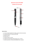
![User's Manual AH-480 Series [Machine / Software]](http://vs1.manualzilla.com/store/data/006867875_1-b2cd01726e15f409a063f19433f9385d-150x150.png)