1
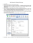
DEKTAKXT
STYLUS PROFILER
INSTALLATION AND
MAINTENANCE MANUAL
P/N 980-389
©2011, Bruker Corporation
All rights reserved
Printed in the United States of America
May 31, 2011
COPYRIGHT NOTICE
The reproduction, transmission, or use of this document or its contents is not permitted without express
written authority. Offenders will be liable for damages. All rights reserved.
All configurations and specifications are subject to change without notice.
TRADEMARK NOTICE
Vision is a registered trademark of Bruker Corporation. All other brand or product names are trademarks
or registered trademarks of their respective holders.
Bruker Nano Surfaces Business
2650 East Elvira Road
Tucson, Arizona 85756
Phone: (520) 741-1044
Fax: (520) 294-1799
TABLE OF CONTENTS
Safety Precautions . . . . . . . . . . . . . . . . . . . . . . . . . . . . . . . . . . . . . . . . . . . . . . . . . . . . . . 1
Unpacking the System . . . . . . . . . . . . . . . . . . . . . . . . . . . . . . . . . . . . . . . . . . . . . . . . . . . 1
Installing the Stylus Profiler . . . . . . . . . . . . . . . . . . . . . . . . . . . . . . . . . . . . . . . . . . . . . . . 6
Installing the Computer and Powering Up the System . . . . . . . . . . . . . . . . . . . . . . . . 15
Installing the Stylus. . . . . . . . . . . . . . . . . . . . . . . . . . . . . . . . . . . . . . . . . . . . . . . . . . . . . 22
Taking a Test Scan Measurement . . . . . . . . . . . . . . . . . . . . . . . . . . . . . . . . . . . . . . . . . 25
Electronically Configuring and Calibrating the Profiler. . . . . . . . . . . . . . . . . . . . . . . . 26
General Care and Maintenance . . . . . . . . . . . . . . . . . . . . . . . . . . . . . . . . . . . . . . . . . . . 26
Declaration of Conformity . . . . . . . . . . . . . . . . . . . . . . . . . . . . . . . . . . . . . . . . . . . . . . . 27
iii
SAFETY PRECAUTIONS
The DektakXT™ stylus profiler is designed to minimize potential health and safety hazards during
normal installation, operation, and maintenance activities. However, as with any mechanical system
that uses electrical energy and compressed air, it contains some physical and electrical hazards.
Potential safety hazards associated with the system are clearly identified in this DektakXT User
Manual. In addition, warning and safety labels have been placed on the system where there exists a
potential for personal injury or damage to the system.
You should be aware of these potential hazards and the controls used to minimize them. If you have
any questions on environmental, health, or safety-related issues associated with the DektakXT
system, contact Bruker Customer Service at 1-800-873-9750.
UNPACKING THE SYSTEM
IMPORTANT! Before you begin to unpack the DektakXT stylus surface system, make
sure that you have already reviewed the facility requirement. At a minimum, you will need an
AC power strip or three free power outlets that match the voltage requirements of your tool. If
you have purchased the optional vibration isolation feet or a vibration isolation table, you will
also need compressed air. If you purchased one of the vacuum sample fixtures (chucks), you
will need a source of vacuum. The DektakXT must sit on a sturdy workbench or vibration
isolation table. If you have any questions, call Bruker Customer Service at 800-873-9750.
The unpacked components of the DektakXT system (minus the environmental enclosure) appear on
the next page.
1
IMPORTANT! Be sure to retain and store all installation tools and shipping brackets for
possible future use.
To unpack the DektakXT stylus surface profiling system:
2
1
If you purchased the separate air isolation table, assemble it using the documentation inside the crate.
2
Move the shipping boxes next to the vibration isolation table or sturdy workbench on which the system will
finally sit. During the unpacking process, this the table or bench that will hold the environmental enclosure.
Have an another large table nearby to hold the computer components and DektakXT tool as they are
unpacked.
3
The shipping boxes for your DektakXT system appear in the picture that follows. You will have at least two
boxes—one for the environmental enclosure and one for the system itself. If you purchased the computer
and monitor from Bruker, you also will have one box for each of those items. If you purchased the air
isolation table, it will arrive in a wooden crate.
4
This is the box for the Dell computer.
5
After you open the box, you will see two smaller boxes on top of the computer. This first box contains all of
the cables, a mouse, documentation, backup CDs, and a shipping list. The smaller box contains the
keyboard.
6
Here is the monitor box.You will see the base of the stand as you open the box, as shown in the second
picture below. Carefully slide the foam packing material out of the box and set it on a table with the stand on
top. Remove the stand and set it aside.
3
4
7
Remove the top half of the foam, and you will see the monitor with the screen facing down. Take the
monitor out of the foam and set it on a clean, flat surface with the screen facing down. Attach the stand to
the monitor.
8
This is the environmental enclosure box. Although it is similar in size to the box that contains the DektakXT
stylus profiler, it is much lighter.
9
Remove the environmental enclosure and place it on a table near the final location of the DektakXT tool.
10
This is the box that holds the DektakXT stylus profiler. The tool is very heavy, so you will need two people
to lift it.
11
Lift the tool via both sides of the bridge. Be very careful not to touch the center where the head is located.
Place the tool on the surface that will be its final location—either a sturdy workbench or a vibration isolation
table. Make sure that there is plenty of front and back access room for performing the installation steps
outlined in the section that follows.
12
Remove and unpack the box containing one or more styli and the stylus exchange tool.
13
Remove the EMO box.
14
After you have unpacked all of the boxes, find the shipping checklist that was located in the computer
documentation and cable box. Do a complete inventory of all of the items shown on the checklist before
discarding the packing materials. If anything is missing, recheck the boxes. If you have any questions, call
Bruker Customer Service at 800-873-9750.
5
INSTALLING THE PROFILER
This section tells you how to install your new DektakXT stylus profiler. Make sure that the tool is
sitting on the system’s final location with ample access to both front and back. The environmental
enclosure should be sitting on a nearby table.
The first picture below shows a standard DektakXT system. The second picture shows the system
inside its environmental enclosure.
Hood-covered
measurement
head that
includes the
tower, camera,
illuminator, and
sensor head
Sensor head and
stylus
Block sample
fixture (chuck)
Manual samplepositioning stage
Scan stage
System base
Base foot
6
IMPORTANT! Be sure to save all of the shipping straps, brackets, and screws in case you
need to ship the tool to another facility in the future.
1
Loosen the orange Velcro shipping strap that is attached to the top of the stage. Then slide it out of the
slots in the two red shipping brackets and set it aside.
2
Remove the shipping bracket on the front of the stage by loosening the screw with a hex head wrench. The
wrenches are in the box that contains the computer documentation and cable (see the previous section).
Red plastic bracket on top of
the glass block on the front
of the tool
3
Retighten the screw, since it is part of the stage assembly.
4
On top of the glass block, you will see two red plastic brackets (see the picture above). One is located on
the front, and the other is located at the side. Carefully slide these brackets out, allowing the stage to rest
on the glass block. Make sure you don't leave any fingerprints or other debris on the glass. If you see any
dust on it, use clean air to blow it off.
5
Go to the back of the tool, where you will see the rear shipping bracket and a cable with a small black
plastic cable clamp. Remove the screw from the bracket and set the bracket aside.
7
8
6
Place the screw through the plastic cable clamp and back into the stage. Tighten it.
7
You will see two more shipping brackets on the front of the stage. Loosen the screws with a Phillips
screw driver, remove the brackets, and re-tighten the screws.
8
While you are at the back of the tool, attach the cables before removing the other shipping brackets. The
connector panel is located on the right side. There are three USB connectors, so find the three USB cables
that shipped with the system. Your cables may look slightly different from the ones shown below, but this
will not be a problem. Attach the cables to the tool.
9
9
10
Locate the power supply, a rectangular black box.
10
Attach the round connector to the power connector on the tool. Take care to rotate the connector properly,
so that the key fits.
11
The last cable is the tan-colored one that is attached to the EMO box. Plug it in and then return to the front
of the tool.
12
You will see a flat red plate above the stage This is the shipping bracket for the sensor head. Loosen the
two thumb screws and remove the plate.
11
12
13
If you have a wafer sample fixture (chuck), you will need to mount that next. Although yours may not look
exactly like this one, it will still mount with three screws.
14
Using the appropriate hex head wrench, attach the sample fixture as shown.
15
You will need to remove the head cover to gain access to the Z axis shipping bracket. Use care when
sliding the cover up, so as not to damage these cables.
16
Lift up the right side first; this will be easier.
17
Use the appropriate hex head wrench to remove the two silver screws.
18
Remove the Z-axis shipping bracket.
19
Use a small Phillips screwdriver to remove the two black screws from the bracket.
13
20
These two screws must be installed back in the holes in the Z axis bearing, as shown below.
21
Now replace the head cover, lowering the left side first.
22
Place the environmental over the fully assembled DektakXT tool. Make sure that the enclosure does not
touch the edges of the DektakXT itself.
NOTE – Always take measurements with the enclosure over the tool with the door closed,
since air currents and noise will affect measurements without this protection.
23
14
Pass the three power cables through the opening at the bottom of the back of the environmental enclosure.
INSTALLING THE COMPUTER AND POWERING UP THE
SYSTEM
1
Remove the software key from inside the Vision64 CD case.
2
Insert the key into one of the USB ports in the back of the computer.
15
16
3
Pick up the free ends of the three USB cables.
4
Insert them in the USB ports.
5
Set the keyboard and mouse next to the computer.
6
Insert these two USB cables in the remaining two ports on the back of the computer.
7
Locate the cable for the monitor.
8
Attach the cable to the connector on the video board in the computer. Be sure to tighten the screws.
17
9
10
18
Insert one of the power cords into the computer.
Insert another power cord into the receptacle in the power supply.
11
If you rotate the monitor sideways, you will be able to easily access the connectors. Attach the other end of
the cable and tighten the screws.
12
Insert the third power cord in the monitor, and then rotate the monitor back to its normal position.
13
If your system includes the air isolation feet, you will find the air line on the right side of the tool. Attach a
quarter-inch OD hard plastic air line between it and your compressed air source. Set the pressure to about
20 psi.
19
20
14
Plug all three power cords from the DektakXT tool into a power strip or three wall outlets. Turn on the power
supply switch.
15
On the EMO box, make sure the emergency red button is released by rotating it slightly clockwise. Then
press the white button. The light should turn on. If it does not, recheck all cables and make sure the fan on
the power supply is running.
Turn on the computer and monitor.
16
After the computer boots, the Vision64 application button
17
Click the Vision64 application button
18
As the software launches, the following events occur:
•
•
appears on the desktop and task bar.
to launch Vision64.
The head on the bridge moves to its upper limit. The system stops with the stylus in the Tower Up position.
The scan stage initializes.
The Vision64 Welcome screen appears, followed by the Vision64 Instrument tab, which includes the DektakXT
Live Video Display and Measurement Options window, as shown on the next page.
21
INSTALLING THE STYLUS
The DektakXT system comes with a tool that magnetically holds the stylus. This tool and one or
more styli (if ordered) were shipped in the same box that held the DektakXT profiler.
The following picture shows the stylus installed on the sensor head of the DektakXT tool.
.
To install the stylus on the sensor head:
1
22
Click the Tower Home button
on the toolbar at the top of the Live Video window.
2
On the DektakXT profiler, turn the brass thumb screw on the left side of the sensor head counter-clockwise
to loosen the sensor head magnetic shield. (The sensor head is located just beneath the hood-covered
measurement head).
Brass thumb screw
on sensor head
Magnetic shield
3
Slip the shield off the pin on the right side of the sensor head.
4
Carefully move the shield toward the front of the profiler and pull it off the sensor head.
Front of tool
5
Locate the stylus exchange tool that came in the same box as the DektakXT tool. If its green circle is
visible, rotate the thumbscrew in either direction to disengage the magnet and replace the green circle with
a gray one. (This means that the magnet is NOT engaged as shown below.)
Magnetic disk pad
Gray circle that
indicates that the
magnet is disengaged
Thumbscrew
Alignment pin
(one of five)
Channel for
holding the
stylus
23
6
Locate the case that holds the stylus that you want to install. After opening the case, use tweezers to gently
lift the stylus holding ONLY THE SILVER MAGNETIC DISK PAD AT ITS BACK END.
7
Align the magnetic disk pad of the stylus with the magnetic disk pad on the stylus exchange tool.
8
Seat the stylus in the channel on the exchange tool. The stylus arm should extend out through the front
channel on the exchange tool.
Magnetic disk pad on
the stylus exchange
tool
Magnetic disk pad
on the stylus
Green circle indicating
that the magnet is
engaged
9
10
24
Stylus arm
extended out
through front of
channel
Rotate the thumbwheel on the left side of the stylus exchange tool counterclockwise to display the green
circle and engage the magnet.
Place the stylus exchange tool underneath the sensor head on the DektakXT profiler. Holding the stylus
exchange tool by the sides, align the alignment pins on its top with the outside of the front of the sensor
head. Gently push up until the tool is flush with the bottom of the sensor head. The ridge at the back of the
stylus exchange tool must roughly line up with the back of the sensor head.
Sensor head
Alignment pin
Stylus tip
Stylus exchange tool
WARNING
Avoid any personal contact with the stylus arm or tip. This can result in
damage to the stylus.
11
Disengage the magnet by rotating the thumbwheel in either direction so that a gray circle replaces the
green one.
12
Lower the stylus exchange tool.
13
Position the magnetic shield on the thumb screw shaft on the left side of the sensor head and slip it over
the pin on the right side. As you do so, DO NOT push the magnetic shield up to the bottom of the sensor
head. This can restrict the full movement of the stylus arm.
14
Turn the brass thumb screw clockwise to attach the magnetic shield as shown below. Do not tighten the
screw—just “snug” it.
TAKING A TEST SCAN MEASUREMENT
Allow the system to warm up for approximately 15 minutes and then take a manual or automated
scan measurement according to the instructions in the DektakXT User Manual. If you are not satisfied
with the results, check the index of the User Manual or consult the DektakXT online Help. If these
steps do not solve your problem, contact Bruker Customer Service at 800-873-9750.
25
CONFIGURING AND CALIBRATING THE PROFILER
On the Instrument tab of the Ribbon in Vision64, click one of the following icons to open its
associated dialog box. For instructions on making the settings in each dialog box, see the DektakXT
User Manual and the DektakXT online Help.
GENERAL CARE AND MAINTENANCE
Follow these guidelines:
• Do not use lubricants on the stage leadscrews.
• Always position the sample so that the stylus is the only part of the stylus assembly that touches
the sample.
• Keep the environmental enclosure door closed both when the DektakXT system is in use and
when it is not.
• Never connect or disconnect any cables when the power is on.
• Do not lower the tower without the stage assembly in place.
• Do not move a sample during a scan measurement.
• Avoid vibration and shock during measurements. For example, ensure that an operator does not
bump a surface close to the profiler or the profiler itself during a measurement.
• Always raise the tower to the maximum vertical position when the system is not in use.
26