1
RN-WIFLYCR-UM-.01
RN-HID-UM
Bluetooth HID Profile
© 2012 Roving Networks. All rights reserved.
RN-HID-UM Version 1.1r 3/13/2012
www.rovingnetworks.com
USER MANUAL
1
RN-HID-UM-1.1r
OVERVIEW
Roving Networks Bluetooth modules support a variety of Bluetooth profiles, including human interface device
(HID), serial port profile (SPP), DUN, HCI, and iAP for use with iPad, iPod and iPhone devices. The Bluetooth HID
profile enables customers to develop wireless products such as computer keyboards and keypads, trackballs,
mice, and other pointing devices, and game controllers (gamepads, joysticks, steering wheels, etc.). Additionally,
Roving Networks has extended the basic HID capability to allow programmability and control of devices such as
the iPad.
The HID (Human Interface Device) profile defines the protocol between:
Device (HID)—Services human data input and output to and from the host.
Host—Uses or requests the services of a Human Interface Device.
The Bluetooth HID profile allows users to control the HID descriptor, which defines the device’s feature set, and
the HID report, which host uses to interpret the data as ASCII values, movement, etc. The HID report format
follows the standard universal serial bus (USB) HID protocol as to leverage existing host drivers.
NOTE: This user manual focuses specifically on HID. The Roving Networks Bluetooth Advanced User Manual
and Apple User Manual cover the functionality of all supported Bluetooth profiles. Because the HID
profile is derived from Roving Network’s standard firmware, many of the concepts and commands
found in the Advanced User Manual apply as well.
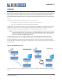
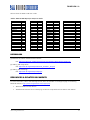
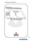
In a typical usage scenario such as a keyboard, a device using the Roving Networks Bluetooth HID profile
replaces the USB cable. In this case, the ASCII value of a key press is converted to a scan code in a raw HID
report that the Bluetooth module sends over the Bluetooth link to the host. The host driver software decodes
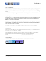
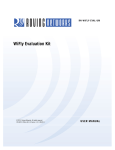
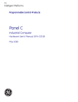
the raw HID report and passes the key values to the application running on the PC. Figure 1 shows some typical
HID environments.
Figure 1. Typical HID Environments
The type of HID device, such as a keyboard, mouse, or joystick, is defined by the HID descriptor in the raw HID
report.
www.rovingnetworks.com
2
RN-HID-UM-1.1r
FIRMWARE OVERVIEW
To use Roving Networks’ Bluetooth HID profile, you must use a special build of firmware, version 6.03 or later.
When you purchase a Roving Networks Bluetooth product, you must specify that you wish to use this firmware
version so that Roving Networks can load it into the module. The part numbers for ordering modules with the
HID profile are RN-41-HID and RN-42-HID.
NOTE: This user guide assumes the reader has an understanding of Roving Networks standard Bluetooth
firmware ASCII command interface and command set. It is strongly recommended that you refer to
the Bluetooth Advanced User Manual prior to reading this document.
Operational Modes
Roving Networks Bluetooth modules operate in two modes: data mode (default) and command mode. While in
data mode, the module is essentially a data pipe. When the module receives data, it strips the Bluetooth headers
and trailers and passes the user data to the UART. When data is written to the UART, the module constructs the
Bluetooth packet and sends it out over the Bluetooth connection. Thus, the entire process of sending/receiving
data to the host is transparent to the end microprocessor.
You configure the module by putting it into command mode and sending ASCII commands over a serial port or
the Bluetooth link. Once you change the configuration parameters, they persist until changed or you perform a
factory reset. You enter command mode by opening a terminal emulator and sending the string $$$ to the
module. You can connect to the module remotely over Bluetooth or via a computer. When you send $$$ the
module returns CMD, indicating that it is in command mode.
Once the module is in command mode, you can send configuration commands to it via the terminal. When you
enter a valid command, the adapter returns AOK. It returns ERR for an invalid command and ? for unrecognized
commands. Type h <cr> to see a list of commands, and d <cr> to view a summary of the adapter’s current
settings. To return to data mode, type --- <cr> or reset the device and re-connect.
Profile Configuration
The HID firmware supports Bluetooth HID and SPP. You switch between these profiles using ASCII commands. In
firmware version 6.10 and higher, the SPP profile is enabled by default. There are two ways to switch the
profile.
1.
Using PIO 11: On power up PIO 11 is sampled and if HIGH, HID profile is selected. Otherwise the profile
stored in flash is used (requires bit 9 to be set in the HID flags register. This is set by default).
2.
Using command mode: To switch between HID and SPP, use the following commands:
S~,6
// Enables HID profile
R,1
// Reboot to use HID profile
To switch back to SPP, use the following command:
S~,0
// Enables SPP protocol
R,1
// Reboot to use SPP
www.rovingnetworks.com
3
RN-HID-UM-1.1r
Device Discovery & Pairing
Since the Roving modules default to SPP, they will show up as “FireFly-ABCD” upon power up, where ABCD are
the last four digits of the MAC address. However, if the profile is changed to HID using the commands described
above, the modules default to a HID keyboard and is discoverable with the name “FireFly-ABCD”, where ABCD
are the last four digits of the MAC address. You can change the device type by setting the descriptor type using
the HID flags register.
After first pairing the host to a device with the Bluetooth HID module, the host initiates a connection. However,
if the initial connection is broken, as the case when the power is cycled, the device must re-connect to the host.
(The host will not initiate a connection.)
Using DTR mode 4 (default) or pairing mode 6 allows the module to auto-connect back to the last paired host.
Alternatively, you can reconnect by sending the C command from command mode.
Quiet Mode
Quite mode causes the device to be non-discoverable and non-connectable temporarily. This command does not
survive power cycle.
With firmware version 6.10 and higher, the Q command now has 3 settings that have different responses as
follows:
Q,0
// The module is discoverable and able to connect
Q,1
// The module is not discoverable and not able to connect
Q,2
// The module is able to connect but is not discoverable
Authentication
With firmware version 6.10 and higher, SA is 2 bits. It can have the values 0, 1, 2, or 4, depending on the mode
desired.
SA,0
// With this mode, the module uses Bluetooth version 2.0 NO encryption (open mode). This
mode is useful for legacy devices that do not need security. This mode is the same as in
firmware version 4.77. For this mode to work, both devices must support open mode. If either
device requests authentication, the PIN code will be required.
SA,1
// In Bluetooth version 2.1, the default is keyboard I/O mode (which is considered as a secure
mode). For Android devices, the user is prompted with a 6-digit code and is asked to verify
that the code matches on the module. Because the module cannot display a code, simply press
OK or Yes on the remote device to authenticate.
SA,2
// This mode corresponds to Bluetooth version 2.1 Secure Simple Pairing (SSP), or just works
mode. This mode works with iPhones and PCs, however it may not work appropriately with
some Android devices.
SA,4
// This mode is PIN code mode, which forces Bluetooth version 2.0 PIN code authentication.
The functionality is similar to firmware version 4.77.
www.rovingnetworks.com
4
RN-HID-UM-1.1r
Encryption
In firmware version 6.10 and higher, encryption is always enabled. In prior versions of firmware, you used the SE
command to turn on encryption. Refer to “Creating a Custom UUID” for more information on the SE command
functionality in firmware version 6.10 and higher.
Creating a Custom UUID
In firmware version 6.10 and higher, the SE command, SE,<1 – 16>, is used to set the UUID (E stands for
extended UUID). The GE command displays the extended UUID.
This feature applies to Roving Networks’ modules when configured in SPP profile mode. Using this feature the
Roving Modules can connect back to the remote device when it is range. This features is used primarily for
smartphones and tablets based on Android OS.
With this feature, you can set a custom UUID for connecting back to an Android device. Android phones run an
audio gateway that always attempts to grab a connection when it comes in from a remote Bluetooth device such
as the Roving Networks module. With the SE command, you can register a custom UUID, which ensures that
ONLY your app on the Android device obtains the connection when it comes in.
The default SSP UUID is 0000110100001000800000805F9B34FB
You can modify a subset of the UUID; the bytes are changed from left to right. For example, if the UUID is:
0000110100001000800000805F9B34FB
Typing the command SE,ABCD <cr> changes the first 2 bytes resulting in:
ABCD110100001000800000805F9B34FB
The command has three short forms:
SE,S
// Loads the default SPP UUID = 0000110100001000800000805F9B34FB
SE,I
// Loads the iPhone UUID = 00000000DECAFADEDECADEAFDECACAFE
SE,C
// Loads the custom UUID = EE286EA0000111E1BE500800200C9A66
www.rovingnetworks.com
5
RN-HID-UM-1.1r
HID Flag Register
The HID flag register is a bit-mapped reregister that is configured while in command mode. To set the register,
use the SH, <value> command, where <value> is a 4-character hex word. The GH command returns the current
value of the register. The default factory setting is 0200, which corresponds to a keyboard.
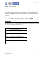
Table 1 shows the HID flag register bits; currently only the lower 9 bits are defined.
Table 1. HID Flag Register Bits
9
8
Force HID mode if
GPIO11 is high on
power-up.
Toggle virtual
keyboard on iOS
when first
connected.
7..4
Descriptor type:
0 = Keyboard
1 = Game Pad
2 = Mouse
3 = COMBO
4 = JOYSTICK
5 = DIGITIZER
6 = SENSOR
7 = USE CFG
8-16 = Reserved
3
Send output reports
over UART.
2..0
Indicates number of
paired devices to which
the module can
reconnect.
Bit 9
Bit 9 is an enable bit that overrides the profile selection mode. When this bit is set, the firmware checks the level
of GPIO11 on power up; if it is high, the module switches to HID mode. With this bit, you can set the module’s
default profile to SPP mode, allowing SPP and remote configuration (for example from Bluetooth clients with
SPP). Then, you can use GPIO11 to override SPP mode and enable HID mode.
Bit 8
Bit 8 enables the toggling of the virtual keyboard on iOS devices.
Bits 7-4
Bits 7 through 4 control the following settings:
The COD that is advertised by the module.
The HID report descriptor and the available reports.
Bit 3
Bit 3 enables output reports, which are sent by the host to the device over Bluetooth to the UART. These reports
are a feedback mechanism to the embedded microcontroller. The output record is formatted as:
<start>
<number of
bytes>
0xFE
1–8
<report>
data
For example, the HID keyboard output reports the keyboard LED status as:
www.rovingnetworks.com
6
RN-HID-UM-1.1r
0xFE
0x2
0x1 <LED status byte>
Bits 2-0
Bits 2 through 0 define the number of paired hosts to which the module attempts to reconnect after power up.
After each successful pairing, the link key is stored in the Bluetooth module. Up to eight paired link keys are
stored in FIFO fashion. Upon power up, the module tries to connect to the most recently paired device. If it is
not found, the module attempts to connect to the next N hosts depending upon the settings of bits 2-0 in the
HID register.
For example:
To set the device as a mouse, use SH,0220.
To set the device as a combo device (keyboard + mouse + consumer) , use SH,0230.
HID REPORTS
The module interprets input on the UART and generates an HID report that is sent over the Bluetooth link to the
host. Input to the module is interpreted as shown in Table 2.
Table 2. Data Interpretation
Binary Input
Function
0
Disconnect if connected from the host.
0x1 - 0xF
Converted to special keys like home, page up, backspace, etc.
0x10 - 0x7E
Translation mode: printable ASCII characters.
0x7F
Toggle virtual keyboard on iPhone.
0x80 - 0xDF
Interprets input as actual scan code.
0xE0 - 0xE7
Sends modifier keys Left Shift, Left Alt, Right Shift, etc.
0xE8 - 0xEF
Interprets input as actual scan code.
0xF0 - 0xFC
Reserved for custom reports.
0xFD
Raw mode: input is RAW report.
0xFE
Interpretive mode: input is shorthand report.
0xFF
Sends output report to UART.
www.rovingnetworks.com
7
RN-HID-UM-1.1r
Raw Report Mode
The start byte 0xFD indicates a raw HID report. In the Bluetooth module, the start byte is stripped and the
following bytes are sent without interpretation. The Raw HID report consists of a start byte, length, descriptor
type (which defines the type of HID device), and data specified in scan codes or encoded values. The format of
the data depends on the descriptor type. HID reports are sent one report at a time.
The raw report format is:
Start
(1Byte)
Length
(1 Byte)
Descriptor
(1 Byte)
Data
Length – one Byte for the descriptor
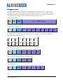
The keyboard report format is:
0xFD
9
1
Modifier
Scan
code 1
0x00
Scan
code 2
Scan
code 3
Scan
code 4
Scan
code 5
Scan
code 6
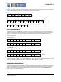
The modifier byte is a bit mask interpreted as shown below. For example, you can use 0x2 or 0x20 to turn a
lower case a into an upper case A.
Bit 7
Bit 6
Bit 5
Bit 4
Bit 3
Bit 2
Bit 1
Bit 0
Right
GUI
Right
Alt
Right
Shift
Right
Ctrl
Left
GUI
Left
Alt
Left
Shift
Left
Ctrl
The mouse raw report format is:
0xFD
5
2
Buttons
X-stop
Y-stop
Wheel
The consumer report format in keyboard or combo mode is:
0xFD
3
3
Data Byte
Data Byte
Not used
Buttons
X1
The joystick format is:
0xFD
6
www.rovingnetworks.com
Y1
X2
Y2
8
RN-HID-UM-1.1r
In combo mode, it is possible to send both for a keyboard and mouse HID reports. In this case, if you wanted to
enter an A and move the mouse you can use either of the following methods:
A:
0XFD
0x05
0x02
0x00
0x20
0x20
0x00
or
0xFD
0x9
0x1
0x2
0XFD
0x5
0x2
0x00
0x0
0x04
0x20
0x0
0x20
0x0
0x0
0x0
0x0
0x0
0x0
0x0
0x00
HID Translation Mode
Translation mode is the simplest way to send HID reports for printable ASCII characters. When the Bluetooth
module’s UART receives a printable ASCII value, it is converted into a keyboard raw HID report. Two reports are
sent for each character; the first report indicates that the key is pressed and the second indicates that it is
released. For example:
a is translated into :
0xFD
0x09
0x01
0x00
0x00
0x04
0x00
0x00
0x00
0x00
0x00
Key Press
0xFD
0x09
0x01
0x00
0x00
0x00
0x00
0x00
0x00
0x00
0x00
Key Release
A is translated into:
0xFD
0x09
0x01
0x02
0x00
0x04
0x00
0x00
0x00
0x00
0x00
Key Press
0xFD
0x09
0x01
0x00
0x00
0x00
0x00
0x00
0x00
0x00
0x00
Key Release
Notice that the scan code for A is the same as the previous raw report except the modifier byte indicates the left
Shift key is pressed. If multiple scan codes are sent, the modifier applies to all of them.
Keyboard Shorthand Mode
The Roving Networks HID profile supports shorthand for implementing keyboards. The advantage of this mode
is that multiple keyboard keys can be sent with minimal characters over the UART, which optimizes bandwidth
because the module does not have to send a keyboard report. Shorthand reports start with 0xFE and have
variable length. The shorthand format is:
www.rovingnetworks.com
9
RN-HID-UM-1.1r
0xFE
Length
Scan
Code 1
Modifier
Scan
Code 2
Scan
Code 3
Scan
Code 4
Scan
Code 5
Scan
Code 6
where Length = 0, 2, 3, 4, 5, 6, or 7, depending on how many keys are sent.
For example, shorthand for the a, b, and c keys is:
0xFE
0x04
0x00
0x04
0x05
0x06
This equivalent to a raw HID report of:
0xFD
0x09
0x01
0x00
0x00
0x04
0x05
0x06
0x00
0x00
0x00
Shorthand to release all three keys is:
0xFE
0x0
Special Reports & Modes
This section describes special modes and reports, including output reports, virtual keyboards, a key-map register,
etc.
Output Reports
Because the host controls the modifier keys’ state, the HID device must be able to request the current status.
The output report code 0xFF is reserved to return the current status of the Caps Lock, Num Lock, and Scroll Lock
keys over the UART. Because an HID device can only toggle these keys, it tells the device the state of the keys.
This functionality is particularly useful when multiple HID devices are in the system and the Bluetooth device
needs to update the state of these keys. The format is sent as:
0xFF
Status
Byte
Table 3 shows the status byte definitions.
Table 3. Status Byte Definitions
Key
Status Bit
Num Lock
1
Caps Lock
2
Scroll Lock
4
www.rovingnetworks.com
10
RN-HID-UM-1.1r
Apple Virtual Keyboard
When the module is connected to an iOS device, the virtual keyboard is hidden. However, in some applications it
is useful or required to display the keyboard for data entry on the touch screen of the iOS device. Toggling
GPIO9 displays or hides the virtual keyboard. GPIO9 must go from low to high for at least 200 ms for the toggle
to occur.
NOTE: The virtual keyboard toggle must be enabled in the HID flag register for this feature to work.
Key Map Register
This register allows you to replace any ASCII code with another ASCII code. It is useful in cases where you want
to toggle special keys that the device cannot generate. For example, the touch keyboard on an iOS device is
0x7F, but the device cannot generate 0x7F.
If the register is non-zero, the upper byte is the key to replace, and the lower is the replacement. The command
to set the register is S=, < value>, where <value> is a 4-character hex word. To obtain the current value of the
register, use the G= command. (The value also shows up in the advanced settings using the E command.) The
default factory setting is 0000 (not enabled).
For example, to use the tilda (~), which is 0xfe, to toggle the keyboard, enter the command S=,7e7f.
Disconnect Key
A special hex key value 0x00 (zero) causes a Bluetooth disconnect, which allows you to control the connection
by sending a single key. To disconnect, send 0x0.
Combining the disconnect feature with the key map register, any key can be used as a disconnect key. For
example to set the capital Z key (hex 5A) as the disconnect key, use the following command:
S=,5A00
// Map Z key as the disconnect key
Consumer Report
You can use a HID raw report to send additional keys as a consumer report. The format is:
0xFD
3
www.rovingnetworks.com
3
Low Byte
High Byte
11
RN-HID-UM-1.1r
Table 4 shows the data byte format.
Table 4. Data Byte Format
Consumer Key Function
Report Bit
AC Home
0x1
AL Email Reader
0x2
AC Search
0x4
AL Keyboard Layout (Virtual Apple Keyboard Toggle)
0x8
Volume Up
0x10
Volume Down
0x20
Mute
0x40
Play/Pause
0x80
Scan Next Track
0x100
Scan Previous Track
0x200
Stop
0x400
Eject
0x800
Fast Forward
0x1000
Rewind
0x2000
Stop/Eject
0x4000
AL Internet Browser
0x8000
For example, to raise the volume, send:
0xFD
0x03
0x03
0x10
0x00
To release the key, send:
0xFD
0x03
0x03
www.rovingnetworks.com
0x00
0x00
12
RN-HID-UM-1.1r
SCAN CODE TABLES: UART (ASCII) TO HID REPORT
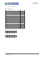
Table 5 shows the UART-to HID input conversion.
Table 5. UART-to-HID Scan Code
UART Input
0
1
2
3
4
5
6
7
8
9
10
11
12
13
14
15-26
27
28
29
30
31
32-126
127
0x80-0xDF
0xE0
0xE1
0xE2
0xE3
0xE4
0xE5
0xE6
0xE7
0xE8-0xEF
0xF0-0xFC
0xFD
0xFE
0xFF
HID Code
NA
0x49
0x4A
0x4B
0x4C
0x4D
0x4E
0x4F
0x2A
0x2B
0x28
0x50
0x51
0x28
0x52
0x3A-45
0x29
0x39
0x47
0x48
0x53
0x65
0x80-0xDF
0xE0
0xE1
0xE2
0xE3
0xE4
0xE5
0xE6
0xE7
0xE8-0xEF
Reserved for future
www.rovingnetworks.com
HID Function
Disconnect if Connected
Insert
Home
Page up
delete
end
Page down
Right arrow
Backspace
TAB
Enter
Left arrow
Down arrow
Enter
Up arrow
F1 - F12
Escape
Caps lock
Scroll lock
Break-pause
Num lock
Printable ASCII characters
Toggle iPhone virtual keyboard
Sends actual scan code
Left Control
Left Shift
Left Alt
Left GUI
Right Control
Right Shift
Right Alt
Right GUI
Sends actual scan code
Custom reports
Raw report
Shorthand report
Sends output report to UART
13
RN-HID-UM-1.1r
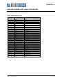
Table 6 shows the ASCII to HID scan codes.
Table 6. ASCII to HID Report (to Host) Scan Codes
ASCII
System Power
System Sleep
System Wake
No Event
Overrun Error
POST Fail
ErrorUndefined
aA
bB
cC
dD
eE
fF
gG
hH
iI
jJ
kK
lL
Code
81
82
83
00
01
02
03
04
05
06
07
08
09
0A
0B
0C
0D
0E
0F
ASCII
mM
nN
oO
pP
qQ
rR
sS
tT
uU
vV
wW
xX
yY
zZ
1!
2@
3#
4$
5%
Code
10
11
12
13
14
15
16
17
18
19
1A
1B
1C
1D
1E
1F
20
21
22
ASCII
6^
7&
8*
9(
0)
Return
Escape
Backspace
Tab
Space
-_
=+
[{
]}
\|
Europe 1
;:
‘“
,<
Code
23
24
25
26
27
28
29
2A
2B
2C
2D
2E
2F
30
31
32
33
34
36
ASCII
.>
/?
Caps Lock
F1
F2
F3
F4
F5
F6
F7
F8
F9
F10
F11
F12
Print Screen
Scroll Lock
Break (Ctrl-Pause)
Pause
Code
37
38
39
3A
3B
3C
3D
3E
3F
40
41
42
43
44
45
46
47
48
48
REFERENCES
[1] Bluetooth SG, Human interface Profile overview
URL: https://www.bluetooth.org/Building/HowTechnologyWorks/ProfilesAndProtocols/HID.htm
[2] USB.org, HID usage tables
URL: http://www.usb.org/developers/devclass_docs/Hut1_12v2.pdf
[3] USB.org, HID technology
URL: http://www.usb.org/developers/hidpage/
RESOURCES & RELATED DOCUMENTS
For more information, refer to the following sources, which are available on the Support page on the Roving
Networks website at http://www.rovingnetworks.com/support.php:
Bluetooth Advanced User Manual
iAP Bluetooth Evaluation Kit for Developing Accessories Compatible with iOS Devices User Manual
www.rovingnetworks.com
14
RN-HID-UM-1.1r
KNOWN ISSUES
The HID profile does not seem to always work with the BlueSoleil stack.
RELEASE NOTES
Version 6.10 2/17/12
Added additional functionality to the Q command to enable/disable device discovery and ability to
connect.
Added authentication modes: open mode, keyboard mode, SSP mode, and PIN code mode.
Encryption is enabled by default and cannot be disabled.
Added the ability to store a custom UUID in the device.
www.rovingnetworks.com
15
RN-HID-UM-1.1r
NOTES
www.rovingnetworks.com
16
RN-HID-UM-1.1r
Copyright © 2012 Roving Networks. All rights reserved. Roving Networks is
a registered trademark of Roving Networks. Apple Inc., iPhone, iPad, iTunes,
Made for iPhone are registered trademarks of Apple Computer.
Roving Networks reserves the right to make corrections, modifications, and
other changes to its products, documentation and services at any time.
Customers should obtain the latest relevant information before placing
orders and should verify that such information is current and complete.
Roving Networks, Inc.
102 Cooper Court
Los Gatos, CA 95032
+1 (408) 395-5300
www.rovingnetworks.com
www.rovingnetworks.com
Roving Networks assumes no liability for applications assistance or
customer’s product design. Customers are responsible for their products and
applications which use Roving Networks components. To minimize customer
product risks, customers should provide adequate design and operating
safeguards.
Roving Networks products are not authorized for use in safety-critical
applications (such as life support) where a failure of the Roving Networks
product would reasonably be expected to cause severe personal injury or
death, unless officers of the parties have executed an agreement specifically
governing such use.
17