1
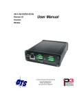
AN-X-ABRIO-SCAN
Remote I/O
User Manual
Scanner
Module
Quest Technical Solutions
4110 Mourning Dove Court
Melbourne FL 32934
321 757-8483
www.qtsusa.com
Page II AN-X-ABRIO-SCAN
Throughout this manual we use notes to make you aware of safety
considerations.
Identifies information about practices or circumstances that can lead to
personal injury or death, property damage, or economic loss.
These warnings help to:
WARNING!
IMPORTANT!
TIP
•
identify a hazard
•
avoid the hazard
•
recognize the consequences
Identifies information that is especially important for successful
application and understanding of the product.
Identifies information that explains the best way to use the
AN-X-ABRIO-SCAN
Microsoft is a registered trademark of Microsoft Corporation.
Windows, Windows 95, Windows NT, Windows 2000, Windows XP and Vista are trademarks of
Microsoft Corporation.
ControlLogix, RSLinx and RSLogix 5000 are trademarks of the Allen-Bradley Company, Inc.
April 2009
AN-X-ABRIO-SCAN MODULE OVERVIEW
1
Hardware Features
2
Package Contents
2
Modes of Operation
3
INSTALLATION
4
Prevent Electrostatic Discharge
4
Power
4
Cabling and Termination
4
Ethernet Cabling
5
Software Installation
6
QUICK START
7
ETHERNET CONFIGURATION
8
Ethernet Configuration
Standalone Computer
8
13
Reconfiguring an AN-X from an Unknown State
18
A Note on AN-X Names
18
CONFIGURING THE REMOTE I/O SCANNER
20
AnxAbioCfgScan Software
20
Configuring a Remote I/O Network
20
Baud Rate
20
Configuring Racks
Manually Adding Racks
Autoconfiguration
Resizing Racks
Deleting Racks
21
22
23
24
24
Block Transfer Modules
25
AN-X-ABRIO-SCAN Page iii
Mapping the I/O Data
Automatic Mapping
Manual Mapping
Clearing Mappings
What gets mapped
28
28
28
29
30
Uploading and Downloading Configurations
35
Saving Configurations
35
Aliases
36
Archiving Configurations
File/Archive Templates
File/Archive Template Check
38
38
38
CONFIGURING THE AN-X MODULE IN RSLOGIX 5000
39
Input Only Connections
41
ControlLogix Aliases
44
Using the ControlLogix Log
45
SCANNING REMOTE I/O
46
Required Connections
46
Scan Mode: program/run
46
Executing Block Transfers
Automatic
Semi-Automatic
Manual
Inhibiting Automatic Block Transfers
46
46
46
47
47
Monitoring operation
Discrete Inputs and Outputs
Block Transfers
Rack Status and Diagnostic Counters
Mapping Diagnostic Counters
Module Logs
47
47
49
52
54
55
BLOCK TRANSFER MODULE TEMPLATES
56
Description
56
Note
56
April 2009
Page iv AN-X-ABRIO-SCAN
Block Transfer Lengths
57
Default Configuration Data
57
Parameters
57
Aliases
59
USING ANXINIT
60
AnxInit Log
60
Locating Available AN-X Modules
61
Selecting an AN-X
62
Set AN-X IP Configuration
63
Restart an AN-X
64
AN-X Info
64
Read Kernel Parameters
65
Run Config Mode
65
Update AN-X Flash
65
Update Firmware
Firmware Update Wizard
Update Firmware Command
66
66
70
Patch Firmware
70
USING THE WEB INTERFACE
72
Log Files
System Error Log
System Info Log
ControlLogix Log
View All Logs
73
73
73
73
73
Administration Menu
Browse File System
AN-X IP Configuration
Archive Configuration
Check AN-X Load
Restart AN-X Module
73
73
74
75
77
78
April 2009
AN-X-ABRIO-SCAN Page v
TROUBLESHOOTING
79
LEDs
Ethernet LEDs
SYS LED
NET LED – Network Status
79
79
79
80
UPDATING THE FIRMWARE
81
Reading Version Numbers
81
Obtaining the Latest Software
81
APPENDIX: SCANNER CONFIGURATION FILE FORMAT
82
SPECIFICATIONS
84
SUPPORT
85
April 2009
AN-X-ABRIO-SCAN Module Overview
The AN-X-ABRIO-SCAN communications module connects a
ControlLogix PLC or other device to an Allen-Bradley remote I/O
network.
The module acts as a scanner on the remote I/O network, reading inputs
and writing outputs.
It supports up to 32 adapters, rack numbers from 0 to 76 octal, any
combination of partial racks and all remote I/O baud rates.
It also supports block transfer reads and writes at all possible locations
on these racks.
A ControlLogix processor communicates with the module using
scheduled connections over Ethernet, to read inputs from the remote I/O
network and write outputs.
The module is supplied with a Windows utility, AnxAbRioScanCfg, for
configuring and monitoring the remote I/O network and mapping the
remote I/O data to ControlLogix scheduled data
The AN-X-ABRIO-SCAN module also has a web interface for
monitoring logs and performing administrative functions. You can
communicate with the module using any standard web browser such as
Internet Explorer.
The module firmware can be updated over Ethernet using the Windows
utility AnxInit. Refer to page 80 for details.
Page 2 AN-X-ABRIO-SCAN
Hardware Features
The module has:
•
LEDs to indicate the status of the connection to the Ethernet (100
and Link/Act)
•
a LED to indicate the module’s internal state and the state of
communication with the ControlLogix (SYS)
•
a LED to indicate the state of communications on the Remote I/O
network (NET)
•
an Ethernet connector
•
a power connector
•
a 3-pin Phoenix connector to connect to the remote I/O network
A watchdog timer is implemented in the module’s hardware. If the
firmware does not kick the watchdog within the timeout period the
watchdog times out and places the module into a safe fatal failure state.
A jabber inhibit timer is implemented in the module’s hardware. If the
network transmitter is on longer than 150% of the longest network
frame time, the transmitter is forced off and the module is placed into a
safe fatal failure state.
Package Contents
•
AN-X-ABRIO-SCAN module
•
CD containing software and documentation
•
rubber feet for desktop use
April 2009
AN-X-ABRIO-SCAN Page 3
Modes of Operation
There are three AN-X modes of operation:
•
Boot mode. The AN-X is running its low level startup firmware.
•
Configuration mode. This is the mode when you are updating the
firmware in the AN-X.
•
Production mode. This is the normal runtime mode of operation.
April 2009
Page 4 AN-X-ABRIO-SCAN
Installation
Prevent Electrostatic Discharge
The module is sensitive to electrostatic discharge.
WARNING!
Electrostatic discharge can damage integrated circuits or
semiconductors. Follow these guidelines when you handle the module:
•
Touch a grounded object to discharge static potential
•
Do not touch the connector pins
Power
AN-X requires a DC power input of anywhere from 12 to 24 VDC.
Left to right the pins on the power connector are chassis ground, negative
voltage and positive voltage.
The chassis ground should be connected.
Power consumption is 300 mA @ 12VDC or 150 mA @ 24VDC.
The part number for the power connector is Phoenix MSTB
2.5/3-ST-5.08
Contact QTS if you need a suitable wall adapter.
Cabling and Termination
Follow Allen-Bradley cabling recommendations for remote I/O. Refer to
Approved Vendor List for DH, DH+, DH-485, and Remote I/O Cables,
publication ICCG-2.2, February 1996.
From left to right on the AN-X module, the network connections should
be line 1, shield, line 2.
April 2009
AN-X-ABRIO-SCAN Page 5
Terminate both ends of a remote I/O network by using external resistors
attached to the physical ends of the network. There should be two and
only two terminators on the network.
Use 82 ohm resistors if the network operates at 230.4 kbps or if the
network operates at 57.6 kbps or 115.2 kbps and none of the devices in
the table below are present. The maximum number of physical devices
on the network is 32.
Use 150 ohm resistors if the network contains any of the devices in the
table below, or if the network operates at 57.6 kbps or 115.2 kbps and
you do not require the network to support more than 16 physical devices.
Device Type
Catalog Number
Series
Adapters
1771-AS
All
1771-ASB
Series A and B
1771-DCM
All
1771-AF
All
1771-AF1
All
Miscellaneous
Baud Rate
Maximum Cable Length
57.6 Kbaud
10000 ft
115.2 Kbaud
5000 ft
230.4 Kbaud
2500 ft
Ethernet Cabling
AN-X has a standard RJ-45 connector for connecting to Ethernet.
If you are connecting to the AN-X through a router or switch, use a
standard Ethernet cable.
If you are connecting directly to the AN-X module, use a crossover
cable.
April 2009
Page 6 AN-X-ABRIO-SCAN
Software Installation
You must uninstall any previous version of the software before you can
install a new version. Use the Windows Control Panel Add and Remove
Programs to remove the old version.
Insert the CD supplied with the AN-X module and run the program
setup.exe on the CD to install common AN-X components.
Run the program AnxAbRioSetup.msi in the AB\RIO folder to install the
components for the AN-X-ABRIO-SCAN
April 2009
AN-X-ABRIO-SCAN Page 7
Quick Start
Step Operation
See page
1
Install the AN-X Windows software
6
2
Power up the AN-X, connect it to Ethernet and use
AnxInit to assign it an IP address
8
3
Connect AN-X to the Remote I/O network
4
4
Use the AN-X Windows utility to autoconfigure
the remote I/O network and ControlLogix
configuration
23
5
Configure the AN-X in RSLogix 5000
39
6
Scan I/O, read inputs and write outputs
7
Create aliases for RSLogix 5000
44
8
Import the aliases into RSLogix 5000
44
9
Use the aliases to access data
April 2009
Page 8 AN-X-ABRIO-SCAN
Ethernet Configuration
The AN-X-ABRIO-SCAN module connects a device such as a
ControlLogix processor on Ethernet to scan an Allen-Bradley remote I/O
network.
Before you can use the AN-X-ABRIO-SCAN, you must configure its
network properties on Ethernet.
Ethernet Configuration
AN-X can be configured to use a static (unchanging) IP address or it can
be configured to obtain its IP address from a DHCP server.
Unless you have control of the DHCP server, in most applications you
will configure AN-X to use a static IP address. Otherwise the DHCP
server may assign a different IP address each time AN-X powers up, and
any software that accesses the AN-X module would have to be
reconfigured.
AN-X is shipped with DHCP enabled. If it finds a DHCP server on the
network, the DHCP server assigns it an IP address. You can use the
utility AnxInit to find the IP address that the DHCP server has assigned.
Select Utilities/Locate All AN-X Modules and AnxInit will locate the
AN-X and display its IP address.
If AN-X does not find a DHCP server within about three minutes of
starting up, it reverts to a temporary static IP address of 192.168.0.41 If
AN-X is using this temporary IP address, it repeatedly flashes the SYS
April 2009
AN-X-ABRIO-SCAN Page 9
LED red three times followed by a pause. If your computer is on the
same subnet, you can use the web interface to change the IP address of
the AN-X.
IMPORTANT!
Use this temporary IP address only for initial setup of AN-X. AN-X will
not function correctly for its intended purpose at the temporary IP
address.
If you are using multiple AN-X modules, configure them one at a time,
especially if there is no DHCP server on the network, since they will all
revert to the same temporary IP address when they fail to find a DHCP
server.
IMPORTANT!
If you are connecting AN-X to an existing Ethernet network, consult the
network administrator to obtain a static IP address for AN-X and to
obtain information about how you should configure AN-X.
IMPORTANT!
The AN-X must be on the local Ethernet (same subnet as your computer)
when you set its IP address.
You configure the Ethernet properties using the Windows utility AnxInit
supplied with AN-X or the AN-X web interface.
In AnxInit, use the Configuration/AN-X IP Settings command to start the
AN-X IP configuration wizard, which takes you step by step through the
IP configuration process.
Step 1
In step 1, you identify the AN-X you are configuring.
April 2009
Page 10 AN-X-ABRIO-SCAN
1. Select the Ethernet adapter that is connected to the AN-X. In most
cases there will be just one Ethernet adapter in the computer. The AN-X
must be on the same subnet as the computer.
2. Enter the MAC address of the AN-X you are configuring. This is
printed on the AN-X label. It consists of six pairs of hexadecimal digits,
separated by hyphens. In the example above, it’s 00-0c-1a-00-01-0d
If the AN-X is already online, you can obtain its MAC address using the
Utilities/Locate All AN-X Modules command.
3. Enter the IP address you intend the AN-X to use. In the example
shown, it’s 192.168.1.12
Step 2
In step 2, you choose a method of restarting AN-X to put it in boot mode.
April 2009
AN-X-ABRIO-SCAN Page 11
The preferred method is to cycle power on the AN-X. Select the first
option on the screen and click the Next >> button.
An alternative method, useful if the AN-X in not easily accessible, is to
send it a command over Ethernet. The AN-X must be powered on and
completely running for this method to work. For example, if this is the
first time you are configuring a new AN-X, allow sufficient time for it to
acquire an IP address from a DHCP server or to time out and use its
default IP address (about 3 minutes). Select the second option on the
screen and click the Next >> button.
Step 3:
Wait for AN-X to enter boot mode. While AnxInit is waiting, the
Next>> button is disabled. When AN-X is in boot mode, the Next>>
button is enabled.
April 2009
Page 12 AN-X-ABRIO-SCAN
If the AN-X does not enter boot mode within about 10 seconds, return to
the previous screens and check the entries.
The AN-X TCP/IP Configuration dialog appears.
Enter a Host Name for the AN-X. AN-X uses this name when it creates
aliases so give the AN-X a meaningful name that is unique on your
April 2009
AN-X-ABRIO-SCAN Page 13
network. This name is also used internally by AN-X and may be used to
identify the AN-X if you have a DNS server on your network. The name
can be from 1 to 31 characters long. It can contain alphanumeric
characters and a hyphen.
To configure the AN-X to obtain its IP address from a DHCP server on
the network, select Obtain an IP address automatically (DHCP)
To configure the AN-X to use a static IP address, select Use the
following Settings and enter:
•
the desired IP address for the AN-X.
•
the Subnet mask for the AN-X
•
the default gateway for your network.
You must enter a default gateway address that is valid for the subnet,
even if there is no device at the gateway address on the network.
Click OK to complete the configuration.
If you click Cancel, AN-X is left running the boot code. Use the
Utilities/Restart AN-X command to restart the AN-X in production mode.
Standalone Computer
Since you are connecting directly from the computer to AN-X, use a
crossover Ethernet cable.
The following instructions assume Windows XP. They also assume that
an Ethernet network card has been installed in the computer and that
AnxInit has been installed on the computer.
TIP
The parameters in this example will work when you set up any
standalone computer to work with AN-X.
First configure the computer to use a static IP address. From the Control
Panel, select Network Connections. Double click on Local Area
Connection (or whatever connection is being used for the AN-X)
April 2009
Page 14 AN-X-ABRIO-SCAN
Click the Properties button.
Double click on Internet Protocol (TCP/IP).
April 2009
AN-X-ABRIO-SCAN Page 15
In this example, we assigned the computer an IP address of 192.168.0.10
We set the Subnet mask to 255.255.255.0 (standard mask for the Class C
network address of 192.168.0.x).
We set the Default gateway to 192.168.0.1 (this address does not exist on
the Ethernet network but AN-X requires a valid default gateway entry).
Click OK to accept the settings
Connect the computer to AN-X using the crossover cable.
If this is the first time you have used the AN-X module, it will look for a
DHCP server on the network. It waits about three minutes, then reverts
to a default IP address of 192.168.0.41
Power up the AN-X and wait for the search for a DHCP server to time
out. When the search for a DHCP server times out, AN-X repeatedly
flashes the SYS LED red three times followed by a pause.
Run AnxInit. Select Utilities/Locate All AN-X Modules and confirm that
it finds the AN-X.
April 2009
Page 16 AN-X-ABRIO-SCAN
Select Utilities/Select An AN-X and enter the MAC Address and IP
address.
Click OK to accept the setting.
Select Utilities/AN-X IP Configuration.
April 2009
AN-X-ABRIO-SCAN Page 17
Enter an IP Address. In this case we chose 192.168.0.105
Enter the same Subnet mask and Default gateway that you entered for the
computer. The default gateway address does not exist on the network
but AN-X requires that the field have a valid entry.
Click Finish to accept the settings.
Select Utilities/Restart AN-X to restart AN-X with the new parameters.
When the AN-X has restarted (SYS LED is solid green), select
Utilities/Locate All AN-X Modules and confirm that the AN-X is found
with the new parameters.
April 2009
Page 18 AN-X-ABRIO-SCAN
Reconfiguring an AN-X from an Unknown State
It sometimes happens that an AN-X has been previously configured with
an IP address that causes it to be inaccessible on the current Ethernet
network. To reconfigure it to a known state, run the command
Configuration/AN-X IP Settings to start the AN-X IP Configuration
Wizard and reconfigure AN-X.
A Note on AN-X Names
You assign a name to the AN-X module in several places:
•
Ethernet hostname
•
name assigned to the ENBT module that the AN-X emulates in
RSLogix 5000
•
base tag name when exporting aliases from the configuration tool for
import into RSLogix 5000
•
name in the Module Properties dialog in the configuration tool
The first three names should all be the same. The name is first set when
you configure the Ethernet properties of the AN-X.
The name in the Module Properties dialog is not used elsewhere and does
not have to match the other names.
April 2009
AN-X-ABRIO-SCAN Page 19
April 2009
Page 20 AN-X-ABRIO-SCAN
Configuring the Remote I/O Scanner
AnxAbioCfgScan Software
The AN-X-AB-RIO-SCAN module is supplied with a Windows
configuration utility.
Use this configuration tool to:
•
Set the baud rate
•
Autoconfigure from an attached remote I/O network
•
Manually configure racks
•
Add and configure block transfer modules
•
Map I/O data to ControlLogix scheduled connections
•
Save and load configuration files
•
Download and upload configurations
•
Archive block transfer templates
•
Monitor diagnostics, rack status, block transfers and discrete data
Configuring a Remote I/O Network
Use the following steps to configure the AN-X-AB-RIO-SCAN:
1. Set the baud rate
2. Configure the racks, either manually or automatically
3. Add and configure block transfer modules.
4. Map the remote I/O modules to ControlLogix scheduled data
5. Download the configuration to the AN-X-AB-RIO.
Baud Rate
To set the network baud rate, first right click on the root of the network
tree.
April 2009
AN-X-ABRIO-SCAN Page 21
Select AN-X-AB-RIO Properties to display the AN-X-AB-RIO Module
Properties dialog box.
Select the Baud Rate from the list. Choices are:
Selection
Baud Rate, kbits/second
57k
57.6
115k
115.2
230k
230.4
The default baud rate is 57.6 Kbits/second.
Note: If you perform an autoconfiguration, the AN-X-AB-RIO
automatically detects the baud rate from an attached network.
The AN-X Name can be from 0 to 15 characters long. It is not used
elsewhere.
Configuring Racks
You can add racks manually or by autoconfiguring from an attached
remote I/O network.
April 2009
Page 22 AN-X-ABRIO-SCAN
Manually Adding Racks
To add a rack manually to the remote I/O configuration, first right click
on the root of the network tree.
Select Add Rack to display the Add/Resize Rack dialog box.
Select the Rack number (in octal), the Start I/O Group and the End I/O
Group for the rack you are adding and click OK.
To add a partial rack to an existing rack number, right click on the rack
and select Add Rack.
April 2009
AN-X-ABRIO-SCAN Page 23
The Add/Resize Rack dialog appears, with the rack number set.
Select the the Start I/O Group and the End I/O Group for the rack you are
adding and click OK.
Autoconfiguration
The AN-X-AB-RIO supports autoconfiguration, which automatically
detects the network baud rate and configures the racks on an attached
remote I/O network. You still have to add and configure block transfer
modules.
The controller with the connection to the AN-X-AB-RIO must be in
program mode when you perform an autoconfiguration.
To autoconfigure, select Configure/Autoconfigure
The AN-X-AB-RIO first detects the network baud rate, then sends
messages to all possible racks, builds a network configuration from the
replies it receives, and displays the network configuration.
Any configuration previously stored in the AN-X-AB-RIO is overwritten
by the data from the autoconfiguration.
April 2009
Page 24 AN-X-ABRIO-SCAN
Resizing Racks
To resize a rack, first right click on the rack in network tree.
Select Resize Partial Rack to display the Add/Resize Rack dialog box.
You cannot change the rack number when you resize a rack.
Select the Start I/O Group and the End I/O Group and click OK.
If resizing the rack results in an overlap with another rack, the resize will
fail and you will get an error message.
If resizing the rack results in deleting block transfer modules, you will be
given the option of cancelling or proceeding with the resize and deleting
the block transfer modules.
Deleting Racks
To delete a rack, right click on it in the network tree and select Delete
Rack(s).
April 2009
AN-X-ABRIO-SCAN Page 25
To delete a partial rack, right click on it in the network tree and select
Delete Partial Rack.
The program asks for confirmation before deleting.
Block Transfer Modules
To add a block transfer module, first expand the network tree to show the
location where you want to add the module.
April 2009
Page 26 AN-X-ABRIO-SCAN
Right click on the location where you want to add the module and select
Module Properties.
Select the Module Type from the list
April 2009
AN-X-ABRIO-SCAN Page 27
Most block transfer modules have parameters that you can select. Click
the Configure button to display a dialog box to configure the module.
For example, here is the configuration dialog for an 8-channel 1771-IFE
module.
Enter the configuration data and click OK.
Select how you want the block transfer to update. There are three update
modes: automatic, semi-automatic and manual.
Mode
Description
Automatic
AN-X-AB-RIO controls block transfer update
I/O module configuration data comes from AN-X
configuration tool
Semi-automatic
AN-X-AB-RIO controls block transfer update
I/O module configuration data comes from the
ControlLogix
Manual
ControlLogix controls block transfer update
I/O module configuration data comes from the
ControlLogix
For automatic and semi-automatic modes, enter the block transfer read
and write update rates, from 0 to 16383 ms. A rate of 0 means the ANX-AB-RIO will update the block transfer as fast as the remote I/O
network and the block transfer module allow.
For manual mode, enter the lengths of the block transfer read and write
data mapped to the ControlLogix.
April 2009
Page 28 AN-X-ABRIO-SCAN
Mapping the I/O Data
You must map the I/O data to locations in the ControlLogix scheduled
input and output data before you can scan the remote I/O network.
Unassigned I/O addresses are shown as xxxx in the network tree.
Automatic Mapping
To automatically map any unassigned data, select Map/Auto-map Any
Unassigned. The configuration tool maps all unassigned I/O to
scheduled inputs and outputs. It leaves any previously assigned address
unchanged.
To remap all data, select Map/Re-Map All. You are asked for
confirmation before the mappings ar reassigned.
Manual Mapping
To manually map discrete(rack) data, expand the network tree, right click
on the rack and select Rack Map Discretes – Assign Manually
For the inputs and outputs, select the ControlLogix scheduled block and
the offset within the block.
Click OK to accept the mapping.
April 2009
AN-X-ABRIO-SCAN Page 29
The configuration tool checks for overlaps with previously mapped data
and gives an error if it finds an overlap.
To manually map the data for a block transfer module, right click on the
module and select BT Module Clx Map – Assign Manually.
For the inputs and outputs, select the ControlLogix scheduled block and
the offset within the block.
Click OK to accept the mapping.
The configuration tool checks for overlaps with previously mapped data
and gives an error if it finds an overlap.
If there is insufficient space in the current block to map the data, the Data
Offset is blank and the OK button is grayed out. Change the block
number and select an offset.
Clearing Mappings
To clear all assigned mappings, select Map/Clear All Mappings.
To clear the mapping of the discrete data for a rack, right click on the
rack and select Rack Map Discretes – Clear.
April 2009
Page 30 AN-X-ABRIO-SCAN
The configuration tool asks for confirmation before it clears the
mapping.
To clear the mapping for a block transfer module, right click on the block
transfer module and select BT Module Clx Map – Clear.
The configuration tool asks for confirmation before it clears the
mapping.
What gets mapped
The following sections describe the data that gets mapped to
ControlLogix scheduled data.
Rack Discrete Data
The tables show the input and output data that gets mapped when you
map a rack.
April 2009
AN-X-ABRIO-SCAN Page 31
When you map any part of a rack to scheduled data, the structure that
gets mapped contains the data for the entire rack number. For example,
if rack 1 consists of just I/O groups 0 and 1 (a quarter rack), the entire
structure shown below is mapped when you map the rack. Similarly, if a
rack is made up of several partial racks, mapping any one of those partial
racks maps the structure for the entire rack; you do not need to map each
partial rack.
Discrete Input Data
Offset
Bit
Description
0
0
Communication Error first quarter (I/O Group 0-1)
1
Communication Error second quarter (I/O Group 2-3)
2
Communication Error third quarter (I/O Group 4-5)
3
Communication Error fourth quarter (I/O Group 6-7)
4-15
Reserved
1
0-15
Reserved (Pad for 32 bit alignment)
2-9
0-15
Discrete input data
The discrete read structure for a rack consists of 2 status words and 8
words of discrete input data.
Only bits 0 to 3 of the first word of status data are used. They consist of
error bits that are set if there is a communication error with a partial rack.
Bit 0 corresponds to a rack that starts at I/O group 0, bit 1 corresponds to
a rack that starts at I/O group 2, and so on.
The error bit is 1 if there’s an error scanning the rack or if the rack is
inhibited, and is 0 otherwise.
Words 2-9 contain the discrete input data for the rack. Words 2 and 3
contain the data for I/O groups 0 and 1 (first ¼ rack), words 3 and 4
contain the data for I/O groups 2 and 3 (second ¼ rack), and so on.
Discrete Output Data
Offset
Bit
0
0
Inhibit rack that starts at first quarter (I/O Group 0-1)
1
Inhibit rack that starts at second quarter (I/O Group 2-3)
2
Inhibit rack that starts at third quarter (I/O Group 4-5)
3
Inhibit rack that starts at fourth quarter (I/O Group 6-7)
4-15
Description
Reserved
April 2009
Page 32 AN-X-ABRIO-SCAN
Offset
Bit
Description
1
0-15
Reserved (Pad for 32 bit alignment)
2-9
0-15
Discrete output data
The discrete write structure for a rack consists of 2 control words and 8
words of discrete output data.
Bits 0-3 of the first word of control data are used to inhibit racks. Set bit
0 to inhibit the scan of the rack starting at I/O group 0; set bit 1 to inhibit
the scan of the rack starting at I/O group 2; and so on. Inhibiting a rack
stops all communications with that rack and all outputs revert to their
programed Last State.
Only the bit for the starting I/O group need to be set to inhibit the rack.
For example, if a rack is a full rack starting at I/O group 0, only bit 0
needs to be set to inhibit the scan of the rack.
Words 2-9 contain the discrete output data for the rack. Words 2 and 3
contain the data for I/O groups 0 and 1 (first ¼ rack), words 3 and 4
contain the data for I/O groups 2 and 3 (second ¼ rack), and so on.
Block Transfer Modules
The tables show the structures that get mapped to ControlLogix
scheduled input or output data when you map a block transfer module.
Even if a module has only a block transfer read or a block transfer write,
you should always map the module to both scheduled input and output
data, so that the control and status data gets mapped.
BT Control Read Structure
Offset
Bit
Description
0
0-7
BTR Update Counter (increments each time BTR executes,
range 0-255)
8-10
BTR Error Code
11
BTR.ERR, block transfer read error bit, see table of error
codes
12
BTR.DN, block transfer read done (manual mode only)
13-15
1
Reserved
0-7
BTW Update Counter (increments each time BTW executes,
range 0-255)
8-10
BTW Error Code, see table of error codes
11
BTW.ERR, block transfer write error bit
12
BTW.DN, block transfer write done (manual mode only)
13-15
Reserved
April 2009
AN-X-ABRIO-SCAN Page 33
Offset
Bit
2-n
0-15
Description
BTR Data (64 INTs max)
Offset 0 bits 0-7 contain a counter that increments each time a block
transfer read executes successfully on the remote I/O network. Based on
the configuration of the AN-X-AB-RIO and its RPI, the controller may
see this value increment by more than 1 count per program scan.
The AN-X-AB-RIO sets the BTR error bit, offset 0 bit 11, when an error
occurs executing a block transfer read. It clears the bit when the block
transfer read enable bit bit is reset in the coresponding BT Control Write
Structure.
When a block transfer read error occurs, offset 0 bits 8-10 contain an
error code (see table below).
When you execute a block transfer read in manual mode, the
AN-X-AB-RIO sets the done bit, offset 0 bit 12, to indicate that the
block transfer read executed successfully. It resets the bit when the
coresponding BTR.EN bit is reset in the BT write control file.
Offset 1 bits 0-7 contain a counter that increments each time a block
transfer write executes successfully on the RIO network. Based on the
configuration of the AN-X-AB-RIO and its RPI, the controller may see
this value increment by more than 1 count per program scan.
The AN-X-AB-RIO sets the BTW error bit, offset 1 bit 11, when an error
occurs executing a block transfer write. It clears the bit when the block
transfer write enable bit is reset in the coresponding BT Control Write
Structure.
When a block transfer write error occurs, offset 1 bits 8-10 contain an
error code (see table below).
When you execute a block transfer write in manual mode, the
AN-X-AB-RIO sets the done bit, offset 1 bit 12, to indicate that the
block transfer write executed successfully. It resets the bit when the
coresponding BTW.EN bit is reset in the BT write control file.
Word offsets 2-n contain the read data returned by the block transfer
module.
BT Control Write Structure
Offset
Bit
Description
0
0-5
BTR Length (1-63 word, 0 means BT Module decides)
6-7
Reserved
8
BTR.EN, block transfer read enable (manual mode only)
April 2009
Page 34 AN-X-ABRIO-SCAN
Offset
Bit
9
Description
BTR.CONT (manual mode only)
BT Inhibit (Automatic modes – inhibits config BTW, data BTW
and data BTR)
10-15
1
2-n
Reserved
0-5
BTW Length (1-63 word, 0 means BT Module decides)
6-7
Reserved
8
BTW.EN, block transfer write enable (manual mode only)
9
BTW.CONT, continuous mode (manual mode only)
10-15
Reserved
0-15
BTW Data (64 INTs max)
Offset 0 bits 0-5 contain the block transfer read length for manual mode
Offset 0 bit 8 contains the block transfer read enable bit for manual mode
block transfers.
Offset 0 bit 9 is used in two different ways:
in manual mode, this bit is the block transfer read continuous bit. If
this bit is set and the block transfer read enable bit is set, the
AN-X-AB-RIO re-enables block transfer reads when they have
executed successfully
in automatic and semi-automatic modes, this bit is used to inhibit all
block transfers to the I/O module
Offset 1 bits 0-5 contain the block transfer write length for manual mode.
Offset 1 bit 8 contains the block transfer write enable bit for manual
mode block transfers.
Offset 1 bit 9 is the block transfer write continuous bit for manual mode.
If this bit is set and the block transfer write enable bit is set, the
AN-X-AB-RIO re-enables block transfer writes when they have executed
successfully.
Word offsets 2-n contain the write data sent to the block transfer write
module.
Error Codes
Error Code
Description
0
OK
1
BTR/BTW request ignored by block transfer module
2
Block Transfer state mismatch
3-6
Reserved, not currently used
April 2009
AN-X-ABRIO-SCAN Page 35
Error Code
7
Description
Block transfer disabled
Required Connections
The configuration tool shows the ControlLogix connections to which
data has been mapped at the root of the network tree.
For each required connection, you must create a Generic module in the
ControlLogix configuration with that slot number. See page 39.
Required connections need not be contiguous.
In the example shown, data has been mapped to blocks 0 and 1 and so
connections 0 and 1 must exist in the ControlLogix in order for the
AN-X-AB-RIO to scan I/O.
Uploading and Downloading Configurations
To download a configuration to the AN-X-AB-RIO, select
Communication/Download Configuration or use the Download
Configuration to Module button on the toolbar
To upload a configuration from the AN-X-AB-RIO, select
Communication/Upload Configuration or use the Upload Configuration
from Module button on the toolbar
Saving Configurations
To save a configuration to disk, select File/Save or File/Save As.
April 2009
Page 36 AN-X-ABRIO-SCAN
Aliases
The configuration tool exports aliases for discrete and block transfer data
that can be imported into RSLogix 5000.
You should write control programs in terms of these aliases rather than
using absolute addresses. If the mapping of the I/O data changes, simply
reimport the new aliases and the control program will point to the new
data locations.
To export aliases, select Tools/Export Alias File…
Use the browse button to change the file location.
The Alias Prefix is used to distinguish between aliases for different
AN-X-AB-RIO modules. If you have more than one AN-X-AB-RIO in
the RSLogix configuration, assign each one a different Alias Prefix so
that the aliases for each module are unique.
The Base Tag identifies the AN-X the aliases are being created for. It
should match the name you give the emulated ENBT module in the
ControlLogix chassis. Refer to the Tags section in RSLogix 5000 to find
the format of the Base Tag
Check the Input Only box if you want aliases only for input data.
Check the Diagnostic Counters box if you want aliases for diagnostic
counters to be included in the file. These aliases contain only comments;
they do not contain alias names.
Click OK to create the alias file.
Alias Example
The remote I/O configuration contains a single quarter rack, rack 1,
starting I/O group 0.
April 2009
AN-X-ABRIO-SCAN Page 37
We export aliases from the configuration tool using the Alias Prefix
RIO_ and base tag ABRIOscan
The aliases that are created are:
Alias Name
Comment
Address
RIO_R01_STS
Rack-01 Status
ABRIOscan:0:I.Data[0]
RIO_R01_CTL
Rack-01 Control
ABRIOscan:0:O.Data[0]
RIO_I010
Rack-01 Grp-0
Discrete Input
ABRIOscan:0:I.Data[2]
RIO_O010
Rack-01 Grp-0
Discrete Output
ABRIOscan:0:O.Data[2]
RIO_I011
Rack-01 Grp-1
Discrete Input
ABRIOscan:0:I.Data[3]
RIO_O011
Rack-01 Grp-1
Discrete Output
ABRIOscan:0:O.Data[3]
The name is built from the Alias Prefix and the I/O address. The data
address is built from the Base tag and the data mapping. The
configuration tool creates comments that describe the data.
April 2009
Page 38 AN-X-ABRIO-SCAN
If we check the Diagnostic Counters box in the Export RSLogix 5000
aliases dialog, the alias file also includes comments that are attached to
the diagnostic data in connection 15.
These comments are displayed when you view the connection 15 data in
RSLogix 5000 and help identify the data.
Some examples:
Address
Comment
ABRIOscan:15:I.Data[2]
RIO_ Active Rack Table - Racks 00-03,
Start Mod Group 0,2,4,6
ABRIOscan:15:I.Data[18] RIO_ Receive - Good Frames
ABRIOscan:15:I.Data[29] RIO_ Scan Time Average (ms)
Archiving Configurations
File/Archive Templates
The File/Archive Templates command copies any block transfer module
templates used in the current configuration file into the directory where
the configuration is stored.
File/Archive Template Check
The File/Archive Template Check command checks whether any block
transfer module templates used in the current configuration file are not
stored in the directory where the configuration is stored.
April 2009
AN-X-ABRIO-SCAN Page 39
Configuring the AN-X Module in RSLogix 5000
The AN-X-AB-RIO emulates a 17-slot 1756 chassis with an ENBT/A in
slot 16 and generic modules in slots 0 to 15.
Connections to slots 0 to 14 are used for I/O data; the connection to slot
15 is reserved for diagnostic data (see page 54).
To configure the AN-X-ABRIO-SCAN in RSLogix 5000:
1. Right click on the ControlLogix Ethernet bridge module that will be
communicating with the AN-X and select Add Module. Add a
1756-ENBT/A module. Set the Major Rev to 1.
Enter the Name. Use the host name you assigned to AN-X when you
configured its IP properties.
Set the Slot to 16. Set the chassis size to 17.
Set the Comm Format to None.
Set the IP address to match the AN-X module.
Set Electronic Keying to Disable Keying.
Record the Name as it is used to create aliases to access the data.
2. Add Generic modules for each required connection. The
configuration tool shows which connections are required (see page
April 2009
Page 40 AN-X-ABRIO-SCAN
28). Right click on the backplane and select New Module. From the
Other category, select 1756-MODULE.
Set the Name and Description as desired.
Set the Comm Format to Data – INT.
Set the other parameters as shown. Set the Slot to 0 for connection 0, 1
for connection 1, and so on.
3. Set the RPI for each connection.
April 2009
AN-X-ABRIO-SCAN Page 41
AN-X supports RPIs from 5 to 750 ms.
Select an RPI appropriate to the remote I/O network scan time and to
your application. You can use the diagnostic counters (see page 52) to
obtain the remote I/O network scan time.
Input Only Connections
The AN-X-ABRIO-SCAN supports one input only connection from a
ControlLogix processor. The ControlLogix will be able to read the same
input data as the ControlLogix processor with the exclusive owner
connection to the AN-X-ABRIO-SCAN.
To configure the input only connection to the AN-X-ABRIO-SCAN in
RSLogix 5000:
1. Right click on the ControlLogix Ethernet module that will be
communicating with the AN-X and select Add Module. Add a
1756-ENBT/A module. Set the Major Rev to 1.
April 2009
Page 42 AN-X-ABRIO-SCAN
Set the Slot to 16. Set the chassis size to 17.
Set the Comm Format to None.
Set the IP address to match the AN-X module.
Set Electronic Keying to Disable Keying.
Record the Name as you will use it if you create aliases to access the
data.
2. Add Generic modules for each required connection
April 2009
AN-X-ABRIO-SCAN Page 43
Set the parameters as shown.
Set the Comm Format to Input Data – INT.
Set the Slot to 0 for the first connection, 1 for the second connection, and
so on.
3. Set the RPI for each connection to match the RPI of the exclusive
owner connection.
April 2009
Page 44 AN-X-ABRIO-SCAN
ControlLogix Aliases
AN-X uses the Ethernet/IP configuration to create aliases that can be
imported into RSLogix 5000. Use these aliases in your RSLogix 5000
program to access the data on the AN-X. Even if the ControlLogix
address for an I/O address changes, all you have to do is re-import the
aliases.
WARNING!
If you change the remote I/O or ControlLogix configuration, re-import
aliases so that the ControlLogix processor uses the correct addresses.
In the configuration tool, select Tools/Export Alias File…
The alias name is built from the Alias Prefix and the remote I/O address.
The ControlLogix address is built from the Base Tag and the data
mapping.
Importing Aliases in RSLogix 5000
To import the alias file into RSLogix 5000, you must be offline. Select
Tools/Import… and import the alias file.
Alias Format
AN-X builds each alias from the Alias Prefix, Base Tag, and data
mapping, for example,
ALIAS,"","RIO_I000","Rack-00 Grp-0 Discrete Input","","ANX:0:I.Data[2]"
April 2009
AN-X-ABRIO-SCAN Page 45
In this example, the alias name is RIO_I000. The name is made up of
the Alias Prefix (RIO_) and the I/O address, input data, rack 00, I/O
group 0
The ControlLogix data address is ANX:0:I.Data[2]. The address is made
up of the Base Tag and the data location from the data mapping.
Comments
The alias file also contains comments for data points for which there are
no aliases, such as the diagnostic counters. If you view the data points in
RSLogix 5000, the comments are displayed.
Using the ControlLogix Log
If there are problems with scheduled connections to the AN-X, use the
ControlLogix log to identify the cause.
From the AN-X web interface, select Log Files/ControlLogix Log to
display the log. Look for error messages that describe in detail the cause
of any problem with the current configuration.
April 2009
Page 46 AN-X-ABRIO-SCAN
Scanning Remote I/O
Required Connections
The AN-X-AB-RIO does not scan the remote I/O network unless all
required ControlLogix connections are present.
Scan Mode: program/run
The remote I/O scan mode (program or run) is determined by the mode
of the controller with the exclusive owner connection to the
AN-X-AB-RIO.
In run mode, the AN-X-AB-RIO scans remote racks, reads discrete
inputs and writes discrete outputs, and updates block transfers.
In program mode, the AN-X-AB-RIO scans remote racks, reads discrete
inputs but does not write discrete outputs or update block transfers.
In test mode, the AN-X-AB-RIO behaves the same as it does in program
mode.
Executing Block Transfers
Automatic
An automatic block transfer performs a configuration block transfer
write once and then performs timed data block transfer read and write
updates using the BTR and BTW data lengths and update times from the
configuration tool.
Automatic block transfers begin as soon as the processor is in run mode;
they do not have to be triggered.
Errors in block transfer execution are indicated by non-zero values in the
BTR/BTW Error Code.
In automatic mode, the I/O module configuration data values come from
the configuration tool, either as default values or from user parameters.
The size of the configuration block transfer write is the data BTW length,
BtwLen, plus the Config BTW Length, CfgLen, from the template. The
data block transfer write length is BtwLen from the template and this is
the length mapped to CLX scheduled output data.
The size of the data block transfer read is set by the configuration tool.
Semi-Automatic
A semi-automatic block transfer performs a configuration block transfer
write once and then performs timed data block transfer read and write
April 2009
AN-X-ABRIO-SCAN Page 47
updates using the BTR and BTW data lengths and update times from the
configuration tool.
Semi-automatic block transfers begin as soon as the processor is in run
mode; they do not have to be triggered.
Any errors in BT execution are indicated by non-zero values in the
BTR/BTW Error Code.
In semi-automatic mode, the module configuration data values come
from ControlLogix scheduled output data. The size of the configuration
block transfer write is the data BTW length, BtwLen, plus the Config
BTW Length, CfgLen, from the template, and this is the length mapped
to ControlLogix scheduled output data. The data block transfer write
length is BtwLen from the template.
The size of the data block transfer read is set by the configuration tool.
If you are using a semi-automatic block transfer, ensure that the
configuration data is set in the ControlLogix data table before the
program starts.
Manual
To execute block transfers in manual mode:
• Fill in the BTR and/or BTW length and BTW data in the control
block for the module
•
Set the BTR.EN and/or BTW.EN bits (BTR.CONT/BTW.CONT for
continuous execution)
•
Check the BTR.DN/BTW.DN bits that indicate BT execution is
complete (BTR data is available at that time)
•
Check the BTR.ERR/BTW.ERR bits. If set, read the error code to
determine the cause of the problem.
Inhibiting Automatic Block Transfers
To inhibit a running automatic or semiautomatic block transfer, set bit 9
in offset 0 of the mapped block transfer output data for the module.
Monitoring operation
Discrete Inputs and Outputs
To monitor discrete inputs, do one of the following:
•
from the main menu, select Monitor/Discrete Inputs
•
right click on a rack and select Monitor Discrete Inputs
•
use the Monitor Discrete Inputs button on the toolbar
April 2009
Page 48 AN-X-ABRIO-SCAN
The Discrete Input monitor window appears.
Each row corresponds to a rack. Rack numbers are given in octal. Each
row shows the 8 words discrete inputs for the rack number.
Data can be displayed in several formats:
Format
From menu…
From Toolbar
Hexadecimal
View/Hex
0x button
Signed decimal
View/Unsigned
1 button
Unsigned decimal
View/Signed
-1 button
To monitor discrete outputs, do one of the following:
•
from the main menu, select Monitor/Discrete Outputs
•
right click on a rack and select Monitor Discrete Outputs
•
use the Monitor Discrete Outputs button on the toolbar
The Discrete Output monitor window appears.
April 2009
AN-X-ABRIO-SCAN Page 49
Each row corresponds to a rack. Rack numbers are given in octal. Each
row shows the 8 words discrete inputs for the rack number.
Data can be displayed in several formats:
Format
From menu…
From Toolbar
Hexadecimal
View/Hex
0x button
Signed decimal
View/Unsigned
1 button
Unsigned decimal
View/Signed
-1 button
Block Transfers
To monitor a block transfer module, right click on the module in the tree
and select Monitor BT Module. The block transfer module window
appears.
The block transfer monitor displays the raw data for the block transfer
and some diagnostic information.
April 2009
Page 50 AN-X-ABRIO-SCAN
The raw data can be displayed as hexadecimal, signed or unsigned
integer. The default for block transfer data is hexadecimal.
Format
From menu…
From Toolbar
Hexadecimal
View/Hex
0x button
Signed decimal
View/Unsigned
1 button
Unsigned decimal
View/Signed
-1 button
Block Transfer Read Diagnostics
Counter
Description
State
Config/Active/Inactive
Type
Module type, from the module template
BTR Len
Block transfer read length
Req Update Time
Requested update time in the module configuration,
in ms
Avg Update Time
Average update time for this block transfer read, in
ms. This is the average of the previous 8 updates.
Min Update Time
Minimum update time for this block transfer read,
April 2009
AN-X-ABRIO-SCAN Page 51
Counter
Description
in ms
Max Update Time
Maximum update time for this block transfer read,
in ms
Update Count
Running count of updates for this block transfer
read
Ignored Req
Running count of update requests ignored by the
block transfer module.
Prot Errors
Running count of protocol errors for this block
transfer read. If this counter is incrementing, the
module isn't responding correctly. Possible causes
are length mismatch, invalid reply.
Request Count
Count of the number of times on successive scans
this block transfer was requested. If this number is
consistently greater than 1, increase the requested
update time - the module cannot respond quickly
enough at the current requested time. The counter
applies to both the BTR and BTW for this module.
Block Transfer Write Diagnostics
Counter
Description
CFG len
Length of the configuration data for this module
BTW data len
Data length
Req Update Time
Requested update time in module configuration, in
ms
Avg Update Time
Average update time for this block transfer write,
in ms. This is the average of the previous 8 updates.
Min Update Time
Minimum update time for this block transfer write,
in ms
Max Update Time
Maximum update time for this block transfer write,
in ms
Update Count
Running count of updates for this block transfer
write.
Ignored Req
Running count of update requests ignored by the
block transfer module
Prot Errs
Running count of protocol errors for this block
transfer write
April 2009
Page 52 AN-X-ABRIO-SCAN
Rack Status and Diagnostic Counters
The AN-X-AB-RIO maintains diagnostic counters that indicate the state
of communication on the entire RIO network, as well as counters related
to each rack. It also maintains an active rack list.
To monitor the diagnostic counters, select Monitor/Diagnostic Counters
from the main menu or use the Monitor Diagnostic Counters button on
the toolbar.
Active Rack List
The active rack list shows where the active racks are located. Columns
represent racks, rows represent starting I/O groups. Racks are numbered
in octal.
If the bit for a rack and starting I/O group is set, there is a rack at that
location. The table does not show rack size.
April 2009
AN-X-ABRIO-SCAN Page 53
Global Diagnostic Counters
The global diagnostic counters consist of:
Counter
Description
TxCount
This counter increments each time the AN-X-AB-RIO
transmits a packet.
RxGood
This counter increments when the AN-X-AB-RIO receives
a good packet.
RxTout
This counter increments when the AN-X-AB-RIO sends a
packet but does not receive a reply.
RxBadCRC
This counter increments when the AN-X-AB-RIO receives
a packet with a bad CRC. Check cabling and termination
on the RIO network.
RxNoise
This counter increments when the AN-X-AB-RIO hears a
carrier without receiving a packet. Check cabling and
termination on the RIO network.
RxAbort
This counter increments when the AN-X-AB-RIO receives
an opening flag, then the packet ends without a closing
flag.
PrtclErr
This counter increments when the AN-X-AB-RIO receives
a packet that makes no sense in terms of the protocol.
PrtclTyp
Protocol error type
PrtclArg
Protocol error argument
ErrRack
Rack error location
ErrBtMod
Block transfer error location
UpdCur
Current update time for all configured racks.
UpdAvg
Average update time for all configured racks. This is the
average of the previous 64 updates.
UpdMin
Minimum update time for all configured racks.
UpdMax
Maximum update time for all configured racks.
Rack Diagnostic Counters
The rack diagnostic counters consist of the following counters for each
partial rack.
Counter
Description
Rx
This counter increments when the AN-X-AB-RIO receives
April 2009
Page 54 AN-X-ABRIO-SCAN
Counter
Description
a packet from this rack.
Crc
This counter increments when the AN-X-AB-RIO receives
a packet with a bad CRC from this rack.
Tout
This counter increments when the AN-X-AB-RIO sends a
packet to this rack and does not receive a reply within the
time-out period.
Prtcl
This counter increments when the AN-X-AB-RIO receives
a packet from this rack that does not make sense in terms
of the protocol.
Mapping Diagnostic Counters
To map the diagnostic counters to ControlLogix scheduled data, add a
connection to slot 15.
Since the diagnostic counters do not need to update frequently, set the
RPI to a large number.
You cannot map individual diagnostic counters.
The diagnostic counters consist of:
Offset
Description
0-17
Rack status
18
Good frames received
19
Timeouts
20
Frames with CRC errors
21
Frames received with noise errors
22
Abort errors
23
Transmitted frames
24
Protocol errors
25
Low byte- protocol error type, high byte - error argument
26
Low byte – Error rack, high byte block transfer I/O group
28
Current remote I/O scan time, ms
29
Average scan time, ms
30
Minimum scan time, ms
31
Maximum scan time, ms
40-49
Slot 0 connection statistics
40
CLX->AN-X Average Update time * 100 us
April 2009
AN-X-ABRIO-SCAN Page 55
Offset
Description
41
CLX->AN-X Minimum Update time * 100 us
42
CLX->AN-X Maximum Update time * 100 us
43
CLX->AN-X Running average Update time * 100 us
45
AN-X->CLX Average Update time * 100 us
46
AN-X->CLX Minimum Update time * 100 us
47
AN-X->CLX Maximum Update time * 100 us
48
AN-X->CLX Running Average Update time * 100 us
50-59
Slot 1 Connection statistics
60-69
Slot 2 Connection statistics
70-79
Slot 3 Connection statistics
80-89
Slot 4 Connection statistics
90-99
Slot 5 Connection statistics
100-109
Slot 6 Connection statistics
110-119
Slot 7 Connection statistics
120-129
Slot 8 Connection statistics
130-139
Slot 9 Connection statistics
140-149
Slot 10 Connection statistics
150-159
Slot 11 Connection statistics
160-169
Slot 12 Connection statistics
170-179
Slot 13 Connection statistics
180-189
Slot 14 Connection statistics
190-199
Slot 15 Connection statistics
Module Logs
The scanner logs contain messages from the firmware running on the
AN-X-AB-RIO, showing its normal operation and error messages. They
may be useful in tracking down errors and for Technical Support.
Access the scanner logs from the web interface. See page 73 for more
information.
April 2009
Page 56 AN-X-ABRIO-SCAN
Block Transfer Module Templates
The properties of block transfer modules are defined in files in the
subdirectory ‘Templates’ of the directory where the AN-X-AB-RIO
software is installed. Template files have extension BtModTpl.
Template files are simple text files that define the properties of the block
transfer module.
Anything after a semicolon on a line is treated as a comment and is
ignored.
The following information is supplied so that you can create templates
for block transfer modules that the AN-X-AB-RIO does not support.
TIP
If you create a new template, base it on an existing template that’s
similar to the module you want to create the new template for. Copy the
existing template file to a new file and rename it.
For block transfer modules which do not have a specific profile, you can
also use the generic profile, BT-MODULE, in automatic, semiautomatic
or manual mode.
Description
A profile usually contains a description record, which consists of the
keyword Desc, followed by an equals sign and then up to 79 characters
of text enclosed in quotes.
The description text is displayed in the configuration dialog box for any
modules created from the template.
Examples
Desc="1771-IFE - 8 Channel Single Ended"
Desc="1771-OFE - Binary Format, No BTR"
Note
A note record, which consists of the keyword Note, followed by an
equals sign and then up to 79 characters of text enclosed in quotes, is
used to convey information that a user needs when creating a module
from this template.
The note text is displayed in the configuration dialog box for any
modules created from the template.
Example:
Note="Always set mapped output data word 0 to 8880 hexadecimal in
the ControlLogix"
April 2009
AN-X-ABRIO-SCAN Page 57
Block Transfer Lengths
A block transfer has three lengths associated with it.
The configuration length, CfgLen, is the length of the additional
configuration block transfer write data sent to the block transfer module
to initialize it.
The block transfer write length, BtwLen, is the length of the block
transfer write sent to the module during normal data update.
The block transfer read length, BtrLen, is the length of the block transfer
write sent to the module during normal data update.
Therefore, the initial configuration block transfer write has a total length
of BtwLen+CfgLen
BtwLen (I/O data)
CfgLen (Configuration data)
Default Configuration Data
The template usually contains default values for the configuration block
transfer write.
Each value consists of the keyword CfgData, an offset enclosed in square
brackets, an equals sign, and the data value.
For example
CfgData[ 8]=0x0fff
The offset is an offset into the configuration block transfer write and
ranges from 0 to (BtwLen+CfgLen-1).
The data value can be expressed in decimal or hexadecimal (leading 0x,
as shown above)
The default data definition is often followed by a comment (leading
semicolon) to indicate what the value means.
The configuration tool uses the default configuration data to select the
initial values when you create a block transfer module from the template.
Examples
CfgData[ 4]=0x8000 ; 0-3:DataPol, 4 6 8 10:MinScaPol, 5 7 9
11:MaxScaPol, 15:BinFmt
CfgData[ 5]=0x0000 ; Min Scale ch 1
Parameters
Parameters let you assign values to the configuration data different from
the default values for a specific module created from a standard template.
April 2009
Page 58 AN-X-ABRIO-SCAN
Parameters appear in the configuration dialog for any modules created
from the template.
Parameter definitions begin with the keyword ‘ParmDesc’ and end with
the keyword ‘ParmEnd’.
Parameter definitions contain:
•
a description to display in the module dialog
•
the location in the dialog box
•
the location in the configuration data
•
data value
Description
Parameter definitions begin with the keyword ‘ParmDesc’, which is
followed by an equals sign and then up to 39 characters of text to be
displayed in the dialog box.
Location in Dialog Box
The screen location in terms of row (Row=0-63) and column (Col=0-2)
where the parameter will be displayed in the dialog box.
Location in the Configuration Data
The location of the parameter in the configuration block transfer is
defined in terms of offset, data mask and bit shift.
The offset is the offset into the configuration block transfer, from 0 to 63.
It is specified by the keyword ‘Ofs’, and equals sign, and the offset
value.
The shift is the number of bits the value you enter is shifted left, from 0
to 15. It is specified by the keyword ‘Shift’, and equals sign, and the shift
value.
The mask is used to select bits in the value you enter. It is specified by
the keyword ‘Mask’, and equals sign, and the mask value, usually in
hexadecimal.
The value yo enter is logically ANDed with the mask, shifted left by the
shift value, and ORed into the configuration word given by the offset.
Example
Ofs= 8 Mask=0x00ff Shift=2
Data Value
Data values can be defined as a numerical value or from a selection list.
Numerical values are defined in terms of a format (BcdSgn, BcdUns,
BinSgn or BinSgn), the corresponding data value, mask and shift values,
and minimum and maximum values. Selection lists can contain up to
April 2009
AN-X-ABRIO-SCAN Page 59
256 selection values. The configuration dialog for a module created
from the template displays the names of the selection values.
Parameter Examples
Example 1: Numeric value
; Min Scale
ParmDesc="Min Scale Ch 1 :" Col=0 Row=0 Ofs=5 Mask=0xffff
Shift=0
BinSgn MinVal=-4095 MaxVal=4095
ParmEnd
Example 2: Selection
; Channel 1
ParmDesc="Range Select Ch 1:" Col=0 Row= 2 Ofs=0 Mask=0x0003
Shift=0
Select=" 1 to 5V, 4 to 20mA", 0
Select=" 0 to 5V, 0 to 20mA", 1
Select=" -5 to 5V,-20 to 20mA", 2
Select="-10 to 10V, 0 to 10V" , 3
ParmEnd
Aliases
Aliases define the names and descriptions exported from the
configuration tool and imported into RSLogix 5000. They begin with
keyword ‘AliasInp’ or ‘AliasOut’, an offset enclosed in square brackets,
a name consisting of up to 15 characters enclosed in quotes, and a
description consisting of up to 79 characters enclosed in quotes.
April 2009
Page 60 AN-X-ABRIO-SCAN
Using AnxInit
AnxInit is a 32-bit Windows application supplied with AN-X to perform
the following functions:
•
Locate and identify AN-X modules on the Ethernet network
•
Select a specific AN-X for configuration
•
Set the IP address and other Ethernet parameters for an AN-X
•
Restart an AN-X in production mode
•
Display information about the selected AN-X
•
Read the kernel parameters for the selected AN-X
•
Update the flash (low level firmware) on the selected AN-X
•
Update the firmware on the selected AN-X
•
Patch the firmware on the selected AN-X
In addition, it can be used to:
•
clear the AnxInit log
•
copy the contents of the log to the clipboard for use by another
application. This is often useful for technical support
AnxInit Log
AnxInit logs messages in its main window. These messages are often
useful for determining the cause of errors or for technical support.
To clear the log, select Edit/ClearLog.
To copy the contents of the Log to the Windows clipboard so that they
can be pasted into another application, select Edit/Copy.
April 2009
AN-X-ABRIO-SCAN Page 61
AN-X Log
Locating Available AN-X Modules
To locate all accessible AN-X modules on the Ethernet network, select
Utilities/Locate All AN-X Modules.
AnxInit displays a list of the AN-X modules it finds, showing their MAC
IDs, IP addresses and host names.
This command is useful for determining IP addresses when they have
been set by a DHCP server or for confirming that an AN-X is accessible.
April 2009
Page 62 AN-X-ABRIO-SCAN
Selecting an AN-X
Before you can perform an operation on an AN-X, you must select which
AN-X you want the operation performed on. Choose Utilities/Select An
AN-X to select a specific AN-X.
From the Adapter list, select the network adapter that connects to the
Ethernet network that contains the AN-X.
In the Ethernet MAC Address field, enter the MAC Address of the AN-X
you wish to select. It can be found on the AN-X label or by using the
Locate All AN-X Modules command. The format is as shown above, six
pairs of hexadecimal digits separated by hyphens.
In the IP Address field, enter the Ethernet IP address of the AN-X. It can
be found using the Locate All AN-X Modules command. The format is as
shown above, four decimal numbers, each in the range 0 to 255.
Both MAC address and IP address must match the settings on the AN-X
in order for communication to occur.
April 2009
AN-X-ABRIO-SCAN Page 63
Click OK to select the AN-X.
The title bar of AnxInit shows the MAC Address and IP Address of the
currently selected AN-X.
Set AN-X IP Configuration
The AN-X must be on the local Ethernet to set its IP address.
First select the AN-X using the Utilities/Select An AN-X command.
Next select Utilities/AN-X IP Configuration. The AN-X TCP/IP
Configuration dialog appears.
Enter a Host Name for the AN-X. AN-X uses the host name to create
ControlLogix tags, so give the AN-X a meaningful host name. This name
is used internally by AN-X and may be used to identify the AN-X if you
have a DNS server on your network. The name can be from 1 to 31
characters long.
To configure the AN-X to obtain its IP address from a DHCP server on
the network, select Obtain an IP address automatically (DHCP)
To configure the AN-X to use a static IP address, select Use the
following Settings and enter the following:
•
the desired IP address for the AN-X.
•
the Subnet mask for the AN-X
•
the default gateway for your network.
April 2009
Page 64 AN-X-ABRIO-SCAN
You must enter a default gateway address that is valid for the subnet,
even if there is no device at the gateway address on the network.
Click OK to complete the configuration.
Use the Utilities/Restart AN-X to restart the AN-X in production mode.
If you Cancel the Utilities/AN-X IP Configuration command, AN-X is
left running in boot mode. Use the Utilities/Restart AN-X command to
restart the AN-X.
Restart an AN-X
Use the Utilities/Restart AN-X command to restart the currently selected
AN-X in poduction mode.
AN-X Info
The Utilities/AN-X Info command provides information about the
currently selected AN-X in the log window.
The information shown:
AN-X Info
Ethernet MAC address
SerNum
Serial number
DaughterID
Daughterboard ID, 2 for AN-X-ABRIO-SCAN
BootRev
Boot code version
ConfigRev
Configuration kernel version
ProdRev
Production kernel version
HwRev
Hardware version
FirmwRev
Firmware release version (depends on current
operating mode)
Status
see below
VendorId
Vendor ID
ProdId
Product ID
IpAddrStr
AN-X IP address
HostName
AN-X host name
In boot mode, FirmwRev, Vendor ID and Product ID and not valid, and
IpAddrStr and HostName are not shown.
April 2009
AN-X-ABRIO-SCAN Page 65
Possible status values are:
Value
Meaning
1
Boot mode
2
Configuration mode
4
Production mode
Read Kernel Parameters
The Utilities/Read Kernel Parameters command displays various
communications parameters for the currently selected AN-X
This command resets the AN-X. You will be warned and given the
opportunity to cancel the command.
The Utilities/Read Kernel Parameters command leaves the AN-X
running the boot code. Use the Utilities/Restart AN-X command to
restart the AN-X in production mode.
Run Config Mode
The Utilities/Run Config Mode command is used to restart the currently
selected AN-X in configuration mode (normally used internally for
updating firmware).
This command is not used in normal operation but may be required for
technical support.
The AN-X is in configuration mode when the SYS LED flashes red
twice, followed by a pause.
To exit configuration mode, use the Utilities/Restart AN-X command to
restart AN-X in production mode.
Update AN-X Flash
The Utilities/Update AN-X Flash command updates the low-level
firmware (configuration and production kernels).
April 2009
Page 66 AN-X-ABRIO-SCAN
Files have extension qtf.
This command resets the AN-X. You will receive a warning and be
given the opportunity to Cancel the command.
If you cancel at the filename dialog, the AN-X has already been reset and
is in boot mode. Use the Utilities/Restart AN-X command to restart it in
production mode.
Update Firmware
There are two ways to update all the firmware in an AN-X module.
1. The Configuration/Firmware Update command starts the firmware
update wizard, which takes you step by step through the firmware
update process.
2. The Utilities/Update Firmware command updates all the firmware
on an AN-X you have selected using the Utilities/Select An AN-X
command.
Firmware files have extension bin.
Firmware Update Wizard
Select the Configuration/Firmware Update command to start the
firmware update wizard.
Step 1:
In step 1, you identify the AN-X you are configuring.
April 2009
AN-X-ABRIO-SCAN Page 67
1. Select the Ethernet adapter that’s connected to the AN-X. In most
cases there will be just one Ethernet adapter in the computer. The AN-X
must be on the same subnet as the computer.
2. Enter the MAC address of the AN-X you are updating. This is printed
on the AN-X label. It consists of six pairs of hexadecimal digits,
separated by hyphens. In the example above, it’s 00-0c-1a-00-01-0d.
If the AN-X is already online, you can obtain its MAC address using the
Utilities/Locate All AN-X Modules command.
3. Enter the IP address of the AN-X you want to update
Step 2
In step 2, you choose a method of restarting AN-X to put it in config
mode.
April 2009
Page 68 AN-X-ABRIO-SCAN
The preferred method is to cycle power on the AN-X. Select the first
option on the screen and click the Next >> button.
The second method, useful if the AN-X in not easily accessible, is to
send it a command over Ethernet. The AN-X must be powered on and
completely running for this method to work. For example, if this is the
first time you are configuring a new AN-X, allow sufficient time for it to
acquire an IP address from a DHCP server or to time out and use its
default IP address (about 3 minutes). Select the second option on the
screen and click the Next >> button.
Step 3:
Wait for AN-X to enter config mode. While AnxInit is waiting, the
Next>> button is disabled. When AN-X is in boot mode, the Next>>
button is enabled.
April 2009
AN-X-ABRIO-SCAN Page 69
If the AN-X does not enter config mode within about 60 seconds, return
to the previous screens and check the entries.
Click the Next>> button, and select the firmware file you want to
download and click Open.
AnxInit transfers the firmware file and restarts the AN-X.
After you run update the firmware, you must reconfigure the AN-X.
April 2009
Page 70 AN-X-ABRIO-SCAN
Update Firmware Command
The Utilities/Update Firmware command updates all the firmware on an
AN-X you have previously selected using the Utilities/Select An AN-X
command.
This command resets the AN-X. You will receive a warning and be
given the opportunity to Cancel the command.
If you cancel at the filename dialog, the AN-X has already been reset and
is in configuration mode. Use the Utilities/Restart AN-X command to
restart it in production mode.
Click the Next>> button, and select the firmware file you want to
download and click Open.
AnxInit transfers the firmware file and restarts the AN-X.
After you run update the firmware, you must reconfigure the AN-X.
Patch Firmware
The Utilities/Patch Firmware command applies small patches to the
firmware running on the AN-X.
These patch files files have extension pch.
April 2009
AN-X-ABRIO-SCAN Page 71
This command resets the AN-X. You will receive a warning and be
given the opportunity to Cancel the command.
You do not have to reconfigure the AN-X after applying a patch. All
configuration information will be left intact.
When the patch has been applied, AnxInit restarts the AN-X in
production mode.
If you cancel at the filename dialog, the AN-X has already been reset and
is in configuration mode. Use the Utilities/Restart AN-X command to
restart it in production mode.
April 2009
Page 72 AN-X-ABRIO-SCAN
Using the Web Interface
The AN-X module contains a webserver capable of communicating with
standard web browsers such as Internet Explorer.
Use the web interface to:
•
view AN-X logs
•
perform administrative functions
To use the web interface, you must know the IP address of the AN-X.
Use the Utilities/Locate All AN-X Modules command in AnxInit to find
all AN-X modules on the Ethernet network.
To access the web interface, start your web browser and type the AN-X
IP address where you normally enter web addresses in the browser.
The left pane contains commands. Click on the arrows at the left of the
main headings to expand or contract the sections.
The contents of the right pane depend on the current command being
executed.
April 2009
AN-X-ABRIO-SCAN Page 73
Log Files
AN-X maintains various logs to record diagnostic and error messages.
Use the Log Files menu in the web interface to view these logs.
System Error Log
The System Error log records errors that occur during AN-X operation.
This log is normally empty.
System Info Log
The System Info Log records informational messages during startup and
normal operation.
ControlLogix Log
The Ethernet/IP log shows messages and errors associated with the
ControlLogix scheduled data operation.
View All Logs
Use View All Logs to list and view all the AN-X logs. To view a log file,
double click on the file name.
Administration Menu
The Administration Menu is used to set the AN-X IP address and to view
and edit files on AN-X. The file edit function is password protected and
is used only for AN-X technical support.
Browse File System
If you are required by QTS technical support to examine files on the
AN-X, select Administration/Browse File System.
April 2009
Page 74 AN-X-ABRIO-SCAN
Technical support will provide the password and supply detailed
information on any further steps.
AN-X IP Configuration
You can change the AN-X IP configuration from the web interface. This
requires that you know the currect IP address and can use it to access the
web interface.
Select Administration/AN-X IP Configuration.
April 2009
AN-X-ABRIO-SCAN Page 75
You can configure the AN-X to use DHCP or to use a static IP address.
The host name can contain alphanumeric characters and a hyphen.
Click SUBMIT to set the parameters.
When prompted, click CONTINUE to reboot the AN-X with the new
parameters.
Archive Configuration
You can archive all the current AN-X configuration files and log files
from the web interface. The archive file is a standard gzip compressed
tar archive. It intended for technical support only.
Select Administration/Archive Configuration.
April 2009
Page 76 AN-X-ABRIO-SCAN
Click on the Archive File link and save the file. Select the destination
where the file will be stored.
April 2009
AN-X-ABRIO-SCAN Page 77
Check AN-X Load
This function shows performance information about the AN-X and is
intended for technical support only.
April 2009
Page 78 AN-X-ABRIO-SCAN
Restart AN-X Module
The Restart AN-X Module is password protected and is intended for
technical support.
April 2009
AN-X-ABRIO-SCAN Page 79
Troubleshooting
LEDs
The AN-X-ABRIO-SCAN has LEDs that indicate the state of the
Ethernet connection, the overall module state and the connection to the
remote I/O network.
Ethernet LEDs
There are two LEDs that indicate the state of the Ethernet connection.
The orange LED, labelled 100, is on if the link is running at 100
Mbits/second and is off otherwise.
The green Link/Act LED is off if the link is inactive and is on if the link
is active. If activity is detected, the link blinks at 30 ms intervals and
continues blinking as long as activity is present.
SYS LED
The SYS LED is used by the AN-X operating system and software to
indicate the state of operations and errors. Errors or status indication in
boot mode cause the LED to flash yellow. Otherwise, the LED flashes
red.
The SYS LED should be used in conjunction with the logs to locate the
cause of problems.
In the following, red 3 means three red flashes followed by a pause, and
so on.
SYS LED State
Possible cause
Red 2
AN-X is in config mode
Red 3
DHCP configuration failed
Red 4
Fatal application error, check logs for cause
Red 5
Application memory access violation, check logs
Red 6
Application failed, illegal instruction, check logs
Red 7
Application crashed, unknown cause, check logs
Fast red flash
Reconfiguration failed
Single red flash
Unscheduled messaging, addressing or
connection problem
Slow red flash
Script or application problem during startup
April 2009
Page 80 AN-X-ABRIO-SCAN
At startup, the SYS LED sequence is:
•
boot code starts – fast flashing red
•
boot code loads a kernel – solid red
•
if the configuration kernel is loaded, 2 red flashes followed by a
pause
•
if the production kernel loads with no errors, solid green
NET LED – Network Status
The NET LED shows the status of remote I/O communication.
In order of priority, highest first, these are:
Color
Meaning
Red
A frame receive error has been received in the last
second (CRC error, abort, or timeout), stays red for 1
second after the error occurs
One or more racks is in error
Flashing
Red/Off
At least one rack which is being scanned (not inhibited)
is in error, one or more racks is inhibited
Yellow
No racks configured
Flashing
Yellow/Off
All configured racks are inhibited
Flashing
Green/Off
No racks being scanned (not inhibited) is in error, but
one or more racks is inhibited
Green
All active racks are being scanned with no errors and
no racks are inhibited
April 2009
AN-X-ABRIO-SCAN Page 81
Updating the Firmware
The AN-X operating software consists of several parts:
•
boot code, runs at startup
•
configuration kernel, runs when you update firmware
•
production kernel, runs in normal operation
•
application software, for network communication and scheduled
messaging
The kernels are supplied in file with extension qtf and are updated using
the AnxInit utility. Run the command Utilities/Update AN-X Flash and
select the file you wish to download. Refer to page 65 for details.
Firmware files contain the application programs for AN-X and have
extension bin. They are downloaded using the command
Configuration/Firmware Update or Utilities/Update Firmware in
AnxInit. Refer to page 66 for details.
Occasionally individual patch files are released. They have extension pch
and are downloaded using the Utilities/Patch Firmware command in
AnxInit. Refer to page 70 for details.
Reading Version Numbers
To read the version numbers of the various software components:
Boot code
AnxInit – AN-X Info
Configuration kernel
AnxInit – AN-X Info
Production kernel
AnxInit – AN-X Info
Firmware
AnxInit – AN-X Info (version depends on
current mode, boot, configuration or
production)
Individual applications
Web interface, System Info Log
Obtaining the Latest Software
Version numbers and software for the most recent AN-X releases are
available from the QTS website, www.qtsusa.com
April 2009
Page 82 AN-X-ABRIO-SCAN
Appendix: Scanner Configuration File Format
A scanner configuration file consists of:
Scanner file ID
Keyword AN-X-AB-RIO-Scanner
Baud rate
Keyword “Baud”, comma, then one of 57k, 115k, 230k
AN-X Name
Keyword “AnxName”, comma, up to 15 characters of text, enclosed in
quotes.
Rack definitions
Keyword “Rack”, comma, 0orr where rr is the rack number in octal,
from 00 to 76, comma, starting I/O group, comma, ending I/O group
Block transfer module definitions
Block transfer module definitions start with keyword BtMod, followed
by various other elements separated by commas.
The location in the rack if given as rack, I/O group and slot.
Next is the Mode, either Auto, SemiAuto or Manual, for example,
Mode=Auto
The Type is the name of the template from which the module is
constructed, with the name in quotes, for example, Type=”BT-Module”
Data block transfer lengths
Update times
Finally, the definition contains the configuration data length and default
configuration data.
Data mappings
Discrete data mappings start with keyword MapRackInp or
MapRackOut. This is followed by the rack number in the form 0orr
where rr is the rack number in octal, from 00 to 76, then the connection
and offset, all separated by commas.
Block transfer module mappings start with keyword MapBtModInp or
MapBtModOut. This is followed by the rack number in the form 0orr
where rr is the rack number in octal, from 00 to 76, the I/O group and
slot, then the connection and offset, all separated by commas.
Comments
Anything after a semicolon, either at the end of a line or on a separate
line, is treated as a comment and is ignored.
April 2009
AN-X-ABRIO-SCAN Page 83
Example Scanner Configuration File
AN-X-AB-RIO-Scanner
AnxName, "ABRIOscan"
Baud,
57k
Rack, 0o01, 0, 7
BtMod, 0o01, 0, 0, Mode=Auto
, Type="1771-IFE-8CH"
,
BtrLen=12, BtwLen= 0, BtrTme=
0, BtwTme=
0,
CfgLen=21, 0x0000 0x0000 0x0500 0x0000 0x0000 0x0000 0x4095
0x0000 0x4095 0x0000 0x4095 0x0000 0x4095 0x0000 0x4095
0x0000 0x4095 0x0000 0x4095 0x0000 0x4095
BtMod, 0o01, 0, 1, Mode=Auto
, Type="1771-OFE-Diag"
,
BtrLen= 5, BtwLen= 4, BtrTme=
0, BtwTme=
0, CfgLen=
9, 0x8000 0xf001 0x0fff 0xf001 0x0fff 0xf001 0x0fff 0xf001
0x0fff
MapRackInp, 0o01, 0,
0
MapRackOut, 0o01, 0,
0
MapBtModInp, 0o01, 0, 0, 0,
10 ; Len= 14 words
MapBtModInp, 0o01, 0, 1, 0,
24 ; Len=
7 words
MapBtModOut, 0o01, 0, 0, 0,
10 ; Len=
2 words
MapBtModOut, 0o01, 0, 1, 0,
12 ; Len=
6 words
April 2009
Page 84 AN-X-ABRIO-SCAN
Specifications
Parameter
Specification
Function
Bridge between Ethernet and Remote I/O
network
Description
Processor: 100MHz IDT MIPS
FLASH memory: 64M
RAM: 64M
Typical Power
Consumption
300 mA @ 12 VDC or 150 mA @ 24 VDC
Maximum Power
dissipation
3.6W
Environmental
Conditions:
Operational
Temperature
0-50°C (32-122°F)
Storage Temperature
–40 to 85°C (–40 to 185°F)
Relative Humidity
5-95% without condensation
AN-X-ABRIO-SCAN is referenced in the Rockwell Automation
Encompass Americas program.
April 2009
AN-X-ABRIO-SCAN Page 85
Support
Technical support is available from Quest Technical Solutions.
Quest Technical Solutions
4110 Mourning Dove Court
Melbourne FL 32934
321 757-8483
website: qtsusa.com
email: [email protected]
If you need to make a return, contact QTS to obtain a return
authorization number.
April 2009