1
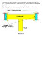
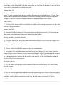
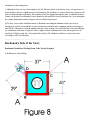
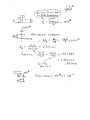
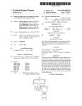
ENGINEERING ETHICS
THE CASE OF THE LAKEWOOD "HI-STAK"
Department of Philosophy and Department of Mechanical Engineering
Texas A&M University
Introduction
The Lakewood Company, a fairly large manufacturing firm, has designed, manufactured and sold hundreds of
self-contained storage/retrieval systems which are used for storing heavy parts such as dies, which must
intermittently be taken from storage and used elsewhere in the plant. The system consists of two large sets of
storage racks, facing each other, with an integral crane that runs between them on 2 bridge crane girders on the
top back edges of the storage racks (see Figure 1).
The crane has fork-lift appendages that can slip under a pallet on any of the several levels of the storage racks,
retrieve a pallet off the shelf, retract the pallet into the aisle, rotate it parallel to the aisle, and move it to the end of
the storage racks. The pallet is subsequently placed at the end of the aisle on the ground for pickup by a wheeled
fork lift and transportation to its final destination.
The Buchannan company, a large construction vehicle manufacturer, purchased one of these Lakewood "HiStak" units and was using it extensively until one of their employees, West Michaels, had an accident and was
seriously injured while operating the crane. (See the appended accident report written by Buchanan.)
According to eye witnesses, West had retrieved a 1,460 pound die from the top shelf, and was pulling it to the
end of the aisle. The load was well within the crane's advertised limit of 2,000 pounds. The next thing West
knew, as stated in the accident report, he was thrown about 20 feet. His next recollection was awakening in the
hospital bed.
The accident caused the crane wheels on the back side of the pallet to be pulled free of the lower flange of the
A588 steel W6X12 girder on the left side. (See Figures 2 and 3).
The sequence of events shown in the MPEG simulation gives an idea of how the
accident happened.
Same events, top view.
Accident Report
Interoffice Memorandum
Buchanan Dies, Inc.
Facility: EAST PEORIA
Date June 22, 1994
Department: Plant Engineering - KK- 1
Attention: Dick Berger
From: Ted Jackson
cc: T. K. Essington, KK-l
Ken Towles, HH Facilities Services
Dave Monroe, Purchasing, A1
Robert Hennelly, Meg., Tl
Subject: ACCIDENT INVESTIGATION - Building HH:20E
A. Accident description:
A Buchanan employee, West Michaels, was injured on May 23rd, 1994 while performing his duties as a FMS
operator on the HH Track Shoe line. He was using a Lakewood "Hi-stak" self-contained storage/retrieval
system to store fixtures and dies. The system consists of a top running crane supported by storage racks on each
side. The trolley/stacker unit fell to the floor throwing Mr. Michaels about 20 feet. The crane was loaded with a
pallet and die weighing a total of 1460 pounds which is well below the system rating of 2000 pounds.
B. Summary & Conclusions:
The employee was doing his job using the tools and procedures provided to him by Buchanan. Buchanan had
purchased the unit as a self-contained system from Lakewood, Inc. through their representative Fogerty Brothers
Company. The 2 bridge crane girders were obviously too weak to keep the trolley unit in its proper position
during normal loading. Our structural calculations, based on the known live and dead loads without adding
impact, show that the one girder was overloaded. The girder was not stable under load and deflected laterally
enough to allow the trolley wheels to slip off the girder flange. The crane girders must be reinforced for vertical
load. The lateral loading caused by the trolley wheel position on the crane girder bottom flange should be
reduced or the girder must also be reinforced for lateral stability. Safety lugs mounted on the trolley unit and over
the crane girders should also be installed. Lakewood will design the changes and obtain our agreement on the
design. Buchanan HH Facilities Services personnel will make the changes at the direction of Lakewood's
serviceman.
We will also work with Stans-Vixen to verify the safety of their similar type storage units.
C. Detailed investigation & findings:
The following is a complete history of all my contacts with Lakewood and others that I have received or made
since this accident occurred. I have also listed other activities completed during this time period.
Wednesday, May 23rd
1. On Wednesday, May 23, 1994 at 8:47 a.m. a Buchanan employee, West Michaels, was injured while using
an Lakewood "Hi-stak" storage/retrieval system. A copy of the accident report is enclosed.
2. 10 am - I went to HH20E to investigate the accident. The crane trolley had slipped out from between the two
crane girders and fell to the shop floor. The load was high above the floor and behind the south girder at time of
failure. The evidence at the accident scene indicated that two trolley wheels had slipped off the south girder first.
The weight of the load caused the trolley mast unit to pivot about the front girder. The mast swung up striking
Mr. Michaels and throwing him about 20 feet north. Fortunately, he was thrown clear of the falling equipment.
See also my notes on physical dimensions taken of crane unit, and photographs taken at the scene of the
accident.
3. 11:40 am - Dennis Pond reported that the die that fell actually weighed 1285 pounds.
4. 12:32 pm - Ron Fox left a message that the die pallet weighed 175 pounds. Therefore, actual total weight of
die and pallet of 1460 pounds is much less than the rated system load of 2000 pounds.
5. A drawing file search found 3 drawings on this "purchased finished" Lakewood system as follows:
PE15000-L8 Die Storage Loads Layout
PE15000-L12 Area Layout including Die Storage Area
PE15000-S26 Lakewood proposal drawing. FMA-22393
These drawings were used to install the storage system and do not include any details on the components of the
system.
6. 12:47 pm - Dennis Pond expressed a concern about the rack structure also moving when the stacker crane
travels.
7. 1:53 pm - At his request, I updated Larry Lindsey of Y3 Safety on the accident. He was interested in the
proper technical terminology for the crane storage system.
8. Purchasing notified Tom Damman at Fogerty Brothers Company of the accident. Fogerty sold Buchanan the
Lakewood system in 1986. It has been used successfully and without incident until now. Tom made
arrangements to get Lakewood people in as soon as possible. Dave Monroe, Tom Damman and I visited the
accident site in the afternoon.
9. 7 pm - I inspected 3 similar "Stans-Vixen" units in building KK. See enclosed data sheet for summary units at
buildings KK31B, KK37A and KK48A.
Thursday, May 24th
10. 7:57 am - Dave Monroe called to say Lakewood will be here today.
11. 9 am - Lakewood representatives Nick Magotta (District Sales Mar.) and C. R. (Dick) Johnston (Customer
Service Rep.) and Mark Witt from Fogerty Brothers visited the accident site with Dave Monroe and myself.
We met in a conference room and agreed to the following plan of action:
Lakewood will proceed to repair the trolley unit.
Lakewood will investigate installing safety lugs or beams on the trolley unit to prevent a similar accident in
the future.
Lakewood will check the need to reinforce or rework the bridge crane girders.
Lakewood to verify if this system was a standard unit or a specially designed unit for Buchanan's needs.
(Sue later found that this 8 foot 3 inch wide aisle unit was one of Lakewood's standard units.)
Lakewood to inform us of the timing (schedule) and who will do the actual repair work. Buchanan to write
a B94 account work order to accumulate our costs for possible back charging to Lakewood at a future
date. Lakewood said they were no longer in this storage unit business and had sold the division to MBT
Systems. They said it would take a few days to locate the original drawings for this system. We also
agreed that all contacts must be coordinated through Dave Monroe in Buchanan purchasing or his
designated person.
12. Phil Burroughs of HH provided a sketch of the trolley wheel dimensions. The critical distance from the small
guide roller to the edge of the trolley wheel tread on the crane girder is only 1 and 5/16 inches. The tread radius
reduces the wheel tread contact width to 1 and 5/32 inches. See the sketch enclosed.
13. Dave Monroe telephoned Gene Kent of Crank Midwest Co. to express our concern about the safety of
similar Stans-Vixen units he has sold to Buchanan. Dave and I wanted Gene to make arrangements with StansVixen people to visit our plant and discuss the safety of their product.
14. 1:20 pm - I expressed our concern about the safety of Stans-Vixen units to Vim Joliat, Technical Sales Mgr.
at Allentown, PA based our accident yesterday.
Friday, May 25th
15. 12:20 pm - Ken German called and I updated him on Lakewood's visit.
16. 2:10 pm - Ed Smith from General Business Services, Inc. in Springfield called to make an appointment to
see the accident site in HH. He said he represented Lakewood as a "claims adjustment" service. He also said he
was trying to reach Ken German to set up the visit. I told Ed I would forward his request to Ken German.
17. 2:32 pm - Left message for Ken German about Ed Smith's request to visit accident site on Tuesday May
29th.
Monday, May 28th - Memorial Day Holiday
Tuesday, May 29th
18. 10:30 am - Ed Smith here and visited accident site with Ken German after Ken received advice from Tom
Skowronski in Legal, G.O. to allow the visit. A set of 18 photographs were taken at the site and forwarded to
Ed Smith via Legal.
19. 10:40 am - Vim Joliat from Stans-Vixen called and set up a conference call with me and his people. He had
Jack Remington and Bill Deveny in the room with him. We discussed Buchanan's concern with their crane
system design based on the accident we had on May 23rd. They said there were many of these units in use
worldwide. They had experienced no similar failures with their cranes. We discussed their structural design of the
trolley and crane units and they could see no problem. They mentioned a maximum trolley wheel load of 3133
pounds on their 2000# rated load system. I expressed a concern about the torsion load on their MC 6x12 ship
channel girders due to the eccentric wheel loading condition. They tried to convince me that their system design
was good and I said we would probably be calling them again for more information.
20. 11:29 am - Called Stan Hufford and arranged meeting to get information on the Lakewood system from his
file on purchase of the system in 1986-87.
2:04 pm - Stan Hufford called and we set meeting for today. Met with Stan at his office and copied several
documents about the system purchase and obtained his copy of the 1985 Lakewood system catalog. This
system was ordered from Fogerty Brothers on 12-08-86 on P.O. PYXD93375 U.
22. 3:20 pm and 3:52 pm - Discussed the accident and progress with Lakewood, first with Ken German and
then with Dave Monroe.
Wednesday, MAY 30th
23. 9:53 am - Gene Kent of Crank Midwest Co. (Stans-Vixen rep.) called and left message he wanted to see
me today.
24. Gene Kent met with me and gave me a list of 38 Stans-Vixen storage units sold to Buchanan. These units
were sold to our East Peoria plant, York plant, Aurora plant, and Juliet plant. His list shows 29 units sold to East
Peoria plant. He also included two catalogs on the units.
Thursday, May 31st
25. I went to HH:20E and recorded additional dimensions needed to do structural calculations on the Lakewood
system. The rack system and aisle width were verified with catalog data as originally ordered. 3:22 pm - Dave
Monroe called to inform me that Dick Johnson at Lakewood was having problems locating the storage unit
drawings. He may have to travel to Michigan on Monday to find the drawings at MBT Systems.
Friday, June 1st
27. 12:35 pm - Dave Monroe called to say Jim McLeod would be my Purchasing contact next week since Dave
would be in Europe on business.
Saturday, June 2nd
28. I dropped off to Ken German at Y3 a list of items discussed with Lakewood at the 5-24-94 meeting and
other storage system information I had recently gathered from Stan Hufford.
Monday, June 4th ( I was sick & off work)
29. 12:59 pm - Angela Kemp from Public Affairs called and left message to set up a safety video taping of the
HH accident story for Friday, June 8th at 8 am.
Tuesday, June 5th
30. 7:09 am - Jim McLeod called for update on Lakewood communications.
31. I received by U.S. mail additional data from Gene Kent of Crank Midwest Co. on the Stans-Vixen StakSystem. The three pieces of literature covered 1) warranty information, 2) Stak-System installation & operation,
and 3) Duff-Norton hoist operating & maintenance instructions. 2:50 pm - Dick Johnson of Lakewood called to
say he has found the trolley drawings and they would be sent out today. He also verified that the crane girder
section is a W6x12 as we had suspected.
Wednesday, June 6th
33. 8:52 am - Jim McLeod called to say Dick Johnson of Lakewood would be here at 10:30 am to visit the
accident site again.
Friday, June 8th
34. 8:00 am - JMS did engineering calculations showing the original design of the Lakewood Hi-stack system to
be inadequate under the design loads. The major problem is the equivalent 813 pound lateral load on the W6x12
wide flange, which bends the section about its weak axis. The wide flange is overstressed by 3.29 to 1.
End of Document
Ethical Issues in This Case
1) Should Buchanan give approval to the modified Lakewood design?
Numerical Problems
Numerical Problem #1:
Using the AISC LRFD code specifications applicable to crane rails, determine the design loads to which the rails
could be subjected, and determine if the beam is acceptable by AISC standards. The beams were 12 foot long
W6x12 made of A588 steel, and you may make worst case assumptions about direction and location of loading.
You may also assume that the ends of the beams are pinned.
Numerical Problem #2:
Determine the required lateral deflection of the wide flange assuming that the operator was traveling as slowly as
would be required to just barely cause the wheels to slip off of the lower flange.
Numerical Problem #3:
Using energy methods, determine a lower bound on how fast the crane must have been moving to just barely
cause the wheels to slip off. Would you consider this design safe to use? Walk this speed. Would you consider
this design safe to use?
Numerical Problem #4:
Calculate the maximum possible lateral deflection of the wide flange assuming that the wheels did indeed slip off
of the lower flange, and that the operator was running with the crane, failing to stop before hitting the end stops.
Note that no permanent plastic deformation of the crane rails was noted after the accident.
Numerical Problem #5:
Using energy methods, determine an upper bound on how fast the crane might have been moving when the
wheels slipped off. Does this change your opinion of the safety of the design? Do you feel that it might have been
possible that the operator could have caused his own problems by moving too fast with the crane and running
into the stops?
Numerical Problem #6:
Shown in figure 3 is a set of calculations provided by Buchanan which they feel proves the original Lakewood
design to be inadequate. Do you agree with these calculations, and if not, in what respect?
Numerical Problem #7:
Against Buchanan stated safety procedures, and in direct violation of safety stickers on the crane and listed in the
user's manual, the load was transported fully raised, above the operator's head, rather than having been lowered
close to the floor immediately after removal from the shelf. Did this operator behavior contribute in any way to
the accident and/or to the employee's injuries? Note that the employee was not struck by the falling die, which
was on the other side of the crane when it fell. Rather he was involuntarily propelled by the crane.
Numerical (Design) Problem #8:
a) What mechanical measures might you add to the HI-Stak unit to prevent similar future accidents? Do you feel
that the added expense would be worth the added costs? Should Lakewood voluntarily track down and retrofit
the hundreds of existing cranes they have sold, realizing that this is the first accident noted since their introduction
in 1986?
(b) What electronic interlock controls might you add to the crane system and/or operating controls to prevent the
circumstances that contributed to the accident?
Numerical Problem #9:
How fast could a worker travel with the crane and hit the stops if beam safety hooks are used? Assume that both
beams will be pulled into complete plastic deformation for this problem. Would you consider this a safe speed?
Would you consider the design safe under these conditions?
Numerical (Design) Problem #10:
Redesign the wide flange such that there will be no overstress under normal loading, assuming that safety devices
have been installed to prevent lateral disengagement of the wheels under lateral impact loading.
Lakewood's Side of the Story
Against all safety precautions, Mr. Michaels was transporting the load at full height above the floor, thus directly
causing this accident. This is in direct violation of the safety regulations of Buchanan, as well as the safety stickers
prominently displayed on the crane, and in the user's manual. Further, Mr. Michaels took the required safety
classes in use of the equipment, where this requirement was emphasized. Loads are never to be transported high,
but rather must be lowered to the floor immediately after retrieval from the storage shelves. We contend that this
negligence was the full and complete cause of this accident, for the following reasons:
a) Carrying the load level with the upper support beams would directly transmit tremendous impact loads to the
support beams, should the operator negligently fail to stop the crane and crash it into the stops. Our tests show
that if the loads are transported close to the ground, the crane merely swings forward, reducing the impact
loading at the top of the crane to very low levels, greatly reducing the possibility that the wheels can disengage.
b) We admit that should someone crash the crane into the stops, they might actually cause the wheels to come
out of the tracks on the back side of the crane. However, should this happen with the load low, the load will
merely rotate the crane about 5 degrees, until the pallet is directly under the engaged wheels, or until the load
touches the concrete floor. In either case, the rotation of the crane is slight, and rather than propelling the
operator across the room, he will probably not even be touched by the crane.
However, should the wheels disengage with the load in high position, the load will rotate the crane 40 to 50
degrees before falling off of the forks. Just like a golf ball, the operator's negligence might cause him to be struck
and injured by the rotating crane.
c) Although we have no way of knowing how fast Mr. Michaels ran the crane into the stops, it is apparent to us
that it must have been at a significant speed. Statements by Mr. Michaels' co-workers that he has caused several
other accidents through carelessness, and testimony of his "hot-dogging" through the plant, confirm this behavior.
Further, the fact that several hundred cranes identical to this model have been in operation for 8 years throughout
the country demonstrates that the design is safe and reliable if not abused.
d) We have reviewed the calculations made by Buchanan concerning the minimum velocity necessary to
disengage the wheels, and would like to point out that this would indeed be a minimum, and has no bearing on
how fast Mr. Michaels was actually running at the time of the accident. We would also like to note that although
our calculations at this time do appear to show a slight overload condition for the crane when operated at its
rated load of 2000 pounds, the 1460 pound load carried by Mr. Michaels would not overstress the crane,
according to AISC specifications.
Buchanan's Side of the Story
Buchanan Calculations Showing Beam To Be Poorly Designed
Calculations for wheel loading:
The maximum loading on the W6x12 beam is realized when the pallet and die are rotated directly over one of the
carriage wheels, as shown above.
The die and pallet live load rating is 2000 pounds, and can be up to 29 inches from the center of rotation of the
crane. The dead load of the crane itself is 1875 pounds, and is located at the point of rotation of the crane. Using
AISC-LRFD design procedures, the factored live load, including a 10% allowance for impact (Section A-4.1
and A-4.2) is
Plive = 2000# * 1.6 * 1.1 = 3520#
The factored dead load = Pdead = 1875# * 1.2 = 2250# (no impact needed)
First, assume that the live die load is applied at the center of rotation. Then the live load on each wheel due to
central die load = 3520# / 4 wheels = 880#
Since the die load is actually off center, it causes a moment about line A-A:
Moment about line A-A = 3520# * 29" = 102.080 in lbs, which must be resisted by wheels b and d. Since these
wheels are on the hypotenuse of a triangle, they are [(41/2)^2+(37/2)^2]^0.5 = 26.6 inches from the center of
the crane.
Summing moments about wheel line A-A, to determine load on wheel "b":
Sum moments about line A-A = 0 = 3520# * 29" - wheel b load * 27.6" - wheel d load * 27.6"
Assuming wheels b and d have the same load due to symmetry, Live load on wheel b = 1850#. The load
Calculations for equivalent beam loading:
P2 is the maximum calculated wheel load, which is 1" off center. PL is the equivalent lateral load which gives the
same torsional twist to the beam as did P2, when P2 is moved to a direct shear position. This lateral load causes
significant bending about the weak axis of the beam, as shown in the calculations below.