1
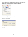
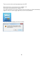
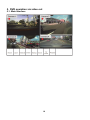
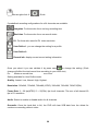
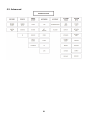
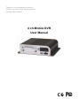
Thank you for purchasing our product. Please read instructions before operation. Change without Notice 4 ch Mobile DVR User Manual Safety Precautions CAUTION RISK OF ELECTRIC SHOCK CAUTION : To reduce the risk of electric shock, do not expose this apparatus to rain or moisture. Only operate this apparatus from the type of power source indicated on the label. The company shall not be liable for any damages arising out of any improper use, Even if we have been advised of the possibility of such damages. Graphic Symbol Explanation The lightning flash with arrowhead symbol, within an equilateral triangle, is intended to alert the user of the presence of insulated dangerous voltage within the product’s enclosure that may be sufficient magnitude to constitute risk of electrical shock to persons. This exclamation point within an equilateral triangle is intended to alert the user of the presence of important operating and maintenance (servicing) instructions in the literature accompanying the appliance. All lead-free products offered by the company comply with the requirements of the European law on the Restriction of Hazardous Substances (RoHS) directive, which means our manufacture processes and products are strictly “lead-free” and without the hazardous substances cited in the directive. The crossed-out wheeled bin mark symbolizes that within the European Union the product must be collected separately at the product end-of-life. This applies to your product and any peripherals marked with this symbol. Do not dispose of these products as unsorted municipal waste. Contact your local dealer for procedures for recycling this equipment. WARNING: TO PREVENT FIRE OR SHOCK HAZARD, DO NOT EXPOSE UNITS NOT SPECIFICALLY DESIGNED FOR OUTDOOR USE TO RAIN OR MOISTURE. Attention: installation should be performed by qualified service personnel only in accordance with the National Electrical Code or applicable local codes. FCC STATEMENT WARNING This device complies with Part 15 FCC Rules. Operation is subject to the following two conditions: (1) This device may not cause harmful interference. (2) This device must accept any interference received including interference that may cause undesired operation." WARNING This Equipment has been tested and found to comply with the limits for a Class B digital device, pursuant to Part 15 of the FCC rules. These limits are designed to provide reasonable protection against harmful interference in a residential installation. This equipment generates uses and can radiate radio frequency energy and, if not installed and used in accordance with the instructions, may cause harmful interference to radio communications. However, there is no guarantee that interference will not occur in a particular installation. If this equipment does cause harmful interference to radio or television reception, which can be determined by turning the equipment off and on, the user is encouraged to try to correct the interference by one or more of the following measures: - Reorient or relocate the receiving antenna. - Increase the separation between the equipment and receiver. - Connect the equipment into an outlet on a circuit different from that to which the receiver is connected. - Consult the dealer or an experienced radio/TV technician for help. You are cautioned that changes or modifications not expressly approved by the party responsible for compliance could void your authority to operate the equipment. TYPE A/TYPE B/TYPE C ..................................................................................................... 錯誤! 尚未定義書籤。 User Manual ...........................................................................................................................................................1 1. Package Contents ...........................................................................................................................................1 2. Product Overview ..........................................................................................................................................3 3. Physical Connection .......................................................................................................................................7 3.1. Hard disk installation ....................................................................................................................7 3.2. Sim card installation ...................................................................................................................10 4. Setup ............................................................................................................................................................14 5. DVR operation via video out ........................................................................................................................19 6. 7. 5.1. Main Interface ............................................................................................................................19 5.2. Advanced ....................................................................................................................................21 5.2.1. Record Setup ..............................................................................................................................22 5.2.2. Device .........................................................................................................................................23 5.2.3. Event Setup .................................................................................................................................25 5.2.4. Network Setup ............................................................................................................................29 5.2.5. Account .......................................................................................................................................32 5.2.6. System tools ...............................................................................................................................32 5.2.7. System Info .................................................................................................................................36 5.3. Search ......................................................................................................................................... 37 5.4. Backup ........................................................................................................................................ 37 5.5. Sound ..........................................................................................................................................38 5.6. Display ........................................................................................................................................38 5.7. PTZ ..............................................................................................................................................38 5.8. Playback ......................................................................................................................................39 DVR operation via browser ..........................................................................................................................40 6.1. Video ..........................................................................................................................................41 6.2. Record .........................................................................................................................................43 6.3. Camera setting............................................................................................................................45 6.4. Event ...........................................................................................................................................46 6.5. Network ......................................................................................................................................50 Configuration ...............................................................................................................................................54 7.1. 7.1.1. Information .................................................................................................................................54 System ........................................................................................................................................54 7.1.2. 7.2. 8. Display ........................................................................................................................................54 Account .......................................................................................................................................55 7.2.1. Date and time .............................................................................................................................56 7.2.2. Car information ..........................................................................................................................56 7.2.3. Format ........................................................................................................................................ 57 7.2.4. Log ..............................................................................................................................................58 Vehicle Management Software (VMS) works only for TYPE A ..................................................................60 8.1. Server software installation ........................................................................................................61 8.2. Client software installation .........................................................................................................62 8.3. Operation....................................................................................................................................63 8.4. Tool bar description ....................................................................................................................67 8.5. Program interface .......................................................................................................................77 8.5.1. Open AVI .....................................................................................................................................78 8.5.2. Open HDD ...................................................................................................................................79 8.5.3. Control bar description ...............................................................................................................80 8.5.4. Snapshot .....................................................................................................................................81 8.5.5. Setting.........................................................................................................................................82 1. Package Contents Description Picture Type A TYPE B TYPE C V V V I/O cable V V - 3G antenna (Female/ 2.5 db) V - - G-Mouse (Male/5m/-15 9dbm) V V V Wifi antenna (Female/ 2 db) V - - Remote Controller + battery V V V Screw x 5 V V V Nylon cable tie x 10 V V V Power cable (6 pin/6m) + 5A fuse X 2 1 Hard disk rack locker key Video cable (6 pin/minidin type/ female-male/ 6m) Camera CC2 042 x 4 USB Mouse External indicator + bracket + cable 2 V V V optional optional optional optional optional optional optional optional optional optional optional optional 2. Product Overview TYPE A/TYPE B/TYPE C Front Panel TYPE A Back Panel TYPE B Back Panel TYPE C Back Panel Cable pin definition 3 I/O cable pin definition 4 Video cable Pin number 1 2 3 4 5 6 Mini din type Description Power Audio Not used Not used Ground Video 5 The function button of this IR remote controller as below Power:Turn on/off DVR Info:Show DVR information Backup:Backup the recorded data to other device REC:Panic record Audio:Audio ON / Mute PTZ:Control Pan/Tilt/Zoom camera. Quad, 4CH display mode ◀I:Preview frame ||/▶:Play or Pause during playback I▶:Next frame ◀◀:Fast Reverse play,2x,4x,8x speed ■:Stop playback and go to Live mode ▶▶:Fast Forward play,2x,4x,8x speed Direction (▲,▼,◀,▶) Move cursor or control PTZ camera ENTER Select sub item in system setup mode Lock : lock the DVR system need a pa ssword to unlock it SEARCH :Search recorded video MENU : Go to ‘MENU’ mode to setup the syste m ESC:Exit the dialog window 6 3. Physical Connection 3.1. Hard disk installation Remove the mobile DVR hard cover and insert the locker key in the front of the device, To unlock please turn counter clock wise 90°, To lock it please turns clock wise 90° 7 Then turn counter clock wise the two screw Pull the rack out in order to install your hard disk, note that only 2.5 inch hard disk can be installed Screw the hard disk as shown on the below drawing 8 Then connect the SATA and power cable on the back of the hard disk it should look like this : After you installed the hard disk put back the rack into the mobile DVR and tighten the two front screws and use the key to lock the rack. If the lock is not correctly done, the system won’t be able to boot and the power led will flash 9 3.2. Sim card installation When you purchase your sim card to your telecom provider, please make sure that it meets one of the following standard in order to work : GSM 850 900 1800 1900 WCDMA 850 1900 2100 Pull the sim card socket Insert the sim card with its gold contact facing down and the notched corner oriented to the upper right of the slot as shown Then put back the lid to the slot and push to lock it 10 At final your mobile DVR should look like this 11 Power Setup Cable type Meaning Ground Power + ACC power Connect to acc of your car - + CAR BATTERY DVR For your information ground and power + cable are protected with a 5A fuse. Note that, do not pull the power connector when the DVR is recording to avoid the hard drive be damaged. First unplug all cameras, wait that yellow led turn off then unplug the power 12 Icon description table Icon Description Color Always ON Always OFF Flashing Vloss, no hdd, no recording, GPS capturefailed System boot upfailed WARNING Red x x RECORD Yellow x No recording Recording x x Warming the system up to 0°C because environment temperature under 5° C HEATER Blue POWER Green System ready ACC turned off ACC on system not yet ready GPS Green Localization success (more than 4 satellite s 4 included G-mouse not connected, or signal strength too weak Localization in process,1 to 3 satellites detected , gps data not available WIFI Green Connected to AP Not connected X WWAN Green Connected Not connected X NETWORK Green Connected Not connected X 13 4. Setup In order to access to the 4 channel mobile DVR with a notebook, you need to have RJ45 cross cable Link the notebook to the DVR with the LAN cable Under windows 7 On the desktop bottom right, right click mouse on network icon then select open network and sharing center Then on the left select Change adapter settings Choose your lan wired connection then mouse right click and select properties Then click on Internet Protocol IPV4 and click properties 14 Assign an IP address to your notebook as the DVR default IP is 192.168.1.99 15 Valid by pressing ok Internet Explorer setting Our device supports Internet Explorer 7, 8, 9 32 bits only The default IP address of the mobile DVR is 192.168.1.99 In order to install the active X you need to change your Internet Explorer settings Open Internet Explorer, Click the Tools button, and then click Internet Options. Click the Security tab, and then click a security zone Trusted sites. Click Sites. 16 The DVR IP should be shown in the Add this website to the zone field. Please make sure that the below option ‘require server verification’ is disabled Click Add and close. Then turn the Security level to Low and press apply Return to Internet Explorer main page You will have a pop up message Press Install 17 The icon must be in blue color then please login in the DVR Default administrator username/password is “admin”/ “1111” Default guest username/password is “guest”/ “1111” If you don’t operate the car dvr after a period of time (30 minutes) you will be automatically logged out, then you need to loggin again with your account and password A pop up message will display, press Yes to continue 18 5. DVR operation via video out 5.1. Main Interface 19 Mouse right click Quick 5 predefined recording configurations for all 4 channels are available. Longtime: For those who focus on long recording time Real time: For those who focus on smooth video D1: For those who want full D1 video resolution User Define 1: you can change the setting for a profile User Define 2: Record info: display current record setting information Once you select it you can validate it by press save or change the setting. (Each change will affect the total record time according to your HDD size) Ex: Minimum record time xxxx Hour Setting available for User Define mode: Quality: Lowest, Low, Normal, High, Highest. Resolution: 320x240, 720x240, 720x480 (NTSC)/ 320x288, 720x288, 720x576(PAL) Frame Rate: 3 ~ 30 fps(NTSC)/ 3 ~ 25(PAL) fps for all channels. The sum of all channel 60 fps in D1 resolution. Audio: Select to enable or disable audio for all channels Overwrite: Once the hard disk is full, the DVR will clear 2GB data from the oldest for continuous recording without notice 20 5.2. Advanced 21 5.2.1. Record Setup 5.2.1.1. Record Setup You can set up recording each channel individually Channel: select the channel you want to set up 1 ~ 4 Start Record: enable or disable manual recording Frame Rate: 3 ~ 30 fps Quality: Lowest, Low, Normal, High, Highest. Resolution: 320x240, 720x240, 720x480 or 320x288, 720x288, 720x576 for PAL system Prerecord: select to enable or disable the pre alarm record. You can define pre alarm record time from 1 to 10 seconds Audio: select to enable or disable audio Post Record: select enable or disable the post alarm record, user can define post alarm record time from 1 to 30 seconds Data Retention: define number of day of recorded data to keep in the hard disk, values vary from 0 to 30 days Overwrite: ‘On’ means DVR will erase old data and record new data, ‘OFF’ means DVR will not overwriting the hard disk and stop recording when the disk is full 5.2.1.2. Ignition off Postpone time: user can define after the ignition off how long it will keep recording. The values available are 30 sec, 5, 10, 15, 20, 25, 30, 35, 40, 45, 50, 55, 60 min Normal, Motion, Sensor, Gsensor 22 5.2.2. Device 5.2.2.1. 5.2.2.1.1. Camera Setup PTZ SETUP PTZ protocol : pelco p or pelco d PTZ ID: 1 ~ 255 PTZ baud rate: 110, 300, 1200, 2400, 4800, 9600, 19200, 38400, 57600, 115200 5.2.2.1.2. CAMERA SETUP Select the camera you want to setup by clicking on the left of the camera number Camera Title: you can rename the camera at your convenience maximum 20 characters Color Setup Brightness value 0 ~ 10 Contrast value 0 ~ 10 Saturation value 0 ~ 10 Hue value 0 ~ 10 Mask: You can define an area to cover in the camera for example bank atm, entrance access control keypad, 23 5.2.2.2. Storage This section provides information regarding the storage device installed in your combo DVR such as brand, series number, size and enables user to format it FORMAT PROCEDURE Press format with the arrow A message will display Are you sure to format?’ Press Yes to start hard disk format once finished another message will display Format Success!! Press ok to return 5.2.2.3. IR setting In order to control different DVR with one unique controller, or to avoid two DVR behave at the same time, it’s necessary to setup id IR ID values available: 1-1 1-16, 2-1 2-16, 3-1 3-16, 4-1 4-16 24 5.2.3. Event Setup Mouse right click Advanced Event Setup Please select the camera to setup by pressing the up or down arrow Three events can be setup: VIDEO LOSS, MOTION and SENSOR 5.2.3.1. Video Loss Enable: ON/OFF Camera: select the canal to setup or all camera Dwell time: define the length of the buzzer after each video loss 0 ~ 10 seconds Email: can send an email to predefined address in case of the event Alarm out: in case of video loss, DVR will send a signal via alarm out like a buzzer or flashing red light Press save to validate your choice or to exit 25 5.2.3.2. Motion Camera: select the canal to setup 1 4 or all camera Enable: ON/OFF Dwell time: define the length of the buzzer after each motion detection 0 ~ 9 seconds Email: can send an email to predefined address in case of the event Alarm out: in case of motion detection, DVR will send a signal via alarm out like a buzzer or flashing red light Event Record: ON motion record enable, OFF motion record disable Event popup: ON/OFF Sensitivity: 1 (lowest sensitivity) ~ 5 (highest sensitivity) Press save to validate your choice or to exit Area Setup You can use the mouse to select the area, then double right click on the mouse to display the options. SELECT ALL: all screens will be under detection CLEAN ALL: all screen will not be under detection SAVE: validate your selection EXIT: to leave the area setup menu Transparent blocks represent the area that is not being detected while the green blocks are the area under detection. 26 5.2.3.3. Sensor (for TYPE A and TYPE B) Sensor: 1 to 8 Camera: select the canal to setup 1 4 or all camera Enable: setup the status of the sensor OFF / NC/ NO Dwell time: define the length of the buzzer after each sensor trigger 0 ~ 9 seconds Alarm out: in case of sensor trigger, DVR will send a signal via alarm out like a buzzer or flashing red light Event Record: ON sensor trigger record enabled, OFF sensor trigger record disabled Event popup: ON/OFF 5.2.3.4. Speed Event Enable: ON/OFF Unit: you can choose between KM/H or MPH Type: High speed / Low speed Enable: ON/OFF Threshold: 1 ~ 300 Dwell time: define the length of the buzzer after each motion detection 0 ~ 9 seconds Email: can send an email to predefined address in case of the event Alarm out: in case of motion detection, DVR will send a signal via alarm out like a buzzer or flashing red light 27 5.2.3.5. G Sensor Enable: ON/OFF Threshold : OFF ~ 5g G value Max variation : OFF ~ 5g Dwell time: define the length of the buzzer after each motion detection 0 ~ 9 seconds Email: can send an email to predefined address in case of the event Alarm out: in case of motion detection, DVR will send a signal via alarm out like a buzzer or flashing red light Event Record: choose the camera to record 28 5.2.4. Network Setup 5.2.4.1. Lan 3G Quality : User can define quality of video transmitted over 3G network (Lowest, Low, Normal, High, Highest.) Host Setting: user can choose between STATIC IP, DHCP and OFF status For static IP you need to key manually the IP, GATEWAY and NETMASK. For DHCP, the DVR will retrieve the information from the network 5.2.4.2. Center IP: Net Service CMS server IP address. Center Port: default is 8787 but can be changed according to customer need Http Port: default is 80 but can be changed according to customer need Streaming Port: default is 554 but can be changed according to customer need Messager Port: default is 1999 but can be changed according to customer need DNS: if the user specifies a dns, it will help the cms to find more fastly the ip of the dvr using 3g connection Warning: make sure that these port are open in your router if you use a lan network 29 5.2.4.3. DDNS Enable DDNS: ON/OFF Host Name: your ddns host name. Service: now support DynDNS Account: ddns service account. Password: ddns service password. 5.2.4.4. E-Mail SMTP Server: E-mail service mail server. Port: E-mail service port. SSL: ON/OFF Sender: sender mail Recipient: recipient mail Enable SMTP Auth.(authentication): some mail server need user authentication. Account: mail service account. Password: mail service password. E-mail test: Due to the authorization problem, some mail server will not work properly. Please click the “E-mail test " button to test your mail server. If you don't receive the email, please contact with your MIS department or change another mail server and try again. 30 5.2.4.5. 3G Network (only for TYPE A) Enable: ON/OFF Access Point Name (APN): default is Internet. Access Number: default is *99# 5.2.4.6. WIFI (only for TYPE A) Enable: ON/OFF SSID: input your WIFI AP name. Key: input your WIFI AP connect key. 31 5.2.5. Account Enable or disable user authentication when DVR boot up User can modify password and add information such as Mobile phone or Email User can setup administrator and guest password 5.2.6. 5.2.6.1. System tools Time Setup Date: Year- Month-Day Time: Hour-Minute-Second Display format available: Month/Day/Year, Day/Month/Year, Year/Month/Day Time format: 12 hour or 24 hour Daylight Saving: enable or disable, after user selects the time zone, if daylight saving is enable, the DVR will automatically adjust the time 32 5.2.6.2. Display Select language CVBS Height adjustment: 1 ~ 9 CVBS Width adjustment: 1 ~ 9 You can enable or disable the following function by click or unclick them System time Channel title Recording Motion Alarm Network 33 5.2.6.3. Upgrade After you received the new firmware which name is image.bin, just copy it to a usb solid disk formatted in FAT32, insert in the usb port and click upgrade you will this following message Message Description waiting Are you sure to upgrade ? Starts the upgrade process The usb key is being initialized, the yes/n o will appear after few second If press yes it will look for the file in th e usb key search file upgrade system please wait 1/4 (3/3) Upgrade complete. the system will t reboo Press ok to reboot the device 5.2.6.4. Car Info Setup User can add car info such as: device number, company name, driver name, car number 5.2.6.5. Import setting User can import or restore setting Message waiting Are you sure to import config Import complete! The system will reboot! Description Starts the process The usb key is being initialized, the yes/n o will appear after few second Press ok to reboot the device 34 5.2.6.6. Export Setting User can export or backup setting Message Description waiting Are you sure to export config ? Starts the process The usb key is being initialized, the yes/n o will appear after few second Press ok to leave the export mode Export finish ! Notice: The export file name is Config, you can rename it for archive purpose but you must rename it as Config if you want to use it to restore setting in your combo DVR 5.2.6.7. Default This enables user to reset setting to default. Message Description waiting Are you sure to reset default? Reset Default Finish! Starts the process Yes to validate, No to cancel Press ok to reboot the system 35 5.2.7. System Info 5.2.7.1. System info : Version of the firmware, Mcu version, sensor status 5.2.7.2. Network Info: DVR’s IP address, Mac address, netmask, gateway 5.2.7.3. Storage info: status mention if the hard disk is correctly working, its model name and storage utilization 5.2.7.4. Car info: Device number, Company name, Driver name, Car Number 5.2.7.5. GPS info: Time, Longitude, Latitude, Speed, Height, Direction 5.2.7.6. 3G info: Enable, signal, IP address, Net mask, Gateway 5.2.7.7. Wifi info: Enable, ssid, IP address, Net mask, Mac address, Gateway 36 5.3. Search Mouse right click Search Backup User can make a backup of specific period on any usb device such usb key, external usb hdd Time Search Key in specific time to playback the data, select the camera and click go search Log List Select the channel Define start and end time. Type available: system, motion, sensor, video loss, network remote access And click on Search it will display the results, and then select the event to play it back Net Service User can search received message from the central by date 5.4. Backup Mouse right click Backup Insert your usb solid disk and Select the channel you want to backup, define the time period and after the osd display your usb key free space memory, press GO BACKUP ! 37 5.5. Sound You can adjust the sound volume with or from 1 to 15 Select the channel you want to listen by selecting the channel or press mute disable sound 5.6. Display User can choose between quad display or car display 5.7. PTZ User can control the ptz during live display 38 to 5.8. Playback Mouse right click Playback User can playback last recorded file Fast Rewind Pause Play Fast Forward Slow forward: it will forward frame by frame Stop and return to main display 39 6. DVR operation via browser Live preview After you log in, you will access to live picture , there are 5 areas: 1 is all the function of the DVR which will be explain later in this guide 2 is the main display of the camera, to see a camera in full screen, just double click on it. To return to quad mode, please go to VIDEO/LIVE 3 is the log out function and language setting, you can switch between English and Chinese 4 is the information regarding the system (firmware, plugin) and regarding the car (serial number, company, driver name, licence plate number), and also control PTZ 5 is audio on/off 40 OSD operation 6.1. Video Live please check page 11 for more information Playback After you make sure that you have enabled video recording, you can playback a video. Select the date on the calendar Then select the time you want to watch Check on below line if it is the period you need If data are available a will appear, then press PLAYBACK, 41 if you press BACKUP then you have the specify the period then press START BACKUP you will have to specify the folder destination The backup process in % will appear in each channel When backup is finished, a confirmation message will display. Then press Live display to return to normal operation 42 6.2. Record User can choose to record one specific channel or all channel. User can enable or disable record. Total framerate available for CIF and half D1 is 120fps and for D1 60FPS If you have 4 cameras connected you can record at D1 resolution with 15 FPS per channel If you have 2 cameras connected you can record at D1 resolution real time 30 FPS per channel Quality level: you can select between low, normal and highest quality Enable or disable audio recording on all channel 43 General configuration Prerecord 0~10 sec Post record 0~30 sec Data Retention days 0~30 days Enable or disable overwriting on hard disk Ignition off: After you switch off the power, the user can setup ignition off time Record mode: you can select normal, motion, sensor and/or G-sensor record mode during after ignition off period. If the ignition off period is ended and that suddenly the car is subject to a move, the G sensor will be trigger and will activate the record. 44 6.3. Camera setting User can change camera title User can adjust camera brightness, contrast, saturation and Hue. Press apply to validate your choice PTZ setup: in order to control the PTZ, user has to setup correct protocol, ID and baud rate 45 6.4. Event 6.4.1. VLOSS Select the channel you want to display video loss message. Dwell time: 0 to 9 seconds Email: disable or enable Alarm out: if user wants send alarm out when video loss, click on the 1 so it has a click 6.4.2. Motion detection 46 User can setup motion detection one by one or all at the same time To select a cell: Mouse Left Click, / To deselect a cell: Mouse Right Click, To select or deselect a block: Press Ctrl + Mouse Click Blue area means selected /No color area means not selected User can setup which camera to record in case of motion detection Dwell time: 0 to 9 seconds Email: disable or enable Alarm out: if user wants send alarm out when motion detection, click on the 1 so it has a click Popup: displays a selected camera when motion detection occurs Sensitivity: 1 to 5 Press apply to validate your choice 6.4.3. Sensor (only for TYPE A and TYPE B) Sensor: 1 to 8 Enable: setup the status of the sensor OFF / NC/ NO Record CH: select which camera to record in case of sensor trigger Dwell time: define the length of the buzzer after each sensor trigger 0 ~ 9 seconds Alarm out: in case of sensor trigger, DVR will send a signal via alarm out like a buzzer or flashing red light Event popup: ON/OFF 47 6.4.4. G sensor Enable: ON/OFF Threshold: OFF ~ 5g G value Max variation: OFF ~ 5g Dwell time: define the length of the buzzer after each motion detection 0 ~ 9 seconds Email: can send an email to predefined address in case of the event Alarm out: in case of Gsensor detects a variation, DVR will send a signal via alarm out like a buzzer or flashing red light 48 6.4.5. Speed event This page let user to enable or disable the speed event detection Unit can be kilometer per hour kph or mile per hour mph User can enable or disable high speed detection, specify the highest speed threshold, its dwell time from 0 to 9 seconds, if send email or not and if enable the alarm out or not Same setting applies for low speed detection 49 6.5. Network 6.5.1. Network Settings This side enables user to setup network in order to remotely connect to it for example with a notebook for maintenance. If the network has a DHCP server, you can enable this function. Please make sure that gateway and subnet mask are the same on both side. 50 6.5.2. Net Service If your network has a router, please make sure to open these ports in order to enable smooth access to the dvr via browser or cms software. All these port can be customized according to your needs 6.5.3. DDNS service 51 Our mobile dvr supports DYNDNS service, user needs to apply for a hostname and have its own username and password registered at DYNDNS website 6.5.4. Email Smtp server: we recommend to use gmail Port: check with port your smtp server is using SSL: enable or disable according to your smtp server Sender: key in the email of the sender Recipient: key in the email of the person who will receive notification in case of event. SMTP authentication: enable or disable according to your smtp server if it’s enable user need to provide the mail account and password 52 6.5.5. Mobile network setting Here you can enable or disable 3G. Provide information of how to connect to the 3G network (please check your operator for dial up procedure) 6.5.6. WIFI setting Here you can enable or disable the wifi 53 7. Configuration 7.1. Information This section shows three type of information: Network such IP, http port, streaming port, MAC adress and gateway Wireless network such as connection type, IP and gateway Hard disk such brand size and occupation ration 7.1.1. System Network: displays current network setting and Mac address HDD: displays hard disk brand, model number, size and occupation percentage 7.1.2. Display User can choose between English and Traditionnal chinese User can select which items to display 54 7.2. Account Two level of user can be define and unlimited account can be created Guest can only see live picture Administrator as full authority on the device Cellphone and Email are just for reference and optional 55 7.2.1. Date and time Select your prefered date format and hour format here Enable or disable daylight saving, according to the time zone, it will automatically turns it on and off at the right time Here you can manually setup your device time or synchronize with your computer time 7.2.2. Car information Modify Serial number, Company name, Driver name and License number 56 7.2.3. Format User must format the hard disk before start recording Factory reset Once press this option a warning message will appear asking you if you want to reset, press YES to apply Press ok 57 7.2.4. Log For troubleshooting purpose, you can browse the log Select the starting and ending time, the channel concerned and use our 4 filters to reduce the number of event then press SEARCH. If you don’t select channel, it will display system event. 58 If you want to backup the log, press BACKUP, Then press download it will export all the events in one csv file Choose Save Then open the file with Microsoft Excel or any program suppoting csv file 59 8. Vehicle Management Software (VMS) works only for TYPE A Our VMS is composed : A client called MR VMS A pc viewer called MR PLAYER, A server software Mobile DVR send information to server via 3G network and any client can connect to server System architecture 60 8.1. Server software installation Server main purpose is to receive data from each mobile dvr, so user needs to tell to the dvr the server IP, open internet explorer and key in the dvr IP, then go to Network then Port 61 8.2. Client software installation First install Register server software located in the cd on your computer and follow instructions Then install the MRVMS software and follow instructions 62 8.3. Operation Server side: launch the application named register-server Default account and password are admin / 1111 63 Then you will access to a page showing device connection status At this page you can see each device serial number, Car ID, IP address, Update time and Status Export button enables user to repatriate all car information into a text file. Clear button enables clear the current list, the server will then updates automatically the mobile dvr that can be linked If the dvr is in grey color it means that it’s offline 64 Click on the second tab will let you access to account management page There are 3 level of account, Administrator, Operator and Guest each can be customized on the right side. This concerns loggin from cms client, Click on the third tab to access to the language display setting you can choose between English and Chinese Server setting: default port is 8787 , you need to double check on the mobile dvr that the port is the same otherwise the server wont be able to see the device 65 Start / Stop the service: the default setting is set on enabled but you can manually stop the server Client side: launch the application called HS VMS Default account and password are admin / 1111 Specify the server IP, Specify the server streaming port Choose the program language interface between English and Chinese 66 8.4. Tool bar description 8.4.1. Full Screen Displays the video in full screen on your monitor, to return to normal mode press ESC button on your keyboard 8.4.2. Video download Download recorded data from the dvr remotely, you can choose between, 1, 5, 10, 30, 60 minutes or all the date (it may affect the bandwidth and slow the connection) 67 8.4.3. Remote control Remote functions Two way audio Maintain speak button to talk with your interlocutor or to the driver. If you select recording, the conversation will be recorded in your computer 68 Text Message From the vms you can send a message to the driver to inform him of any important event or information, it will be display on the main monitor of the mobile dvr I/O control As the mobile dvr has an alarm output, user can give description of what kind of device is connected to it in case there is alarm out triggered 69 8.4.4. Remote setting let you remotely setup mobile dvr features all the functions are the same of the mobile dvr itself , to be able to access to the setting, the dvr must be connected. 8.4.5. VMS option Let you setup the snapshot path folder, (1/4/9/16/36), and also event log number live record path folder, split screen mode 70 8.4.6. Vehicle display Display or hide the vehicle list 4 type of display are available select the one according to your preference Car list: the program will show connected device with additional information, you can create or delete group for better management and pull one device to a group 71 Before to see live picture, you need to create a group. Click on right click on the mouse to display the functions Add car: choose the car you want to add by selecting them Then valid by pressing OK 72 , a car icon will appear, Here you can see live picture with gps information 73 This section allows you to control the ptz camera and adjust the camera quality 74 This figure show the g-sensor information This figure shows the real time speed of the car This section shows real time information such as event, vloss, relay out or motion detection 75 MR player application operation Default id/password is admin/1111 At this stage you can select between English or Chinese interface 76 8.5. Program interface 1 is showing the position of the car according to Google map database (or soso map for China) 2 is showing Gsensor information and current speed 3 is displaying video by date 4 is displaying video and let user to control playback 77 There are two way to open a file: 8.5.1. Open AVI To open a file press the first icon and find the folder you store the avi file You will be able see the recorded files displayed by date To play a file just double click on the date then a specific time 78 8.5.2. Open HDD After you select the hard disk you will see this display you can export the video into avi file by pressing the third icon 79 8.5.3. Control bar description Icon Description Open a avi file in a folder Open hard disk containing the video Convert a period from the hard disk into AVI format Stop the playback Playback Pause Fast Forward Playback previous file Playback next file Take snapshot of current video System setting 80 8.5.4. Snapshot If you press the snapshot icon , a window will pop out You can save manually or auto save the picture You can adjust print setting by pressing SETUP button, another window will come out You can add in your picture print license number, plate number, date and time, and also description (by adding text) If you press PRINT button, the computer will send the picture to your connected printer. 81 8.5.5. Setting Here user can select GPS display unit and also which map use If you are in China, please select soso map In this section you can manage your different account, by changing administrator password or add new account. There are no limits of number of account You can also delete user. 82