1
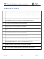
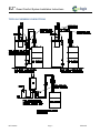
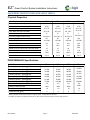
45 Cowansview Road Cambridge, Ontario, N1R 7L2 Phone: 855-658-4330 Fax: 855-658-9384 www.ecologix.ca [email protected] Owner’s Manual & Installation Instructions Ecologix EZ Zoned Comfort Distribution system ECOLOGIX HEATING TECHNOLOGIES INC. 45 Cowansview Road. Cambridge, Ontario N1R 7L2 Phone: 519-658-4330 Fax: 519-658-9384 [email protected] www.ecologix.ca Copyright (C) 2014 Ecologix Heating Technologies Inc. All Rights Reserved. This manual may not be reproduced in whole or part by any means without prior written consent from Ecologix Heating Technologies Inc. Ecologix and the Ecologix logo are Trademarks of Ecologix Heating Technologies Inc. EZ TM Zoned Comfort System Installation Instructions Table of Contents CHECKLIST FOR THE INSTALLER............................................................................................................. 4 TYPICAL PLUMBING CONNECTIONS........................................................................................................ 5 EQUIPMENT SPECIFICATIONS AND SIZING TABLES ............................................................................ 6 INTRODUCTION ............................................................................................................................................. 7 HOW IT WORKS ............................................................................................................................................ 7 Zone One ...................................................................................................................................................................... 7 Off ................................................................................................................................................................................ 7 Heating ........................................................................................................................................................................ 7 Cooling ........................................................................................................................................................................ 7 Continuous Fan ............................................................................................................................................................ 8 Features ....................................................................................................................................................................... 8 Evaporator Coil Freeze Protection................................................................................................................................ 8 TT Connections............................................................................................................................................................. 8 PRODUCT DESCRIPTION.............................................................................................................................. 8 Cabinet ............................................................................................................................................................ 8 Heating coils .................................................................................................................................................... 8 Fan and Motor ................................................................................................................................................. 8 Circulating pump ............................................................................................................................................. 8 Check Valve ..................................................................................................................................................... 8 EQUIPMENT SIZING AND SELECTION ...................................................................................................... 9 Procedure ........................................................................................................................................................ 9 Heat Loss / Heat Gain ...................................................................................................................................... 9 Air Handler Selection ....................................................................................................................................... 9 Define Zones .................................................................................................................................................... 9 INSTALLATION............................................................................................................................................... 9 Air Handler Mounting ...................................................................................................................................... 9 Ductwork ....................................................................................................................................................... 10 Risk of Freezing ............................................................................................................................................. 10 Evaporator coils ............................................................................................................................................. 10 Attic and crawl spaces .................................................................................................................................... 10 ELECTRICAL................................................................................................................................................. 10 Thermostat ..................................................................................................................................................... 10 Dehumidistat .................................................................................................................................................. 11 Zone Selection & Set-up................................................................................................................................. 11 Zone 1: ....................................................................................................................................................................... 11 Zones 2, 3&4: ............................................................................................................................................................. 11 Duct/Zone Connections to Air Handler ........................................................................................................... 11 START-UP PROCEDURE .............................................................................................................................. 11 SERVICE AND MAINTENANCE .................................................................................................................. 11 Filter .............................................................................................................................................................. 11 Duct cleaning ................................................................................................................................................. 11 Coils .............................................................................................................................................................. 12 Air conditioning coil....................................................................................................................................... 12 Fan and motor ............................................................................................................................................... 12 Pump ............................................................................................................................................................. 12 REV140608 Page 2 EZ-Install EZ TM Zoned Comfort System Installation Instructions TROUBLESHOOTING .................................................................................................................................. 12 Thermostat Call Error .................................................................................................................................... 12 Wrong Zones Operating ................................................................................................................................. 12 Pump does not run ......................................................................................................................................... 12 Pump is noisy at start-up ................................................................................................................................ 12 Water heater T&P is weeping ......................................................................................................................... 12 Insufficient or no heat..................................................................................................................................... 12 Water heater supply temp is unstable.............................................................................................................. 13 Cold water at hot faucet ................................................................................................................................. 13 Fan runs for cooling but not heating............................................................................................................... 13 Heating during Standby Mode ........................................................................................................................ 13 WARRANTY ...................................................................................................................................................... 14 REV140608 Page 3 EZ-Install EZ TM Zoned Comfort System Installation Instructions CHECKLIST FOR THE INSTALLER A Quick Check List Are the water connections to the water heater oriented in a way to avoid trapping air in the heating circuit? Is the purge valve installed on the return line from the air handler upstream from the isolation valve? Is the air handler hung and isolated to avoid transmitting vibration through framing and duct work? Are the isolation valves full-port? Restrictive valves will limit performance. Is outdoor cooling unit contactor wired according to the wiring diagram? Are Thermostat connections correct, including cooling and continuous run connections? Do they operate their intended zone? Have the packing materials been removed from the blower and the pump ? Is there an installation manual and controls user manual for the home owner ? Is the unit accessible? Are there clearances for service and component replacement? Is the return duct/drop acoustically lined ? (at least 6 ft. of the return duct/drop must be lined) Is the filter cover in place? Is a clean filter in place? Is the supplied filter rack installed? Has the electronic controller been properly configured as per instructions in the controls user manual? REV140608 Page 4 EZ-Install EZ TM Zoned Comfort System Installation Instructions TYPICAL PLUMBING CONNECTIONS REV140608 Page 5 EZ-Install EZ TM Zoned Comfort System Installation Instructions EQUIPMENT SPECIFICATIONS AND SIZING TABLES Physical Properties EZ46 EZ66 EZ72 EZ98 23”x25”x42” 23”x25”x42” 23”x25”x42” 23”x30”x42” 10”Ø 10”Ø 10”Ø 10”Ø Return Air Opening (W x D) inches 18” x 23” 18” x 23” 18” x 23” 18” x 23” Filter Rack Size (W x D) inches 20” x 25” 20” x 25” 20” x 25” 20” x 25” ¾” ¾” ¾” 1” 22 x 20 x 2 22 x 20 x 3 22 x 20 x 3 22 x 25 x 4 90 90 98 120 115/1/60 115/1/60 115/1/60 115/1/60 Total Unit FLA 6.3 6.3 12.0 14.0 Minimum Ampacity 7.7 10.0 15.0 20.0 Maximum over current (max fuse size) Amps 15 15 20.0 Motor Horsepower 1 /3 1 /2 20 3 /4 Blower Model 10x9 10x9 10x10 10x10 Number of zones 2 to 4 2 to 4 2 to 4 2 to 4 EZ46 EZ66 EZ72 EZ98 Heating Capacity – (Btu/h)@100F 18,400 25,400 27,600 39,400 Heating Capacity – (Btu/h)@110F 25,200 35,200 38,500 54,300 Heating Capacity – (Btu/h)@120F 32,200 45,300 49,500 69,400 Heating Capacity – (Btu/h)@130F 39,400 55,700 61,200 85,100 Heating Capacity – (Btu/h)@140F 46,600 66,100 72,800 101,000 Heating Capacity – (Btu/h)@160F 61,400 87,900 97,000 133,000 Heating Capacity – (Btu/h)@180F 76,500 110,900 122,900 166,000 Maximum Cooling Capacity (Tons) 3.5 3.5 5.0 5.0 1400 1400 2000 2000 1.0 1.0 1.0 1.0 5 6 6 9 MODEL: Dimensions (W x D x H) inches Supply Air Connections (Dia.) inches Water inlet and outlet Coil size (length x width x rows) Shipping weight – pounds Power (V/Ph/Hz) 3 /4 PERFORMANCE Specifications MODEL: Maximum Airflow (CFM) Max. External Static Pressure (inches wc) Water flow rate (gpm) Heating capacities are based on 70F return air, high fan speed. Cooling based on 78F return Air handler can deliver the programmed airflow at any static pressure below the maximum external static pressure. REV140608 Page 6 EZ-Install EZ TM Zoned Comfort System Installation Instructions INTRODUCTION The EZ zoned comfort system is a heating and cooling system that enhances comfort and improves efficiency by giving more control over the distribution of conditioned air. Multiple thermostats provide the means to zone the home by section or level in order to gain more control. This will virtually eliminate over or under conditioned spaces common in many homes today. The EZ zoned comfort system is designed for use in hydronic (boiler) systems, Hydronic Heat Pump systems or combination space and water heating systems (Combo Systems). Combo heating systems use the home’s water heater to provide both the space heating and domestic hot water, eliminating the need for a furnace. The equipment can be configured for heating only, heating and cooling or cooling only applications. NOTICE The primary zone must call for heating or cooling at least once at the beginning of the season to tell the EZ air handler that it is in heating mode or cooling mode. The switch on the primary thermostat is not enough! There must also be at least one call for heating or cooling (a short, 5 second call is adequate). Until this happens, a call on zone two, three or four is ignored. HOW IT WORKS Zone dampers in the air handler operate to increase or decrease the capacity in each zone of the house as needed based on thermostat calls. The controller employs a fan control strategy designed to have the capacity of the air handler meet the needs or load of the space as closely as possible. This means that the blower does not run on high speed each time the room thermostat calls for heat, rather the air handler dynamically adjusts its capacity. The air handler runs quietly, at lower speeds, for the majority of the time. This approach reduces fan energy requirements, promotes better blending of the room air and less stratification within the living space. Cooling mode uses a modulating strategy to maximize homeowner comfort. Blower speed is carefully controlled to optimize dehumidification and control air stream temperatures to avoid excessive noise of coil freezing. When cooling demand is low (determined based on the number of zones calling or on the measured supply air temperature) the blower adjust speed downwards. The air has more residence time in the evaporator coil resulting in removing more moisture from the air, thus maintaining the humidity in an optimum range. Zone One The primary or master or zone one tells the air handler whether it is heating season or cooling season or if continuous air circulation is desired. Any zone can be zone one but it is typically the main area of the building (living area). REV140426 Zones two and three and four act as slaves to the primary zone. Off All zone dampers move to the open position if there is no call for heating or cooling. Heating The objective of the heating strategy is to run the blower only as high as required, in order to provide good air circulation at a low noise level. Because the blower speed can be programmed to adjust based on each zone’s actual heating loads, the fan will only run as high as necessary to satisfy the current calls. When a thermostat calls for heating, the internal pump starts and the boiler is activated (if connected to TT). The zone damper for any zone not requiring heat closes. The fan will gradually ramp up to the programmed speed for the given zone. Cooling When a thermostat calls for cooling, the outdoor air conditioning condenser is activated. The zone damper for any zone not requiring cooling closes. Fan speed can be controlled based on number of zones calling and their programmed cooling loads, or on measured supply air temperature. For systems with two-stage air-conditioners, second stage will be activated when there is sufficient demand for cooling. Refer to the controls user manual for more details. Page 7 EZ-Install EZ TM Zoned Comfort System Installation Instructions Continuous Fan Evaporator Coil Freeze Protection When the thermostat fan switch for the primary zone is set to continuous fan, the fan will run at low speed for all zones. When there is a call for heating or cooling, the normal heating or cooling speed will override the continuous fan setting. Zones not requiring heating or cooling will close. Once the thermostat is satisfied, continuous fan speed will resume. If the evaporator coil air temperature drops outside of the expected operating range this indicates a potential evaporator coil freeze condition. Coil freezing can lead to slugging (liquid refrigerant going back to the compressor) which will damage the compressor. All EZs come equipped with a sensor and controller which will respond by shutting off the outdoor cooling unit to allow the system to warm up. Note that this freeze condition is not normal and may indicate blocked ducts, dirty filter or an over-sized cooling unit. Features Ecologix air handlers offer many unique features that set them apart from the competition: Soft Start is a feature that starts the fan slowly and quietly rather than a large “thump” common in some furnaces and air handlers. TT Connections TT connections are provided for the heating contractor to operate a boiler or external pumps and devices with any heating call. Refer to the wiring diagram in the controls user manual for details. PRODUCT DESCRIPTION CABINET motors allow mounting in any direction for maximum installation flexibility. All cabinets have a tough, durable low maintenance painted finish. CIRCULATING PUMP Cabinet dimensions are designed to provide maximum installation flexibility. Refer to installation requirements for more details. HEATING COILS All heating coils are potable water grade copper suitable for use in plumbing systems. No lead solder is used in any component construction. All coils and internal piping conform to ASTM B68 or ASTM B88 standards. High-density aluminum fins provide maximum heat transfer for small coil surface. FAN AND MOTOR All fans are wide body dynamically balanced for extra quiet operation. Multi-directional sleeve bearing REV140608 The circulating pump is matched for maximum performance. Air handlers come with internally mounted pumps for ease of installation. Air handlers can be special ordered with external, field installed pumps, when it is desirable to locate the circulator below the air handler, such as in attic installations. CHECK VALVE Check valves serve two purposes: protect against back-flow of water to avoid short circuiting around the water heater during domestic water use. protect against thermal siphoning. Thermal siphoning is flow of water through the space heating circuit while the circulating pump is not operating, due to hot water rising by natural convection. During summer months this will cause overheating, interfere with air conditioning and waste energy. Page 8 EZ-Install EZ TM Zoned Comfort System Installation Instructions EQUIPMENT SIZING AND SELECTION PROCEDURE 1. 2. 3. 4. 5. 6. Conduct a complete heat loss / heat gain calculation. Determine inlet water temperature Select Air Handler Determine zones within the space Select # outlets per room Determine Duct Layout When using a boiler system, select a boiler with an output that meets or exceeds the heat loss of the space being heated. If the boiler is serving additional loads, size the boiler to meet the total combined load. For combo heating systems, use an approved sizing method such as the Unified Combo Guidelines published by HRAI. HEAT LOSS / HEAT GAIN DEFINE ZONES Room by room calculations need to be completed using HRAI, ASHRAE, or another approved sizing methods. The space served by the air handler should be divided up into two three or four zones. If in doubt it is always prudent to select more than fewer zones. It is easy to combine zones under one thermostat. It is extremely expensive to split ductwork to add zones once the system is installed. Each zone is to be served by a single main duct by the air handler. Zones can represent areas such as the basement, main floor and second floor. In some applications, it may be desirable to divide the area in to east facing, west facing and basement zones depending on solar gain. Zoning based on usage is also acceptable: office, living and sleeping areas for example. AIR HANDLER SELECTION The selected air handler must be sized according to the following rules: a) Heating capacity should be between 100% and 140% of the heat loss. (110% to 140% for combo systems @ 130F water temp) b) Cooling capacity should be between 75-100% of the heat gain. Do not oversize INSTALLATION The installer must adhere strictly to all local and national code requirements pertaining to the installation of this equipment. Detailed instructions are shipped with all accessory items and should be followed closely. AIR HANDLER MOUNTING The Zone Control air handler can be installed in any direction. Some precautions must be observed for some of the possible mounting positions. For installations where the access door faces up or down, select an air handler with an external pump to avoid the pump being mounted with its shaft vertical. The pump shaft must be mounted horizontally to avoid premature failure. REV140426 The air handler can be hung by securing straps through any of the existing screw holes in the cabinet. When the existing screw is too short for securing a mounting strap, a longer screw can be used provided care is taken not to damage any internal components. When fastening straps using screws other than those supplied with the cabinet, special care should be taken in the vicinity of the coil to avoid tube puncture. The cabinet is designed so that the return air can be located on either side of the cabinet, through the bottom of the cabinet, or from the back. Position the filter rack so that the filter is readily accessible. Install the air handler with the door firmly screwed in place to make sure the cabinet remains square. Page 9 EZ-Install EZ TM Zoned Comfort System Installation Instructions Provide at least 2 feet (0.75 metres) of service clearance in front of the access panel of the air handler. Zero clearance is acceptable on all other faces. DUCTWORK Duct connections at the air handler should be labeled for future reference (eg. basement, main, upstairs). Supply trunks may be square or round. SEAL all joints and seams with metal tape or sealing compound. Locate outlets at least 6 inches from outside walls or window coverings. Ductwork installed in unheated spaces such as attics must be installed between the insulation and the heated space. Provide at least R-12 of insulation above ducts. If cooling is required, the branch and trunk lines must be insulated and sealed with a vapour barrier prior to applying house insulation. If a fresh air duct is required, make connection to return air plenum at least 18 inches from filter. Insulate all fresh air ducts. Fresh air and HRV connections to ductwork can pose a risk of dumping cold air into ductwork during periods of stand-by or continuous run. Calculate mixed air stream temperatures and provide interlock controls to prevent freezing conditions. EVAPORATOR COILS The EZ zoned comfort system is designed to provide acceptable airflow for cooling even if only one zone is operating in cooling mode. However, a small, singlezone operating for a long time or abnormal conditions such as plugged filter can pose the risk of freezing. All EZ’s include a temperature sensor in the supply air stream that will detect a near freezing condition and will interrupt the air conditioner until it warms up. (Refer to Controls User Manual). ATTIC AND CRAWL SPACES RISK OF FREEZING Steps must be taken to prevent the hot water coil from freezing. Coils that have failed due to freezing and damage caused by frozen coils are not covered under warranty. Air handlers may be located in areas subject to freezing conditions. It is necessary to protect the hot water coil from freezing. The optional Freeze protection kit (Catalogue No. CP-FPK) can be used to cycle on the pump and blower when conditions get close to freezing. The Freeze Protection Kit cannot protect piping that passes through unconditioned spaces HRV and Fresh air connections ELECTRICAL Warning! - Make sure unit is properly grounded. Locate air handler on a separate electric circuit. ohm, 10 watt resistors on each of the W and Y terminals. All air handlers operate on 115VAC/1ph/60hz line voltage. All control circuits are low voltage, either 24VAC or 0-10VDC. The EZ air handler is compatible with all standard setback thermostats. Setback thermostats can be used to achieve greater energy savings. THERMOSTAT Note: The wires from each thermostat should be labeled for future reference. Label suggestions are: 1,2 3,4 or basement., main, upstairs. If labels are not available, use one, two or three or four “stripes” of tape. The EZ air handlers are compatible with all thermostats. Some electronic thermostats (primarily “power robbing” types) require the addition of a resistor between the W & C terminals and the Y & C terminals. This is usually covered in the thermostat instruction manual. A 1,000 ohm, 5 watt resistor on each of the W and Y terminals will usually be enough to drain the current required to power the thermostat. Some thermostats will need 250 REV140608 Thermostat wires should be connected to terminal strip inside the air handler. Each zone has its own terminal strip. Page 10 EZ-Install EZ TM Zoned Comfort System Installation Instructions DEHUMIDISTAT Dehumidistats are not necessary. Dehumidification can be controlled through EZ’s cooling control settings at the controls display. Refer to Controls User Manual for more details. ZONE SELECTION & SET-UP Zone 1: Any zone can be the primary zone or Zone One. However, it is strongly recommended that this be the main zone to be heated and cooled. In a home, this is typically the main living area. This thermostat is the only one that is used to select continuous fan operation. It also plays a critical role in telling the air handler whether to be in heating mode or cooling mode. When initially started, or after a power failure or during seasonal changeover from heating/cooling, this thermostat must call at least once before the air handler control will properly recognize a heating or cooling call from the other two zones. Zones 2, 3&4: All zones with the exception of the primary zone are the same and any area to be heated and/or cooled can be selected as zone 2, 3 or 4. DUCT/ZONE CONNECTIONS TO AIR HANDLER The 10” round duct connections on top of the air handler are labeled zone 1, 2, 3 and 4. NOTE: Factory default settings can be re-assigned. Any duct connection on top of the air handler can be made Zone 1, 2, 3 or 4 simply by moving the damper connector locations on the zone board. (See wiring schematic) START-UP PROCEDURE Do not start the air handler or water heater until ALL air has been purged! 1. 2. 3. 4. Fill the boiler loop or water heater with water, but do not start it. Purge all air from the boiler heating or domestic water system. Purge all air from the space-heating loop by closing the isolation valve on the return leg of the loop and open the drain to purge air. Open the return leg isolation valve and then close the drain valve. Start the boiler or water heater according to the manufacturer’s instructions. Set the design water temperature and wait for the system to shut off. You can check that the water heater is set properly during the warm up by running a small amount of water into a glass in a sink while the water heater 5. 6. 7. is warming up. Using a thermometer measure the temperature of the water as soon as the water heater burner shuts off. If the set-point temperature is too low or is above 140F/60C, reset the tank control, run water until the burner starts again and repeat the measurement. Turn on the power to the air handler and set up the electronic controller as per instructions in the Controls User Manual. This is important to ensure that the correct airflows are used for the equipment as installed. Set the room thermostat for heat to energize the fan and pump. If a gurgling sound is present, it should subside within one minute. If noise is still present after one minute, repeat step 3 to purge air as necessary. Check pipes for heating to make sure there is flow and feel the pump motor to see if it is running hot. SERVICE AND MAINTENANCE FILTER DUCT CLEANING All Ecologix air handlers are provided with a pleated filter media. This filter should be inspected monthly and replaced as required. Replacement filters are available from Ecologix. If proper filter maintenance is adhered to, duct cleaning will not be required for the life of the equipment. REV140608 Page 11 EZ-Install EZ TM Zoned Comfort System Installation Instructions COILS Air conditioning and heating coils should not require cleaning if the filter maintenance schedule is adhered to. If a filter is damaged or collapses from plugging, dust may foul the coils. If this happens, replace the filter and carefully vacuum the heating coil. The fan may need to be removed to gain access to the face of the heating coil. AIR CONDITIONING COIL At the start of each cooling season, check the drain connection to the cooling coil to ensure it is free of debris. If a plugged air conditioning coil is suspected, call a service technician for testing and cleaning FAN AND MOTOR Check fan for dust once a year. If dirty, vacuum to remove dust. Keeping the fan blades clean will reduce noise and improve the capacity and efficiency of the heating system PUMP The circulating pump is water lubricated and should require no regular maintenance. A cycle timer is available to exercise the pump even during prolonged periods of no heat to avoid seizing from long idle periods. TROUBLESHOOTING THERMOSTAT CALL ERROR If the air handler does not run when zones two or three or four are calling, activate the primary zone briefly (5 seconds) to set the air handler in heating or cooling mode. Note that some thermostats have a delay (typically five minutes) before they will start the air handler in cooling the first time. heating loop are horizontal to prevent the collecting of air in the heating loop. See the drawing: Typical Plumbing Connections at the front of this manual. WATER HEATER T&P IS WEEPING Switch damper connection plugs at the zone control board. Refer to the labels on the thermostat wires and at the damper connections. A check valve or back-flow preventer may have been installed in the system. Some form of pressure relief may be required. Options are: Install expansion tank Install pressure relief valve; locate outlet over laundry tub or floor drain. Install combination toilet tank/pressure relief valve PUMP DOES NOT RUN INSUFFICIENT OR NO HEAT WRONG ZONES OPERATING In areas where hard water is present the pump may “stick” and fail to run. Often, closing the isolation valve on the return leg and opening the drain port so that water flows through the pump can free this. If this fails to free the pump, removal for cleaning or replacement is necessary. The daily pump exerciser will help prevent pump sticking (refer to the Controls User Manual for instructions to make sure this feature is enabled). PUMP IS NOISY AT START-UP Air is present in heating loop. If sound has not diminished within 1 minute, purge air in accordance with the Start-Up procedures. If heat source is a water heater, check to make sure branch connections for REV140608 Page 12 Plugged air filter or coil. Refer to Maintenance section for filter care and coil cleaning. Air in heating loop; purge system. Inlet and outlet connections to air handler backwards; reverse connections. Water heater supply tube (dip tube) is restricted or damaged; check and/or replace. Supply water temperature set too low or not calibrated properly; check water temperature. Restrictions in heating loop; remove restrictions, check if valve is stuck, isolation valves could be too restrictive or left partially closed after purging, or closed valve. EZ-Install EZ TM Zoned Comfort System Installation Instructions WATER HEATER SUPPLY TEMP IS UNSTABLE FAN RUNS FOR COOLING BUT NOT HEATING Check water heater setting and temperature sensors for good contact on coil headers. Room thermostat may be connected improperly. Refer to Electrical section or wiring schematic on air handler for proper installation. COLD WATER AT HOT FAUCET When heat source is a water heater, the most probable cause is reverse flow through the heating loop from a stuck check valve; repair or replace valve. REV140608 HEATING DURING STANDBY MODE Probable cause is thermal siphoning. See check valve description for details; repair or replace check valve. Check elevation of air handler above water heater to see if motorized valve required for positive shut-off. Page 13 EZ-Install EZ TM Zoned Comfort System Installation Instructions Warranty This product is warranted by Ecologix Heating Technologies Inc to be free from defects in materials and workmanship that affect product performance under normal use and maintenance within the applicable periods specified below. Replacements furnished will carry only the un-expired portion of the original warranty. Two-Year Parts Ecologix Heating Technologies Inc will provide replacement parts for ANY part that fail within two years of purchase, subject to the terms below. Five-Year Parts Ecologix Heating Technologies Inc will provide replacement parts for any heating coils, cooling coils, cabinetry and piping that fail within five years of purchase, subject to the terms below. Terms Reasonable proof of original purchase date must be provided in order to establish the effective date of the warranty, failing which, the effective date will be based on the date of manufacture plus thirty days. The warranty does not cover failure or damages caused by: improper installation or operation accident, abuse or alteration operation of device at temperatures or pressures outside of the rated capacities lime or scale deposits corrosive operating environment equipment moved from original installation location Replacements furnished under this warranty will be F.O.B. Ecologix Heating Technologies Inc product distribution points in the United States and Canada. They will be invoiced at regular prices. The account will be credited the full amount when the defective part is received by Ecologix, examined and approved as a valid warranty. Warranty applies to the original purchaser, but may be transferred to another owner provided the equipment is not moved from the original installation site. This warranty does not apply to labour, freight or any other cost associated with the service repair or operation of the product. Ecologix shall not be liable for any direct, special, incidental or consequential damages caused by the use, misuse, or inability to use this product. Ecologix is under no legal obligations to rectify, including but not limited to, lost profits, downtime, good will, damages to, or replacement of equipment and property Purchaser assumes all risk and liability of loss, damage or injury to purchaser and purchaser’s property and to others and their property arising out of the use, misuse or inability to use this product. REV140608 Page 14 EZ-Install