1
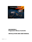
Maximiser Progressive Controller
Street & Race Model Owner's Manual
44 (0) 01302 834343 • www.noswizard.com
Introduction
Congratulations on purchasing the Maximiser for the ultimate in progressive nitrous
control. By following the proceeding instructions you will ensure safe and reliable
nitrous performance. If for any reason you have questions please use our message
board, contact your nearest dealer, or contact us direct for assistance. Your Maximiser
is covered by a lifetime warranty, should you have any problems with the equipment
please let us now immediately and we’ll either repair it or replace it free of charge.
The following pages will give you a thorough explanation of the
features on your STREET and RACE unit.
The features in red represent optional RACE mode programs!
Either the STREET or RACE UNIT can be upgraded to have the
Bottle Contents Indicator feature activated.
Wire the Maximiser as shown in the following wiring diagrams. The shorter you keep
the red, blue and black wires the more efficiently the unit will work.
Not following the advice below may result in system damage or at worst serious
engine damage.
1) Do not activate the unit without the black wire connected to ground.
2) Do not connect any of the wires to +12V except the orange.
3) Do not connect any solenoids to the Maximiser which have not had the coil
resistance checked and tested against the manufacturers specification. Replace
coils that are not to specification, as faulty coils can burn out the Maximiser power
Mosfets.
4) Do not connect the purple wire to any load greater than 10 amps without the
use of a relay. Do not connect directly to an aftermarket ignition system as this may
cause interference.
5) Do not mount the unit close to a high performance ignition system or HT leads.
Note: Mount the Maximiser as close as possible to the solenoids. If you need to
extend the wiring harness for any reason take care to use the same grade of wire
as used on the Maximiser. Using a smaller grade may cause electrical problems.
Dimensions:
7"L x 2.75"H x 1.25"D
- OPTIONAL -
TPS Switch Installation
1. Using a "digital" volt meter and with the ignition switched "on", determine which
wire on the throttle position sensor gives either a 0 to 5 volt reading (or the reverse
on some applications) as the throttle is activated. When you have determined the
right wire on your TPS sensor, connect the white wire from the TP1 unit to it.
2. For direct feed from battery: Wire the remaining wires as shown (following
page), but leave the pink (pink wire will activate the solenoids) and red wires
disconnected. a) Turn the ignition on. b) Press and hold the TPS set button an
connect the red TPS wire to power (12 V). Release the set button and the led should
illuminate for 2 seconds. c) Open the throttle using the pedal to the position that
you want the Nitrous System to activate (between 80 and 90% of full throttle) and
then briefly press the set button again. The LED should illuminate for 2 seconds
again and then switch off, which indicates that the unit is ready for use. Opening
the throttle to WOT should now cause the LED to illuminate. d) Now wire
remaining wires with power switched off.
3. For connection to 12V ignition: Wire the remaining wires as shown but leave
the pink (pink wire will activate the solenoids) disconnected. a) Press and hold down
the set button with the ignition turned off. b) Turn on the ignition switch to IGN only
(not Start) and release the set button. The LED should illuminate for 2 seconds
after you release the set button. c) Open the throttle using the pedal to the position
that you want the Nitrous System to activate (between 80 and 90% of full throttle)
and then briefly press the set button again. The LED should illuminate for 2
seconds again and then switch off, which indicates that the unit is ready for use.
Opening the throttle to WOT should now cause the LED to illuminate. d) Now
connect the "pink" wire as shown after the unit has been set.
4. Operating the pedal/throttle past the "set" position should activate the Pulsoids,
at this time the LED should light up.
Mounting Instructions
The Maximiser unit has a slot on the back
of the case which can be used in
conjunction with the hardware provided to
mount the Maximiser however you feel
appropriate. The mounting bracket can
also be bent to provide additional
mounting options.
Slide the flat head screw shown into the
groove on the back of the Maximiser. Then
screw down the bracket to your chosen
surface.
Micro Switch Diagram
MAXIMISER
Purple - GND output to activate a relay
10 amp max load
Black
White
Digital Progressive Control
Blue
Orange
Nitrous
Solenoid
SW2
SW1
20 AMP FUSE
Fuel
Solenoid
+
Battery
SW3
White
TPS Diagram
MAXIMISER
Purple - GND output to activate a relay
10 amp max load
Black
White
Digital Progressive Control
Blue
Orange
Nitrous
Solenoid
SW2
SW1
+
20 AMP FUSE
Red
Fuel
Solenoid
Red
Battery
Pink
White
Black
Red
Getting Started
Once the unit is fully wired properly you are ready to power the Maximiser up and
scroll through the screens of features.
Turn the arming switch to the "ON" position and you will see the product ID screen.
MAXIMISER 9000 (version no.) STREET (means the ‘STREET’ preset has been
selected) 1848 (unit serial number).
Note: The Maximiser has been pre-programmed from the factor y with the
following settings;
Menu 1
(Power / Time Menu) - Initial Delay 0 Secs, Build Time 5 Secs, Start Power 25%,
Final Power 100%, Run Time ‘Off’.
Menu 2
(Reset Power/Time Menu)- Reset to Start + ‘00%’, Reset time ‘Off’
Menu 3
(Calibrations) – Frequency 20 Hz, Nitrous Delay 0.10 Secs, Retard output on @
30%, Max Flow 100%
Menu 4
(Saved Settings) – Load, Save.
Overview
1) Initial screen if wired properly and power switch activated. 2) Comes on after
screen 1 in sequence. Push up arrow on front panel for automatic scroll of functions
and settings. 3) Press up arrow on front panel to go to main menu and make changes
to settings. 4) Screen that needs to be shown for Maximiser to operate in race mode.
5) Main menu to select menu of functions. Use arrows on front panel to select.
1
2
4
3
5
Back
Next Function
OFF/ Decrease
ON/Increase
Menu 1
Initial Delay:
The time the nitrous system can be delayed from activating after
the throttle switch is operated can be adjusted between 0.1 and
9.9 seconds. Selecting less than 0.1 will turn this feature OFF.
Example: A 1.5 delay will turn the nitrous system on 1.5 seconds
into the run after switch activation. Function will not affect or
cause gear change delays.
Build time:
The time it takes the nitrous power to build up from the “start”
percentage to the final power, can be adjusted between 0.1 to
9.9 seconds.
Example: A 2.5 build time will result in taking 2.5 seconds from
start power to end power. If 'reset' (menu 2) function is turned
on build time will be taken into account each gear change. Refer
to Menu 2 for more options.
Start Power:
The percentage of full power that is delivered when the system
is first activated is adjustable from 15% to 100%. Can be set
lower or higher than end power.
Example: A) Set lower than end power for optimal traction and
smaller initial power delivery. B) Set higher than end power to
spool turbo or make earlier power until boost peaks on a s/c.
Final Power:
The percentage of full power that is delivered at the end of the
build time is adjustable from 15% to 100%. Can be set lower or
higher than start power.
Example: A) Set higher then start power for standard full power
later in the rpm range where a motor can handle more nitrous
safely. B) Set lower than start power once turbo or s/c is making
peak boost and providing the power needed.
Run Timer:
The run time that the nitrous system is activated for, can be
adjusted to restrict the system operation to a desired length of
time after the initial activation. The range of adjustment for this
feature is OFF-4.1 to 20 seconds.
Example: Nitrous is used to spool turbo and once peak boost is
reached nitrous can be turned off completely. Same applies once
a s/c reaches peak boost levels.
Menu 2
Burn-Out Feature:
Please note that in 'Street' mode this feature can only be used as
a 'Nitrous Free' operation (0% power). The Race mode chip is
required to unlock the full potential of this feature. Range of 20100% power
Using the up and down keys will scroll the options between:
A) 'On Button Push' – This allows the user to exit the burn-out mode at any time by pushing a key. Doing this allows the unit to become 'Race Ready'.
B) 'On 1 Operation' – The unit will become ‘Race Ready’ after one Burn-Out operation
(one throttle operation). To exit this straight to 'Race Ready' without using the Burn-Out
operation press any key.
C) 'On 2-10 Operations' – As above but after 2-10 Burn-Out operations.
Reset Options: The reset function is mainly intended for
manual transmission applications when you want the Maximiser
to reset every gear change.
A) Reset Off/Hold - The unit will ‘hold’ at whatever % power you
release the throttle and continue from that % when you press the
throttle again.
B) Reset to Start +/- - Maximiser will reset to start power after
each de-activation and activation of throttle/gear change. Reset Power Level - With this
option in use every time you cycle the throttle switch "on" and "off" the Maximiser will increase
the "reset" start power setting by an amount that is adjustable between -30 and +30%, i.e. if
you choose this +/-XX% option and set the value to 10% with the Start Power set at 20% the
first time you reset (as you back off the throttle), the restart power level will be 30%, reset
again and it restarts at 40%, this will continue up to 8O%. The opposite would occur if you
selected -10%.
Reset Time:
Time after each gear change until reset activates. Ranges from
-3 to +3 seconds.
N20 Pressure Offset:
This option allows the user to slowly reduce the fueling of the
system to compensate for nitrous bottle pressure loss (range of
0-15%).
Using the up and down keys cycles the option between ‘OFF’ and
a value between (MIN) 3.0 S and (MAX) 19.9 S. This is the delay
time before the fuel will start to be reduced.
Example: A fuel reduction of 10% and set at 4.5 seconds will cause the fuel pulsoid to flow
10% less fuel 4.5 seconds into the run and stay this way for the remainder of the run until
the nitrous system is de-activated.
Menu 3
Frequency Adjustment:
Different solenoids pulse best at different frequencies. To allow
the Maximiser to be used with all t ypes of solenoids the
frequency can be adjusted to achieve optimal results. The range
of adjustment for this feature is 8 to 50hz. Competitors solenoids
work best at 11-16hz. Highpower solenoids work at 20+hz for
a smoother delivery.
Nitrous Delay:
The activation time of the nitrous can be delayed relative to the
fuel activation. This feature eliminates initial lean-out, which all
systems with pipe lengths longer than 3” will suffer to some
degree. Fuel pressure is much lower than nitrous pressure so
the nitrous solenoid should be delayed until the fuel catches up.
Problem becomes worse the higher the power demands. Range
of OFF- 1 second.
Fuel Delay:
Adjust up to the desired setting your vehicle requires. This
setting will delay the opening of the Fuel solenoid output only
to match the slower delivery time of the nitrous on some ‘air box’
or dry systems. Common for bike nitrous systems. Range of
OFF- 1 second.
N20:Fuel Ratio:
Adjusts the ratio between nitrous and fuel by limiting one pulsoid
to a lower overall percentage than the other. Nitrous pulsoid is
always fixed at 1 and fuel pulsoid ranges from .8-1.2 to either
richen or lean out mixture.
Note: Be careful with this setting as it gives you the ability to
lean out the system which could if used incorrectly cause
damage to your engine.
Ignition Retard Output:
This is an adjustable switched output that can be set to activate
at any percentage of power and is typically connected to an
aftermarket ignition system with a switched retard feature. The
range of adjustment for this feature is OFF to 100%.
Example: An aftermarket ignition like MSD has a retard feature
that can be activated by the Maximiser at a given nitrous power
level.
Max Pulse Width:
Range of 70 to 100%. The nitrous solenoid will start to flow 100%
earlier than 100% because of the high pressure situation. The fuel
solenoid is still pulsing and delivering fuel accurately to 95-100%
because of a lower pressure. This can cause a lean out, so match
the percentage for when the nitrous side starts to flow wide open
and the fuel side will stop pulsing and go wide open also. U.S.
solenoids can be as low as 60%. Highpower solenoids are about 85-95%.
Set-Up: a) Turn the bottle off and have no nitrous pressurising the system. b) Activate the
system while listening to the nitrous solenoid pulsing and watching the nitrous bar
percentage on the Maximiser screen (this may require 2 people). c) Set this feature up to the
percentage where the nitrous pulsoid stopped pulsing compared to the nitrous bar
percentage (90% when the nitrous solenoid stopped pulsing would indicate a 90% setting).
N20 Timer Set (Bottle Contents Indicator):
These settings allow the usage of nitrous oxide to be measured
by the Maximiser.
A) Power: Using the arrow keys select the power level your
system is currently using. E.G if you’re using 25 BHP jets, select
25 BHP.
B) Weight: Using the up and down keys, select the total bottle capacity (in nitrous pounds).
If the bottle isn’t full, select the weight of the nitrous remaining.
C) To Reset: Once you’ve adjusted the 'Contents Indicator' settings then you must reset the
counter for it to work. Once you do this a figure in the top right of the ‘RACE READY’ screen
will show. This indicates the approximate nitrous remaining time you have in
seconds. You should also use the reset feature whenever you get your bottle/'s re-filled.
Debounce Delay:
Allows the user to reduce any possible keypad interference from
powerful ignition systems. If you use a powerful ignition system
tr y adjusting the setting to around 0.10 s. If you still think
interference is a problem then please contact us for further help.
Menu 4
File Menu:
This is a 10 store data log in which you can store up to 10 sets
of adjustments which you may want to repeat without having to
make notes of each individual setting and reload individually when
required. With this unique feature you can save ALL the
adjustments made in an individual numbered log for reloading at
a later date.
File Load: Select saved file and load settings.
Activated Screen Bars and Percentages
Once the unit has been activated (when WOT is reached) from the ‘Ready to Race’ screen
it will display 2 bar graphs and 2 x % figures which indicate the current power level. If the
throttle is released for any reason the unit will display ‘THROTTLE OFF’. This indicates the
unit is waiting to see a WOT signal and has made any adjustments that you may of selected
in menu 2. If WOT is not re-activated within 5 seconds the unit re-sets to the ‘Ready to Race’
screen to begin the original sequence of settings.
Test Mode
The unit has a ‘Test mode’ so inputs/outputs and system functionality can be fully tested. a)
Have the unit powered down b) Hold the left and right arrows while powering up the unit.
c) When the first screen is displayed release the keys and the ‘Test Mode? Yes/No’ screen
should appear. Press the up arrow to enter. d) The screen will then show each keypad arrow
individually. You press each keypad arrow on the physical unit that corresponds with the
screen arrow to make sure the keypad is working correctly. e) The unit will now show the
following screen to test that the pulsoids work properly. Pressing
the following keys will activate the corresponding outputs. This
allows you to test each output and it’s wiring separately. Pressing
the up arrow labeled N2O will fire the nitrous solenoid. Pressing
the down arrow labeled FUEL will fire the fuel solenoid. Pressing
the left/back arrow labeled N&F will fire both the nitrous and fuel
solenoids. Pressing the forward/right arrow labeled RETARD will
trigger an external retard box.
Important: Avoid injecting nitrous only into the engine, running or not. A ‘Static Test’ can
also be performed using this function. Consult your nitrous system installation manual or
retailer for more information about the ‘Static Test’.
Reset Unit to Factory Defaults
If you wish to clear all the memory in the unit and return to factory defaults for whatever
reasons then follow these sequence of events. a) Have the unit powered down b) Hold the
up and down arrows while powering up the unit. c) After main initial screen appears, release
buttons and unit will show another screen with the reset option. d) Select 'reset'.
Note: Re-setting to factory defaults will cause all saved files to be lost.
Upgrade Feature
Above the word 'reset' you will also have the option to 'upgrade’. Selecting upgrade will take
you to the upgrade screen where the unit serial number will be displayed. For an upgrade to
‘Race’ or ‘Bottle Contents Indicator’ to be possible you must first acquire an unlock code from
Highpower Systems (or nearest agent/retailer). The unlock codes are unique to each unit but
for us to give you the code you must have the unit serial number to hand. Important: Do
not attempt to enter a code without being sure it's correct. Entering an incorrect code 5 times
will lock the unit out. If this occurs the unit will have to be returned and have a new chip
installed. Example: code is ‘234 165 32’. You can enter the upgrade code by using the up
and down keys until the correct 2 or 3 digit number value is reached, then using the right
arrow to move to the next number. Note: There are 3 spaces to enter numbers. Keep holding up arrow to reach 234 to fill space one, etc. Once all numbers are correct, press right
again to enter the code. Providing the code is correct the screen should display ‘Upgrade
Ok’.
Troubleshooting
Problem
Cause
Screen flashes back and forth from
'Throttle OFF' to bars/percentages.
Check that the white wire has a good
connection.
Unit does not power up.
Check power, ground connections, and
fuse.
Unit turns off and comes back on
intermittently.
Check that the white wire has a good
connection. If using a micro switch
check adjustment. If using a TP1
check throttle angle settings. Check
ground connection.
Upgrade code does not work.
Make sure numbers are being added
correctly. Example: 138 does not mean
1 then next number is 3, etc. First
number must scroll all the way to 138
as one number and then move to the
next set.
NOTES:
_______________________________________
_______________________________________
_______________________________________
_______________________________________
_______________________________________
_______________________________________
_______________________________________
_______________________________________
_______________________________________
_______________________________________
Lifetime Warranty
Highpower products are covered by a Lifetime warranty against any defects for
the lifetime of the original purchaser. This warranty does not cover any damage
done by modifying or tampering of the original product outside of a Highpower
representative. If any part becomes faulty, please contact a Highpower office
with proof of purchase for an exchange or warranty coverage.
Importer for and affiliated with:
Highpower Systems International Ltd.
Rands Lane, Armthorpe Doncaster
South Yorkshire, England
DN3 3ER, UK.
44 (0) 01302 834343
www.noswizard.com