1
Master Project
LPM - IPR - STI
ÉC O L E PO L Y T E C H N IQ U E
FÉ DÉR ALE D E LA U SAN N E
Winter Session 2005-2006
Damien Perritaz
Professor : Peter Ryser
Assistants : Eric Meurville, Léandre Bolomey
ECOLE POLYTECHNIQUE FÉDÉRALE DE LAUSANNE
POLITECNO FEDERALE DI LOSANNA
EIDGENÖSSISCHE TECHNISCHE HOCHSCHULE
SECTION DE MICROTECHNIQUE
ÉC O L E PO L Y T E C H N IQ U E
FÉ DÉR ALE D E LA U SAN N E
LABORATOIRE DE PRODUCTION MICROTECHNIQUE
TRAVAIL PRATIQUE DE MASTER
Microtechnique
Titre du travail:
GlucoBox System
Candidat:
Damien Perritaz
Professeur:
Prof. Peter Ryser
Assistants:
Eric Meurville, Léandre Bolomey
Section:
Microtechnique
Enoncé :
Lorsqu’il est implanté dans un patient, le capteur de glucose du LPM est contrôlé par un
transceiver positionné à proximité du site d’implantation. Il est prévu que ce transciever soir
lui-même contrôlé à travers une liaison RF par un boı̂tier externe avec afficheur et boutons
de contrôle. Outre sa fonction de contrôle (programmation de la fréquence des mesures de
glycémie, programmation des seuils d’alerte et des alarmes acoustiques et tactiles), ce boı̂tier
assure aussi la fonction d’un “data logger” capable d’enregistrer toute une série de mesures,
de les traiter (calculs de tendance) et de les visualiser. A terme, l’interopérabilité avec un
PC ou un PDA devra être assuré. Ce boı̂tier de contrôle sera alimenté par batterie. Il devra
être compact et un soin tout particulier sera porté quant à l’esthétique du boı̂tier. Il aura
pour cœur un dsPIC de Microchip et la partie RF sera reprise d’un projet précédent. Le but
de ce travail est de réaliser intégralement ce boı̂tier de contrôle: électronique, logiciel et design.
En outre les étudiants établiront d’une part la spécification du protocole de communication
RF entre le boı̂tier de contrôle et le transceiver et d’autre part, contacteront des patients ainsi
que du personnel soignant pour élaborer un cahier des charges fonctionnel de l’appareil.
Remarques :
Le candidat établira un planning de travail qui sera discuté à la fin des deux premières semaines de travail. Ce planning comprendra des échéances à dates fixes qui seront l’occasion
de faire le point sur l’avance du travail et permettront éventuellement de modifier la démarche
en fonction des objectifs à atteindre.
Un rapport dactylographié en 3 exemplaires comprenant en son début l’énoncé du travail suivi
d’un résumé d’une page sera remis le 24 février 2006 à 12 heures au plus tard. La couleur
n’est tolérée que sur des schémas qui ne seraient pas lisibles en noir.Un résumé d’une page
sera établi selon le canevas pris sur le serveur du LPM et remis séparément au professeur
(images et figures en noir et blanc, il sera édité dans une brochure).
Une défense de 45 minutes (environ 25 minutes de présentation et démonstration, plus 20
minutes de réponses aux questions) aura lieu dans la période du 13 au 20 mars 2006.
Le Professeur responsable
Lausanne, le 8 novembre 2005
L’assistant responsable
LPM-IPR-STI
Abstract of Master project
February 24, 2006
GlucoBox System
Sadasing Kowlessur, Damien Perritaz, Micro-engineering
Professor: Prof. Peter Ryser
Assistants: Eric Meurville, Léandre Bolomey
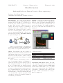
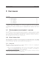
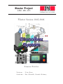
Introduction. A bio-sensor is currently under development at the LPM. The goal is to
measure glucose level in blood of diabetic patients who need continuous glucose level monitoring. The objective of this project is to
build a control device capable to communicate
with the sensor and to transfer data to a PC.
A request can be triggered by user or scheduled at a chosen frequency. The global concept is a system including the control device
itself and a PC software: GlucoBox System
is depicted in figure below.
RF link
Results. Currently, all functional tasks are
achieved, according to project requirements.
However, only one main requirement has not
been reached: RF range is less than the expected 3 m. In spite of poor RF performance,
the concept of the GlucoBox System has been
validated.
bio-sensor
PC
user
control device
The project is divided into four main steps:
research of solutions, design and manufacturing, software development and final tests.
Work. The starting point was to study existing solutions and to evaluate patients’ needs.
After having defined the project requirements,
the selected solution was to build a custommade system rather than using an existing
host device.
Our work lead to user-friendly control device; by pressing a button, a reading is requested from the bio-sensor and the glucose
rate is displayed within 5 s. If glucose level
is out of normal range, an alarm resounds.
The device can be scheduled to automatically
request a reading without patient’s intervention. Measurements are stored in the device
itself. Later on, the patient can transfer all
measurements to a PC via USB with the help
of a user-friendly computer program. Data
can then be exported for further analysis by
a healthcare professional.
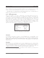
GlucoBox Control Device & Software
Main characteristics:
Dimensions
23 x 62 x 103 mm
Weight
115 g
Power autonomy
7 days
Storage capacity
85’000 measurements
Conclusion and future work. The GlucoBox System performance was evaluated and,
compared to existing products, it fulfills many
characteristics which make it a good foundation for the commercial product. Finally, we
would like to point that for the next step, the
RF part – which is essential in our concept –
has to be improved.
C ONTENTS
Abstract
ii
1 Introduction
1.1 What is diabetes ? .
1.2 Scope . . . . . . . .
1.3 Project overview . .
1.4 Project management
.
.
.
.
.
.
.
.
.
.
.
.
.
.
.
.
.
.
.
.
.
.
.
.
.
.
.
.
.
.
.
.
.
.
.
.
.
.
.
.
.
.
.
.
.
.
.
.
.
.
.
.
.
.
.
.
.
.
.
.
.
.
.
.
.
.
.
.
.
.
.
.
.
.
.
.
.
.
.
.
.
.
.
.
.
.
.
.
.
.
.
.
.
.
.
.
.
.
.
.
.
.
.
.
.
.
.
.
.
.
.
.
.
.
.
.
.
.
.
.
1
1
1
2
2
2 Basic concepts
2.1 State of the art . . . . . .
2.2 Monitor needs . . . . . . .
2.3 Computer interface needs
2.4 Project requirements . . .
2.5 Suggested solutions . . . .
.
.
.
.
.
.
.
.
.
.
.
.
.
.
.
.
.
.
.
.
.
.
.
.
.
.
.
.
.
.
.
.
.
.
.
.
.
.
.
.
.
.
.
.
.
.
.
.
.
.
.
.
.
.
.
.
.
.
.
.
.
.
.
.
.
.
.
.
.
.
.
.
.
.
.
.
.
.
.
.
.
.
.
.
.
.
.
.
.
.
.
.
.
.
.
.
.
.
.
.
.
.
.
.
.
.
.
.
.
.
.
.
.
.
.
.
.
.
.
.
.
.
.
.
.
.
.
.
.
.
.
.
.
.
.
.
.
.
.
.
.
.
.
.
.
3
4
5
7
7
8
3 GlucoBox System
3.1 Control device . . . . . . . . . . . . . . . . . . . . . . . . . . . . . . . . . . .
3.2 Computer interface . . . . . . . . . . . . . . . . . . . . . . . . . . . . . . . . .
13
13
16
4 Control device
4.1 Architecture . . . . . . .
4.2 Embedded peripherals .
4.3 Wireless communication
4.4 Power supply . . . . . .
4.5 Embedded software . . .
.
.
.
.
.
18
19
20
25
30
31
5 Software
5.1 Programming environment: Labview . . . . . . . . . . . . . . . . . . . . . . .
5.2 Functionalities . . . . . . . . . . . . . . . . . . . . . . . . . . . . . . . . . . .
36
36
36
6 Hardware design
6.1 Mechanical . . . . . . . . . . . . . . . . . . . . . . . . . . . . . . . . . . . . .
6.2 PCB layout . . . . . . . . . . . . . . . . . . . . . . . . . . . . . . . . . . . . .
44
44
44
7 Tests and results
7.1 Test conditions . . . . . . . . . . . . . . . . . . . . . . . . . . . . . . . . . . .
7.2 Results . . . . . . . . . . . . . . . . . . . . . . . . . . . . . . . . . . . . . . . .
49
49
49
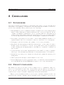
8 Conclusion
8.1 Future work . . . . . . . . . . . . . . . . . . . . . . . . . . . . . . . . . . . . .
8.2 Project conclusion . . . . . . . . . . . . . . . . . . . . . . . . . . . . . . . . .
53
53
53
.
.
.
.
.
.
.
.
.
.
.
.
.
.
.
.
.
.
.
.
.
.
.
.
.
.
.
.
.
.
.
.
.
.
.
.
.
.
.
.
.
.
.
.
.
.
.
.
iii
.
.
.
.
.
.
.
.
.
.
.
.
.
.
.
.
.
.
.
.
.
.
.
.
.
.
.
.
.
.
.
.
.
.
.
.
.
.
.
.
.
.
.
.
.
.
.
.
.
.
.
.
.
.
.
.
.
.
.
.
.
.
.
.
.
.
.
.
.
.
.
.
.
.
.
.
.
.
.
.
.
.
.
.
.
.
.
.
.
.
.
.
.
.
.
.
.
.
.
.
.
.
.
.
.
Acknowledgments
55
Bibliography
59
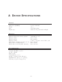
A Device Specifications
60
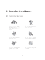
B GlucoBox User Manual
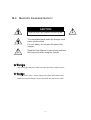
B.1 Safety Instructions . . . . . .
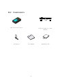
B.2 Components . . . . . . . . . .
B.3 Battery Charger Safety . . .
B.4 Charging The Battery . . . .
B.5 Location Of Controls . . . .
B.6 Display . . . . . . . . . . . .
B.7 Connection GlucoBox Control
.
.
.
.
.
.
.
61
61
62
63
64
64
65
66
C Technical User Manual
C.1 Software Used . . . . . . . . . . . . . . . . . . . . . . . . . . . . . . . . . . . .
C.2 Accessing programming interface . . . . . . . . . . . . . . . . . . . . . . . . .
73
73
73
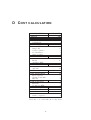
D Cost calculation
76
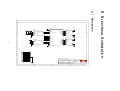
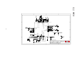
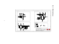
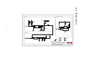
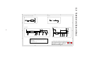
E Electrical Schematics
E.1 Mainboard . . . . . . . . .
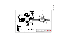
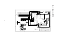
E.2 MCU . . . . . . . . . . . .
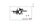
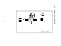
E.3 Peripherals . . . . . . . .
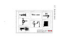
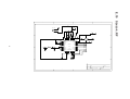
E.4 Power Supply . . . . . . .
E.5 RF . . . . . . . . . . . . .
E.6 USB . . . . . . . . . . . .
E.7 Daughter board . . . . . .
E.8 Temperature Sensor Base
E.9 Sensor: MCU . . . . . . .
E.10 Sensor: RF . . . . . . . .
E.11 Sensor: Level Shifter . . .
.
.
.
.
.
.
.
.
.
.
.
.
.
.
.
.
.
.
.
.
.
.
. . . . . .
. . . . . .
. . . . . .
. . . . . .
. . . . . .
. . . . . .
Device To
.
.
.
.
.
.
.
.
.
.
.
.
.
.
.
.
.
.
.
.
.
.
.
.
.
.
.
.
.
.
.
.
.
.
.
.
.
.
.
.
.
.
.
.
.
.
.
.
.
.
.
.
.
.
.
.
.
.
.
.
.
.
.
.
.
.
. . . . . .
. . . . . .
. . . . . .
. . . . . .
. . . . . .
. . . . . .
Your PC
.
.
.
.
.
.
.
.
.
.
.
.
.
.
.
.
.
.
.
.
.
.
.
.
.
.
.
.
.
.
.
.
.
.
.
.
.
.
.
.
.
.
.
.
.
.
.
.
.
.
.
.
.
.
.
.
.
.
.
.
.
.
.
.
.
.
.
.
.
.
.
.
.
.
.
.
.
.
.
.
.
.
.
.
.
.
.
.
.
.
.
.
.
.
.
.
.
.
.
.
.
.
.
.
.
.
.
.
.
.
.
.
.
.
.
.
.
.
.
.
.
.
.
.
.
.
.
.
.
.
.
.
.
.
.
.
.
.
.
.
.
.
.
.
.
.
.
.
.
.
.
.
.
.
.
.
.
.
.
.
.
.
.
.
.
.
.
.
.
.
.
.
.
.
.
.
.
.
.
.
.
.
.
.
.
.
.
.
.
.
.
.
.
.
.
.
.
.
.
.
.
.
.
.
.
.
.
.
.
.
.
.
.
.
.
.
.
.
.
.
.
.
.
.
.
.
.
.
.
.
.
.
.
.
.
.
.
.
.
.
.
.
.
.
.
.
.
.
.
.
.
.
.
.
.
.
.
.
.
.
.
.
.
.
.
.
.
.
.
.
.
.
.
.
.
.
.
.
.
.
.
.
.
.
.
.
.
.
.
.
.
.
.
.
.
.
.
.
.
.
.
.
.
.
.
.
.
.
.
.
.
.
.
.
.
.
.
.
.
.
.
.
.
.
.
.
.
.
.
F Loading picture in DDRAM
G RF
G.1
G.2
G.3
G.4
G.5
G.6
G.7
G.8
Protocol
IO lines . . . . . . . . . . . .
Data link . . . . . . . . . . .
Main services . . . . . . . . .
Transmit procedure . . . . . .
Receive procedure . . . . . .
Firmware limitations . . . . .
Example 1: sending a packet
Example 2: receiving a packet
77
77
78
79
80
81
82
83
84
85
86
87
88
.
.
.
.
.
.
.
.
.
.
.
.
.
.
.
.
.
.
.
.
.
.
.
.
.
.
.
.
.
.
.
.
.
.
.
.
.
.
.
.
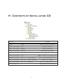
H Contents of Installation CD
.
.
.
.
.
.
.
.
.
.
.
.
.
.
.
.
.
.
.
.
.
.
.
.
.
.
.
.
.
.
.
.
.
.
.
.
.
.
.
.
.
.
.
.
.
.
.
.
.
.
.
.
.
.
.
.
.
.
.
.
.
.
.
.
.
.
.
.
.
.
.
.
.
.
.
.
.
.
.
.
.
.
.
.
.
.
.
.
.
.
.
.
.
.
.
.
.
.
.
.
.
.
.
.
.
.
.
.
.
.
.
.
.
.
.
.
.
.
.
.
.
.
.
.
.
.
.
.
.
.
.
.
.
.
.
.
.
.
.
.
.
.
.
.
.
.
.
.
.
.
.
.
.
.
.
.
.
.
.
.
.
.
.
.
.
.
.
.
.
.
.
.
.
.
.
.
89
89
89
89
90
90
91
91
92
93
iv
GlucoBox System
LPM - EPFL
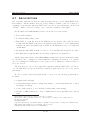
1 I NTRODUCTION
At the LPM1 laboratory, a bio-sensor is currently under development. The main goal of this
sensor is to measure glucose level in blood by using a totally innovative method. The main
application of this sensor is for diabetic patients who need glucose level monitoring.
1.1
W HAT IS DIABETES ?
Diabetes is an illness which occurs as a result of problems with the production and supply
of insulin in the body. Without insulin, our bodies cannot obtain the necessary energy from
our food. Insulin is made in a large gland behind the stomach called the pancreas.
At present there is no cure for diabetes. In order to treat diabetes, the patient’s instantaneous glucose level must be known. The most reliable measurement is actually done by
analyzing the blood. The patient takes a blood sample and with the help of a glucometer, he
can read its instantaneous measurement. Nowadays, portable glucometer helps patients to
have a merely normal life style.
If glucose level is too high (hyperglycemia), the goal of treatment is to lower glucose level
through medication in the form of insulin. On the other hand, if glucose level is too low
(hypoglycemia), patient needs to eat sugar to restore glucose level.
The International Diabetes Federation2 estimates that at least 194 million people in the
world have diabetes.
1.2
S COPE
One of the benefits of using the bio-sensor made by the LPM is to avoid patient from taking
a blood sample. Indeed, the final form of the sensor is a miniature implant which needs only
minor surgery intervention. At this stage of the development of the sensor, a prototype of the
sensor exists. Moreover, a built-in RF3 module will allow measurements to be sent to remote
device for further analysis. The objective of this project is to build a control device capable
of communicating with the sensor, in the frame of a demonstrator bench.
Results and the end of this project may be considered as important guidelines for a
commercialized version of the control device.
1
LPM: Laboratoire de Production Microtechnique, http://lpmwww.epfl.ch/
http://www.idf.org/
3
RF: Radio Frequency
2
1/ 93
GlucoBox System
1.3
LPM - EPFL
P ROJECT OVERVIEW
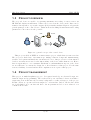
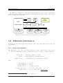
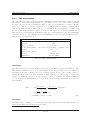
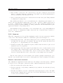
The proposed device is capable of requesting instantaneous reading of remote sensor via
RF link and display measurement. Values can be stored in the device itself. Data can be
transfered at any time to a personal computer (PC) for further analysis. Figure 1.1 depicts the
general principle of the control device. Tasks such as scheduling measurements and loading
parameters to the sensor are also possible.
bio-sensor
RF link
PC
user
control device
Figure 1.1: general concept of the control device
This project is held at EPFL as a winter master project, which lasts for sixteen weeks.
The project is divided into four main steps: finding solutions, design and manufacturing,
software development and final tests. As mentioned before, this project is for a demonstrator
bench, so motivation is focused on the functionality of the device rather than its cost. Hence,
there is apparently no cost constraints. Furthermore, industrialization aspects of the device
are not taken into account in the design due to short duration of this project. For the same
reasons, reliability, electrical and medical compliances are not part of this project.
1.4
P ROJECT MANAGEMENT
This project is multi-disciplinary project. It requires knowledge in electrical design, mechanical design and programming. The work is lead by two students; both are from Microengineering section and have the necessary background to tackle each aspect of the project.
In this context, no specific field was assigned to each student. Indeed, all the three fields
are closely linked one to another and hence, the steps mentioned above were achieved on a
combined-effort basis.
2/ 93
GlucoBox System
LPM - EPFL
2 BASIC
CONCEPTS
Contents
2.1
State of the art . . . . . . . . . . . . . . . . . . . . . . . . . . . . . .
2.1.1 Accu-Chek R . . . . . . . . . . . . . . . . . . . . . . . . . . . . . . .
4
4
2.1.2 CGMS R . . . . . . . . . . . . . . . . . . . . . . . . . . . . . . . . .
2.2 Monitor needs . . . . . . . . . . . . . . . . . . . . . . . . . . . . . .
4
5
2.3
2.2.1
2.2.2
User interface . . . . . . . . . . . . . . . . . . . . . . . . . . . . . . .
External design . . . . . . . . . . . . . . . . . . . . . . . . . . . . . .
5
5
2.2.3
2.2.4
Display . . . . . . . . . . . . . . . . . . . . . . . . . . . . . . . . . .
Measurements . . . . . . . . . . . . . . . . . . . . . . . . . . . . . .
6
6
2.2.5
2.2.6
Alarm . . . . . . . . . . . . . . . . . . . . . . . . . . . . . . . . . . .
Computer link . . . . . . . . . . . . . . . . . . . . . . . . . . . . . .
6
7
Computer interface needs . . . . . . . . . . . . . . . . . . . . . . .
2.3.1
2.3.2
2.4
2.5
Patient interface . . . . . . . . . . . . . . . . . . . . . . . . . . . . .
Doctor interface . . . . . . . . . . . . . . . . . . . . . . . . . . . . .
Project requirements . . . . . . . . . . . . . . . . . . . . . . . . . .
Suggested solutions . . . . . . . . . . . . . . . . . . . . . . . . . . .
7
7
7
7
8
2.5.1
2.5.2
Wrist PDA R . . . . . . . . . . . . . . . . . . . . . . . . . . . . . . .
PCMCIA . . . . . . . . . . . . . . . . . . . . . . . . . . . . . . . . .
8
10
2.5.3
2.5.4
Other devices . . . . . . . . . . . . . . . . . . . . . . . . . . . . . . .
“Home-made” system . . . . . . . . . . . . . . . . . . . . . . . . . .
10
11
2.5.5
Selected system . . . . . . . . . . . . . . . . . . . . . . . . . . . . . .
11
A glucose monitoring system is generally composed of three parts: a sensor gives glucose
rate, a control device manages values given by the sensor and a computer software for post
analysis. This chapter presents some usual glucose monitors with their specifications. With
the recommendations of a healthcare professional, a list of requirements has been established
for such systems.
Some suggested solutions were studied and a solution has been proposed, with the choices
and their explanation. It is important to know that the study has been made on the basis
that only a sensor exists.
3/ 93
GlucoBox System
2.1
LPM - EPFL
S TATE OF THE ART
There is a huge potential market around medical devices. Approximately five billion CHF are
invested every year for the development of glucose monitoring systems by a large number of
firms. It is very difficult to obtain competitive devices. Several systems have been proposed,
but only a few of them are currently used in Switzerland.
2.1.1
ACCU -C HEK
R
[1]
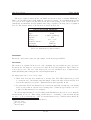
This system sold by Roche Diagnostics is the most used in Switzerland, and is commonly
known to many diabetics. The patient usually manages himself his medication between
medical appointments and can react according to his glucose level.
Patient takes his rate three to six times per day to check his level and takes medication
if needed. For measurement, a small drop of blood is taken, (generally at the fingertip) with
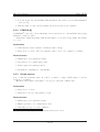
a reactive strip, and the latter is inserted into the device shown in figure 2.1(a). After five
seconds, the glucose rate value is displayed on the screen, in a large number format. Date
and time are also indicated. Then the patient must write the value on a notepad, for further
analysis.
The system (including the device, the strips and the notepad) is usually kept in a little
bag. Its size is about 180 x 100 x 30 mm and weighs 60 g. A compact version exists without
the bag (115 x 56 x 30 mm). Moreover, the device has the capability to store up to five
hundreds measurements. The patient or the doctor1 can transfer data to a computer for
analysis, via an infrared connection to an adapter connected to the computer. A software is
available for the patient to help him to manage and analyze his measurements.
The whole system, is an effective manner to regulate glucose rate. Indeed, the monitoring
device is very easy to use and fits appropriately the needs. However, it is not a continuous monitoring system and blood sample is required, which may be uncomfortable for some
persons, especially children.
2.1.2
CGMS
R
[2]
In certain cases, the doctor often prescribes the CGMS2 , manufactured by Medtronic MiniMed, to collect accurate and continuous glucose levels. Data are analyzed to diagnostic hidden blood sugar patterns such as hypoglycemia and to evaluate the reaction after a change
in the medication.
A tiny sensor is introduced under the skin of the abdomen. After insertion, the sensor is
secured with tape to keep it in place. A wire connects the sensor to the monitor, generally
held in the pocket. The system automatically takes measurements every five minutes during
a period of three days and stores them. During this period, the patient must continue to take
his glucose level with a standard system, because CGMS measurements are not calibrated;
this is done off line. For this reason, no measurement is displayed.
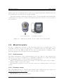
The monitor shown in figure 2.1(b) is of size 90 x 70 x 22 mm and weighs 115 g. Data
are transfered to a computer via a serial cable. A software is available for the doctor to
1
2
In this report, doctor is a generic term used for all healthcare professionals
CGMS: Continuous Glucose Monitoring System
4/ 93
GlucoBox System
LPM - EPFL
manage diabetics’ personal information and corresponding measurements. Batteries used are
non rechargeable ones and have two months’ lifetime.
The main advantage is that this low invasive device can automatically take measurements
continuously for a long period of time. Nevertheless, this device can not be used for glucose
level regulation.
(a) Accu-Chek Aviva
(b) CGMS Gold System
Figure 2.1: commonly used monitor devices found on the Swiss market
2.2
M ONITOR NEEDS
In order to identify the real needs of diabetics using such devices, it is important to discuss with concerned persons. For this purpose, a discussion has been held with a nurse3
in diabetology from the CHUV4 . With the help of her recommendations, a summary of the
important patient’s needs are listed in the next paragraphs.
2.2.1
U SER
INTERFACE
The main requirement is to have a system which is easy to use. Indeed, both young and elder
diabetics do not know necessarily how to manipulate technical devices. The system must
have a minimum number of buttons, with a user-friendly interface.
When a measurement is requested by pressing on a button, the delay for the reading to
be displayed must be as short as possible.
If rechargeable batteries are used, the time between two charging must be as long as
possible.
2.2.2
E XTERNAL
DESIGN
The system must have more or less the same dimension and weight as a mobile telephone. It
should easily fit in a pocket or carried in a bag (especially for women).
3
4
Mrs. Irma Blanco
CHUV: Centre Hospitalier Universitaire Vaudois
5/ 93
GlucoBox System
LPM - EPFL
A watch format is not a good solution. In European culture, people suffering from a
disease do not want that their situation is known, as it is the case in other countries like
USA. Moreover, not everybody wear watches or prefer their own one, especially for women
and sportsmen.
2.2.3
D ISPLAY
Another important point is to have a large display with clearly visible values. Indeed, one of
the complication of diabetes is angiopathy5 , resulting to a lower vision. It is also important
to be able to see value during the night, so a retro-lighting is needed. Moreover, contrast
must be sufficient so that readings can also be made under excessive illumination (example,
in sunlight).
There are different units for glucose rate. In Switzerland, mmol/l is used in current
systems and values represented in these units are meaningful to diabetics. The measurement
range in mmol/l is from 0 to 30. One decimal precision is required for values under 12.
Patients are accustomed to current systems in which date and time are also displayed
with measurement.
A trend indication could help the patient to anticipate his medication.
2.2.4
M EASUREMENTS
Automatic measurements and storage guarantee a regular data acquisition for further analysis.
A measurement every ten to fifteen minutes seems to be sufficient, but a lower frequency can
fail to show rapid evolution.
The patient can also request his glucose rate up to date for his auto-regulation. However
the number of acquisition per day requested by the patient could be limited to avoid a paranoia
behavior.
2.2.5
A LARM
The normal glucose rate is between 4 and 8 mmol/l. If the rate is out of this range, it could
be dangerous. An alarm can limit the problem in these situations. The glucose rates given
above are general values, alarm level should be configurable differently for each patient.
Below the normal range, the patient must take rapid sugar. When the blood glucose level
falls below 2 mmol/l, there is a risk of coma. Hypoglycemia alarm is especially important
during the night or during sport.
An hyperglycemia has no instantaneous impact but is dangerous in the long run; it can
generate angiopathy. Hyperglycemia is generally not detected by the patient, an alarm can
reduce the risk of complications.
Generally alarm on medical devices, such as insulin pump, are audible, vibrating and
visual. However, even though the patient should have the possibility to deactivate if desired,
some alarms must continue to operate.
5
disease of the blood vessels
6/ 93
GlucoBox System
2.2.6
LPM - EPFL
C OMPUTER
LINK
A communication with a computer is used for data transmission and analysis. The majority
of current systems needs an intermediate device for data transfer, such as a docking station.
This intermediate device should be avoided, direct link is preferable.
2.3
C OMPUTER INTERFACE NEEDS
A user-friendly interface must be available on the computer to manage the communication
with the device. This interface can be used by both the patient and the doctor, but only
some functionalities are reserved for the doctor.
2.3.1
PATIENT
INTERFACE
The interface should principally offer the opportunity to download and store the data and
display a graphic for a day, week or month. Other information include an average (on a day,
week or month basis) and score (in percent) of the time in which the patient was in, over or
under the normal range.
2.3.2
D OCTOR
INTERFACE
The doctor will certainly follow many patients, a multi-patient management should be set up.
His interface should be able to communicate with different devices and store data in adequate
folder.
To avoid errors from patient manipulation, erasing data stored in the monitoring device
must only be made by the doctor. Thus data will not be lost between two medical appointments (time between two appointments may vary from 1 to 6 month, depending on the
severeness of the diabetes).
More sophisticated data analysis tools must be available for healthcare professionals. For
example, the doctor should be able to superpose weekly graphics or make statistical analysis.
2.4
P ROJECT REQUIREMENTS
The systems presented in sections 2.1.1 and 2.1.2 are complementary, but no single system
exist. Such device, associated with the sensor developed in the LPM, would have the following
characteristics:
• continuous glucose monitoring without patient intervention
• data stored in the device itself for a long period of time
• display of measurement on request for auto-regulation
The monitor requirements, based on section 2.2 are shown on table 2.1. The computer
user interface must have main functionalities presented on section 2.3. They are shown on
table 2.2.
7/ 93
GlucoBox System
LPM - EPFL
MONITOR REQUIREMENTS
User interface
Interface
easy to use
Autonomy (min)
7 days
Acquisition time (max)
5s
External design
Look
attractive
Size (max)
120 x 80 x 30 mm
Weight (max)
200 g
Display
Content
value, date, time, trend
Value dimensions (min)
20 x 10 mm
Units format
mmol/l
Precision
one decimal place
Retro-lighting
yes
Measurements
Automatic
yes
On request
yes
Storage capacity (min) 3 months measurement
at 10 minutes interval
Alarm
Primary format
audible
Mute mode
yes
Glucose rate thresholds
configurable
Computer link
Intermediate device
none
Wireless communication with bio-sensor
Range (min)
3m
RF compatibility
medical specifications
Table 2.1: monitor requirements
2.5
S UGGESTED SOLUTIONS
This section presents some interesting solutions with their advantages and disadvantages.
2.5.1
W RIST PDA
R
[3]
The LPM was interested in having an attractive product, such as a watch. The Wrist PDA6
proposed, is based on Palm OS7 ; the software development is done directly on a Palm or with
an emulator.
An RF interface must be developed using available interface on Wrist PDA (USB8 or
6
PDA: Personal Digital Assistant
OS: Operating System
8
USB: Universal Serial Bus
7
8/ 93
GlucoBox System
LPM - EPFL
COMPUTER INTERFACE REQUIREMENTS
User interface
Interface
easy to use
Presentation
graphics with buttons
Data management
Presentation
graphic
Storage
raw format
Export format
*.csva
Monitor control
Data download time (max)
2 min
Data erase
yes
Configuration
yes
This file format is often used to exchange data between disparate applications.
a
Table 2.2: monitor requirements
IrDA9 ).
A DVANTAGES
• Computer software allowing data transfer via USB exists.
• Comfortable display screen: 160 x 160 pixels, 16 level grayscale, backlight and a touch
screen interface.
• Attractive product for a demonstrator bench, especially with a flexible circuit in the
watch bracelet.
D ISADVANTAGES
• Interface limitations:
– Slave USB interface: communication must be established by a master device. This
requires subsequent coding and only few devices can be found on a market.
– IrDA interface: in addition to RF link, another wireless module is needed, which
complicates the integration.
• Multi-target development necessary: solution requires software development for three
different targets (Wrist PDA, RF interface device and computer)
• Dependency of a commercial product: the price, availability10 and development tools
of the system depend on the evolution of this product. It can be a solution for a
demonstrator bench, but not for future development.
9
10
IrDA: Infrared Data Association; wireless optical communication
NB: On February 2006, Fossil seems to have discontinued this watch
9/ 93
GlucoBox System
LPM - EPFL
• Low autonomy: the current Wrist PDA watch has only 3 days of power with 30 minutes
of use per day.
• Watch format: for the reasons explained in section 2.2.2, it is not suitable.
2.5.2
PCMCIA [4]
A PCMCIA11 card can be used with many devices such as notebooks and PDA. Developing
this kind of card is possible.
A hardware design integrating a RF module must be done and corresponding driver must
be coded.
A DVANTAGES
• Same interface with computer or PDA (a Palm or iPaq).
• Large choice of device. The development could be done on a computer or a PDA.
D ISADVANTAGES
• Multi-target development necessary.
• Dependency of a commercial product.
• Time required for writing a driver.
• Mechanical constraints for compatibility.
2.5.3
OTHER
DEVICES
Lots of embedded systems exist. It could be possible to adapt a MP3 player or mobile
telephone for example.
Hardware and software part must be developed to integrate a RF module.
A DVANTAGES
• Large choice of device.
• Attractive look for a demonstrator bench.
D ISADVANTAGES
• Multi-target development necessary.
• High dependency of a commercial product.
• Generally developer tools not available.
11
PCMCIA: Personal Computer Memory Card International Association
10/ 93
GlucoBox System
2.5.4
LPM - EPFL
“H OME - MADE ”
SYSTEM
An other solution is to entirely develop a system. It avoids limitations from another device
to match the project requirements.
A DVANTAGES
• Complete knowledge of the system, without intermediate “black boxes”.
• Not dependent on a commercial device. It is better for a long term basis.
• Only two targets in software development: computer and control device.
• All mechanical parts fit in a unique enclosure.
• Only necessary components used: this allows simple optimization for longer autonomy.
• Format, autonomy could be freely chosen.
D ISADVANTAGES
• Development is longer, in case of a demonstrator bench.
• Difficult to have a small and attractive device.
• Cost of development is generally high.
2.5.5
S ELECTED
SYSTEM
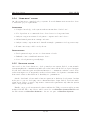
As seen above, the best solution is to develop entirely a new system. Indeed, a custom-made
system simplifies the communication link between the sensor and the PC, as depicted in figure
2.2; all other solutions require an additional interface to communicate with the control device
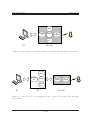
as shown in figure 2.3. Consequently, as there is less software development constraints in the
home-made solution, this allows more flexibility for optimizations.
On the other hand, a home-made solution requires more hardware development, but this
is the price to pay for developing a more efficient hardware design. Indeed, in a home-made
solution it is easier to restrict components to functional requirements only, thus the system
will be energetically effective.
Finally, our proposed custom-made solution will use the USB port as it is widely present
in almost all PC. The control device will be referred to as GlucoBox Control Device and
the PC software as GlucoBox Software – the two are part of GlucoBox System.
11/ 93
GlucoBox System
LPM - EPFL
Display
Computer
link
Buttons
RF
transceiver
Storage,
alarm, ...
S1
S2 + H1
Figure 2.2: custom-made concept (Sx: software development, Hx: hardware development)
Display
Computer
link
Buttons
Control
device link
RF
transceiver
Storage,
alarm, ...
S1
S2
S3 + H1
Figure 2.3: concept based on an existing host (Sx: software development, Hx: hardware
development)
12/ 93
GlucoBox System
LPM - EPFL
3 G LUCO B OX S YSTEM
Contents
3.1
3.2
3.1
Control device . . . . . . . . . . . . . . . . . . . . . . . . . . . . . .
3.1.1 External aspect . . . . . . . . . . . . . . . . . . . . . . . . . . . . . .
13
13
3.1.2
3.1.3
Manipulations . . . . . . . . . . . . . . . . . . . . . . . . . . . . . .
Connectivity . . . . . . . . . . . . . . . . . . . . . . . . . . . . . . .
14
15
Computer interface . . . . . . . . . . . . . . . . . . . . . . . . . . .
3.2.1 Running the interface . . . . . . . . . . . . . . . . . . . . . . . . . .
16
16
3.2.2
16
Using the interface . . . . . . . . . . . . . . . . . . . . . . . . . . . .
C ONTROL DEVICE
As seen before, the important characteristics of the GlucoBox are its simplicity
reliability of measurement. Hence, our design takes into account these points, as
in details below. But first, we must note that GlucoBox will be used by both
and the patient, the latter being the end user. The doctor can access advanced
GlucoBox only by means of the computer software.
3.1.1
E XTERNAL
of use and
we will see
the doctor
features of
ASPECT
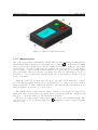
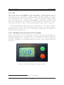
The control device will be in a small form factor, near the size of modern cellular phone.
The main interface of the device is composed of a large LCD1 screen and two push buttons,
as illustrated in figure 3.1. The enclosure is a molded, black, textured ABS2 case. External
dimensions are also given.
Display is also back-lighted, making it possible to read values in dark circumstances.
Other information such as battery level, RF link and warnings, are also available in the form
of icons in the top part of the screen.
Push buttons are large enough and require a minimum pressure to be closed; this prevents
unexpected action from user when GlucoBox is placed in bag for example.
The overall weight of the device does not exceed 115 g.
1
2
LCD: Liquid Crystal Display
ABS: Acrylonitrile Butadiene Styrene is a common thermoplastic used to make light, rigid, molded prod-
ucts
13/ 93
GlucoBox System
LPM - EPFL
Figure 3.1: GlucoBox dimensions in mm
3.1.2
M ANIPULATIONS
One of the most frequent tasks that the patient will perform is requesting
an instantaneous
measurement. This is simply done by pressing once on button A . If the sensor is within
range, a value is then displayed (note that the aerial icon is activated during process). Other
reactions may occur after a value has been acquired: the general trend (↑ or ↓) is shown,
then according to glucose threshold alarm that has been previously set, an audible alarm
may resound (the bell icon is activated by default). One can notice that this process can be
scheduled to occur at regular time interval; in this case, no information is displayed except
in case of an alarm.
When the USB cable is plugged into the device, the latter is automatically recognized
(provided that appropriate drivers have been installed prior to connection). User can then
run host application to start communicate with the control unit. For more information about
functions available in software, go to next section.
The built-in battery of GlucoBox can easily be charged by two methods: energy can be
taken from either an AC adapter (specifications are given in appendix A) – supplied with
GlucoBox – or from the USB port. The first method is quicker.
The device is equipped with a buzzer that canemit
a beep on programmed alarms. The
sound level can be set or deactivated using button B (sound mode can be toggled by holding
button for 2 s).
14/ 93
GlucoBox System
3.1.3
LPM - EPFL
C ONNECTIVITY
C OMMON
CONNECTIONS
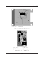
On the side of the device, there are two connection ports: a mini female USB port for communication with a PC and a female DC plug. There is also a reset button (accessible with
the help of a pin) and a charging indicator LED3 (see figure 3.2).
Charging can be done by plugging-in a DC source (maximum 6 V). Polarization in not
important as GlucoBox accepts either case. The device can also be charged via the USB port.
For more specifications on power supply, refer to appendix A.
Figure 3.2: view of connectors of GlucoBox
Another important link is the RF wireless connection. With its built-in antenna, GlucoBox is able to communicate with the remote sensor.
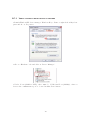
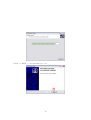
P ROGRAMMING
INTERFACE
The control device possesses also a special connector to be used for firmware upgrade.
Indeed, this special port, accessible by removing the front lid (see appendix C.2 for more
details), allows technical user to upload firmware by using an appropriate programmer. The
figure 3.3 gives the pinning of the port in details.
3
LED: Light Emitting Diode
15/ 93
GlucoBox System
LPM - EPFL
1
2
3
4
(1) N.C
(2) PGC
(3) PGD
5
6
(4) GND
(5) VDD
(6) MCLR
Figure 3.3: details of programming connector
3.2
C OMPUTER INTERFACE
The GlucoBox program communicates with the control device to download data stored in it.
A graphic shows the evolution of the glucose rate during the acquisition period. The software
gives also the possibility to set up some parameters of the GlucoBox.
3.2.1
RUNNING
THE INTERFACE
The interface is an self-executable running on Windows. The required specifications for using
this application are presented in the appendix B. Before launching this application, the
GlucoBox must be connected via USB, or else an error dialog box will appear.
3.2.2
U SING
THE INTERFACE
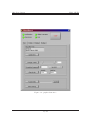
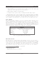
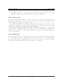
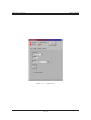
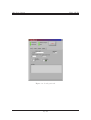
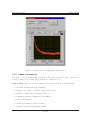
The interface shown in figure 3.4 contains four tabs:
• User: The user sees the time and date of the GlucoBox, can manage data (acquisition,
storage and erasing) and change parameters (date and time, alarm volume, automatic
acquisition frequency and alarm glucose level).
• Config: It is necessary to configure the communication (COM port selection and baud
rate choose) before to initiate it. The path for data storage can also be fixed.
• Display: A graphic is proposed to show the glucose level evolution. The user can choose
to display either the current acquired data, or import data previously acquired.
• Debug: This tab is reserved for developers only.
16/ 93
GlucoBox System
LPM - EPFL
Figure 3.4: graphical interface
17/ 93
GlucoBox System
LPM - EPFL
4 C ONTROL
DEVICE
Contents
4.1
4.2
4.3
4.4
4.5
Architecture . . . . . . . . . . . . . . . . . . . . . . . . . . . . . . .
Embedded peripherals . . . . . . . . . . . . . . . . . . . . . . . . .
19
20
4.2.1
4.2.2
Non-volatile memory . . . . . . . . . . . . . . . . . . . . . . . . . . .
USB transceiver . . . . . . . . . . . . . . . . . . . . . . . . . . . . .
20
22
4.2.3
4.2.4
Time management . . . . . . . . . . . . . . . . . . . . . . . . . . . .
Display . . . . . . . . . . . . . . . . . . . . . . . . . . . . . . . . . .
23
24
4.2.5 Alarm . . . . . . . . . . . . . . . . . . . . . . . . . . . . . . . . . . .
Wireless communication . . . . . . . . . . . . . . . . . . . . . . . .
25
25
4.3.1
4.3.2
MICRF506 overview . . . . . . . . . . . . . . . . . . . . . . . . . . .
Implementation of a RF protocol . . . . . . . . . . . . . . . . . . . .
25
27
4.3.3
Software implementation
. . . . . . . . . . . . . . . . . . . . . . . .
29
Power supply . . . . . . . . . . . . . . . . . . . . . . . . . . . . . . .
4.4.1 Accumulator . . . . . . . . . . . . . . . . . . . . . . . . . . . . . . .
30
30
4.4.2
4.4.3
Voltage regulator . . . . . . . . . . . . . . . . . . . . . . . . . . . . .
Power management . . . . . . . . . . . . . . . . . . . . . . . . . . . .
30
30
Embedded software . . . . . . . . . . . . . . . . . . . . . . . . . . .
4.5.1 Main . . . . . . . . . . . . . . . . . . . . . . . . . . . . . . . . . . . .
31
31
4.5.2
4.5.3
User task . . . . . . . . . . . . . . . . . . . . . . . . . . . . . . . . .
Storage task . . . . . . . . . . . . . . . . . . . . . . . . . . . . . . . .
31
31
4.5.4
4.5.5
Display task . . . . . . . . . . . . . . . . . . . . . . . . . . . . . . . .
Energy task . . . . . . . . . . . . . . . . . . . . . . . . . . . . . . . .
32
32
In order to achieve the functional requirements of the control unit, the corresponding
components for each task need to be wisely selected. A wide range of components exists, but
our selection is based on two main criteria: size and availability. The main reason is that these
criteria allow us to rapidly validate our concept. Although these parts may not necessarily be
the optimal ones, they shall fit in our demonstrator application. The next paragraphs depict
in details the characteristics of each part.
18/ 93
GlucoBox System
4.1
LPM - EPFL
A RCHITECTURE
One of the important factors when choosing an architecture is to decide which MCU1 is the
most suitable. On the market, there are a large number of MCU, some are dedicated or
optimized for special task. After the MCU has been selected, the peripherals2 – in the form
of an IC3 – must be chosen according to type of interface available on the MCU.
For the MCU, the dsPIC30F4011 [5] has been chosen for several reasons:
• It is readily available.
• It exists in small package form.
• This MCU is commonly used in the LPM laboratory (in fact, the actual bio-sensor
is built with this MCU !) and hence all hardware and software tools are immediately
available; another non-negligible aspect is that, at the LPM, there is a good background
on this MCU.
• By using the same MCU as in the bio-sensor, code portability and integration are easier.
• The MCU has enough IO4 lines and modules5 required in our application.
Another important feature of the dsPIC30F4011 is that it incorporates an internal oscillator: the latter can be configured to deliver sufficient computing power with a good comprise
on power consumption. Furthermore, it can operate at 3.3 V, which is a common voltage for
low power devices.
The next step is to choose the peripherals compatible with the MCU and 3.3 V. Moreover, the SPI6 has been chosen as interface with the peripherals for its ease of use and its
performance.
In order to achieve functional requirements of our project, the following peripherals are
necessary:
• a display with back-light,
• a time-management circuit to assign time stamp to each measurement and to allow
scheduling of readings,
• a non-volatile memory to store measured values (with a time stamp),
• a USB to UART7 transceiver to allow communication between the MCU and a PC via
USB.
1
MCU: Main Control Unit; in our case, it is a micro-controller
special device that is generally dedicated to a special task, for example, a non-volatile memory
3
IC: Integrated Circuit
4
IO: Input/Output
5
a special dedicated part of the MCU which accomplishes a special task, for example, the UART module
6
SPI: Serial Peripheral Interface; a trademark of Motorola, Inc.
7
UART: Universal Asynchronous Receiver Transmitter
2
19/ 93
GlucoBox System
LPM - EPFL
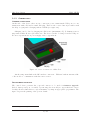
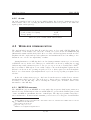
In addition to peripherals, power supply circuits must chosen to meet power requirements
of all components. Finally, the architecture is illustrated in figure 4.1. Each component is
discussed in the next paragraphs.
sound
alarm
buttons
Power
managment
MCU
UART
dsPIC30F4011
USB to UART
transceiver
USB
SPI
Time
management
RF transceiver
Non-volatile
memory
Display
Figure 4.1: hardware architecture of GlucoBox Control Device
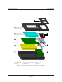
4.2
E MBEDDED PERIPHERALS
In this section, the characteristics, the hardware and software integration of the specific IC
are explained.
4.2.1
N ON - VOLATILE
MEMORY
The data must be stored in a non-volatile memory to avoid loosing them in case of power
loss. The size of this memory must be at least 150 kbytes, according to following equations.
memory size = (data size) × (number of data)
data size = (timeStamp size) + (measurement size)
number of data = (acquisition period) × (acquisition frequency)
with
timeStamp size = 7 bytes8
measurement size = 4 bytes
acquisition period = 3 months = 90 days
acquisition frequency = 6 per hour = 144 per day
⇒ memory size = (7 + 4) × (90 × 144) = 142560 bytes
8
1 byte for each: hour, minute, second, day, date, month, year
20/ 93
GlucoBox System
LPM - EPFL
The space required cannot fit into the MCU user memory (type is usually EEPROM9 ).
Hence, an external memory with sufficient capacity is required. A serial flash-memory has
been chosen as it requires few IO lines and it has a tiny package form. It fits all the requirements and standard models available have large capacities, allowing longer acquisition
periods. The characteristics of the IC used are listed in table 4.1.
NON-VOLATILE MEMORY
Reference
M45PE80VMP [6] from ST
Type
Flash
Memory size
1 Mbyte (8 Mbits)
Interface
SPI
Voltage
2.7 to 3.6 V
Standby current
50 µA
Packaging
VDFPN8
Dimensions
6 x 5 mm
Table 4.1: flash-memory characteristics
H ARDWARE
Electrical connections required is quite simple, as shown in appendix E.3.
S OFTWARE
The memory is organized in 16 sectors, each containing 256 pages which are 256 bytes-wide.
In current use, the first sector is reserved for GlucoBox special parameters. These values are
loaded after a reset. The rest of the memory (15 sectors) can handle up to 85’000 measurements (including time stamp) in the current implementation.
Modifying data can be done by two ways:
• Write data: It is the more usual way to modify data. The PW10 instruction provides
a convenient way of modifying data and simply requires the start address and the new
data in the instruction sequence. This instruction takes typically 11 ms.
• Program data: The PP11 instruction provides a fast (typically 1.2 ms) way of modifying
data, provided that it only involves resetting bits to 0 that had previously been set to
1 (after a PE12 instruction for example).
In current implementation, a total erasing (with PE instructions) is done before that the
measurements are stored. This erasing ensures that no overwriting occurs and that all bits
are set to 1. It provides the use of PP for measurements storage, which is faster than PW.
9
EEPROM: Electrically Erasable Read Only Memory
PW: Page Write
11
PP: Page Program
12
PE: Page Erase
10
21/ 93
GlucoBox System
LPM - EPFL
However, PW is used for the special parameters (first sector), because these data are continuously overwritten without PE instruction being done between two PW instructions.
It is important to note that if memory is full, all subsequent storage of readings is ignored.
In this case, patient is informed by an icon on the display.
4.2.2
USB
TRANSCEIVER
As the chosen MCU does not have a USB module, an external transceiver in needed to
communicate with a PC. For this purpose, specialized IC are available on the market, the
most common of them is the FT232B [7] from FTDI. The main advantages of using this IC
is its maturity and the complete software support from the manufacturer. The connection on
the host PC can be implemented in two ways: as a serial communication port or a normal
USB port (both drivers are available for different OS). The first method is simpler for the
software development on the host PC. Moreover, a high transfer rate is not necessary for our
application. The characteristics of the FT232B are summarized in table 4.2.
USB TO UART TRANSCEIVER
Reference
FT232BQ
Interface
UART & USB
IO voltage
3.0 to 3.6 V
Suspend current
200 µA
Package
QFN32
Dimensions
5 x 5 mm
Table 4.2: USB transceiver characteristics
H ARDWARE
No particular components are required to use the FT232B (refer to appendix E.6), except
that care must be taken regarding to the precision of the crystal (see datasheet for more
details). An interesting feature of the FT232B is that it can be powered from the USB cable,
thus the IC operates only a USB connection is present. This simplify power saving scheme
implementation.
S OFTWARE
As mentioned before, the FT232B is used a serial communication port13 on the host PC.
Hence, the FT232B is transparent to the communication between MCU and host PC. Indeed,
for the PC, the MCU is a simple data terminal equipment. On the other hand, the MCU can
communicate directly to the PC by simply sending data using its UART module.
13
in fact, this port is a virtual port as host program thinks it is a usual communication port; this abstraction
from the real port is provided by installed drivers
22/ 93
GlucoBox System
4.2.3
T IME
LPM - EPFL
MANAGEMENT
The date and time must be known for time stamping measurements and for patient general
information. A software implementation on the MCU can be done, but it will constantly
need processor resources, preventing the MCU to enter power saving mode. A more efficient
way to save energy is to use an external device for time-keeping (it usually consumes much
less energy than the MCU; this is the role of a RTC 14 . In our application, a RTC with
its own power management is required. Nowadays, this criterion is commonly implemented.
However, more features like programmable wake up, electrical interface, size and availability
restricted our choice. The DS1305 [8] from MAXIM has been chosen for its characteristics,
namely those shown in table 4.3.
RTC
Reference
Interface
Time resolution
Power management
Voltage
Timekeeping current
Package
Dimensions
DS1305E
SPI
seconds
auto-select from primary or backup source
2.0 to 5.5 V
1 µA
TSSOP-20
6.4 x 4.4 mm
Table 4.3: RTC characteristics
H ARDWARE
This IC needs a precise 32.768 kHz crystal (refer to datasheet for more information). The
RTC will use primary source to power itself (GlucoBox being generally powered at all time).
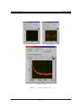
Nevertheless, in case on main power loss, a backup battery, in the form of a large value capacitor (0.2 F) is required to keep the RTC working. This type of source is very compact and
can provide sufficient energy for about a week, according to equation 4.1, which is sufficient
for our application. Calculations are based on [9]. Electrical implementation is provided in
appendix E.3.
!
Vbackup|min
Vbackup|min
× Capacitor
×
time = − ln
Vbackup|max
Ibackup|max
1.3
3.3
= − ln
× −6 × 0.2
3.3
10
≈ 6000 000 s ≈ 167 h ≈ 7 days
(4.1)
S OFTWARE
The RTC can be configured by accessing special registers in the IC via the SPI interface. To
setup up the RTC, the following steps are made:
14
RTC: real-time clock
23/ 93
GlucoBox System
LPM - EPFL
• When the RTC is powered to the first time, the oscillator is locked. The oscillator will
run after the control register has been correctly written to.
• Enable alarm by writing to the status register.
• Configure the super capacitor charge by writing in the trickle charger register.
Time information can be read at any time in the corresponding registers of the RTC.
The format used is specific and is not suitable as a time stamp. A function that converts
to readable format has been implemented. The time stamp is then represented by a set of 7
bytes containing corresponding values of year, month, day, date, hour, minute and second.
4.2.4
D ISPLAY
The measurement must be displayed on a screen to inform the patient of his glucose level.
A large dot-matrix LCD15 module (including driver) has been chosen, to allow further enhancements (glucose level trend on a graphic on GlucoBox). Its characteristics are shown in
table 4.4. For integration of the backlight, the IC named SP4422A from SIPEX16 has been
withdrawn from its based module PSEL-22 [10] provided by Electronic Assembly and placed
directly on the hardware design. For more details, refer to appendix E.4
Display reference
Driver reference
Interface
Resolution
Display size
Voltage
Sleep current
DISPLAY
W128A-6X9HEW [11] from Electronic Assembly
S6B1713 [12] from Samsung Electonics
SPI or parallel
128 x 64 pixels
52 x 33.5 mm
2.4 to 3.6 V
100 µA
Table 4.4: graphical LCD module characteristics
D ISPLAYING
A PICTURE
The main drawback of graphical display is that displaying a text is not easy. As a matter of
fact, the characters are represented by pictures and each bit of the picture must be correctly
located on the screen. The data displayed are transfered from the MCU to the DDRAM17
of the display driver via the SPI interface. The data are mapped in a 65-row by 132-column
array, addressable via page and column selection (for more details, refer to the datasheet).
To load picture into the DDRAM, see appendix F.
15
LCD: Liquid Cristal Display
http://www.sipex.com
17
DDRAM: Display Data Random Access Memory
16
24/ 93
GlucoBox System
4.2.5
LPM - EPFL
A LARM
An audio transducer has been chosen for audible alarm. Its electrical consumption is lower
than a buzzer. Moreover, by using the MCU PWM18 module it is possible to modulate the
signal (volume and frequency).
Reference
Sound pressure level (min)
Voltage (max)
ALARM
PKM13EPY-4000-A0 [13] from Murata
70 dB
30 Vp-p
Table 4.5: piezo-ceramic alarm characteristics
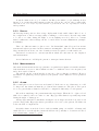
4.3
W IRELESS COMMUNICATION
The wireless link between the GlucoBox and the sensor is done with a RF IC. Many IC’s
are available on the market, but only some of them can operate in the 433 MHZ ISM [14]
(Industrial Scientific and Medical) band. Moreover, IC for medical applications such as active
implants, should comply with special regulations19 and manufacturers are less willing to face
lawsuit in case of device incompatibility or failure.
An implementation of a RF chip has been done during a summer semester project citeremy
at LPM laboratory. At the end of this project, an IC has been chosen by taking into account
different important parameters (refer to the project report for more details) and a PCB20
has been realized. Although it does not fully comply to the medical implant regulations, the
IC has been chosen as its operating frequency is close to that required for medical implant.
Indeed, for a demonstrator (an implant has not yet been developed), this prerequisite is not
absolute.
At the end of this semester project, only basic electrical tests were realized but no software
implementation had been done. The next step to this work is to implement the software
necessary to use the RF chip. Before entering the software part, we must consider basic
information of the RF chip.
4.3.1
MICRF506
OVERVIEW
The MICRF506 [15] from MICREL is a true single-chip frequency shift keying transceiver
intended for use in half-duplex, bidirectional RF links. It operates in the ISM frequency band
of 410 - 450 MHz at a maximum data rate of 200 kbps21 . The chip is programmed via a threewire serial interface. Features include transmit power selection, low energy modes and RSSI22 .
18
PWM: Power Width Modulation
402-405 MHz frequency band; ITU-T Recommendation SA 1346, US FCC rules CFR47 Part 95.628 and
Europe’s ETSI Standard EN301839
20
PCB: Printed Circuit Board
21
kbps: kilo bits per second
22
RSSI: Received Signal Strength Indicator
19
25/ 93
GlucoBox System
LPM - EPFL
The design of this transceiver is based on the reference design supplied by MICREL.
General configuration of the MICRF506 in our application is summarized below:
• 433 MHz operating frequency
• VCO modulation at 38.462 kbps
• Manchester encoding
23
• RSSI enabled
Manchester encoding [16] has been used as it does not add much overhead. This type of
coding is recommended by MICREL but other types of coding may also be used.
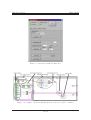
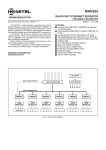
Interface with MICRF506 is done with the help of 8 lines, as shown in figure 4.2. Description of each line is given below.
CS
Antenna
MICRF506
SCLK
IO
DATAIXO
DATACLK
LD
RSSI
Programming
interface
Data
interface
Status lines
Figure 4.2: electrical interface of MICRF506
Programming interface. The MICRF506 functions are enabled through a number of programming bits. The programming bits are organized as s set of addressable control registers,
each register holding 8 bits. The control registers are accessed through a 3-wire interface;
clock (input), data (bi-directional) and chip select (input). These lines are referred to as
SCLK, IO and CS, respectively.
Data interface. The data interface consists of a clock (output as it is provided by MICRF506) and a bi-directional data. These lines are referred to as DATACLK and DATAIXO,
respectively. The data interface is defined in such a way that all user action should take place
on falling edge of DATACLK.
Other lines. Two more lines (outputs) are provided more information about the IC: a lockdetect pin (LD) indicates that the PLL24 is locked and a RSSI analog pin gives the strength
of the RF signal.
23
24
0 is represented by a 0↑1 transition and 1 by a 1↓0 transition
PLL: phase lock-loop, more details in datasheet
26/ 93
GlucoBox System
LPM - EPFL
Antenna. Through this essential component, the transceiver will emit and receive RF signals. Main characteristics are impedance and gain. Antenna can be found in various forms,
each with its advantages and drawbacks. Making antennas is itself a field of study. In our
application, antenna performance is not critical (a range of only a few meters are required).
However, antenna dimension is the main factor to chose the right one. In this context, a
compact SMD25 multilayer ceramic antenna has been chosen [17].
An important note is that MICRF506 works at 2.5 V where as the MCU operates at 3.3 V.
Hence, levels must be adequately translated to enable correct electrical interface between these
two parts. This is done by specialized circuits exist which allow bi-directional communication.
An example of such circuits is the MAX3001E [18] from MAXIM.
For more details of electrical implementation, refer to appendix E.5.
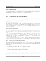
4.3.2
I MPLEMENTATION
OF A
RF
PROTOCOL
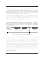
Data exchange through MICRF506 is done using a bidirectional data line. A RF protocol
needs to be built in order to give a meaning to data other than a series of bits. For this
purpose, a multilayer protocol has been developed. Figure 4.3 depicts the different layers
that compose the RF protocol.
Application
- Send and receive data
- Assign power mode
Transport
- Configuration
- User data
- Packet structure
Data link
Physical layer
- Sampling data line
- Output on data line
MICRF506
HOST
TRANSCEIVER
Figure 4.3: description of protocol for MICRF506
In the host part contains two layers: the Data link is responsible for interfacing with the
MICRF506 via dedicated electrical lines and the Transport layer handles data at a higher
level. Indeed, this layer is an essential part of the protocol as it ensures correct translation
of low level data and hands it over to user application. Furthermore, the Transport layer
provides primitives to access the transceiver. Finally, in the user application, several routines
are available to easily exchange data over RF and control running state of the transceiver.
This implementation is quite common to a wide range of protocols. Indeed, protocols are
structured in layers in order to give higher level of abstraction on upper layers. Each layer can
be considered as a black-box with inputs and outputs. If a black-box must be modified, it does
not affect upper nor lower layers (it is obvious that inputs and outputs must not be altered).
A typical example is the Data link which is implemented according to the transceiver and
host employed; if another transceiver is used, only the Data link is to be reprogrammed.
25
SMD: Surface Mounted Device
27/ 93
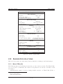
GlucoBox System
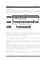
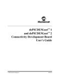
F RAME
LPM - EPFL
STRUCTURE
Packets sent over RF are divided into blocks, as shown in figure 4.4. In our case, a maximum
of 20 bytes are sent per packet (in reality, due to Manchester encoding overhead, twice that
number of bytes are sent). The roles of each block are explained below.
11 to 20 bytes
Frame level 1
Preamble
3
Sync
Length
1
Payload level 1
1
6 - 15
CRC 16 computation source
Frame level 2
Payload level 2
1 - 10
Sender’s ID
1
Frame level 3
Sender’s address
Recipient’s address
1
1
Payload level 3
0- 9
CRC value
2
Frame type
1
Figure 4.4: structure of the frame – values indicate size in bytes
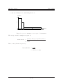
Preamble. At the beginning of a received data packet, the bit synchronizer clock frequency
is not synchronized to the bit rate. The equivalent time of a minimum number of 22 bits are
required before synchronization is achieved. In our application, more bits are used so that
receiver in search mode can sample correctly RSSI level.
Sync. Data received is merely a bit stream without start nor end parts. This byte allows
receiver to identify where is the start of the packet.
Length. This byte is necessary to inform receiver how many bits is expected in the packet.
The value must be in the allowed range of frame structure (6 to 15) or else, rest of packet is
ignored.
Sender’s ID and Address. The sender has two parameters which help to identify it. Its
identification (ID) is a value that represents the class of equipment to which it belongs (at
this stage only one ID is used, other values will be allocated in the future) and its address
must be unique in each class of equipment. Receiver is programmed to respond to only a
specific class ID and to one sender (address) at a time.
Recipient’s Address. This value is verified by receiver to check to whom the packet is
intended. In this case of address match with its own address, receiver will undertake action.
28/ 93
GlucoBox System
LPM - EPFL
CRC Value. Integrity of packet must be verified to ensure that data it contains are correct.
A CRC26 computation is a common way to validate data integrity. Implementation used is
based on the CCITT27 algorithm. The 16-bit version is used [19]. More information can be
found on the Internet, a good start is [20].
Frame type. The final payload extracted is called Payload Level 2. It includes a field that
designates the type of the frame. It allows custom commands to be simply implemented here
and extra data can be put in the rest of the payload (Payload Level 3 ).
In our case, the values given are sufficient to realize required tasks in a Master – Slave
configuration (the master being the GlucoBox and the slave is the remote sensor). The size
of each part can be easily modified to fit other applications. Moreover, the frame structure
provides a flexible framework to implement more complex networks (multi-master, routing,
broadcasting, etc.).
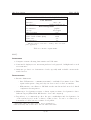
4.3.3
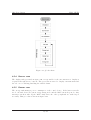
S OFTWARE
IMPLEMENTATION
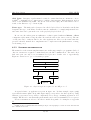
The main idea of the software implementation is to make usage simple to programmer. Indeed,
only few routines are required to immediately use the RF communication. The trade-off is
that some part can only be set at firmware level (for more details, refer to appendix G).
Figure 4.5 shows how to proceed in main program.
Initialization
Set local parameters
Set RF mode
Transmit packet
Receive packet
Toggle mode
Figure 4.5: only few steps are required to use RF protocol
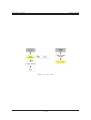
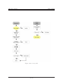
A typical scheme on application is given in figure 4.6. In this example, figure 4.6(a)
represents the master (GlucoBox) while figure 4.6(b) corresponds to the slave (sensor). Using
different power states, it is possible to implement a low energy consuming application. For
example, RF IC can be automatically put in standby mode after a transmission of a reception.
For more information on how to use these routines along with code examples, see appendix
G.
26
CRC: Cyclic Redundancy Check
CCITT: Comité Consultatif International Téléphonique et Télégraphique, now known as the International
Telecommunication Union
27
29/ 93
GlucoBox System
LPM - EPFL
initiate
communication
S end
packet
initiate
communication
idle
Data
received
Wait for
response
E xtract data
Check
RS S I
idle
no signal
signal
present
Receiv e
packet
timeout
Re-send
packet
E rror
Retry
counter -counter = 0
S end
packet
Take
measurement
counter > 0
(a) master state machine
(b) slave state machine
Figure 4.6: examples of use of RF protocol
4.4
P OWER SUPPLY
The power scheme (figure 4.7) can be divided into three items: portable electrical accumulator,
power supply regulation and power manager for external electrical energy source.
external
source
regulator
power
manager
accumulator
system
Figure 4.7: energy flow in the device
4.4.1
ACCUMULATOR
A Lithium-polymer type battery has been chosen to provide sufficient energy to our system.
This type of battery has superior capacity compared to other types of batteries with same
size and weight. Moreover, it can easily be found in compact slim form. The model used is
for our system is a 1500 mAh running at 3.7 V from Kokam [21]. It fits our enclosure and
has sufficient capacity to power our system for a minimum period of time.
4.4.2
VOLTAGE
REGULATOR
Our system requires two different voltages: 2.5 V for RF chip and 3.3 V for the rest. Moreover,
these voltages will be provided from the battery which is only at nominal 3.7 V. Hence a lowdropout regulator is necessary. An IC from Maxim [22] has all needed characteristics: in a
single compact package, the MAX8883 can deliver up to 160 mA on each voltage channel.
4.4.3
P OWER
MANAGEMENT
A dedicated IC exists that matches exactly our needs: it’s the bq24022 from Texas Instruments
[23]. It has the capability of handling two sources for charging Lithium-polymer batteries (or
30/ 93
GlucoBox System
LPM - EPFL
Lithium-Ion). Indeed, it can automatically select the USB port or the AC adapter as the
power source for the system. In the USB configuration, the host can select from two preset
charge rates of 100 mA and 500 mA. In the AC adapter configuration, an external resistor
sets the magnitude of the charge current. This IC has been chosen for its functionalities,
compactness and simplicity of implementation.
When using the bq24022, a suitable external AC adapter is a 6 V with a minimum of 1
A output. In our case, current drained from USB port has been limited to 100 mA.
4.5
E MBEDDED SOFTWARE
The software embedded on the GlucoBox has been programmed in C language and compiled
with a dsPIC version of gcc: C30 (see appendix C.1). The MPLAB IDE v7.22 has been used
for its development. Source code files are available on installation CD, see appendix H.
4.5.1
M AIN
The main function has two parts, they are shown in figure 4.8.
1. initialization: calls different initialization functions
2. infinite loop: calls four tasks sequentially
The user, storage and display return a value corresponding to its state (active or inactive).
This information is used by the energy task to manage power.
The current implementation allows a reboot (intentional or not) without much problem.
This is achieved by saving critical parameters (alarm scheduling, next storage address,...) on
the non volatile flash memory. Hence, even if the MCU is reseted, these parameters can
be loaded at any time. If an unexpected problem occurs, the user can simply reboot (reset
pin-hole) the control device to restore the system’s configuration.
4.5.2
U SER
TASK
The user task establishes the communication with the computer via the USB transceiver. If
there is a data transaction, an interrupt occurs and the command is executed. The command
with its data is received from the computer and the corresponding command is executed. The
principal components of this function are shown in figure 4.9. The different commands will
be explained in the chapter 5 (which describes the PC software).
4.5.3
S TORAGE
TASK
The storage task is responsible for automatically acquiring measurement and storage. Most
of the time, the MCU is in sleep mode and is waked up by the RTC alarm; this triggers a
communication with the sensor and fetch data. The figure 4.10 shows this task in details.
31/ 93
GlucoBox System
LPM - EPFL
Figure 4.8: global scheme
4.5.4
D ISPLAY
TASK
The display task, presented in figure 4.11, is responsible for the user interaction: display is
requested through the two buttons. The green button is used to display a measurement and
the red one for enabling/disabling the audible alarm.
4.5.5
E NERGY
TASK
The energy task manages power consumption of the control device. If the latter is in idle
mode, external devices are put in energy saving mode and the MCU enters sleep mode. Any
interrupt can then wake up the MCU. Only then, the other peripherals are waked up if
necessary. This procedure is shown in figure 4.12.
32/ 93
GlucoBox System
LPM - EPFL
Figure 4.9: user task
33/ 93
GlucoBox System
LPM - EPFL
Figure 4.10: storage task
34/ 93
GlucoBox System
LPM - EPFL
Figure 4.11: display task
Figure 4.12: energy task
35/ 93
GlucoBox System
LPM - EPFL
5 S OFTWARE
Contents
5.1
5.2
Programming environment: Labview . . . . . . . . . . . . . . . . .
Functionalities . . . . . . . . . . . . . . . . . . . . . . . . . . . . . .
36
36
5.2.1
5.2.2
Config tab . . . . . . . . . . . . . . . . . . . . . . . . . . . . . . . . .
User tab . . . . . . . . . . . . . . . . . . . . . . . . . . . . . . . . . .
36
37
5.2.3
5.2.4
Display tab . . . . . . . . . . . . . . . . . . . . . . . . . . . . . . . .
Debug tab . . . . . . . . . . . . . . . . . . . . . . . . . . . . . . . . .
38
38
The GlucoBox software running on the computer is a graphical user interface giving the
possibility to manage data (acquisition, storage, graphic display and export) and parameters
from the Glucobox. The goal of this software is to quickly show the capability of the control
device.
5.1
P ROGRAMMING ENVIRONMENT: L ABVIEW
Labview R 1 has been chosen as it allows rapid development of complex program. It contains
a lot of functions for data acquisition, file management and other useful features. Indeed,
Labview has built-in serial functions, which allow easy communication with the serial device.
The final application has an attractive visual interface.
5.2
F UNCTIONALITIES
The functionalities are available for the user through four tabs with different usage. Four LEDs
give information about the state of the program, they are described below in corresponding
sections. The main components of the program are shown in figure 5.1.
5.2.1
C ONFIG
TAB
This fields of this tab, shown in figure 5.2, must be filled in correctly before beginning the
communication with the GlucoBox control device:
1. The correct port, through which the control device is connected must be selected (generally noted as ASRLX::INSTR, where X corresponds to the number of the COM port;
please refer to appendix B.7.2 for driver installation).
1
This product from National Instrument (http://www.ni.com/) is a graphical programming environment
to build data acquisition and instrument control applications.
36/ 93
GlucoBox System
LPM - EPFL
2. The baudrate correspond to the connection speed. It can be changed by the user but
must be compatible with the configuration of the MCU. On current implementation,
the chosen baudrate is 476 kbits per second.
3. The program gather data and store them in the user-defined save path. This path must
be valid prior to saving data.
After all theses fields have been correctly filled in, the configuration button must be activated, and only then functionalities may be used. The configuration LED toggles from red
to green to confirm that the configuration has been done. The configuration parameters are
fixed as long as the program is running. To change parameters, the user must first stop the
application with the corresponding button.
The transmission enable check must be set for data transfer; the corresponding LED shows
its state. In case of communication failure, this check can be disabled then re-enabled, to
restore the communication.
5.2.2
U SER
TAB
When the configuration is done and the transmission enable, the user can interact with the
control device. The interaction This tab contains three parts, shown in figure 5.3:
1. Time management: If no other functionality is used, the program automatically request
the GlucoBox date and time every 100 ms. The user can also update the time if it is
wrong (due to too long inactivity period for example).
2. Parameters setting: The acquisition frequency, alarm volume and the two glucose level
thresholds can be set separately.
3. Data management: The data acquired by the GlucoBox can be download and stored in
the computer. The download time depends of the volume of data to transfer, a progress
bar informs the user of the transfer state. An abort button is also available. All the
data stored in the GlucoBox can be erased if the corresponding button is activated.
The raw data acquired are saved with the date as name (example 23-02-06.gbx). Note
that the *.gbx extension has been created for this application. Data are simply 8-bits values.
E XAMPLE :
TIME UPDATE PROCEDURE
All commands are implemented in the same way. An example of the time update command
is described below. The figure 5.4 shows how this command is implemented in Labview.
1. The user activates the update time button.
2. Labview sends the corresponding command (1 byte) with the date and time (7 bytes)
via the serial port.
3. The GlucoBox MCU receives the command through its interruption routine. The MCU
interprets this command and excepts 7 more bytes data. When all the bytes have been
received, it stores them in a buffer.
37/ 93
GlucoBox System
LPM - EPFL
4. The MCU executes the corresponding part of user task: reads the buffer, converts date
and time to RTC compatible format and write them to the RTC.
5.2.3
D ISPLAY
TAB
In this tab, a graphic shows the glucose level evolutions. The development of this XY display
is relatively easy thanks to Labview built-in plot modules. Some tools are available for the
user, to manage the graphic (zooming, moving, ...).
In current implementation, when the display button is activated, a export file is automatically created. This *.csv file (example 23-02-06.csv), containing the data in a adequate
format, can be directly opened in Excel for further analysis.
Displaying the graphic may take some time, depending on the number of data; during
this period, the communication is lost: the display in progress LED turns red. The figure 5.5
represents three screenshots of the display: initial view, with a plot of acquired data and a
zoom on a special zone.
5.2.4
D EBUG
TAB
This tab, shown in figure 5.6, is intended to developers only and is used to test and validate
new commands between the computer software and the control device. The command are
sent as the same way as commands available in the user tab. Data received from the MCU
are displayed in different format (byte array, string, boolean array).
38/ 93
GlucoBox System
LPM - EPFL
Figure 5.1: flowchart of GlucoBox Software
39/ 93
GlucoBox System
LPM - EPFL
Figure 5.2: configuration
40/ 93
GlucoBox System
LPM - EPFL
Figure 5.3: interaction with the GlucoBox
Figure 5.4: example of Labview implementation of the time update command
41/ 93
GlucoBox System
LPM - EPFL
(a) before plot
(b) after plot
(c) after zooming
Figure 5.5: graphic display steps
42/ 93
GlucoBox System
LPM - EPFL
Figure 5.6: developer’s tab
43/ 93
GlucoBox System
6 H ARDWARE
LPM - EPFL
DESIGN
Contents
6.1
6.2
Mechanical . . . . . . . . . . . . . . . . . . . . . . . . . . . . . . . .
PCB layout . . . . . . . . . . . . . . . . . . . . . . . . . . . . . . . .
44
44
Once all the components have been selected, the design can start. There are two main
aspects:
• Mechanical. Main constraints are placement of components which are visible from
outside of the case. In doing so, the size and the form the PCB will be defined.
• Electrical. Once the dimensions of the PCB are defined, the layout of all electrical
components can be made.
It can be noted that the first part can be refined if additional constraints are revealed in
the second part. For this reason, this approach is not strict and backward re-definitions may
be necessary.
6.1
M ECHANICAL
A common ABS plastic case has been chosen to contain all components. We have taken
advantage of the presence of the battery room to fit all necessary connections, namely the
programming connector. Hence, the latter can be easily accessed by simply removing the lid.
Figure 6.1 shows in details on how all the mechanical parts are assembled in the GlucoBox.
However, this accommodation of the connectors imposed the use of two separate PCB (referred
to as main board and daughter board). Each of them was defined by the maximum place
available in the assemblage and are interconnected through a multi-way flat cable.
6.2
PCB LAYOUT
Before designing a PCB, it is obvious that all necessary components should be known. For
this purpose, each device has been tested on prototype boards to evaluate them. Then, all
values of each component were assigned.
The first step when designing a PCB is to know which technology will be used. In our case,
standard rigid epoxy board, 0.8mm thick for two layers has been chosen. The main reasons
for this choice is that the PCB can be realized quickly (at ACI workshop1 of the EPFL)
1
http://sti-ateliers.epfl.ch/page8438.html
44/ 93
GlucoBox System
LPM - EPFL
and a two layer-design can be easily analyzed for errors. However, a two-layer design is not
optimal in a mixed analog/digital configuration. Thus, special precautions must be taken
[24]. Moreover, general fabrication rules must be respected (they are given by workshop).
Main constraints associated with the GlucoBox architecture are listed below:
• RF part as far as possible from digital part.
• RF components as close as possible to MICRF506.
• Largest ground plane on the bottom layer (except below the antenna).
• Two separate power planes on top layer.
• No parts or signal below RTC crystal.
• Tracks as short as possible for analog signals.
• LCD connector on the bottom layer.
• Include fixation holes.
• Two PCB – main board and daughter board – connected through a multi-way cable.
It should be noted that all components are all SMD-type, except for buzzer and headers.
After taking into account all the rules, the two PCB have been designed, they are shown in
the following figures. All schematics can be found in appendix E.
45/ 93
GlucoBox System
LPM - EPFL
(1) base
(2) daughter PCB
(3) battery
(4) main board PCB
(5) support for push-buttons
(6) push-buttons
(7) LCD display
(8) top cover
(9) top lid
Figure 6.1: mechanical parts used in GlucoBox assembly
46/ 93
GlucoBox System
(1)
(2)
(3)
(4)
(5)
(6)
LPM - EPFL
MCU: dsPIC30F4011ML
USB to UART transceiver: FT232BQ
RTC: DS1305E
Non-volatile memory: M45PE80VMP
RF transceiver: MICRF506BML
Level translator: MAX3001E
(7) Power management IC: bq24022DRC
(8) Voltage regulator: MAX8883EUTAQ
(9) Piezoelectric sound transducer
(10) Multilayer ceramic SMD antenna
(11) Connector to daughter board
(12) Voltage inverter: SP4422A
Figure 6.2: top view of the main board
47/ 93
GlucoBox System
LPM - EPFL
(1) LCD connector
(2) Ground plane
Figure 6.3: bottom view of the main board
(1) DC connector
(2) Bridge rectifier
(3) Connector to main board
(4) USB connector
(5) Reset button
(6) Programming connector
Figure 6.4: top view of daughter board
48/ 93
GlucoBox System
LPM - EPFL
7 T ESTS
AND RESULTS
Contents
7.1
7.2
Test conditions . . . . . . . . . . . . . . . . . . . . . . . . . . . . . .
Results . . . . . . . . . . . . . . . . . . . . . . . . . . . . . . . . . . .
49
49
7.2.1
7.2.2
RF . . . . . . . . . . . . . . . . . . . . . . . . . . . . . . . . . . . . .
Gathering data and display in PC software . . . . . . . . . . . . . .
50
50
7.2.3
Power consumption . . . . . . . . . . . . . . . . . . . . . . . . . . . .
51
As we have seen before, the electrical part of our concept is predominant. Therefore, no
mechanical “tests” have been made. Electrical test is the first prerequisite for validating our
concept. For this purpose, each part of the architecture was tested separately, starting with
the power management.
Once all parts had been tested individually, the whole system has been subjected to
different tests.
7.1
T EST CONDITIONS
To validate our concept, a bio-sensor is required. Unfortunately, at the test phase of the
project, the bio-sensor was not available. In fact, the demonstrator bench module was ready
but no measurement was feasible. For this reason, the base module for the bio-sensor has
been modified to integrate a temperature sensor (for schematics, refer to appendix E.8 to
E.11). Furthermore, the RF part of the module had not yet been validated (as mentioned
before, no characterization was made at that time [25] ).
In this context, temperature values are fetched in place of glucose levels. The temperature
sensor has been programmed so that its response is similar to expected bio-sensor (1 s for
making a measurement and value sent is coded on 4 bytes). Moreover, the bio-sensor has
been programmed with an defined address and it responses only to a special command.
7.2
R ESULTS
Currently, all functional tasks are achieved, according to project requirements. However, one
main requirement has not been reached: RF range is less than expected 3 m, as described
below.
49/ 93
GlucoBox System
7.2.1
LPM - EPFL
RF
Based on the reference from MICREL does not always imply good RF performance. Indeed,
other factors, such as routing design, proximity of disturbance sources, quality of power supply and antenna, have great influence on RF performance. The PCB design have been made
by following basic rules, but no guarantee was to be expected, as stated by a RF specialist1 .
The recommendation was to design the PCB and then to evaluate RF performance. This
approach is comprehensible as no simulation for such designs can be performed, for lack of
electrical models. However, this does not mean that RF performance cannot be improved.
Unfortunately, RF improvements and specific tests (such as power loss and error rate) have
not been done due to lack of time and current knowledge. In spite of poor RF performance
(maximum range is 20 cm), the concept of the GlucoBox System has been validated, as
depicted in the following sections.
7.2.2
G ATHERING
DATA AND DISPLAY IN
PC
SOFTWARE
Figure 7.1 shows GlucoBox at work, displaying a requested temperature value (alarms set are
arbitrary temperatures). For test purposes, the room temperature was sampled by GlucoBox
(automatic sampling period of 2 minutes) for a period of 24 hours. At the end of this test,
data have been transfered to a PC using the GlucoBox software. A plot of this result is shown
in figure 7.2.
Figure 7.1: GlucoBox displaying a reading (1:1 scale)
1
Mr. Jean-François Zurcher from the LEMA laboratory at EPFL
50/ 93
GlucoBox System
LPM - EPFL
Figure 7.2: temperature plot using GlucoBox software
7.2.3
P OWER
CONSUMPTION
According to project requirements, at least a week of autonomy is need. Yet, a greater autonomy is achieved by current design, as shown by equations below.
Case of figure (values of current consumption are those measured on actual design):
• automatic measurement each 10 minutes,
• duration of a request: 6 s with no display (worst case),
• duration of display after a manual request: 5 s,
• 2 manual requests in each interval of 10 minutes,
• battery fully charged,
• current level during a request: 70 mA,
• current consuption during display: 40mA,
51/ 93
GlucoBox System
LPM - EPFL
• current consumption of 5 mA during idle mode,
Current [mA]
70
40
5
Time [s]
18
10
572
Figure 7.3: power consumption over a period of 10 minutes
The average current consumption is given by:
(3 × 6) × 70 + (2 × 5) × 40 + 572 × 5
600
≈ 8 mA
mean current =
Hence, battery lifetime is given by:
1500
8
= 187.5 h > 7 days
battery lifetime =
52/ 93
GlucoBox System
LPM - EPFL
8 C ONCLUSION
8.1
F UTURE WORK
As we have seen in the previous chapter, both hardware and software concepts of the GlucoBox
System have been validated. Nevertheless, some important aspects must be reviewed to
provide better reliability. These points are (in order of priority):
• RF transmission; sources of malfunction must be identified and corresponding measures
must be taken. This part is crucial as without it, the concept is no interest. In case
of failure, it is highly recommendable to move to another transceiver. The main reason
is that new IC on the market require less critical layout. Moreover, new functionalities
are directly implemented in the IC itself, enabling higher communication reliability.
• PC software; some unexpected errors have occurred during utilization and have to be
rapidly identified. Moreover, it desirable to have two versions for doctor and patient.
• Debugging of embedded software and optimize code for better performance.
• Integration; the first application GlucoBox System was to operate with a bio-sensor.
In this context, it is desirable to test the concept with real bio-sensor as quickly as
possible. In this part, the implementation of the RF protocol will also be validated on
the bio-sensor.
• Update hardware and software implementation in the MCU, according to manufacturer’s up to date information (at this time, not all parameters have been defined !).
• Measure more precisely power consumed by each part and optimize the system’s power
management.
• Whole system; add and improve functionalities for ease of use.
• Review PCB design for greater performance and to accommodate custom identification
used by FTDI IC (an external EEPROM is requires to store vendor information).
8.2
P ROJECT CONCLUSION
The initial goal of the project was to develop a simple device to communicate with a biosensor, for a demonstrator bench. But, our motivation grew up when we noted that our
project can, in a longer term, help people suffering from diabetes. GlucoBox System can be
considered as a concept for a future commercial product in the medical field.
This project is very ambitious. Indeed, our role was to build the foundation for the commercial product. In spite of having only few guidelines at the beginning of our project, we
53/ 93
GlucoBox System
LPM - EPFL
have been able to tackle a typical engineer problem from the beginning to the end. Finally,
we ended up with a functional concept in a relatively short period of time.
We hope that our project will be carried on and as a result, lead to the final product. In
this scope, some improvements are essential for a key success:
• Mechanical aspect; re-design the enclosure so that is can meet medical regulations. This
part will also be profitable to improve external look.
• Electrical; as for mechanical aspect, medical conformity is essential. One of the main
part here concerns the wireless link. New IC must be prospected in order to respect
medical regulations.
• PC software; portal to common OS, like MAC OSX or Linux.
• Global study: to reduce cost of development, a broader study should be performed. Currently, costs of components of GlucoBox control device are relatively high, around 300
CHF (details in D). New technologies, fabrication processes and assembly techniques
must be adequately chosen to achieve lower costs, thus making the system affordable
to diabetic patients.
Lausanne, February 24, 2006
Sadasing Kowlessur
54/ 93
Damien Perritaz
ACKNOWLEDGMENTS
During the realization of this project, we were kindly guided and helped by many persons.
We would like to thank these persons for their support and advice:
• Mr. Eric Meurville and Mr. Léandre Bolomey (both from the LPM laboratory), our
assistants for this project.
• Mr. Jean-François Zurcher (LEMA/EPFL) who kindly gave us practical advice on RF
designs.
• Mr. Corradini Giancarlo (LPM/EPFL) who helped us to mount our PCB components.
• Mrs. Irma Blanco (CHUV) for her precious information on glucometers and patients’
needs.
• Mr. Michel Tille (Electronitel SA) was our contact for MICREL parts.
• Mr. Julien Chassot (LPM/EPFL) for his encouragement us throughout the project.
• Mr. Valentin Longchamp and Samuel Progin (EPFL), our classmates, for their constructive remarks on our report.
55
L IST
OF
F IGURES
1.1
general concept of the control device . . . . . . . . . . . . . . . . . . . . . . .
2
2.1
2.2
2.3
commonly used monitor devices found on the Swiss market . . . . . . . . . .
custom-made concept (Sx: software development, Hx: hardware development)
concept based on an existing host (Sx: software development, Hx: hardware
development) . . . . . . . . . . . . . . . . . . . . . . . . . . . . . . . . . . . .
5
12
3.1
3.2
3.3
3.4
GlucoBox dimensions in mm . .
view of connectors of GlucoBox .
details of programming connector
graphical interface . . . . . . . .
.
.
.
.
.
.
.
.
.
.
.
.
.
.
.
.
.
.
.
.
.
.
.
.
.
.
.
.
.
.
.
.
.
.
.
.
.
.
.
.
.
.
.
.
.
.
.
.
.
.
.
.
.
.
.
.
.
.
.
.
14
15
16
17
4.1
4.2
4.3
4.4
4.5
4.6
4.7
4.8
4.9
4.10
4.11
4.12
hardware architecture of GlucoBox Control Device .
electrical interface of MICRF506 . . . . . . . . . . .
description of protocol for MICRF506 . . . . . . . .
structure of the frame – values indicate size in bytes
only few steps are required to use RF protocol . . .
examples of use of RF protocol . . . . . . . . . . . .
energy flow in the device . . . . . . . . . . . . . . . .
global scheme . . . . . . . . . . . . . . . . . . . . . .
user task . . . . . . . . . . . . . . . . . . . . . . . . .
storage task . . . . . . . . . . . . . . . . . . . . . . .
display task . . . . . . . . . . . . . . . . . . . . . . .
energy task . . . . . . . . . . . . . . . . . . . . . . .
.
.
.
.
.
.
.
.
.
.
.
.
.
.
.
.
.
.
.
.
.
.
.
.
.
.
.
.
.
.
.
.
.
.
.
.
.
.
.
.
.
.
.
.
.
.
.
.
.
.
.
.
.
.
.
.
.
.
.
.
.
.
.
.
.
.
.
.
.
.
.
.
.
.
.
.
.
.
.
.
.
.
.
.
.
.
.
.
.
.
.
.
.
.
.
.
.
.
.
.
.
.
.
.
.
.
.
.
.
.
.
.
.
.
.
.
.
.
.
.
.
.
.
.
.
.
.
.
.
.
.
.
.
.
.
.
.
.
.
.
.
.
.
.
.
.
.
.
.
.
.
.
.
.
.
.
.
.
.
.
.
.
.
.
.
.
.
.
20
26
27
28
29
30
30
32
33
34
35
35
5.1
5.2
5.3
5.4
5.5
5.6
flowchart of GlucoBox Software . . . .
configuration . . . . . . . . . . . . . .
interaction with the GlucoBox . . . . .
example of Labview implementation of
graphic display steps . . . . . . . . . .
developer’s tab . . . . . . . . . . . . .
. . . .
. . . .
. . . .
update
. . . .
. . . .
. . . . . .
. . . . . .
. . . . . .
command
. . . . . .
. . . . . .
.
.
.
.
.
.
.
.
.
.
.
.
.
.
.
.
.
.
.
.
.
.
.
.
.
.
.
.
.
.
.
.
.
.
.
.
.
.
.
.
.
.
39
40
41
41
42
43
6.1
6.2
6.3
6.4
mechanical parts used in GlucoBox
top view of the main board . . . .
bottom view of the main board . .
top view of daughter board . . . .
.
.
.
.
.
.
.
.
.
.
.
.
.
.
.
.
.
.
.
.
.
.
.
.
.
.
.
.
.
.
.
.
.
.
.
.
46
47
48
48
7.1
7.2
7.3
GlucoBox displaying a reading (1:1 scale) . . . . . . . . . . . . . . . . . . . .
temperature plot using GlucoBox software . . . . . . . . . . . . . . . . . . . .
power consumption over a period of 10 minutes . . . . . . . . . . . . . . . . .
50
51
52
.
.
.
.
.
.
.
.
.
.
.
.
.
.
.
.
.
.
.
.
. .
. .
. .
the
. .
. .
.
.
.
.
.
.
.
.
. . .
. . .
. . .
time
. . .
. . .
assembly
. . . . . .
. . . . . .
. . . . . .
56
.
.
.
.
.
.
.
.
.
.
.
.
.
.
.
.
.
.
.
.
.
.
.
.
.
.
.
.
.
.
.
.
.
.
.
.
.
.
.
.
.
.
.
.
.
.
.
.
12
L IST
OF
TABLES
2.1
2.2
monitor requirements . . . . . . . . . . . . . . . . . . . . . . . . . . . . . . . .
monitor requirements . . . . . . . . . . . . . . . . . . . . . . . . . . . . . . . .
4.1
4.2
4.3
4.4
4.5
flash-memory characteristics . . . . . .
USB transceiver characteristics . . . .
RTC characteristics . . . . . . . . . . .
graphical LCD module characteristics
piezo-ceramic alarm characteristics . .
.
.
.
.
.
21
22
23
24
25
B.1 icons displayed on top part of LCD screen . . . . . . . . . . . . . . . . . . . .
65
D.1 cost of the GlucoBox components . . . . . . . . . . . . . . . . . . . . . . . . .
76
57
.
.
.
.
.
.
.
.
.
.
.
.
.
.
.
.
.
.
.
.
.
.
.
.
.
.
.
.
.
.
.
.
.
.
.
.
.
.
.
.
.
.
.
.
.
.
.
.
.
.
.
.
.
.
.
.
.
.
.
.
.
.
.
.
.
.
.
.
.
.
.
.
.
.
.
.
.
.
.
.
.
.
.
.
.
.
.
.
.
.
.
.
.
.
.
.
.
.
.
.
.
.
.
.
.
8
9
B IBLIOGRAPHY
[1] Roche Diagnostics ACCU-CHEK. product information. http://www.accu-chek.ch/.
page visited Febuary 2006.
[2] Medtronic
MiniMed
CGMS.
product
information.
http://www.minimed.com/professionals/products/cgms/. page visited Febuary
2006.
[3] Fossil Wrist PDA. product information. http://www.fossilwristpda.com/. page
visited Febuary 2006.
[4] PCMCIA. product information. http://www.pcmcia.org/. page visited Febuary 2006.
[5] MICROCHIP
dsPIC30F4011.
product
http://www.microchip.com/stellent/idcplg?IdcService=SS GET
PAGE&nodeId=1335&dDocName=en010337. page visited Febuary 2006.
information.
[6] ST M45PE80. product information. www.st.com/stonline/products/families/memories/fl
ser/m45pe80.htm. page visited Febuary 2006.
[7] FTDI FT232BQ. product information. www.ftdichip.com/Products/FT232BM.htm.
page visited Febuary 2006.
[8] MAXIM DS1305. product information.
pk/2686. page visited Febuary 2006.
www.maxim-ic.com/quick view2.cfm/qv
[9] MAXIM. Calculator for time keeping. http://www.maxim-ic.com/appnotes.cfm/appnote
number/3517. page visited Febuary 2006.
[10] ELECTONIC
ASSEMBLY
PSEL-22.
product
http://www.lcd-module.de/deu/pdf/zubehoer/el-inverter.pdf.
Febuary 2006.
information.
page visited
[11] ELECTONIC
ASSEMBLY
W128A-6X9HEW.
product
information.
http://www.lcd-module.de/eng/pdf/grafik/w128-6xx.pdf. page visited Febuary
2006.
[12] SAMSUNG
ELECTRONICS
S6B1713.
product
information.
http://www.lcd-module.de/eng/pdf/zubehoer/s6b1713.pdf. page visited Febuary
2006.
[13] MURATA
PKM13EPY-4000-A0.
product
information.
http://www.murata.com/catalog/p37e.pdf. page visited Febuary 2006.
58
[14] International Telecommunication Union.
ISM bands defined in FAQ.
http://www.itu.int/ITU-R/terrestrial/faq/index.html#g013.
page visited
Febuary 2006.
[15] MICREL MICRF506. product information. http://www.micrel.com/page.do?page=/RF506-RW/micrf
page visited Febuary 2006.
[16] Wikipedia. Manchester code. http://en.wikipedia.org/wiki/Manchester encoding.
page visited Febuary 2006.
[17] PHYCOMP CAN 4311-121-200431B.
Multilayer ceramic 433 MHz 50 Ohms.
http://en.wikipedia.org/wiki/Manchester encoding. official web site is currently
available, but more information can be obtained from local distributor Farnell.
[18] MAXIM MAX3001E.
product information.
http://www.maxim-ic.com/quick
view2.cfm/qv pk/3672. page visited Febuary 2006.
[19] Scott
Dattalo
home
page.
PIC
Software
section.
http://www.dattalo.com/technical/software/pic/crc 1021.asm.
page visited
Febuary 2006.
[20] Ross Williams.
A Painless Guide to CRC Error Detection
http://www.ross.net/crc/crcpaper.html. page visited Febuary 2006.
Algorithms.
[21] KOKAM. Internet website. http://www.kokam.com/. page visited Febuary 2006.
[22] MAXIM MAX8883.
product information.
http://www.maxim-ic.com/quick
view2.cfm/qv pk/2410. page visited Febuary 2006.
[23] TEXAS
INSTRUMENTS
bq24022.
product
http://focus.ti.com/docs/prod/folders/print/bq24022.html.
Febuary 2006.
information.
page visited
[24] Tim Williams. The Circuit Designer’s Companion. Elsevier, 2nd edition, 2005.
[25] Rémy Demierre. Transceiver RF pour bio-capteur. Semester project, LPM/EPFL, June
2005.
59
A D EVICE S PECIFICATIONS
General
Dimensions (WxHxD)
Weight
Case
Display type
62 x 23 x 103 mm
115 g
black ABS plastic
LCD 128 x 64 pixels with backlight
Electrical
Built-in rechargeable battery capacity
Charger voltage
Charger current
Charger polarity
USB current consumption (charge mode)
Charge time from AC adapter
Charge time from USB (max. 100 mA)
1500 mAh at 3.7 V
max. 6 Volts
min. 800 mA
positive or negative centered DC - jack
max. 100 mA
max. 3 hours
max. 18 hours
PC requirements
Pentium 200 MHz or greater
256 Mb or RAM
Windows XP
VGA 800x600 or above
100 Mb of available hard disk space
CD-ROM drive (2x speed or greater)
USB 2.0 port (1.1 not supported)
60
B G LUCO B OX U SER M ANUAL
B.1
S AFETY I NSTRUCTIONS
Do not expose to extreme
temperatures (above 85 ◦ C or
below 5 ◦ C). Do not expose to
moisture.
Do not apply excessive pressure on the device.
Do not let any foreign matter
spill into the device.
Do not expose to chemicals
such as benzene and thinners.
Do not try to disassemble and
repair the device yourself.
Do not touch the charger with
wet hands.
61
B.2
C OMPONENTS
GlucoBox Control Device
AC Adapter
USB cable (male A ↔ male
mini-B)
User Manual
62
Installation CD
B.3
B ATTERY C HARGER S AFETY
CAUTION
RISK OF ELECTRIC SHOCK. DO NOT OPEN
The uninsulated parts inside the charger could
cause electric shock.
For your safety, do not open the case of the
charger.
!
Read this User Manual to prevent any problems
that may occur while using the charger.
✍ Warning
- Use the charger away from water sources to avoid fire or electric shock.
✍ Caution
- To avoid electric shock, use the charger only with a 220V power outlet.
- Make sure that the charger's plug is inserted all the way into the outlet.
63
!
B.4
C HARGING T HE B ATTERY
DC
LED
USB
. With AC adapter
• Plug the charger into a wall outlet.
• Connect DC-jack of charger to DC outlet on device LED will lights up.
• When charge is complete, battery logo will be full.
. With USB port
• Plug the USB cable into the USB port of your PC.
• Connect mini-USB end of cable to the device and LED lights up.
• Charging starts automatically and continues even when using software.
B.5
L OCATION O F C ONTROLS
RESET
A
USB
B
LED
DC outlet
LCD screen
Push buttons
A (green) and B (red)
Note: if reset of the device is required, press the RESET hole using a pointed object such
as a safety clip.
64
B.6
D ISPLAY
Icons
Measurement
Date & Time
The display is divided into three zones:
. Measurement
In this zone, glucose level values are displayed. Units mmol/l are not displayed.
. Date & Time
Date and time are displayed in this area.
. Icons
Status of the device is displayed in this zone. The icons and their corresponding signification
are listed below.
Icon
Description
battery level indicator
%
alarm indicator
memory full
!
XX
general failure
indicates whether sound is activated or not
RF communication is in progress
:
communication between device and PC has been established
automatic measurement acquisition
Table B.1: icons displayed on top part of LCD screen
65
B.7
C ONNECTION G LUCO B OX C ONTROL D EVICE TO YOUR
PC
The drivers must be installed prior to using GlucoBox software.
B.7.1
S YSTEM R EQUIREMENTS
• Pentium 200 MHz or greater
• 256 Mb or RAM
• Windows XP
• VGA 800x600 or above
• 100 Mb of available hard disk space
• CD-ROM drive (2x speed or greater)
• USB 2.0 port (1.1 not supported)
B.7.2
I NSTALLING D RIVERS
. Insert the installation CD into your CD-ROM drive.
. Plug the USB cable into your PC and to GlucoBox control device. Windows XP should
automatically detect a new hardware and will start installation process.
. Choose “No, not this time” and click on“Next”.
66
. Choose “Install the software automatically” and click on “Next”.
. Click on “Finish” to continue.
67
. Choose “No, not this time” and click on “Next”.
. Choose “Install the software automatically” and click on “Next”.
68
. Click “Finish” to end installation. You should a confirmation in your task bar.
69
B.7.3
V ERIFY
CORRECT INSTALLATION OF DRIVERS
. Launch WindowsXP device manager: Windows Key + Pause or right-click on My Computer and choose Properties.
. Choose “Hardware” tab and click on “Device Manager”.
. Under “Ports (COM & LPT)” there must be “USB Serial Port (COMx)”, where x
denotes the communication port to be used in GlucoBox Software.
70
B.7.4
I NSTALLING G LUCO B OX S OFTWARE
. Insert the installation CD in your CD-ROM drive.
“GlucoBox Software” directory.
Execute “setup.exe” found in
. Click on “Next” to start installation and follow instructions.
71
. Click on “Finish” to end installation process.
72
C T ECHNICAL U SER M ANUAL
C.1
S OFTWARE U SED
• MPLAB, v 7.22
• C30 C compiler for dsPIC, v 1.33
• LabView for Windows, v 7.0
• Matlab, v 7.1
• Catia, v P3 VR 11
• DXP 2004, build 8.0.4.1272
C.2
ACCESSING PROGRAMMING INTERFACE
73
74
75
D C OST
CALCULATION
COMPONENTS
TOTAL
display
LCD module
backlight IC
power supply
battery
charger IC
voltage regulator
level translator
bridge rectifier
RF
antenna
RF IC
crystal 16 MHz
mechanical
buttons
enclosure
MCU
time management
super-capacitor
crystal 32.768 kHz
RTC IC
USB transceiver
FTDI IC
resonator 6 MHz
flash memory
buzzer alarm
miscellaneous
connector
resistor, capacitor, ...
COST (CHF)
315
83
79
4
61
48
6
3
3
1
56
36
15
5
44
30
14
23
14
5
5
4
7
5
2
3
2
22
14
8
Table D.1: cost of the GlucoBox components
76
3
4
A
A
VCC
VCC_RF VBUS VCC
VEXT
BAT+
VCC
BACKLIGHT
VBUS
SHUTDOWN_POWER_RF
VCC_RF
CHARGE_STATUS
GND
VCC
77
DATADATA+
USB_UART
USB_UART.SchDoc
VCC
VBUS
USBUSB+
GND
BAT+
BACKLIGHT
SHUTDOWN_POWER_RF
GP1
MCLR
PGC
PGD
EMUC
EMUD
RED_BUTTON
GREEN_BUTTON
B
VBUS
RF
RF.SCHDOC
VCC
POWER_SUPPLY
VEXT POWER_SUPPLY.SCHDOC
CHARGE_IN_PROGRESS
MCU
MCU.SchDoc
RESET_FTDI
RXD
TXD
RF_RSSI
RF_LD
RF_DATA_CLK
RF_DATAXIO
RF_IO
RF_SCLK
RF_CS
GP1
MCLR
PGC
PGD
EMUC
EMUD
RED_BUTTON
GREEN_BUTTON
VCC_RF
RF_RSSI VCC_RF
RF_LD
RF_DATA_CLK
RF_DATAXIO
RF_IO
RF_SCLK
RF_CS
GND
B
SPI_DEVICES
SPI_DEVICES.SchDoc
CLOCK
MOSI
MISO
CS_RTC
CS_LCD
CS_FLASH
LCD_RS
LCD_RES
RTC_INT
RESET_FTDI
RXD
TXD
GND
CLOCK
MOSI
MISO
CS_RTC
CS_LCD
CS_FLASH
LCD_RS
LCD_RES
RTC_INT
VCC
VCC
GND
C
C
J1
D
16
15
14
13
12
11
10
9
8
7
6
5
4
3
2
1
DATADATA+
EMUC
EMUD
GREEN_BUTTON
RED_BUTTON
PGD
GP2
PGC
GP1
MCLR
VEXT
VCC
VBUS
CHARGE_IN_PROGRESS
Title:
GlucoBox | Entire system
Drawn by:
MMSMD16
Size:
Sadasing Kowlessur & Damien Perritaz
A4
Number:
Revision: 4
D
EPFL
Laboratoire de Production
Microtechnique (LPM)
CH-1015 Lausanne
Sheet 1 of 1
Date: 14.02.2006
File: E:\Master Project\_PCB\GlucoBox System v2\GLUCOBOX_SYSTEM.SCHDOC
1
2
3
4
M AINBOARD
2
E E LECTRICAL S CHEMATICS
E.1
1
E.2
2
3
MCU
1
4
VCC
VCC
C2
100nF
7
8
VDD
VDD
MCLR
AVDD
AVSS
EM UD
EM UC
VSS
VSS
VDD
VDD
RF_CS
R2
1
2
0R
32
B
1
LED
31
30
29
28
VCC
C9
100nF
D2
R5
27
26
25
24
23
2
470R
1
LED
RF_LD
RF_DATA_CLK
RF_DATAXIO
R6
C11
1nF
RF_RSSI
0R
C
C12
1nF
VCC
VCC
BAT+
GND
C10
1nF
R29
10K
2
PKM13EPY
2
470R
10K
MCLR
J2
D
R1
C4
100nF
Title:
GlucoBox | Processor
Drawn by:
D
Sadasing Kowlessur & Damien Perritaz
1
C13
2.2uF
VCC
Size:
10R
1
OSC1/CLKIN
R4
33
R3
BACKLIGHT
SHUTDOWN_POWER_RF
1
2
18
17
16
PWM3H/RE5
PWM3L/RE4
PWM2H/RE3
12
13
14
15
9
10
11
PWM 2L/RE2
NC
PWM 1H/RE1
PWM 1L/RE0
C
CS_FLASH
CS_RTC
CS_LCD
38
37
36
35
34
40
39
VSS
VSS
D1
OSC2/CLKO/RC15
AN2/SS1/CN4/RB2
AN3/INDX/CN5/RB3
6
C8
1pF
U1
dsPIC30F4011/QFN
AN8/RB8
AN7/RB7
AN6/OCFA/RB6
AN5/QEB/IC8/CN7/RB5
AN4/QEA/IC7/CN6/RB4
RF_SCLK
RF_IO
RXD
TXD
RESET_FTDI
GP1
PGC/EMUC/U1RX/SDI1/SDA/RF2
U2TX/CN18/RF5
U2RX/CN17/RF4
CTX1/RF1
CRX1/RF0
EM UD3/AN0/Vref+/CN2/RB0
EM UC3/AN1/Vref-/CN3/RB1
78
C1
1pF
1
2
3
4
5
19
20
PGC
OC4/RD3
EM UD2/OC2/IC2/INT2/RD1
FLTA/INT0/RE8
EM UC1/SOSCO/T1CK/U1ARX/CN0/RC14
EM UD1/SOSCI/T2CK/U1ATX/CN1/RC13
MISO
C6
1pF
A
21
22
B
VDD
PGD/EMUD/U1TX/SDO1/SCL/RF3
SCK1/RF6
EM UC2/OC1/IC1/INT1/RD0
OC3/RD2
44
43
42
41
C3
1pF
MOSI
CLOCK
RTC_INT
LCD_RS
A
LCD_RES
RED_BUTTON
GREEN_BUTTON
PGD
C5
100nF
A4
Number:
Revision: 3
Sheet 1 of 1
Date: 14.02.2006
File: E:\Master Project\_PCB\GlucoBox System v2\MCU.SchDoc
2
3
EPFL
Laboratoire de Production
Microtechnique (LPM)
CH-1015 Lausanne
4
E.3
2
Flash memory
3
4
Real time clock with backup power
VCC
A
VCC VCC
VCC
VCC
VCC
A
VCC
J7
+
-
R19
10K
C42
100nF
2PINS_BATTERY
C36
100nF
1
2
20
17
R18
10K
6
R17
10K
R22
10K
Vcc2
Vbat
Vcc1
Vccif
CS_RTC
CLOCK
MOSI
MISO
X2
2
NC
3
NC
U7
M45PE80
12
14
15
16
1
4
MC306
1
4
3
5
SERMODE
PF#
INT0#
INT1#
CE
SCLK
SDI
NC
SDO DS1305 NC
NC
X1
NC
X2
NC
GND
11
7
B
MISO
8
U8
DS1305E
18
7
9
RTC_INT
4
6
8
13
19
B
10
D
C
Q
S#
W#
Reset#
Vss
1
2
4
5
3
Vcc
M45P80
MOSI
CLOCK
CS_FLASH
79
Dot matrix LCD (backlight power not included)
SPI Bus (from MCU)
C
VCC
VCC
VCC
CLOCK
CLOCK
R20
10K
1
NC
NC
NC
NC
NC
NC
J6
LCD_SMD
D
2
9
10
11
12
13
14
VSS
CS2
VDD
4
C
MOSI
MOSI
R16
10K
MISO
MISO
GND
CS1B
SCLK
SID
RES
RS
WR
RD
MI
PS
3
15
16
5
6
7
8
17
18
CS_LCD
CLOCK
MOSI
LCD_RES
LCD_RS
CS_FLASH
CS_LCD
CS_RTC
VCC
CS_FLASH
VCC
CS_LCD
CS_RTC
C37 C38 C39 C40 C41
1pF 1pF 1pF 1pF 1pF
R21
10K
Title:
GlucoBox | SPI peripherals
Drawn by:
Size:
Sadasing Kowlessur & Damien Perritaz
A4
Number:
Revision: 4
D
EPFL
Laboratoire de Production
Microtechnique (LPM)
CH-1015 Lausanne
Sheet 1 of 1
Date: 14.02.2006
File: E:\Master Project\_PCB\GlucoBox System v2\SPI_DEVICES.SchDoc
1
2
3
4
P ERIPHERALS
1
E.4
2
3
4
Voltage inverter for LCD backlight
Battery Monitor
A
A
VBUS
VEXT
J4
min 1A tracks required
+
-
1
1
BAT+
2
2
1
C15
2.2uF
VCC
2PINS_BATTERY
Tantalum capacitors
C16
2.2uF
J3
2
1
2
OUT
CE#
PG#
ISET2
ISET1
10
9
8
7
6
2PINS_JUMPER_SMD
C14
100pF
U4
1
2
3
4
BQ24022
R8
10k
2
R7
1.5k
C18
10uF
Tantalum capacitor
SP4422A
HON
VSS
COIL
EL2
SP4422
AC
USB
STAT1
STAT2
VSS
1
1
2
3
4
5
CHARGE_STATUS
bq24022
B
C20
2.2uF
Inductor
L1
4.7mH
U3
CAP2
CAP1
VDD
EL1
8
7
6
5
B
BACKLIGHT
80
2
1
Line pulled down
J5
2PINS_HEADER
LDO Voltage Regulator
C
C
Hi voltage tracks must be short as possible
VCC
VCC_RF
U2
IN MAX8883OUTA
SHDNA#
OUTB
SHDNB#
GND
6
1
2
VEXT
D
2
2
MAX8883
C17
2.2uF
VCC_RF
VEXT
1
5
3
4
1
SHUTDOWN_POWER_RF
C19
10uF
GND
VCC
Tantalum capacitors
VCC_RF
VBUS
VCC
Title:
GlucoBox | Power Supply
Drawn by:
Size:
VBUS
Sadasing Kowlessur & Damien Perritaz
A4
Number:
Revision: 3
D
EPFL
Laboratoire de Production
Microtechnique (LPM)
CH-1015 Lausanne
Sheet 1 of 1
Date: 14.02.2006
File: E:\Master Project\_PCB\GlucoBox System v2\POWER_SUPPLY.SCHDOC
1
2
3
4
P OWER S UPPLY
1
E.5
2
3
RF
1
4
VCC_RF2
R14
VCC_RF2
6.2K
VCC_RF2
A
C29
nc
C32
100nF
A
C33
10nF
VCC_RF VCC
VCC_RF2
C30
VCC_RF1
50R line required ro antenna
1.5pF
32
31
30
29
28
27
26
25
C25
18pF
R10
27K
9
10
11
12
13
14
15
16
81
R11
82K
C35
100nF
1
3
4
5
6
7
8
9
IOVL1
IOVL2
IOVL3
IOVL4
IOVL5
IOVL6
IOVL7
IOVL8
MAX3001E
U5
MICRF506
U6
MAX3001E
19
VCC
1.5pF
#RF_CS
#RF_SCLK
#RF_IO
#RF_DATAXIO
#RF_DATACLK
2
24
23
22
21
20
19
18
17
10
C31
RFGND
XTALOUT
PTATBIAS
XTALIN
RFVDD
CS
RFGND MICRF506
SCLK
ANT
IO
RFGND
DATAXIO
GND
DATACLK
NC
NC
IOVCC1
IOVCC2
IOVCC3
IOVCC4
IOVCC5
IOVCC6
IOVCC7
IOVCC8
B
20
18
17
16
15
14
13
12
RF_CS
RF_SCLK
RF_IO
RF_DATAXIO
RF_DATA_CLK
RF_LD
RF_RSSI
#RF_LD
#RF_RSSI
VCC_RF0
C
R15
1K
GND
VCC_RF3
1
2
3
4
5
6
7
8
C34
100nF
11
C24
47pF
TSX-4025
4
2
TSX-4025
VL
B
X1
1
3
NC
VCOVDD
VCOGND
VARIN
GND
CPOUT
DIGGND
DIGVDD
L2
12nH
Inductor
CIBIAS
IFVDD
IFGND
ICHOUT
QCHOUT
RSSI
LD
NC
C22
15pF
EN
1
R13
0R
E1
PHYCOMP_431312120043
R12
33K
C28
1nF
C
VCC_RF
VCC_RF3
VCC_RF2
VCC_RF1
VCC_RF0
R9
10R
VCC_RF
GND
D
C21
1nF
C23
1nF
C26
1nF
VCC_RF
Title:
C27
1nF
GlucoBox | RF communication
Drawn by:
Size:
Sadasing Kowlessur & Damien Perritaz
A4
Number:
Revision: 1
Sheet 1 of 1
Date: 14.02.2006
File: E:\Master Project\_PCB\GlucoBox System v2\RF.SCHDOC
1
2
3
D
EPFL
Laboratoire de Production
Microtechnique (LPM)
CH-1015 Lausanne
4
E.6
2
3
VBUS
4
VBUS
A
A
VBUS
VBUS
VCC
R25
10K
C48
R26
470R
R27
C47
C46
10K
C45
R24
27R
30
3
26
13
RESET_FTDI
X3
C43
1pF
C44
1pF
3
GND
1
3
2
1
CSTCR6M
CSTCR6M
82
VBUS
TXD
3V3OUT
RXD
USBDM
RTS#
USBDP
CTS#
RSTOUT#
DTR#
RESET#
DSR#
XTIN
DCD#
FT232B
XTOUT
RI#
EECS
TXDEN
EESK
TXLED#
EEDATA
RXLED#
TEST
PWRCTL
PWREN#
SLEEP#
AVCC
VCC
VCC
VCCIO
6
8
7
5
4
27
28
32
1
2
31
27R
AGND
GND
GND
USB+
R23
U9
FT232
R28
25
24
23
22
21
20
19
18
16
12
11
14
15
10
TXD
RXD
B
29
9
17
B
100nF
100nF
100nF
33nF
USB-
USB
1
10K
VBUS
C
C
VBUS
GND
VCC
VCC
D
Title:
GlucoBox | USB to UART transceiver
Drawn by:
Size:
Sadasing Kowlessur & Damien Perritaz
A4
Number:
Revision: 2
D
EPFL
Laboratoire de Production
Microtechnique (LPM)
CH-1015 Lausanne
Sheet 1 of 1
Date: 14.02.2006
File: E:\Master Project\_PCB\GlucoBox System v2\USB_UART.SchDoc
1
2
3
4
E.7
2
External DC power source (5-6V @1A)
3
4
LED for charging status
Push button for user interaction
VCC
A
VCC
A
VEXT
U1
VCC
DBS101G
J1
1
2
3
2
1
IN1
IN2
OUT+
OUT-
3
4
2
DBS101G
DC_PLUG
D1
R1
1
R2
10K
CHARGE_IN_PROGRESS
470R
LED
R3
10K
J2
1
2
3
4
GREEN_BUTTON
RED_BUTTON
4PINS_HEADER
USB connection
VBUS
B
B
VBUS
1
Connector to mainboard
GND
83
5
Reset circuit with isolation part
DD+
ID
DATADATA+
2
3
J4
DATADATA+
EMUC
EMUD
GREEN_BUTTON
RED_BUTTON
PGD
GP2
PGC
VCC
4
MCLR
J3
R4
10K
USB_mini_B
R5
47R
D3
D2
16
15
14
13
12
11
10
9
8
7
6
5
4
3
2
1
Diode BAS16
GP1
MCLR
VEXT
VCC
VBUS
CHARGE_IN_PROGRESS
Diode BAS16
S1
PUSH_BUT
C
Cap
C1
10nF
Programming/Debugging selection
C
MMSMD16
3
2
1
3PINS_JUMPER_SMD
VCC
J5
MCLR
VDD
6
5
4
3
2
1
J6
EMUD
PGD
ICD_PGD
ICD_PGC
PGC
EMUC
MMSMD6
J7
Title:
GlucoBox | Daughter board
D
3
2
1
D
Drawn by:
3PINS_JUMPER_SMD
Size:
Sadasing Kowlessur & Damien Perritaz
A4
Number:
Revision: 4
EPFL
Laboratoire de Production
Microtechnique (LPM)
CH-1015 Lausanne
Sheet 1 of 1
Date: 14.02.2006
File: E:\Master Project\_PCB\GlucoBox System v2\EXTENSION.SchDoc
1
2
3
4
DAUGHTER BOARD
1
E.8
2
3
DC external DC source (max 6V @ 500mA)
4
Power status
VDD
A
A
U2
VCC
DBS101G
J1
1
2
1
2
3
IN1
IN2
OUT+
OUT-
3
4
R1
2
470R
DBS101G
DC_PLUG
1
D1
LED
B
B
Digital temperature sensor
Voltage regulator
VCC
VCC
7
CON3
6
VDD
VCC
VCC_RF
84
5
C4
100nF
C
2
1
IN MAX8883OUTA
SHDNA#
OUTB
SHDNB#
GND
6
1
2
1
5
3
4
1
U1
2
CON1
MAX8883
2
C2
2.2uF
C3
10uF
3
MAX6630
1
2
3
1
2_PIN
4
U3
CON2
2
2
C1
10uF
3
1
GND
NC
VCC
SO
CS#
SCK
6
5
4
2
1
7_PIN_F
MAX6630
3_PIN_F
C5
1pF
C6
1pF
C
C7
1pF
This board has same layout for connectors x_PIN_F as for sensor system (bottom board).
For temperature sensor to work properly, remove ic-NQ chip and connect it's pads 6 and 19
together.
CS is default pulled up (R1 27k of MCU schematic) and goes to RD1 os dsPIC
SO goes to RF2 (SDA)
SCLK goes to RF3 (SCL)
D
Title:
GlucoBox | Wireless temperature sensor module for functional proof
Refer to MCU scheatic for more details
Drawn by:
Size:
Sadasing Kowlessur & Damien Perritaz
A4
Number:
Revision: 1
EPFL
Laboratoire de Production
Microtechnique (LPM)
CH-1015 Lausanne
Sheet 1 of 1
Date: 14.02.2006
File: E:\Master Project\_PCB\GlucoBox System v2\TEMP_REGULATOR.SCHDOC
1
2
3
4
D
T EMPERATURE S ENSOR B ASE
1
E.9
4
CON1
X4
X5
PGC
X1
VCC
A
SCLK
SCL
SDA
AN8/RB8
AN7/RB7
AN6/OCFA/RB6
AN5/QEB/IC8/CN7/RB5
AN4/QEA/IC7/CN6/RB4
9
4
iC-NQ
U2
41
42
43
44
40
39
VSS
VDD
OC3/RD2
EM UC2/OC1/IC1/INT1/RD0
SCK1/RF6
PGD/EMUD/U1TX/SDO1/SCL/RF3
B
PWM3L
PGC/EMUC/U1RX/SDI1/SDA/RF2
U2TX/CN18/RF5
U2RX/CN17/RF4
CTX1/RF1
CRX1/RF0
VSS
AN3/INDX/CN5/RB3
AN2/SS1/CN4/RB2
PZERO
VDD
VDD
NZERO
18
17
VREF
NCOS
2
5
PCOS
1
NSIN
PSIN
GNDA
20
19
GNDA
14
GND
VDDA
C5
100nF
SDA
11
15
SLI
SCL
13
12
MA
16
VDD
3
27
26
25
24
23
22
21
10
VCC
VCCA
SLO
C4
100nF
NERR
8
Z
B
A
6
85
7
VCC
CON2
PWM3H
VDD
VDD
1
2
3
4
5
PWM2H
PWM2L
PWM1H
6
PWM1L
7 100nF
C3
6_PIN_M
8
VCC
PWM 1L/RE0
PWM 1H/RE1
NC
PWM 2L/RE2
100nF
29
28
OSC1/CLKIN
VSS
VSS
AVSS
31
30
U1
dsPIC30F4011/QFN
PWM3H/RE5
PWM3L/RE4
PWM2H/RE3
9
10
11
C
15
14
13
12
C2
OSC2/CLKO/RC15
16
33
32
B
AVDD
RSSI
7_PIN_F
MCLR
ANx
17
LD
LD
RSSI
EM UC3/AN1/Vref-/CN3/RB1
EM UD3/AN0/Vref+/CN2/RB0
DATACLK
DATACLK
18
DATAIXO
INTx-CN
EM UD1/SOSCI/T2CK/U1ATX/CN1/RC13
EM UC1/SOSCO/T1CK/U1ARX/CN0/RC14
FLTA/INT0/RE8
EM UD2/OC2/IC2/INT2/RD1
OC4/RD3
34
35
36
37
38
IO
IO
DATAIXO
C
GND
VCC
CS
CS
SCLK
20
19
A
X3
MCLR
X2
TEMP
X6
PGD
3
VCC
2
VCC
R1
27K
R2
27K
C7
100nF
R8
VCC
VCC
GND
10K
SDA
SCL
D
VCC
VCC
R6
0
Title
VCCA
Size
CON3
7_PIN_M
1
Revision
v.2
A4
Date:
File:
2
3
D
MCU & Sin/D converter
Number
14.02.2006
E:\Master Project\..\MCU_v2.SchDoc
Sheet of
Drawn By:
4
Leandre Bolomey
S ENSOR : MCU
1
E.10
2
3
4
VDD
C10
A
GND + VDD
A
GND
GND
1nF
VDD
R1
6.2k
C9
GND
C2
C3
nc
100nF
R2
0R
3
2
TSX-4025
GND
4
B
C8
23
GND
1.5pF
22
21
20
19
18
17
NC
NC
GND
24
1
26
25
DIGVDD
DIGGND
27
28
GND
30
31
29
VARIN
CPOUT
DATACLK
LD
NC
GND
CON1
16
C
VCOGND
NC
RFGND
9
8
DATAIXO
15
GND 7
IO
MLF-32
RFGND
RSSI
C4
18pF
GND
ANT
QCHOUT
47pF
SCLK
14
GND 6
13
C6
15pF
GND
C5
XTALOUT
MICRF506
ICHOUT
ANT
12nH
C11
10nF
XTALIN
12
86
5
L1
R7
10R
CS
RFGND
1.5pF
GND
GND
RFVDD
IFGND
3
GND4
PTATBIAS
11
2
IFVDD
R3
GND
27k
RFGND
CIBIAS
1
GND
10
B
VCOVDD
32
GND
C1
10nF
C
GND
R5
82k
R6
33k
GND
GND
C7
1nF
GND
Title
D
Size
D
Number
Revision
A4
Date:
File:
1
2
3
14.02.2006
E:\Master Project\..\Projet.SchDoc
Sheet of
Drawn By:
4
S ENSOR : RF
1
E.11
2
3
4
VCC_RF VCC
VCC VCC_RF
A
A
CON_BASE
C1
100nF
3_PIN_M
C2
100nF
DATAIXO_RF
DATACLK_RF
LD_RF
19
2
MAX3001E
VCC
LD_RF
DATACLK_RF
DATAIXO_RF
IO_RF
SCLK_RF
CS_RF
GND
IO_RF
IOVL1
IOVL2
IOVL3
IOVL4
IOVL5
IOVL6
IOVL7
IOVL8
U1
MAX3001E
20
18
17
16
15
14
13
12
IOVCC1
IOVCC2
IOVCC3
IOVCC4
IOVCC5
IOVCC6
IOVCC7
IOVCC8
CS_MCU
87
RSSI
CON_MCU
SCLK_MCU
LD_MCU
DATACLK_MCU
DATAIXO_MCU
IO_MCU
SCLK_MCU
CS_MCU
B
IO_MCU
DATAIXO_MCU
DATACLK_MCU
LD_MCU
RSSI
11
SCLK_RF
B
1
3
4
5
6
7
8
9
VL
CS_RF
EN
CON_RF
10
R1
10K
7_PIN_M
7_PIN_F
C
C
Title
D
Size
D
Number
Revision
A4
Date:
File:
1
2
3
14.02.2006
Sheet of
E:\Master Project\..\Level_Shifter_Schematic.SchDoc
Drawn By:
4
S ENSOR : L EVEL S HIFTER
1
F L OADING
PICTURE IN
DDRAM
A Matlab R 1 function makes display data easier. The developper must:
1. create a black and white picture with the desired size, in bitmap format,
2. import the bitmap picture and run the function,
3. copy and past the text from the output of the function to the C - code,
4. use the appropriate function to display the picture on the LCD.
1
commercial program for technical computing; http://www.mathworks.com/
88
G RF P ROTOCOL
The aim of this section is to give details on how the RF communication is implemented. The
code applies to a dsPIC30F4011 micro-controller (MCU). If another device is used, please
set IO pins accordingly. In the following sections, only important remarks are made. For
more information, consult corresponding source code file.
Common definitions and constants are in rf_defs.h.
G.1
IO LINES
To interface the MICRF506, a total of 8 lines are required – 7 digital and 1 analog (for more
details, refer to MICRF506 datasheet). These lines are defined in rf_io_dspic.h. Additional
functions to set directions of bi-directional lines are also available in rf_io_dspic.c.
The RSSI signal is used to detect incoming signal. In the case of the dsPIC30F4011,
the ADC must be correctly configured in main program. Detection threshold level is set in
rf_defs.h under definition RF_RSSI_THRESHOLD.
G.2
DATA LINK
Routines available in rf_gen.h allow proper interfacing between MCU and RF IC. Waveforms of required signals are given in the MICRF506 datasheet.
Functions RF_WriteSingleRegister and RF_ReadSingleRegister enable writing and
reading to internal registers of the MICRF506.
To exchange data over RF, the DATAIXO and DATACLK of the MICRF506 are used.
The DATACLK is controlled by the MICRF506 and the data interface is defined in such a
way that all user actions should take place on falling edge of DATACLK. In the case of the
dsPIC30F4011, the Change Notification (CN) interrupt is used. In the corresponding interrupt service routine (ISR), the DATACLK is sampled to ensure that only actions on falling
edge are made.
G.3
M AIN SERVICES
All necessary functions needed to use the RF protocol are defined in the file rf_service.c.
By including rf_service.h in a main program, one can access to the functions below:
89
• RF_Init_Service initializes IO lines, set priority of interrupts (only argument to specify
in this function) and programs MICRF506 with default configuration
• RF_RX_Mode and RF_TX_Mode toggles between receive or transmit active modes of the
RF IC
• RF_TX_Power, RF_Powerdown_Mode and RF_Standby_Mode allow power management of
MICRF506
• RF_Set_Local_ID and RF_Set_Local_Address enable changing current default local
parameters (though this is not recommended)
• RF_Get_Sender_Address, RF_Get_Sender_ID and RF_Get_Frame_Type give access to
data extracted after a successful reception
• RF_Get_Buffer_Pointer returns a pointer to access payload with the number of bytes
to read given by RF_Get_Payload_Length
Furthermore, RF_Send_Packet and RF_Receive_Packet are two essential functions to
initiate communication. They are described in next sections.
G.4
T RANSMIT PROCEDURE
To transmit a packet over RF, just call RF_Send_Packet and provide necessary parameters:
• a pointer to the data buffer to be sent
• the number of bytes in this buffer to be sent
• the type of the packet
• the recipient’s address
• last parameter to automatically power down after transmission or not
After all being encoded and put into a buffer, data is sent by activating CN interrupts.
Finally a flag is set to inform user that all data have been sent. A length error code is returned
by RF_Send_Packet if the number of bytes to sent exceeds that defined by frame structure.
G.5
R ECEIVE PROCEDURE
Data can be received simply by calling RF_Receive_Packet. The main problem of a reception
is to know whether there is an incoming signal. This is the role of the RF_CHECK_RSSI option.
If no signal is present, RF_Receive_Packet will be automatically ended. On the other hand,
if the RF_SKIP_RSSI option is used instead and no signal is present, then RF_Receive_Packet
will constantly seek for a SYNC. The only way to force terminating this process is to modify
an argument passed to this function. An example of how to modify this variable is by using a
interrupt source (such a timer period match) that sets the argument to a value different from 0.
As in the transmit packet function, error codes are also output here. Errors include:
90
• RF_MANCHESTER_ERROR
• RF_LENGTH_ERROR
• RF_CRC_ERROR
• RF_ADDRESS_ERROR
• RF_RX_TIMEOUT
• RF_RSSI_ABSENT
Moreover, additional argument can automatically set RF IC to power down mode after
reception.
G.6
F IRMWARE LIMITATIONS
This version of RF protocol implementation has some limitations. These are:
• MICRF506 setup is defined once at compilation level in rf_setup.h
• optimization for low level routines is required or else receive process does not decode
data stream correctly – at this stage, Optimize Level 3 for rf_gen.c is required in
MPLAB C30 environment
G.7
E XAMPLE 1: SENDING A PACKET
#include "rf_service.h"
unsigned char test_packet[]="Salut12345";
unsigned char error;
void main(void)
{
RF_Init_Service(1);
RF_Powerdown();
RF_Set_TX_Power(6);
while(1)
{
error = RF_Send_Packet(
(uint8*)test_packet,
5, RF_COMMAND_NOACK,
RF_RECEIVER_ADDRESS,
RF_AUTO_POWERDOWN_ON);
DelayMs(2000);
}
}
91
G.8
E XAMPLE 2: RECEIVING A PACKET
#include "rf_service.h"
unsigned char error, k;
unsigned int sum;
void main(void)
{
RF_Init_Service(1);
RF_Powerdown();
while(1)
{
error = RF_Receive_Packet(RF_CHECK_RSSI, RF_AUTO_POWERDOWN_ON, 0);
if(error == RF_NO_ERROR)
{
sum = 0;
for (k=0; k<RF_Get_Payload_Length(); k++) {
sum += *(RF_Get_Buffer_Pointer() + k);
}
}
else
{
// in case of error, do something
}
DelayMs(2000);
}
}
92
H C ONTENTS
OF I NSTALLATION
Directory
CD
Content
\Drivers
\WinXP
Drivers for GlucoBox Control Device
\GlucoBox Development
\Catia
Mechanical-drawing files
\GlucoBox Development
\Datasheet
General documentation
\GlucoBox Development
\LabView
LabView files for PO software
\GlucoBox Development
\PCB
Protel DXP (2004) files used for PCB design
\GlucoBox Development
\Report
LATEX files of this project (including pictures)
\GlucoBox Development
\Source Code
\GlucoBox Bench
\GlucoBox Development
\Source Code
\GlucoBox Firmware
\GlucoBox Development
\Source Code
\RF Bench
\GlucoBox Software
Files to build a new firmware (C code)
Current release of firmware
Files to test RF part only (C code)
Installation files of GlucoBox Software
93