1
2015 Control System Hardware
The controller will remain in this state until the voltage rises to greater than 7.5V or drops below
the trigger for the next stage of the brownout
Stage 2 - User Voltage Rail Disable
Voltage Trigger - 6.3V
When the voltage drops below 6.3V, the User Voltage Rails are disabled. This includes the 5V pins (or
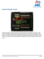
3.3V is the jumper has been set) in the DIO connector bank, the 5V pins in the Analog bank, the 3.3V
pins in the SPI and I2C bank and the 5V and 3.3V pins in the MXP bank.
The controller will remain in this state until the voltage rises above 6.3V (return to Stage 2) or
drops below the trigger for the next stage of the brownout
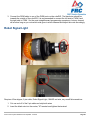
Stage 3 - Device Blackout
Voltage Trigger - 4.5V
Below 4.5V the device may blackout. The exact voltage may be lower than this and depends on the
load on the device.
The controller will remain in this state until the voltage rises above 4.65V when the device will
begin the normal boot sequence.
2015 Control System Hardware Last Updated: 1/1/2015
Page 107