1
2015 Control System Hardware
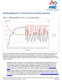
cause an issue. This gives us some bounds on setting our sustained current draw. For the
purposes of this exercise, we'll set our limit at 180A.
2. List out the different functions of your robot such as drivetrain, manipulator, main game
mechanism, etc.
3. Start assigning your available current to these functions. You will likely find that you run out
pretty quickly. Many teams gear their drivetrain to have enough torque to slip their wheels at
40-50A of current draw per motor. If we have 4 motors on the drivetrain, that eats up most, or
even exceeds, our power budget! This means that we may need to put together a few scenarios
and understand what functions can (and need to be) be used at the same time. In many cases,
this will mean that you really need to limit the current draw of the other functions if/while your
robot is maxing out the drivetrain (such as trying to push something). Benchmarking the "driving"
current requirements of a drivetrain for some of these alternative scenarios is a little more
complex, as it depends on many factors such as number of motors, robot weight, gearing, and
efficiency. Current numbers for other functions can be done by calculating the power required to
complete the function and estimating efficiency (if the mechanism has not been designed) or by
determining the torque load on the motor and using the torque-current curve to determine the
current draw of the motos.
4. If you have determined mutually exclusive functions in your analysis, consider enforcing the
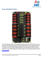
exclusion in software. You may also use the current monitoring of the PDP (covered in more
detail below) in your robot program to provide output limits or exclusions dynamically (such as
don't run a mechanism motor when the drivetrain current is over X or only let the motor run up to
half output when the drivetrain current is over Y).
Measuring Current Draw using the PDP
The FRC Driver Station works in conjunction with the roboRIO and PDP to extract logged data from the
PDP and log it on your DS PC. A viewer for this data is still under development.
In the meantime, teams can use their robot code and manual logging, a LabVIEW front panel or the
SmartDashboard to visualize current draw on their robot as mechanisms are developed. In LabVIEW,
you can read the current on a PDP channel using the PDP Channel Current VI found on the Power
pallete. For C++ and Java teams, use the PowerDistributionPanel class as described in the Power
Distribution Panel article. Plotting this information over time (easiest with a LV Front Panel or with the
SmartDashboard by using a Graph indicator can provide information to compare against and update
your power budget or can locate mechanisms which do not seem to be performing as expected (due to
incorrect load calculation, incorrect efficiency assumptions, or mechanism issues such as binding).
2015 Control System Hardware Last Updated: 1/1/2015
Page 109