1
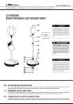
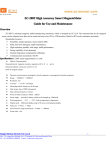
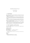
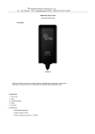
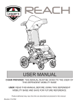
US
RACER ERGOMETER 700M
USER MANUAL
US330400000017
Dear customer!
The manufacturer is constantly improving all types and models. Please understand
that changes to the delivered product in terms of form, features and technology are
thus possible at any time. Therefore no claims may be derived from the information,
illustrations and descriptions in this manual.
Reprint, duplication or translation, also of excerpts, is not permitted without the
written permission of the manufacturer.
All rights according to the law or to copyright law are expressly reserved by the
manufacturer.
Subject to alterations
www.ultega.net
US
INDEX
SAFETY INSTRUCTION
1
BEFORE YOU BEGIN
2
COMPONENTS - PARTS
3
COMPONENTS - FIXINGS
4
ASSEMBLY STEP
5
COMPUTER FUNCTION
10
TENSION ADJUSTMENT
11
CARE AND MAINTAINANCE
12
TROUBLE SHOOTING
12
DISPLAY OF APPLIANCE
12
TRAINING ORGANISATION
13
CONDITIONING GUIDELINES
14
WARM-UP AND COOL-DOWN
15
PARTS LIST
17
EXPLODED
18
US
www.ultega.net
SAFETY INSTRUCTION
WARNING :
Safety Instruction before using the ULTEGA Racer 700M.
To reduce the risk of serious injury, read the following.
1. Use the ULTEGA Racer 700M only on a level surface.
2. Keep children and pets away from this equipment at all times.
3. The ULTEGA Racer 700M should not be used by persons weighing more than 120kgs.
4. The ULTEGA Racer 700M should be used by only one person at a time.
5. Be careful to maintain your balance while using, mounting, dismounting, folding, unfolding or
assembling the ULTEGA Racer 700M, loss of balance may result in a fall and serious bodily injury.
6. Use the ULTEGA Racer 700M only as described in the manual.
7. Before using this equipment to exercise, always do stretching exercises to properly warm up.
8. Always make sure all bolts and nuts are tightened prior to each use.
WARNING
Before starting any exercise or conditioning program you should consult your personal physician to see
if you require a complete physical exam. This is especially important if you are over the age of 35, have
never exercised before, are pregnant, or sufer from any illness.
1
US
www.ultega.net
BEFORE YOU BEGIN
Thank you for choosing the ULTEGA Racer 700M. We take great pride in producing this quality product
and hope it will provide many hours of quality exercise to make you feel better, look better and enjoy life
to its fullest.
Yes, it’s a proven fact that a regular exercise program can improve your physical and mental health. Too
often, our busy lifestyles limit our time and opportunity to exercise.
The ULTEGA Racer 700M provides a convenient and simple method to get your body in shape and to
achieve a healthier lifestyle.
Please review the drawing below and familiarize yourself with the parts that are labeled.
Computer
Handlebar
Tension Knob
Upright Post
Seat
Chain Cover
Front Stabilizer
Pedal (Right)
Rear Stabilizer
2
www.ultega.net
US
COMPONENTS - PARTS
No.1 Main Frame x 1pc
No.3 Seat Post x 1
No.7 Handlebar x 1
No.8 Computer x 1
No.9 Front Cover x 1
No.2 Front Post x 1
No.72 Bottle x 1
No.10 Left Pedal x 1
No.12 Seat x 1
No.6 Rear Stabilizer x 1
No.71 Bottle Holder x 1
No.4 Right Pedal x 1
No.5 Front Stabilizer x 1
3
www.ultega.net
US
COMPONENTS - FIXINGS
No.26 (ø8.5 x ø16 x 1.5T) Flat washer x 1pc
No.15 (ø8.3 x ø20 x 1.5T) Curved Washer x 4pcs
No.11 Spacer x 1pc
No.16 (M8) Domed Nut x 4pcs
No.13 T Type Knob x 1pc
No.21 (M8x70L) Carriage Bolt x 4pcs
No.14 Clamp Cover x 1pc
FIXING TOOLS
Universal Wrench x 2
Allen Wrench x 1
NOTE :
The described parts are all you need to assemble this machine.
Before starting assembly, please check the hardware packing to make sure they are included.
4
www.ultega.net
US
ASSEMBLY STEP
Step 1
• Attach Front Stabilizer (5) to Main Frame (1)
using 2pcs x Allen Bolt (21), Curved Washer (15)
21
5
and Domed Nut (16).
• Attach Front Stabilizer (6) to Main Frame (1)
using 2pcs x Allen Bolt (21), Curved Washer (15)
and Domed Nut (16).
15
16
16
15
1
16
15
6
21
Step 2
• Attach the right and left pedal straps to the
Right And Left Pedals (4/10). Note: The end with
four adjustable holes must be set outwards.
10
• Attach the Left And Right Pedals (10/4) to the
Left And Right Crank Arms (25). Note: The pedals
and crank arms are marked with R & L. The right
pedal (R) should be threaded in clockwise and
25R
the left pedal (L) should be threaded counter-
4
1
clockwise.
5
www.ultega.net
US
ASSEMBLY STEP
Step 3
• Pull out the Quick Release Knob (17) from Main Frame (1). Insert Seat Post (3) to Main Frame (1).
Attach Seat (12) to Seat Post (3) and fasten the screw.
• Line up the holes and secure seat in position with the Quick Release Knob (17).
12
3
17
1
6
www.ultega.net
US
ASSEMBLY STEP
Step 4
• Insert the Front Post (2) through the Front Cover (9) and connect the Upper Computer Wire (24) from
the Front Post (2) to the Lower Computer Wire (22).
• Connect the Wire Of Tension Control Knob (37) with Extension Control Wire (19).
• Insert Front Post (2) into Main Frame (1). Secure using 4sets x Spring Washer (74), Curved Washer (15)
and Allen Screw (20).
37
24
22
2
19
22
74
15
15
20
74
20
37
19
24
22
1
CAUTION:
• Assemble product carefully.
• Do not pinch or damage the wires.
• Avoid damaging wires with bolts.
7
www.ultega.net
US
ASSEMBLY STEP
Step 5
• Attach Handlebar (7) to Front Post (2).
• Pull the Pulse Wire (23) through the hole at the top of the Front Post (2). Then secure using Clamp
Cover (14), one Spacer (11) and Flat Washer (26) and T Type Knob (13).
• Connect Middle Computer Wire (24) to Computer (8) and connect the Hand Pulse Wire (23) to the
Computer (8).
• Attach the Computer (8) onto the bracket of the Front Post (2). Secure by using 4pcs x Screw (18)
8
7
24
23
18
14
26
11
13
2
8
www.ultega.net
US
ASSEMBLY STEP
Step 6
• Attach the Bottle Holder (71) to the Front Post (2), secure by using 2pcs x Screw (70).
72
70
71
2
Recheck
all bolts, nuts and pedals are
tightened securely
before use the machine
9
US
www.ultega.net
COMPUTER FUNCTION
KEY FUNCTION:
There are 3 button keys and the function
description as follows:
1. Up key: During the STOP mode, press the key
to increase the value of Time, Distance and
Calories.
2. MODE key:
a. Press the key can accept these setting values
of TIME, DISTANCE and CALORIE.
b. During the STOP mode, by holding this key
for over two seconds then the computer will
re-power-on.
c. During the exercise mode, press the key can
check the function from SCAN - TIME - SPEED
-ODO - DISTANCE - CALORIE - RPM - PULSE for
a circle.
3. DOWN key: During the setting mode, press
the key to decrease the value of Time, Distance
and Calories .
FUNCTIONS AND FEATURES:
1. SCAN: At the exercise mode, press the MODE
key until appears the SCAN on the LCD.
Monitor will display the following function and
each function will keep 6 seconds on the main
screen. TIME-SPEED/Count-ODO/Total COUNT
-DISTANCE-CALORIE-RPM -PULSE
2. TIME: Shows your elapsed workout time in
minutes and seconds. Your computer will
automatically count up from 0:00 to 99:59 in
one second intervals. You many also program
your computer to count down from a set
value by using the UP and DOWN keys. If you
continue exercising once the time has reached
0:00, the computer will begin beeping, and
reset itself to the original time set, letting you
know your workout is done.
3. SPEED: Displays your workout speed value in
KM/MILE per hour from 0.0 to 999.9.
4. DISTANCE: Displays the accumulative distance
traveled during each workout up to a
maximum of 99.99KM/MILE.
5. CALORIES: Your computer will estimate the
cumulative calories burned at any given time
during your workout.
6. PULSE: Your computer displays your pulse rate
in beats per minute during your workout. If
no pulse signal input then the computer will
display “P” on the window.
7. RPM: Your pedal cadence.
SLEEP MODE:
The monitor will entry SLEEP mode (LCD of ) when
there is no signal input and no key be pressed after
4 minutes. Press any key or speed in,can wake up
system from sleep mode.
ERROR MESSAGE:
E: The speed over than9 99.9 MPH/KPH then the
computer will display “E”.
Warning:
Please make sure to put or replace two new
batteries at the same time.
10
US
www.ultega.net
TENSION ADJUSTMENT
For minute tension adjustment, simply use the
tension adjustment knob (37) found beneath the
console. To increase tension, turn clockwise (+), to
decrease tension, turn anti-clockwise (-).
Fat burning
The body starts to burn fat at approx. 60% of the
maximum pulse rate.
To reach an optimum burning rate. it is advisable
to keep the pulse rate between 60% - 70% of
the maximum pulse rate. The optimum training
amount consists of three workouts per week 30
minutes each. For example:
Training Tips
To achieve a considerable improvement of your
physical resistance and your health, some aspects
of how to ind the most eicient amount of
training should be followed: if you have not been
physically active for a long period of time, please
consult your general physician before starting an
exercise regimen.
You are 52years of age and would like to start
exercising.
Maximum pulse rate = 220 – 52(age) = 168 pulse/
min
Minimum pulse rate = 168 x 0.6 = 101 pulse/min
Highest pulse rate = 168 x 0.7 = 117 pulse/min
Intensity
To achieve maximum results the right intensity has
to be chosen, The heart rate is used as guideline.
As a rule of thumb the following formula is
commonly used: Maximum pulse rate = 220 – Age
While exercising the pulse rate should always be
between 60% - 85% of the maximum pulse rate.
For your personal training rates please see the
pulse rate chart.
During the irst weeks it is advisable to start
with a pulse rate of 101, afterwards increase it to
117. With increasing improvement of itness the
training intensity should be increased to 70% 85% of your maximum pulse rate. This can be done
by increasing the resistance, a higher frequency or
longer training
When starting to exercise you should keep your
rate at 60% of your maximum pulse rate in the irst
couple of weeks.
With increasing improvement of itness the pulse
rate should be slowly increased to 85% of your
maximum pulse rate.
11
US
www.ultega.net
CARE AND MAINTAINANCE
Attention: Always remove plug from socket before
cleaning or maintenance!
Sweat, dust and dirt particles can change and damage the
surface of your Ergometer after just a few weeks. This is
why it’s important to clean the Ergometer regularly. Use
only mild, standard detergents for cleaning. Do not clean
the Ergometer with water but only with a moist cloth.
Attention: Never use aggressive detergents or
solvents. These will damage the plastic parts.
In order to maintain the high safety level, regularly check the
Ergometer and the network adapter for damage and wear.
These checks should be carried out at least once a month.
Defective parts must be replaced immediately. The
Ergometer must not be accessible to users while it is under
repair! Parts such as the grips and the pedals are particularly
subject to wear. Always ensure that securing bolts and nuts
have not become loose.
No display or no function.
TROUBLE SHOOTING
The pulse display does not function or is faulty.
Check that the jack of the network adapter is properly
inserted. Check that the power socket is working by plugging
in another appliance. Check the jack connections within the
Ergometer (see “Assembly” chapter).
The pedal resistance cannot be adjusted.
The program may have been interrupted. Start it again with
the START/STOP key.
During the exercise session the computer no longer
counts units.
Place both hands simultaneously on the pulse sensors.
Computer displays malfunction.
Press the START/STOP key and select a program. If necessary
adjust the pedal resistance with the UP/DOWN keys.
Remove the power plug from the socket. Wait a few seconds
and then re-insert it in the socket.
DISPLAY OF APPLIANCE
Old appliances may not be disposed of as
domestic waste!!
Should it no longer be possible to use the appliance or
the network adapter, then the consumer is legally obliged
to separate old appliances from domestic waste and to
return them to a collection point of his municipality or
urban district.
This ensures that the old appliances can be processed
appropriately and negative environmental efects are
avoided.
This is why electrical appliances are marked with the symbol
illustrated here.
12
US
www.ultega.net
TRAINING ORGANISATION
Warm-up :
Training session :
Before every training session you should warm-up for 5-10 minutes. Here you can do
some stretching and training with low resistance.
During the actual training a rate of 70% - 85% of the maximum pulse rate should be
chosen.
The time-length of your training session can be calculated with the following rule of thumb:
Daily training session : approx. 10 min. per unit
2-3 x per week :
approx. 30 min. per unit
1-2 x per week :
approx. 60 min. per unit
Cool down :
To introduce an efective cool-down of the muscles and the metabolism the intensity
should be drastically decreased during the last 5-10 minutes, Stretching is also
helpful for the prevention of muscle aches.
Success
Even after a short period of regular exercises you will notice that you constantly have to increase the
resistance to reach your optimum pulse rate. The units will be continuously easier and you will feel a lot
itter during your normal day.
For this achievement you should motivate yourself to exercise regularly. Choose ixed hours for your
training session and do not start training too aggressively.
An old quote amongst sportsmen says:“The most diicult thing about training is to start it.”
We wish you lots of fun and success with your ULTEGA RACER 600.
Training Pulse Rate Reference Chart
13
www.ultega.net
US
CONDITIONING GUIDELINES
How you begin your exercise program depends on your physical condition. If you have been inactive for
several years, or are severely overweight, you must start slowly and increase your time on the equipment;
a few minutes per workout.
Initially, you may be able to exercise only for a few minutes in your target zone, however, your aerobic
itness will improve over the next six to eight weeks. Don’t be discouraged if it takes longer. It’s important
to work at your own pace. Ultimately, you’ll be able to exercise continuously for 30 minutes. The better
your aerobic itness, the harder you will have to work to stay in your target zone. Please remember these
essentials :
• Have your doctor review your training and diet programs to advise you of a workout routine you should
adopt.
• Begin your training program slowly with realistic goals that have been set by you and your doctor.
• Monitor your pulse frequently. Establish your target heart rate based on your age and condition.
• Set up your equipment on a lat, even surface at least 3 feet from walls and furniture.
EXERCISE INTENSITY
To maximize the beneits of exercising, it is important to exercise with
the proper intensity. The proper intensity level can be found by using
your heart rate as a guide. For efective aerobic exercise, your heart
rate should be maintained at a level between 70% and 85% of your
maximum heart rate as you exercise. This is known as your target zone.
You can ind your target zone in the table below. Target zones are listed
for both unconditioned and conditioned persons according to age.
During the irst few months of your exercise program, keep your heart
rate near the low end of your target zone as you exercise. After a few
months, your heart rate can be increased gradually until it is near the
middle of your target zone as you exercise.
To measure your heart rate, stop exercising but continue moving your
legs or walking around and place two ingers on your wrist. Take a
six-second heartbeat count and multiply the results by 10 to ind your
heart rate. For example, if your six-second heartbeat count is 14, your
heart rate is 140 beats per minute. (A six-seconds count is used because
your heart rate will drop rapidly when you stop exercising.) Adjust the
intensity of your exercise until your heart rate is at the proper level.
14
AGE
UNCONDITIONED
TARGET ZONE
(BEATS/MINS)
CONDITIONED
TARGET ZONE
(BEATS/MINS)
20
138-167
133-162
25
136-166
132-132
30
135-164
130-158
35
134-162
129-156
40
132-161
127-155
45
131-159
125-153
50
129-156
124-150
55
127-155
122-149
60
126-153
121-147
65
125-151
119-145
70
123-150
118-144
75
122-147
117-142
80
120-146
115-140
85
118-144
114-139
US
www.ultega.net
WARM-UP AND COOL-DOWN
WORKOUT GUIDELINES
Each workout should include the following three parts:
A warm-up, consisting of 5 to 10 minutes of stretching and light exercise. A proper warm-up increases
your body temperature, heart rate, and circulation in preparation for exercise.
Training zone exercise, consisting of 20 to 30 minutes of exercising with your heart rate in your training
zone. (Note: During the irst few weeks of your exercise program, do not keep your heart rate in your
training zone for longer than 20 minutes.)
A cool-down, with 5 to 10 minutes of stretching. This will increase the lexibility of your muscles and will
help to prevent post-exercise problems.
Exercise Frequency
To maintain or improve your condition, plan three workouts each week, with at least one day of rest
between workouts. After a few months of regular exercise, you may complete up to ive workouts each
week, if desired. Remember, the key to success is when exercising becomes a regular and enjoyable part
of your life.
SUGGESTED STRETCHES
The correct form for several basic stretches is shown at the right. Move slowly as you stretch-never
bounce.
1. Toe Touch Stretch
Stand with your knees bent slightly and slowly bend forward from your
hips. Allow your back and shoulders to relax as you reach down toward
your toes as far as possible. Hold for 15 counts, then relax. Repeat 3 times.
Stretches: Hamstrings, back of knees and back.
2. Hamstring Stretch
Sit with one leg extended. Bring the sole of the opposite foot toward
you and rest it against the inner thigh of your extended leg. Reach
toward your toes as far as possible. Hold for 15 counts, then relax.
Repeat 3 times for each leg. Stretches: Hamstrings, lower back and
groin.
15
US
WARM-UP AND COOL-DOWN
3. Calf/Achilles Stretch
With one leg in front of the other, reach forward and place your
hands against a wall. Keep your back leg straight and your back
foot lat on the loor. Bend your front leg, lean forward and move
your hips toward the wall. Hold for 15 counts, then relax. Repeat
3 times for each leg. To cause further stretching of the achilles
tendons, bend your back leg as well. Stretches: Calves, achilles
tendons and ankles.
4. Quadriceps Stretch
With one hand against a wall for balance, reach back and grasp
one foot with your other hand. Bring your heel as close to your
buttocks as possible. Hold for 15 counts, then relax. Repeat 3 times
for each leg. Stretches: Quadriceps and hip muscles.
5. Inner Thigh Stretch
Sit with the soles of your feet together and your knees outward.
Pull your feet toward your groin area as far as possible. Hold for 15
counts, then relax. Repeat 3 times. Stretches: Quadriceps and hip
muscles.
16
www.ultega.net
www.ultega.net
US
PART LIST
No.
Description
Qt’y
No.
Description
Qt’y
1
Main Frame
1
39
Square End Cap
1
2
Front Post
1
40
Seat Bushing
1
3
Seat Post
1
41
Sliding Tube
1
4
Right Pedal
1
42
Spacer (ø10.2 x ø15.9 x 4.3L)
1
5
Front Stabilizer
1
43
Flywheel (5kg)
1
6
Rear Stabilizer
1
44
BB Part
1
7
Handlebar
1
45
Club Knob (ø60 x 30L)
1
8
Computer
1
46
Transportation Wheel (ø60 x 1.2T)
2
9
Front Cover
1
47
Leveling End Cap (ø60 x 1.2T)
2
10
Left Pedal
1
48
Screw (M5 x 55L)
1
11
Spacer
1
49
Magnet Assembly
1
12
Seat
1
50
Right Chain Cover
1
13
T Type Knob
1
51
Left Chain Cover
1
14
Clamp Cover
1
52
Crank Cover
2
15
Curved Washer (ø8.3 x ø20 x 1.5T)
8
53
Grommet (ø14.5 x 1H)
1
16
Domed Nut (M8 x 16H)
4
54
Phillips Screw (M4 x 20L)
4
17
Quick Release Knob (ø56 x 80L)
1
55
Curved Washer (ø5.5 x ø20 x 1.5T)
1
18
Screw (M5 x 10L)
4
56
Idle Wheel
1
19
Adaptor
1
57
Belt
1
20
Allen Screw (M8 x 20L)
4
58
Foam Grip (ø23 x ø33 x 590L)
2
21
Carriage Bolt (M8 x 70L)
4
59
Sliding Block
1
22
Lower Computer Wire
1
60
Crossing Wrench (130L x 29W x 4.0T)
2
23
Pulse Wire
2
61
Allen Wrench (90L x 35W)
1
24
Upper Computer Wire
1
62
Hand Pulse Sensor
2
25
Crank with Pulley
1
63
Spring For Magnet Assembly (ø14 x 66L)
1
26
Flat Washer (ø8.5 x ø16 x 1.5T)
1
64
Spring For Idle Wheel (ø16 x 75L)
1
27
Self-Tapping Screw (M4 x 20L)
12
65
Bearing
2
28
Flat Washer (ø4.3 x ø12 x 1.0T)
2
66
C-Clip
2
29
Flat Washer (ø10.5 x ø20 x 1.8T)
3
67
France Nut (M10 x 1.25P)
2
30
Hex Head Screw (M10 x 20L)
1
68
Hex Head Screw (M10 x 105L)
1
31
Washer (ø8.5 x ø28 x 1.5T)
1
69
Crank Cover
2
32
Hex Head Bolt (M5 x 30L)
1
70
Screw (M5 x 15L)
2
33
Hex Head Nut (M5 x 5.0T)
2
71
Bottle Holder
1
34
Cover for Sliding Seat
1
72
Bottle
1
35
Nylon Locknut (M10 x 10T)
2
73
Self-Tapping Screw (M3 x 12L)
1
36
Sensor Bracket
1
74
Spring Washer (M8)
4
37
Power Wire
1
75
Screw (M5 x 20L)
1
38
End Cap for Handlebar
2
17
18
10
69
25L
67
66 65
44
52
4
54
25R
69
67
66
65
57
46
54
29
35
21
27
37
48
55
18
50
63
5
49
33
68
8
32
15
16
43
19
71
2
24
74
15
27
28
38
40
17
7
11
34
26
16
15
36 73
22
9
20
70
72
14
62
27
13
23
3
53
1
62
75
6
39
47
30
31
56
21
42
29
35
51
29
45
59
41
12
58
64
27
54
27
27
52
27
61
60
27
27
27
54
60
US
www.ultega.net
EXPLODED
US
WARRANTY
In the event of a warranty claim, please irst contact our service hotline or send us an e-mail.
Manufacturer & Service
Summary USA Inc.
1 Riverside Road, Suite 204 Riverside, IL 60546
Service hotline: 888-278-6970
E-mail : [email protected]
Internet : www.ultega.net