1
EECS 461 Winter 2009
Lab 7: Controller Area Network
1
Overview
The design of a complex control system often requires coordinated activity of many sensors, actuators and
other devices that are separated by some significant distance. As a result, the design must provide some
means of communication. One solution is to dedicate a physical connection between every pair of components of the system. This solution is relatively reliable because a break in one connection only affects
the components on either end of the broken connection. Unfortunately, this type of communication does
not scale well because adding just one component requires additional wires to every part of the original
system. A network solution to the communication problem connects all parts of the control system to one
communication channel and all the necessary communication is achieved by sharing the channel. Compared
with dedicated connections, a network is more scalable, less expensive, and less complicated to build and
maintain. These advantages of a network must be weighed against possible disadvantages, including the
fact that communications in a control system are often time critical, and it is thus necessary to guarantee a
worst-case response time even though many devices must share the same network.
In addition to the physical media of the network, a network protocol is necessary to define standards for
communicating on the network. The network protocol describes, among many things, how to manage shared
access to the network, how to route information, and how to handle errors. In this lab, we will use the
CAN (controller area network) protocol to write network applications because the MPC5553 provides two
CAN modules that implement the CAN protocol. We will investigate the issues involved in using a CAN
network, such as network delay and message prioritization, by writing two networked programs. For the first
program, you will distribute your virtual wall across two 5553 microcontrollers. The second program will
form a virtual chain by virtually connecting each wheel to the next over the network.
2
2.1
Design Specifications
Controller Area Network
CAN was developed in the 1980s in Germany to serve as a serial communications bus for automotive electronics. It allowed automotive companies to reduce the number of sensors and wiring looms required for the
electronic systems, thereby significantly reducing the cost and weight of those systems. Information about
the CAN specification is available online at http://www.can.bosch.com.
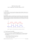
CAN networks are designed to send short, prioritized messages. Every CAN message has an identifier,
which is commonly used to indicate the contents of the message. The identifier also serves as the message
priority, such that numerically lower identifiers have higher priority. When a message is sent, neither its
source nor its destination is specified; all nodes in the network receive the message and then perform a test
to determine whether or not the message is relevant to them. Once the first bit of a message is on the
network, no other messages can begin transmission. If two nodes happen to begin communication at exactly
the same time, the message with the higher priority is transmitted and the other message is stopped and
restarted after the network becomes available again. The arbitration technique that permits messages of
higher priority to be transmitted first depends on the electrical properties of the network, and as such, does
not delay the transmission of the higher priority message. This guarantees that the CAN bus is used with
EECS 461: Embedded Control Systems
1
Winter 2009
Lab 7
Controller Area Network
the highest possible efficiency.
The original CAN standard (CAN 2.0A) provided for 11-bit message identifiers. The CAN 2.0B specification supports both the original 11-bit identifier (standard) and 29-bit identifiers (extended).
2.2
Hardware
The MPC5553 has two FlexCAN modules that implement the CAN protocol. Each FlexCAN module contains 64 message buffers that can be used for sending and receiving messages. Using multiple buffers allows
several buffers to contain messages waiting to be transmitted, have several buffers waiting to receive messages
off the CAN bus and have several buffers holding messages received but not yet read by software. Any of the
64 buffers can be used for receiving or transmitting. The only distinction among the buffers is that buffers
0 through 13 share one acceptance mask, as do 16 through 63, but buffers 14 and 15 each have their own
acceptance mask. For more information about the use of acceptance masks in receiving messages, consult
section 22.3.3 of the MPC5553 User’s Manual.
The FlexCAN modules operate using the CAN 2.0B controller protocol, which means that message IDs
can be in either standard or extended structure. The processor determines the length of the ID by looking
at the extended ID (IDE) bit for each message buffer. (See 22.3.2 the User’s Manual) Because we will be
using only a small number of different message IDs, the standard ID structure is sufficient for this lab. Be
careful to use only 11-bit message IDs. Note that an 11-bit ID is distinct from a 29-bit ID even if they
are the same numeric value. See Chapter 22, “FlexCAN2 Controller Area Network” of the MPC5553 User’s
Manual for more information about the FlexCAN modules.
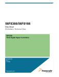
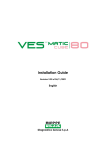
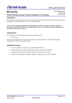
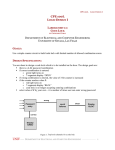
The ID of a CAN message identifies the contents of a message and determines the message’s priority. Each
lab station is assigned a unique range of IDs so that receivers can determine the source of each message. The
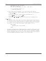
base ID for each lab station is given by Figure 1. In addition, for each type of CAN transmission required,
there is a particular offset that is added to your lab stations base ID to determine that CAN message’s ID.
Be sure to follow these specifications.
10
4
Printer
r
20
30
3
60
50
40
Soln Code:
100
Figure 1: This map of the lab indicates the base ID for messages from each lab station. For instance, the
first lab station can use IDs 10 through 19.
We will also use the haptic wheel and the features of the MPC5553 required to control it.
2.3
Software
flexcan.h and flexcan.c
EECS 461: Embedded Control Systems
2
Winter 2009
Lab 7
Controller Area Network
The files flexcan.c and flexcan.h are driver files that contain functions for initializing the FlexCAN
module and for sending and receiving CAN messages. The following is a short reference to the
driver functions you will use.
• int can init(struct FLEXCAN2 tag *can)
This driver function accepts a pointer to the base address of the CAN module to configure
(for this lab, &CAN A ). Within can init(), the register of interest that we will configure is the
CAN A.CR control register. See the 5553 user manual section 22.3.3.2 for description of the
bit fields of this register. For this lab, we will use a CAN network bit-rate of 500kBits/sec,
which is the fundamental rate of the serial oscillator on our development boards, separate
from the system clock. Configuration of the CAN A.CR fields is completed already in
flexcan.c.
• int can set rxisr(void (*fctn ptr)())
This driver function sets fctn ptr as the ISR to call in response to a message-received IRQ.
After calling this function to specify your ISR, call can rxbuff init() with doIRQ set to 1.
can rxbuff init() will initialize a buffer to receive a message and generate an IRQ when a
message is received. Using an ISR is more efficient than polling a buffer to check for received
message.
The following sample code shows how a function can be specified as an ISR that is called
when a CAN message is received and generates an IRQ.
void my_CAN_rxISR();
int main() {
...
can_set_rxisr(my_CAN_rxISR);
...
• int can rxbuff init(struct FLEXCAN2 tag can, int buff num, int id, int doIRQ)
This driver function initializes one of the message buffers as an active receive buffer on the
CAN module specified. The number of the buffer to initialize is set by buff num and the
ID that the buffer should receive is determined by id. If you want an IRQ to be generated
when a message is received (which you do for this lab), then set doIRQ equal to 1. Before
calling this function with doIRQ set to 1, you must have specified an ISR function by calling can set rxisr() with your ISR as the function argument. The implementation of this
function first sets the CODE of the buffer to inactive. Then the ID LOW and ID HIGH
registers are set with the message ID that the buffer should receive. The CODE is then set
to “receive active”. This process can be briefly summarized:
Driver Procedure:
1. The buffer’s CODE is set to receive disabled (0x0).
2. The message ID of the buffer is set.
3. The buffer’s IMASK bit is set if an IRQ should be generated.
4. The buffer’s CODE is set to receive active (0x4).
After the buffer is configured as an active receive buffer, it may receive a CAN message with
a matching ID at any time. Upon receiving a message, an IRQ will be generated and your
ISR function will be called to receive the message.
The following sample code configures buffer 5 of the CAN A module to receive a message with a standard ID of 2 (acceptance of the IDs is based on the global acceptance mask)
and generate an IRQ when a message is received.
if( can_rxbuff_init( &CAN_A, 5, can_build_std_ID( 2, 0 ), 1 ) != 0 )
exit(-2); /* failed to initialize buffer */
EECS 461: Embedded Control Systems
3
Winter 2009
Lab 7
Controller Area Network
• int can rxmsg(struct FLEXCAN2 tag *can, CAN RXBUFF *buff, uint8 t renew)
This function receives a CAN message from the specified CAN module and buffer if there is
a new message to receive. This function does not block, rather it checks for a message and
either reads the message in the buffer, if it exists, or it exits immediately. If a message is
received, the renew parameter specifies whether or not the buffer should be reactivated.
Driver Procedure:
1. The buffer status flag is checked and function exits if flag is not raised.
2. Reading the control-status register fields lock the buffer.
3. Copy the message ID, message data, and message length to buff.
4. If renew equals zero, the buffer is deactivated and the buffer’s IMASK bit is
cleared.
5. The free running timer is read to unlock the buffer.
The following sample code checks buffer 2 of the CAN A module for a message. Buffer
2 would have already been initialized as an active receive buffer. This code would be
appropriate within an ISR that is called whenever a CAN message is received.
CAN_RXBUFF buff;
int r;
double data;
buff.buff_num = 2;
r = can_rxmsg( &CAN_A, &buff, 1 /*renew*/);
if(r != 0)
exit (-2); /* error */
if(r == 0 && buff.length == 8)
/* receive the message */
memcpy( &data, buff.data, sizeof(data) );
• int can txmsg(struct FLEXCAN2 tag *can, struct txbuff *buff)
This function transmits a CAN message on the specified CAN module and buffer. Up to 8
bytes of data can be copied into the data member variable of buff and the length member
variable should be set to the number of bytes of data to transmit. This is not a blocking
function so the function returns without verifying that the message has been sent. The
buffer becomes inactive upon completing the transmission of a message, and the buffer’s
IFLAG bit is set to indicate that the transmission is complete. Note that the RTR bit for
the buffer is set to 0. The RTR bit must be dominant (0) in data frames and recessive (1)
in remote frames.
Driver Procedure:
1. The buffer’s CODE is set to transmit disabled (0x8).
2. The message ID, message data, and message length of the buffer are set.
3. The buffer’s IFLAG bit is cleared.
4. The buffer’s CODE is set to unconditional transmission (0xC).
5. The driver function exits.
6. When the CAN bus becomes available, the CAN message is sent.
The following sample code sends a message with a 4-byte payload from buffer 0 on CAN
module A with a standard ID of 200.
CAN_TXBUFF buff;
float pi = 3.141593;
buff.buff_num = 0;
EECS 461: Embedded Control Systems
4
Winter 2009
Lab 7
Controller Area Network
memcpy(buff.data, &pi, sizeof(pi));
buff.length = sizeof(pi);
buff.id = can_build_std_ID( 200 /*id*/, 0 /*not rtr*/);
if( can_txmsg(&CAN_A, &buff) != 0)
exit(-3); /* error */
A certain ordering of function calls must be observed when using the driver functions:
• Always call can init() to initialize a CAN module before calling any other driver functions
on that CAN module.
• Call can set rxisr() before calling can rxinit() with doISR equal to 1.
• Call can rxinit() before calling can rxmsg().
• Always use can build std ID(id) to convert lab stations id’s to meaningful can id’s.
lab7 template.c
For simplicity, we will be using a single .c file for this lab. Different functions in the file will be
automatically selected and compiled when using the lab 7 makefile. This is accomplished through
use of compiler directives, which in this case are #ifdef statements within lab7.c. For instance,
the following code is only compiled when using the compile command for User A:
#ifdef VWALLA
rxbuff.buff_num = vwA_rx_buffnum;
...
#endif
The makefile defines the symbol VWALLA only when it is run with command gmake vwalla,
and therefore the makefile is used to select which parts of the single .c file to compile or ignore.
This also means that it is not necessary to have complete code for the VWALLB (or VCHAIN )
sections to sucessfully compile your code for User A. You will notice these #ifdef and #endif
directives in multiple places within the template code. Do not delete them!
EECS 461: Embedded Control Systems
5
Winter 2009
Lab 7
3
Controller Area Network
Pre-Lab Assignment
Pre-lab questions must be done individually and handed in at the start of your lab section. You must also,
with your partner, design an initial version of your software before you come to your lab section. Your
software does not need to be completely debugged, but obviously more debugging before coming to lab means
less time you will spend in the lab.
In the first part of this lab, you will write a program that communicates with a neighboring lab station. We
will refer to the lab stations on either side as User A and User B. You need to write code for both User A
and User B.
1. Starting from the template lab7 template.c, write code for User A and B such that User B
implements a virtual spring-wall on User A’s wheel. The programs should interact as follows:
(a) The DEC ISR of User A reads its wheel angle in degrees as a 32-bit float. Use a 1kHz interrupt
frequency.
(b) The DEC ISR of User A transmits a 4-byte message with the wheel angle onto the CAN bus.
(c) User B’s CAN message-received ISR is called when User A’s message is received.
(d) User B’s CAN message-received ISR receives User A’s message and extracts the wheel angle.
(e) User B’s CAN message-received ISR calculates the virtual spring-wall torque in N-mm as a 32-bit
float.
(f) User B’s CAN message-received ISR transmits a 4-byte message with the torque value.
(g) User A’s CAN message-received ISR updates the motor torque with the value received from User
B.
There are two message types transmitted and they should adhere to the following specifications:
• User A Transmission: User A’s wheel angle in degrees as a 32-bit float
ID
= Base ID
Length = 4-bytes
Data[0] = Most significant byte of wheel angle
..
.
Data[3]
=
Least significant byte of wheel angle
• User B Transmission: Torque in N-mm as a 32-bit float
ID
= Base ID + 1
Length = 4-bytes
Data[0] = Most significant byte of wheel angle
..
.
Data[3]
=
Least significant byte of wheel angle
2. Continue to complete your lab7.c by implementing the “virtual chain” components. The
virtual chain connects your haptic wheel to your neighbors’ wheels with virtual springs and dampers.
When all groups are online, a chain of wheels will be formed, where each wheel is virtually connected to
the next with a spring and a damper. Use the spring and damping constants defined in lab7 template.c
in the virt chain() section. Moving your wheel will push and pull on the wheels of your immediate
neighbors, and if no one is holding the other wheels, all the wheels in the lab can be moved from just
one lab station.
We will denote the two neighbors of your lab station with indices i and j, such that θi and θj are
the angles of neighboring wheels and ωi and ωj are the velocities. Your wheel’s angle and velocity are
θ and ω, respectively. You can approximate your wheel’s velocity by ω = (θ(t) − θ(t − T )) /T , where
T denotes the period of the DEC (4 ms) and t is time.
EECS 461: Embedded Control Systems
6
Winter 2009
Lab 7
Controller Area Network
There are four torques acting on your wheel: two spring torques and two damping torques. The
spring torques are proportional to the relative displacement of your wheel to your neighbor’s wheel
and the damping torque is proportional to the relative velocity. Your program should apply a torque
to your wheel given by:
T = k(θi − θ) + k(θj − θ) + b(ωi − ω) + b(ωj − ω).
(1)
The torque should be re-calculated and applied to the wheel every 4 ms using a DEC ISR. Besides
maintaining the appropriate torque on your wheel, this ISR must broadcast your own wheel angle and
velocity. In summary, the ISR should perform the following steps:
(a) Read the wheel angle.
(b) Estimate the wheel velocity.
(c) Transmit an 8-byte message with the wheel angle and velocity, each as 32-bit float values.
(d) Compute the torque based on the most recent wheel angles and velocities from the two neighboring
lab stations.
(e) Update the motor torque.
There is one type of message transmitted by your ISR and it should strictly adhere to the following
specifications:
• Update of
ID
Length
Data[0]
wheel angle in degrees and velocity in deg/s
= Base ID+2
= 8-bytes
= Most significant byte of wheel angle (a 32-bit float)
..
.
Data[3]
Data[4]
=
=
..
.
Least signicant byte of wheel angle
Most significant byte of wheel velocity (a 32-bit float)
Data[7]
=
Least signicant byte of wheel angle
Two buffers need to be initialized to receive messages from your neighbors and the message-received
ISR will be called whenever a message is received from either neighbor. Rather than recalculating the
torque and updating the motor actuation whenever a message is received, use global variables (declared
as volatile) to store the most recently received values of θi , θj , ωi , and ωj . The DEC ISR can read
these global variables when it calculates the motor torque.
3. The time for one bit on the CAN bus, given the device drivers default settings, is 2 µs and a standardID CAN message containing 8 bytes of data requires 108 bits plus 3 interframe bits. Extra bits are
sometimes needed for “bit-stuffing,” but you may assume that no stuff-bits are inserted for this question.
What is the shortest sampling period for the virtual spring-wall that will result in less
than 25% bus utilization? Round up to the nearest millisecond and use this value for your program.
Remember that your group is sharing the CAN bus with 5 other lab stations (ignore the seventh station running solution code), and that User A and User B are transmitting messages with only 4-byte
payloads.
4. If the virtual spring-damper chain is run with a 4 ms loop time, what is the expected bus
utilization when all 6 lab stations are online?
EECS 461: Embedded Control Systems
7
Winter 2009
Lab 7
4
Controller Area Network
In-Lab Assignment
For your first networked application, your lab group will be working with the group at an adjacent computer.
Your target will communicate with your partner group’s target through the CAN bus. You should check
that there is a pair of wires connecting your MPC5553 board CAN interface to the CAN bus network. The
wires are connected with a DB9 connector, similar to the serial interface connection.
1. For the virtual spring-wall program, compare your setup of the CAN module with that of your partner
group’s computer. Each group should be using a base ID assigned according to their lab station as
shown in Figure 1. Make sure that you transmit messages with your own group’s ID and that you
listen for your partner group’s message ID, and be sure to use the standard 11-bit ID. Note that besides
identifying the lab station that sends the message, the ID also determines the priority of the message.
Assuming that 0 is the dominant bit-value on the network, messages with an ID of 1 will have the
highest priority.
2. Compile your virtual wall User A and User B programs using the commands “gmake vwalla” and
“gmake vwallb,” respectively. This will generate the lab7 vwalla.elf and lab7 vwallb.elf object files.
3. With the group at the adjacent computer, start up the debugger and run your code simultaneously.
Take turns as User A and User B.
Debugging:
• Use the CAN bus monitor program running on the seventh lab station to check that your group
is transmitting and examine the contents of your messages.
• Within the debugger, set a break-point on the CAN message-received ISR to determine if the
FlexCAN module is receiving the messages you expect. Failure to receive a message which is
visible on the CAN monitor means that the buffer you wish to receive the message is not correctly
configured. Some possibilities include: an incorrect ID, not requesting an IRQ for that buffer, or
over-writing the buffer’s initialization by transmitting a message in the buffer.
• If the adjacent group is not ready to test their code, you may test your code using the seventh lab
station running solution code. It automatically responds to every lab station’s User A message
using a base ID equal to your lab station’s base ID + 100. For example, a message ID of 20 would
receive a reply message with an ID of 121. The solution code also transmits User A messages for
every lab station following the same logic; User A message for the lab station with a base ID of
30 would have an ID of 130.
4. Using the code you developed in Lab 6, run the virtual wall locally using a spring constant of k =
1000 Nmm/degree (at the wheel) and without damping. Then using the same spring constant, run the
virtual wall over the CAN network. What differences do you notice?
5. Repeat step 4 for different values of k and see if the difference is still noticeable.
6. Implement your station in the virtual chain, and observe how it interacts with the other stations in
the chain. Compile using the command “gmake vchain”. The object file generated is lab7 vchain.elf.
EECS 461: Embedded Control Systems
8
Winter 2009
Lab 7
5
Controller Area Network
Post-Lab Assignment
1. Explain why a spring constant that did not produce chatter for the virtual wall system
you implemented in Lab 6 might produce chatter in the system you implemented in this
lab.
2. Explain what differences there would be in your program using the RTR requestor or
transmitter instead of the basic CAN transmitter and receiver.
3. Describe the possible problems due to communication drop-out and the dynamic addition
and removal of targets from the virtual chain. Consider large wheel displacements and
the free movement of the entire chain. How would you improve your code to handle these
issues?
4. You used global variables to pass data from the message-received ISR to the DEC ISR, which calculates the virtual chain torque.Is there any problem with updating the motor torque using the
global variables in the while-loop in the main() function? Is there any problem using the
global variables to calculate the virtual chain torque in the DEC ISR?
5. Include a well documented printout of your lab7.c file.
If you have comments that you feel would help improve the clarity or direction of this assignment, please
include them following your postlab solutions.
EECS 461: Embedded Control Systems
9
Winter 2009