1
GE Fanuc Automation
Programmable Control Products
TCP/IP Ethernet Communications
Station Manager Manual
GFK-1186G
May 2002
GFL-002
Warnings, Cautions, and Notes
as Used in this Publication
Warning
Warning notices are used in this publication to emphasize that hazardous voltages,
currents, temperatures, or other conditions that could cause personal injury exist in this
equipment or may be associated with its use.
In situations where inattention could cause either personal injury or damage to
equipment, a Warning notice is used.
Caution
Caution notices are used where equipment might be damaged if care is not taken.
Note
Notes merely call attention to information that is especially significant to understanding and
operating the equipment.
This document is based on information available at the time of its publication. While efforts
have been made to be accurate, the information contained herein does not purport to cover all
details or variations in hardware or software, nor to provide for every possible contingency in
connection with installation, operation, or maintenance. Features may be described herein
which are not present in all hardware and software systems. GE Fanuc Automation assumes no
obligation of notice to holders of this document with respect to changes subsequently made.
GE Fanuc Automation makes no representation or warranty, expressed, implied, or statutory
with respect to, and assumes no responsibility for the accuracy, completeness, sufficiency, or
usefulness of the information contained herein. No warranties of merchantability or fitness for
purpose shall apply.
The following are trademarks of GE Fanuc Automation North America, Inc.
Alarm Master
CIMPLICITY
CIMPLICITY 90–ADS
CIMSTAR
Field Control
FrameworX
GEnet
Genius
Helpmate
Logicmaster
Modelmaster
Motion Mate
ProLoop
PROMACRO
PowerMotion
PowerTRAC
Series 90
Series Five
Series One
Series Six
Series Three
VersaMax
VersaPoint
VersaPro
VuMaster
Workmaster
©Copyright 1989-2002 GE Fanuc Automation North America, Inc.
All Rights Reserved.
ii
Chapter 1
Introduction .........................................................................................................1-1
Station Manager Styles................................................................................................. 1-2
Station Manager Services ............................................................................................. 1-2
Quick Guide to the Manual .......................................................................................... 1-2
Chapter 2
Accessing the Station Manager ..........................................................................2-1
Connecting to the Station Manager................................................................................... 2-2
Local Operation of the Station Manager ...................................................................... 2-2
Terminal Emulators ...................................................................................................... 2-3
Remote Operation of the Station Manager ................................................................... 2-4
Chapter 3
Troubleshooting...................................................................................................3-1
Diagnostic Tools Available for Troubleshooting.............................................................. 3-2
States of the Ethernet Interface ......................................................................................... 3-3
Hardware Failure State ................................................................................................. 3-3
Software Load State...................................................................................................... 3-4
Waiting for IP Address State ........................................................................................ 3-4
The Maintenance State ................................................................................................. 3-5
The Operational State ................................................................................................... 3-5
Troubleshooting Using the LEDs ..................................................................................... 3-7
Powering–up the Ethernet Interface ............................................................................. 3-7
Problems During Power–up.......................................................................................... 3-7
States of the Series 90–30 Ethernet Interface (IC693CMM321) and the Type 2
Series 90-70 Ethernet Interface (IC697CMM742) ....................................................... 3-8
States of the Series 90–30 CPU364 Ethernet Interface .............................................. 3-10
States of the Series 90-30 CPU374 Ethernet Interface ............................................... 3-12
Troubleshooting Using the Station Manager .................................................................. 3-14
Tasks for Modules Using Style A Station Manager ................................................. 3-14
Tasks for Modules Using Style B Station Manager ................................................. 3-15
Exception Log .......................................................................................................... 3-16
When the STAT LED is OFF ..................................................................................... 3-17
When the STAT LED is ON....................................................................................... 3-18
Troubleshooting Using the PLC Fault Table .................................................................. 3-19
What to do if you Cannot Solve the Problem ................................................................. 3-22
Chapter 4
How to use the Station Manager ........................................................................4-1
Station Manager Security.................................................................................................. 4-1
Using the Monitor Commands.......................................................................................... 4-2
Useful Monitor Commands for Network Troubleshooting .......................................... 4-3
Using the Modify Commands....................................................................................... 4-4
Date and Time ............................................................................................................ 4-7
Station Manager Command Syntax .................................................................................. 4-8
Task Identification........................................................................................................ 4-8
Display Data Representation ........................................................................................ 4-9
Numeric Values .......................................................................................................... 4-9
Byte String Values...................................................................................................... 4-9
IP Addresses ............................................................................................................... 4-9
Station Manager Operation in Different Ethernet Interface States ................................. 4-10
Hardware Failure and Software Load States ............................................................ 4-10
Waiting for IP Address State.................................................................................... 4-10
Maintenance State .................................................................................................... 4-10
Operational State ...................................................................................................... 4-11
Differences in Station Manager Operation............................................................... 4-11
Chapter 5
Testing on the Network .......................................................................................5-1
Running a Network Test Using Style A Station Manager ................................................ 5-2
Performing a “Ping” Test.................................................................................................. 5-6
Pinging the Interface from a UNIX host or a PC Running TCP/IP Software............... 5-6
Pinging the Interface Using the Station Manager PING Command ............................. 5-6
Determining If an IP Address Has Already Been Used ............................................. 5-7
Network Test Data Sheet (for Style A Station Manager only)................................... 5-9
Chapter 6
Style A Station Manager Command Descriptions............................................6-1
Symbols Used in the Station Manager Commands........................................................... 6-1
Command Input Processing .............................................................................................. 6-2
BOOTP Command............................................................................................................ 6-3
BROWSEDDP Command ................................................................................................ 6-4
CHANNEL Command...................................................................................................... 6-5
CHDATE Command......................................................................................................... 6-6
CHLTIME Command ....................................................................................................... 6-6
CHMYNAME Command (Series 90–30 Ethernet Interface only) ................................... 6-7
CHNAMETBL Command (Series 90–30 Ethernet Interface only) .................................. 6-8
CHPARM Command ........................................................................................................ 6-9
What To Do If You Have Forgotten Your Password ................................................. 6-10
CHSNTP Command (Series 90–30 CPU364 and Series 90–70 Ethernet Interface (Type 2)
only) ................................................................................................................................ 6-11
CHSOSW Command ...................................................................................................... 6-12
CHTIME Command........................................................................................................ 6-13
CLEAR Command.......................................................................................................... 6-13
DATE Command ............................................................................................................ 6-14
EXS Command ............................................................................................................... 6-14
HELP Command ............................................................................................................. 6-15
KILLMS Command (Series 90–30 Ethernet Interface IC693CMM321-FH and later only)6-16
iv
KILLSS Command ......................................................................................................... 6-16
LOAD Command............................................................................................................ 6-17
LOG Command............................................................................................................... 6-18
LOGIN Command........................................................................................................... 6-19
LOGOUT Command....................................................................................................... 6-19
LTIME Command........................................................................................................... 6-20
MAINT Command.......................................................................................................... 6-20
MYNAME Command..................................................................................................... 6-20
NAMETBL Command.................................................................................................... 6-21
NET Command ............................................................................................................... 6-21
NODE Command............................................................................................................ 6-22
OK Command ................................................................................................................. 6-22
PARM Command............................................................................................................ 6-23
Style A Station Manager Advanced User Parameters ................................................ 6-24
PING Command.............................................................................................................. 6-28
PROG Command ............................................................................................................ 6-28
RDNIP Command (Series 90–70 Ethernet Interface (Type 2) only) .............................. 6-29
REM Command .............................................................................................................. 6-29
REPORT Command........................................................................................................ 6-30
REPP Command ............................................................................................................. 6-31
RESOLVE Command ..................................................................................................... 6-32
RESTART Command ..................................................................................................... 6-32
ROUTETBL Command (Series 90–30 CPU364 and Series 90–70 Ethernet Interface (Type
2) only)............................................................................................................................ 6-33
SNTP Command (Series 90–30 CPU364 and Series 90–70 Ethernet Interface (Type 2)
only) ................................................................................................................................ 6-34
SOSW Command............................................................................................................ 6-35
STAT Command............................................................................................................. 6-36
STOPP Command........................................................................................................... 6-36
STOPT Command........................................................................................................... 6-37
TALLY Command.......................................................................................................... 6-37
TEST Command ............................................................................................................. 6-38
TIME Command ............................................................................................................. 6-39
TRACE Command.......................................................................................................... 6-40
UDIS Command.............................................................................................................. 6-42
XCHANGE Command (Series 90–30 CPU364 and Series 90–70 Ethernet Interface (Type
2) only)............................................................................................................................ 6-42
v
Chapter 7
Style B Station Manager Command Descriptions............................................7-1
Symbols Used in the Station Manager Commands........................................................... 7-1
Command Input Processing .............................................................................................. 7-2
CHLTIME Command ....................................................................................................... 7-2
CHPARM Command ........................................................................................................ 7-3
What To Do If You Have Forgotten Your Password ................................................... 7-3
CHSOSW Command ........................................................................................................ 7-4
CHTIME Command.......................................................................................................... 7-5
CHTIME Command Format......................................................................................... 7-5
CLEAR Command............................................................................................................ 7-5
EGDREAD Command...................................................................................................... 7-6
EGDWRITE Command .................................................................................................... 7-6
HELP Command ............................................................................................................... 7-7
KILLSS Command ........................................................................................................... 7-8
LOG Command................................................................................................................. 7-9
LOGIN Command........................................................................................................... 7-11
LOGOUT Command....................................................................................................... 7-11
LTIME Command........................................................................................................... 7-12
NET Command ............................................................................................................... 7-12
NODE Command............................................................................................................ 7-13
OK Command ................................................................................................................. 7-13
PARM Command............................................................................................................ 7-14
Style B Station Manager Advanced User Parameters ................................................ 7-14
PING Command.............................................................................................................. 7-16
PLCREAD Command..................................................................................................... 7-17
PLCWRITE Command ................................................................................................... 7-17
PROG Command ............................................................................................................ 7-18
REM Command .............................................................................................................. 7-18
REPP Command ............................................................................................................. 7-19
Interpretation of Test Results ..................................................................................... 7-19
RESTART Command ..................................................................................................... 7-20
SNTP Command ............................................................................................................. 7-20
SOSW Command............................................................................................................ 7-21
STAT Command............................................................................................................. 7-22
STOPP Command........................................................................................................... 7-22
TALLY Command.......................................................................................................... 7-23
TRACE Command.......................................................................................................... 7-24
XCHANGE Command ................................................................................................... 7-26
vi
Appendix A
Glossary ............................................................................................................... A-1
Commonly Used Acronyms and Abbreviations .............................................................. A-2
Glossary of Terms............................................................................................................ A-3
Appendix B
Exception Log Event Descriptions .................................................................... B-1
Exception Log Events ...................................................................................................... B-2
1
Series 90-30 Ethernet Interface IC693CMM321-FG or later only.......................... B-2
Figure B-1. Visual Reference for Log Events within the Series 90 Ethernet Interface
Software for Style A Station Manager
B-3
Figure B-2. Visual Reference for Log Events within the Series 90 Ethernet Interface
Software for Style B Station Manager....................................................................... B-3
Exception Log Event Codes for Style A Station Manager .............................................. B-4
Exception Log Event Codes for Style B Station Manager............................................. B-48
Appendix C
Tally Descriptions............................................................................................... C-1
Tallies for Style A Station Manager ................................................................................ C-2
Tallies for Style B Station Manager............................................................................... C-12
Tally Counters ........................................................................................................... C-12
Appendix D
IP Address Assignment for Style B Station Manager ..................................... D-1
IP Address Assignment Using Telnet .............................................................................. D-1
The ‘setip’ Utility............................................................................................................. D-2
Appendix E
Status Codes in the Exception Log ................................................................... E-1
SCode Subsystem ID Definitions .....................................................................................E-2
SCode Error/Status Definitions for Subsystems ...............................................................E-3
Error/Status Definitions for DIAG Subsystems............................................................E-3
Error/Status Definitions for ERR Subsystem ...............................................................E-3
Error/Status Definitions for SMI Subsystem................................................................E-4
Error/Status Definitions for BPD Subsystem ...............................................................E-4
Error/Status Definitions for CFG Subsystems............................................................E-5
Error/Status Definitions for NVM Subsystem..............................................................E-5
Error/Status Definitions for STA Subsystem................................................................E-5
Error/Status Definitions for SRTP Server Subsystem ..................................................E-6
Error/Status Definitions for EGD Subsystem...............................................................E-6
Error/Status Definitions for UTL Subsystem ...............................................................E-6
vii
Chapter
Introduction
1
This manual describes how to access and use the Station Manager software, which resides in the
firmware of the PLC Ethernet Interface products listed below:
Series 90™–30 PLC Ethernet Interface (IC693CMM321), both types.
Series 90–30 PLC CPU364 with embedded Ethernet Interface (IC693CPU364)
Series 90-30 PLC CPU374 with embedded Ethernet Interface (IC693CPU374)
Series 90–70 PLC Ethernet Interface (Type 2) (IC697CMM742)
The term, Ethernet Interface, will generally be used in this manual to describe these products.
The Ethernet Interface enables Series 90 PLCs to communicate with other Series 90 PLCs, with GE
Fanuc programming software, and with computer applications developed using GE Fanuc Ethernet
protocols, such as CIMPLICITY® HMI. Refer to GFK–1541, TCP/IP Ethernet Communications
for the Series 90 PLC User‘s Manual for information on installing and programming the Ethernet
Interface.
The Station Manager is a part of the communications software built into the Ethernet Interface.
The Station Manager executes as a background function to provide interactive supervisory access
to the Ethernet Interface.
The Station Manager is available when the Ethernet Interface is in the Operational or Maintenance
state. It is not available when running Power–Up Diagnostics or the Software Loader.
GFK-1186G
1-1
1
Station Manager Styles
This manual will refer to two different styles of Station Managers. The two styles have a similar
interface, but details of the commands and output are different between the two styles.
Station Manager Styles
Style
Products Supported
Style A
IC693CMM321, IC693CPU364, IC697CMM742
Style B
IC693CPU374
Station Manager Services
The Station Manager provides the following services:
An interactive set of commands for an operator to interrogate and control the Ethernet
Interface.
Access to observe and modify internal statistics, an exception log, and advanced user
parameters.
Password security for commands that change the Ethernet Interface parameters or states.
The Station Manager allows you to monitor the operation of the local station (node) and the
network. If a problem occurs at the local station or on the network, the Station Manager may be
used to pinpoint the source of the problem through the various commands.
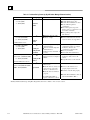
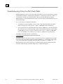
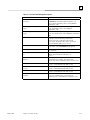
Quick Guide to the Manual
The table below provides a quick pointer into the manual for Station Manager operations. Be sure
to reference the Table of Contents and Index for more specific questions.
Questions
Where to go in the Manual
How do I connect my PC or terminal to the
Station Manager software on the Ethernet
Interface?
Chapter 2. “Accessing the Station Manager”
How to I figure out what went wrong?
How do I use the Station Manager in general?
How can I use the Station Manager to test the
Ethernet Interfaces and verify operation of the
physical network?
Chapter 3. “Troubleshooting”
Chapter 4. “How to Use the Station Manager”
Chapter 5. “Testing Ethernet Interfaces on the Network”
Where do I find descriptions of each Station
Manager Command?
Chapter 6. “Style A Command Descriptions”
-orChapter 7. “Style B Command Descriptions”
See especially the following commands:
LOG command
TALLY command
STAT command
1-2
TCP/IP Ethernet Communications Station Manager Manual – May 2002
GFK-1186G
Chapter
Accessing the Station Manager
2
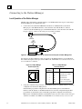
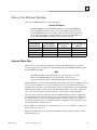
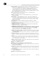
The Station Manager on the Ethernet Interface can be accessed in two* ways:
1.
Through the Station Manager serial port on the Ethernet Interface by a PC running a
terminal emulator (typically Hyperterm) or by an ASCII terminal. See Figure 2–1.
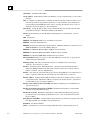
2.
Remotely over the Ethernet network via another Ethernet Interface by a PC running a
terminal emulator or by an ASCII terminal. This method requires the use of the REM
(Remote) command to access the remote station. See Figure 2–2.
a45623
Ethernet
TRANSCEIVER
RS-232
SERIAL LINK
ETHERNET
INTERFACE
STATION MANAGER
PC Running a Terminal Emulator
(or an ASCII Terminal)
SERIES 90-70 PLC
or
SERIES 90-30 PLC
Figure 2-1. Station Manager Accessed Locally through the Station Manager Port
Ethernet
TRANSCEIVER
ETHERNET
INTERFACE
RS-232
SERIAL
LINK
a45624
TRANSCEIVER
ETHERNET
INTERFACE
STATION MANAGER
STATION MANAGER
SERIES 90-70 PLC
or
SERIES 90-30 PLC
SERIES 90-70 PLC
or
SERIES 90-30 PLC
MAC Address 080019010020
IP Address 10.0.0.1
Network Address Name PLC01
Must be theREM (Remote) Command to
Station Manager via remote IP address,
Address Name, or MAC
PC Running a Terminal
(or an ASCII
Figure 2-2. Station Manager Accessed Remotely over the Network Using the REM (Remote) Command
* A third way exists for customers whose networks contain Series 90 Ethernet Interfaces (Type 1)
or Series 15/16 CNC OSI–Ethernet Interfaces. See the Terminal Emulator section later in this
chapter.
GFK-1186G
2-1
2
Connecting to the Station Manager
Local Operation of the Station Manager
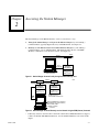
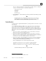
Whether using a PC running a terminal emulator or an ASCII terminal, the steps for connecting to
the Station Manager are essentially the same.
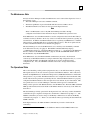
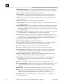
1.
Connect the serial cable IC693CBL316A from the PC or ASCII terminal to the Station
Manager port of the Ethernet Interface. The end of the cable with the RJ–11 connector
connects to the Station Manager port on the Ethernet Interface. The end of the cable with the
D–type connector connects to the serial port on your PC or terminal.
a45485
RJ-11
CONNECTOR
9-PIN
FEMALE
CONNECTOR
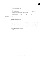
Figure 2-3. Serial Cable (IC693CBL316A) to Connect Personal Computer to Station Manager Port
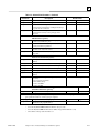
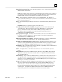
For reference, the Station Manager serial port pinouts on the Ethernet Interface are included here.
For a further description of this port, refer to GFK–1541, TCP/IP Ethernet Communications for the
Series 90 PLC User’s Manual.
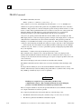
Figure 2-4. Station Manager
Serial Port (RS–232)
a45696
1
2
3
4
5
6
2.
Table 2-1. Station Manager
Serial Port Pinouts
Pin
Number
1
2
3
4
5
6
Signal
CTS
TD
SG
SG
RD
RTS
Description
Clear To Send (input)
Transmit Data (output)
Signal Ground
Signal Ground
Receive Data (input)
Request to Send (output)
Set up the communication parameters of the terminal emulator or ASCII terminal to match the
configuration for the Station Manager Port.
If the the PLC programmer configuration for the Station Manager Port of the Ethernet
Interface used the defaults, or the Ethernet Interface has not been configured using the PLC
programmer, use the default values. If the PLC programmer configuration for the Station
Manger Port of the Ethernet Interface used different values, use those values for the serial port
of the PC or terminal. See GFK–1541, TCP/IP Ethernet Communications for the Series 90
2-2
TCP/IP Ethernet Communications Station Manager Manual – May 2002
GFK-1186G
2
PLC User’s Manual for instructions on using the PLC programmer software to configure the
serial ports of the Ethernet Interface. The default configuration is:
9600 bits per second
8 data bits
No parity
1 stop bit
No flow control
3.
Press the Enter key. The Station Manager should respond with the Station Manager prompt
character ( > ).
Note
The Ethernet Interface may intermittently miss input characters at the serial port
when the module is very busy. Missed inputs are not echoed to the user. Under
these conditions, the user should verify that the input character is echoed.
Terminal Emulators
A terminal emulator is supplied with the Windows operating system that can be used to access the
Station Manager.
Also, the GEnet System Manager (GSM) software supplied with the Series 90 PLC Ethernet
Interface (Type 1) software and the Series 15/16 CNC Ethernet software contains a terminal
emulator that can be used to access the Station Manager port on the Series 90 Ethernet Interfaces.
There are three ways to use the GSM to access the Station Manager on the Series 90 Ethernet
Interface:
1.
The personal computer on which the GSM runs can be connected directly to the Station
Manager serial port on the Series 90 Ethernet Interface.
2.
The personal computer on which the GSM runs can be connected directly to the Station
Manager serial port on an Ethernet Interface. Then the REM Station Manager command can
be addressed to a remote Series 90 Ethernet Interface over the network.
3.
The personal computer on which the GSM runs can remotely access the Series 90 Ethernet
Interface over the network, using the network interface within the PC, when the GSM is
executing its Network Station Manager Terminal Feature.
Refer to the GSM chapter in any of the following manuals for details.
TCP/IP Ethernet Communications for the Series 90 PLC User’s Manual (GFK–1004 )
MMS Ethernet Communications for the Series 90 PLC User’s Manual (GFK–0868)
OSI–Ethernet Communications for Series 15 and Series 16 CNCs User’s Manual (GFK–0706)
Note
Style B Station Manager modules do not support the GSM.
GFK-1186G
Windows is a registered trademark of Microsoft, Inc.
Chapter 2 Accessing the Station Manager
2-3
2
Remote Operation of the Station Manager
The Station Manager commands can be invoked over the network from other Series 90 PLC
Ethernet Interfaces or GE Fanuc CNC OSI–Ethernet Interfaces by using the REM command. When
invoked remotely, the Station Manager software processes the command as if it had been entered
from a device attached to the serial port but automatically directs output from the command over
the LAN to the station which issued the request. There is no indication on the local Station
Manager terminal (if attached) when a remote command is being processed.
Note
Both the local and remote access share the same security level. See the LOGIN and LOGOUT
command descriptions.
Note
Style B Station Manager modules do not support the remote station manager
operation using a MAC address and thus cannot be accessed remotely from GE
Fanuc CNC OSI–Ethernet Interfaces.
2-4
TCP/IP Ethernet Communications Station Manager Manual – May 2002
GFK-1186G
Chapter
Troubleshooting
3
This chapter is a guide to troubleshooting and problem isolation for the Ethernet Interface.
The chapter covers the following topics:
GFK-1186G
Diagnostic tools available
States of the Ethernet Interface
Troubleshooting using the LEDs
Troubleshooting using the Station Manager
Troubleshooting using the PLC Fault Table
What to do if you cannot solve the problem
3-1
3
Diagnostic Tools Available for Troubleshooting
There are several tools to assist you in diagnosing problems with the Series 90 Ethernet Interface
and the network.
Use the Ethernet Interface LEDs to troubleshoot a problem on power–up of the Ethernet
Interface and for an immediate visual summary of the operational state of the Interface. Refer
to the topic, “Troubleshooting using the LEDs”, later in this chapter for more information.
Use the Series 90 PLC Fault Table to troubleshoot a problem once the Interface is running. It
provides a record of exceptions logged by the PLC, the Ethernet Interface, and other Series 90
modules. The PLC Fault Table may be accessed through the PLC Programmer software.
Look in the PLC Fault Table for a logged fault, then refer to the topic “Troubleshooting Using
the PLC Fault Table” in this chapter for instructions on what action to take.
Use the Status Data to troubleshoot ladder programs containing COMMREQ functions that
initiate communications. The status data consists primarily of the Status bits and the
Communications Status words. Refer to GFK–1541, TCP/IP Ethernet Communications for the
Series 90 PLC User’s Manual, Chapter 3, “Programming Communications Requests”, for
more information.
Use the Station Manager software to troubleshoot a problem with the Interface, with the
network, with PLC backplane communication, or with your application. The LOG, TALLY,
EXS, and STAT Station Manager commands are especially useful.
•
The LOG command provides a record of exceptions occurring with the network and
Interface.
•
The TALLY command provides statistics about operation and performance of the network
and Interface.
•
The EXS command provides information about COMMREQs.
•
The STAT command provides the current status on the operation of the Interface.
Refer to relevant chapters in this manual for information on how to access and use the Station
Manager software.
3-2
TCP/IP Ethernet Communications Station Manager Manual – May 2002
GFK-1186G
3
States of the Ethernet Interface
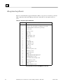
The states of the Ethernet Interface are described below.
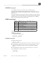
Note on LED Names
The IC693CMM321 Series 90–30 Ethernet Interfaces and the IC697CMM742
Series 90–70 Ethernet Interface (Type 2) each have 4 LEDs. The CPU364 and
CPU374 Ethernet Interfaces have 3 LEDs. Many of the functions being indicated
are the same from module-to-module, with the exception of the third LED from
the top (FDX, SER, SERIAL ACTIVE, N/A) in the following table.
LED Indicators for Ethernet Interface Products
IC693CPU364/374
IC697CMM742
AAUI-Only Type
10Base-T Type
Ethernet Interface CPUs with Ethernet
IC693CMM321
IC693CMM321
Interface
(Type 2)
Ethernet Interface Ethernet Interface
OK
OK
MODULE OK
EOK
LAN
FDX
LAN
SER
LAN ONLINE
SERIAL ACTIVE
LAN
(N/A)
STAT
STAT
STATUS
STAT
Hardware Failure State
When power is cycled on the Series 90 PLC, or whenever the Ethernet Interface is restarted,
power–up diagnostics run. Diagnostics running is indicated by the OK LED fast blinking, while
the other LEDs remain OFF.
Note
If all LEDs turn OFF and stay OFF during power–up diagnostics, or if on the
CPU374, the EOK LED blinks in a repeated sequence, then power–up
diagnostics have failed. Refer to the PLC Fault Table for more information.
The PLC Fault Table can be especially helpful in detailing faults that are detected during power–up
because the Station Manager is not operational during power-up. If the Ethernet Interface has a
problem, it may not be able to report fault details. In the case of the CPU374 only, the EOK LED
blinks a two-digit failure code that can also help determine the nature of the failure. Refer to the
topic, ”Troubleshooting Using the PLC Fault Table” in this chapter for more information.
Upon successful completion of diagnostic testing, the Ethernet Interface waits for configuration
data from the PLC CPU. This may take several seconds, depending upon the PLC configuration.
If configuration data is not received, the Ethernet Interface will use a backup copy of the most
recent valid configuration data. (Each Ethernet Interface is shipped from the factory with a valid
set of default backup configuration data.)
Refer to GFK–1541, TCP/IP Ethernet Communications for the Series 90 PLC User’s Manual for
details on the power–up process.
The Restart pushbutton is not operable during the Ethernet Interface diagnostic phase nor is the
Station Manager active.
GFK-1186G
Chapter 3 Troubleshooting
3-3
3
Software Load State
The Software Load state is automatically entered if the Power–up Diagnostics detect a problem
with the primary software. For Style A Station Manager modules, it can also be entered if the
Station Manager user issues a LOAD command or the Restart pushbutton is pressed and held until
the bottom (STAT) LED comes ON. In the Software Load state, all Ethernet Interface LEDs are
blinking in unison.
In the Software Load state, the Ethernet Interface can accept a download of its operating software
from an external PC Loader device (a PC running the PC Software Loader program). Refer to
GFK–1541, TCP/IP Ethernet Communications for the Series 90 PLC User’s Manual, Appendix C,
for a description of the software loading process. Once a software load has begun, the existing
communications software is deleted; the Ethernet Interface must be completely reloaded.
For Style A Station Manager modules, the Restart pushbutton may be used to abort the Software
Load state. If the existing operating software has not been erased or corrupted, the Ethernet
Interface will restart immediately into the Operational state upon pressing the pushbutton. If the
operating software is not available, the Ethernet Interface always restarts into the Software Load
state.
For Style B Station Manager modules, the load takes place as a part of an overall update of the PLC
CPU firmware. No separate load of the Ethernet Interface is required or supported.
Waiting for IP Address State
If a non–zero IP address for the Ethernet Interface was not configured prior to power up, or the IP
address was configured to 0.0.0.0, the Interface will wait indefinitely for a non–zero IP address.
The OK and STAT LEDs blink in unison. In this state, the Ethernet Interface does not perform any
SRTP Server or Channel API operations (or Modbus/TCP Server or Channel API operations*). If
this occurs, you need to configure a non–zero IP address using the PLC Programmer configuration
software and restart the module.
For Style A Station Manager modules, you may temporarily supply an IP address using the BOOTP
Station Manager command; an IP address supplied by a BOOTP server, or the BOOTP Station
Manager command remains effective only until the next restart of the Ethernet Interface.
For Style B Station Manager modules, you may temporarily assign an IP address over the network.
See Appendix D for the process to assign a temporary IP address to a Style B Station Manager
module.
*
3-4
Modbus/TCP available only on Series 90-30 Ethernet Interface IC693CMM321-FH or later.
TCP/IP Ethernet Communications Station Manager Manual – May 2002
GFK-1186G
3
The Maintenance State
For Style A Station Manager modules, the Maintenance state is entered after diagnostics if one of
the following occurs:
The Station Manager user issues a MAINT command,
The Restart pushbutton is pressed and held until the bottom two LEDs come on
The Ethernet Interface has detected a fatal error in the Operational state
Note
There is no Maintenance state for Style B Station Manager modules. Backup
configuration and Advanced User Parameters may be modified in the operational state.
In the Maintenance state, the Ethernet Interface uses the configuration data from the PLC CPU (if
available), but always defaults to the factory values for all Advanced User parameters, ignoring any
customizations. In addition, the Ethernet Interface does not perform any SRTP Server or Channel
API operations (or Modbus/TCP Server or Channel API operations*). This allows quick and safe
isolation of the Ethernet Interface for troubleshooting purposes.
The Station Manager is active in the Maintenance state, and always uses the Modify command
level without the necessity of logging in. The NODE command additionally displays,
“<<<Maintenance State>>>”. The Station Manager prompt is “*”. For the Series 90–30 Ethernet
Interface and Series 90–70 Ethernet Interface (Type 2), the OK and SER LEDs blink in unison.
For the CPU364, only the EOK LED blinks.
In the Maintenance state, the TEST and PING commands may be used to check network
connectivity. If this Ethernet Interface is using its internal backup configuration data (i.e., was not
configured with the PLC), the CHSOSW command may be used to modify the backup
configuration data. Also, the CHPARM command can be used to change Advanced User
Parameters.
The Operational State
This section identifies possible problem symptoms that may occur while the module is operating.
The Operational state is the state of normal operation of the Ethernet Interface. Full connection to
the PLC and full SRTP Server and Channel API operation (and Modbus/TCP Server and Channel
API operations*) are provided. The Ethernet Interface uses configuration data from the PLC CPU,
and the Advanced User parameters specified by the user. When the Ethernet Interface is properly
configured, the Ethernet Interface enters the Operational state without any user intervention. This
state permits user access to Station Manager commands at their respective command levels.
During normal operation of the Ethernet Interface, the OK LED is ON. The LAN, SER, and STAT
LEDs provide information about the health of the Ethernet Interface and activity on the LAN and
Serial Port 2.
The Station Manager is fully operational in the Operational state, and always assumes the Monitor
command level upon completion of Diagnostics; the Monitor command level prompt is “>”. The
LOGIN command may be used to change to the Modify command level as desired; the Modify
command level prompt is “=”. There is no state indication message following the Station ID in the
NODE command.
In the Operational state, the TEST and PING commands may be used to check network
connectivity.
*
GFK-1186G
Modbus/TCP available only on Series 90-30 Ethernet Interface IC693CMM321-FH or later.
Chapter 3 Troubleshooting
3-5
3
Troubleshooting Using the LEDs
Powering–up the Ethernet Interface
After configuring the Interface and storing the configuration to the PLC, follow the procedure
below to verify that the Ethernet Interface is operating correctly.
1.
Turn power OFF to the PLC for 3-5 seconds, then turn the power back ON. This will initiate
a series of diagnostic tests.
The OK LED will blink indicating the progress of power–up.
2.
The LEDs will have the following pattern upon successful power–up. At this time the Ethernet
Interface is fully operational and on–line with no exception conditions.
Note
The “SER” LED is not present on the Series 90–30 CPU364 and CPU374. Also,
this LED is labeled “SER” on AAUI-Only style IC693CMM321 and “FDX” on
the 10Base-T style IC693CMM321. Refer to ”Note on LED Names” in the
previous section ”States of the Ethernet Interface”.
LED
Status After Power-Up
• (ON)
•/∗ (ON or Blinking if Traffic is Present)
OK
LAN
SER or FDX1
ο
(OFF)
2
•
(ON)
STAT
1
The AAUI-Only type CMM321 has a SER LED; the 10Base-T type CMM321 has an
FDX LED; the CPU364 and CPU374 do not have this LED.
2
If STAT LED is OFF, check the PLC Fault Table. Alternatively, use the Station
Manager LOG command.
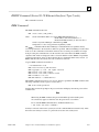
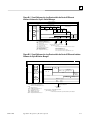
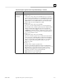
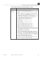
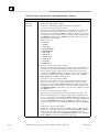
Problems During Power–up
If a problem is detected during power–up, the Ethernet Interface may not transition directly to the
Operational state. If the Interface does not transition to Operational, check the LED pattern on the
Interface and refer to Figure 3–1, 3–2 or 3-3 to find out where the Interface stopped. Refer to
Table 3–1, 3–2, or 3-3 for corrective actions.
3-6
TCP/IP Ethernet Communications Station Manager Manual – May 2002
GFK-1186G
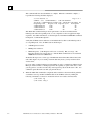
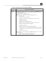
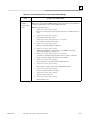
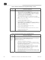
3
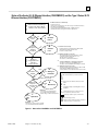
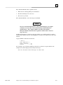
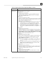
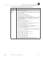
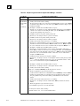
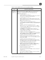
States of the Series 90–30 Ethernet Interface (IC693CMM321) and the Type 2 Series 90-70
Ethernet Interface (IC697CMM742)
Ethernet Interface Initializing 1
1
- Powering up the PLC
- Storing a new configuration to the PLC with changes for the Ethernet Interface
- Pressing the Restart pushbutton
- Issuing a Station Manager RESTART, LOAD, or MAINT command
- Internal System Error occurring when Interface is Operational
2-10 seconds, Series 90-30
10-20 seconds, Series 90-70
No
Diagnostics
Pass?
The Ethernet Interface is initialized by
A
Hardware
Failure
Yes
2
Load
Request or
Software
Corrupted?
Yes
2
B
Software
Load
3
No
C
Waiting for
Configuration from
PLC CPU
(max. 2 minutes)
4
5
Done
Yes
3
IP address =
0.0.0.0
D
z/ ∗/ Waiting for
IP Address
No
IP Address Received
5
Maintenance
Request or
Fatal System
Error?
No
z
F
z/ ∗/
z/ Operational
z/
Yes
z/ ∗/
4
E
Maintenance
z/
Maintenance
- Client and server capability disabled
- Uses default Advanced Parameters
- Permits changes to Advanced Parameters
Software Load Caused by
- Restart pushbutton pushed until bottom LED turns ON
- Station Manager LOAD command issued
- Detection of corrupt software
Waiting for IP Address Caused by
- Not configuring Interface using configuration software
- Configuring software with IP address = 0.0.0.0
- New CPU with no configuration
- CPU failure to communicate with Interface
Continue to Maintenance or Operational Caused by
- IP address received from network BOOTP server
- IP address entered by BOOTP Station Manager command
Maintenance Request Caused by
- Restart pushbutton pushed until bottom two LEDs turn ON
- Station Manager MAINT command issued
- Fatal System Error while in Operation State forced a restart
Symbols
The LEDs are labeled from top to bottom as follows:
OK
LAN
SER
STAT
The symbols used for the LEDs are defined as follows:
z
∗
= OFF
= ON
= Slow Blink; multiple slow blinking LEDs in unison
= Fast Blink
= Traffic (blinks when there is traffic on the line)
The process symbols are defined as follows:
Operational
- Full support for client and server capability
- Uses user-defined Advanced Parameters
= Temporary condition; requires no intervention
= Decision during powerup
= Interface State; normally the Interface remains in a
State unless there is user intervention
Figure 3-1. States of the IC693CMM321 and IC697CMM742
GFK-1186G
Chapter 3 Troubleshooting
3-7
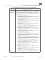
3
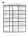
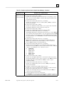
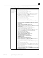
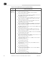
Table 3-1. Problems During Power–Up for IC693CMM321 and IC697CMM742
LED Pattern
Where Stopped
A
❍
❍
❍
❍
OK (OFF)
LAN (OFF)
FDX (OFF)
STAT (OFF)
✫
✫
✫
✫
OK (Slowblink)
LAN (Slowblink)
FDX (Slowblink)
STAT (Slowblink)
Possible Cause
Fatal Hardware Error.
Hardware
Failure
B
Software
Loader
Restart pushbutton until bottom
LED turns ON.
Station Manager LOAD
command issued.
Software corrupt.
Corrective Actions
Make sure the PLC has power.
Examine PLC Fault Table for clues.*
Recheck PLC Programmer configuration.
Power off baseplate, inspect the Interface
for loose components, reseat the Interface,
and Restart.
Try a different slot.
If the problem persists, replace the
Interface or PLC hardware.
Connect a PC Software Loader and load
new software. See Appendix C.
Cycle power or press Restart pushbutton
again for less than 5 seconds to restart the
Interface and clear the load request.
All LEDs blink in unison.
✫
❍
❍
❍
C
OK (Slowblink)
LAN (OFF)
FDX (OFF)
STAT (OFF)
Waiting for
Configuration
from PLC
Did not configure slot using
PLC Programmer.
New CPU with no
configuration.
CPU not communicating with
Ethernet Interface
(Condition can last a maximum
of 2 minutes.)
OK (Slowblink)
✫
●/∗/❍ LAN (ON/Traffic/OFF)
FDX (OFF/Slowblink)
❍
STAT (Slowblink)
✫
D
Waiting for IP
Address
Interface’s IP address has not been
configured or has been configured
as 0.0.0.0.
Use PLC Programmer configuration
software to configure the Interface then
store the configuration to the PLC CPU.
Make sure Interface is in the correct slot
on the baseplate.
Power cycle the PLC.
Clear faults and Restart Interface.
Use PLC Programmer to configure the
Interface with a non-zero IP address.
Use a BOOTP server to provide
Interface with a non-zero IP address.
OK and STAT blink in unison.
✫
●/∗/❍
✫
●/❍
OK (Slowblink)
E
LAN (ON/Traffic/OFF)
FDX (Slowblink)
STAT (ON/OFF)
Maintenance
OK and SER blink in unison.
OK (ON)
●
●/∗/❍ LAN (ON/Traffic/OFF)
●/❍ FDX (ON/OFF)1
●/❍ STAT (ON/OFF)
1
FDX should be ON if Full
Duplex mode is activated;
otherwise, it should be OFF.
F
Operational
Restart pushbutton pressed until
bottom two LEDs turn ON.
Station Manager MAINT
command issued.
Internal System Error when
Interface was Operational
caused a restart and entrance
into Maintenance.
If the LAN LED is OFF, the
problem may be:
Network cable or transceiver
not connected to Interface or
bad transceiver.
Network cable not terminated
properly.
SQE not enabled on
transceiver.
If the STAT LED is OFF, an
exception condition has
occurred.
If you did not intend to enter
Maintenance press the Restart pushbutton
for less than 5 seconds. This clears the
Maintenance request.
Examine PLC Fault Table for clues.*
If you need to use the Station Manager to
troubleshoot a problem, see GFK-1186,
TCP/IP Ethernet Communications for the
Series 90 PLC Station Manager Manual.
Connect cable and transceiver properly.
Replace transceiver.
Terminate network cable properly.
Set SQE ON on transceiver in accord with
manufacturer’s instructions.
Examine PLC Fault Table to find out why
the STAT LED is OFF. *
*Identify the PLC fault message using PLC Programmer, then refer to Table 3–4 for corrective actions.
3-8
TCP/IP Ethernet Communications Station Manager Manual – May 2002
GFK-1186G
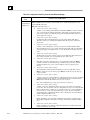
3
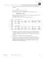
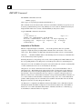
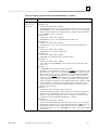
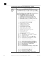
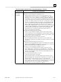
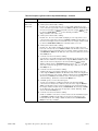
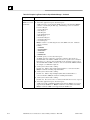
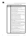
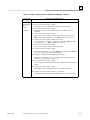
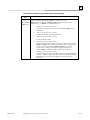
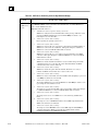
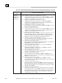
States of the Series 90–30 CPU364 Ethernet Interface
1 The Ethernet Interface is initialized by
- Powering-up the PLC
- Storing a new configuration to the PLC with changes for the Ethernet Interface
- Pressing the Restart pushbutton
- Issuing a Station Manager RESTART, LOAD, or MAINT command
- Internal System Error occurring when Interface is Operational
Ethernet Interface
Initializing 1
(approx. 2-6 seconds)
No
Diagnostics
Pass?
A
Hardware
Failure
Software
Load
Yes
Load
Request or
Software
Corrupted?
Yes
2
B
No
2 Software Load Caused by
- Restart pushbutton pushed until bottom LED turns ON
- Station Manager LOAD command issued
- Detection of corrupt software
3
Waiting for IP Address Caused by
- Not configuring Interface using configuration software
- Configuring Interface with IP address = 0.0.0.0
- New CPU with no configuration
- CPU failure to communicate with Interface
4
Continue to Maintenance or Operational Caused by
- IP address received from network BOOTP server
- IP address entered by BOOTP Station Manager command
5
Maintenance Request Caused by
- Restart pushbutton pushed until bottom two LEDs turn ON
- Station Manager MAINT command issued
- Fatal System Error while in Operational State forced a restart
C
Waiting for
Configuration from
PLC CPU
(max. 2 seconds)
Done
Yes
3
IP address =
0.0.0.0
D
z/ ∗/ Waiting for
IP Address
No
IP Address Received
4
Symbols
The LEDs are labeled from top to bottom as follows:
EOK
LAN
STAT
The symbols used for the LEDs are defined as follows:
Maintenance
Request or
Fatal System
Error?
No
z
Yes5
z/ ∗/
z/
E
Maintenance
Maintenance
- Client and server capability disabled
- Uses default Advanced Parameters
- Permits changes to Advanced Parameters
F
z/ ∗/ Operational
z/
= OFF
z
= ON
= Slow Blink; multiple slow blining LEDs blink in unison
= Fast Blink
∗
= Traffic (blinks when there is traffic on the line)
The process symbols are defined as follows:
= Temporary condition; requires no intervention
= Decision point during power-up
= Interface State; normally the Interface remains
in a State unless there is user intervention
Operational
- Full support for client and server capability
- Uses user defined Advanced Parameters
Figure 3-2. States of the Series 90–30 CPU364 Ethernet Interface
GFK-1186G
Chapter 3 Troubleshooting
3-9
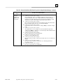
3
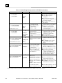
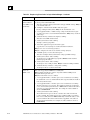
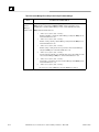
Table 3-2. Problems During Power–Up (Series 90–30 CPU364 Ethernet Interface)
LED Pattern
❍ EOK (OFF)
❍ LAN (OFF)
❍ STAT (OFF)
✫ EOK (Slowblink)
✫ LAN (Slowblink)
✫ STAT (Slowblink)
All LEDs blink in unison.
✫ EOK (Slowblink)
❍ LAN (OFF)
❍ STAT (OFF)
Where Stopped
A
● EOK (ON)
●/✲/❍ LAN (ON/Traffic/OFF)
●/❍ STAT(ON/OFF)
Fatal Hardware Error.
Hardware
Failure
B
Software
Loader
C
Waiting for
Configuration
from PLC
✫ EOK (Slowblink)
D
●/✲/❍ LAN (ON/Traffic/OFF)
✫ STAT (Slowblink)
Waiting for IP
Address
EOK and STAT blink in unison.
✫ EOK (Slowblink)
●/✲/❍ LAN (ON/Traffic/OFF)
●/❍ STAT(ON/OFF)
Possible Cause
E
Maintenance
F
Operational
Restart pushbutton until the
bottom LED turns ON.
Station Manager LOAD
command issued.
Software corrupt.
Did not configure slot using the
PLC Programmer.
CPU not communicating with
Ethernet Interface.
(Condition can last a maximum of
2 seconds.)
Interface’s IP address has not been
configured or has been configured
as 0.0.0.0.
Corrective Actions
Make sure the PLC has power.
Examine PLC Fault Table for clues.*
Recheck PLC Programmer
configuration.
Power off baseplate, inspect the
Interface for loose components, reseat
the module, and Restart.
If the problem persists, replace the
PLC hardware.
Connect a PC Software Loader and
load new software. See Appendix C.
Cycle power or press Restart
pushbutton again for less than 5
seconds to restart the Interface and
clear the load request.
Use the PLC Programmer
configuration software to configure
the Interface then store the
configuration to the PLC CPU.
Power cycle the PLC.
Clear faults and Restart Interface.
Use the PLC Programmer to configure
the Interface with a non-zero IP
address.
Use a BOOTP server to provide
Interface with a non-zero IP
address.
Restart pushbutton until the
bottom two LEDs turn ON.
Station Manager MAINT
command issued.
Internal System Error when
Interface was Operational
caused a restart and entrance
into Maintenance.
If the LAN LED is OFF, the
problem may be:
Network cable not connected or
transceiver not connected to
Interface or bad transceiver.
Network cable not terminated
properly.
SQE not enabled on transceiver.
If the STAT LED is OFF, an
exception condition has occurred.
If you did not intend to enter
Maintenance press the Restart
pushbutton for less than 5 seconds.
This clears the Maintenance request.
Examine PLC Fault Table for clues.*
If you need to use the Station
Manager to troubleshoot a problem,
see GFK-1186, TCP/IP Ethernet
Communications for the Series 90
PLC Station Manager Manual.
Connect cable and transceiver
properly. Replace transceiver.
Terminate network cable properly.
Set SQE ON on transceiver in accord
with manufacturer’s instructions.
Examine PLC Fault Table to find out
why the STAT LED is OFF. *
*Identify the PLC fault message using PLC Programmer, then refer to Table 3–4 for corrective actions.
3-10
TCP/IP Ethernet Communications Station Manager Manual – May 2002
GFK-1186G
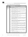
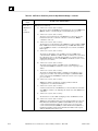
3
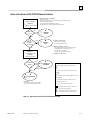
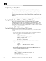
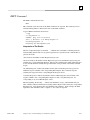
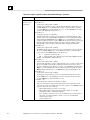
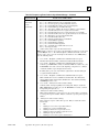
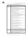
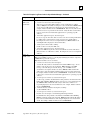
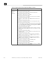
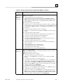
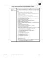
States of the Series 90-30 CPU374 Ethernet Interface
1 The Ethernet Interface is initialized by
- Powering-up the PLC
- Storing a new configuration to the PLC with changes for the Ethernet Interface
- Pressing the Restart pushbutton
- Issuing a Station Manager RESTART command
- Internal System Error occurring when Interface is Operational
Ethernet Interface
Initializing 1
(approx. 2-6 seconds)
No
Diagnostics
Pass?
A
Hardware
Failure
Software
Load
Yes
Load
Request or
Software
Corrupted?
Yes
2
B
- Detection of corrupt software
- Load request from Win Loader
3
No
2 Software Load Caused by
C
Waiting for
Configuration from
PLC CPU
(max. 2 seconds)
4
Waiting for IP Address Caused by
- Not configuring Interface using configuration software
- Configuring Interface with IP address = 0.0.0.0
- New CPU with no configuration
- CPU failure to communicate with Interface
IP Address set over network
Done
Yes
3
IP address =
0.0.0.0
D
z/ ∗/ Waiting for
IP Address
No
IP Address Received
4
Symbols
The LEDs are labeled from top to bottom as follows:
EOK
LAN
STAT
The symbols used for the LEDs are defined as follows:
= OFF
z
E
z/ ∗/ Operational
z/
Operational
- Full support for client and server capability
- Uses user defined Advanced Parameters
z
= ON
= Slow Blink; multiple slow blining LEDs blink in unison
= Fast Blink
∗ = Traffic (blinks when there is traffic on the line)
= Blinking an error code
The process symbols are defined as follows:
= Temporary condition; requires no intervention
= Decision point during power-up
= Interface State; normally the Interface remains
in a State unless there is user intervention
Figure 3-3. States of the Series 90–30 CPU374 Ethernet Interface
GFK-1186G
Chapter 3 Troubleshooting
3-11
3
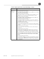
Table 3-3. Problems During Power–Up (Style B Station Manager Ethernet Interface)
LED Pattern
EOK (OFF)
❍ LAN (OFF)
❍ STAT (OFF)
✫ EOK (Slowblink)
✫ LAN (Slowblink)
✫ STAT (Slowblink)
All LEDs blink in unison.
✫ EOK (Slowblink)
❍ LAN (OFF)
❍ STAT (OFF)
Where Stopped
A
Fatal Hardware Error.
Hardware
Failure
B
Winloader attached to CPU
Software corrupt.
Software
Loader
C
Waiting for
Configuration
from PLC
✫ EOK (Slowblink)
D
●/✲/❍ LAN (ON/Traffic/OFF)
✫ STAT (Slowblink)
Waiting for IP
Address
EOK and STAT blink in unison.
● EOK (ON)
●/✲/❍ LAN (ON/Traffic/OFF)
●/❍ STAT(ON/OFF)
Possible Cause
E
Operational
Did not configure slot using the
PLC Programmer.
CPU not communicating with
Ethernet Interface.
(Condition can last a maximum of
2 seconds.)
Interface’s IP address has not been
configured or has been configured
as 0.0.0.0.
If the LAN LED is OFF, the
problem may be:
Network cable not connected or
transceiver not connected to
Interface or bad transceiver.
Network cable not terminated
properly.
If the STAT LED is OFF, an
exception condition has occurred.
Corrective Actions
Make sure the PLC has power.
Examine blink code for clues.
Examine PLC Fault Table for clues.*
Recheck PLC Programmer
configuration.
Power off baseplate, inspect the
Interface for loose components, reseat
the module, and Restart.
If the problem persists, replace the
PLC hardware.
Connect a PC Software Loader and
load new software. See Appendix C.
Use the PLC Programmer
configuration software to configure
the Interface then store the
configuration to the PLC CPU.
Power cycle the PLC.
Clear faults and Restart Interface.
Use the PLC Programmer to configure
the Interface with a non-zero IP
address.
Assign IP address over the network.
Connect cable and transceiver
properly. Replace transceiver.
Terminate network cable properly.
Examine PLC Fault Table to find out
why the STAT LED is OFF. *
*Identify the PLC fault message using PLC Programmer, then refer to Table 3–4 for corrective actions.
3-12
TCP/IP Ethernet Communications Station Manager Manual – May 2002
GFK-1186G
3
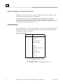
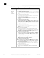
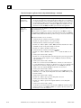
Troubleshooting Using the Station Manager
The Station Manager provides interactive commands that can be used to troubleshoot the Ethernet
Interface. There are two types of commands: monitor commands and modify commands. The
monitor commands allow you to observe internal statistics, the contents of an exception log, and
configuration parameter values. The modify commands allow you to clear the statistics and the log,
and to change parameter values. The Station Manager commands are discussed in detail in Chapter
6/7, “Command Descriptions”.
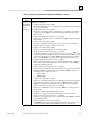
Within the Ethernet Interface software are various tasks, each of which performs a specific
function. For example, the TCP task performs the TCP protocol functions. Many Station Manager
commands allow you to access information about one or more specific task at a time.
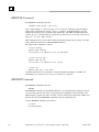
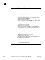
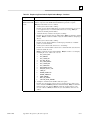
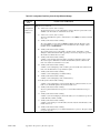
Tasks for Modules Using Style A Station Manager
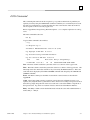
The figure below provides a visual reference for the various tasks within the Ethernet Interface
software.
Series 90-70/30 PLC
Backplane
PLC Backplane Driver
(c) [08]
*
System
(b) [02]
PLC
CPU
Software
Loader
Modbus/TCP
Server
(s) [1f]
Station
Manager
4
4
Modbus/TCP
Channel API
(m) [1e]
TCP
(w) [12]
SRTP
Server
(v) [1b]
Channel
API
(h) [1c]
Ethernet Interface
EGD 1, 3
(g) [28]
Naming
Services
(r) [27]
1, 3
SNTP
[29]
BOOTP
[21]
REM
Station Mgr
Command
PING
Station Mgr
Command
UDP (u)
Powerup
Diagnostics
[01]
IP (i) [11]
ICMP (j) [18]
IGMP1, 3 (j) [1d]
Ethernet LLC (l) [0c]
REM
TEST
Station Mgr Station Mgr
ARP (f) [16] Command Command
802.3 LLC (I) [Oc]
MAC (l) [0c]
SRTP
TCP
ICMP
IGMP
IP
ARP
LLC
MAC
AAUI
AUI
EGD
SNTP
AUI31, 2
1, 3
= Service Request Transfer Protocol
10Base2 3
10BaseT
AAUI
= Transmission Control Protocol
Tx
= Internet Control Message Protocol
10Base2
10BaseT
= Internet Group Management Protocol
Network
Network
= Internet Protocol
Network
= Address Resolution Protocol
(lower case letter) = Station Manager Task ID
= Logical Link Control
[hex numbers] = Log Event
= Media Access Control
* = Data may flow between the system task and any other function
= Apple Attachment Unit Interface
1. Series 90–30 CPU364
= Attachment Unit Interface
2. Series 90–30 Ethernet Interface
= Ethernet Global Data
3. Series 90–70 Ethernet Interface (Type 2)
= Simple Network Time Protocol
4. Series 90-30 Ethernet Interface, IC693CMM321-FG or later.
Figure 3-4. Visual Reference for Tasks within the Series 90 Ethernet Interface Software
GFK-1186G
Chapter 3 Troubleshooting
3-13
3
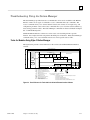
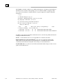
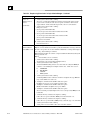
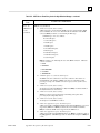
Tasks for Modules Using Style B Station Manager
The figure below provides a visual reference for the various tasks within the Ethernet Interface
software for modules using a Style B Station Manager.
Series 90-30 PLC
PLC Backplane Driver (c) [08]
*
System
(b) [02]
SRTP Server (v) [1b]
EGD
( g ) [ 28 ]
SNTP (n) [29]
PLC CPU
Software
Loader
Station
Manager
TCP
(w)
SRTP
TCP
ICMP
IP
ARP
LLC
MAC
EGD
SNTP
PING Station
Manager
Command
UDP
IP (i)
Power-up
Diagnostics
[01]
REM Station
Manager Cmd
ICMP (j)
ARP (f)
Ethernet LLC (l) [0c]
MAC
(l) [0c]
Switch
(l) [0c]
= Service Request Transfer Protocol
10Base-T/100Base-TX
= Transmission Control Protocol
= Internet Control Message Protocol
10/100 Ethernet
= Internet Protocol
Network
= Address Resolution Protocol
= Logical Link Control
(lower case letter) = Station Manager Task ID
= Media Access Control
[hex numbers] = Log Event
= Ethernet Global Data
* = Data may flow between the system task and any other function
= Simple Network Time Protocol
Figure 3-5. Tasks for Modules Using Style B Station Manager
3-14
TCP/IP Ethernet Communications Station Manager Manual – May 2002
GFK-1186G
3
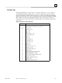
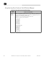
Exception Log
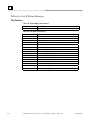
When the Ethernet Interface software detects a very unusual condition-an exception condition, it
records information about the condition in its exception log. The exception log can be viewed
using the Station Manager LOG command. Exception log contents are retained when the Ethernet
Interface restarts (in most cases), and are cleared when the user issues the Station Manager CLEAR
LOG command. (For the Series 90–30 Ethernet Interface only, the exception log contents are
cleared when power is cycled). Each task uses a unique numeric code to identify its entries in the
exception log.
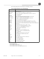
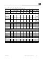
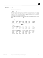
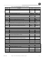
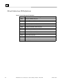
Table 3-4. Exception Log Event Definitions
Log Event
1
2 and 3
8
c
d
e
f
11
12
13
14
15
16
18
1a
1b
1c
1d
1e
1f
26
27
28
29
2a
GFK-1186G
Cause
Power up. A log entry of this event will appear every time the
Ethernet Interface is Restarted or powered up.
System events
PLC driver events
LLC events
ERR events
Station manager events
Common utility events
IP events
TCP events
Toolkit XTI events
Toolkit shell events
Toolkit user events
ARP events
ICMP events
Application specific events
SRTP Server events
SRTP Channel API events
IGMP events
Modbus/TCP Channel API events
Modbus/TCP Server events
Non–volatile memory backup events
Naming Services events
Ethernet Global Data events
SNTP events
Runtime diagnostic events
Chapter 3 Troubleshooting
3-15
3
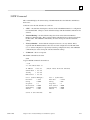
When the STAT LED is OFF
If the Ethernet Interface is in the Operational or the Maintenance state and the STAT LED is OFF,
then the Ethernet Interface has detected an exception condition and has made an entry in the
Exception Log. Each new (not repeating) log event is also sent to the PLC Fault Table, where it
can be viewed using the PLC Programmer. Refer to Appendix B, “Exception Log Event
Descriptions” for a list of possible log events.
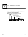
Log events are entered in the Exception Log from top to bottom, with the latest event being
identified by “->”. If the Exception Log becomes full, wrap around will occur back to the top of
the Log with the entry of new log events.
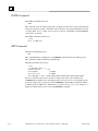
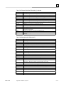
The format of a log event as displayed by the Station Manager LOG command is shown below:
Date
dd–mmm–yyyy
Time
hh:mm:ss.s
Event
xx
Count
xxxx
Entry
1
2
3
4
5
6
xx
xxxx xxxx xxxx xxxx xxxx
Date – The Date column contains the system date of the last occurrence of the logged event.
Time – The Time column contains the system time of the last occurrence of the logged event.
Event – The Event column gives the kind of event which occurred.
Count – The Count column contains a repetition count for the event. If events which are identical
occur regularly, they might otherwise flood the log with useless entries. Instead of recording each
repeated event in detail, the log simply keeps the time of the latest event and a count of the number
of repetitions of the repeated event. Log entries are generally retained on restart and reloads of the
Ethernet Interface.
Entry – The Entry columns contain detailed information about the event and is subdivided into 6
entries, Entry 1 – Entry 6.
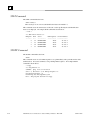
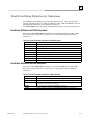
For Style B Station Manager modules, extended information is available in the log. This
information can be displayed by using the “LOG Z” command. When the “Z” option is entered,
the log command produces 132 columns of output; so an appropriate terminal or terminal emulator
should be used. In addition to the information displayed in the log command, the following
additional information is displayed.
3-16
S-Code. A 32-bit internal status code. See Appendix E for a description of the S-Code format
and values.
Remote IP Addr. Port or Produced IP Exchg. For some errors, this field contains the IP
address and port of the remote node associated with the error. For EGD, this field sometimes
contains the Producer ID and Exchange ID of the exchange associated with the error.
Local IP Addr. Port. For some errors, this field contains the IP Address and Port of the local
end point associated with the error.
TCP/IP Ethernet Communications Station Manager Manual – May 2002
GFK-1186G
3
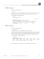
Furthermore, if the LAN LED is OFF, this indicates that an attempt to send a frame resulted in a
local fault indication. This usually results from a hardware problem. If this occurs, follow the
procedure below.
1.
Check to be sure that the cables are securely fastened to the Ethernet Interface connector and to
the transceiver (if used).
2.
Make sure the transceiver (if used) is securely fastened to the Ethernet network trunk cable.
3.
Issue a TALLY L Station Manager. If either the MacErr or the SQEErr tally is non–zero, the
local station may be experiencing an unstable network. In this case follow the procedure
below.
If this station is the only one experiencing problems:
1.
Verify that the SQE test is enabled on the transceiver connected to the Ethernet Interface.
2.
Re–tighten all transceiver cable and network connections.
3.
Make sure the Interface is seated and secured properly.
4.
Replace the transceiver cable with a known good cable.
5.
Verify that the Series 90 PLC power supply is properly grounded.
6.
If using an external transceiver, replace the transceiver with a known good transceiver.
If all stations are experiencing the problem, the cable plant is probably at fault. Re-certify the
cable plant.
When the STAT LED is ON
Sometimes problems can occur even when the STAT LED is ON, indicating normal operation. In
this case, check if the LAN LED is also ON, indicating that the Interface is successfully attached to
the Ethernet network, but there is no network activity.
To verify that the Ethernet Interface can access the PLC, issue successive TALLY C Station
Manager commands. If the PlcSweep tally is not increasing, there are no windows being provided
by the PLC. If any of the tallies PlcAbt, MyAbt, or Timeout are incrementing, there may be a
hardware problem with the Series 90 PLC backplane interface. Check the PLC Fault Table for
entries for the Ethernet Interface.
GFK-1186G
Chapter 3 Troubleshooting
3-17
3
Troubleshooting Using the PLC Fault Table
The PLC Fault Table can be accessed via the PLC Programmer. If you are experiencing a problem
with the Ethernet Interface, check the PLC Fault Table for a fault message, then refer to Table 3–4
for instructions on what to do about the problem. The relation of the fault message with the
Ethernet Interface can be determined by the rack/slot reference displayed with the fault message in
the PLC Fault Table.
To access the details of a PLC Fault Table Entry:
For Windows–based programming software, double–click on the Fault Table entry and the
details are displayed as “fault extra data”. Refer to Online Help for more information.
For Logicmaster 90, select the Fault Table entry and press <CTRL–F> to view the fault details.
The “fault extra data” are the long strings of digits on the right half of the message line. Refer
to GFK–0265, Logicmaster 90–70 Programming Software Reference Manual or GFK–0467,
Series 90–30/20/Micro Programming Software Reference Manual, for more information.
An example of the fault extra data is shown below:
160006000300050000000000000000000000000000000000
For Ethernet Interfaces the leftmost 14 digits of the the fault extra data (underlined in the example
above) show the corresponding log Events (2 digits) and Entries 2, 3, and 4 (in that order, 4 digits
each). The example above is reporting an Event 16, Entry 2=6, Entry 3=3, and Entry 4=5.
This information can be used to refer directly to detailed fault descriptions included in the LOG
event table under the LOG command in Chapter 6/7, “Command Descriptions”.
3-18
TCP/IP Ethernet Communications Station Manager Manual – May 2002
GFK-1186G
3
Table 3-5. PLC Fault Table Message Descriptions
PLC Fault Message
User Action
Backplane communications with PLC fault;
lost request
User Action: Check to make sure you are not sending
COMMREQs faster than the Ethernet Interface can
process them. If problem persists, contact GE Fanuc
Automation – NA.
Bad local application request; discarded
User Action: Check for valid COMMREQ command
request
code. If problem persists, contact GE Fanuc
Automation – NA.
Bad remote application request; discarded
User Action: Try to validate the operation of the remote
request
node. If problem persists, contact GE Fanuc Automation NA.
Can’t locate remote node; discarded request
Error reported when remote IP/MAC address
cannot be resolved. Error may indicate that
remote host is not operational on the network.
User Action: Check that remote host is operational
on network and its addresses are correct.
Message from PLC for unknown Ethernet Interface task.
Comm_req – Bad task ID programmed
User Action: Check COMMREQ function block.
Comm_req – Wait mode not allowed
User Action: Check COMMREQ to make sure sent in
no–wait mode.
Config’d gateway addr bad; can’t talk off local Error in configuration. Verify IP address, Subnetwork
net
Mask, and default Gateway IP address are
correct.
Connection to remote node failed; resuming
without it
Underlying communications software detects error
transferring data; resuming. If persistent error,
check connection to LAN and operation of remote node.
LAN controller fault; restart LAN I/F
User Action: HW fault, perform power cycle. If problem
persists, contact GE Fanuc Automation – NA.
LAN controller Tx underflow; attempt
recovery
LAN controller underrun/overrun; resuming
Internal system error. User Action: If problem
persists, contact GE Fanuc Automation – NA.
Internal system error. User Action: If problem
persists, contact GE Fanuc Automation – NA.
The Ethernet Interface does not have free memory
to process communications. User Action: If
problem persists, contact GE Fanuc Automation – NA.
LAN data memory exhausted – check parms;
resuming
GFK-1186G
Chapter 3 Troubleshooting
3-19
3
Table 4-4. PLC Fault Table Message Descriptions (Continued)
PLC Fault Message
LAN duplicate MAC Address; resuming
LAN controller fuse blown; off network
LAN I/F can’t init – check parms; running
soft Sw utl
LAN I/F capacity exceeded; discarded request
LAN interface hardware failure; switched off
network
LAN network problem exists; performance
degraded
LAN severe network problem; attempting
recovery
User Action
A frame was received in which the source MAC
Address was the same as this station’s MAC
Address. All stations on a network must have a unique MAC
address. Immediately isolate the
offending station; it may be necessary to turn it
off or disconnect it from the network. This station remains
Online unless you intervene to take it Offline.
(Series 90–70 Ethernet Interface (Type 2) and Series 90–30
PLC CPU364) The network port fuse is blown; port is
unusable. Isolate and correct the cause of the problem, and
then replace the fuse or the Ethernet Interface. Refer to GFK–
1541 for fuse type and replacement procedures.
Internal system error. User Action: If problem
persists, contact GE Fanuc Automation – NA.
Verify that connection limits are not being exceeded.
User Action: Replace Ethernet Interface.
Excessive backlog of transmission requests due to excessive
traffic on the network. For a sustained period the MAC was
unable to send frames as quickly as requested. User Action: If
problem persists, contact GE Fanuc Automation – NA.
External condition prevented transmission of frame in
specified timeframe. Could be busy network or network
problem. User Action: Check transceiver to make sure it is
securely attached to the network. Check for unterminated
trunk cable.
LAN system–software fault; aborted
connection resuming
LAN system–software fault; restarted LAN
I/F
LAN system–software fault; resuming
Internal system error. User Action: If problem
persists, contact GE Fanuc Automation – NA.
Internal system error. User Action: If problem
persists, contact GE Fanuc Automation – NA.
Internal system error. User Action: If problem
persists, contact GE Fanuc Automation – NA.
LAN transceiver fault; OFF network until
Transceiver or transceiver cable failed or became
fixed
disconnected. User Action: Reattach the cable or replace the
transceiver cable. Check SQE test switch if present on
transceiver.
Local request to send was rejected; discarded Internal error. Check that the Ethernet Interface is online. User
request
Action: If problem persists, contact GE Fanuc Automation –
NA.
Memory backup fault; may lose config/log on Internal error accessing FLASH device.
restart
User Action: If problem persists, contact GE Fanuc
Automation – NA. Replace Ethernet Interface.
Module software corrupted; requesting reload Catastrophic internal system error. Contact GE
Fanuc Automation – NA.
Module state doesn’t permit Comm_Req;
discarded
Unsupported feature in configuration
3-20
COMMREQ received when Ethernet Interface cannot process
COMMREQ. User Action: Make sure Ethernet Interface is
configured and online.
PLC firmware does not support Ethernet communications software. User Action: Check CPU
revision, order upgrade kit for CPU.
TCP/IP Ethernet Communications Station Manager Manual – May 2002
GFK-1186G
3
What to do if you Cannot Solve the Problem
If, after using the troubleshooting guide, you still cannot solve your problem, call GE Fanuc
Automation – NA. Please have the following information available when you call.
GFK-1186G
The Name and Catalog Number marked on the product (label on the outside of the side wall of
the Interface cover).
Description of symptoms of problem. Depending on the problem–you may also be asked for
the following information:
The ladder logic application program and the PLC sweep time at the time the problem
occurred.
A listing of the configuration parameters for the Ethernet Interface that failed.
A description of the network configuration. This should include the following:
The number of PLCs and host computers accessing the network
The type of network cable used (for example, twisted pair, fiber optic, etc.)
The length of network cable
The manufacturer and quantity of transceivers, hubs, and network switches used
Chapter 3 Troubleshooting
3-21
Chapter
How to use the Station Manager
4
This chapter describes the two types of Station Manager commands, monitor and modify
commands, and general rules for using them. Also discussed are the various states of the Ethernet
Interface and how the Station Manager operates in each state.
Note
The Station Manager is a “background” task. It only executes when
communication processing is not occurring. Because of this, the command
response time is sensitive to the communication load of the Ethernet Interface—
the greater the load, the longer it takes for the commands to execute. Under
extremely high load conditions, this can include the loss of input or output
characters, especially when using a serial connection to the Station Manager.
Under extreme load, you may find the Station Manager unable to process
commands until the load is removed.
Station Manager Security
The Station Manager commands are divided into two groups:
Monitor commands
Modify commands
The Monitor commands provide information about the Ethernet Interface and the network.
Executing these commands will not affect the operation of the Ethernet Interface or the network,
and they are available to anyone using the Station Manager. See Table 4–1 for a list of Monitor
commands.
The Modify commands perform functions that may change the operation of the Ethernet Interface
and the network. These commands are secure and may only be executed when the secure level of
operation has been selected by “logging in” with the current password or while in the Maintenance
state. These commands will be printed in italics in this manual. See the LOGIN command
description, and see Table 4–2 for a list of Modify commands.
GFK-1186G
4-1
4
Using the Monitor Commands
All of the Monitor commands can be executed from either the Monitor “>” prompt or the Modify
“=” prompt. To display a list of the Monitor commands on the screen, type:
> HELP
> ?
<RET>
or
<RET>
Table 4-1. Monitor Commands for a Style A Station Manager
Command
?
CHANNEL
DATE
EXS
HELP
LOG
LOGIN
LTIME
MYNAME
NAMETBL
NODE
PARM
PROG
RDNIP
Display the main PLC logic program name
2
This command is reserved
ROUTETBL
1, 2
1, 2
SNTP
SOSW
STAT
TALLY
TIME
XCHANGE
2
4-2
Display routing information
Display SNTP time synchronization information
Display current Soft Switch configuration data
Display task(s) status
Display task(s) tallies
Display current time of day
UDIS
1
Description
Display list of commands
Display the status of a communication channel
Display current date
Display Extended Status buffer
Display list of commands
Display Exception log
Login to Modify mode
Display login timeout
Display Network Address Name
Display Name Table
Display node identification message
Display a set of advanced user parameters
Reserved on all Ethernet Interfaces
1, 2
Display the status of an Ethernet Global Data exchange
Series 90–30 CPU364 only
Series 90–70 Ethernet Interface (Type 2) only
TCP/IP Ethernet Communications Station Manager Manual – May 2002
GFK-1186G
4
Table 4-2. Monitor Commands for a Style B Station Manager
Command
Description
?
EGDREAD
HELP
LOG
LOGIN
LTIME
NODE
PARM
PLCREAD
Display list of commands
Display contents of an EGD exchange
Display list of commands
Display Exception log
Login to Modify mode
Display login timeout
Display node identification message
Display a set of advanced user parameters
Display contents of PLC memory
PROG
SOSW
STAT
TALLY
TIME
Display the main PLC logic program name
Display current Soft Switch configuration data
Display task(s) status
Display task(s) tallies
Display current time of day
XCHANGE
Display the status of an Ethernet Global Data exchange
For most commands, simply enter the command and press Enter. Some commands require
additional information to be entered along with the command. Those arguments should be
separated from the command and from each other by one or more spaces. The Command
Descriptions section in this chapter provides a complete description of each command.
The LOGIN command is required to access the Modify commands. To execute the LOGIN
command, you must know the current password.
Useful Monitor Commands for Network Troubleshooting
There are three Monitor commands that are especially useful to troubleshoot the network:
The NODE command
The LOG command
The TALLY command
NODE Command: Displays the TCP/IP Ethernet sign–on message, identifying the node by its
MAC and IP addresses and identifying the resident software version number.
LOG Command: Displays a log of exception conditions (events) occurring at the local node.
The events are counted, time stamped, and differentiated by an error code.
TALLY Command: Displays counts of transactions of the specific tasks.
GFK-1186G
Chapter 4 How to use the Station Manager
4-3
4
Using the Modify Commands
To use any of the Modify commands you must obtain the modify “=” prompt using the LOGIN
command. To do this you must know the current password. The default password is “system”
(lower case characters). If you want to change the password or if you have forgotten the password
when using a Style A Station Manager, follow the appropriate procedure under the CHPARM
STPASSWD command in Chapter 6/7, “Command Descriptions.” For modules using the Style B
Station Manager, use the AUP file.
To log in, type from the “>” prompt:
LOGIN
<RET>
The password prompt will then be displayed.
Password:
Type in the current password and press Enter. If the entered password matches the current password
for the station, the modify “=” prompt is displayed. The password is case sensitive and special
characters such as “backspace” will become part of the password.
One may execute all Monitor and Modify commands (with the exception of the CHPARM and
CHSOSW commands) from the Modify “=” prompt. The CHPARM and CHSOSW commands can
be executed only
in the Maintenance state for modules using the Style A Station Manager
in the absence of a configuration from the PLC.
If no commands are executed within 10 minutes, the Modify login will time–out and you will have
to login again. This 10 minute timeout between commands can be changed if desired by using the
CHLTIME command.
Note
The security feature is intended to prevent inadvertent misuse of the Modify
commands. It is not a foolproof mechanism to prevent unauthorized changes.
For the greatest protection, restrict the number of people who know the
password, restrict access to the Station Manager terminal, and always log off
when you leave the Station Manager.
To list the Monitor commands and Modify commands on the screen, type:
HELP
?
4-4
<RET>
or
<RET>
TCP/IP Ethernet Communications Station Manager Manual – May 2002
GFK-1186G
4
The following table provides a brief description of the Modify commands.
Table 4-3. Modify Commands for a Style A Station Manager
Command
BOOTP
BROWSEDDP
CHDATE
CHLTIME
CHMYNAME +2
CHNAMETBL +2
CHPARM +
CHSNTP1, 3
CHSOSW+
CHTIME
CLEAR
KILLMS4
KILLSS
LOAD
LOGOUT
MAINT
NET
OK
PING
REM
REPORT
REPP
RESOLVE
RESTART
STOPP
STOPT
TEST
TRACE
+
1
2
3
4
GFK-1186G
Description
Supply temporary configuration parameters (Not recommended if PLC CPU is
configured properly.)
Display names defined in the DDP Directory Information Base
Change date (Not recommended if Ethernet Interface obtains correct date and
time from the PLC CPU.)
Change login timeout
Change or create Network Address Name (Not permitted if the Network
Address Name is configured at the PLC Programmer)
Add, change, or delete entries in the Name Table (Not permitted if the
Name Table is configured at the PLC Programmer)
Change a specified advanced user parameter
Temporarily override automatic SNTP time synchronization server selection
Change Soft Switch data (Not recommended if PLC CPU is configured properly.)
Change time (Not recommended if Ethernet Interface obtains correct date and time from
the PLC CPU)
Clear Extended Status buffer, Error Log,Tallies, or Heap
Delete and close a specified Modbus/TCP Server connection
Delete and close a specified SRTP Server connection
Force Ethernet Interface software update
Exit modify mode
Restart the Interface and enter the Maintenance state
Disable/Enable network access at this Ethernet Interface
Turns on STAT LED
Sends ICMP echo request messages to remote station
Send Station Manager command to remote station
Report test results
Report ping results
Resolve a Network Address Name into an IP address
Restart the Ethernet Interface
Stop an active PING command
Stop an active TEST command
Send test frames to remote station(s)
Turn on specific task trace flags
The Ethernet Interface must be in the Maintenance state to execute this command.
Series 90–30 CPU364 only
Series 90–30 Ethernet Interface only
Series 90–70 Ethernet Interface (Type 2) only
Series 90–30 Ethernet Interface IC639CMM321-FH or later only
Chapter 4 How to use the Station Manager
4-5
4
Table 4-4. Modify Commands for Style B Station Manager
Command
CLEAR
EGDWRITE
Change login timeout
Change a specified advanced user parameter
Change Soft Switch data (Not recommended if PLC CPU is configured properly.)
Change date and time (Not recommended if Ethernet Interface obtains correct date and
time from the PLC CPU)
Clear Error Log or Tallies
Modify and EGD exchange
KILLSS
LOGOUT
NET
OK
PING
PLCWRITE
REM
REPP
RESTART
STOPP
TRACE
Delete and close a specified SRTP Server connection
Exit modify mode
Disable/Enable network access at this Ethernet Interface
Turns on STAT LED
Sends ICMP echo request messages to remote station
Modify PLC reference memory
Send Station Manager command to remote station
Report ping results
Restart the Ethernet Interface
Stop an active PING command
Turn on specific task trace flags
CHLTIME
CHPARM +
CHSOSW+
CHTIME
+
4-6
Description
The Ethernet Interface must not have a configuration from the PLC in order to execute this command.
TCP/IP Ethernet Communications Station Manager Manual – May 2002
GFK-1186G
4
Date and Time
The Station Manager provides commands to examine the date and time. Any time the Ethernet
Interface is restarted or power to it is cycled, it will attempt to read the date and time from the PLC
CPU. If this fails or the PLC model does not provide date and time, the time reverts to midnight
and the date to January 1 of a default year.
(Series 90–30 CPU364, Series 90–30 CPU374 and Series 90–70 Ethernet Interface (Type 2)
only) If the Ethernet Interface is configured to use Network Time Synchronization, the Ethernet
module will synchronize its internal date and time to the network time server. In this case, the date
and time as shown by the Ethernet Interface may be different from that of the PLC CPU. It should
be noted that the timestamp information in the Exception Log is based on the internal clock of the
Ethernet Interface, but the timestamp in the PLC Fault Table is based on the internal clock of the
PLC CPU.
If the Ethernet Interface is configured to use Network Time Synchronization, the time–stamp in
EGD exchange data is based on the internal clock of the Ethernet Interface that produces that
particular exchange. For exchanges that are produced by an Ethernet Interface not configured to
use Network Time Synchronization, the timestamp in EGD exchange data will be based on the
internal clock of the PLC CPU.
If desired, the Ethernet Interface’s date and time may be set using the Station Manager. If Network
Time Synchronization is enabled, however, time updates from the network time server will take
precedence and Station Manager cannot be used to change the Ethernet Interface’s date and time
settings.
Note
Series 90–30 PLC CPU models 311–323 do not support date and time. The Ethernet
Interface date and time will revert to midnight, January 1, 1989 at startup.
GFK-1186G
Chapter 4 How to use the Station Manager
4-7
4
Station Manager Command Syntax
Chapter 6/7, “Command Descriptions”, provides an alphabetical listing of the commands. Each
entry describes the input and output for each command.
All commands have the format of a command followed by a variable number of arguments
separated by spaces. Details about the arguments are discussed with each command. All
arguments to the commands will be automatically converted to all lower case characters unless they
are enclosed in double quotation marks (e.g., “A”).
Task Identification
Several commands refer to “tasks” or subsystems of the operating software. Each task has a unique
identifying letter which is used to select the desired task or tasks. The following table shows the
task identifiers and their associated tasks.
Table 4-5. Task Identifiers
Identifier
1
2
3
4
4-8
Task
b
c
f
System Memory
PLC Driver
ARP
g
h
i
j
l
m
n
r
s
u
v
w
Ethernet Global Data
SRTP Channel API
IP
ICMP
Data Link
Modbus/TCP Channel API 4
SNTP3
Naming Services
Modbus/TCP Server 4
UDP
SRTP Server
TCP
1, 2, 3
Series 90–30 CPU364 only
Series 90–70 Ethernet Interface (Type 2) only
Series 90-30 CPU374 only
Series 90-30 Ethernet Interface IC693CMM321-FH or later only
TCP/IP Ethernet Communications Station Manager Manual – May 2002
GFK-1186G
4
Display Data Representation
The data that is displayed by the Station Manager is formatted in one of several ways depending on
the type of data being input or output.
Note
The Ethernet Interface has a limited output buffer for storing and displaying
Station Manager command results. During heavy Station Manager use, the
buffer capacity may be exceeded and part of the command results will be lost.
Numeric Values
Most numeric values are displayed as decimal values. In cases where it would be helpful, the value
is displayed in both decimal and hexadecimal. A few values are displayed only in hexadecimal.
Hexadecimal values are are displayed with an “H” as their last character. An example of numeric
output is shown below:
ifragtmr = 100 (0064H)
When a numeric value is entered, it may be entered as either a decimal value or as a hexadecimal
value. A hexadecimal value must be entered using the trailing “H” (either upper or lower case) as
its last character.
Byte String Values
Byte strings represent each successive byte as a pair of hexadecimal digits enclosed in double angle
brackets (<<...>>). An example of a byte string output is shown below.
MAC address = <<080019010842>>
IP Addresses
IP addresses are displayed and entered in dotted decimal format. An example is shown below:
= ping 10.0.0.1 10
Ping initiated
<<< Ping Results >>>
Command:
ping
10.0.0.1
10 100 64
Sent = 10, Received = 10, No Timely Response = 0
Late/Stray Responses = 0
Round–trip (ms) min/avg/max 10/10/10
GFK-1186G
Chapter 4 How to use the Station Manager
4-9
4
Station Manager Operation in Different Ethernet Interface States
The states of the Ethernet Interface are:
Hardware Failure
Software Load
Waiting for IP Address
Maintenance
Operational
The Ethernet Interface states are distinguished by different LED patterns on the module. See
Chapter 3, “Troubleshooting”.
Hardware Failure and Software Load States
The Station Manager is not active in the Hardware Failure and Software Load states.
Waiting for IP Address State
The Station Manager is active in this state. The Station Manager functionality and prompt
displayed depends on whether the Ethernet Interface will transition to the Maintenance state or the
Operational state after it receives an IP address. If the Interface will transition to the Maintenance
state, the Station Manager prompt is “*”. If the Interface will transition to the Operational state, the
Station Manager prompt is “>”. Tasks which require an IP address are not functional in this state.
See also “Differences in Station Manager Operation” at the end of this section.
Maintenance State
The Station Manager is active in the Maintenance state, and always uses the Modify command
level without the necessity of logging in. The Station Manager prompt is “*”. Additionally, the
NODE command displays “<<<Maintenance State>>>” and the reason for invoking Maintenance
state. For modules using the Style A Station Manager, the CHPARM and CHSOSW commands are
available only in the Maintenance state. See also “Differences in Station Manager Operation” at
the end of this section.
4-10
TCP/IP Ethernet Communications Station Manager Manual – May 2002
GFK-1186G
4
Operational State
The Station Manager is fully operational in the Operational state, and assumes the Monitor
command level upon completion of a successful restart; the Monitor command level prompt is “>”.
The LOGIN command may be used to change to the Modify command level as desired; the Modify
command level prompt is “=”. See also “Differences in Station Manager Operation” at the end of
this section.
Differences in Station Manager Operation
A similar set of Station Manager commands can be executed whether the Interface is in the
Operational state or in the Maintenance state. The results of some commands may be different,
however, depending on the state of the Interface. There are two reasons for the differences:
1.
The Ethernet Interface uses user–defined advanced parameter values when in the Operational
state and default advanced parameter values when in the Maintenance state.
2.
There is no support for applications (such as SRTP Channel COMMREQ commands or PLC
Programmer TCP connection) in the Maintenance state. Therefore, the SRTP Channel API
layer (task h), the SRTP Server layer (task v), and Ethernet Global Data (task g) are not
initialized. The Modbus/TCP Channel API layer (task m) and the Modbus/TCP Server layer
(task s) are also not initialized1.
Station Manager commands that access the advanced parameters, the SRTP layers or the
Modbus/TCP layers in some way can be executed, but their effect will be limited.
Also, if a valid non–zero IP address has not been configured, the Ethernet Interface cannot fully
operate. The tasks which require an IP address to function (SRTP Channel API (task h), SRTP
server (task v), Modbus/TCP Channel API (task m)1, Modbus/TCP Server (task s)1,TCP (task w),
EGD (task g), IP (task i), ICMP (task j), UDP (task u), Naming Services (task r) and part of ARP
(task f)) will not be operational. Station Manager commands that access these tasks will display
results that reflect the tasks’ inoperable state. Remote Station Manager operation using IP
addressing or Naming Services is not possible until a valid IP address is received.
1
GFK-1186G
Series 90-30 Ethernet Interface IC693CMM321-FH or later only
Chapter 4 How to use the Station Manager
4-11
4
4-12
TCP/IP Ethernet Communications Station Manager Manual – May 2002
GFK-1186G
Chapter
Testing on the Network
5
This chapter describes how to verify operation of the physical network to provide the necessary
foundation for reliable communications.
This procedure will ensure that:
The cable plant is functional.
The physical connection of each node is functional.
All transmission paths meet or exceed the expected low bit error rate.
When you are testing the network, be sure there is an adequate explanation for anything unusual.
Logging of exceptions should be the exception, not the rule. Properly setup nodes and networks
can run for long periods (weeks or months) without logging exceptions.
Note
After you have established confidence in your particular application and
configuration parameters, you can periodically re–test your physical network
while the applications are running. This is done by using the TEST and/or the
PING Station Manager commands.
The tests described here can be performed when the Ethernet Interfaces are in
either the Operational or Maintenance state.
GFK-1186G
Chapter 5 Testing on the Network
5-1
5
Running a Network Test Using Style A Station Manager
The Ethernet Interfaces you are going to use to test the network can be in either the Operational or
the Maintenance state. You will use the Station Manager to run tests to verify that the cable plant
is operating correctly and to examine statistics about network performance.
Note
Style B Station Manager modules do not support the Station Manger TEST command
either as an initiator or as a responder on the network. Connectivity to these modules
may be tested using the PING station manager command. See “Performing a PING
Test” in this chapter.
The procedure below describes the steps to be performed for the Network Test.
1.
Select a station to be the test initiator and connect the terminal emulator to serial port 1 on this
station. This may be any Ethernet Interface. If your application uses a particular node to
communicate with most others, we suggest you designate this node as the test initiator. You
will connect a terminal emulator to this Interface to access its Station Manager.
Note
All commands described in this procedure are issued from your test initiator.
2.
Enter the command:
= test all
:Lists all nodes on operating network.
= test 010000000000
:Lists all GE Fanuc nodes on operating network.
or
The response to “test all” will return a list of the MAC addresses of all nodes attached to the
network and presently operating. (This list may include other vendor’s nodes since the
standard IEEE 802.2 test response mechanism is used. Testing other vendor’s nodes is,
however, beyond the scope of this procedure. Ignore responses from these nodes.)
Caution
Using either of the addresses “all” or “010000000000” to access stations on
the network is recommended only under controlled test conditions.
Execution of Station Manager commands on an operational network using
these addresses may generate a great deal of traffic and might degrade
network or node performance temporarily.
Compare this list with the nodes in the network. If all expected nodes are not listed, double–
check that each node is powered up, has its transceiver cable connected, and has its transceiver
connected to the network.
Correct any deficiencies and repeat steps 1 and 2 until all nodes to be tested are in the response
list.
5-2
TCP/IP Ethernet Communications Station Manager Manual – May 2002
GFK-1186G
5
This procedure assumes that all stations attached to the network remain either powered or not
powered continuously from step 2 through step 6. Turning any node(s) ON or OFF or
Restarting any node during this test will artificially inflate the error count.
3.
Clear the error log and LLC and MAC tallies in all GE Fanuc test responders in the test. This
step cannot be performed for non–GE Fanuc devices using the Station Manager.
This step can be done for all Ethernet Interfaces at one time by executing the following
REMote commands:
= rem 010000000000 login system
= rem 010000000000 clear log
= rem 010000000000 clear tally
:Logon to all GE Fanuc stations
:Clear logs of all GE Fanuc stations
:Clear tallies of all GE Fanuc stations
Note
Pressing <CTRL–R> will display the last command executed. This is especially
helpful when you are repeating similar commands. Simply display the previous
command, change the desired part of the command, and press Enter.
This step can be done for individual Ethernet Interfaces by executing the following set of
REMote commands for each Ethernet Interface to be tested.
= rem <node> login system
= rem <node> clear log
= rem <node> clear tally
where <node> is the 12–digit MAC address of the target node.
4.
To clear the error log and LLC and MAC tallies in the test initiator Ethernet Interface, issue
the following commands:
= clear log
= clear tally
5.
Issue the desired TEST command to initiate the network test.
= test 010000000000 1000 50 256
:Tests all GE Fanuc stations on the network
= test all 1000 50 256
:Tests all stations on the network
or
This TEST command causes the test initiator to broadcast 1000 test command frames of
varying lengths and data patterns to all GE Fanuc nodes or all nodes of all types on the
network. All nodes receiving these commands are expected to send a similar test response
back to the initiating node. The initiating node counts all responses from each responding
node.
GFK-1186G
Chapter 5 Testing on the Network
5-3
5
This command will take about 10 minutes to complete. When the command is complete, a
report like the following should be displayed.
<<< Test Results >>>
Page 1 of 1
Command: test <<ffffffffffff>>
3e8H 32H 100H ALT
Init Node: <<08001901001f>> Frames sent: 3e8H Nodes responding: 4H
Responding nodes
Response recd Response w/err
No Response
<<08001901027d>>
3e8H
0H
0H
<<080019010163>>
3e8H
0H
0H
<<080019010043>>
3e8H
0H
0H
<<08001901012c>>
3e8H
0H
0H
This TEST ALL command and report shows performance over the network between the
initiating node and each responding node, at a rate comparable to what an application might
experience. For further information, see the descriptions of the TEST and REPORT commands
in Chapter 6, “Command Descriptions”.
Verify that all GEnet stations under test are included in the list, either as the initiating node or
as a responding node. Also, all GEnet stations should report:
3e8H Responses received.
0H Responses with error.
0H No Responses. (A No Response will occur occasionally. But, on average, a No
Response should occur no more than once with the TEST command above executed with
40,000 frames instead of 1,000 frames.)
Transcribe this report onto a clean copy of the Ethernet Network Test Data Sheet found at the
end of this chapter. If you are testing a network with many nodes, you may need more than
one data sheet.
If you are using a terminal emulator program running on a PC to communicate with the Station
Manager on the test initiator, and the program has the capability to capture serial data to a file,
you may prefer to save the test result, tally, and exception log data from this test in a file. Use
a different capture file name each time you perform the test.
6.
When the TEST ALL command has completed and its results have been transcribed, gather the
accumulated error log and LLC and MAC tallies from all GEnet stations by sending the
following commands to each station. Transcribe all non–zero results to the Data Sheet.
$ rem <node> log
$ rem <node> tally l
5-4
TCP/IP Ethernet Communications Station Manager Manual – May 2002
GFK-1186G
5
7.
Get the exception log and LLC and MAC tallies from the initiator by issuing the following
commands:
$ log
$ tally l
Transcribe all non–zero results to the Data Sheet.
The LOG response from each node, including the initiator, should appear as follows:
REM$ <<<Exception Log>>>
REM$ Exception log empty
Make a notation on the Network Test Data Sheet that the log is empty, or record the values, if
any, reported in the log response message.
The TALLY L response from each station should appear as follows:
REM>
<<< Data Link Tallies >>>
REM>
Unreg
= 0000H
Lsap0
= 0000H
LsapOfl
=0000H
EthUnreg = 0000H
REM>
MacErr
= 0000H
BufProb
= 0000H
UnrecPdu
=0000H
TstRcvd
= 03E8H
REM>
TstResp = 0000H
REM>
REM>
<<< MAC Tallies >>>
REM>
SQEErr
= 0000H
MisdPack = 0000H
FrameErr
=0000H
SuccOne
= 0000H
REM>
CrcErr
= 0000H
RbufErr
= 0000H
LateColl
=0000H
LostCarr
= 0000H
REM>
BsyCar
= 0000H
NoRtry
= 0647H
SuccMore
=0000H
FRtry
= 0000H
The TALLY L report provides more detailed information about faults than the TEST ALL
command. Acceptable tally rates are indicated on the Network Test Data Sheet. Note that
certain tallies should always be 0, while other tallies are acceptable if their average rate is not
excessive.
Record the LOG and TALLY L results for each Interface under test.
8.
GFK-1186G
At this point, you have completed your initial checkout of the Ethernet Interface and its
operation on the network. If the acceptance criteria is met, your Interface and network meets
requirements and no further testing is necessary. If the criteria is not met, refer to earlier
sections of this chapter for the meaning of the log data and refer to Appendix C, “Tally
Descriptions”, for meaning of the tally data.
Chapter 5 Testing on the Network
5-5
5
Performing a “Ping” Test
PING (Packet InterNet Grouper) is the name of a program used on TCP/IP networks to test
reachability of destinations by sending them an ICMP echo request message and waiting for a
reply. Most nodes on TCP/IP networks, including all Series 90 Ethernet Interfaces (whether
supporting Style A or Style B Station Manager), implement a ping command. Ping can reach
remote IP networks through routers and gateways (unlike the TEST command which may not
operate over certain routers and gateways). Ping is restricted to testing communication to a single
remote node.
The user should ping each installed Ethernet Interface. When the Ethernet Interface responds to the
ping, it verifies that the interface is operational and configured with proper TCP/IP parameters.
Pinging the Interface from a UNIX host or a PC Running TCP/IP Software
The ping can be executed from a UNIX host or PC running TCP/IP (since most TCP/IP
communications software provides a ping command) or from another Ethernet Interface. When
using a PC or UNIX host, the user can refer to the documentation for the ping command, but in
general all that is required is the IP address of the remote host as a parameter to the ping command.
For example, at the command prompt type:
ping
10.0.0.1
Pinging the Interface Using the Station Manager PING Command
Perform the following steps to ping from an Ethernet Interface using the Station Manager PING
command.
1.
Access the Station Manager and issue the NODE command to verify that the local Interface
has the correct IP address. A typical NODE command is shown below:
> node
IC693 PLC LAN Interface
Copyright (c) 1998. All rights reserved.
Version 1.00 (28A1) TCP/IP
Version 1.00 (28A1) Software Loader
IP address = 10.0.0.2
MAC address = <<080019010688>>
2.
Login to be able to use the PING command. (The LOGIN command is described in
Chapter 6, “Command Descriptions”).
> login
Password:
Logged in
(The default password is “system”.)
=
3.
Enter the PING command supplying the IP address for the remote Ethernet Interface to be
tested. A typical PING command is shown below:
= ping 10.0.0.1
<<< Ping Results >>>
Command: ping 10.0.0.1 1 100 64
Sent = 1, Received = 1, No Timely Timely Response = 0
Late/Stray Response = 0
Round–trip (ms) min/avg/max 10/10/10
5-6
TCP/IP Ethernet Communications Station Manager Manual – May 2002
GFK-1186G
5
Determining If an IP Address Has Already Been Used
It is very important not to duplicate IP addresses. To determine if you have configured your
Ethernet Interface with the same IP address as another node:
1.
Disconnect your Interface from the LAN.
2.
Ping the disconnected Interface’s IP address from some other device on the network. If you
get an answer to the ping, then the chosen IP address is already in use by another node. You
must correct this situation by assigning unique IP addresses.
Note
A Style A Station Manager module will not respond to a ping issued from itself to its own IP
address. A Style B Station Manager module will.
GFK-1186G
Chapter 5 Testing on the Network
5-7
5
Network Test Data Sheet (for Style A Station Manager only)
Init Node Resp
Node 1
Resp
Node 2
Resp
Node 3
Resp
Node 4
Resp
Node 5
Resp
Node 6
Resp
Node 7
Acceptab
le Rate
N/A
User’s Node
Description
<<<Test Results>>>
Node Address
N/A
Frames Sent/
Response Recvd
>3e6H
Response W/Err
0
No Response
<once /
40K
frames
<<<Data Link Tallies>>>
Lsap Ofl
0
MacErr
0
BufProb
0
TstRcvd
>3e6H
TstResp
>3e6H
<<<MAC Tallies>>>
SQEErr
0
MisdPack
0
RbufErr
0
LateColl
0
LostCarr
0
Frtry
0
<<<Exception Log>>>
Event
Empty
Count
Entry(s)
GFK-1186G
Chapter 5 Testing on the Network
5-9
TCP/IP Ethernet Communications Station Manager Manual – April 2002
GFK-1186G
Chapter
Style A Station Manager Command Descriptions
6
This chapter describes how to execute each Style A Station Manager command and interpret its
results.
Symbols Used in the Station Manager Commands
In the descriptions below, symbols are used to denote options or alternatives in the command
parameters. These symbols are used to help give a clear and complete description of the command
and are not part of the command. The use of these symbols is briefly described below:
Arguments to commands are often given symbolic names which are enclosed in angle brackets (<
>). For example; “<PAGE>” is an argument to many commands. The command specification for
“<PAGE>” is described as a number which specifies the page number of the display. It is
important to remember to enter the argument and not its symbolic name. For example, to see the
second page of the Test Results, you should enter:
REPORT 2
– not –
REPORT <PAGE>
Optional arguments are surrounded by square brackets, for example REPORT [<PAGE>]. Again,
the brackets should not be entered as part of the command.
Sometimes there are several alternatives for an argument. The alternatives are listed in the
command description separated by a vertical bar (|) and enclosed in braces ({|}). For example,
when using the NET command, only one of the alternatives should be selected:
NET { ON | OFF }
GFK-1186G
6-1
6
Command Input Processing
Anything in a command description that is not one of the constructs discussed above should be
entered exactly as it is shown. All data entered for the command is converted to lower case unless
it is enclosed in double quotes (“”). To use a double quote character within an argument string, the
double quote should be entered twice, for example:
“This string would contain one ” “character.”
The Style A Station Manager accepts several ASCII control characters for various functions. The
control characters accepted by the Station Manager are listed in the following table. All other
control characters are ignored on normal command inputs. Illegal control characters sent to the
Station Manager result in a <BEL> character being sent to the terminal.
Table 6-1. Control Characters
Control Character
Usual Keyboard Function
Function
BS
CTRL–H (Backspace)
Delete previous character
DEL
Delete
Delete previous character
DC1
CTRL–Q
Resume output to the display
DC2
CTRL–R
Recall previous command line(s)
DC3
CTRL–S
Stop output to the display
CAN
CTRL–X
Cancel the current input line
CR
Return (Enter)
Terminate line and execute command
If a command line becomes too long to easily type on a single display line, the character pair
“\<CR>” can be used to continue the command on the next line on the display. The “\” (backslash)
character will not be used as a part of any argument.
(Series 90–30 CPU364 and Series 90–70 Ethernet Interface (Type 2) only) Up to the last 10
command lines are stored in a recall list. Repeated <CTRL-R> recalls up to the last 10 command
lines before the list wraps around. <CTRL-X> resets back to the starting position in the recall list.
The recall list is cleared upon module restart or power-up. A blank command line is returned by
<CTRL-R> if the recall list is empty.
6-2
TCP/IP Ethernet Communications Station Manager Manual – May 2002
GFK-1186G
6
BOOTP Command
Not recommended. The BOOTP command can temporarily assign an IP address and other TCP/IP
parameters to an Ethernet Interface. The correct means to assign these parameters is by using the
PLC Configurator, or from a BOOTP server on the network. The BOOTP–supplied parameters
remain in effect only until the Ethernet Interface receives a proper configuration or the Ethernet
Interface is restarted.
The BOOTP command has the form:
BOOTP <ip–address> [<subnet–mask>[<gateway>[<name–server>]]]
This command provides a simulated BOOTP server response consisting of the dotted decimal IP
parameters specified for the station’s IP address, subnet mask, gateway, and name server.
Arguments not specified default to 0.0.0.0. This command is useful only when the Ethernet
Interface has not yet received a valid non–zero IP address. Once a valid IP address is received, this
command is ignored.
GFK-1186G
Chapter 6 Style A Station Manager Command Descriptions
6-3
6
BROWSEDDP Command
The BROWSEDDP command has the form:
BROWSEDDP
[<starting name> [<ending name>]]
where the optional starting and ending name pair define a range of names to be browsed. Starting
and ending names are “Long–Form” names in the format: <Device name>@<Network
Address Name>. Both Network Address Name and Device Name are character strings and
may not exceed 31 characters. (To enter a Network Address Name only, omit the Device Name by
beginning the name with “@”.)
The BROWSEDDP command displays names defined in the DDP Directory Information Base
(DIB). The DDP DIB is distributed across all stations using the DDP protocol.
If either end of the search range is not specified, there is no limit at that end of the range. Thus,
BROWSEDDP without a range attempts to return all defined DDP names.
The BROWSEDDP output first displays the local DDP DIB entry, then the names returned by the
responding stations. Each name in the DIB is displayed with the IP address of the station where that
name is defined. Note that this is not necessarily the actual IP address assigned to this name.
A typical BROWSEDDP command is shown below:
= browseddp
The DDP browse has returned 3 entries:
Device Name @ Network Address Name
is defined at
IP Address
––––––––––––––––––––––––––––––––––––––––––––––––––––––––––––––––
“@cato”
(at 10.0.0.1)
“@anthony”
(at 10.0.0.2)
“@jerry”
(at10.0.0.3)
Every responding device contains a Network Address Name. Device Names are not used at this
time; the BROWSEDDP output will display Device Names when they become available in the
future.
For further information, refer to Chapter 6, “Network Administration Support” in GFK–1541,
TCP/IP Ethernet Communications for the Series 90 PLC User’s Manual.
6-4
TCP/IP Ethernet Communications Station Manager Manual – May 2002
GFK-1186G
6
CHANNEL Command
The CHANNEL command has the form:
CHANNEL
[<channel number>]
This command displays detailed information about a specified communication channel (activated
via an Establish Channel COMMREQ command) originating within the local PLC. A typical
CHANNEL command for an active channel is shown below:
> channel 1
<<< Individual Channel Information >>>
Type: read, State: AWAIT_BPX
Application–Visible Detailed Channel Status Information:
Status Code: 0001H, Active: 1
Application–Invisible Detailed Channel Status Information:
Transfers Completed: 138, Error Transfer Number: 0
Establish Channel COMM_REQ Information:
CRSW Reference Address (zero–based): 00008:00009
Command Code: 2003, Channel Number: 1, Reps: 0
Period Time Unit Code: 3, Repetition Period: 0
Timeout: 50 10ms tics
Local Reference Address: 00008:00100
Remote Reference Address: 00008:00050
Number of Remote References to Access: 8
Remote Address Type: 1, Remote Address Word Length: 4
Remote IP Address: 10.0.0.1
GFK-1186G
Chapter 6 Style A Station Manager Command Descriptions
6-5
6
CHDATE Command
(Not recommended if the Ethernet Interface obtains the correct date from the PLC CPU.)
The CHDATE command has the form:
CHDATE
<DD–MMM–YYYY>
(an example date is:
01–JAN–1989)
This command is used to change the system date to the date specified in the command. No date
earlier than Jan 1, 1989 may be entered. If an invalid date is entered, the current date is not
changed. Date changes remain in effect until the Ethernet Interface is powered–up or restarted.
This command affects only the Ethernet Interface, it does not alter the date kept in the PLC CPU.
(Series 90–30 CPU364 and Series 90–70 Ethernet Interface (Type 2) only) If the Ethernet
Interface is configured to use Network Time Synchronization, this command is allowed only if the
module is not synchronized with a network time server.
A typical CHDATE command is shown below:
= chdate 24–MAY–1990
Date = 24–MAY–1990
CHLTIME Command
The CHLTIME command has the form:
CHLTIME
<minutes>
where <minutes> is a login timeout value expressed in minutes which has a range of 0 to 32767.
The CHLTIME command is used to change the secure login timeout value. This change remains in
effect until it is explicitly changed or until the next LOGOUT command is entered. If the number
of minutes specified is zero, secure login timeout is not enforced.
A typical CHLTIME command is shown below:
= chltime 5
Login timeout = 5 min
Note that the secure logout timeout clock is suspended during execution of a TEST, TRACE, or
PING command.
6-6
TCP/IP Ethernet Communications Station Manager Manual – May 2002
GFK-1186G
6
CHMYNAME Command (Series 90–30 Ethernet Interface only)
The Ethernet Interface must be in the Maintenance state to execute this command. The
CHMYNAME command has the form:
CHMYNAME {<name> | def }
where <name> is a character string of 1 to 31 characters containing the new DDP Network
Address Name.
The CHMYNAME command changes the DDP Network Address Name of this Ethernet Interface.
This comand is permitted only when the DDP Network Address Name is obtained from internal
backup data. (When the DDP Network Address Name is obtained from the PLC Configuration
stored into the PLC CPU, changes must be made in the PLC Configuration.)
The existing DDP Network Address Name is deleted and replaced by the specified name. If “def”
is entered, the factory Default DDP Network Address Name for this Ethernet Interface is used. The
Ethernet Interface attempts to register the name with DDP across the network; an error occurs if the
name is already in use. When such a DDP name conflict occurs, the conflicting name is not
registered in this Ethernet Interface. Upon successful registration of the DDP Network Address
Name, it is backed up into non–volatile memory.
A typical CHMYNAME command is shown below:
* chmyname “Fred”
Network adapter name is changed to “Fred”
For further information, refer to Chapter 6, “Network Administration Support” in GFK–1541,
TCP/IP Ethernet Communications for the Series 90 PLC User’s Manual.
GFK-1186G
Chapter 6 Style A Station Manager Command Descriptions
6-7
6
CHNAMETBL Command (Series 90–30 Ethernet Interface only)
The Ethernet Interface must be in the Maintenance state to execute this command. The
CHNAMETBL command has the form:
CHNAMETBL <name> {<IP address> | del }
where <name> is a character string of 1 to 31 characters and <IP address> is the valid dotted–
decimal IP address of the remote node you wish to access via this name.
The CHNAMETBL command is used to add a new entry to the Name Table, to modify an existing
entry, or to delete an existing entry. This command is permitted only when the Name Table is
obtained from internal backup data. (When the Name Table is obtained from the PLC
Configuration stored into the PLC CPU changes must be made in the PLC Configuration.)
If the specified <name> and <IP address> do not already exist, they are added to the Name
Table. If they do exist, the existing entry is replaced by the new values. Finally, if “del” is entered
instead of a valid IP address, any existing entry for “name” is deleted. The Station manager
informs the user of the operation performed. Definition of multiple names with the same IP
address is permitted but is flagged to the user. The Name Table is backed up into non–volatile
memory after each change by this command.
A typical CHNAMETBL command is shown below:
* chnametbl foo 10.0.0.1
Adapter foo@IP address 10.0.0.1 added
For further information, refer to Chapter 6, “Network Administration Support” in GFK–1541,
TCP/IP Ethernet Communications for the Series 90 PLC User’s Manual.
6-8
TCP/IP Ethernet Communications Station Manager Manual – May 2002
GFK-1186G
6
CHPARM Command
The Ethernet Interface must be in the Maintenance state to execute this command. The CHPARM
command has the form:
CHPARM <parm name> (<value> | def)
or
CHPARM ALL DEF
where
<parm name> specifies the name of an advanced user parameter (see Table 6–2)
<value> specifies the new value for the specified advanced parameter.
“def” may be entered instead of an actual value to set the specified
parameter to its factory default value
This command changes the value of a specified advanced user parameter. Advanced user
parameters are not configurable by the PLC Programmer configuration package; default values are
normally used. It is not recommended that you change any advanced parameter other than
“stpasswd”. Changes do not take effect until the Ethernet Interface is restarted or power is cycled
such that the Operational state is entered. Advanced user parameters are saved in non–volatile flash
memory. Changes made by the CHPARM command are retained over restart and power cycles,
until changed again by the CHPARM command.
Important note: If you change these parameters, record any changes made for future reference.
A typical CHPARM command is shown below:
* chparm ltxringlen 7
Old value = 3 (0003H)
New value = 7 (0007H)
Note
Use caution when setting any advanced parameter. Poor choice of settings
may result in degraded Ethernet Interface operation.
GFK-1186G
Chapter 6 Style A Station Manager Command Descriptions
6-9
6
What To Do If You Have Forgotten Your Password
The default Station Manager password is “system”. The current password is needed to access the
“Modify level” of the Station Manager. If you forget the current password, follow these steps.
1.
Press the Restart pushbutton on the Ethernet Interface for more than 10 seconds so that the
bottom two LEDs are both ON; then, release the pushbutton. This causes the Interface to
restart and enter the Maintenance state (indicated by the “*” prompt). The Maintenance state
uses the “Modify level” of the Station Manager.
2.
Use the CHPARM command to change the password to a known value. The CHPARM
command to do this has the following form:
chparm stpasswd <new password>
To change the password to the default value “system”, issue the following command.
chparm stpasswd def
Or, to change the password to the value “stingray”, issue the following command.
chparm stpasswd stingray
3.
To complete the procedure, issue the command
restart
This returns the Interface to the Operational state.
6-10
TCP/IP Ethernet Communications Station Manager Manual – May 2002
GFK-1186G
6
CHSNTP Command (Series 90–30 CPU364 and Series 90–70 Ethernet
Interface (Type 2) only)
(Not recommended for normal operation) The CHSNTP command modifies the manual override
table and forces the Ethernet Interface module to enter manual override mode for SNTP operations.
This command is intended for specialized applications where it is necessary to temporarily
override the automatic SNTP server selection algorithm.
While in manual override mode, the Ethernet Interface will only accept SNTP messages from the
servers whose IP addresses are listed in the manual override table. Messages from all other servers
will be ignored by the module. The Ethernet Interface will remain in the manual override mode
until the module is restarted or power–cycled. Deleting all entries in the manual override table
does not result in a return to automatic server selection mode.
The manual override table, if present, will be displayed in the screen output for CHSNTP and
SNTP commands. This table is not retained across module restarts nor power–cycles.
The CHSNTP command has the following form:
CHSNTP USE|DELETE <ip address>[ <ip addr>[ <ip addr>[ <ip addr>]]]
Up to four IP addresses, in dotted–decimal format, will be accepted. If more than four are entered,
only the first four will be added to the table. Since the manual override table only holds four
entries, it’s impossible to delete more than four servers from the manual override table. The zero
IP address (0.0.0.0) is not allowed.
The CHSNTP USE form of the command replaces the contents of the manual override table with
the list of IP addresses entered on the command line. Also, the use of this command causes the
tracking table to be cleared.
The CHSNTP DELETE form of the command deletes the list of servers specified on the command
line from the manual override table and, if present, from the server tracking table. The current
locked–on server cannot be deleted. In addition, the only way to exit manual override mode of
operation for SNTP is to restart or power-cycle the Ethernet Interface. Deletion of all entries in the
manual override table does not cause the Ethernet Interface to return to automatic SNTP mode.
Moreover, the manual override table is not retained across an Ethernet Interface restart nor a
power–cycle.
A typical CHSNTP command is shown below:
= chsntp use 10.16.32.61
10.16.169.73
Manual override is now active until module restart
GFK-1186G
Chapter 6 Style A Station Manager Command Descriptions
6-11
6
CHSOSW Command
(Not recommended if the PLC CPU is configured properly.) The Ethernet Interface must be in the
Maintenance state to execute this command.
This command changes the value of the backup configuration parameters (sometimes called “Soft
Switches”) maintained within the Ethernet Interface. Configuration parameters are normally
supplied by the PLC Programmer configuration software and stored to the PLC CPU for delivery to
the Ethernet Interface at each configuration store, power–cycle, or restart. When the Ethernet
Interface has received configuration parameters from the PLC CPU at the last restart, this Station
Manager command is prohibited and any previous changes made using it are no longer effective.
The CHSOSW command is used to change the backup configuration parameters used by the
Ethernet Interface when configuration has not been received. Whenever the Ethernet Interface
receives configuration from the PLC CPU, it replaces the configuration parameters, always
overriding any user set values.
Changes made by the CHSOSW command do not take effect until the Ethernet Interface is restarted
or power cycled. Such changes will then remain until a new configuration is supplied to the
Ethernet Interface by the PLC Programmer configuration software.
The CHSOSW command has the form:
CHSOSW
{<sosw data>|def}
A typical set of sosw data selections is:
{ip_address <dotted–decimal IP address>|
subnet_mask <dotted–decimal subnet mask>|
gateway <dotted–decimal default gateway address>|
name_server <dotted–decimal DNS name server address>|
p1_data_rate {300|600|1200|2400|4800|9600|19200|38400}|
p2_data_rate {300|600|1200|2400|4800|9600|19200|38400}|
p1_parity {NONE|ODD|EVEN} | p2_parity {NONE|ODD|EVEN}|
p1_stop_bits {1|2}
| p2_stop_bits {1|2}|
p1_flow_control|{NONE|HARDWARE|SOFTWARE}|
p2_flow_control|{NONE|HARDWARE|SOFTWARE}|
p1_turna_delay {NONE|10|100|500}| p2_turna_delay {NONE|10|100|500}|
p1_timeout {LONG|MEDIUM|SHORT|NONE}|
p2_timeout {LONG|MEDIUM|SHORT|NONE}}
* Use ‘chsosw def’ to set all values to default
** p1_ above implies the Station Manager port, p2_ the Software Loader port
*** All parameters are converted to lower case unless within quotes.
A typical CHSOSW command is shown below:
* CHSOSW ip_address 10.0.0.1
6-12
TCP/IP Ethernet Communications Station Manager Manual – May 2002
GFK-1186G
6
CHTIME Command
(Not recommended if the Ethernet Interface obtains the correct time from the PLC CPU.)
The CHTIME command has the form:
CHTIME
<HH[:MM[:SS]]>
where <HH> is an hour in the range 0–23
<MM> is an optional minute in the range 0–59 which defaults to 0
<SS> is an optional second in the range 0–59 which defaults to 0
This command sets the current system time to the value specified. If an invalid time is entered, the
current time is not changed. Leading zeros do not need to be entered when entering the new time
value. Time changes remain in effect until the Ethernet Interface is powered–up or restarted. This
command affects only the Ethernet Interface, it does not alter the time kept in the PLC CPU.
(Series 90–30 CPU364 and Series 90–70 Ethernet Interface (Type 2) only) If the Ethernet
Interface is configured to use Network Time Synchronization, this command is allowed only if the
module is not synchronized with a network time server.
A typical CHTIME command is shown below:
= chtime 8:03
Time = 8:03:00.0
CLEAR Command
The CLEAR command has the form:
CLEAR { EXS | LOG | TALLY | HEAP }
The CLEAR command sets various Ethernet Interface data structures to initial values, usually zeros.
If the CLEAR EXS command is entered, the Extended Status Buffer is cleared to an initial state
where the software version is non–zero, all other data are zero.
If the CLEAR LOG command is entered, all log entries are discarded and the log is set to an
empty state. The CLEAR LOG command also turns on the STAT LED on the Ethernet
Interface.
If the CLEAR TALLY command is entered, all tallies resettable are set to a value of zero.
If the CLEAR HEAP command is entered, the minimum system buffer free count values
maintained by the STAT B command are reset to the current free count values.
A typical CLEAR TALLY command is shown below:
= clear tally
Tallies cleared
GFK-1186G
Chapter 6 Style A Station Manager Command Descriptions
6-13
6
DATE Command
The DATE command has the form:
DATE
This command causes the current system date to be displayed. This date is used in generating time
stamps for exception log entries. The initial value of the date is read from the PLC CPU on restart
or, if unavailable, is set to 1–JAN–1989 on restart or power–up. The Modify command CHDATE
can be used to set the date.
The DATE command is shown below:
> date
Date = 28–FEB–1990
EXS Command
The EXS command has the form:
EXS
This command displays extended status of COMMREQs initiated by the local ladder program.
This command is usually used during troubleshooting.
The EXS command is shown below:
> exs
<<< Extended Status >>>
Software Version
Last command
Last error code
Last COMM_REQ in error
100
0 (0000H)
0 (0000H)
0000H 0000H 00000H 0000H 0000H 0000H 0000H 0000H
The error codes shown in the next to last line of output are the same codes returned in the
COMMREQ Status (CRS) word to the ladder program. If a non–zero error code is displayed, the
last line also displays up to eight words of the COMMREQ Command Block, beginning with the
Command word. See GFK–1541, TCP/IP Ethernet Communications for the Series 90 PLC User’s
Manual for further details on error codes and COMMREQ commands.
6-14
TCP/IP Ethernet Communications Station Manager Manual – May 2002
GFK-1186G
6
HELP Command
The HELP command has the form:
HELP
or
?
The HELP command (or the single character command “?”) can be used to display a short reminder
of the valid commands. If you are logged in to use modify commands, you will see the <<<Modify
Commands>>> in the command list (see Table 4–3, “Modify Commands”). If you are not logged
in, you will not see the modify command listing.
A typical HELP command when you are not logged in (that is, you are in Monitor level) is shown
below:
>
help
<<< Monitor Commands >>>
?
channel
date
exs
help
log
login
ltime
myname
nametbl
node
parm
prog
routetbl
sntp
sosw
stat
tally
time
udis
xchange
A typical HELP command when you are logged in is shown below:
= help
<<< Monitor Commands >>>
?
channel
date
exs
help
log
login
ltime
myname
nametbl
node
parm
prog
routetbl
sntp
sosw
stat
tally
time
udis
xchange
<<< Modify Commands >>>
GFK-1186G
bootp
browseddp chdate
chltime
chmyname chnametbl
chparm
chsntp
chsosw
chtime
clear
killss
load
logout
maint
net
ok
ping
rem
report
repp
resolve
restart
stopp
stopt
test
trace
Chapter 6 Style A Station Manager Command Descriptions
6-15
6
KILLMS Command (Series 90–30 Ethernet Interface IC693CMM321-FH
and later only)
Note
This command is intended to be used only for diagnostics and maintenance.
The KILLMS command has the form:
KILLMS ALL¦<Modbus/TCP Server Endpoint> [<Modbus/TCP Server endpoint> [...]]
This command causes the specified Modbus/TCP server endpoint(s) to be terminated. An endpoint
is identified by a number , as listed in the leftmost column of the STAT S command output.
Alternately, the KILLMS ALL form of the command causes all established Modbus/TCP Server
endpoints to be terminated. This command will not terminate endpoints that are not in the
ESTABLISHED state.
A typical KILLMS command is shown below:
= killms 2
Modbus/TCP Server endpoint 2 shut down initiated
KILLSS Command
Note
This command is intended to be used only for diagnostics and maintenance.
The KILLSS command has the form:
KILLSS ALL¦<SRTP Server Endpoint> [<SRTP Server endpoint> [...]]
This command causes the specified SRTP server endpoint(s) to be terminated. An endpoint is
identified by a number, as listed in the left column of the STAT V command output. Alternately,
the KILLSS ALL form of the command causes all established SRTP Server endpoints to be
terminated. This command will not terminate endpoints that are not in the ESTABLISHED state.
A typical KILLSS command is shown below:
= killss 2
SRTP Server endpoint 2 shut down initiated
6-16
TCP/IP Ethernet Communications Station Manager Manual – May 2002
GFK-1186G
6
LOAD Command
The LOAD command has the form:
LOAD
The LOAD command causes the Ethernet Interface to prepare to accept a software load as
described in Appendix C, “PC Software Loader”, in GFK–1541, TCP/IP Ethernet Communications
for the Series 90 PLC User’s Manual. The purpose is to install a software version upgrade into the
Ethernet Interface. After the LOAD command is entered, the module must have its software
reloaded before any further processing may take place, or the LOAD state may be exited by
momentarily pressing the Restart pushbutton or cycling power. Any data transfer between the
Series 90 PLC and the network when the LOAD command is issued is permanently lost.
A typical LOAD command is shown below:
= load
Forcing software load
GFK-1186G
Chapter 6 Style A Station Manager Command Descriptions
6-17
6
LOG Command
This command prints entries from the exception log. Log entries remain in the log until they are
explicitly cleared by using the CLEAR LOG command or until they are overwritten by more recent
data. (For the Series 90–30 Ethernet Interface only, the exception log is also cleared when power is
removed from the Ethernet Interface.) The log is maintained as a circular list where new data
overwrites the oldest data in the list. An arrow points to the most recently logged event.
Refer to Appendix B, “Exception Log Event Descriptions”, for a complete explanation of each log
event.
The LOG command has the form:
LOG
A typical LOG command is shown below:
> log
<<< Exception Log >>>
Log initialized using valid RAM information
Log last cleared 11–APR–1995 17:24:13.2
Date
Event
Count
12–APR–1995
Time
00:00:00.0
1H
1H
Entry
00H 0000H 0000H 0000H 0000H 0000H
–>12–APR–1995
04:37:15.3
cH
14H
00H 010aH 0000H 0000H 0000H 0000H
Date – The Date column contains the system date of the last occurrence of the logged event.
Time – The Time column contains the system time of the last occurrence of the logged event. The
timestamp used is the current date and time of day as known by the Ethernet Interface. This is the
same time that is displayed by the DATE and TIME commands and changed by the CHDATE and
CHTIME commands.
Event – The Event column gives the kind of event which occurred. Events are described in
Appendix B.
Count – The Count column contains a repetition count for the event. If identical events occur
regularly, they might flood the log with useless entries. Instead of recording each repeated event in
detail, the log simply keeps the time of the latest event and a count of the number of repetitions of
the repeated event. Log entries are retained on restarts and reloads of the Ethernet Interface.
Entry – The Entry columns contain detailed information about the event and is subdivided into 6
entries, Entry 1 – Entry 6.
6-18
TCP/IP Ethernet Communications Station Manager Manual – May 2002
GFK-1186G
6
LOGIN Command
The LOGIN command has the form:
LOGIN
The LOGIN command will be followed by a prompt of the form:
Password:
You should enter your password (which will not be echoed). If the password matches the current
password for the Modify level, you will receive a confirmation message and you will be allowed
access to the Modify commands. If the password does not match, then an error message is
displayed and the security level is not changed.
Please note that all characters that are typed after the password prompt, except for the Enter key,
are assumed to be part of the password. Specifically, the delete and backspace characters do not
have their usual meaning and are interpreted simply as password characters. Passwords are limited
to 8 characters and all characters after the eighth are ignored. Unlike other inputs, the password
does not need to be enclosed with double quotes to achieve case sensitivity.
The factory default password is: system (lower case). It may be changed by using the CHPARM
STPASSWD command.
Note
There is a special variation of the LOGIN command that must be used in
conjunction with the REM (remote) command to login on a remote system. Refer
to the REM command for a discussion of this variation.
LOGOUT Command
The LOGOUT command has the form:
LOGOUT
This command causes the secure login to be terminated. Any Modify commands entered after the
logout will receive an error message. Logging out causes the login timeout value to return to 10
minutes. A typical LOGOUT command is shown below:
= logout
Logged out
GFK-1186G
Chapter 6 Style A Station Manager Command Descriptions
6-19
6
LTIME Command
The LTIME command has the form:
LTIME
This command causes the current login timeout value to be displayed. A typical LTIME command
is shown below:
> ltime
Login timeout = 10 min
The login timeout value can be changed using the CHLTIME command.
MAINT Command
The MAINT command has the form:
MAINT
This command causes the Ethernet Interface to restart and then enter the Maintenance State.
A typical MAINT command is shown below:
= maint
Restarting module into Maintenance state
MYNAME Command
The MYNAME command has the form:
MYNAME
The MYNAME command displays the DDP Network Address Name used by this Interface for
DDP operation.
The output of this command is as follows:
> myname
Network Address Name is “cato”
(Network Address Name from PLC config)
For further information, refer to Chapter 6, “Network Administration Support“ in GFK–1541,
TCP/IP Ethernet Communications for the Series 90 PLC User’s Manual.
6-20
TCP/IP Ethernet Communications Station Manager Manual – May 2002
GFK-1186G
6
NAMETBL Command
The NAMETBL command has the form:
NAMETBL
The NAMETBL command displays the Name Table. The Name Table for each Ethernet Interface
is intended to be supplied by the PLC Configurator, stored into the PLC CPU and delivered to the
Ethernet Interface along with Soft Switch configuration at each startup.
The output of this command is as follows:
> nametbl
<<< Name Table >>>
Name Table from PLC Config
Number of entries:
3
Network Address Name
IP Address
––––––––––––––––––––––––––––––––––––––––––––
–––––––––––––––
cato
10.0.0.1
anthony
10.0.0.2
jerry
10.0.0.3
For further information, refer to Chapter 6, “Network Administration Support” in GFK–1541,
TCP/IP Ethernet Communications for the Series 90 PLC User’s Manual.
NET Command
The NET command has the form:
NET { ON | OFF }
This command causes the MAC task within the Ethernet Interface to either ignore incoming and
outgoing Ethernet frames (when NET OFF is specified) or to accept incoming and outgoing
Ethernet frames (when NET ON is specified). This can be used to remove an Ethernet Interface
from the network without the need to physically disconnect it or restart the hardware.
A typical NET OFF command is shown below:
= net off
Interface off network
GFK-1186G
Chapter 6 Style A Station Manager Command Descriptions
6-21
6
NODE Command
The NODE command has the form:
NODE
This command causes the Ethernet Interface sign–on message to be printed out on the screen.
A typical NODE command is shown below:
> node
IC693 PLC Factory LAN Interface
Copyright (c) 1998. All rights reserved.
Version 1.00 (28A1) TCP/IP
Version 1.00 (28A1) Software Loader
IP address = 10.0.0.2
MAC address = <<080019010688>>
If the Ethernet Interface is not in the Operational state, the NODE command displays an additional
output that describes the current state.
OK Command
This command causes the STAT LED to turn ON. It has no effect on the contents of the exception
log.
The OK command has the form:
OK
A typical OK command is shown below:
= ok
STAT LED modified
6-22
TCP/IP Ethernet Communications Station Manager Manual – May 2002
GFK-1186G
6
PARM Command
The PARM command displays the current value of the advanced user parameters for the specified
task(s). All advanced user parameters for the specified task(s) are displayed. (Soft switch
configuration parameters for the specified task(s) are not displayed; use the SOSW command to
display such parameters.)
The PARM command has the form:
PARM {<task>(s)> | all}
where <task> specifies a task identifier (see Table 4–3).
A typical PARM command is shown below:
> parm i
<<< IP Parameters >>>
Default Value
ittl
= 64 (0040H)
ifrag_q_sz =
5 (0005H)
imax_frag
= 23 (0017H)
ifrag_ttl
= 16 (0010H)
ifrag_tmr
= 100 (0064H)
User–Set Value
A special form of this command displays all advanced user parameters:
> parm all
A complete list of all advanced user parameters is provided in Table 6–2.
Note
The output from this command may scroll off the screen.
GFK-1186G
Chapter 6 Style A Station Manager Command Descriptions
6-23
6
Style A Station Manager Advanced User Parameters
There are no advanced user parameters for tasks c, h, j, m, s, u and v. Time values are in number of
10ms units and buffer sizes are in number of bytes unless otherwise specified.
Table 6-2. Style A Station Manager Advanced User Parameters
Parameter
Description
Default Value
System Memory Parameters (parm b)
staudp
Remote command UDP port
stalsap
Remote command LSAP
232
(00e8H)
stapri
Remote command priority
0
(0000H)
stpasswd
Station Manager password (only visible from MODIFY
prompt)
ldrtry
Disable automatic TX backoff/retransmission
0
(0000H)
lfduplex3
Selects half-duplex (0) or full-duplex (1)
0
(0000H)
lgrpmsk0–7
Group RX addresses 0–7
lmacaddr
lmaxdb
Station MAC address
Maximum LLC buffer size
1497
(05d9H)
lrxringlen
Size of receive ring (log2). The actual size of the ring is 2
raised to the specified power
7
(0007H)
ltxringlen
Size of transmit ring (log2). The actual size of the ring is 2
raised to the specified power
7
(0007H)
lxidtime
XID frame response timeout
100
(0064H)
18245
(4745H)
“system”
Data Link Parameters (parm l)
0=<<0100000000000>>,
1–7=0
<<000000000000>>
IP Parameters (parm i)
ittl
Time–to–live parameter (hop count)
64
(0040H)
ifrag_q_sz
Fragment queue size
23
(0017H)
imax_frag
Maximum fragment size
23
(0017H)
ifrag_ttl
Fragment time–to–live parameter (hop count)
16
(0010H)
ifrag_tmr
Fragment timeout interval
100
(0064H)
TCP Parameters (parm w)
6-24
wmin_to
Minimum retry timeout interval
100
(0064H)
wmax_to
Maximum retry timeout interval
1000
(03e8H)
wmax_conn
20
(0014H)
wretries
Maximum number of TCP connections
(informational only- this parameter is not changeable)
Maximum number of retries
10
(000aH)
wtwo_seq_lt
Two minimum segment life times
1
(0001H)
wpersist
Persist time interval
3000
(0bb8H)
wackdelay
ACK delay time interval
50
(0032H)
wdg_q_len
Maximum length of datagram input queue
2
(0002H)
winput_q
Maximum input queue length
2
(0002H)
wurg_q
Maximum urgent queue length
2
(0002H)
(05b4H)
(0838H)
wsegmt_sz
Maximum segment size
1460
wsend_buf
Send buffer size
2104
TCP/IP Ethernet Communications Station Manager Manual – May 2002
GFK-1186G
6
Table 6–2. Advanced User Parameters – Continued
Parameter
Description
Default Value
Receive buffer size
2104
wkal_time
Keep–alive timer interval
6000
(1770H)
wmin_kal
Minimum number of keep–alive timer intervals from the
last data transfer activity before sending the first keep–
alive probe for the connection
Maximum number of keep–alive timer intervals from the
last data transfer activity before giving up on the
connection
4
(0004H)
7
(0007H)
4
(0004H)
100
(0064H)
600
(0258H)
255
(00FFH)
200
(00c8H)
wrcv_buf
wmax_kal
fretries
frun_time
fttl
fcache_sz
ARP Parameters (parm f)
Maximum number of retries when attempting to resolve
an address (used with frun_time)
Retry timeout (used with fretries parameter) and Run time
interval (used with fttl parameter)
Time–to–live (number of frun_time intervals before
expiration of an entry in the cache)
Cache size (informational only – this parameter is not
changeable)
rddrsv_to
Name Services Parameters (parm r)
DDP Register timeout interval (wait for any name
conflicts)
DDP Resolve timeout interval (wait for any response)
rddrsv_dly
DDP Resolve delay interval (wait for other responses)
rddbrw_dly
DDP Browse delay interval (wait for all responses)
rddp_udp
DDP UDP port number
rdns_to
DNS Response timeout interval (wait for any name
conflicts)
Default Name Services protocol sequence (order of
precedence)
0: end of sequence (required)
1: name table look–up
2: resolve via DDP2
3: resolve via DNS
rddreg_to
rresv_seq
(0838H)
200
(00c8H)
100
(0064H)
200
(00c8H)
18247
(4747H)
200
(00c8H)
<<1, 2, 3, 0>> (= tbl, ddp, dns, end)
Global Data Parameters (parm g)1, 2
gctl_port
UDP port for control messages
18246
(4746H)
gdata_port
UDP port for point–to–point messages
18246
(4746H)
A UDP port and group IP address parameter is provided for each of 32 host groups.
The parameter format for each host group is as follows:
gXX_udp4
UDP port for multicast host group XX4
18246
(4746H)
4
gXX_addr
IP group address for host group XX4
224.0.7.XX4
(must be Class D group IP address)
1
2
3
4
GFK-1186G
Series 90–30 (IC693CPU364) CPU364 with Ethernet Interface only
Series 90–70 (IC697CMM742) Ethernet Interface (Type 2) only
Series 90-30 (IC693CMM321-FH or later) 10-Base-T type Ethernet Interface only
where XX is an integer value from 01 to 32
Chapter 6 Style A Station Manager Command Descriptions
6-25
6
Configuring Full-Duplex Operation on 10Base-T Style CMM321
Before setting the module to Full-Duplex operation, be certain that it is connected directly to a
managed hub or switch that is manually configured for full-duplex operation on the port connected
to the IC693CMM321.
The default setting for the module is Half-Duplex. The Full Duplex parameter is an “advanced user
parameter” that can only be changed by using the CHPARM (Change Parameter) command in the
Station Manager software (built into the Ethernet module’s firmware). The following instructions
briefly describe configuring Full-Duplex mode using the Windows HyperTerminal utility.
1.
Connect the Ethernet Interface module’s Station Manager port to your computer’s serial port
using cable IC693CBL316.
2.
Start HyperTerminal by clicking Start, then Programs, then Accessories, then HyperTerminal.
3.
You must enter the Station Manager’s Maintenance State in order to change a parameter.
Enter Maintenance State by holding in the Ethernet Interface module’s Restart pushbutton until
the module’s bottom two LEDs turn ON. The HyperTerminal screen should look like the
following:
<<< Maintenance State >>>
Invoked due to MAINT command
*
4.
The asterisk is the HyperTerminal prompt. At this prompt, type in the following then press the
Enter key:
chparm lfduplex 1
The screen should now look like the following figure:
<<< Maintenance State >>>
Invoked due to MAINT command
* chparm lfduplex 1
Old value =
0 (0000H)
New value =
1 (0001H)
Data backup in progress, do not restart or power
off until next prompt
Warning
Contrary to the recommendation of IEEE Std. 802.3, this Ethernet Interface
module does NOT support auto-negotiation of half/full-duplex. Attempting fullduplex operation of this interface with a repeater or half-duplex network
(including auto-negotiating hubs and switches) can cause severe network
performance degradation, increased collisions, late collisions, CRC errors, and
undetected data corruption.
5.
6-26
Once this change is made, the Ethernet Interface module must be restarted before Full-Duplex
mode can take effect, so press the Ethernet Restart pushbutton on the Ethernet Interface
module. After the restart, the FDX LED will be illuminated and Full-Duplex communications
will be performed.
TCP/IP Ethernet Communications Station Manager Manual – May 2002
GFK-1186G
6
Configuring Half-Duplex Operation on 10Base-T Style CMM321
If the module is configured in the Full-Duplex mode (see previous section above), you can change
it back to its default value of Half-Duplex by using the following procedure. Refer to GFK-1186,
the TCP/IP Ethernet Communications Station Manager Manual, for additional information on
using Station Manager.
1.
Connect the Ethernet Interface module’s Station Manager port to your computer’s serial port
using cable IC693CBL316.
2.
Start HyperTerminal by clicking Start, then Programs, then Accessories, then HyperTerminal.
3.
You must enter the Station Manager’s Maintenance State in order to change a parameter.
Enter Maintenance State by holding in the Ethernet Interface module’s Restart pushbutton until
the module’s bottom two LEDs turn ON. The HyperTerminal screen should look like the
following (the asterisk is the HyperTerminal prompt):
<<< Maintenance State >>>
Invoked due to MAINT command
*
4.
At the prompt (asterisk), type in the following, then press the Enter key:
chparm lfduplex 0
The screen should now look like the following figure:
<<< Maintenance State >>>
Invoked due to MAINT command
* chparm lfduplex 0
Old value =
1 (0001H)
New value =
0 (0000H)
Data backup in progress, do not restart or power
off until next prompt
5.
GFK-1186G
Once this change is made, the Ethernet Interface module must be restarted before Half-Duplex
mode can take effect, so press the Restart pushbutton on the Ethernet Interface module. After
a restart, the FDX LED will be OFF and Half-Duplex communications will be performed.
Chapter 6 Style A Station Manager Command Descriptions
6-27
6
PING Command
The PING command has the form:
PING
where
<node> [ <cnt> [ <sch> [ <len> ] ] ]
<node>
is the IP address of the remote node to be “pinged”
(i.e., to be sent ICMP Echo Request messages). Enter in standard
IP dotted–decimal form or the Network Address
Name
<cnt>
<sch>
<len>
(31 characters max.).
is the number of times the ping is to be repeated. Default is 1.
Range is 0 through ffffH.
specifies the maximum amount of time to wait for a reply to each
ping. The timeout interval is expressed in 10–millisecond units.
Default is 1 (10 milliseconds). Range is 0 through 7fffH. A value of
0 results in the value of 100 (1 second) delay used.
is the number of data bytes in the Echo Request message.
The actual data pattern is not changeable by the user. Default
length is 64 bytes. Range is 8 through 32747 but is limited by
system buffer memory.
The results of the last PING command are maintained until the Modify security level is exited
(either by a timeout or by the LOGOUT command). It may be advisable to issue a CHLTIME 0
command before initiating a PING command of long duration.
The PING command is refused if the Ethernet Interface on which you are issuing the PING
command to has not been configured with a valid IP address. A typical PING command is shown
below:
= ping 10.0.0.1 10
Ping initiated
<<< Ping Results >>>
Command: ping 10.0.0.1 10 100 64
Sent = 10, Received = 10, No Timely Response = 0
Late/Stray Responses = 0
Round–trip (ms) min/avg/max 0/1/10
See also the REPP command for detailed explanation of PING results.
PROG Command
The PROG command has the form:
PROG
This command causes the name of the current PLC CPU program to be displayed. A typical PROG
command is shown below:
> prog
CPU Program Name is “JEFF914”
6-28
TCP/IP Ethernet Communications Station Manager Manual – May 2002
GFK-1186G
6
RDNIP Command (Series 90–70 Ethernet Interface (Type 2) only)
This command is reserved.
REM Command
The REM command has the form:
REM
where
<node> <cmd> [<cmd parms>]
<node> is the MAC address of a remote GEnet Ethernet Interface, or
the IP address of the remote Interface, or
the Network Address Name (31 characters max.)
<cmd> is any Station Manager command except REM
<cmd parms> is a list of any parameters required by <cmd>.
The REMote command sends the Station Manager command which is its argument and any
associated parameters to the node whose address is specified. The Station Manager on the remote
node acts on the command as if it had been entered at its local serial port, but directs all output
from processing the command back over the network to the station where the REM command
originated. The results are displayed at the local station with the notation “REM” along with the
prompt from the remote station to denote that the data was returned from the remote station. (A
REM command cannot be issued to the node on which it is entered.)
A typical REM command is shown below:
= rem 080019010177 node
REM> IC693 PLC Factory LAN Interface
REM> Copyright (c) 1998.
All rights reserved.
REM> Version 1.00 (28A1) TCP/IP
REM> Version 1.00 (28A1) Software Loader
REM> IP Address = 10.0.0.1
REM> MAC Address = <<080019010177>>
The LOGIN command is treated as a special case when it is specified in the REM command. The
following command is used to login to a remote device.
REM <node> LOGIN <password>
Note that this prevents the prompt for the password value and displays the remote password in a
readable form.
Note
When using the REM command, the password should be placed in double quotes
if it contains any uppercase letters because the password is case sensitive.
Do not send the REM command itself to an Ethernet Interface (i.e.,
= rem <node> rem <node> <command> )
Security is enforced on the remote system just as if the command had been entered locally. Thus
the remote user and any local user of a given node all see the same security level.
GFK-1186G
Chapter 6 Style A Station Manager Command Descriptions
6-29
6
REPORT Command
The REPORT command has the form:
REPORT [<page>]
where <page> is an optional page number which defaults to 1.
This command causes the current results of the most recent TEST command to be reported. It can
be used to get intermediate reports for long running tests. Test results are maintained, and may be
displayed until another test is started, or until the Modify security level is exited.
A typical REPORT command is shown below:
= report
<<< Test Results >>>
Page 1 of 1
Command: test <<080019010021>> 1H 32H 0H NULL
Init node: <<08001901001f>>
Responding nodes
Frames sent : 1H
Response recd
<<080019010021>>
1H
Nodes responding :1H
Response w/ err
0H
No Response
0H
Interpretation of Test Results
The line of output that begins “Command: . . .” lists all the parameters that were specified
(explicitly or implicitly) in the preceding TEST command, in the order <node>, <cnt>, <sch>,
<len>, <pat>. These numbers are displayed in hexadecimal regardless of how you entered them.
“Init node . . . ” identifies the MAC address of the initiating node, how many test command frames
it sent, and how many nodes responded.
Following this, there is a list (perhaps a list of one) of the responding nodes’ MAC Addresses with
the corresponding number of test Responses received, Responses with error, and No Responses.
“Response recd” is the total number of responses received from that node. Frames containing CRC
or other communication errors are not received but are discarded.
“Response w/ err” refers to frames that were received, i.e., they were included in the count of
“Responses recd”. The initiating node compares the test data of all responses to the current test
data (which always varies from the preceding frame because of the sequence number in the first
byte position). Any received frame that does not compare is counted as a Response with error.
The most common cause of this indication is that the <sch> parameter in the TEST command is set
to too short an interval. This should be avoided by increasing <sch>. Also, some manufacturers’
products, while replying to the test command, do not return the data field; this will cause all their
Responses received to also tally a Response with error.
“No Response” is computed as the difference between the number of test commands sent by the
initiating node minus the number of Responses received from the subject node. This number of
frames were “lost” either outbound from the initiator, inbound to the initiator, or internally (e.g.,
lack of buffers) to either the initiator or responder.
6-30
TCP/IP Ethernet Communications Station Manager Manual – May 2002
GFK-1186G
6
REPP Command
The REPP command has the form:
REPP
This command causes the results of the PING command to be reported. The results may be for a
currently running PING or otherwise the most recent PING command.
A typical REPP command is shown below:
= repp
<<< Ping Results >>>
Command:
ping
10.0.0.1 10 100 64
Sent = 1, Received = 1, No Timely Response = 0
Late/Stray Responses = 0
Round–trip (ms) min/avg/max 0/1/10
Interpretation of Test Results
The line of output that begins “Command: . . .” identifies the actual PING command parameters
used (including default values for any optional parameters not specified on the command line) to
generate the results.
“Sent” indicates the number of Echo Request messages sent.
“Received” indicates the number of Echo Reply messages received within the expected response
schedule of its corresponding Echo Request. The response schedule begins when an Echo Request
is sent and ends when the schedule time specified in the <sch> parameter of the PING command
elapses.
“No Timely Response” indicates the number of times that no Echo Response message arrived
within the response schedule of the corresponding Echo Request; that is, when the response
schedule time elapses before the corresponding Echo Response arrives.
“Late/Stray Responses” indicates the number of times an Echo Response arrived outside of the
response schedule of its corresponding Echo Request or when a stray Echo Response, not
corresponding to any recent Echo Request, arrives.
The line beginning “Round–trip . . .” indicates the minimum, average, and maximum delay (in
units of milliseconds) measured between sending an Echo Request and receiving the corresponding
Echo Response. Note that these times use 10 millisecond granularity. In the example, the PING
required less than 10 milliseconds to complete, so zero values are reported.
GFK-1186G
Chapter 6 Style A Station Manager Command Descriptions
6-31
6
RESOLVE Command
The RESOLVE command has the form:
RESOLVE
<name string>
[<protocol>]
where <name string> is a character string of 1 to 31 characters containing a Network Address
Name. Unless specified by the optional “protocol” parameter, the Ethernet Interface uses the
default name resolution protocol sequence (first Name Table, then DDP, and finally DNS). The
optional “protocol” parameter directly specifies the resolution protocol to be used. Selections for
<protocol> are “tbl”, “ddp” and “dns”.
This command resolves a given symbolic name (specified by an input character string) into an IP
address using the Name Services within the Ethernet Interface.
The output of this command is as follows:
= resolve anthony
Symbolic name “anthony”
was resolved to IP address 10.0.0.2
by Name Table
= resolve “Plc_01” ddp
Symbolic name “Plc_01”
was resolved to IP address 10.0.0.6
by DDP
= resolve foo
Symbolic name “foo” is not known
For further information, refer to Chapter 6, “Network Administration Support” in GFK–1541,
TCP/IP Ethernet Communications for the Series 90 PLC User’s Manual.
RESTART Command
The RESTART command has the form:
RESTART
The RESTART command causes the Ethernet Interface to be restarted without causing the software
to be reloaded. It has the same effect as pressing the Restart pushbutton on the front edge of the
Ethernet Interface quickly (less than 5 seconds). Any data transfer between the Series 90 PLC and
the network at the time the RESTART command is entered is permanently lost.
A typical RESTART command is shown below:
= restart
Restarting Module
6-32
TCP/IP Ethernet Communications Station Manager Manual – May 2002
GFK-1186G
6
ROUTETBL Command (Series 90–30 CPU364 and Series 90–70 Ethernet
Interface (Type 2) only)
The ROUTETBL command has the form:
ROUTETBL
This ROUTETBL command displays the network routing table and the routing partner table. The
network routing table entries are configured using the PLC Programmer during Name Resolution
configuration. The routing partner table is derived from routing pair information specified using
the PLC Programmer during module configuration. The routing table also specifies the source of
the routing information: PLC, backup, or default.
The output of this command is as follows:
> routetbl
Routing Table from PLC Config
<<< Network Routing Table >>>
Destination Subnet
Subnet Mask
Next Hop IP Address
Cost
------------------
---------------
-------------------
----
10.16.24.0
255.255.255.0
10.16.22.3
1
10.16.25.0
255.255.255.0
10.16.21.2
1
10.16.26.0
255.255.255.0
10.16.34.3
1
<<< Routing Partner Table >>>
2 routing partner(s) configured
GFK-1186G
Destination Subnet
Subnet Mask
Slot
Cost
------------------
---------------
----
----
10.16.21.0
255.255.255.0
2
1 (Default Partner)
10.16.22.0
255.255.255.0
4
1
Chapter 6 Style A Station Manager Command Descriptions
6-33
6
SNTP Command (Series 90–30 CPU364 and Series 90–70 Ethernet
Interface (Type 2) only)
This command displays information related to SNTP operation: the current POSIX clock value,
the list of servers in the manual override table, and the list of servers in the tracking table. This
command does not use any input arguments.
The SNTP command has the form:
SNTP
A typical SNTP command is shown below:
> sntp
Current POSIX clock time: 25-JUL-1997
20:11:00.935
Status: SYNCHRONIZED
Server Selection Mode = AUTOMATIC
<<<SNTP TRACKING TABLE>>>
IP Address
Stratum Time Since Last Update Consistent
--------------- ------- ---------------------- ---------10.16.169.18
11
16 seconds
10.16.169.16
15
4 seconds
YES <-LOCK
NO
2 tracked SNTP server(s)
Up to four servers can be present in the server tracking table.
6-34
TCP/IP Ethernet Communications Station Manager Manual – May 2002
GFK-1186G
6
SOSW Command
This command displays the current setting of the Ethernet Interface Soft Switches and indicates
their source.
Valid sources for the Soft Switches are as follows:
“CPU” - the Soft Switch settings have been received in the Ethernet Interface’s configuration
from the PLC CPU. Changes to the Soft Switch settings with the CHSOSW command are not
allowed.
“Internal Backup” - the Soft Switch settings have been retrieved from the Ethernet
Interface’s internal backup. This is expected when configuration has not been received from
the PLC CPU. The CHSOSW command may be used to change the current Soft Switch
settings.
“Factory Defaults” - the Soft Switch settings have been set to factory default. This is
expected when the Ethernet Interface has never received configuration from the PLC CPU
(i.e., no current configuration or previously backed up configuration exists). The CHSOSW
command may be used to change the current Soft Switch settings.
“Unknown” - this is not expected.
The SOSW command has the form:
SOSW
A typical SOSW command is shown below:
> sosw
<<< Soft Switch Data >>>
IP Address
Subnet Mask
Gateway
Name Server
GFK-1186G
= 10.0.0.1
= 0.0.0.0
= 0.0.0.0
= 0.0.0.0
(TCP/IP values from Soft Switches)
Port 1 (Station Manager):
Data Rate
= 9600
Parity
= NONE
Stop Bits
= 1
Flow Control
= NONE
TurnA Delay
= NONE
Timeout
= LONG
Port 2 (S/W Loader):
Data Rate
= 19200
Parity
= ODD
Stop Bits
= 1
Flow Control
= NONE
TurnA Delay
= NONE
Timeout
= LONG
Source of Soft Switches:
CPU
Chapter 6 Style A Station Manager Command Descriptions
6-35
6
STAT Command
The STAT command has the form:
STAT <task(s)>
where <task(s)> is one or more task identification letters from Table 4–3.
This command causes the current status of the task or tasks specified by the task identification
letters to be displayed. An example STAT command is shown below:
> stat v
<<< SRTP Server Status >>>
Endpoint
Task
State
Num Requests
Client Address
--------
----
-----------
------------
--------------
0
32
ESTABLISHED
10906
10.0.0.4
1
33
ESTABLISHED
10916
10.0.0.4
2
34
ESTABLISHED
10931
10.0.0.4
3
35
ESTABLISHED
10911
10.0.0.4
STOPP Command
The STOPP command has the form:
STOPP
This command causes an active PING sequence to stop immediately and to print the results of the
terminated test. It is used to terminate a long–running PING sequence. An example STOPP
command is shown below.
= stopp
<<< Ping Results >>>
Command: ping 10.0.0.1 10 100 64
Sent = 8, Received = 8, No Timely Response = 0
Late/Stray Responses = 0
Round–trip (ms) min/avg/max 0/1/10
Note: The ping was aborted via stopp.
6-36
TCP/IP Ethernet Communications Station Manager Manual – May 2002
GFK-1186G
6
STOPT Command
The STOPT command has the form:
STOPT
This command causes an active TEST sequence to stop at its next iteration and to print the results
of the terminated test. It is used to terminate a long running test before its completion.
A typical STOPT command is shown below:
= stopt
Test stopped by operator
=
Page 1 of 1
<<< Test Results >>>
Command: test <<0800190100fb>> 100H 32H 0H NULL
Init node: <<08001901001f>>
Responding nodes
<<0800190100fb>>
Frames sent : 87H
Response recd
Nodes responding : 1H
Response w/err
87H
No Response
0H
0H
TALLY Command
The TALLY command has the form:
TALLY <task(s)>
where <task(s)> is one or more task identification letters from Table 4–3.
This command causes the current value of the tallies for the specified task or tasks to be displayed.
Some of these tallies simply indicate load and performance information about the station. Others
can indicate whether or not there are problems either within the station or within the network.
An example TALLY command is shown below:
> tally c
<<< PLC Driver Tallies >>>
PlcQFull = 0000H
PlcSweep = 03c9H
MsgRcv
= 0038H
PLCReq
= 001aH
PlcAbt
= 0000H
MsgSent
= 0036H
MyAbt
= 0000H
Write
= 0023H
Read
= 0010H
Timeout
= 0000H
uCode
= 0810H
Refer to Appendix C, “Tally Descriptions”, for a list of the tallies and their meanings.
GFK-1186G
Chapter 6 Style A Station Manager Command Descriptions
6-37
6
TEST Command
The TEST command has the form:
TEST { <node> | ALL } [<cnt> [<sch> [<len> [<pat>]]]]
where <node> is a destination MAC address and ALL is a synonym for the broadcast address,
ffffffffH.
<cnt> is an optional number specifying the number of test frames to be sent, which defaults to 1.
This parameter value can range from 1 to ffffffffH (4,294,967,295)
<sch> is an optional number of 10 millisecond time intervals between consecutive test frame
outputs. The default value for this parameter is 50 (500 milliseconds or 1/2 second). This
parameter’s value can range from 0 to 7fffH (32,767), or about 6 minutes. A value of 0 for this
parameter results in the default value of 50 being used.
<len> is an optional length of user data in the test frame which defaults to 0 (no data in the test
frame). The range of values for this parameter is from 0 to the value of configuration parameter
lmaxdb. The test frame data length may be further modified by the <pat> parameter, as described
below.
<pat> is an optional value to be used as the data pattern in the user data. This parameter’s value
can range from 0 to ffH (255). If a value is supplied for the <pat> parameter, each test frame will
contain <len> bytes of data, and each byte of test data will be <pat>. However, if the <pat>
parameter is omitted and a non–zero <len> value is supplied, a special testing byte sequence is
used. In this test sequence, successive test frames are sent with an alternating data pattern (00H,
55H, aaH, ffH, and a counting pattern) and an incremental frame length of 1 byte up to <len> bytes.
For example, the data for the first six test frames would consist of: 00H (len = 1), 55H 55H (len =
2), aaH aaH aaH (len = 3), ffH ffH ffH ffH (len = 4), 00H 01H 02H 03H 04H (len = 5), and 00H
00H 00H 00H 00H 00H (len = 6).
This command causes one or more LLC test frames to be sent to the specified address. Test frames
are output at time interval <sch> until <cnt> frames have been sent. The optional <len> and <pat>
parameters can be used to specify the form of user data sent on the test frames. A lengthy TEST
command can be terminated by using the STOPT command.
The TEST ALL command can be used to return a list of all the other stations on the network.
The results of the last TEST command are maintained until the Modify security level is exited
(either by a timeout or by the LOGOUT command). It may be advisable to issue a CHLTIME 0
command before initiating a TEST command of long duration. Also, the REPORT command can
be used to view the results of a test which has been completed or the current results of a test in
progress.
Caution
Care should be exercised in invoking the TEST command on a network in a
production environment. Invoking the TEST command increases the load
on all nodes, especially the initiating node. Be especially cautious if you are
using values of <sch> smaller than the default, or values of <len> larger than
the default. Also, be careful if you are using the ALL synonym, which
broadcasts to all nodes in the network.
6-38
TCP/IP Ethernet Communications Station Manager Manual – May 2002
GFK-1186G
6
A typical TEST command is shown below:
= test 0800190100fb 100H
Test initiated
=
<<< Test Results >>>
Page 1 of 1
Command: test <<0800190100fb>> 100H 32H 1H ALT
Init node: <<08001901001f>>
Frames sent : 100H
Nodes responding : 1H
Responding nodes
Response recd
Response w/err
No Response
<<0800190100fb>>
100H
0H
0H
TIME Command
The TIME command has the form:
TIME
This command causes the current system time to be displayed. This time is used in generating time
stamps for messages which require them. This time is also used as a time stamp for events in the
exception log displayed by the LOG command. The initial value of the time on restart, power up,
or load is read from the local PLC CPU. If this is not available, it is set to 00:00:00.0 (midnight).
Time values are based on a 24 hour clock. The Modify command CHTIME is used to change the
time value.
A typical TIME command is shown below:
> time
Time = 15:46:02.3
GFK-1186G
Chapter 6 Style A Station Manager Command Descriptions
6-39
6
TRACE Command
The TRACE command has the form:
TRACE
{<task(s)> [<minutes> [<len_ref>]] | !}
where <task(s)> is one or more task identifier letters from Table 4–3, or “z” to add PDU trace.
<minutes>is an optional parameter that specifies how long TRACE will remain active. Default is
10 minutes. This parameter is a character string that specifies an integer which can be 0, or a value
from 1 to 32767. If 0 is specified then time out is not enforced. Any non–zero value specifies the
duration in minutes after which the trace activity will automatically cease. Login will be
maintained (automatic logout will be inhibited) until after the trace has terminated.
<len_ref> is an optional parameter that limits the amount of PDU (z) data to be displayed. The
PDU display format is a character string that specifies an integer value ranging from 1 to 32767. If
omitted from the command line, the value 48 will be substituted. This parameter provides the
flexibility to view the PDU in its entirety or just a portion of it. Since each line of display consists
of 16 bytes, and, if truncating of the PDU does take place (always at the end of a line and trailed by
’...’ on the next line), the actual number of bytes displayed will be rounded up to the next multiple
of 16 from <len_ref>. There is, of course, a performance penalty for displaying large PDUs when
they occur frequently.
The identifier “!” disables all tracing and should only be used by itself.
This command causes a diagnostic trace of the specified task or tasks to be displayed at the
terminal where the TRACE command is invoked. This trace information shows each protocol
exchange at the selected task and can be used by protocol experts to diagnose problems at the node
or in a remote host.
The format of the display is the same at both the local and the remote terminal.
The TRACE command issued last, either locally or remotely, determines where the display takes
place.
Tracing of the Data Link layer (l) is not allowed if the TRACE command is issued at a remote
terminal. When remotely issued via UDP (by using an IP address or symbolic name), tracing of the
IP (i), ICMP (j), and UDP (u) layers are also not permitted.
Caution
Enabling trace output has severe performance penalties for the
communications software. This command should only be used in debugging
problems. It should NEVER be left enabled in operational nodes.
The trace output is enabled for only the tasks specified with the most recent TRACE command;
trace output is disabled for all tasks not specified.
Trace output is generated by the selected tasks until one of the following occurs:
6-40
The TRACE command is issued again, to disable tracing or to select a new set of tasks.
The timeout specified for the TRACE command has expired.
TCP/IP Ethernet Communications Station Manager Manual – May 2002
GFK-1186G
6
The command, TRACE, with no arguments shows:
What tasks are currently printing trace information.
The time remaining for an active trace.
The active len_ref value.
The command, TRACE !, causes all tracing to be disabled.
Caution
Once trace has been initiated from a remote Station Manager, trace output
continues to be sent to that remote Station Manager until terminated as
described above. Trace output continues even if the remote Station
Manager terminal is disconnected or logged into another station. Be sure to
stop your traces.
Detailing the interpretation of the trace data is beyond the scope of this document. It requires
expertise in the internal operation of the TCP/IP protocols that is not needed by most users of the
network.
A typical TRACE command is shown below:
= trace i
Trace enabled for: i
minutes remaining
= 10
len_ref
= 48
If you attempt a trace of the Data Link layer when it is not allowed, a response similar to the
example above will be displayed, followed by the message:
Trace not allowed for Data Link layer in remote mode.
GFK-1186G
Chapter 6 Style A Station Manager Command Descriptions
6-41
6
UDIS Command
This command is reserved on all Ethernet Interfaces.
XCHANGE Command (Series 90–30 CPU364 and Series 90–70 Ethernet
Interface (Type 2) only)
The XCHANGE command is used to print out detailed information about the configuration of a
given exchange. This is a monitor–level command and has the following format:
XCHANGE
<producer ID> <exchange ID>
where <producer ID> and <exchange ID> are used to uniquely identify an Ethernet Global Data
exchange.
The producer ID and exchange ID values for all defined exchanges may be displayed by using the
“STAT G” command.
A typical XCHANGE command is shown below:
> xchange 1.2.3.4 1
<<< Individual Exchange Information >>>
Exch. Mode:
PRODUCER
Producer ID:
1.2.3.4
Exchange ID
1
Period:
1000 ms
UDP Port:
5500
Xfer Bytes:
2
Exch Type:
STATIC
Dest IP: 10.16.32.145
Transfer Cnt:
43
Refresh Errs:
0
6-42
TCP/IP Ethernet Communications Station Manager Manual – May 2002
GFK-1186G
Chapter
Style B Station Manager Command Descriptions
7
This chapter describes how to execute each Style B Station Manager command and interpret its
results.
Symbols Used in the Station Manager Commands
In the descriptions below, symbols are used to denote options or alternatives in the command
parameters. These symbols are used to help give a clear and complete description of the command
and are not part of the command. The use of these symbols is briefly described below:
Arguments to commands are often given symbolic names that are enclosed in angle brackets (< >).
For example; “<TASK>” is an argument to many commands. The command specification for
“<TASK>” is described as a letter that identifies the task in the firmware. It is important to
remember to enter the argument and not its symbolic name. For example, to display the SRTP
Server tallies, you should enter:
TALLY v
– not –
TALLY <TASK>
Optional arguments are surrounded by square brackets, for example LOG [Z]. Again, the brackets
should not be entered as part of the command.
Sometimes there are several alternatives for an argument. The alternatives are listed in the
command description separated by a vertical bar (|) and enclosed in braces ({|}). For example,
when using the NET command, only one of the alternatives should be selected:
NET { ON | OFF }
GFK-1186G
7-1
7
Command Input Processing
Anything in a command description that is not one of the constructs discussed above should be
entered exactly as it is shown. All data entered for the command is converted to lower case unless
it is enclosed in double quotes (“”). To use a double quote character within an argument string, the
double quote should be entered twice, for example:
“This string would contain one ” “character.”
The Style B Station Manager accepts several ASCII control characters for various functions. The
control characters accepted by the Station Manager are listed in the following table. All other
control characters are ignored on normal command inputs. Illegal control characters sent to the
Station Manager result in a <BEL> character being sent to the terminal.
Table 7-1. Control Characters
Control Character
Usual Keyboard Function
Function
BS
CTRL–H (Backspace)
Delete previous character
DC2
CTRL–R
Recall previous command line(s)
CAN
CTRL–X
Cancel the current input line
CR
Return (Enter)
Terminate line and execute command
If a command line becomes too long to easily type on a single display line, the character pair
“\<CR>” can be used to continue the command on the next line on the display. The “\” (backslash)
character will not be used as a part of any argument.
Up to the last 10 command lines are stored in a recall list. Repeated <CTRL-R> recalls up to the
last 10 command lines before the list wraps around. <CTRL-X> resets back to the starting position
in the recall list. The recall list is cleared upon module restart or power-up. A blank command line
is returned by <CTRL-R> if the recall list is empty.
CHLTIME Command
The CHLTIME command has the form:
CHLTIME
<minutes>
where <minutes> is a login timeout value expressed in minutes which has a range of 0 to 32767.
The CHLTIME command is used to change the secure login timeout value. This change remains in
effect until it is explicitly changed or until the next LOGOUT command is entered. If the number
of minutes specified is zero, secure login timeout is not enforced.
A typical CHLTIME command is shown below:
= chltime 5
Login timeout = 5 min
Note that the secure logout timeout clock is suspended during execution of a TRACE or PING
command.
7-2
TCP/IP Ethernet Communications Station Manager Manual – May 2002
GFK-1186G
7
CHPARM Command
To be able to execute this command, the Ethernet Interface must not have a configuration from the
PLC. The CHPARM command has the form:
CHPARM <parm name> (<value> | def)
or
CHPARM ALL DEF
where
<parm name> specifies the name of an advanced user parameter (see applicable table)
<value> specifies the new value for the specified advanced parameter.
“def” may be entered instead of an actual value to set the specified
parameter to its factory default value
This command changes the value of a specified advanced user parameter. Advanced user
parameters are configurable by the PLC Programmer configuration package using the AUP file (see
in GFK–1541, TCP/IP Ethernet Communications for the Series 90 PLC User’s Manual, for a
description of the AUP file). It is not recommended that you change advanced user parameters
using the CHPARM command since any changes will be lost when a PLC hardware configuration
is stored. Changes do not take effect until the Ethernet Interface is restarted or power is cycled
such that the Operational state is entered.
Advanced user parameters are saved in non–volatile memory. Changes made by the CHPARM
command are retained over restart and power cycles, until changed again by the CHPARM
command or by storing a hardware configuration to the PLC.
Note
If you must change these parameters, record any changes made for future
reference. If the changes need to be permanent, you should create an AUP file in
the folder for the PLC.
A typical CHPARM command is shown below:
* chparm ittl 2
Old value = 64 (004QH)
New value = 2 (0007H)
Note
Use caution when setting any advanced parameter. Poor choice of settings may
result in degraded Ethernet Interface operation.
What To Do If You Have Forgotten Your Password
The default Station Manager password is “system”. The current password is required to access the
“Modify level” of the Station Manager. If you have forgotten the current password, you may
determine it by examining the AUP file. If no AUP file is in use or the AUP file does not contain
an entry for the parameter "stpasswd", then the default Station Manager password is currently in
use. If the AUP file contains an entry for "stpasswd", that entry describes the password currently in
use.
GFK-1186G
Chapter 7 Style B Station Manager Command Descriptions
7-3
7
CHSOSW Command
This command can only be executed if there is no hardware configuration stored in the PLC.
This command changes the value of the backup configuration parameters (sometimes called “Soft
Switches”) maintained within the Ethernet Interface. Configuration parameters are normally
supplied by the PLC Programmer configuration software and stored to the PLC CPU for delivery to
the Ethernet Interface at each configuration store, power–cycle, or restart. When the Ethernet
Interface has received configuration parameters from the PLC CPU at the last restart, this Station
Manager command is prohibited and any previous changes made using it are no longer effective.
The CHSOSW command is used to change the backup configuration parameters used by the
Ethernet Interface when configuration has not been received. Whenever the Ethernet Interface
receives configuration from the PLC CPU, it replaces the configuration parameters, always
overriding any user set values.
Changes made by the CHSOSW command do not take effect until the Ethernet Interface is restarted
or power cycled. Such changes will then remain until a new configuration is supplied to the
Ethernet Interface by the PLC Programmer configuration software.
The CHSOSW command has the form:
CHSOSW
{<sosw data>|def}
A typical set of sosw data selections is:
{ip_address <dotted–decimal IP address>|
subnet_mask <dotted–decimal subnet mask>|
gateway <dotted–decimal default gateway address>|
p1_data_rate {1200|2400|4800|9600|19200|38400|57600|115200}|
p1_parity {NONE|ODD|EVEN}
p1_flow_control|{NONE|HARDWARE}|
time_sync {0|1}
* Use ‘chsosw def’ to set all values to default
** All parameters are converted to lower case unless within quotes.
*** Use 0 for time_sync to select NONE, 1 to select SNTP
A typical CHSOSW command is shown below:
= CHSOSW ip_address 10.0.0.1
Parameter changes will not take effect until next powerup or restart
7-4
TCP/IP Ethernet Communications Station Manager Manual – May 2002
GFK-1186G
7
CHTIME Command
Use the CHTIME command to set both the time and date for the Ethernet Interface.
When modified with the CHTIME command, the Ethernet interface internal clock is set to “not
synchronized”. This command is rejected if the Ethernet interface is synchronized to an external
SNTP time server.
A time value is required, date value is optional. Valid dates are JAN 01, 1998 – DEC 31, 2097. If
an invalid date or time is entered, the internal clock is not changed. Changes remain in effect until
the Ethernet interface in power-cycled or restarted. This command applies only to the Ethernet
interface; it does not change the time kept in the PLC CPU.
CHTIME Command Format
CHTIME [ < MMM DD, YYYY > ] < HH [ : MM [ : SS ] ] >
<MMM>
is the month (JAN … DEC)
<DD>
is the day of the month (1-31)
<YYYY>
is the year (2002 …)
<HH>
is an hour in the range 0-23
<MM>
is an optional minute in the range 0-59, which defaults to 0
<SS>
is an optional second in the range 0-59, which defaults to 0
Leading zeros do not need to be entered.
CHTIME Command Example
= chtime feb 21, 2002
Feb 21, 2002
23:00:10
23:00:10.2
Date/time not synchronized
CLEAR Command
The CLEAR command has the form:
CLEAR { LOG | TALLY }
The CLEAR command sets various Ethernet Interface data structures to initial values, usually zeros.
If the CLEAR LOG command is entered, all log entries are discarded and the log is set to an
empty state. The CLEAR LOG command also turns on the STAT LED on the Ethernet
Interface.
If the CLEAR TALLY command is entered, all tallies resettable are set to a value of zero.
A typical CLEAR TALLY command is shown below:
= clear tally
Tallies cleared
GFK-1186G
Chapter 7 Style B Station Manager Command Descriptions
7-5
7
EGDREAD Command
The EGDREAD command has the form:
EGDREAD <producerID> <exchangeID> [ <offset> [<len> ]]
This command displays the data from the EGD exchange identified by <producerID> and
<exchangeID>. The <producerID> parameter should be expressed in dotted decimal notation, the
exchange ID should be expressed as a number. An error will be displayed if the node does not
have an exchange with the specified <producerID> and <exchangeID>. The optional offset and
length can be used to display only a part of the exchange. By default the entire exchange is
displayed. If an offset is specified without a length, a length value of one (1) is used. An error
message will be displayed if the beginning offset is not contained within the exchange or if the
offset plus the length specified exceeds the size of the exchange.
The user needs to be aware that this command displays the data for the EGD shared memory
interface to the PLC. It is possible for the data in the interface not to be scanned into reference
tables used by the application if, for example, the PLC is not in run mode.
The output of the command is a hexadecimal dump of the requested data in bytes. Each line of up
to 16 bytes also has the ASCII representation of the data bytes displayed to right of the
hexadecimal dump of the data, with a dot used for non-printable ASCII characters.
A typical EGDREAD command is shown below:
= egdread 10.10.10.1 1
Produced exchange 10.10.10.1 1 offset 0 length 32:
aa aa aa aa aa aa aa aa aa aa aa aa aa aa aa aa
................
aa aa aa aa aa aa aa aa aa aa aa aa aa aa aa aa
................
EGDWRITE Command
The EGDWRITE command has the form:
EGDWRITE <producerID> <exchangeID> <offset> <new data value> [<new data value>...
...]
...
This command puts the value(s) specified in <new data value> into the memory of the EGD
exchange specified by <producerID> and <exchange ID> starting at the offset specified in
<offset>. The <producerID> parameter should be expressed in dotted decimal notation, the
exchange ID should be expressed as a number. An error will be displayed if the producer ID,
exchange ID or the offset is not valid for the PLC, if the data specified would be cause writing
beyond the boundaries of the exchange or if the new data values are not valid numeric values.
Each data value will be placed into a consecutive byte of the exchange starting at the specified
offset. If a data value is larger than 255 only the least significant byte of the data value will be
used. No more than 16 data values may be specified.
A typical EGDWRITE command is shown below:
= egdwrite 10.10.10.1 1 1 2 3
written
7-6
TCP/IP Ethernet Communications Station Manager Manual – May 2002
GFK-1186G
7
HELP Command
The HELP command has the form:
HELP
or
?
The HELP command (or the single character command “?”) can be used to display a short reminder
of the valid commands. If you are logged in to use modify commands, you will see the <<<Modify
Commands>>> in the command list (see Table 4–2, “Modify Commands”). If you are not logged
in, you will not see the modify command listing.
A typical HELP command when you are not logged in (that is, you are in Monitor level) is shown
below:
> ?
<<< Monitor Commands >>>
?
egdread
help
log
login
ltime
node
parm
plcread
prog
sosw
stat
tally
time
xchange
A typical HELP command when you are logged in is shown below:
= help
<<< Monitor Commands >>>
?
egdread
help
log
login
ltime
node
parm
plcread
prog
sosw
stat
tally
time
xchange
<<< Modify Commands >>>
GFK-1186G
chltime
chparm
chsosw
chtime
clear
egdwrite
killss
logout
net
ok
ping
plcwrite
rem
repp
restart
stopp
trace
Chapter 7 Style B Station Manager Command Descriptions
7-7
7
KILLSS Command
Note
This command is intended to be used only for diagnostics and maintenance.
The KILLSS command has the form:
KILLSS ALL¦<SRTP Server Endpoint> [<SRTP Server endpoint> [...]]
This command causes the specified SRTP server endpoint(s) to be terminated. An endpoint is
identified by a number , as listed in the leftmost column of the STAT V command output.
Alternately, the KILLSS ALL form of the command causes all established SRTP Server endpoints
to be terminated. This command will not terminate endpoints which are not in the ESTABLISHED
state.
A typical KILLSS command is shown below:
= killss 2
SRTP Server endpoint 2 shut down initiated
7-8
TCP/IP Ethernet Communications Station Manager Manual – May 2002
GFK-1186G
7
LOG Command
This command prints entries from the exception log. Log entries remain in the log until they are
explicitly cleared by using the CLEAR LOG command or until they are overwritten by more recent
data. The log is maintained as a circular list where new data overwrites the oldest data in the list.
An arrow points to the most recently logged event.
Refer to Appendix B, “Exception Log Event Descriptions”, for a complete explanation of each log
event.
The LOG command has the form:
LOG [Z]
A typical LOG command is shown below:
> log
<<< Exception Log >>>
IC693CPU374
Embedded Ethernet version 1.00 (15A3)
Log displayed 19-APR-2002
15:51:51.9
Log initialized using valid RAM information
Log last cleared 19-APR-2002
Date
->19-APR-2002
Time
15:51:46.9
15:46:27.4
Event Count
1H
1H
Entry 2 through Entry 6
0000H 0001H 0000H 0000H 0000H
Date – The Date column contains the system date of the last occurrence of the logged event.
Time – The Time column contains the system time of the last occurrence of the logged event. The
timestamp used is the current date and time of day as known by the Ethernet Interface. This is the
same time that is displayed by the DATE and TIME commands and changed by the CHDATE and
CHTIME commands.
Event – The Event column gives the kind of event which occurred. Events are described in
Appendix B.
Count – The Count column contains a repetition count for the event. If identical events occur
regularly, they might flood the log with useless entries. Instead of recording each repeated event in
detail, the log simply keeps the time of the latest event and a count of the number of repetitions of
the repeated event. Log entries are retained on restarts and reloads of the Ethernet Interface.
Entry – The Entry columns contain detailed information about the event and is subdivided into 6
entries, Entry 1 – Entry 6.
GFK-1186G
Chapter 7 Style B Station Manager Command Descriptions
7-9
7
The Z option to the LOG command covers additional information to be displayed. This additional
information causes each line of the log display to be 132 columns in width, so wrapping of lines
may occur in some terminals or terminal emulators. A typical output from a LOG Z command is
shown below.
> log z
<<< Extended Exception Log >>>
IC693CPU374
Embedded Ethernet version 1.00 (15A3)
Log displayed 19-APR-2002
16:23:53.3
Log initialized using valid RAM information
Log last cleared 19-APR-2002
15:46:27.4
Remote IP Addr:Port
Date
Time
or Producer ID:Exchg
Event Count
Entry 2 through Entry 6
SCode
Local IP Addr:Port
19-APR-2002
16:22:38.9
1H
2H
0000H 0001H 0000H 0000H 0000H
->19-APR-2002
16:23:49.2
eH
1H
0006H 0002H 0000H 0005H 05fbH 80080001H
In addition to the output from the LOG command shown above, the following additional fields will
be displayed when LOG Z is used:
S-Code – A 32-bit internal status code. See Appendix E for code format and values.
Remote IP Addr: Port or Producer ID Exchg – For some errors, this field contains the IP
address and port of the remote node associated with the error. For EGD, this field sometimes
contains the producer ID and exchange ID of the exchange associated with the error.
Local IP Addr: Port – For some errors, this field contains the IP address and port of the local end
point associated with the error.
7-10
TCP/IP Ethernet Communications Station Manager Manual – May 2002
GFK-1186G
7
LOGIN Command
The LOGIN command has the form:
LOGIN
The LOGIN command will be followed by a prompt of the form:
Password:
You should enter your password (which will not be echoed). If the password matches the current
password for the Modify level, you will receive a confirmation message and you will be allowed
access to the Modify commands. If the password does not match, then an error message is
displayed and the security level is not changed.
Please note that all characters that are typed after the password prompt, except for the Enter key,
are assumed to be part of the password. Specifically, the delete and backspace characters do not
have their usual meaning and are interpreted simply as password characters. Passwords are limited
to 8 characters and all characters after the eighth are ignored. Unlike other inputs, the password
does not need to be enclosed with double quotes to achieve case sensitivity.
The factory default password is: system (lower case). It may be changed by setting a password in
the AUP file for the application.
Note
There is a special variation of the LOGIN command that must be used in
conjunction with the REM (remote) command to login on a remote system. Refer
to the REM command for a discussion of this variation.
LOGOUT Command
The LOGOUT command has the form:
LOGOUT
This command causes the secure login to be terminated. Any Modify commands entered after the
logout will receive an error message. Logging out causes the login timeout value to return to 10
minutes. A typical LOGOUT command is shown below:
= logout
Logged out
GFK-1186G
Chapter 7 Style B Station Manager Command Descriptions
7-11
7
LTIME Command
The LTIME command has the form:
LTIME
This command causes the current login timeout value to be displayed. A typical LTIME command
is shown below:
> ltime
Login timeout = 10 min
The login timeout value can be changed using the CHLTIME command.
NET Command
The NET command has the form:
NET { ON | OFF }
This command causes the MAC task within the Ethernet Interface to either ignore incoming and
outgoing Ethernet frames (when NET OFF is specified) or to accept incoming and outgoing
Ethernet frames (when NET ON is specified). This can be used to remove an Ethernet Interface
from the network without the need to physically disconnect it or restart the hardware.
A typical NET OFF command is shown below:
= net off
Interface off network
7-12
TCP/IP Ethernet Communications Station Manager Manual – May 2002
GFK-1186G
7
NODE Command
The NODE command has the form:
NODE
This command causes the Ethernet Interface sign–on message to be printed out on the screen.
A typical NODE command is shown below:
> Node
IC693CPU374
Embedded Ethernet
Copyright (c) 2000-2002.
All rights reserved.
Version 1.00 (10A2) TCP/IP
Version 1.00 (10A1) Loader
Motherboard ID = 00
Daughterboard ID = 00
IP Address = 10.0.0.2
Subnet Mask = 255.255.252.0
Gateway = 0.0.0.0
MAC Address = <<0800190063B9>>
SNTP Not Configured
Station Manager Port:
Data Rate = 9600,
Parity = NONE,
Flow Control = NONE
Source of Soft Switches: Factory Default
Source of IP Address:
Mar 14, 2002
EEPROM
10:56:06.0
Date/time initialized from PLC CPU
If the Ethernet Interface is not in the Operational state, the NODE command displays an additional
output that describes the current state.
OK Command
This command causes the STAT LED to turn ON. It has no effect on the contents of the exception
log.
The OK command has the form:
OK
A typical OK command is shown below:
= ok
STAT LED modified
GFK-1186G
Chapter 7 Style B Station Manager Command Descriptions
7-13
7
PARM Command
The PARM command displays the current value of the advanced user parameters for the specified
task(s). All advanced user parameters for the specified task(s) are displayed. (Soft switch
configuration parameters for the specified task(s) are not displayed; use the SOSW command to
display such parameters.)
The PARM command has the form:
PARM {<task>(s)> | all}
where <task> specifies a task identifier (see Table 4–5).
A typical PARM command is shown below:
> parm i
<<<
IP Parameters
>>>
Default Value
ittl
=
ifrag_tmr
=
User-Set Value
64 (40H)*
3 (0003H)*
A special form of this command displays all advanced user parameters:
> parm all
A complete list of all advanced user parameters is provided in Table 6–2.
Note
The output from this command may scroll off the screen.
Style B Station Manager Advanced User Parameters
There are no advanced user parameters for tasks h, j, n, u and v.
Time values are in number of 10 ms units unless otherwise specified. Buffer sizes are in number of
bytes unless otherwise specified.
7-14
TCP/IP Ethernet Communications Station Manager Manual – May 2002
GFK-1186G
7
Table 7-2. Style B Station Manager Advanced User Parameters
Parameter
staudp
stpasswd
crsp_tout
fflush
Description
System Memory Parameters (task ‘b’)
Remote Station Manager UDP port
Station Manager password (visible from MODIFY only)
PLC Driver Parameters (task ‘c’)
Response timeout for backplane requests.
ARP Parameters (task ‘f’)
ARP cache timeout interval (in seconds)
Valid Range
Default value
0 − 65535 (ffffH)
0 − 10 chars, case
sensitive; no
spaces
18245 (4745H)
“system”
10-3600 (e10H)
16 (10H)
0–
604800(93a80h)
600 (0258h)
Ethernet Global Data Parameters (task ‘g’)
gctl_port
UDP port for EGD control messages
7937 (1f01H)
0 − 65535 (ffffH)
gdata_port
UDP port for point-to-point (unicast) EGD messages
18246 (4746H)
0 − 65535 (ffffH)
gbcast_ttl
IP time-to-live for global broadcast messages (hop count)
1 (1H)
0 − 255 (00ffH)
gucast_ttl
IP time-to-live for point-to-point (unicast) messages (hop count)
16 (10H)
0 − 255 (00ffH)
gp_phase
Production phase for produced exchanges (in milliseconds)
0-255(00ffH)
0
EGD provides a UDP port parameter and host group IP address parameter for each of 32 possible host groups (0 – 31).
The parameter formats for each host group are as follows, where “XX” specifies the host group (0-31):
gXX_udp
UDP port for host group XX
18246 (4746H)
0 − 65535 (ffffH)
gXX_ttl
IP time-to-live for host group (multicast) messages (hop count)
1 (1H)
0 − 255 (00ffH)
gXX_addr
IP group address for host group XX (must be Class D address)
224.0.0.2 –
224.0.7.XX
239.255.255.255
SRTP Channels Parameters (task ‘h’)
(none)
IP Parameters (task ‘i’)
ittl
IP header default time-to-live (hop count)
64 (0040H)
0 − 255 (00ffH)
ifrag_tmr
IP fragment timeout interval (in seconds)
30 seconds
0 − 65535 (ffffH)
ICMP/IGMP Parameters (task ‘j’)
(none)
Network Interface Parameters (task ‘l’) (formerly “Data Link” in CPU364)
lduplex0
Interface duplex setting (0=auto-detect, 1=half, 2=full) for the internal port 0,1,2
0
that connects the switch to the Ethernet controller.
lduplex1
Interface duplex setting (0=auto-detect, 1=half, 2=full) for Port 1.
0,1,2
0
lduplex2
Interface duplex setting (0=auto-detect, 1=half, 2=full) for Port 2.
0,1,2
0
lspeed0
Interface operating speed (0=auto-detect, 1=10Mbit, 2=100Mbit) for the
0,1,2
0
internal port that connects the switch to the Ethernet controller.
lspeed1
Interface operating speed (0=auto-detect, 1=10Mbit, 2=100Mbit) for Port 1 0,1,2
0
lspeed2
Interface operating speed (0=auto-detect, 1=10Mbit, 2=100Mbit) for Port 2 0,1,2
0
SNTP Parameters (task ‘n’)
(none)
UDP Parameters (task ‘u’)
(none)
SRTP Server Parameters (task ‘v’)
(none)
TCP Parameters (task ‘w’)
wnodelay
TCP nodelay option (0= inactive; 1 = active)
0, 1
0
wkal_idle
TCP keepalive timer value (in seconds)
7200 seconds
0 − 65535 (ffffH)
(= 2.0 hours)
wkal_cnt
TCP keepalive probe count
8
0 − 65535 (ffffH)
wkal_intvl
TCP keepalive probe interval (in seconds)
75 seconds
0 − 65535 (ffffH)
wsnd_buf
TCP send buffer size (in bytes)
0 − 32767 (7fffH) 4096 (1000H)
wrcv_buf
TCP receive buffer size (in bytes)
0 − 32767 (7fffH) 4096 (1000H)
GFK-1186G
Chapter 7 Style B Station Manager Command Descriptions
7-15
7
PING Command
The PING command has the form:
PING
where
<node> [ <cnt> [ <sch> [ <len> ] ] ]
<node>
<cnt>
<sch>
<len>
is the IP address of the remote node to be “pinged”
(i.e., to be sent ICMP Echo Request messages). Enter in standard
IP dotted–decimal form.
is the number of times the ping is to be repeated. Default is 1.
Range is 0 through ffffH.
specifies the maximum amount of time to wait for a reply to each
ping. The timeout interval is expressed in 10–millisecond units.
Default is 1 (10 milliseconds). Range is 0 through 7fffH. A value of
0 results in the value of 100 (1 second) delay used.
is the number of data bytes in the Echo Request message.
The actual data pattern is not changeable by the user. Default
length is 64 bytes. Range is 8 through 32747 but is limited by
system buffer memory.
The results of the last PING command are maintained until the Modify security level is exited
(either by a timeout or by the LOGOUT command). It may be advisable to issue a CHLTIME 0
command before initiating a PING command of long duration.
The PING command is refused if the Ethernet Interface on which you are issuing the PING
command to has not been configured with a valid IP address. A typical PING command is shown
below:
= ping 10.0.0.1 10
Ping initiated
<<< Ping Results >>>
Command: ping 10.0.0.1 10 100 64
Sent = 10, Received = 10, No Timely Response = 0
Late/Stray Responses = 0
Round–trip (ms) min/avg/max 0/1/10
See also the REPP command for detailed explanation of PING results.
7-16
TCP/IP Ethernet Communications Station Manager Manual – May 2002
GFK-1186G
7
PLCREAD Command
The PLCREAD command has the form:
PLCREAD <address> [<len> ]
This command displays the data from the PLC memory specified by <address>. An error will be
displayed if the address is not valid for the PLC. The syntax of the address is %<selector><offset>
where <selector> is one of the character sequences ‘AI’, ‘AQ’, ‘I’, ‘G’, ‘M’, ‘Q’, ‘R’, ‘S’, ‘SA’,
‘SB’, ‘SC’ and ‘T’, and <offset> is a numeric value in the range of 1 to the size of the reference
table being displayed. Example addresses are %R1, %AI003 and %AQ1000. For discrete tables
such as %I and %Q, the entire byte containing the requested address will be displayed, i.e.
specifying the values %I1, %I4 and %I8 will all display the same data. The length is expressed in
terms of words for word oriented tables such as the %R, %AI and %AQ tables and in terms of
bytes for the other tables. It defaults to the value one (1). An error message will be displayed if
address plus the length specified exceeds the memory of the PLC.
The output of the command is a hexadecimal dump of the requested data. Each line of up to 16
bytes also has the ASCII representation of the data bytes displayed to right of the hexadecimal
dump of the data, with a dot used for non-printable ASCII characters.
A typical PLCREAD command is shown below:
> plcread %R1 2
01 00 02 00 ....
PLCWRITE Command
A new modify level station manager command PLCWRITE will be introduced to allow selected
parts of the memory of the PLC to be changed to the new value specified in the command. The
PLCWRITE command has the form:
PLCWRITE <address> <new data value> [<new data value> ... ]
This command puts the value specified in <new data value> into the PLC memory specified by
<address>. An error will be displayed and the data from the command will not be written to the
PLC if the address is not valid for the PLC or if the new data value is not a valid numeric value.
One byte will be written for addresses that are in the discrete and a word will be written when a
analog input, analog output table, or register table address is specified. No more than 16 data values
may be specified.
The syntax of the address is %<selector><offset> where <selector> is one of the character
sequences ‘‘AI’, ‘AQ’, ‘I’, ‘G’, ‘M’, ‘Q’, ‘R’, ‘S’, ‘SA’, ‘SB’, ‘SC’ and ‘T’ and <offset> is a
numeric value in the range of 1 to the size of the reference table being accessed. Example
addresses are %R1, %AI003 and %AQ1000.
A typical PLCWRITE command is shown below:
= plcwrite %R1 2
written
GFK-1186G
Chapter 7 Style B Station Manager Command Descriptions
7-17
7
PROG Command
The PROG command has the form:
PROG
This command causes the name of the current PLC CPU program to be displayed. A typical PROG
command is shown below:
> prog
CPU Program Name is “FRED374”
REM Command
The REM command has the form:
REM
where
<node> <cmd> [<cmd parms>]
<node> is the the IP address of the remote Interface
<cmd> is any Station Manager command except REM
<cmd parms> is a list of any parameters required by <cmd>.
The REMote command sends the Station Manager command which is its argument and any
associated parameters to the node whose address is specified. The Station Manager on the remote
node acts on the command as if it had been entered at its local serial port, but directs all output
from processing the command back over the network to the station where the REM command
originated. The results are displayed at the local station with the notation “REM” along with the
prompt from the remote station to denote that the data was returned from the remote station. (A
REM command cannot be issued to the node on which it is entered.)
A typical REM command is shown below:
= rem 10.0.0.1 node
REM> IC693 PLC Factory LAN Interface
REM> Copyright (c) 1998.
All rights reserved.
REM> Version 1.00 (28A1) TCP/IP
REM> Version 1.00 (28A1) Software Loader
REM> IP Address = 10.0.0.1
REM> MAC Address = <<080019010177>>
The LOGIN command is treated as a special case when it is specified in the REM command. The
following command is used to login to a remote device.
REM <node> LOGIN <password>
Note that this prevents the prompt for the password value and displays the remote password in a
readable form.
Note
When using the REM command, the password should be placed in double quotes
if it contains any uppercase letters because the password is case sensitive.
Do not send the REM command itself to an Ethernet Interface (i.e.,
= rem <node> rem <node> <command> )
Security is enforced on the remote system just as if the command had been entered locally. Thus
the remote user and any local user of a given node all see the same security level.
7-18
TCP/IP Ethernet Communications Station Manager Manual – May 2002
GFK-1186G
7
REPP Command
The REPP command has the form:
REPP
This command causes the results of the PING command to be reported. The results may be for a
currently running PING or otherwise the most recent PING command.
A typical REPP command is shown below:
= repp
<<< Ping Results >>>
Command:
ping
10.0.0.1 10 100 64
Sent = 1, Received = 1, No Timely Response = 0
Late/Stray Responses = 0
Round–trip (ms) min/avg/max 0/10/10
Interpretation of Test Results
The line of output that begins “Command: . . .” identifies the actual PING command parameters
used (including default values for any optional parameters not specified on the command line) to
generate the results.
“Sent” indicates the number of Echo Request messages sent.
“Received” indicates the number of Echo Reply messages received within the expected response
schedule of its corresponding Echo Request. The response schedule begins when an Echo Request
is sent and ends when the schedule time specified in the <sch> parameter of the PING command
elapses.
“No Timely Response” indicates the number of times that no Echo Response message arrived
within the response schedule of the corresponding Echo Request; that is, when the response
schedule time elapses before the corresponding Echo Response arrives.
“Late/Stray Responses” indicates the number of times an Echo Response arrived outside of the
response schedule of its corresponding Echo Request or when a stray Echo Response, not
corresponding to any recent Echo Request, arrives.
The line beginning “Round–trip . . .” indicates the minimum, average, and maximum delay (in
units of milliseconds) measured between sending an Echo Request and receiving the corresponding
Echo Response. Note that these times use 10 millisecond granularity. In the example, the PING
required less than 10 milliseconds to complete, so zero values are reported.
GFK-1186G
Chapter 7 Style B Station Manager Command Descriptions
7-19
7
RESTART Command
The RESTART command has the form:
RESTART
The RESTART command causes the Ethernet Interface to be restarted without causing the software
to be reloaded. It has the same effect as pressing the Restart pushbutton on the front edge of the
Ethernet Interface quickly (less than 5 seconds). Any data transfer between the Series 90 PLC and
the network at the time the RESTART command is entered is permanently lost.
A typical RESTART command is shown below:
= restart
Restarting Module
SNTP Command
Unlike the Style A Station Manage, Style B Station Manager does not have an SNTP command.
Use the STAT N command to get the information that is displayed by a Style A Station Manager in
the SNTP command.
7-20
TCP/IP Ethernet Communications Station Manager Manual – May 2002
GFK-1186G
7
SOSW Command
This command displays the current setting of the Ethernet Interface Soft Switches and indicates
their source.
Valid sources for the Soft Switches are as follows:
•
“CPU” - the Soft Switch settings have been received in the Ethernet Interface’s configuration
from the PLC CPU. Changes to the Soft Switch settings with the CHSOSW command are not
allowed.
•
“Internal Backup” - the Soft Switch settings have been retrieved from the Ethernet
Interface’s internal backup. This is expected when configuration has not been received from
the PLC CPU. The CHSOSW command may be used to change the current Soft Switch
settings.
•
“Factory Defaults” - the Soft Switch settings have been set to factory default. This is
expected when the Ethernet Interface has never received configuration from the PLC CPU
(i.e., no current configuration or previously backed up configuration exists). The CHSOSW
command may be used to change the current Soft Switch settings.
•
“Unknown” - this is not expected.
The SOSW command has the form:
SOSW
A typical SOSW command is shown below:
= sosw
<<< Soft Switch Data >>>
IP Address
= 10.0.0.2
Subnet Mask
= 255.255.255.0
(TCP/IP values from Soft Switches)
Gateway
= 0.0.0.0
SNTP Not Configured
Station Manager Port:
Data Rate
= 9600
Parity
= NONE
Flow Control = NONE
Source of Soft Switches: PLC Configuration
Source of IP Address:
GFK-1186G
Configuration
Chapter 7 Style B Station Manager Command Descriptions
7-21
7
STAT Command
The STAT command has the form:
STAT <task(s)>
where <task(s)> is one or more task identification letters from Table 4–5.
This command causes the current status of the task or tasks specified by the task identification
letters to be displayed. An example STAT command is shown below:
> stat v
<<< SRTP Server Status >>>
Endpoint
Task
State
Num Requests
Client Address
--------
----
-----------
------------
--------------
0
32
ESTABLISHED
10906
10.0.0.4
1
33
ESTABLISHED
10916
10.0.0.4
2
34
ESTABLISHED
10931
10.0.0.4
3
35
ESTABLISHED
10911
10.0.0.4
STOPP Command
The STOPP command has the form:
STOPP
This command causes an active PING sequence to stop immediately and to print the results of the
terminated test. It is used to terminate a long–running PING sequence. An example STOPP
command is shown below.
= stopp
<<< Ping Results >>>
Command: ping 10.0.0.1 10 100 64
Sent = 8, Received = 8, No Timely Response = 0
Late/Stray Responses = 0
Round–trip (ms) min/avg/max 0/1/10
Note: The ping was aborted via stopp.
7-22
TCP/IP Ethernet Communications Station Manager Manual – May 2002
GFK-1186G
7
TALLY Command
The TALLY command has the form:
TALLY <task(s)>
where <task(s)> is one or more task identification letters from Table 4–3.
This command causes the current value of the tallies for the specified task or tasks to be displayed.
Some of these tallies simply indicate load and performance information about the station. Others
can indicate whether or not there are problems either within the station or within the network.
An example TALLY command is shown below:
> tally v
<<< SRTP Server Tallies >>>
InPDU
=00000000H
OutPDU
21-APR-2002
=00000000H
16:07:38.0
BadPDU
=00000000H
InConRq =00000000H
OutConRp=00000000H
InDatRq =00000000H
OutDatRp=00000000H
InUncRq =00000000H
OutUncRq=00000000H
InErrRq =00000000H
OutErrRq=00000000H
InDisRq =00000000H
OutDisRq=00000000H
InSesRq =00000000H
OpenTO
=00000000H
Refer to Appendix C, “Tally Descriptions”, for a list of the tallies and their meanings.
GFK-1186G
Chapter 7 Style B Station Manager Command Descriptions
7-23
7
TRACE Command
The TRACE command has the form:
TRACE !
or
TRACE
<task> [(<qual>)] [<task(s)>] [<minutes> [<len_ref>]]
where <task(s)> is up to 8 task identifier letters chosen from ‘c’, ‘g’, or ‘v’ as described in Table 4–
5, or “z” to add PDU trace. Each task letter may be followed by a qualifier that restricts tracing to a
specified entry with a task. The qualifier must be enclosed in parenthesis and immediately follow
the task letter. The qualifier for task ‘c’ specifies a mailbox task ID. The qualifier for task ‘g’
specifies an exchange index as displayed in the ‘stat g’. The qualifier for task ‘v’ specifies a
connection ID as shown in the ‘stat v’. Multiple trace qualifiers for the same task may be given.
<minutes>is an optional parameter that specifies how long TRACE will remain active. Default is
10 minutes. This parameter is a character string that specifies an integer which can be 0, or a value
from 1 to 32767. If 0 is specified then time out is not enforced. Any non–zero value specifies the
duration in minutes after which the trace activity will automatically cease. Login will be
maintained (automatic logout will be inhibited) until after the trace has terminated.
<len_ref> is an optional parameter that limits the amount of PDU (z) data to be displayed. The
PDU display format is a character string that specifies an integer value ranging from 1 to 32767. If
omitted from the command line, the value 48 will be substituted. This parameter provides the
flexibility to view the PDU in its entirety or just a portion of it. Since each line of display consists
of 16 bytes, and, if truncating of the PDU does take place (always at the end of a line and trailed by
’...’ on the next line), the actual number of bytes displayed will be rounded up to the next multiple
of 16 from <len_ref>. There is, of course, a performance penalty for displaying large PDUs when
they occur frequently.
The identifier “!” disables all tracing and should only be used by itself.
This command causes a diagnostic trace of the specified task or tasks to be displayed at the
terminal where the TRACE command is invoked. This trace information shows each protocol
exchange at the selected task and can be used by protocol experts to diagnose problems at the node
or in a remote host.
The format of the display is the same at both the local and the remote terminal.
The TRACE command issued last, either locally or remotely, determines where the display takes
place.
Caution
Enabling trace output has severe performance penalties for the
communications software. This command should only be used in debugging
problems. It should NEVER be left enabled in operational nodes.
The trace output is enabled for only the tasks specified with the most recent TRACE command;
trace output is disabled for all tasks not specified.
Trace output is generated by the selected tasks until one of the following occurs:
7-24
TCP/IP Ethernet Communications Station Manager Manual – May 2002
GFK-1186G
7
•
The TRACE command is issued again, to disable tracing or to select a new set of tasks.
•
The timeout specified for the TRACE command has expired.
The command, TRACE, with no arguments shows:
•
What tasks are currently printing trace information.
•
The time remaining for an active trace.
•
The active len_ref value.
The command, TRACE !, causes all tracing to be disabled.
Caution
Once trace has been initiated from a remote Station Manager, trace output
continues to be sent to that remote Station Manager until terminated as
described above. Trace output continues even if the remote Station
Manager is disconnected or logged into another station. Be sure to stop your
traces.
Detailing the interpretation of the trace data is beyond the scope of this document. It requires
expertise in the internal operation of the TCP/IP protocols that is not needed by most users of the
network.
A typical TRACE command is shown below:
= trace g
Trace enabled for: g
GFK-1186G
minutes remaining
= 10
len_ref
= 48
Chapter 7 Style B Station Manager Command Descriptions
7-25
7
XCHANGE Command
The XCHANGE command is used to print out detailed information about the configuration of a
given exchange. This is a monitor–level command and has the following format:
XCHANGE
<producer ID> <exchange ID>
where <producer ID> and <exchange ID> are used to uniquely identify an Ethernet Global Data
exchange.
The producer ID and exchange ID values for all defined exchanges may be displayed by using the
“STAT G” command.
A typical XCHANGE command is shown below:
> xchange 1.2.3.4 1
<<< Individual Exchange Information >>>
Exch. Mode: PRODUCER
Producer ID:
1.2.3.4
Exchange ID 1
Period:
UDP Port:
1000 ms
5500
Xfer Bytes: 2
Exch Type: STATIC
Dest IP:
7-26
10.16.32.145
Transfer Cnt:
43
Refresh Errs:
0
TCP/IP Ethernet Communications Station Manager Manual – May 2002
GFK-1186G
Appendix Glossary
A
In communications, a number of special terms are used, and many of these terms are referenced by
acronyms.
This appendix contains a concise, alphabetized listing of conventional communications terms and
(where applicable) their associated acronyms. Most of these terms (but not necessarily all) are used
in this manual.
GFK-1186G
A-1
A
Commonly Used Acronyms and Abbreviations
This is a listing of acronyms, and their derivation, that are commonly used throughout this manual.
API
ARP
AUI
AAUI
BOOTP
BPS
CCU
CPU
CSMA/CD
DCE
DCS
DDP
DIB
DHCP
DNS
DTE
EGD
GSM
H
HEX
ICMP
IEEE
IGMP
IP
ISO
K
KB
LAN
LED
LIS
LLC
LSAP
MAC
MB
PDU
PLC
RAM
RFC
SNTP
SQE
SRTP
TCP
TCP/IP
UDP
A-2
Application Program Interface
Address Resolution Protocol
Attachment Unit Interface
Apple Attachment Unit Interface
Boot Strap Protocol
Bits Per Second
Communication Configuration Utility
Central Processing Unit
Carrier Sense Multiple Access with Collision Detection
Data Communications Equipment
Detailed Channel Status
Distributed Directory Protocol
Directory Information Base
Dynamic Host Configuration Protocol
Domain Name System
Data Terminal Equipment
Ethernet Global Data
GEnet System Manager
Hexadecimal
Hexadecimal
Internet Control Message Protocol
Institute of Electrical and Electronics Engineers
Internet Group Management Protocol
Internet Protocol
International Organization for Standardization
1024
Kilobyte (1024 bytes)
Local Area Network
Light Emitting Diode
LAN Interface Status
Logical Link Control
Link Layer Service Access Point
Medium Access Control
Megabyte (1,048,576 bytes)
Protocol Data Unit
Programmable Logic Controller
Random Access Memory
Request for Comments
Simple Network Time Protocol
Signal Quality Error
Service Request Transfer Protocol
Transmission Control Protocol
Transmission Control Protocol/Internet Protocol
User Datagram Protocol
TCP/IP Ethernet Communications Station Manager Manual – May 2002
GFK-1186G
A
Glossary of Terms
Adapter Name A name assigned to locally identify a module (e.g., an Ethernet Interface) in the
local station. (See also Network Address Name.)
Address Administration The assignment of LAN addresses locally or on a universal basis.
Address Field The part of a Protocol Data Unit (PDU) that contains an address.
Address Resolution Protocol (ARP) The Internet Protocol that binds dynamically a high–level
Internet Address to a low–level physical hardware address such as a MAC address.
Apple Attachment Unit Interface (AAUI) A lower power, smaller connector adaptation of the
IEEE 802.3 AUI.
Attachment Unit Interface (AUI) In a network node on a Local Area Network, the interface
between the medium attachment unit (MAU) and the data terminal equipment. Often called
“transceiver cable”.
AUI/AAUI Port A connector on the network interface.
AUI/AAUI Cable The cable between the AUI/AAUI port and the transceiver (some transceivers
plug directly into the AUI/AAUI port, thus requiring no separate cable).
BOOTP BOOTP is a bootstrap protocol that allows a TCP/IP network node (such as a Series 90
PLC with Ethernet Interface) to discover its own IP address, and other
configuration information. This information is supplied from a BOOTP Server device on the
network.
Bridge A functional unit that interconnects two Local Area Networks (LANs) that use the same
logical link control protocol, but may use different medium access control protocols. A bridge
connects network nodes at the Data Link layer, ISO layer 2.
Broadcast Sending of a frame that is intended to be accepted by all other nodes on the same
Local Area Network.
Broadcast Address A LAN group address that identifies the set of all nodes on a Local Area
Network.
Bus Network A Local Area Network in which there is only one path between any two network
nodes and in which data transmitted by any node is immediately available to all other nodes
connected to the same transmission medium. NOTE: A bus network may be linear, star, or
tree topology.
Carrier Sense In a Local Area Network, an ongoing activity of a network node to detect whether
another node is transmitting.
Carrier Sense Multiple Access with Collision Detection (CSMA/CD) A bus network in which
the medium access control protocol requires carrier sense and in which exception conditions
caused by collisions are resolved by retransmission.
Channel An association in a client PLC between the PLC application program and an Ethernet
Interface in that same PLC. The ladder program initiates the channel when it issues a
Communications Request (COMMREQ) to its local Ethernet Interface. In turn, this local
Ethernet Interface initiates a connection to a remote server and then makes periodic data
transfers between the client and server PLCs. (See also Connection.)
GFK-1186G
Appendix A Glossary
A-3
A
Channel Status Bits The Channel Status bits comprise bits 17–80 (64 bits) of the status
indication area. For SRTP Channels, these bits consist of an error bit and a data transfer bit
for each of the channels that can be established. For Modbus/TCP Channels, there is a
Connection Open bit and one reserved bit for each possible channel. (32 channels for the
Series 90–70 Ethernet Interface, 16 channels for the Series 90–30 Ethernet Interfaces.) Status
bits for unused channels are always set to zero.
Client A node that requests network services from a server. A client PLC initiates a
communications request. (See also Server.)
Collision A condition that results from concurrent transmissions by two or more nodes on the
transmission medium.
Collision Domain A single CSMA/CD network. If two or more nodes are within the same
collision domain and both transmit at the same time, a collision will occur. Nodes separated
by a repeater are within the same collision domain. Nodes separated by a bridge are within
different collision domains.
Command Dictionary Provides an alphabetical listing of the LAN Interface commands.
Command Field That part of a protocol data unit (PDU) that contains commands, as opposed to
the address field and information field.
COMMREQ Function Block The COMMREQ Function Block is the Series 90 PLC ladder
instruction used to initiate a communications request.
COMMREQ Status Word (CRS Word) The 16–bit CRS word receives the initial status of the
Series 90 PLC communication request from the Series 90 module to which the communication
request was addressed. The location of the CRS word is assigned, for each COMMREQ
function, in the common area of the COMMREQ Command Block.
Communication Configuration Utility A utility used by the Windows-based PLC programming
software and the Host Communications Toolkit to configure local communication parameters
for connecting to PLCs.
Communications Window A part of the PLC scan that provides an opportunity for the LAN
Interface to read and write PLC memory. The window is executed automatically once per PLC
scan.
Connection An association between a client and server on a network, used to reliably transfer
data between the two. Here, usually refers to a TCP or an SRTP connection, where the client,
server, or both are PLCs. (See also Channel.)
Consumer In Ethernet Global Data, a device (such as a PLC) that receives a data exchange from
a Producer. (See also Producer, Exchange.)
CRS Word See COMMREQ Status Word.
CSMA/CD See Carrier Sense Multiple Access with Collision Detection.
Data Communications Equipment (DCE) Examples: Modems and transceivers. Distinct from
DTE, Data Terminal Equipment.
Data Link Layer In Open Systems Interconnection architecture, the layer (Layer 2) that provides
services to transfer data over a physical link between open systems. Consists of the LLC and
MAC sublayers.
Data Terminal Equipment Examples: computers, terminals, printers. Distinct from DCE, Data
Communications Equipment.
DCS Words See Detailed Channel Status Words.
A-4
TCP/IP Ethernet Communications Station Manager Manual – May 2002
GFK-1186G
A
Detailed Channel Status Words Two status words containing detailed information on a single
Series 90 SRTP channel. The DCS words are retrieved using the Retrieve Detailed Channel
Status Command.
Directory Information Base (DIB) A collection of information used for directory services (like
name resolution). In this document DIB refers to the DDP database which is actually
distributed among all DDP devices instead of in a single name server. (See also Distributed
Directory Protocol (DDP)).
Distributed Directory Protocol (DDP) The GE Fanuc proprietary protocol used to provide
distributed name service on a TCP/IP Ethernet network. The distributed nature of DDP means
that there is no centralized name server.
Domain Name System (DNS) The predominant name service protocol used by the Internet.
DNS is primarily used to resolve a name into an IP address.
Dotted–Decimal The notation for IP, gateway, and name server addresses as well as the subnet
mask. It consists of 4 decimal numbers (0–255) separated by periods. Example IP address:
10.0.0.1
Duplex The ability to send and receive data simultaneously (full duplex) or not (half duplex).
Dynamic Host Configuration Protocol (DHCP) A superset of the BOOTP protocol (See
BOOTP).
Ethernet Global Data (EGD) A proprietary protocol that provides efficient connectionless
periodic data transfer over an Ethernet network. Operates over the UDP protocol.
Ethernet Interface The general term used in this manual to identify the GE Fanuc hardware
module, with or without software, that connects a PLC (or CNC) to a network. It may also
appear in the shortened form, “Interface”. (See also LAN Interface.)
Exchange In Ethernet Global Data, a set of variables or memory locations within the PLC or
other device to be transferred from a Producer to a Consumer. (See also Producer, Consumer.)
Exchange ID In Ethernet Global Data, a numerical value assigned by the user to identify a
specific data exchange to be sent by the producing device. (See also Producer, Consumer,
Exchange.)
Exchange Status Word The 16-bit Exchange Status word continuously indicates the status of an
Ethernet Global Data exchange.
Extended Netid See Subnet Id.
Flash Memory A type of read–only memory that can be erased and reprogrammed under local
software control. It is used to store data that must be preserved when power is off.
Frame A data structure that consists of fields, predetermined by a protocol, for the transmission
of user data and control data.
Gateway A special purpose, dedicated computer that attaches to two or more (sub)networks and
routes packets from one to the other. In particular, an Internet gateway routes IP datagrams
among the networks to which it connects. Gateways route packets to other gateways until they
can be delivered to the final destination directly across the physical (sub)network. (Also
sometimes referred to as a router.) A gateway connects network nodes at the Network Layer,
ISO layer 3.
Global Address Administration Address administration in which all LAN individual addresses
are unique within the same or other Local Area Networks. (See also Local Address
Administration.)
GFK-1186G
Appendix A Glossary
A-5
A
Global Data See Ethernet Global Data.
Group Address An IP multicast address that identifies a group of network nodes on a Local Area
Network.
Host A computer or workstation that communicates with stations such as PLCs or CNCs across a
network, especially one that performs supervisory or control functions. Note that this same
term is widely used in TCP/IP literature to refer to any network node that can be a source or
destination for network messages. (See also Hostid.)
Host Group A group IP address used to receive multicast IP messages from the network. Host
group addresses must be valid Class D (multicast) IP addresses.
Hostid The hostid is the part of the IP address identifying the host on the network. (See also
Netid.)
Hub See Repeater.
IEEE 802 The IEEE 802 LAN series of standards are as follows:
IEEE 802 Overview and Architecture.
IEEE 802.2 The Logical Link Control (LLC) sublayer of OSI Data Link Layer common above all
IEEE 802 Medium Access Control (MAC) sublayers.
IEEE 802.3 CSMA/CD (Ethernet) MAC and Physical Layer standard.
IEEE 802.4 Token Bus (MAP LANs) MAC and Physical Layer standard.
IEEE 802.5 Token Ring (IBM) MAC and Physical Layer standard.
Information Field That part of a protocol data unit (PDU) that contains data, as opposed to the
address field and command field.
Initiating Station The station from which an instance of communication (a transaction)
originates. Also referred to as “client”.
Interface Shortened form for “Ethernet Interface”. The general term used in this manual to
identify the GE Fanuc hardware module, with or without software, that connects a PLC (or
CNC) to a network. (See also LAN Interface.)
Internet Any collection of networks and gateways that use the TCP/IP protocols and function as a
single, cooperative virtual network, specifically, the world–wide Connected Internet.
Internet Address A unique Internet address identifies each node on an IP network (or system of
connected networks). The Internet address is assigned to the node by the user. (Also known
as an IP address.) (See also Physical Address.)
Internet Control Message Protocol (ICMP) The Internet standard protocol that handles error
and control messages.
Internet Group Management Protocol (IGMP) The Internet standard protocol that handles
multicast group management messages.
Internet Protocol (IP) The Internet standard protocol that defines the Internet datagram and
provides the basis for the Internet packet delivery service. (See also Transmission Control
Protocol (TCP).)
Inter Repeater Link (IRL) A mechanism for interconnecting two and only two repeater units. The
Inter Repeater Link acts at the Physical Layer, ISO layer 1.
IP Address See Internet Address.
Jabber A transmission by a network node beyond the time interval allowed by the protocol.
A-6
TCP/IP Ethernet Communications Station Manager Manual – May 2002
GFK-1186G
A
LAN Interface A term used in this manual to identify the GE Fanuc hardware module, with or
without software, that connects a PLC or CNC to a network.
LAN Interface Status Bits (LIS Bits) The LIS bits comprise bits 1–16 of an 80–bit status bit
area. The location of this 80–bit status area is assigned using the PLC programming software
in the “Status Address” field. The LIS bits contain information on the status of the Local Area
Network (LAN) and the Ethernet Interface itself.
Linear Topology A network topology in which nodes are each connected at a point along a
common continuous cable which has no loops and only two endpoints.
Link Service Access Point (LSAP) A Data Link layer SAP. A single byte that identifies the
routing of data received by the network node.
LIS Bits See LAN Interface Status Bits.
Local Address Administration Address administration in which all LAN individual addresses
are unique within the same Local Area Network. (See also, Global Address Administration.)
Local Area Network (LAN) A computer network located on a user’s premises within a limited
geographical area.
Local Broadcast A transmission which is directed to every available receiver in the local IP
subnet of the transmitter. A local broadcast is never routed to LANs outside of the local IP
subnet.
Local Station The station at your immediate location, i.e., “here”. (See also Remote Station.)
Log Events Events recorded in the system exception log for the LAN Interface. The maximum
number of events in the exception log is 16.
Logical Link Control (LLC) Protocol In a Local Area Network, the protocol that governs the
exchange of frames between network nodes independently of how the transmission medium is
shared.
MAC Address The Medium Access Control (MAC) address is a 12-digit hexadecimal number
that identifies a node on a local network. Each Ethernet Interface has its own unique MAC
address.
Medium Access Control (MAC) In a local area network (LAN), the part of the protocol that
governs write (or transmission) access to the transmission medium independently of the
physical characteristics of the medium, but taking into account the topological aspects of the
network, in order to enable the exchange of data between network nodes. The MAC layer is
the lower sublayer of the Data Link Layer, ISO layer 2.
Medium Attachment Unit (MAU) In a network node on a Local Area Network (LAN), a device
used to couple the data terminal equipment (DTE) to the transmission medium. Often called
“transceiver”. The MAU may be built into the DTE or it may be a separate unit that attaches
to the DTE through an AUI.
Modbus A data transfer protocol. Called Modbus/TCP when Ethernet media is used, called
Modbus/RTU (or simply “Modbus”) when serial media is used.
Multicast The transmission scheme in which a limited group of multiple receivers are the intended
target of a transmission.
Multicast Address A LAN group address that identifies a subset of the network nodes on a Local
Area Network.
GFK-1186G
Appendix A Glossary
A-7
A
Multiple Gateway Routing The capability of an Ethernet Interface to route a received message to
either the default gateway or one of additional gateways configured at the Ethernet Interface.
Name A character string used to identify and address something.
Name Resolution A “hidden” process that permits application programs to address network
nodes using a symbolic name (Network Address Name) in lieu of a numeric (IP) address.
Netid The netid is the part of the IP address identifying the network on which the node resides.
(See also Hostid.)
Network An arrangement of nodes and interconnecting branches.
Network Adapter The device, such as the Ethernet Interface, providing communications services
for a particular network.
Network Address Name A character string that is used in lieu of an IP address. The client and/or
server device uses Name Resolution to resolve this symbolic name into the actual IP address.
This name represents the address on the network of a particular network adapter. Also referred
to as “Adapter Name”.
Network Switch An Ethernet device that dynamically connects two communicating nodes without
propagating the data to other Ethernet devices also connected to the switch.
Node The physical module that connects a node to the network. The Ethernet Interface is an
example of a node. It connects a station (PLC or CNC) to a network (Factory LAN). A station
may contain more than one Ethernet Interface and therefore contains more than one node.
Octet A group of 8 bits operated on as a single unit.
One–Way Propagation Time See Transmission Path Delay.
Path The sequence of segments and repeaters providing the connectivity between two DTEs. In
CSMA/CD networks, there is one and only one path between any two DTEs.
Peer Another entity at the same level (layer) in the communication hierarchy.
Peer–Peer Communication between nodes at the same level or layer in the hierarchy.
Physical Address The unique physical layer address associated with a particular node on the
Local Area Network (LAN). Ethernet physical addresses are typically assigned by the
manufacturer. (See for comparison, Internet Address.)
Producer In Ethernet Global Data, a device (such as a PLC) that periodically produces new
samples of data (data exchange). (See also Consumer, Exchange.)
Producer ID In Ethernet Global Data, a dotted–decimal number used to uniquely identify a
Producer device (such as an entire PLC system) on the network. (See also Producer,
Consumer, Exchange.)
Protocol A set of rules for exchanging messages between two communicating processes.
Protocol Data Unit (PDU) Information that is delivered as a unit between peer entities of a local
area network (LAN) and that contains control information, address information, and may
contain data.
Remote Station A station located elsewhere on the network. (See also Local Station.)
Repeater In a Local Area Network (LAN), a device that amplifies and regenerates signals to
extend the range of transmission between network nodes or to interconnect two or more
segments. A repeater connects network nodes at the Physical Layer, ISO layer 1.
Responding Station A station which generates a message in response to a command that was
directed to the station.
A-8
TCP/IP Ethernet Communications Station Manager Manual – May 2002
GFK-1186G
A
Round–Trip Propagation Time Twice the time required for a bit to travel between the two most
distant nodes in a bus network.
NOTE: In a network using carrier sense, each frame must be long enough so that a collision or
jam signal may be detected by the transmitting node while this frame is being transmitted. Its
minimum length is therefore determined by the round-trip propagation time.
Router A device similar to a bridge that allows access to multiple LANs. Also known as a
gateway in Internet terminology. A router connects network nodes at the Network Layer, ISO
layer 3. (See also Gateway.)
Server A network node that provides specific services to other network nodes (clients). (See also
Client.)
EXAMPLE: File server, print server, name server, time server.
Service Request Transfer Protocol (SRTP) A proprietary protocol that encodes Series 90
“Service Requests”, the native language of the Series 90 PLC CPUs, to provide general
purpose communications with a Series 90 PLC. SRTP is presently available over
802.3/Ethernet networks. SRTP is also used by the PLC programming software to
communicate over an Ethernet network.
Signal Quality Error (SQE) An indication from the MAU (transceiver) to the Ethernet Interface
to indicate any of three conditions: 1) improper signals received from the medium, 2)
collision detected, or 3) SQE message test.
Simple Network Time Protocol (SNTP) The Internet standard protocol used to synchronize the
real-time clocks of hosts over the network. (See also Time Synchronization.)
Slot Time ( in a CSMA/CD network) Minimum bitrate-dependent unit of time which, in case of
collision, is used to determine the delay after which network nodes may attempt to retransmit.
[Slot time for all IEEE 802.3 10 Mbps implementations is 51.2 ∝sec (512 bit times)].
Soft Switches Basic system information set up by the PLC programming software and transferred
to the LAN Interface upon powerup or restart.
Station A computer, PLC, or other device that connects to one or more networks. (See also
Node.)
Station Address Each node on an Ethernet network must have a unique MAC address which is
different from all other nodes on the network. This is a 12-digit hexadecimal MAC address.
(See also MAC Address.)
Station Manager A part of the basic Ethernet Interface communications software that executes as
a background activity on the Ethernet Interface. The Station Manager provides interactive
supervisory access to the Ethernet Interface. The Station Manager may be accessed locally via
the serial port, or remotely over the LAN.
Stratum The number provided by an SNTP server that indicates the server’s relation to a “true”
time source. The lower the stratum number, the closer that particular SNTP server is to a
“true” time source. A “true” time source is usually based on an atomic clock such as the
broadcast signal transmitted by the Naval Observatory or GPS (Global Positioning System)
satellite signals. If configured for SNTP synchronization, Series 90 Ethernet Interfaces
automatically synchronize to the SNTP server with the lowest stratum number.
GFK-1186G
Appendix A Glossary
A-9
A
Subnet, Subnet Id, Subnet Mask The subnet mask is a mechanism to logically divide a large
network into smaller subnets according to your local assignment of IP addresses to nodes on
the network. Nodes on the network which have their IP addresses alike for the bits specified in
the subnet mask can talk to each other directly; nodes whose IP addresses are not alike in these
same bits must talk indirectly, via an intermediate gateway or router.
As described in an appendix to your Ethernet Interface’s user manual, the 32 bits of an IP
address are divided between a net id part and a host id part. (The class of the IP address
determines how many bits are in the net id and how many are in the host id.) In general, the
net id portion of the IP address (on the left) is assigned by the Internet authorities. The host id
portion (on the right) is assigned by your local network administrator. Subnetting is locally
optional and consists of designating some (any number) of the host id bits as an extended net
id, or subnet id. The added subnet id bits are normally taken from the host id bits adjacent to
the net id, and the subnet mask identifies these bits. In your Ethernet module configuration,
you specify these bits as one (1) and the remaining host id bits as zero (0).
For further information, refer to Chapter 5, “Network Administration Support” in GFK–1541,
TCP/IP Ethernet Communications for the Series 90 PLC User’s Manual.
Tally Counters kept by the LAN Interface to indicate load and performance information.
TCP/IP Commonly refers to the entire suite of protocols that run over IP. Includes, but is not
limited to, IP, TCP, ARP, UDP, ICMP, and IGMP.
Time Synchronization The ability to synchronize the internal time clock of an Ethernet Interface to
time signals from a remote time server on the network. Time synchronization is useful in
conjunction with Ethernet Global Data.
Topology The pattern formed by the physical medium interconnecting the nodes of a network.
Transceiver See Medium Attachment Unit (MAU).
Transceiver Cable See Attachment Unit Interface (AUI).
Transmission Control Protocol (TCP) The Internet standard connection–oriented transport level
protocol. (See also Internet Protocol (IP).)
Transmission Path Delay The time required for a bit to travel between the two most distant
network nodes in a bus network.
Type A Station Manager The Station Manager type used with the CMM321, CMM742, and
CPU364 modules.
Type B Station Manager The Station Manager type used with the CPU374 module.
Unicast The transmission scheme in which exactly one receiver is specified as the target of a
transmission.
Universal Address Administration See Global Address Administration.
User Datagram Protocol (UDP) The Internet standard connectionless transport level protocol.
Word A measurement of memory length, usually 4, 8, 16, or 32 bits long. In the Series 90 PLC, a
word is always 16 bits.
A-10
TCP/IP Ethernet Communications Station Manager Manual – May 2002
GFK-1186G
Appendix Exception Log Event Descriptions
B
This section defines the events that may be captured in the event log.
GFK-1186G B-1
Exception Log Events
Exception Log Event Definitions
Reference for Log Events, Style A and Style B Station Manager
Exception Log Event Codes for Style A Station Manager (table B-2)
Exception Log Event Codes for Style B Station Manager (table B-3)
Powerup Event Entry Codes for Style B Station Manager.(table B-4)
Configuration Event Entry Codes for Style B Station Manager (table B-5)
Operating System Error Event Entry Codes for Style B Station Manager (table B-6)
PLC Driver (BPD) Event Entry Codes for Style B Station Manager (table B-7)
Error Handler Event Entry Codes for Style B Station Manager (table B-8)
Station Manager Event Entry Codes for Style B Station Manager (table B-9)
Common Utility Event Entry Codes for Style B Station Manager (table B-10)
SRTP Server Event Entry Codes for Style B Station Manager (table B-11)
Network Interface Event Entry Codes for Style B Station Manager (table B-12)
Ethernet Global Data (EGD) Event Entry Codes for Style B Station Manager (table B-13)
SNTP Event Entry Codes for Style B Station Manager (table B-14)
Run-time Diagnostic Event Entry Codes for Style B Station Manager (table B-15)
B
Exception Log Events
The error codes in Table B–1 appear in the Event column of a log event. To view the log, issue the
LOG command from the Station Manager, then refer to Table B–2 for a description of the log
event.
Table B-1. Exception Log Event Definitions
Log Event
Cause
0
Power up diagnostic events.
1
Power up. A log entry of this event will appear every time
the Ethernet Interface is Restarted or powered up.
2
System events
8
PLC driver events
c
LLC events
d
ERR events
e
Station Manager events
f
Common utility events
11
IP events
12
TCP events
13
Toolkit XTI events
14
Toolkit shell events
15
Toolkit user events
16
ARP events
18
ICMP events
1a
Application specific events
1b
SRTP Server events
1c
Channel API events
1d
IGMP events
1e
Modbus/TCP Channel API events 1
1f
Modbus/TCP Server events 1
26
Non–volatile memory backup events
27
28
29
2a
Naming Services events
Ethernet Global Data events
SNTP events
Runtime Diagnostics evetns
1 Series 90-30 Ethernet Interface IC693CMM321-FG or later only
B-2
TCP/IP Ethernet Communications Station Manager Manual – May 2002
GFK-1186G
B
Figure B-1. Visual Reference for Log Events within the Series 90 Ethernet
Interface Software for Style A Station Manager
Series 90-70/30 PLC
Backplane
PLC Backplane Driver
(c) [08]
4
Modbus/TCP 4 Modbus/TCP
Channel API
Server
(m) [1e]
(s) [1f]
*
System
(b) [02]
PLC
CPU
Software
Loader
Station
Manager
SRTP
Server
(v) [1b]
Channel
API
(h) [1c]
Naming
Services
(r) [27]
TCP
(w) [12]
Ethernet Interface
EGD 1, 3
(g) [28]
1, 3
SNTP
BOOTP
[21]
[29]
REM
Station Mgr
Command
PING
Station Mgr
Command
UDP (u)
Powerup
Diagnostics
[01]
IP (i) [11]
ICMP (j) [18]
IGMP1, 3 (j) [1d]
REM
TEST
Station Mgr Station Mgr
ARP (f) [16] Command Command
Ethernet LLC (l) [0c]
802.3 LLC (I) [Oc]
MAC (l) [0c]
SRTP
TCP
ICMP
IGMP
IP
ARP
LLC
MAC
AAUI
AUI
EGD
SNTP
AUI3
1, 3
= Service Request Transfer Protocol
AAUI1, 2
10Base2 3
10BaseT
= Transmission Control Protocol
Tx
= Internet Control Message Protocol
10Base2
10BaseT
= Internet Group Management Protocol
Network
Network
= Internet Protocol
Network
= Address Resolution Protocol
(lower case letter) = Station Manager Task ID
= Logical Link Control
[hex numbers] = Log Event
= Media Access Control
* = Data may flow between the system task and any other function
= Apple Attachment Unit Interface
= Attachment Unit Interface
= Ethernet Global Data
= Simple Network Time Protocol
1. Series 90–30 CPU364
2. Series 90–30 Ethernet Interface
3. Series 90–70 Ethernet Interface (Type 2)
4. Series 90-30 Ethernet Interface, IC693CMM321-FG or later.
Figure B-2. Visual Reference for Log Events within the Series 90 Ethernet Interface
Software for Style B Station Manager
Series 90-30 PLC
PLC Backplane Driver (c) [08]
*
System
(b) [02]
SRTP Server (v) [1b]
EGD
( g ) [ 28 ]
SNTP (n) [29]
PLC CPU
Software
Loader
Station
Manager
TCP
(w)
IP (i)
GFK-1186G
PING Station
Manager
Command
UDP
Power-up
Diagnostics
[01]
SRTP
TCP
ICMP
IP
ARP
LLC
MAC
EGD
SNTP
REM Station
Manager Cmd
ICMP (j)
ARP (f)
Ethernet LLC (l) [0c]
MAC
(l) [0c]
Switch
(l) [0c]
= Service Request Transfer Protocol
10Base-T/100Base-TX
= Transmission Control Protocol
= Internet Control Message Protocol
10/100 Ethernet
= Internet Protocol
Network
= Address Resolution Protocol
= Logical Link Control
(lower case letter) = Station Manager Task ID
= Media Access Control
[hex numbers] = Log Event
= Ethernet Global Data
* = Data may flow between the system task and any other function
= Simple Network Time Protocol
Appendix B Exception Log Event Descriptions
B-3
B
Exception Log Event Codes for Style A Station Manager
Table B-2. Exception Log Event Codes for Style A Station Manager
Log Event Code
Event “1"
Power up
Possible Cause and Resolution
This is an event logged on every initialization of the Ethernet Interface. This event is
meant to indicate the boundaries between Restarts. By checking the count for this
event, you may find how many Restarts are occurring. This event never causes the
STAT LED to go OFF nor is it reported to the PLC Fault Table.
Entry 2 indicates the type of system initialization, as described below:
0
Normal Ethernet Interface startup (Operational state).
5
Maintenance State selected.
Entry 3 indicates the event that caused the system initialization to occur:
0
Normal power up.
1
2
Restart request through pushbutton.
Load request through pushbutton.
3
4
Station Manager restart request.
Station Manager load request.
5
6
Automatic restart due to system error (see preceding log event 2).
Automatic load due to system error (see preceding log event 2).
7
Startup after software load.
8
Station Manager maintenance utility request.
9
Maintenance utility request through pushbutton.
a
b
Load request aborted through pushbutton.
Load request due to corrupted primary software.
c
Automatic restart due to Watchdog Timer expiration.
d Automatic restart due to Storing changed configuration data for the Ethernet
Interface into the PLC. (The Ethernet Interface restarts in order to use the new
configuration data.)
e Automatic restart due to restart command from PLC CPU. (This may occur after
loss of communication with the PLC CPU.)
f
Automatic reinitialization due to storing identical configuration while internal
backup was in use.
Entry 5 provides the reason for entering the loader, upon system initialization after
exiting the Software Load state:
0
Normal power up.
2
Load request through pushbutton.
4
Station Manager load request.
6
Automatic load due to system error (see preceding log event 2).
b Load request due to corrupted primary software.
(Other Entry 5 values are unexpected; refer to the values for Entry 3.)
B-4
TCP/IP Ethernet Communications Station Manager Manual – May 2002
GFK-1186G
B
Table B–2. Exception Log Event Codes for Style A Station Manager – Continued
Log Event Code
Event “2”
System events
GFK-1186G
Possible Cause and Resolution
This event is logged by the system when a catastrophic system event occurs.
Entry 2 (hexadecimal) codes are as follows:
System Error: 02
(Not Reported to PLC Fault Table)
The Ethernet Interface firmware does not meet the minimum version level
required by the PLC CPU firmware. Entry 3 indicates the actual installed
Ethernet Interface firmware version.
System Error: 09
“LAN system–software fault; resuming"
Unable to set the Ethernet Interface date and time to the same values as the PLC
CPU. This error may occur at system startup. The Ethernet Interface time and
date are initialized to 00:00:00, 01–JAN–1989.
Entry 3 indicates the reason for this error:
0 Unable to retrieve information from the PLC CPU. This error will occur if
the Ethernet Interface is not configured in the PLC CPU via the PLC
Prorammer Configuration Software. Entry 4 contains the BPD status code.
1 Invalid date/time value retrieved from the PLC CPU. The Ethernet
Interface cannot accept dates prior to 01–JAN–1989. Check that the current
date and time are established in the PLC CPU via the Configuration
Software.
System Error: 0a
(Not Reported to PLC Fault Table)
The PLC CPU firmware does not meet the minimum version level required by
the Ethernet communications software. CAUTION: No communication with
PLC CPU; PLC Programmer–TCP/IP or SRTP applications may not work
properly. Entry 3 indicates the actual installed CPU firmware version. Entry
4 indicates the lowest required CPU firmware version.
System Error: 0c
“LAN system–software fault; resuming"
This error indicates the Ethernet Interface is unable to set local privilege level to
permit write–access to the PLC memory. The Ethernet Interface is unable to
return COMMREQ status. COMMREQ operation will not be permitted.
Entry 3 indicates the following:
0
The request to set privilege level failed. Entry 4 contains the BPD status
code. (See the BPD/MBU error status code list at the beginning of Log
Event “8”.)
1
The privilege level was not raised to level 2 to permit memory write access.
Entry 4 contains the actual PLC privilege level. Check that local PLC
memory is not protected by a level 2 password.
System Error: 0d
“Unsupported feature in configuration"
This version of the Interface does not support one or more operations specified
in the PLC configuration. Check the Interface firmware version and order an
upgrade kit for the Ethernet Interface if necessary.
System Error: 10
“LAN system–software fault; resuming"
Task #0 is unable to create its buffer pool. The Ethernet Interface is unable to
communicate with the PLC CPU.
Appendix B Exception Log Event Descriptions
B-5
B
Table B–2. Exception Log Event Codes for Style A Station Manager – Continued
Log Event Code
B-6
Possible Cause and Resolution
Event “2”
Entry 2 codes (Continued)
System events
(Continued)
System Error: 11
“LAN system–software fault; resuming"
Task #0 is unable to register with the PLC Backplane Driver. The Ethernet Interface is
unable to communicate with the PLC CPU. Entry 3 contains the BPD error status
code. (See the BPD/MBU error status code list at the beginning of Log Event “8”.) A
value of zero indicates that BPD is not communicating with the Service Request
Processor; in this case, Entry 4 will be 1).
System Error: 13
“LAN system–software fault; resuming"
A COMMREQ was received for Task #0 that was too large. A COMMREQ may not
exceed 250 bytes.
System Error: 14
“LAN system–software fault; resuming"
Unable to allocate a data buffer for Task #0. The Ethernet Interface is unable to
communicate with the PLC CPU. Entry 3 contains the size of the requested buffer.
System Error: 16
“Comm_req–Wait mode not allowed"
A WAIT–mode Comm–Req was received. The Ethernet Interface supports only
NOWAIT–mode COMMREQs. Check the contents of the COMMREQ. Entry 3
contains a message type code.
System Error: 18
“LAN system–software fault; resuming"
The Service Request Processor in the PLC CPU has returned an error to a Task #0
request. Entry 3 contains the request code; Entry 4 contains the response error code.
System Error: 19
“LAN system–software fault; resuming"
An unexpected response was received at Task #0. Entry 3 contains the sequence
number of the response.
System Error: 1a
“LAN system–software fault; resuming"
Unexpected additional response data was received at Task #0. Entry 3 contains the
sequence number of the response.
System Error: 1b
“LAN system–software fault; resuming"
Unexpected traffic was received at Task #0. Entry 3 identifies the traffic type.
System Error: 1c
“LAN system–software fault; resuming"
An unexpected session was established with the CPU when one already existed. The
extra session should have no effect on normal operation.
System Error: 1d
“LAN system–software fault; resuming"
An error was detected during a service request from the PLC to the Ethernet Interface.
Entry 3 identifies the failure:
01 = Unable to allocate a data buffer.
02 = Failure from BPD while retrieving more data. Entry 4 contains the BPD error
code (See the BPD/MBU error status code list at the beginning of Log Event “8”.)
TCP/IP Ethernet Communications Station Manager Manual – May 2002
GFK-1186G
B
Table B–2. Exception Log Event Codes for Style A Station Manager – Continued
Log Event Code
GFK-1186G
Possible Cause and Resolution
Event “2”
Entry 2 codes (Continued)
System events
(Continued)
System Error: 20
“LAN system–software fault; resuming"
The Ethernet Interface has received a zero IP Address, and an error has occurred while
using BOOTP protocol to obtain an IP Address from a remote server on the network
Unable to obtain an IP address; the Ethernet Interface remains in “Wait for IP Address
state.” Entry 3 contains a status code.
System Error: 21
“LAN system–software fault; resuming"
Task #0 failed to retrieve control information from the PLC CPU.
System Error: 22
“LAN system–software fault; resuming"
Task #0 failed to receive session control feature information from the PLC CPU.
System Error: 23
“LAN system–software fault; resuming"
Task #0 failed to retrieve PLC program name.
System Error: 24
“LAN system–software fault; resuming"
Task #0 failed to login to PLC CPU as a null programmer.
System Error: 25
“LAN system–software fault; resuming"
System timer error during BOOTP operation. Unable to obtain an IP address from
remote server.
System Error: 31
“LAN PROM/software mismatch, running soft Sw util"
The Interface detected that it may be about to use a possibly obsolete IP address in the
Operational state. This error forces restart into Maintenance state. This is because the
IP address did not arrive from the configuration in the PLC CPU and the backup IP
address retrieved is possibly not the latest copy. User Action: Verify correct IP
address (e.g., with NODE command). If incorrect, set with CHSOSW command and
restart the Interface. If correct, force a backup of Soft Switches by changing a Soft
Switch Configuration parameter via the CHSOSW command. For example, you could
change your name–server IP address to the Ethernet Interface’s IP address. Then
restart the Interface, login, and issue the MAINT command. Restore the name server
IP address and restart again.
System Error: 32
“LAN IF can’t init–check parms; running soft Sw Utl"
The Interface deliberately replaced Advanced Parameter customizations with factory
defaults due to an upgrade in the factory defaults. This event causes the Ethernet
Interface to restart into the Maintenance state. User Action: You must restore any
customizations with the CHPARM Station Manager command.
System Error: 33
“LAN system–software fault; resuming"
Unable to initialize data file delivery; Ethernet Interface cannot receive any data files.
(Name Resolution File was not received from PLC Configuration.) Entry 3 is a code
identifying the software component which reported the exception. Entry 4 is a
detailed internal error code. (See the BPD/MBU error status code list at the beginning
of Log Event “8”.)
Appendix B Exception Log Event Descriptions
B-7
B
Table B–2. Exception Log Event Codes for Style A Station Manager – Continued
Log Event Code
Event “2”
System events
(Continued)
B-8
Possible Cause and Resolution
Entry 2 codes (Continued)
System Error: 34
“LAN system–software fault; resuming"
A failure occurred while receiving a data file from the PLC CPU; the file data is not
available. Entry 3 is a code identifying the software component which reported the
exception. Entry 4 is a detailed internal error code. (See the BPD/MBU error status
code list at the beginning of Log Event “8”.)
System Error: 35
“Unsupported feature in configuration”
The PLC Configuration contains too many data files for the Ethernet Interface; file
delivery cannot occur. Check that PLC Configuration is correct. This fault normally
puts the PLC into STOP/FAULT mode. Entry 3 is a code identifying the software
component which reported the exception. Entry 4 is an internal code that specifies all
data files in the PLC Configuration. The upper byte contains the number of Name
Resolution files. The lower byte contains the number of Application Data files.
System Error: 36
“LAN system–software fault; resuming"
An OMF checksum error was detected in a received data file; the contents of the data
file are not available. Entry 3 is a code identifying the software component which
reported the exception. Entry 4 indicates the file in error:
0-7 = Application specific data file.
100 = Name Resolution file. (This file may include Name, Multiple Gateway
Routing, or Redundant IP configuration data.)
System Error: 37
“LAN system–software fault; resuming"
An improperly formatted or corrupt configuration file was received; the contents of the
file are not available. Some module configuration data may have been lost. Try to
store the configuration again. If the error persists, contact GE Fanuc Automation-NA.
Entry 3 is a code identifying the software component which reported the exception.
Entry 4 indicates the file in error. (See Entry 4 description for System Error: 36.)
System Error: 38
“LAN system–software fault; resuming”
An unsupported request message was received from the PLC CPU. The request is
rejected. Entry 3 is a code identifying the software component which reported the
exception. Entry 4 is a detailed internal error code.
System Error: 385
“LAN data memory exhausted–check parms: resuming"
This error occurs when a request is made for memory and no heap memory of the
requested size or larger is available. The size of the request is stored in Entry 3 of the
log event. This error can be caused by:
– Misconfigured memory pool sizes or percentages.
– Misconfigured advanced user parameter, lmaxdb, causing excessive LLC
demands for memory on the Ethernet Interface.
– True exhaustion of memory resources due to insufficient processing capacity at
the station, excessively long PLC scan time, or excessive network traffic
addressed to the station.
–
System software error.
TCP/IP Ethernet Communications Station Manager Manual – May 2002
GFK-1186G
B
Table B–2. Exception Log Event Codes for Style A Station Manager – Continued
Log Event Code
GFK-1186G
Possible Cause and Resolution
Event “2”
Entry 2 codes (Continued)
System events
(Continued)
System Error: 386
“LAN system–software fault; restarted LAN I/F” This error is caused by a
request to release a buffer which is not a recognizable buffer from the system.
This is a catastrophic system software error and should be reported to GE
Fanuc Automation– NA. The Ethernet Interface is automatically restarted.
NOTE: If this error occurs within 5 minutes of a prior restart, the LAN
Interface will be forced into the Maintenance Utility.
System Error: 387
“LAN system–software fault; restarted LAN I/F"
This error occurs when the Ethernet Interface has exhausted all internal
memory buffers. Since continued operation may not be reliable, the Ethernet
Interface is automatically restarted. The size of the request when this
condition occurred is given in Entry 3. This error is caused by too many
COMMREQs for this Ethernet Interface, insufficient processing capacity at
the Ethernet Interface, excessive network traffic for this Ethernet Interface, or
an excessively long PLC scan time.
System Error: 3e7
“LAN system–software fault; restarted LAN I/F"
This error is caused by a request to release a buffer which is either still on a
queue or not on an even boundary. This is a catastrophic system software
error and should be reported to GE Fanuc Automation – NA. The Ethernet
Interface is automatically restarted. NOTE: If this error occurs within 5
minutes of a prior restart, the LAN Interface will be forced into the
Maintenance Utility.
System Error: cccc
“Module software corrupted; requesting reload"
This error occurs when the system detects an incorrect checksum in the
primary software loaded into flash memory. This is a catastrophic error. The
Ethernet Interface is restarted with entry into the Software Load state.
NOTE: This fault is NOT written to the Exception log; however, it is
transmitted to the CPU for entry to the PLC Fault Table.
Entry 3 indicates the correct checksum value.
Entry 4 indicates the actual computed value.
Appendix B Exception Log Event Descriptions
B-9
B
Table B–2. Exception Log Event Codes for Style A Station Manager – Continued
Log Event Code
Event ”8"
PLC Driver
events
Possible Cause and Resolution
This event is logged by the PLC Backplane Driver when an unexpected event
occurs. Entries 1 and 6 of the event log will be zero. For some events Entry 3
usually contains a code uniquely identifying the software component which reported
the exception. Entries 4 and 5 contain additional information on the event.
In particular, PLC Backplane Driver or Mailbox Utility error status codes may be
displayed. These BPD/MBU error status codes are listed below:
2
3
4
5
6
7
8
9
a
b
c
d
e
f
10
11
12
13
14
15
16
17
ffff
fffe
fffd
fffc
fffb
fffa
fff9
fff8
fff7
fff6
fff5
fff4
fff3
fff2
fff1
fff0
ffef
ffee
ffed
ffec
B-10
The Backplane Driver could not access the PLC CPU.
Invalid binding on the message sent to the Backplane Driver
Message could not be sent because the mailbox was not open.
Maximum number of transfers to the destination are already active.
Maximum number of transfers of this transfer type are already active.
Cannot obtain a Dual–Port RAM buffer.
Cannot obtain resources (other than Dual–Port RAM buffer).
Connection ID or Block Transfer ID is not valid.
Timed out waiting for response from PLC CPU.
The PLC CPU aborted the request.
An invalid message type was specified.
The specified task is not registered.
The specified mailbox offset is invalid.
Argument “msg_rsp” may not be NULL.
Argument “unsol_rsp” may not be NULL.
Parameter pointer is unexpectedly NULL.
Maximum byte length exceeded for a single transfer.
Bad sequence number in request.
Invalid command in request.
Actual response length size unexpected.
Service Request Processor in PLC CPU is unavailable.
No text buffer available.
(–1)
Temporarily unable to obtain semaphore; try again later.
(–2)
PLC CPU is not available.
(–3)
Internal resources already allocated on MBU OPEN.
(–4)
PLC CPU mail queue is temporarily full; try again later.
(–5)
Invalid task ID in mailbox message.
(–6)
No mailbox communication with PLC CPU.
(–7)
Internal resources do not exist for specified task ID.
(–8)
Responses still outstanding during attempted MBU close.
(–9)
Input mail still outstanding during attempted MBU close.
(–10) Connection still outstanding during attempted MBU close.
(–11) Bad text buffer address in Dual–Port memory.
(–12) Invalid interrupt mask.
(–13) Invalid rack number in mailbox message source/dest address.
(–14) Invalid slot number in mailbox message source/dest address.
(–15) Invalid rack/slot in mailbox message source address.
(–16) Invalid number of destinations in mailbox message.
(–17) Invalid text data length in mailbox message.
(–18) Invalid input queue size in MBU open.
(–19) Invalid alarm code in mailbox message.
(–20) Text buffer allocation from Dual–Port memory failed.
TCP/IP Ethernet Communications Station Manager Manual – May 2002
GFK-1186G
B
Table B–2. Exception Log Event Codes for Style A Station Manager – Continued
Log Event Code
Event ”8"
PLC Driver
events
(Continued)
Possible Cause and Resolution
ffeb (–21) Out of mail buffers; mail traffic was lost.
ffea (–22) Missing internal resources; mail traffic was lost.
ffe9 (–23) No user response specified; mail traffic was lost.
ffe8 (–24) Invalid Dual–Port address (not paragraph aligned).
ffe7 (–25) Invalid traffic type in mailbox message.
ffe6 (–26) All sequence numbers already in use; unable to send command.
ffe5 (–27) Dual–Port allocation error: requested size is invalid.
ffe4 (–28) Dual–Port allocation error: requested memory is not available.
ffe3 (–29) Dual–Port deallocation error: specified memory was not allocated.
ffe2 (–30) Mail queues are stopped by the PLC CPU.
ffe1 (–31) Dual–Port deallocation error.
ffc4 (–60) Internal send mail queues not initialized.
ffc3 (–61) Invalid mailbox argument.
ffc2 (–62) Invalid function argument.
ffc1 (–63) Invalid text buffer argument.
ffc0 (–64) Send mail queue is full; mail was not sent.
ff81 (–127) Response busy.
Values not listed above represent other internal errors.
Entry 2 of the event log is an exception code which indicates what error occurred. In
general, Entry 2 codes 1 – 1F are PLC backplane communication faults, codes 20 –
2F are resource errors, and codes 30 and up are miscellaneous errors. Entry 2 may
have the following values:
1
1
Series 90–30: “Backplane communications with PLC fault; lost request"
The PLC CPU did not initialize communication with the Ethernet Interface.
Series 90–70: “Backplane communications with PLC fault; lost request"
Could not open VME mailbox. Entry 4 contains the MBU error status code. (See
the BPD/MBU error status code list at the beginning of Log Event “8”.) Entry 5
contains the number of open attempts that were made.
It is likely that a power cycle of the PLC is required before the CPU will again
recognize the Ethernet Interface.
2
Series 90–30: “Backplane communications with PLC fault; lost request"
Mail communication was not established to the PLC CPU. The CPU did not
deliver Wakeup mail to initiate mail communication. Data transfer (including
COMMREQs) cannot occur.
2
Series 90–70: “LAN system–software fault; resuming"
Could not enable interrupt capability for incoming mail. Entry 4 contains the
MBU_ENAB_INT error status code. (See the BPD/MBU error status code list at
the beginning of Log Event “8”.)
3
“LAN system–software fault; resuming"
Mail packets from PLC for a read response are out of order. Entry 3 contains the
received packet sequence number. Entry 4 contains the expected packet sequence
number.
4
“LAN system–software fault; resuming"
PLC completed a response earlier than expected. Entry 4 contains the current
transfer state:
1
2
3
4
5
6
7
GFK-1186G
Idle
Waiting to receive more request data from user
Waiting for response from PLC CPU
Waiting to deliver more response data to user
Waiting to deliver more PLC request data to user
Waiting for response from user
Waiting to receive more response data from user
Appendix B Exception Log Event Descriptions
B-11
B
Table B–2. Exception Log Event Codes for Style A Station Manager – Continued
Log Event Code
Possible Cause and Resolution
Event ”8"
Entry 2 codes (Continued)
PLC Driver
5
events
(Continued)
“Comm–Req–Bad task ID programmed"
COMMREQ from PLC for unknown Ethernet Interface task; the COMMREQ
was ignored without response. Entry 4 contains the task ID received from the
PLC.
6 “LAN system–software fault; resuming"
Received PLC response for unknown request. Entry 4 contains the mailbox
sequence number of the stray response.
7 “LAN system–software fault; resuming"
Bad message type from PLC. Entry 4 contains the message type code
received.
8 “LAN system–software fault; resuming"
Timed out waiting for PLC response. Entry 4 contains the mailbox sequence
number for this transaction. Entry 5 contains the task ID for this transaction.
0b “LAN system–software fault; resuming"
Request from PLC CPU contained an invalid SRTP command value. Entry 3
contains the command number.
0c “LAN system–software fault; resuming"
Request from PLC CPU contained an invalid SRTP message type value.
Entry 3 contains the message type number.
0d (Not reported to PLC Fault Table)
Request from a local task to free a dual–port buffer for DVME transfers
failed. Entry 3 contains a code that identifies the software component where
the error was detected. Entry 4 contains an MBU error status code. (See the
BPD/MBU error status code list at the beginning of Log Event “8”.)
10 “LAN system–software fault; resuming"
Request received from PLC for an unknown Ethernet Interface task. Entry 4
contains the task ID received from the PLC. Entry 5 contains the sequence
number of the Request.
11 “LAN system–software fault; resuming"
Request received from PLC for a registered BPD user task that cannot accept
a PLC–initiated Request. Entry 4 contains the task ID received for the PLC.
Entry 5 contains the sequence number of the Request.
12 “LAN system–software fault; resuming"
BPD user task did not respond to a PLC Request. Entry 4 contains the task ID
received for the PLC. Entry 5 contains the sequence number of the Request.
16 (Not reported to PLC Fault Table)
Ethernet Interface has lost sync with PLC CPU during a restart. The PLC
considers the Ethernet Interface failed and will not resume communications
until the next powerup cycle.
18 “LAN system–software fault; resuming"
Improper sequence of Mail backplane commands received from the PLC
CPU.
B-12
TCP/IP Ethernet Communications Station Manager Manual – May 2002
GFK-1186G
B
Table B–2. Exception Log Event Codes for Style A Station Manager – Continued
Log Event Code
Event “8”
PLC Driver events
(Continued)
GFK-1186G
Possible Cause and Resolution
Entry 2 codes (Continued)
19 “Backplane communications with PLC fault; lost request"
Internal error occurred while delivering LAN Interface Status data to the PLC
CPU.
1a Backplane communication to the PLC CPU has been lost. Usually, the PLC
cannot re–establish backplane communication; the Ethernet Interface must be
restarted to restore communication. Entry 4 identifies the type of
communication failure as a combination of one or more of the following errors:
01 I/O scan failure. LAN Interface Status cannot be delivered to PLC.
02 Mail failure. Channels and SRTP Server are inoperative.
04 CPU Heartbeat failure. PLC CPU is unavailable.
20 “LAN I/F can’t init–check parms; running soft Sw Utl"
QCreate call failed.
21 “LAN I/F can’t init–check parms; running soft Sw Utl"
PoolAlloc call failed.
22 “Backplane communications with PLC fault; lost request"
QAlloc call failed. Entry 4 contains the byte size requested.
23 “Backplane communications with PLC fault; lost request"
BuffAlloc call failed. Entry 4 contains the byte size requested.
24 ”Backplane communications with PLC fault; lost request"
Circular mail queue is full and incoming message was lost. Entry 4 contains the
number of lost mailbox entries. Entry 5 contains the number of lost mail data
entries. (Entry 5 not used by Series 90-70.)
25 “LAN I/F capacity exceeded; discarded request"
Unable to allocate dual port memory; all dual port memory is already in use.
May occur when a remote SRTP host attempts to establish connection to this
Ethernet Interface, or when starting Ethernet Global Data exchanges. Use fewer
server connections or reduce the size and/or number of Ethernet Global Data
exchanges. Entry 3 contains the MBU error status code. (See the BPD/MBU
error status code list at the beginning of Log Event “8”.)
26 “Backplane communications with PLC fault; lost request"
Internal error. Attempt to free a dual port memory buffer that is out of range.
27 “Backplane communications with PLC fault; lost request"
Internal error. Attempt to free a dual port memory buffer that is not allocated.
Appendix B Exception Log Event Descriptions
B-13
B
Table B–2. Exception Log Event Codes for Style A Station Manager – Continued
Log Event Code
Event “8”
PLC Driver events
(Continued)
B-14
Possible Cause and Resolution
Entry 2 codes (Continued)
28 “Backplane communications with PLC fault; lost request” "
Internal error. Unable to free dual port memory. Entry 3 contains the MBU
error status code. (See the BPD/MBU error status code list at the beginning of
Log Event “8”.)
29 “Backplane communications with PLC fault; lost request"
A requested operation that uses dual port memory is rejected because the
required dual port memory was not previously allocated. Usually caused by
error when establishing an SRTP server connection, or failure to request dual
port allocation.
30 “Backplane communications with PLC fault; lost request"
Could not generate work queue entry. Entry 4 contains the event that was trying
to be scheduled, which is one of the following:
Entry 4 Description
1
Mail message received from PLC
2
Ethernet Interface timed out waiting for a response from the CPU
3
Received mail message for diagnostics task
4
Circular queue full, mail message dropped
5
Retrying mailbox initialization
Entry 5 contains additional information related to the event type.
31 “Backplane communications with PLC fault; lost request"
Backplane Driver scheduled with illegal event. Entry 4 contains the event code
received.
33 “Module state doesn’t permit Comm_Req; request discarded"
COMMREQ received outside of normal system operation (e.g., when IP address
is 0.0.0.0 or module is in the Maintenance state). The ladder program should not
have issued a COMMREQ while in this state (Bit 16, LANIFOK, in the LAN
Interface Status bits is 0).
34 “LAN system–software fault; resuming"
Backplane Driver initializing without Soft Switches from the CPU. This will
occur if the LAN Interface is not configured in the PLC via the PLC
Programmer Configuration Software.
TCP/IP Ethernet Communications Station Manager Manual – May 2002
GFK-1186G
B
Table B–2. Exception Log Event Codes for Style A Station Manager – Continued
Log Event Code
Event “8”
PLC Driver events
(Continued)
GFK-1186G
Possible Cause and Resolution
Entry 2 codes (Continued)
35 (Not reported to PLC Fault Table)
Ethernet Interface/CPU communications timeout during restart or load.
36 “Module state doesn’t permit Comm_Req; request discarded"
The Ethernet Interface does not accept COMMREQS when the Interface has not
been configured via the PLC Configuration software. Configure the Ethernet
Interface prior to sending COMMREQS to the Interface. Also, the ladder
program should not have issued a COMMREQ while in this state (Bit 16,
LANIFOK, in the LAN Interface Status bits is 0).
37 “LAN system–software fault; resuming"
A message was received from the PLC for an unknown Ethernet Interface task;
the message was ignored without response. Entry 4 contains the task ID
received from the PLC.
38 “LAN system–software fault; resuming”
A Backplane driver user’s request attempt to send a message to the PLC CPU
failed. Entry 3 indicates the error code returned. (See the BPD/MBU error
status code list at the beginning of Log Event “8”.)
39 “Backplane communications with PLC fault; lost request"
An attempt to release CPU text buffers failed. Entry 3 indicates the MBU error
status code. (See the BPD/MBU error status code list at the beginning of Log
Event “8”.)
40 “Backplane communications with PLC fault; lost request"
Backplane driver’s attempt to send a message to the PLC CPU failed. Entry 3
indicates the error status code returned. (See the BPD/MBU error status code
list at the beginning of Log Event “8”.)
41 “LAN system–software fault; resuming” "
Backplane driver could not find a state machine for an unsolicited message.
42 “LAN system–software fault; resuming"
Backplane driver could not find a state machine for a response message.
43 (Not reported to PLC Fault Table)
Backplane driver detected that the CPU firmware revision is too low for some
requested operations. CPU firmware must be upgraded to permit full
functionality. Entry 4 indicates your CPU’s firmware revision level while
Entry 5 indicates the revision level needed for proper operations.
50 “LAN system–software fault; resuming"
Backplane driver is unable to send I/O Scanner Response message to the PLC
CPU. Entry 3 indicates the error status code returned. (See the BPD/MBU
error status code list at the beginning of Log Event “8”.)
Appendix B Exception Log Event Descriptions
B-15
B
Table B–2. Exception Log Event Codes for Style A Station Manager – Continued
Log Event Code
Event “c”
LLC events
Possible Cause and Resolution
This event is logged when the LLC layer encounters an unexpected condition.
Entry 2 (hexadecimal) codes are as follows:
102 “LAN transceiver fault; OFF network until fixed"
Either the Transceiver or Transceiver cable failed or became disconnected.
Reattach the cable or replace the Transceiver or cable. If SQEErr is
incrementing but LostCarr is not, the Transceiver SQE test switch may be set
incorrectly. Transceivers used on GEnet must have the IEEE 802.3
SQE_TEST enabled. Use the TALLY L command to distinguish whether the
SQE test, done on each transmitted frame, failed (SQEErr) or the transceiver
lost carrier while transmitting (LostCarr). Online operation should resume
within 10 seconds after repair.
103 “LAN data memory exhausted; check parms; resuming"
The MAC device discarded an excessively long receive frame that required
chaining of multiple buffers because there was no buffer to receive the frame
into. If the advanced user parameter lrxringlen was reduced from the default
value, use the CHPARM command to increase the value of this parameter in
order to provide more input buffers.
105 “LAN controller Tx underflow; attempting recovery"
During transmission, the MAC was unable to get data from memory quickly
enough. This indicates a transient LAN Interface hardware failure; it should
not occur. This error may cause loss of both tx and rx messages that are in
process, since the MAC must be reinitialized (done automatically). Online
operation should resume within 10 seconds after repair. If the error persists,
replace the LAN Interface.
106 “Bad remote application request; discarded request"
An incoming frame was received that exceeded the size specified by the
advanced user parameter, lmaxdb. For frame types other than TEST frames,
the frame was discarded; for TEST frames, the data within the frame was
discarded and the frame was processed without data. Check the remote
(sending) station for correct frame length. The remote stations MAC address
is shown in Entries 3 – 5.
107 “Bad remote application request; discarded request"
An unsolicited XID response frame was received. This can be caused by a
protocol error in a remote station. The remote stations MAC address is
shown in Entries 3 – 5.
108 “Bad remote application request; discarded request"
An unsolicited TEST response frame was received. This is usually caused
when a remote station responds too slowly to a TEST Station Manager
command from the reporting station. The remote stations MAC address is
shown in Entries 3 – 5. Increase the value of the TEST <sch> parameter. If
the problem persists and the reporting station is not sending a TEST cmd,
then some remote station on the network is generating a protocol error.
10a “LAN severe network problem; attempting recovery"
Repeated collisions caused the transmitter to fail 16 attempts to send a
message. If the LAN stays Offline for more than 10 seconds, it is likely
caused by a disconnected, damaged, or unterminated network cable. (This
report may also occur under normal network operation if your network has
hundreds of nodes or is exceptionally busy. In this case, operation continues,
but the transmitted message is lost. If this occurs too often, you may need to
redesign your network to limit collisions.)
B-16
TCP/IP Ethernet Communications Station Manager Manual – May 2002
GFK-1186G
B
Table B–2. Exception Log Event Codes for Style A Station Manager – Continued
Log Event Code
Event “c”
LLC events
(Continued)
GFK-1186G
Possible Cause and Resolution
Entry 2 codes (Continued)
10b “LAN severe network problem; attempting recovery"
During attempted transmission, either some external condition prevented
transmission of a message for at least one second (MacErr) or a late collision
(LateColl) occurred. Use the TALLY L command to distinguish. If MacErr is
incrementing every 10 seconds, the transceiver is likely hearing constant carrier
on the network. This can be caused by disconnection of the transceiver from the
network or by a faulty connection of the transceiver to the network; it can also be
caused by test equipment attached to the network, or by an unterminated trunk
cable. Are other nodes reporting the same fault? LateColl indicates that your
Ethernet cable is longer than permitted or contains an excessive number of
repeaters/hubs (normally limited to 3 between any two nodes-certain exceptional
conditions permit a maximum of 4); the transmitted frame will be lost. Online
operation should resume within 10 seconds after repair. Both MacErr and
LateColl may rarely occur under normal network operations if there is a
temporary heavy burst of network traffic.
10e “LAN controller underrun/overrun; resuming"
During receiving, the MAC was unable to write data into memory quickly
enough. This indicates a transient LAN Interface hardware failure; it should not
occur. The frame being received is discarded. Online operation continues. If the
problem persists, replace the LAN Interface.
10f “LAN network problem exists; performance degraded"
Excessive backlog of transmission requests due to excessive traffic on the
network. For a sustained period, the MAC was unable to send frames as quickly
as requested.
110 “Bad local Application Request; discarded request"
The LLC rejected a local application request to send a frame because the frame
length was invalid. IEEE 802.3 frames must not exceed 1497 bytes of LLC data.
Ethernet frames must contain 46–1500 bytes of LLC data.
111 “LAN severe network problem; attempting recovery"
A frame was received in which the Source Address was the same as this
station’s MAC Address. All stations on a network must have a unique MAC
address. Immediately isolate the offending station; it may be necessary to turn it
off or disconnect it from the network. This station remains Online unless you
intervene to take it Offline.
121 Series 90–30 PLC CPU364 Ethernet Interface:
“LAN controller fuse blown; off network"
The AAUI port fuse (FU1) on the LAN Controller board, which protects the
PLC Power Supply from overload from the external transceiver, is blown. This
problem may be caused by a defective transceiver, shorted network or
transceiver cable, or a defective Ethernet Interface. Isolated and correct the cause
of the problem, and then replace the fuse or the Ethernet Interface. For fuse type
and replacement procedures, refer to GFK–1541, TCP/IP Ethernet
Communications for the Series 90 PLC User’s Manual.
Appendix B Exception Log Event Descriptions
B-17
B
Table B–2. Exception Log Event Codes for Style A Station Manager – Continued
Log Event Code
Event “c”
LLC events
(Continued)
Possible Cause and Resolution
Entry 2 codes (Continued)
121 Series 90–30 PLC Ethernet Interface:
“LAN Interface hardware failure; switched off network"
The AAUI Fuse on the LAN Controller board, which protects the PLC Power
Supply from overload from the external transceiver, is blown. This fuse is not
field replaceable. This problem may be caused by a defective transceiver, shorted
network or transceiver cable, or a defective Ethernet Interface. Correct the
external fault and replace the Ethernet Interface.
121 Series 90–70 PLC Ethernet Interface (type 2):
“LAN controller fuse blown; off network”
Either AUI port fuse (FU3 ) or 10Base2 port fuse (FU1) is blown. Entry 3
indicates the defective fuse.
1
Fuse FU3 (AUI port; field replaceable)
2
Fuse FU1 (10Base2 port; not field replaceable)
This problem may be caused by a defective transceiver, shorted network or
transceiver cable, or a defective Ethernet Interface. Isolate and correct the cause
of the problem, and then replace the fuse or the Ethernet Interface. For fuse type
and replacement procedures, refer to GFK–1541, TCP/IP Ethernet
Communications for the Series 90 PLC User’s Manual.
122* “LAN controller fault; restarted LAN I/F"
or
123* “LAN Interface hardware failure; switched off network”
The MAC chip failed its internal loopback test. Replace the LAN Controller
board.
124* “LAN controller fault; restarted LAN I/F"
or
125* “LAN Interface hardware failure; switched off network”
The MAC chip failed to initialize. Replace the LAN Controller Board.
126* “LAN controller fault; restarted LAN I/F"
or
127* “LAN Interface hardware failure; switched off network”
The MAC reported a “babble” fault; more than 1518 bytes of data have been
transmitted in a frame. Replace the LAN Controller board.
128* “LAN controller fault; restarted LAN I/F"
or
129* “LAN Interface hardware failure; switched off network”
The MAC reported a handshaking error in accessing the LAN Controller
memory. Replace the LAN Controller board.
12a* “LAN controller fault; restarted LAN I/F"
or
12b* “LAN Interface hardware failure; switched off network”
The MAC reported a broken “chain” of buffers in a transmit frame. Since the
LAN Controller does not chain buffers, this should not occur. Replace the LAN
Controller board. If this fault recurs, please report it to GE Fanuc.
*
Same fault for both reports. It is remotely possible that error codes 122 –
12b may occur due to a transient system fault. Because of this possibility, an attempt
is made to recover without manual intervention, by restarting the LAN Controller
(thus rerunning power–up diagnostics). If a hardware fault is detected, the LAN
Controller will be held in reset. To prevent repeated restarts and to protect the
network, the LAN IF will instead Switch Offline from the Network (rather than
Restart) if this fault occurs within 5 minutes of startup.
B-18
TCP/IP Ethernet Communications Station Manager Manual – May 2002
GFK-1186G
B
Table B–2. Exception Log Event Codes for Style A Station Manager – Continued
Log Event Code
Event “11”
IP events
Possible Cause and Resolution
This event is logged by the IP layer.
Entry 3 of any IP exception is a code uniquely identifying the software component of
IP which reported the exception.
Entry 2 (hexadecimal) codes are as follows:
1
2
GFK-1186G
“Config’d gateway addr bad; can’t talk off local net"
Configured default gateway address does not have same network ID as the
Interface’s IP address. During initialization, the netid part of the “Gateway
Address” (configured for this station) was found to be different from the netid
part of the “IP Address” (configured for this station). Since the gateway must be
on the same local network as this station, there is an error in configuration; this
error must be corrected using the PLC Programmer Configurator.
How to determine the netid: When a Subnet Mask is configured, the station’s
netid is found by ANDing the Subnet Mask with the IP Address. Likewise, the
gateway’s netid is found by ANDing the Subnet Mask with the Gateway Address.
When a Subnet Mask has not been configured (equals 0.0.0.0), the netid of the
station and netid of the gateway are determined by the address class. For further
information on IP addressing, see Chapter 5, “Network Administration Support”
in GFK–1541, TCP/IP Ethernet Communications for the Series 90 PLC User’s
Manual.
“Config’d gateway addr bad; can’t talk off local net"
An outgoing IP datagram was addressed to a host that is not on the local network.
A match for its destination subnet could not be found in the routing table, and no
default gateway or routing partner is configured. Entries 5 & 6 contain the IP
address bytes of the unreachable destination displayed as two hexadecimal words.
For example, 10.0.0.1 would be shown as 0A00H 0001H.
The user should verify that the IP address of the remote host is correct. If correct,
then the Gateway Address must be configured using the PLC Programmer
Configurator. Refer to Chapter 5, “Network Administration Support” in GFK–
1541, TCP/IP Ethernet Communications for the Series 90 PLC User’s Manual
for more information on IP addressing.
Appendix B Exception Log Event Descriptions
B-19
B
Table B–2. Exception Log Event Codes for Style A Station Manager – Continued
Log Event Code
Event “11”
Possible Cause and Resolution
Entry 2 codes (Continued)
IP events
(Continued)
B-20
3
“LAN system–software fault; resuming"
Internal error: An IP request to send an ICMP message failed.
Entry 4 Description
3 Destination Unreachable
11 Time Exceeded
Entries 5 & 6 contain the IP address bytes of the node to which the ICMP message
would have been sent and displayed as two hexadecimal words. For example,
10.0.0.1 would be shown as 0A00H 0001H.
4 “LAN system–software fault; resuming"
Internal error: An attempt to set a timer with STIMreq failed. Entry 4 contains the
time interval requested.
5 “Local request to send was rejected; discarded request"
An attempt to send an Ethernet frame with EDATreq failed. Possible Ethernet cable
problems. Check that the LAN LED is ON or Blinking. Entry 4 contains the value
used for the Ethernet protocol type field.
6 “LAN system–software fault; resuming"
Internal error: An attempt to join an IP multicast group failed. Entries 5 & 6
contain the IP multicast group address displayed as two hexadecimal words. For
example, 224.0.0.1 would be shown as E000H 0001H.
7 “LAN system–software fault; resuming"
Internal error: An attempt to leave an IP multicast group failed. Entries 5 & 6
contain the IP multicast group address displayed as two hexadecimal words. For
example, 224.0.0.1 would be shown as E000H 0001H.
8 “Backplane communications with PLC fault; lost request"
An attempt to exchange routing configuration information with partner failed.
Entry 4 is the VME slot number of the partner at fault.
9 “LAN system–software fault; resuming"
The VME slot number of a configured routing partner is invalid. Valid range is 2-9.
0a–11 “LAN system–software fault; resuming"
Internal System Error: An error occurred in the Redundant IP subsystem. These log
events are reserved. This system software error should be reported to GE Fanuc
Automation-NA.
12 "LAN system-software fault; resuming"
Internal error: an attempt to allocate a new ARP table entry failed. The error should
be reported to GE Fanuc Automation-NA.
TCP/IP Ethernet Communications Station Manager Manual – May 2002
GFK-1186G
B
Table B–2. Exception Log Event Codes for Style A Station Manager – Continued
Log Event Code
Possible Cause and Resolution
Event ”12"
This event is logged by the TCP layer.
TCP events
Entry 1 will always be zero.
Entry 2 (hexadecimal) codes are as follows:
1
2
3
4
5
6
7
8
9
a
b
c
d
GFK-1186G
“LAN I/F capacity exceeded; discarded request"
Unable to allocate a TCB in tcpmopen. Entry 3 contains the endpoint identifier
number used in the tcpmopen call.
“LAN system–software fault; resuming"
Internal error: NULL event function pointer used in call to tcpmopen. Entry 3
contains the endpoint identifier number used in the tcpmopen call.
“LAN system–software fault; resuming"
Internal error: Lqsize size parameter of tcpmopen call used in tcpmopen call is
invalid. Entry 3 contains the endpoint identifier number used in the tcpmopen call.
Entry 4 contains the offending lqsize parameter value.
“LAN system–software fault; resuming"
Internal error: Invalid itcb parameter in tcpaccept call. Entry 4 contains the
offending itcb parameter value.
“LAN system–software fault; resuming"
Internal error: Empty listen queue when tcpaccept was called.
“LAN system–software fault; resuming"
Internal error: Invalid itcb parameter used in tcpattach call. Entry 3 contains the
endpoint identifier number used in call. Entry 4 contains the offending itcb
parameter value.
“LAN system–software fault; resuming"
Internal error: TCB not in ESTABLISHED state when tcpattach was called. Entry
3 contains the endpoint identifier number used in call. Entry 4 contains a code
indicating the current state of the TCP connection. Valid state codes are listed in the
description of Entry 2 = f.
“LAN system–software fault; resuming"
Internal error: Illegal parameter specified in call to tcpread. Entry 3 contains an
internal error code of interest to developers.
“LAN system–software fault; resuming"
Internal error: TCB not in ESTABLISHED state when tcpread was called. Entry 4
contains a code indicating the current state of the TCP connection. Valid state codes
are listed in the description of Entry 2 = f. Entry 5 contains an internal error code
of interest to developers.
“LAN system–software fault; resuming"
Internal error: Illegal parameter specified in call to tcpwr. Entry 3 contains an
internal error code of interest to developers.
“LAN system–software fault; resuming"
Internal error: TCB not in ESTABLISHED state when tcpwr was called.
“LAN system–software fault; resuming"
Internal error: Invalid itcb parameter used in tcpclose call. Entry 3 contains the
offending itcb parameter value.
“LAN system–software fault; resuming"
Internal error: Invalid itcb parameter used in tcpclose call. Entry 3 contains the
offending itcb parameter value.
Appendix B Exception Log Event Descriptions
B-21
B
Table B–2. Exception Log Event Codes for Style A Station Manager – Continued
Log Event Code
Event “12”
TCP events
(Continued)
B-22
Possible Cause and Resolution
Entry 2 codes (Continued)
e “LAN system–software fault; resuming"
Internal error: TCP function called before TCP task was initialized.
f “Connection to remote node failed; resuming"
This error is reported when an RST has been received. If the error persists, verify
that applications are using proper IP addresses and that the remote host is not
experiencing resource limitations. Entries 3 and 4 are the IP address of the remote
host displayed as two hexadecimal words. For example, 10.0.0.1 would be shown
as 0A00H 0001H. The lower byte of Entry 5 is the TCP state of the connection;
the upper byte contains TCP flags.
TCP state values are:
1 = CLOSED
2 = LISTEN
3 = SYN–SENT
4 = SYN–RECEIVED
5 = ESTABLISHED
6 = FIN–WAIT–1
7 = FIN–WAIT–2
8 = CLOSE–WAIT
9 = LAST–ACK
a = CLOSING
b = TIME–WAIT
10 “Connection to remote node failed; resuming"
This error is reported when a TCP connection has been aborted. The TCP layer has
retransmitted a segment the maximum number of times and the remote host has
failed to ACK the segment. Check network connectivity and the remote host’s
operational status. Entries 3 and 4 are the IP address of the remote host displayed
as two hexadecimal words. For example, 10.0.0.1 would be shown as 0A00H
0001H. Entry 5 is the number of retransmissions.
11 “Connection to remote node failed; resuming"
This error is reported when a connection has been aborted after the remote host
failed to respond to “keep–alive” probes. Check network connectivity and the
remote host’s operational status. Entries 3 and 4 are the IP address of the remote
host displayed as two hexadecimal words. For example, 10.0.0.1 would be shown
as 0A00H 0001H. Entry 5 is the TCP state of the connection. (TCP states are listed
under Entry 2 = f.)
12 “Connection to remote node failed; resuming"
This error is reported when a SYN has arrived in an improper state. If the error
persists, verify that applications are using proper IP addresses and that the remote
host is not experiencing resource limitations. Entries 3 and 4 are the IP address of
the remote host displayed as two hexadecimal words. For example, 10.0.0.1 would
be shown as 0A00H 0001H The lower byte of Entry 5 is the TCP state of the
connection; the upper byte contains TCP flags. (TCP states are listed under Entry 2
= f.)
13 “LAN system – software fault; resuming"
Internal error: An attempt to bind a remote TCP/IP endpoint to a TCP connection
failed because a connection was already open to that endpoint. Entries 3 and 4 are
the IP address of the remote host displayed as two hexadecimal words. For
example, 10.0.0.1 would be shown as 0A00H 0001H. Entry 5 is the local TCP port
number. Entry 6 is the TCP port number on the remote node.
TCP/IP Ethernet Communications Station Manager Manual – May 2002
GFK-1186G
B
Table B–2. Exception Log Event Codes for Style A Station Manager – Continued
Log Event Code
Event “12”
TCP events
(Continued)
GFK-1186G
Possible Cause and Resolution
Entry 2 codes (Continued)
14 “LAN system–software fault; resuming"
Internal error: A memory allocation error occurred while attempting to open a
server connection requested by a remote node. Entries 3 and 4 are the IP address of
the remote host displayed as two hexadecimal words. For example, 10.0.0.1 would
be shown as 0A00H 0001H Entry 5 is the local TCP port number. Entry 6 is the
TCP port number on the remote node.
15 “LAN system–software fault; resuming”
Internal error: An error occurred while attempting to send a reply when a server
connection was requested by a remote node. Entries 3 and 4 are the IP address of
the remote host displayed as two hexadecimal words. For example, 10.0.0.1 would
be shown as 0A00H 0001H. Entry 5 is an internal software error code.
16 “LAN system–software fault; resuming"
Internal error: The software attempted to deallocate data for a TCP connection
before the connection was closed. Entries 3 and 4 are the IP address of the remote
host displayed as two hexadecimal words. For example, 10.0.0.1 would be shown
as 0A00H 0001H. Entry 5 is the TCP state of the connection. (TCP states are listed
under Entry 2 =f.)
17 “Connection to remote node failed; resuming"
A packet was received with an inappropriate field value for the current state of the
TCP connection. RST was sent to the remote endpoint. Entries 3 and 4 are the IP
address of the remote host displayed as two hexadecimal words. For example,
10.0.0.1 would be shown as 0A00H 0001H The lower byte of Entry 5 is the TCP
state of the connection; the upper byte contains TCP flags. (TCP states are listed
under Entry 2 = f.)
18 “Connection to remote node failed; resuming"
A SYN packet was received when an ACK was expected. RST was sent to the
remote endpoint. Entries 3 and 4 are the IP address of the remote host displayed as
two hexadecimal words. For example, 10.0.0.1 would be shown as 0A00H 0001H.
The lower byte of Entry 5 is the TCP state of the connection; the upper byte
contains TCP flags. (TCP states are listed under Entry 2 = f.)
19 “LAN I/F capacity exceeded; discarded request"
A remote node attempted to establish a new TCP connection when all TCP
connections were already in use. RST was sent to the remote endpoint. Entries 3
and 4 are the IP address of the remote host displayed as two hexadecimal words.
For example, 10.0.0.1 would be shown as 0A00H 0001H. The lower byte of Entry
5 is the TCP state of the connection; the upper byte contains TCP flags. (TCP
states are listed under Entry 2 = f.)
1b “Connection to remote node failed: resuming"
Unable to establish a connection to a remote node because the internal listen queue
is full. Entries 3 and 4 are the IP address of the remote host displayed as two
hexadecimal words. For example, 10.0.0.1 would be shown as 0A00H 0001H.
Entry 5 is the local port number.
Appendix B Exception Log Event Descriptions
B-23
B
Table B–2. Exception Log Event Codes for Style A Station Manager – Continued
Log Event Code
Possible Cause and Resolution
Event “13"
Toolkit XTI
events
Internal System Error:
An error occurred in the generic transport layer interface. This system software
error should be reported to GE Fanuc Automation – NA.
Event ”14"
Toolkit shell
events
Internal System Error:
An error occurred in the application protocol toolkit shell as a result of an internal
error. This system software error should be reported to GE Fanuc Automation –
NA.
Event “15"
Toolkit user events
Internal System Error:
An error occurred in the application protocol toolkit shell as a result of an invalid
application protocol request. This system software error should be reported to GE
Fanuc Automation – NA.
Event “16”
ARP events
This event is logged by ARP.
Entry 1 will always be zero.
Entry 3 of any ARP exception is a code uniquely identifying the software component of
ARP which reported the exception.
Entry 2 (hexadecimal) codes are as follows:
2
3
4
5
B-24
“Local request to send was rejected; discarded request"
Internal error: An attempt by ARP to send an Ethernet frame with EDATreq()
failed. Possible Ethernet cable problems. Check that the LAN LED is ON or
Blinking.
“LAN system–software fault; resuming"
Internal error: An attempt by ARP to register itself as an Ethernet user with
EREGreq() failed.
“LAN system–software fault; resuming"
Internal error: An attempt by ARP to set a timer with STIMreq() failed.
“LAN data memory exhausted– check parms; resuming"
Internal error: An attempt by ARP to allocate a buffer with BuffAlloc() failed.
TCP/IP Ethernet Communications Station Manager Manual – May 2002
GFK-1186G
B
Table B–2. Exception Log Event Codes for Style A Station Manager – Continued
Log Event Code
Event “16”
ARP events
(Continued)
Event “18"
ICMP events
Possible Cause and Resolution
Entry 2 codes (Continued)
6 ”Can’t locate remote node; discarded request”
This error is reported when ARP is unable to resolve an IP address to a MAC
address. Entry 4 is the number of attempts to resolve the IP address. Entries 5 & 6
are the unresolved IP address bytes displayed as two hexadecimal words. For
example, 10.0.0.1 would be shown as 0A00H 0001H. This error may indicate that
the remote host is not operational on the network. Verify that the local and remote
nodes are both connected and that both applications are specifying proper IP
addresses.
7 “Bad remote application request, discarded request"
Received a response from more than one remote node when resolving an IP address
to a MAC address. This means two remote nodes have the same IP address.
Reconfigure the remote nodes to use unique IP addresses. Entries 5 & 6 are the
offending IP address displayed as hexadecimal values.
8 “LAN system–software fault; resuming"
Unable to add a new entry into ARP cache.
9 “Bad remote application request, discarded request"
Received an ARP message from a remote node with this local node’s IP address.
This means there is an IP address conflict. Reconfigure the nodes to use unique IP
addresses.
This event is logged by ICMP.
Entry 3 of any ICMP exception is a code uniquely identifying the software component
of ICMP which reported the exception.
Entry 2 (hexadecimal) codes are as follows:
2
6
8
9
GFK-1186G
“Can’t locate remote node; discarded request"
A remote IP entity returned a “Destination Unreachable ICMP message.” It was
unable to route the message to the destination. Entry 4 indicates the ICMP
message code field value present in the message. (See an ICMP reference
document for a description of field code values.) Entries 5 & 6 contain the IP
address bytes of the unreachable destination displayed as two hexadecimal words.
For example, 10.0.0.1 would be shown as 0A00H 0001H. Verify that the local and
remote nodes are both connected and that both applications are specifying proper IP
addresses.
“Local request to send was rejected; discarded request"
A call to icmp_out failed. Possible Ethernet cable problems. Check that the LAN
LED is ON or Blinking. Entry 4 contains a message type code for Echo Response
(0). Entries 5 & 6 contain the IP address bytes of the node to which we are
responding displayed as two hexadecimal words. For example, 10.0.0.1 would be
shown as 0A00H 0001H.
“LAN data memory exhausted–check parms; resuming"
A call to BuffAlloc failed.
“Local request to send was rejected; discarded request"
Internal error: An attempt to send an IP datagram with ipsend failed.
Possible Ethernet cable problems. Check that the LAN LED is ON or Blinking.
Entry 4 contains the length of the datagram. Entries 5 & 6 contain the IP address
bytes of the destination IP address of the datagram displayed as two hexadecimal
words. For example, 10.0.0.1 would be shown as 0A00H 0001H.
Appendix B Exception Log Event Descriptions
B-25
B
Table B–2. Exception Log Event Codes for Style A Station Manager – Continued
Log Event Code
Event “1a"
Application–
specific events
Event “1b”
SRTP Server
events
Possible Cause and Resolution
Entry 2 = 0c00 ”Unsupported feature in configuration"
An unexpected application–specific data file (Protocol File) was received which is
not supported by this version of the Ethernet Interface firmware; the contents of the
unexpected Protocol File are discarded. Check that the Ethernet Interface Files are
specified in the Ethernet Interface configuration. Entry 3 is a detailed error code.
Any Event 1a other than Entry 2 = 0c00 is generated by the user application.
This event is logged by the SRTP Server module when an exceptional condition occurs.
Entry 1 will always be zero.
Entry 2 contains a code unique to each type of unexpected event. Entry 3 contains a
code identifying the SRTP Server software component which logged the event. Entries
4, 5, and 6 identify additional information specific to the type of event described in entry
2.
Entry 2 (hexadecimal) codes are as follows:
1
2
3
4
6
7
8
9
a
b
B-26
“LAN data memory exhausted–check parms; resuming"
Internal error: QCreate failed to create a queue header.
“LAN data memory exhausted–check parms; resuming"
Internal error: Failed to QAlloc a buffer. Entry 4 contains the buffer size in bytes.
“LAN I/F can’t init–check parms; running soft Sw Utl"
Internal error: Failed to PoolAlloc a buffer pool.
“LAN data memory exhausted–check parms; resuming"
Internal error: Failed to BuffAlloc a buffer. Entry 4 contains the buffer size in
bytes.
“LAN system–software fault; resuming"
Internal error: An endpoint identifier other than that of the parent has appeared in a
context in which a parent endpoint is expected. Entry 4 contains the offending
endpoint identifier.
“LAN system–software fault; resuming"
A TCP error event was issued to the SRTP Server. In many cases there may be a
log entry immediately preceding this one which has an event code of 12H; this entry
may indicate the reason for sending the TCP error event. Entry 4 contains the
number of the local endpoint (0H–0fH) to which the error was issued.
“LAN system–software fault; resuming"
Internal error: Failed to tcpmopen a parent endpoint as part of SRTP Server task
initialization. As a result, any incoming TCP connections to SRTP will be rejected
by TCP (via RST).
“LAN system–software fault; resuming"
Internal error: Failed to tcpaccept an incoming TCP connection.
“LAN system–software fault; resuming"
Internal error: Failed to tcpattach an endpoint identifier to an incoming TCP
connection.
“LAN system–software fault; resuming"
An attempt to tcpread from a TCP connection failed. Entry 4 contains the number
of bytes requested to read. Entries 5 and 6 are a segment: offset base address of
the memory to receive the read bytes.
TCP/IP Ethernet Communications Station Manager Manual – May 2002
GFK-1186G
B
Table B–2. Exception Log Event Codes for Style A Station Manager – Continued
Log Event Code
Event “1b”
SRTP Server
events
(Continued)
GFK-1186G
Possible Cause and Resolution
Entry 2 codes (Continued)
c “LAN system–software fault; resuming"
An attempt to tcpwr to a TCP connection failed. Entry 4 contains the number of bytes
requested to write. Entries 5 and 6 are a segment:offset base address of the memory
to supply the written bytes.
d “LAN system–software fault; resuming"
Internal error: Detected a NULL mailbox pointer.
e – 13 “Backplane communications with PLC fault; lost request"
The Backplane (PLC) Driver module returned bad status in response to a request. The
specific value of Entry 2 is internally significant. Entry 4 contains the status code
returned by the Backplane Driver. (See the BPD/MBU error status code list at the
beginning of Log Event “8”.)
14 “LAN system–software fault; resuming"
Internal error: Unexpected event indication routine call.
15 “LAN system–software fault; resuming"
Internal error: Unrecognized TCP event code. Entry 4 contains the TCP endpoint
identifier. Entry 5 contains the unrecognized TCP event code.
16 “LAN system–software fault; resuming"
Internal error: Event routine indication for an endpoint identifier that should not
receive such an indication. Entry 4 contains the endpoint identifier.
18 “LAN system–software fault; resuming"
An event has arrived to an SRTP Server state machine and no transition exists for the
event in the machine’s current state. Entry 4 contains an internally–significant event
code.
19 “LAN system–software fault; resuming"
Internal error: NULL transaction machine pointer detected.
1a “LAN system–software fault; resuming"
Internal error: NULL connection machine pointer detected.
1c “LAN system–software fault; resuming"
Internal error: NULL pointer was detected.
20 “LAN system–software fault; resuming"
Internal error: A work block with NULL transaction and connection machine pointers
was detected. Entry 4 contains the event code associated with the work.
Appendix B Exception Log Event Descriptions
B-27
B
Table B–2. Exception Log Event Codes for Style A Station Manager – Continued
Log Event Code
Event “1b"
SRTP server event
(Continued)
B-28
Possible Cause and Resolution
Entry 2 codes (Continued)
21 “Bad remote application request; discarded request"
A PDU arrived in a state in which the SRTP connection cannot handle it. Entry 4
contains a code indicating the PDU type. Valid PDU type codes are as follows:
0 Connect Request
1 Connect Response
2 Data Request
3 Data Response
4 Unconfirmed Request
5 Error Request
6 Destinations Request
7 Destinations Response
8 Session Request
Entry 5 contains a code indicating the state of the SRTP connection. Valid state
codes are as follows:
0 IDLE
1 OPENING
2 ESTABLISHED
3 READONLY
4 CLOSING
5 TERMINATE
22 “LAN I/F capacity exceeded; discarded request"
An SRTP connection could not be created due to either the enforcement of a
maximum limit on the number of SRTP connections or system resource exhaustion.
In the latter case, other log entries should indicate the exhaustion of such resources.
The maximum limit of SRTP connections can be viewed with the PARM command.
See Chapter 6, “Command Descriptions”.
23 “LAN system–software fault; resuming"
Internal error: Failed to map a TCP endpoint identifier to a connection machine.
Entry 4 contains the offending endpoint identifier.
24 “LAN system–software fault; resuming"
Internal error: Failed to map a Backplane (PLC) Driver task identifier to a
connection machine. Entry 4 contains the offending task identifier.
25 “LAN system–software fault; resuming"
Internal error: No read was active on a transaction machine when one was expected.
26 “Bad remote application request; discarded request"
A PDU arrived with a version field number higher than the SRTP protocol version
supported by the SRTP Server. Entry 4 contains the version number of the PDU.
Entry 5 contains the SRTP version supported by the SRTP Server.
TCP/IP Ethernet Communications Station Manager Manual – May 2002
GFK-1186G
B
Table B–2. Exception Log Event Codes for Style A Station Manager – Continued
Log Event Code
Event “1b"
SRTP server event
(Continued)
GFK-1186G
Possible Cause and Resolution
Entry 2 codes (Continued)
27 “Bad remote application request; discarded request"
A PDU arrived with an invalid pdu_type field code. The value of the pdu_type
field is contained in Entry 4. Valid PDU type codes are listed in the description of
Entry 2 = 21H.
28 “Bad remote application request; discarded request"
A PDU arrived with a non–zero data_length field, but was of a class of PDU’s
which must have zero (0) in this field. Entry 4 contains the PDU’s type code. Valid
PDU type codes are listed in the description of Entry 2 = 21H. The value of the
data_length field is contained in Entries 5 and 6.
29 “Bad remote application request; discarded request"
An Error Request PDU arrived from a remote SRTP endpoint. Entry 4 contains the
SRTP error code. Entry 5 contains the invoke ID of the SRTP PDU causing the
Error Request to be sent.
2b “Bad remote application request; discarded request"
A valid SRTP PDU arrived, but the SRTP Server does not support handling it. The
value of the pdu_type field is contained in Entry 4. Valid PDU type codes are listed
in the description of Entry 2 = 21H.
2c “LAN system–software fault; resuming"
Internal error: An attempt to write an SRTP Connect Response was made
prematurely.
2d “LAN system–software fault; resuming"
Internal error: More response data arrived from the Backplane (PLC) Driver when
more data was unexpected. Entry 4 contains the SRTP PDU type associated with
the response data. Valid PDU type codes are listed in the description of Entry 2 =
21H.
2e “LAN system–software fault; resuming"
Internal error: A mismatched Backplane (PLC) Driver transfer identifier was
detected in the context of reading TCP data. Entry 4 contains the transfer identifier.
2f “LAN system–software fault; resuming"
Internal error: Failed to allocate a new transaction machine.
30 “LAN system–software fault; resuming"
Internal error: Failed to find a transaction machine on the send queue matching the
desired Backplane (PLC) Driver task identifier and transfer identifiers. Entry 4
contains the task identifier, and Entry 5 contains the transfer identifier.
31 “LAN system–software fault; resuming"
Internal error: An attempt was made to activate an idle PDU machine.
32 “LAN system–software fault; resuming"
Internal error: A PDU machine was in an unexpected state.
33 “LAN system–software fault; resuming"
An attempt to read more TCP data for a transaction machine failed.
34 “LAN system–software fault; resuming"
Internal error: Failed the setup required to read the data field of an SRTP PDU.
Appendix B Exception Log Event Descriptions
B-29
B
Table B–2. Exception Log Event Codes for Style A Station Manager – Continued
Log Event Code
Event “1b”
SRTP Server
events
(Continued)
B-30
Possible Cause and Resolution
Entry 2 codes (Continued)
35 “LAN system–software fault; resuming"
An attempt to write more TCP data for a transaction machine failed.
36 “LAN system–software fault; resuming"
Internal error: Failed to allocate a work block.
38 “LAN system–software fault; resuming"
An attempt was made to use the SRTP Server task when it was not initialized.
39 “LAN system–software fault; resuming"
Internal error: Failed to QAlloc a buffer. Entry 4 contains the buffer size in
bytes.
3a “LAN system–software fault; resuming"
Internal error: An attempt to allocate a new session tracking structure failed.
3b “LAN system–software fault; resuming"
A service request processor address of 0 was detected in the context of automatic
session termination. Such an address is the result of the use of 0 in the DEST field
of a session establish mailbox. SRTP Server can not support the use of DEST
address 0 with automatic session termination.
3c “LAN system–software fault; resuming"
Internal error: An attempt to automatically terminate a dangling session failed.
Entries 5 and 6 contain the DEST address of the service request processor with
the session.
3d “LAN system–software fault; resuming"
Internal error: Failed to synchronize SRTP Server operating parameters with
configured values.
3e “LAN system–software fault; resuming"
Internal error: An event arrived to a transaction machine in an invalid state.
Entry 4 contains the offending state code. Entry 5 contains the event code.
3f “LAN system–software fault; resuming"
Internal error: An event arrived to a connection machine in an invalid state.
Entry 4 contains the offending state code. Entry 5 contains the event code.
40 “LAN system–software fault; resuming"
Internal error: An attempt to set a timer with STIMreq failed.
41 “LAN system–software fault; resuming"
No connection found for task ID contained in mailbox.
42 “LAN system–software fault; resuming"
An unknown PLC request was recevied. Entry 4 is the traffic type and Entry 5 is
the service request code of the offending mailbox.
TCP/IP Ethernet Communications Station Manager Manual – May 2002
GFK-1186G
B
Table B–2. Exception Log Event Codes for Style A Station Manager – Continued
Log Event Code
Event “1c”
SRTP Channel API
events
Possible Cause and Resolution
Entry 6 of any SRTP Channel API exception is a code uniquely identifying the
software component of the SRTP Channel API which reported the exception.
Entry 2 (hexadecimal) codes are as follows:
1
3
4
5
6
GFK-1186G
“LAN system–software fault; resuming"
Internal error: The Channel API software encountered an internal use (as opposed
to user application use) of a channel number that is out–of–range. Entry 3
contains the offending channel number.
“LAN data memory exhausted–check parms; resuming"
Internal error: An attempt to allocate a buffer failed. Entry 3 contains the channel
number. Entry 4 contains the number of bytes the Channel API was attempting to
allocate.
“LAN system–software fault; resuming"
Internal error: The Channel API detected the improper internal use of a NULL
pointer to a channel machine.
“LAN system–software fault: aborted assoc. & resuming"
Internal error: A Channel API event arrived in a channel machine state that is not
intended to handle the event.
Entry 3 contains the aborted channel number. Entry 4 contains a code uniquely
identifying the event. Valid event codes are:
1
TCP_DATA_RDY
2
TCP_ERROR
3
TCP_CONN_OK
4
TCP_FIN_RCVD
5
TCP_USER_RESET
6
TCP_CONN_IND
7
TCP_OKTOSND
8
BPX_FRESH_DATA
9
BPX_WR_DATA_ACK
a
CMD_EC
b
TIMER_INTERVAL
c
TIMER_TIMEOUT
d
XFER_ERROR
e
END_OF_SWEEP
f
UPDATE_WAIT_EXPIRE
“Backplane communications with PLC fault; lost request"
Internal error: An attempt to write to the user–specified reference address to be
used to hold the COMMREQ Status Word failed internally. Entry 3 contains the
CRS word value to be written. Entry 4 contains the Segment Selector of the
reference addressed. Entry 5 contains the (zero–based) Offset of the reference
address.
Appendix B Exception Log Event Descriptions
B-31
B
Table B–2. Exception Log Event Codes for Style A Station Manager – Continued
Log Event Code
Event “1c”
SRTP Channel API
events
(Continued)
B-32
Possible Cause and Resolution
Entry 2 codes (Continued)
7 “LAN system–software fault: aborted assoc. & resuming"
Internal error: An attempt to set a timer failed. Entry 3 contains the aborted
channel number. Entry 4 contains the high word of the time value used in the
attempt to set the timer. Entry 5 contains the low word of the time value used in
the attempt to set the timer.
8 “LAN system–software fault: aborted assoc. & resuming"
Internal error: An attempt to set a timer failed. Entry 3 contains the aborted
channel number. Entry 4 contains the time value used in the attempt to set the
timer.
a “LAN system–software fault: aborted assoc. & resuming"
Internal error: A channel machine’s write PDU submachine was accessed in its
IDLE state. Entry 3 identifies the channel number of the aborted channel
machine.
b “Bad remote application request; discarded request"
An SRTP PDU arrived to the Channel API having an unexpected value in its
version field. This suggests that the remote SRTP endpoint may be running
software that is incompatible with your version of the Channel API. Entry 3
contains the aborted channel number. Entry 4 contains the version number found
in the arrived PDU. Entry 5 contains the version number expected by the Channel
API.
c “Bad remote application request; discarded request"
An SRTP PDU arrived with a non–zero data field; however, the PDU is of the type
where data is not allowed. Entry 3 contains the aborted channel number. Entry 4
contains the PDU type code.
Valid PDU type codes are:
0 Connect Request
1 Connect Response
2 Data Request
3 Data Response
4 Unconfirmed Request
5 Error Request
6 Destinations Request
7 Destinations Response
Entry 5 contains the low word of the data field.
d “Bad remote application request; discarded request"
An SRTP PDU arrived with a PDU type code that the Channel API does not
support. At present, the Channel API only supports the arrival of the following
PDU types: Connect Response, Data Response, and Error Request. Entry 3
contains the aborted channel number. Entry 4 contains the offending PDU type
code.
e “LAN data memory exhausted–check parms; resuming"
Internal error: An attempt to allocate a buffer failed.
11 “LAN system–software fault; resuming"
The Channel API software was accessed by other internal software, but the
Channel API has not yet been initialized.
TCP/IP Ethernet Communications Station Manager Manual – May 2002
GFK-1186G
B
Table B–2. Exception Log Event Codes for Style A Station Manager – Continued
Log Event Code
Event “1c”
SRTP Channel API
events (Continued)
GFK-1186G
Possible Cause and Resolution
Entry 2 codes (Continued)
12 “LAN system–software fault; resuming"
Internal error: An attempt to find the channel machine corresponding to a given
TCP connection has failed. Entry 3 contains the TCP endpoint identifier of the
particular TCP connection.
13 “LAN system–software fault: aborted assoc. & resuming"
Internal error: An attempt to allocate a work block failed. Entry 3 contains the
aborted channel number.
14 “LAN system–software fault; resuming"
Internal error: Additional unsolicited mail or service response data arrived from
the Backplane (PLC) Driver when such data was unexpected.
15 “LAN system–software fault; resuming"
Internal error: A mailbox buffer pointer was found to be NULL.
17 “LAN system–software fault: aborted assoc. & resuming"
The Backplane (PLC) Driver returned bad status in response to a request. Entry 3
may contain the aborted channel number or “c0” if no channel was aborted. Entry
4 contains a status code indicating the type of failure. Entry 5 uniquely identifies
the request that failed. (See the BPD/MBU error status code list at the beginning
of Log Event “8”.)
18 “LAN system–software fault: aborted assoc. & resuming"
Mailbox traffic of unwanted type arrived from the Backplane (PLC) Driver.
Entry 3 may contain the aborted channel number or “c0” if no channel was
aborted. Entry 4 identifies the offending traffic type.
19 “LAN system–software fault: aborted assoc. & resuming"
Internal error: The Channel API received a backplane transfer response of an
unwanted transfer class. Entry 3 contains the aborted channel number. Entry 4
contains a code identifying the class. Valid class codes are:
0
UNKNOWN
1
READ_DATA
2
WRITE_DATA
3
WRITE_DCS
4
WRITE_CRSW
5
WRITE_CSB
1a “LAN system–software fault; resuming"
Internal error: A Backplane (PLC) Driver event indication routine was invoked,
but the Channel API does not have any use for such an event. Entry 4 contains a
Backplane (PLC) Driver task identification. Entry 5 contains a request
identification number.
1c “LAN system–software fault: aborted assoc. & resuming"
Internal error: A NULL buffer pointer was detected. Entry 3 can contain the
aborted channel number.
1d “Backplane communications with PLC fault; lost request"
Internal error: A request to notify the Channel API of the next CPU scan failed.
1e “LAN system–software fault: aborted assoc. & resuming"
Internal error: An attempt to allocate a new channel machine failed. Entry 3
contains the requested channel number.
1f “Bad local application request; discarded request"
A COMMREQ arrived to the Channel API containing a command code that was
not recognized as a Channel API command. Entry 3 contains the command code.
Appendix B Exception Log Event Descriptions
B-33
B
Table B–2. Exception Log Event Codes for Style A Station Manager – Continued
Log Event Code
Event “1c”
SRTP Channel API
events (Continued)
B-34
Possible Cause and Resolution
Entry 2 codes (Continued)
20 “Backplane communications with PLC fault; lost request"
Internal error: An attempt to write to the user–specified reference address to be
used to hold the Detailed Channel Status Words failed internally.
21 “LAN system–software fault; resuming"
The Service Request Processor component of client PLC CPU rejected a request.
Entry 3 contains the major–minor error code of the request.Entry 4 contains a
unique request identification number.
22 “LAN system–software fault; resuming"
Internal error: An attempt to find the channel machine corresponding to a given
channel number has failed. Entry 3 contains the particular channel number.
23 “LAN system–software fault; resuming"
Internal error: An attempt to synchronize Channel API operating parameters with
those configured by the user failed.
24 “Backplane communications with PLC fault; lost request"
Internal error: An attempt to register with the Backplane (PLC) Driver failed.
Entry 3 contains an error status code describing the failure. (See the BPD/MBU
error status code list at the beginning of Log Event “8”.)
25 “LAN IF can’t init–check parms; running soft Sw Utl"
Internal error: An attempt to allocate a queue header failed.
26 “LAN IF can’t init–check parms; running soft Sw Utl"
Internal error: An attempt to allocate a buffer pool failed.
27 “LAN system–software fault: aborted assoc. & resuming"
Internal error: A Channel Machine was issued an event when in an invalid state.
Entry 3 identifies the aborted channel number. Entry 4 identifies the state.
Entry 5 identifies the event. Valid state and event codes are defined in the
description for Entry 2 = 5.
28 “Backplane communications with PLC fault; lost request"
Internal error: An internal attempt to send a request to the Backplane (PLC)
Driver failed. Entry 3 contains an error status code describing the failure. (See
the BPD/MDU error status code list at the beginning of Log Event “8”.) Entry 4
contains the backplane transfer class code associated with the transfer. Valid class
codes are defined in the description for Entry 2=19H
29 “LAN data memory exhausted–check parms; resuming"
Internal error: An attempt to allocate a new backplane transfer tracking structure
failed. Entry 3 contains the backplane transfer class code to be used with the
transfer. Valid class codes are defined in the description for Entry 2=19H.
2a “Backplane communications with PLC fault; lost request"
Internal error: An attempt to allocate a status update structure failed.
2b “LAN system–software fault; resuming"
Internal error: A NULL COMMREQ data block pointer was detected.
2c “Bad remote application request; discarded request"
Mailbox traffic of unexpected type arrived from the remote Service Request
Processor. Entry 3 identifies the aborted channel number. Entry 4 identifies the
traffic type.
2d “Bad local application request; discarded request"
A segment selector that the Channel API does not support was used in specifying
the COMMREQ Status Word reference address. Entry 3 contains the offending
segment selector code value. Entry 4 contains the COMMREQ command value
of the command using the offending segment selector.
TCP/IP Ethernet Communications Station Manager Manual – May 2002
GFK-1186G
B
Table B–2. Exception Log Event Codes for Style A Station Manager – Continued
Log Event
Code
Event “1c”
SRTP Channel
API events
(Continued)
Event “1d”
IGMP events
GFK-1186G
Possible Cause and Resolution
Entry 2 codes (Continued)
2f “Bad local application request; discarded request"
Could not write the CRS word of an Establish Channel COMMREQ command.
Entry 3 identifies the channel number. You should check your application to make
sure it is using a legal CRS word pointer in its Establish Channel command for the
indicated channel.
30 “LAN system–software fault; resuming"
Internal software error: The internal channel state machine is trying to establish a new
channel while it is not in a state which is suitable for this operation. Entry 3 contains
the channel number, Entry 4 contains a code identifying the current machine state for
this channel.
31 ”LAN system–software fault; aborted assoc. & resuming"
Internal error: An attempt to allocate a buffer failed. Entry 3 contains the channel
number.
32 “LAN system–software fault; resuming"
An indication from the Naming Services subsystem was received which does not
correspond to any request made by the Channel API subsystem.
33 ”LAN system–software fault; aborted assoc. & resuming"
A request by the Channel API subsystem to resolve a network address name was
rejected by the Naming Services subsystem.
34 ”LAN system–software fault; aborted assoc. & resuming"
The Channel API subsystem received an incoherent indication from the Naming
Services subsystem.
35 “Bad local application request; discarded request"
An invalid PLC request was received from the PLC.
36 “LAN system–software fault; resuming"
Internal software error: reserve channel number failed
This event is logged by IGMP.
Entry 3 of any IGMP exception is a code uniquely identifying the software component of
IGMP which reported the exception.
Entry 2 (hexadecimal) codes are as follows:
1 “Bad remote application request; discarded request"
Internal error. The IGMP handler was asked to generate an unsupported IGMP
message.
2 “Load request to send was rejected; discarded request"
Call to igmp_out failed; unable to send an IGMP Reply message. Possible Ethernet
cable problems. Check that the LAN LED is ON or blinking. Entry 4 contains a
message type code for IGMP Reply. Entries 5 and 6 contain the multicast host group
IP address for the IGMP Reply’ displayed as two hexadecimal words. For example,
224.0.0.1 would be shown as E000H 0001H.
3 “LAN data memory exhausted-check parms; resuming"
Internal error. A call to BuffAlloc failed; unable to generate an IGMP reply message.
4 “LAN data memory exhausted-check parms; resuming"
Internal error: Unable to generate IGMP Reply for specified multicast host group.
Entry 4 contains an internal random reply delay value. Entries 5 and 6 contain the
multicast host group IP address for the IGMP Reply, displayed as two hexadecimal
words. For example, 224.0.0.1 would be shown as E000H 0001H.
Appendix B Exception Log Event Descriptions
B-35
B
Table B–2. Exception Log Event Codes for Style A Station Manager – Continued
Log Event Code
Event “1e”
Modbus/TCP
Channel API
events
Possible Cause and Resolution
This event is logged by the Modbus/TCP Channel API when an exceptional condition
occurs. Entry 1 will always be zero.
Entry 2 contains a code unique to each type of unexpected event. Entry 3 contains a
code identifying the Modbus/TCP Channel software component which logged the
event. Entries 4, 5, and 6 identify additional information specific to the type of event
described in entry 2.
Entry 2 (hexadecimal) codes are as follows:
1
“LAN system–software fault; resuming"
Internal error: The Channel API software encountered an internal use (as opposed
to user application use) of a channel number that is out–of–range. Entry 3
contains the offending channel number.
3 “LAN data memory exhausted–check parms; resuming"
Internal error: An attempt to allocate a buffer failed. Entry 3 contains the channel
number. Entry 4 contains the number of bytes the Channel API was attempting to
allocate.
4 “LAN system–software fault; resuming"
Internal error: The Channel API detected the improper internal use of a NULL
pointer to a channel machine.
5 “LAN system–software fault: aborted assoc. & resuming"
The application program may have issued a subsequent COMMREQ before a
previous COMMREQ has completed, indicated by receipt of the COMMREQ
Status Word. Alternately, an internal error may have occurred. A Channel API
event arrived in a channel machine state that is not intended to handle the event.
Entry 3 contains the aborted channel number. Entry 4 contains a code uniquely
identifying the event. Valid event codes are:
1
TCP_DATA_RDY
2
TCP_ERROR
3
TCP_CONN_OK
4
TCP_FIN_RCVD
5
TCP_USER_RESET
6
TCP_CONN_IND
7
TCP_OKTOSND
8
BPX_FRESH_DATA
9
BPX_WR_DATA_ACK
a
CMD_OPEN
b
CMD RW
c
XFER_ERROR
d
END_OF_SWEEP
e
INVALID WORK EVENT
6 “Backplane communications with PLC fault; lost request"
Internal error: An attempt to write to the user–specified reference address used to
hold the COMMREQ Status Word failed internally. Entry 3 contains the CRS
word value to be written. Entry 4 contains the Segment Selector of the reference
addressed. Entry 5 contains the (zero–based) Offset of the reference address.
B-36
a
“LAN system–software fault: aborted assoc. & resuming"
Internal error: A channel machine’s write PDU submachine was accessed in its
IDLE state. Entry 3 identifies the channel number of the aborted channel
machine.
e
“LAN data memory exhausted–check parms; resuming"
Internal error: An attempt to allocate a buffer failed.
TCP/IP Ethernet Communications Station Manager Manual – May 2002
GFK-1186G
B
Table B–2. Exception Log Event Codes for Style A Station Manager – Continued
Log Event
Code
Event “1e”
Modbus/TCP
Channel API
events
(continued)
GFK-1186G
Possible Cause and Resolution
Entry 2 codes (Continued)
11 “LAN system–software fault; resuming"
The Channel API software was accessed by other internal software, but the Channel API
has not yet been initialized.
12 “LAN system–software fault; resuming"
Internal error: An attempt to find the channel machine corresponding to a given TCP
connection has failed. Entry 3 contains the TCP endpoint identifier of the particular
TCP connection.
13 “LAN system–software fault: aborted assoc. & resuming"
Internal error: An attempt to allocate a work block failed. Entry 3 contains the aborted
channel number.
14 “LAN system–software fault; resuming"
Internal error: Additional unsolicited mail or service response data arrived from the
Backplane (PLC) Driver when such data was unexpected.
15 “LAN system–software fault; resuming"
Internal error: A mailbox buffer pointer was found to be NULL.
17 “LAN system–software fault: aborted assoc. & resuming"
The Backplane (PLC) Driver returned bad status in response to a request. Entry 3 may
contain the aborted channel number or “c0” if no channel was aborted. Entry 4 contains
a status code indicating the type of failure. Entry 5 uniquely identifies the request that
failed. (See the BPD/MBU error status code list at the beginning of Log Event “8”.)
18 “LAN system–software fault: aborted assoc. & resuming"
Mailbox traffic of unwanted type arrived from the Backplane (PLC) Driver. Entry 3
may contain the aborted channel number or “c0” if no channel was aborted. Entry 4
identifies the offending traffic type.
19 “LAN system–software fault: aborted assoc. & resuming"
Internal error: The Channel API received a backplane transfer response of an unwanted
transfer class. Entry 3 contains the aborted channel number. Entry 4 contains a code
identifying the class. Valid class codes are:
1
READ_DATA
2
WRITE_DATA
4
WRITE_CRSW
1a “LAN system–software fault; resuming"
Internal error: A Backplane (PLC) Driver event indication routine was invoked, but the
Channel API does not have any use for such an event. Entry 4 contains a Backplane
(PLC) Driver task identification. Entry 5 contains a request identification number.
1c “LAN system–software fault: aborted assoc. & resuming"
Internal error: A NULL buffer pointer was detected. Entry 3 can contain the aborted
channel number.
1d “Backplane communications with PLC fault; lost request"
Internal error: A request to notify the Channel API of the next CPU scan failed.
1e “LAN system–software fault: aborted assoc. & resuming"
Internal error: An attempt to allocate a new channel machine failed. Entry 3 contains the
requested channel number.
1f “Bad local application request; discarded request"
A COMMREQ arrived to the Channel API containing a command code that was not
recognized as a Channel API command. Entry 3 contains the command code.
Appendix B Exception Log Event Descriptions
B-37
B
Table B–2. Exception Log Event Codes for Style A Station Manager – Continued
Log Event
Code
Event “1e”
Modbus/TCP
Channel API
events
(continued)
Possible Cause and Resolution
Entry 2 codes (Continued)
21 “LAN system–software fault; resuming"
The Service Request Processor component of client PLC CPU rejected a request. Entry
3 contains the major–minor error code of the request. Entry 4 contains a unique request
identification number.
24 “Backplane communications with PLC fault; lost request"
Internal error: An attempt to register with the Backplane (PLC) Driver failed. Entry 3
contains an error status code describing the failure. (See the BPD/MBU error status
code list at the beginning of Log Event “8”.)
25 “LAN IF can’t init–check parms; running soft Sw Utl"
Internal error: An attempt to allocate a queue header failed.
26 “LAN IF can’t init–check parms; running soft Sw Utl"
Internal error: An attempt to allocate a buffer pool failed.
27 “LAN system–software fault: aborted assoc. & resuming"
Internal error: A Channel Machine was issued an event when in an invalid state. Entry
3 identifies the aborted channel number. Entry 4 identifies the state. Entry 5 identifies
the event. Valid state and event codes are defined in the description for Entry 2 = 5.
28 “Backplane communications with PLC fault; lost request"
Internal error: An internal attempt to send a request to the Backplane (PLC) Driver
failed. Entry 3 contains an error status code describing the failure. (See the BPD/MDU
error status code list at the beginning of Log Event “8”.) Entry 4 contains the backplane
transfer class code associated with the transfer. Valid class codes are defined in the
description for Entry 2=19H
29 “LAN data memory exhausted–check parms; resuming"
Internal error: An attempt to allocate a new backplane transfer tracking structure failed.
Entry 3 contains the backplane transfer class code to be used with the transfer. Valid
class codes are defined in the description for Entry 2=19H.
2a “Backplane communications with PLC fault; lost request"
Internal error: An attempt to allocate a status update structure failed.
2b “LAN system–software fault; resuming"
Internal error: A NULL COMMREQ data block pointer was detected.
2f “Bad local application request; discarded request"
Could not write the CRS word of an Establish Channel COMMREQ command. Entry 3
identifies the channel number. You should check your application to make sure it is
using a legal CRS word pointer in all commreq command blocks for the indicated
channel.
31 ”LAN system–software fault; aborted assoc. & resuming"
Internal error: An attempt to allocate a buffer failed. Entry 3 contains the channel
number.
35 “Bad local application request; discarded request"
An invalid PLC request was received from the PLC.
36 “LAN system–software fault; resuming"
Internal software error: reserve channel number failed
B-38
TCP/IP Ethernet Communications Station Manager Manual – May 2002
GFK-1186G
B
Table B–2. Exception Log Event Codes for Style A Station Manager – Continued
Log Event
Code
Event “1f”
Modbus/TCP
Server
events
Possible Cause and Resolution
This event is logged by the Modbus/TCP Server module when an exceptional condition
occurs. Entry 1 will always be zero.
Entry 2 contains a code unique to each type of unexpected event. Entry 3 contains a
code identifying the Modbus/TCP Server software component which logged the event.
Entries 4, 5, and 6 identify additional information specific to the type of event
described in entry 2.
Entry 2 (hexadecimal) codes are as follows:
1
“LAN data memory exhausted–check parms; resuming"
Internal error: QCreate failed to create a queue header.
2 “LAN data memory exhausted–check parms; resuming"
Internal error: Failed to QAlloc a buffer. Entry 4 contains the buffer size in
bytes.
3 “LAN I/F can’t init–check parms; running soft Sw Utl"
Internal error: Failed to PoolAlloc a buffer pool.
4 “LAN data memory exhausted–check parms; resuming"
Internal error: Failed to BuffAlloc a buffer. Entry 4 contains the buffer size in
bytes.
6 “LAN system–software fault; resuming"
Internal error: An endpoint identifier other than that of the parent has appeared in
a context in which a parent endpoint is expected. Entry 4 contains the offending
endpoint identifier.
7 “LAN system–software fault; resuming"
A TCP error event was issued to the Modbus/TCP Server. In many cases there
may be a log entry immediately preceding this one which has an event code of
12H; this entry may indicate the reason for sending the TCP error event. Entry 4
contains the number of the local endpoint (0H–0fH) to which the error was issued.
8 “LAN system–software fault; resuming"
Internal error: Failed to tcpmopen a parent endpoint as part of Modbus/TCP
Server task initialization. As a result, any incoming TCP connections to
Modbus/TCP will be rejected by TCP (via RST).
9 “LAN system–software fault; resuming"
Internal error: Failed to tcpaccept an incoming TCP connection.
d “LAN system–software fault; resuming"
Internal error: Detected a NULL mailbox pointer.
e “Backplane communications with PLC fault; lost request"
The Backplane (PLC) Driver module returned bad status in response to a request.
Entry 4 contains the status code returned by the Backplane Driver. (See the
BPD/MBU error status code list at the beginning of Log Event “8”.)
f “Backplane communications with PLC fault; lost request"
The Backplane (PLC) Driver module returned bad status in response to a task
registration request. Entry 4 contains the status code returned by the Backplane
Driver. (See the BPD/MBU error status code list at the beginning of Log Event
“8”.) Entry 5 contains the ID of the task for which the registration failed.
14 “LAN system–software fault; resuming"
Internal error: Unexpected event indication routine call.
15 “LAN system–software fault; resuming"
Internal error: Unrecognized TCP event code. Entry 4 contains the TCP endpoint
identifier. Entry 5 contains the unrecognized TCP event code.
GFK-1186G
Appendix B Exception Log Event Descriptions
B-39
B
Table B–2. Exception Log Event Codes for Style A Station Manager – Continued
Log Event
Code
Event “1f”
Modbus/TCP
Server
events
(continued)
Possible Cause and Resolution
Entry 2 codes (Continued)
16 “LAN system–software fault; resuming"
Internal error: Event routine indication for an endpoint identifier that should not
receive such an indication. Entry 4 contains the endpoint identifier.
18 “LAN system–software fault; resuming"
An event has arrived to a Modbus/TCP Server state machine and no transition
exists for the event in the machine’s current state. Entry 4 contains an internally–
significant event code.
19 “LAN system–software fault; resuming"
Internal error: NULL transaction machine pointer detected.
1a “LAN system–software fault; resuming"
Internal error: NULL connection machine pointer detected.
1c “LAN system–software fault; resuming"
Internal error: NULL pointer was detected.
20 “LAN system–software fault; resuming"
Internal error: A work block with NULL transaction and connection machine
pointers was detected. Entry 4 contains the event code associated with the work.
22 “LAN I/F capacity exceeded; discarded request"
An Modbus/TCP connection could not be created due to either the enforcement of
a maximum limit on the number of TCP connections or system resource
exhaustion. In the latter case, other log entries should indicate the exhaustion of
such resources. The maximum limit of Modbus/TCP connections can be viewed
with the PARM command.
23 “LAN system–software fault; resuming"
Internal error: Failed to map a TCP endpoint identifier to a connection machine.
Entry 4 contains the offending endpoint identifier.
24 “LAN system–software fault; resuming"
Internal error: Failed to map a Backplane (PLC) Driver task identifier to a
connection machine. Entry 4 contains the offending task identifier.
25 “LAN system–software fault; resuming"
Internal error: No read was active on a transaction machine when one was
expected.
2e “LAN system–software fault; resuming"
Internal error: A mismatched Backplane (PLC) Driver transfer identifier was
detected in the context of reading TCP data. Entry 4 contains the transfer
identifier.
2f “LAN system–software fault; resuming"
Internal error: Failed to allocate a new transaction machine.
30 “LAN system–software fault; resuming"
Internal error: Failed to find a transaction machine on the send queue matching the
desired Backplane (PLC) Driver task identifier and transfer identifiers. Entry 4
contains the task identifier, and Entry 5 contains the transfer identifier.
31 “LAN system–software fault; resuming"
Internal error: An attempt was made to activate an idle PDU machine.
33 “LAN system–software fault; resuming"
B-40
TCP/IP Ethernet Communications Station Manager Manual – May 2002
GFK-1186G
B
Table B–2. Exception Log Event Codes for Style A Station Manager – Continued
Log Event
Code
Event “1f”
Modbus/TCP
Server
events
(continued)
Possible Cause and Resolution
Entry 2 codes (Continued)
35 “LAN system–software fault; resuming"
An attempt to write more TCP data for a transaction machine failed.
38 “LAN system–software fault; resuming"
An attempt was made to use the Modbus/TCP Server task when it was not
initialized.
3e “LAN system–software fault; resuming"
Internal error: An event arrived to a transaction machine in an invalid state.
Entry 4 contains the offending state code. Entry 5 contains the event code.
3f “LAN system–software fault; resuming Internal error"
An event arrived to a connection machine in an invalid state. Entry 4 contains
the offending state code. Entry 5 contains the event code.
41 “LAN system–software fault; resuming"
No connection found for task ID contained in mailbox.
42 “LAN system–software fault; resuming"
An unknown PLC request was received. Entry 4 is the traffic type and Entry 5
is the service request code of the offending mailbox.
43 “Backplane communications with PLC fault; lost request”
Internal error: Additional service response data arrived from the Backplane
(PLC) Driver when such data was unexpected.
44 “LAN system–software fault; resuming"
Unexpected protocol ID in Modbus/TCP request. Modbus/TCP requires protocol
ID of 0.
45 “LAN system–software fault; resuming"
PDU length greater than Modbus/TCP message size limit of 255 bytes.
46 “LAN system–software fault; aborted assoc. & resuming"
Internal Error: Unwanted traffic. Invalid mailbox type received from the CPU.
GFK-1186G
Appendix B Exception Log Event Descriptions
B-41
B
Table B–2. Exception Log Event Codes for Style A Station Manager – Continued
Log Event Code
Event “26”
Backup events
Possible Cause and Resolution
Entry 3 of any Backup exception is a code uniquely identifying the software
component of Backup which reported the exception.
Entry 2 (hexadecimal) codes are as follows:
0
1
2
3
4
5
6
7
B-42
“Memory backup fault; may lose config/log on restart"
An attempt to start a sector erase with FLASH_start_sector_erase failed.
Entry 4 contains a status code of interest to developers. If the error persists,
replace the LAN Interface.
“Memory backup fault; may lose config/log on restart"
A check on sector erase using FLASH_check_sector_erase failed. Entry 4
contains a status code of interest to developers. If the error persists, replace
the LAN Interface.
“Memory backup fault; may lose config/log on restart"
A write of flash done using FLASH_write failed. Entry 4 contains a status
code of interest to developers. If the error persists, replace the LAN
Interface.
“Memory backup fault; may lose config/log on restart"
The backup task entered an illegal backup state. Entry 4 identifies the
offending state code. This is an internal error; please notify GE Fanuc
Automation – NA.
“Memory backup fault; may lose config/log on restart"
A call to a backup task entry point was made before backup task
initialization. This is an internal error; please notify GE Fanuc Automation –
NA.
“Memory backup fault; may lose config/log on restart"
An attempt to initialize the BOOT flash chip using FLASH_init failed.
Entry 4 contains a status code of interest to developers. If the error persists,
replace the LAN Interface.
“Memory backup fault; may lose config/log on restart"
An attempt to read backup data from flash was made while the flash was
being erased.
“Memory backup fault; may lose config/log on restart"
At least 1 of the 3 backup copies of configuration (soft switch)/advanced
user parameters was lost. For advanced parameter users or users who have
not configured the Interface with the PLC Programmer, operation may be
affected. Such users should verify proper settings with the PARM and/or
SOSW Station Manager commands.
TCP/IP Ethernet Communications Station Manager Manual – May 2002
GFK-1186G
B
Table B–2. Exception Log Event Codes for Style A Station Manager – Continued
Log Event Code
Event “27”
Naming Services
events
Possible Cause and Resolution
This event is logged by the Naming Services subsystem when an exception condition
occurs. Entry 3 of any Naming Services exception is a code uniquely identifying the
software component which reported the exception. Entry 2 (hexadecimal) codes are as
follows:
1
2
3
4
5
6
7
GFK-1186G
“LAN data memory exhausted–check parms; resuming"
Internal error: An attempt to allocate a buffer failed during initialization of the
Naming Services subsystem.
“LAN data memory exhausted–check parms; resuming"
Internal error: An attempt to allocate a buffer failed during normal operation.
“LAN system–software fault; resuming"
An event was found in the internal work queue which does not correspond to any
one of the active Naming Services requests.
“LAN system–software fault; resuming"
Internal error: An unknown resolution method was requested.
“LAN system–software fault; resuming"
Internal error: Maximum number of Naming Services requests already in process.
Try again later.
“LAN system–software fault; resuming"
Unable to open UDP ports used for Naming Services operations.
“LAN system–software fault; resuming"
Unable to register this networks adapter’s network name in DDP2 protocol. Entry
4 (hexadecimal) contains the reason for this failure:
1 Internal software error, e.g., failure to allocate a timer, buffers...
2 Error encountered trying to open UDP port.
3 Incomprehensible parameter given to the DDP subsystem.
28 Too many simultaneous DDP name resolution requests.
29 Buffer allocation failure.
2a Expected DDP response not received.
2b Another DDP name already in use.
2c Cannot handle all DDP browse responses.
2d DDP subsystem not yet on–line.
2e DDP registration cancelled by user.
ffd8 Device/Adapter name in question is invalid.
ffd7 DDP subsystem unable to generate an event.
ffd6 DDP subsystem unable to create a timer event.
ffd5 Buffer allocation error.
ffd4 Another device attempted to register with our DDP Network Adapter Name.
(See corrective action for Entry 2 = 8 listed below.)
ffd3 Invalid DDP message received.
Appendix B Exception Log Event Descriptions
B-43
B
Table B–2. Exception Log Event Codes for Style A Station Manager – Continued
Log Event Code
Event “27”
Naming Services
Events
(Continued)
Possible Cause and Resolution
8
“LAN system–software fault; resuming"
There was a conflict in the DDP network adapter name that this adapter tried to
register on the network; the name was not registered. Find the other network
adapter with the identical network adapter name, and correct the situation.
9 “LAN system–software fault; resuming"
DDP protocol error.
a (Not reported to PLC Fault Table)
A cancel request was made with an invalid transaction ID.
b (Not reported to PLC Fault Table)
A cancel request was made with an unused transaction ID.
c (Not reported to PLC Fault Table)
DNS Server unreachable.
10 “LAN system–software fault; resuming"
General internal error.
Event “28”
This event is logged by the Global Data Subsystem.
Entry 5 is an index number that identifies a particular Global Data exchange, if known.
Ethernet Global
Data (EGD) events This value corresponds to the location within the Global Data exchange table displayed
by the ”stat g” Station Manager command.
Entry 6 uniquely identifies the software component within the Global Data subsystem
which reported the error.
Entry 2 (hexadecimal) codes are as follows:
1
2
3
4
5
6
7
8
9
B-44
”LAN system–software fault; resuming"
An unwanted event arrived from the Backplane Driver.
“LAN system-software fault; resuming"
An unwanted BPX tracking structure class arrived into the subsystem. Entry 4
contains a code identifying the backplane transfer class. Valid class codes are:
0
UNKNOWN
1
ESTABLISH
2
CANCEL
3
READ_DATA
“LAN system-software fault; resuming"
A matching BPX structure could not be found for a backplane message. Error 5
may contain a BPD error status code.
“Backplane communications with PLC fault; lost request"
Backplane message was received with a bad status value.
“Backplane communications with PLC fault; lost request"
Mailbox field within a backplane message was NULL.
“Backplane communications with PLC fault; lost request"
The more data flag used by backplane driver was set unexpectedly. Entry 3 is the
transfer ID.
“LAN data memory exhausted-check parms; resuming"
Call to allocate a queue item failed. Entry 3 is an internal status code.
“LAN data memory exhausted-check parms; resuming"
Call to allocate a pool item failed. Entry 3 may contain the type code of the PDU.
“LAN system-software fault; resuming"
A bad pointer was used within a call to abort a machine structure.
TCP/IP Ethernet Communications Station Manager Manual – May 2002
GFK-1186G
B
Table B–2. Exception Log Event Codes for Style A Station Manager – Continued
Log Event Code
Event “28”
Ethernet Global
Data (EGD) events
(Continued)
GFK-1186G
Possible Cause and Resolution
Entry 2 codes (Continued)
a “LAN system-software fault; resuming"
An event occurred which had no transition capability.
b “LAN system-software fault; resuming"
A machine entry was found in an invalid state. Entry 3 is the type code of the
PDU. Entry 3 is the current state code. Entry 4 is the current event code.
c “LAN I/F capacity exceeded; discarded request"
Open call for UDP port failed. Entry 3 is the UDP port number.
d “LAN system-software fault; resuming"
Function called before system fully initialized.
e “LAN data memory exhausted-check parms; resuming "
A new work event could not be allocated. Entry 3 may contain the type code of
the PDU.
f “LAN data memory exhausted-check parms; resuming"
A new transaction machine could not be allocated. Entry 3 may contain the type
code of the PDU.
10 “Backplane communications with PLC fault; lost request"
An unknown command was received in a CPU message. Entry 4 is the command
code from the PLC.
11 “Backplane communications with PLC fault; lost request"
An unsupported mailbox type was received within a CPU message.
12 “Backplane communications with PLC fault; lost request"
A message was received which contained unknown Ids. Entry 3 may contain the
type code of the PDU. Entry 4 may contain the internal PLC handle.
13 “LAN system-software fault; resuming"
A bad index value into the machine table arrived.
14 “Backplane communications with PLC fault; lost request"
A bad handle within mail from the CPU arrived.
15 “Local request to send was rejected; discarded request"
A DGRAM request failed.
16 “Bad remote application request; Discarded request"
An unexpected PDU arrived at the UDP in function. Entry 3 is the type code of
the PDU
17 “Bad remote application request; Discarded request"
A UDP frame arrived with an unexpected UDP port. Entry 3 is the type code of
the PDU.
18 “LAN system-software fault; resuming"
Registration of task with backplane driver failed. Entry 3 contains the status code
returned by the Backplane Driver. (See the BPD/MBU error status code list at the
beginning of Log Event“8”.)
19 “Backplane communications with PLC fault; lost request"
Attempt to send message to backplane driver failed. Entry 3 contains the status
code returned by the Backplane Driver. (See the BPD/MBU error status code list at
the beginning of Log Event“8”.)
Appendix B Exception Log Event Descriptions
B-45
B
Table B–2. Exception Log Event Codes for Style A Station Manager – Continued
Log Event Code
Event “28”
Ethernet Global
Data (EGD) events
(Continued)
B-46
Possible Cause and Resolution
Entry 2 codes (Continued)
1a (Not reported to PLC Fault Table)
Allocation of dualport memory failed when setting up an EGD exchange. Entry 3
is the internal status code.
1b “Backplane communications with PLC fault; lost request"
Freeing of dualport memory failed. Entry 3 is the internal status code.
1c “User Application Fault” or “EGD exchange config invalid; discarded request”
A config request was received with invalid information. Entry 3 may contain the
address type.
1d “LAN data memory exhausted-check parms; resuming"
Allocation of new BPX structure failed.
1e “LAN system-software fault; resuming"
Attempt to join host group failed.
1f “Bad remote application request; Discarded request"
A packet was received (attempt to consume) that had an invalid size.
Entry 3 = size of received exchange (in bytes).
Entry 4 = configured size of the local consumer exchange (in bytes).
20 ”LAN I/F capacity exceeded; discarded request"
Allocation of dualport memory failed when setting up an EGD exchange.
21 ”LAN system–software fault; resuming"
An attempt to leave an IP multicast group failed. Entries 3 & 4 contain the
multicast group’s IP address.
22 ”LAN system–software fault; resuming"
An attempt to close a UDP port failed. Entry 4 contains the UDP port number.
23 “LAN data memory exhausted – check parms; resuming"
An attempt to allocate a software timer failed.
Event ”29"
This event is logged by the SNTP Protocol Subsystem.
SNTP events
Entry 3 uniquely identifies the software component within the SNTP protocol
subsystem which reported the error.
Entry 2 (hexadecimal) codes are as follows:
1 “User Application Fault” or “Remote protocol server fault detected; resuming"
No suitable time server was found within the time-out period while the module is
in the unsynchronized state.
2 “User Application Fault” or “Remote protocol server fault detected; resuming"
The lock on the time server was lost. The module has switched to another time
server, and it is still in synchronized state. Entries 5 & 6 contains the IP address
of the lost server in hexadecimal format. For example, the address 10.0.0.1 is
shown as 0A00H 0001H.
3 “LAN system-software fault; resuming"
The module failed a request to allocate a software timer. This is an internal
resource problem. The module may not detect conditions until a new software
timer is successfully allocated. Entries 5 & 6 may contain the IP address of the
server for which the allocation was intended for, if applicable. The address is
shown in hexadecimal format. For example, the address 10.0.0.1 is shown as
0A00H 0001H.
TCP/IP Ethernet Communications Station Manager Manual – May 2002
GFK-1186G
B
Table B–2. Exception Log Event Codes for Style A Station Manager – Continued
Log Event Code
Event “29”
SNTP events
(continued)
GFK-1186G
Possible Cause and Resolution
Entry 2 codes (Continued)
4 “LAN system-software fault; resuming
The module failed to open the UDP port dedicated to SNTP service. The SNTP
feature will be automatically disabled.
5 “LAN system-software fault; resuming
The module was unable to close the UDP port dedicated to SNTP service. The
SNTP feature may not work properly again until the module is restarted.
6 “LAN system-software fault; resuming
The module was unable to join the multicast group dedicated to SNTP service.
The SNTP feature will be automatically disabled.
7 “LAN system-software fault; resuming
The module was unable to leave the multicast group dedicated to SNTP service.
The SNTP feature will be automatically disabled and may not function properly
again until the module is restarted.
8 “LAN system-software fault; resuming
An unrecognized synchronization status code was detected. This is an internal
software error. The SNTP feature may not work properly again until the module is
restarted.
9 “LAN system-software fault; resuming
An unrecognized software timer identifier was detected. This is an internal
software error.
a “LAN system-software fault; resuming
An unrecognized software timer sequence number was detected. This is an
internal software error. Entries 5 & 6 contains the invalid sequence number.
b “User Application Fault” or “Remote protocol server fault detected; resuming
The lock on the time server was lost. The module is no longer synchronized to any
time servers. Entries 5 & 6 contains the IP address of the last locked server in
hexadecimal format. For example, the address 10.0.0.1 is shown as 0A00H
0001H.
c “LAN system-software fault; resuming
An internal time computation error was detected. The module is forced into the
unsynchronized state. Entries 5 & 6 contains the IP address of the last known
lock-on server in hexadecimal format. For example, the address 10.0.0.1 is shown
as 0A00H 0001H.
Appendix B Exception Log Event Descriptions
B-47
B
Exception Log Event Codes for Style B Station Manager
Table B-3. Exception Log Event Codes for Style B Station Manager
Log Event
Code
Event “0”
Powerup
Diagnostics
Possible Cause and Resolution
This event is logged when a powerup diagnostic error occurs. Unlike other exception log events
that specify additional data in Entries 2-6, powerup diagnostic errors are reported as short text
messages that are self-explanatory. Diagnostic events do not use a SCode status value. Power
diagnostic events usually indicate a hardware failure.
All Diagnostic events generate PLC Fault “Module hardware fault”
Diagnostic exception log events are listed below:
“Undefined Fail”
“Enet HW Fail”
“Enet RAM Fail”
“SMI Init Fail”
“SMI Diag Fail”
“Enet CRC Fail”
“MAC Addr Fail (CRC)”
“Bad MAC Addr”
“MII/PHY Fail”
“PHY T/O Fail”
“Serial Failure”
“Ethernet Failure”
“Runtime Failure”
B-48
TCP/IP Ethernet Communications Station Manager Manual – May 2002
GFK-1186G
B
Table B-4. Powerup Event Entry Codes for Style B Station Manager
Log Event
Code
Event “1”
Powerup
events
Possible Cause and Resolution
This event is logged on every initialization of the Ethernet Interface. This event indicates the
boundaries between restarts. As restarts are not necessarily error conditions, this event does not
change the STAT LED; this event is not reported to the PLC Fault Table. Entry 2 is always
zero. Entries 5 and 6 are not used.
Powerup events do not use a SCode status value.
Entry 3 indicates the condition that caused the system initialization to occur:
0
Normal power up.
1
Restart via Ethernet Restart pushbutton.
2
Preemptive restart via Ethernet Restart pushbutton when a previous restart
attempt did not complete.
3
Station Manager restart request.
4
Automatic restart after changing MAC address.
5
Automatic restart due to system error (see preceding exception log event).
7
Automatic restart after firmware update completion.
8
Restart after power failure
c
Automatic restart due to Ethernet watchdog timer expiration.
e
Automatic restart due to restart command from PLC CPU firmware. This code may
also be displayed on power up if the board was not powered down long enough to
clear RAM.
ff
Restart due to unknown reason.
When restarting after exit from the firmware loader, Entry 4 indicates the reason for entering
the firmware loader:
b
Firmware load due to corrupted Primary Ethernet firmware.
10 Firmware load requested by user via CPU serial port.
GFK-1186G
Appendix B Exception Log Event Descriptions
B-49
B
Table B-5. Configuration Event Entry Codes for Style B Station Manager
Log Event
Code
Event “2”
Configuration
(CFG) events
Possible Cause and Resolution
This event is logged when a System exception event occurs. Entry 2 values are listed below.
Entries 5 and 6 contain an internal location identification code. Most Configuration events
contain a SCode status value.
Entry 2 (hexadecimal) values are:
0
“LAN system-software fault; resuming”
A failure occurred during primary firmware initialization. Entry 3 contains an internal
error code indicating the subsystem that failed. The details are found in the SCode
value. This exception event will only be logged if that individual subsystem has not
already logged an exception.
1
“LAN system-software fault; resuming”
Configuration subsystem task 0 failed to properly register with the PLC Driver
subsystem. There is no communication with the CPU. The details are found in the
SCode value.
2
“LAN system-software fault; resuming”
A failure occurred attempting to send a logon request to the PLC CPU. The CFG
subsystem will no longer receive change notification mail. This will cause the LED’s to
not properly display a configuration store or clear. The details are found in the Scode
value.
3
“LAN system-software fault; resuming”
The PLC CPU sent an unrecognized request to the Configuration subsystem. Entry 3
may contain an internal error code indicating the type of the request.
4
“LAN system-software fault; resuming”
PLC CPU sent an unrecognized message to the Configuration subsystem. Entry 3
contains an internal code indicating the type of mail message for an unrecognized
Unsolicited mail message, or the sequence number for an nrecognized response
message.
5
“LAN system-software fault; resuming”
The Configuration subsystem failed attempting to respond to a PLC CPU request.
Entry 3 contains the response message type. Entry 4 contains the response message
sequence number.
6
“LAN system-software fault; resuming”
A failure occurred processing the Ethernet configuration. This error is due to an invalid
configuration being stored. In the case of an invalid Advanced User Parameters file,
Entry 3 will contain the line number where the error occurred.
Note: The Configuration processing stops at the first error detected.
7
“LAN system-software fault; resuming”
A failure occurred in configuration timeout processing. The details are found in the
Scode value. If no Scode value exists, the configuration was not received from the PLC
CPU in a timely manner. Otherwise, an operating system error occurred attempting to
send a message or event to perform the timeout processing. The last configuration
stored will beretrieved from backup memory. If no configuration exists in backup, the
default configuration will be used.
8
“LAN system-software fault; resuming”
Failure attempting to retrieve backup configuration data from non-volatile memory.
The backup configuration data has been corrupted. The default configuration will be
used.
9
“LAN system-software fault; resuming”
Failure attempting to store backup configuration data into non-volatile memory. The
details are found in the Scode value.
B-50
TCP/IP Ethernet Communications Station Manager Manual – May 2002
GFK-1186G
B
Table B-5. Configuration Event Entry Codes for Style B Station Manager
Log Event
Code
Event “2”
Configuration
Possible Cause and Resolution
Entry 2 codes (Continued)
a
(CFG) events
“LAN system-software fault; resuming”
An unknown system event confirmation was received. Entry 3 contains the
confirmation type received.
b
“LAN system-software fault; resuming”
A failure was returned by the PLC Driver while attempting to send a request to the
PLC CPU to retrieve the PLC CPU date/time. The details are found in the Scode value.
c
“LAN system-software fault; resuming”
A failure occurred attempting to remove a Task from the event notification list. The
details are found in the SCode value returned by the UTL subsystem.
d
“LAN system-software fault; resuming”
An unrecognized event was received by the timeout task. Entry 3 contains the event
code.
f
“LAN system-software fault; resuming”
An unidentified subsystem attempted to vote on the module OK status.
10 “LAN system-software fault; resuming”
Failure attempting to process a station manager command. Entry 3 contains an internal
error code. The details are found in the SCode value. If no SCode value exists, an
invalid station manager command was attempted.
11 “LAN system-software fault; resuming”
A failure was encountered when attempting to retrieve the internal system time from
the DIAG subsystem. This will cause unreliable operation of the STAT LED.
12 “LAN system-software fault; resuming”
An internal operating system error occurred while retrieving or updating the current
time value in shared memory. This may cause unreliable timestamp values in produced
EGD exchanges. Entry 3 may contain an internal error code, which indicates a failure
occurred while converting to POSIX time. The details are found in the SCode value.
13 “LAN system-software fault; resuming”
A failure occurred receiving confirmation from one or more subsystems during the
restart sequence. The restart will still occur. Entry 3 may contain an internal error
code. The details are found in the SCode value.
14 “LAN system-software fault; resuming”
A failure occurred receiving confirmation from one or more subsystems during enter
sequence into factory diagnostics. Factory diagnostics will still occur. Entry 3 may
contain an internal error code. The details are found in the SCode value.
15 “LAN system-software fault; resuming”
A failure occurred attempting to allocate space to insert a Task into the notification list
for system events. Entry 3 contains an internal error code, which indicates the system
events being registered.
16 “LAN system-software fault; resuming”
A failure occurred while allocating memory for the Advanced User Parameters file
received from the PLC. The details are found in the SCode value returned from the
UTL subsystem.
GFK-1186G
Appendix B Exception Log Event Descriptions
B-51
B
Table B-5. Configuration Event Entry Codes for Style B Station Manager
Log Event
Code
Event “2”
Configuration
Possible Cause and Resolution
Entry 2 codes (Continued)
17 “LAN system-software fault; resuming”
(CFG) events
(continued)
A failure occurred attempting to register a subsystem for system event notification.
Entry 3 contains an internal error code, which indicates the system events being
registered. The details are found in the SCode value returned from the UTL subsystem.
18 “LAN system-software fault; resuming”
A failure occurred attempting to deregister a subsystem for system event notification.
Entry 3 contains an internal error code, which indicates the system events being
deregistered. The details are found in the SCode value.
19 “LAN system-software fault; resuming”
A system event notification error occurred. The notification could not be sent due to an
operating system error, or the notification occurred before the event notification user list
was created. Entry 3 may contain an internal error code, which indicates the system
event being sent. The details are found in the Scode value.
1a
“LAN system-software fault; resuming”
An operating system error occurred while the CFG main task was receiving messages
from other tasks. The details are found in the Scode value.
1b “LAN system-software fault; resuming”
Cannot perform autoconfiguration due to an error while allocating space for the backup
configuration in non-volatile memory, or while retrieving the backup configuration
from non-volatile memory. Entry 3 contains an internal error code. The details are
found in the Scode value.
1d “LAN system-software fault; resuming”
Unable to update Advanced User Parameters File during a station manager “chparm”
command processing. A failure occurred while allocating space for the new parameter,
or while retrieving the current Advanced User Parameter file from non-volatile
memory. The details are found in the Scode value.
1e
“LAN system-software fault; resuming”
An error response message was returned from the CPU for a Logon request. Entry 3
contains the response message type. Entry 4 contains the response message sequence
number. The details are found in the Scode value returned from the BPD subsystem.
1f
“LAN system-software fault; resuming”
An error response was returned from the CPU for a Get Date/Time request. Entry 3
contains the response message type. Entry 4 contains the response message sequence
number. The details are found in the Scode value returned from the BPD subsystem.
21 “LAN system-software fault; resuming”
An error response was returned from the CPU for a Get Program Name request. Entry
3 contains the response message type. Entry 4 contains the response message sequence
number. The details are found in the Scode value returned from the BPD subsystem.
23 “LAN system-software fault; resuming”
An invalid value was used for the Data Rate, Parity or Flow Control configuration
parameters for serial port. Entry 3 contains an internal error code. Entry 4 contains
the invalid value.
24 “LAN system-software fault; resuming”
An internal system error occurred while a Task was attempting to enter or exit a critical
region. The details are found in the Scode value.
B-52
TCP/IP Ethernet Communications Station Manager Manual – May 2002
GFK-1186G
B
Table B-5. Configuration Event Entry Codes for Style B Station Manager
Log Event
Code
Event “2”
Configuration
Possible Cause and Resolution
Entry 2 codes (Continued)
26 “LAN system-software fault; resuming”
(CFG) events
(continued)
An internal system error occurred attempting to initiate a Restart sequence.The restart
will not occur. The details are found in the Scode value.
27 “LAN system-software fault; resuming”
An unrecognized Restart sequence command was received.Entry 3 contains an internal
error code.
2a
“LAN system-software fault; resuming”
The active SNTP server has changed. Entries 3 and 4 contain the IP address of the
previous SNTP server, displayed as two hexadecimal words. (For example, 3.0.0.1
would be shown as 0300H 0001H)
2b “LAN system-software fault; resuming”
An operating system error occurred while canceling a timer. The failure occurred
during the status task shutdown while preparing to enter factory diagnostics operation.
The details are found in the Scode value.
2c
“LAN system-software fault; resuming"
A failure occurred in shared memory while responding to a firmware update request.
The restart sequence will still occur and the module will restart into software load
mode. The details are found in the Scode value.
2d “LAN system-software fault; resuming"
A failure occurred attempting to write to flash to place the module into software load
mode. The module will not accept a firmware update.
2e
“LAN system-software fault; resuming"
2f
“LAN system-software fault; resuming"
A failure occurred attempting to read PLC memory.
A failure occurred attempting to write to PLC memory.
30 “LAN system-software fault; resuming"
A failure occurred attempting to register with the PLC for notification when a clear of
faults occurs. Fault table updates may be missed if this error.
31 “LAN system-software fault; resuming"
An unrecognized notification message was received from the PLC. The message is
ignored.
32 “LAN system-software fault; resuming"
A failure occurred in attempting to write the IP address to non-volatile storage. No nonvolatile IP address will be available.
33 “LAN system-software fault; resuming"
A failure occurred trying to set the IP address from the network. The IP address of the
module was not set.
34 “LAN system-software fault; resuming"
A failure occurred trying to process AUP information for a protocol. The protocol may
not operate properly.
GFK-1186G
Appendix B Exception Log Event Descriptions
B-53
B
Table B-6 Operating System Error Event Entry Codes for Style B Station Manager
Log Event
Code
Event “3”
Operating
System Error
Possible Cause and Resolution
This event is logged when the Operating System (RTOS) detects an unrecoverable error. Normal
operation cannot continue.
Entry 2 values are listed below. Entries 5 and 6 contain an internal location identification code.
Entry 2 (hexadecimal) values are:
events
1
“LAN system-software fault; restarted LAN I/F"
A fatal Operating System error has occurred. The Ethernet Interface will be
automatically restarted. Entries 3 contains the hardware exception vector. for the
failure. Note: The PLC Fault Table entry for this error is generated only after the
restart has completed.
B-54
TCP/IP Ethernet Communications Station Manager Manual – May 2002
GFK-1186G
B
Table B-7. PLC Driver (BPD) Event Entry Codes for Style B Station Manager
Log Event
Code
Event “8”
PLC Driver
(BPD) events
Possible Cause and Resolution
This event is logged when a PLC Driver exception event occurs.
Entry 2 values are listed below. Entries 5 and 6 contain an internal location
identification code. Most PLC Driver events contain a Scode status value.
Entry 2 (hexadecimal) values are:
1
No PLC Fault Table entry for this error.
PLC Driver subsystem was not initialized after a PLC powerup or Ethernet
restart. There is no communication with the PLC CPU.
2
No PLC Fault Table entry for this error.
Mailbox communication was not established with PLC CPU after a PLC
powerup or Ethernet restart. There is no communication with the PLC CPU.
Entry 3 contains an internal error code.
3
“Backplane communications with PLC fault; lost request"
Service Request Processor (within PLC CPU) is not come online after a PLC
powerup or Ethernet restart. There is no mailbox communication with the
PLC CPU.
4
“Backplane communications with PLC fault; lost request"
Mailbox packets were received from PLC CPU in wrong order. Entry 3
contains the task number; Entry 4 contains the mailbox sequence number.
5
“Comm-Req Bad task ID programmed"
A COMMREQ was received from PLC CPU for an unknown or
unregistered BPD User task. Entry 3 contains the task number; Entry 4
contains the mailbox sequence number.
6
“Backplane communications with PLC fault; lost request"
A mailbox message (other than a COMMREQ) was received from the PLC
CPU for an unknown or unregistered BPD User task. Entry 3 contains the
task number; Entry 4 contains the mailbox sequence number.
8
“Backplane communications with PLC fault; lost request"
PLC Driver timed out after 10 seconds waiting for an expected response
from the PLC CPU. Entry 3 contains the task number; Entry 4 contains the
mailbox sequence number.
9
“Backplane communications with PLC fault; lost request"
PLC Driver timed out after 10 seconds waiting for an expected response
from a BPD User task to a request from the PLC CPU. Entry 3 contains the
task number; Entry 4 contains the mailbox sequence number.
a
“Backplane communications with PLC fault; lost request"
PLC Driver timed out after 10 seconds waiting for completion of a
multipacket unsolicited transfer from the PLC CPU. Entry 3 contains the
task number; Entry 4 contains the mailbox sequence number.
10 No PLC Fault Table entry for this error.
PLC Driver has stopped due to a fatal internal error.
11 “LAN system-software fault; resuming"
Error starting internal operating timers. Entry 3 contains an internal timer
identification code.
12 “LAN system-software fault; resuming"
Error registering a new BPD User task. Entry 3 contains the task number;
Entry 4 may contain a memory allocation size.
GFK-1186G
Appendix B Exception Log Event Descriptions
B-55
B
Table B-7. PLC Driver (BPD) Event Entry Codes for Style B Station Manager
Log Event
Code
Event “8”
PLC Driver
Possible Cause and Resolution
Entry 2 values (continued)
13 “LAN system-software fault; resuming"
Error de-registering a BPD User task. Entry 3 contains the task number.
(BPD) events
14 “LAN system-software fault; resuming"
Error receiving a mailbox transfer from a BPD User task. Entry 3 contains the task
number; Entry 4 contains the mailbox sequence number.
15 (No PLC Fault for this exception)
Error sending a mailbox transfer to the PLC CPU. Entry 3 contains either the task
number or an internal error code; Entry 4 contains the mailbox sequence number.
16 “LAN system-software fault; resuming"
Error receiving a mailbox transfer from the PLC CPU. Entry 3 contains the task
number; Entry 4 contains the mailbox sequence number.
17 “LAN system-software fault; resuming"
Error sending a mailbox transfer to a BPD User task. Entry 3 contains eitherthe task
number or an internal error code; Entry 4 contains the mailbox sequence number.
18 “LAN system-software fault; resuming"
Error flushing a mailbox transfer. Entry 3 contains the task number; Entry 4 contains
the mailbox sequence number.
19 “LAN system-software fault; resuming"
Error handling internal transfer timeout timers. Entry 3 contains either the task
number or an internal error code; Entry 4 contains the mailbox sequence number.
1a
“LAN system-software fault; resuming"
Error freeing an internal transaction record. Entry 3 contains the task number; Entry
4 contains the mailbox sequence number.
1b “LAN system-software fault; resuming"
Error generating Station Manager output data. Entry 3 contains an internal error code;
Entry 4 contains the Station Manager command code.
1c
“LAN system-software fault; resuming"
Unknown Station Manager command was received. Entry 3 contains the unknown
Station Manager command code.
1d “LAN system-software fault; resuming"
Error starting PLC Sweep timer task.
1e
“LAN system-software fault; resuming"
Error during PLC Sweep or PLC State Change notification. Entry 3 contains the
notification type code.
1f
“LAN system-software fault; resuming"
Error updating Ethernet Status Data.
20 “LAN system-software fault; resuming"
Reject mail received from PLC CPU. Entry 3 contains the task number; Entry 4
contains the mailbox sequence number.
2a
“LAN system-software fault; resuming"
General non-fatal internal error.
30 “LAN system-software fault; resuming"
Error during PLC Driver shutdown. Entry 3 contains an internal error code.
B-56
TCP/IP Ethernet Communications Station Manager Manual – May 2002
GFK-1186G
B
Table B-8 Error Handler Event Entry Codes for Style B Station Manager
Log Event
Code
Event “d”
Error Handler
(ERR) events
Possible Cause and Resolution
This event is logged when an Error Handler exception event occurs.
Entry 2 values are listed below. Entries 5 and 6 contain an internal location
identification code. Entry 2 (hexadecimal) values are:
1
“LAN system-software fault; resuming"
An invalid exception index was passed to Error Handler. Entry 3 is the
invalid index.
2
“LAN system-software fault; resuming"
Registration for CFG event notification failed.
3
“LAN system-software fault; resuming"
A memory allocation failed.
4
“LAN system-software fault; resuming”
Corrupted data was detected in the exception log, and the log was repaired.
If Entry 3 is 0001H, the log header was corrupted, and the entire previous
content of the log was discarded. If Entry 3 is 0002H, one or more
exceptions were corrupted, and only the corrupted exceptions were
discarded; Entry 4 contains the number of discarded exceptions.
5
“LAN system-software fault; resuming”
A hardware failure was detected in battery-backed non-volatile RAM while
repairing a corrupted exception log. The repaired log was moved to volatile
RAM. The entire content of the log will be lost when the module is
powered off.
GFK-1186G
Appendix B Exception Log Event Descriptions
B-57
B
Table B-9. Station Manager Event Entry Codes for Style B Station Manager
Log Event
Code
Event “e”
Station
Manager
(STA) events
Possible Cause and Resolution
This event is logged when a Station Manager exception event occurs.
Entry 2 values are listed below. Entries 5 and 6 contain an internal location
identification code. Most Station Manager events contain a SCode status value.
Entry 2 (hexadecimal) values are:
1
“LAN system-software fault; resuming"
Failure to initialize / start-up the Station Manager subsystem. Entry 3 is an
internal identification code.
2
“LAN system-software fault; resuming"
Failure creating / starting a Station Manager subsystem task. Entry 3 is an
internal identification code.
3
“LAN system-software fault; resuming"
Failure storing / setting advanced user parameters in the Station Manager
subsystem. Entry 3 is an internal identification code.
4
“LAN system-software fault; resuming"
Another network application is communicating on the same UDP port as the
remote Station Manager. Entry 3 is an internal identification code.
5
“LAN system-software fault; resuming"
An attempt to send data to the remote Station Manager failed. Entry 3 is an
internal identification code.
6
“LAN system-software fault; resuming"
An error in processing a PING has caused the PING to be aborted.
B-58
TCP/IP Ethernet Communications Station Manager Manual – May 2002
GFK-1186G
B
Table B-10 Common Utility Event Entry Codes for Style B Station Manager
Log Event
Code
Event “f”
Common
Utility (UTL)
events
Possible Cause and Resolution
This event is logged when a Common Utility exception event occurs.
Entry 2 values are listed below. Entries 5 and 6 contain an internal location identification
code. Most Common Utility events contain a SCode status value.
Entry 2 (hexadecimal) values are:
1
“LAN system-software fault; resuming"
Error in an operating system request. Details of the error are found in the SCode
value.
2
“LAN system-software fault; resuming"
Error in memory allocation request.
3
“LAN system-software fault; aborted assoc. & resuming"
4
“LAN system-software fault; resuming"
Error entering or leaving a critical region.
Error generating Station Manager output data.
5
“LAN system-software fault; resuming"
Unknown Station Manager command was received. Entry 3 contains the
unknown Station Manager command code.
6
“LAN system-software fault; aborted assoc. & resuming"
A command to the Ethernet physical interface did not complete. The LAN
interface status bits relating to the network are not reliable.
7
“LAN system-software fault; resuming"
Error registering for event notification from CFG subsystem.
8
“LAN system-software fault; resuming"
Error entering or leaving a critical region within UTL main task.
9
“LAN system-software fault; resuming"
Error processing an internal event request.
a
“LAN system-software fault; resuming"
Internal event processing error.
b
“LAN system-software fault; resuming"
Internal software error.
GFK-1186G
Appendix B Exception Log Event Descriptions
B-59
B
Table B-11. SRTP Server Event Entry Codes for Style B Station Manager
Log Event
Code
Event “1b”
SRTP Server
events
Possible Cause and Resolution
This event is logged when a SRTP Server exception event occurs. Entry 2 values are listed
below. Entries 5 and 6 contain an internal location identification code. Most SRTP Server
events contain a SCode status value.
Entry 2 (hexadecimal) values are:
1
“LAN I/F can’t init-check parms; running soft Sw Utl"
SRTP Server subsystem was not initialized after a PLC powerup or Ethernet restart.
Servicing of SRTP communication requests will fail. Entry 3 contains a code
indicating the reason for the failure.
2
“LAN system-software fault; resuming"
Error requesting an operating system service.
3
“LAN system-software fault; resuming"
SRTP Server was not able to close the listen socket when the maximum number of
SRTP Server connections was established. Subsequent attempts to establish an
SRTP Server connection will fail until the PLC is restarted.
4
“LAN system-software fault; resuming"
SRTP Server was not able to re-open a listen port upon termination of an SRTP
connection. Subsequent attempts to establish an SRTP Server connection will fail
until the PLC is restarted.
5
“LAN system-software fault; resuming"
SRTP Server lost the internal mechanism necessary to handle changes in module
configuration and to process the keep-alive timer that will terminate an SRTP
connection that enters a state it cannot exit.
6
“LAN system-software fault; resuming"
SRTP Server lost the keep-alive timer mechanism. This timer is necessary to
terminate an SRTP connection that enters a state it cannot exit.
7
“LAN system-software fault; resuming"
SRTP Server detected an invalid connection identifier while attempting to process an
event. Entry 3 contains the connection ID.
8
“LAN system-software fault; resuming"
An invalid command was received by an SRTP Server task. Entry 3 contains a code
representing the task command received.
9
“LAN system-software fault; resuming"
An attempt to accept an incoming TCP connect request failed. Subsequent attempts
to establish an SRTP Server connection will fail until the PLC is restarted.
a
“LAN system-software fault; resuming"
An attempt to start a trace on an SRTP Server connection being established has
failed.
b
“LAN system-software fault; resuming"
An attempt to receive an SRTP PDU from the remote SRTP endpoint failed. The
SRTP connection has been terminated.
c
“LAN system-software fault; resuming"
An attempt to send an SRTP PDU to the remote SRTP endpoint failed. Entry 3
contains the PLC Driver (BPD) user identification number and the transfer
identification number for the SRTP PDU that failed.
B-60
TCP/IP Ethernet Communications Station Manager Manual – May 2002
GFK-1186G
B
Table B-11. SRTP Server Event Entry Codes for Style B Station Manager -continued
Log Event
Code
Event “1b”
SRTP Server
Possible Cause and Resolution
Entry 2 codes (Continued)
d
events
“LAN system-software fault; resuming"
An attempt to process an SRTP PDU that was received from the remote SRTP
endpoint failed. Entry 3 contains the PLC Driver (BPD) user identification
number and the transfer identification number for the SRTP PDU that failed;
Entry 4 contains a code indicating the type of SRTP PDU that could not be
processed.
(continued)
e
“Backplane communications with PLC fault; lost request"
An attempt to register a connection with the PLC Driver (BPD) failed.
Communication with the PLC CPU on the SRTP Server connection cannot
occur. Entry 3 contains the PLC Driver (BPD) user identification number that
failed to register.
f
“Backplane communications with PLC fault; lost request"
An attempt to de-register a connection with the PLC Driver (BPD) failed. Any
subsequent attempts to establish this SRTP Server connection may fail. Entry
3 contains the PLC Driver (BPD) user identification number that failed to be
de-registered.
10 “Backplane communications with PLC fault; lost request"
An attempt to send a request to the PLC Driver (BPD) failed. SRTP Server
will initiate the error service that will result in termination of the SRTP
connection.
11 “Backplane communications with PLC fault; lost request"
An attempt to send a message to the PLC Driver (BPD) failed. SRTP Server
will initiate the error service that will result in termination of the SRTP
connection.
12 “Backplane communications with PLC fault; lost request"
The PLC Driver (BPD) was not able to process a request from SRTP Server
or the corresponding response. Entry 3 contains the PLC Driver (BPD) user
identification number and the transfer identification number of the request that
failed.
13 “LAN system-software fault; resuming"
An unexpected request was received from the PLC CPU. Entry 3 contains the
PLC Driver (BPD) user identification number and the transfer identification
number of the unexpected request.
14 “LAN data memory exhausted-check parms; resuming"
An attempt to allocate a resource failed. Entry 3 may contain the PLC Driver
(BPD) user identification number and the transfer identification number of the
request during which the failure occurred.
15 “LAN system-software fault; resuming"
An attempt to free a resource failed. Entry 3 may contain the PLC Driver
(BPD) user identification number and the transfer identification number of the
request during which the failure occurred.
16 “LAN system-software fault; resuming"
An attempt to abort a request sent to the PLC Driver (BPD) failed. Entry 3
may contain the PLC Driver (BPD) user identification number and the transfer
identification number for the request that failed to be aborted.
GFK-1186G
Appendix B Exception Log Event Descriptions
B-61
B
Table B-11. SRTP Server Event Entry Codes for Style B Station Manager - continued
Log Event
Code
Event “1b”
SRTP Server
Possible Cause and Resolution
Entry 2 codes (Continued)
17 “LAN system-software fault; resuming"
An error was detected in SRTP Server that failed to be processed. Entry 3 &
Entry 4 contain a code indicating the error that failed to be processed.
events
(continued)
18 “LAN system-software fault; resuming"
An unexpected event has arrived on an SRTP Server connection. No state
transition exists for the event in the connection’s current state. Entry 3
contains the event code.
19 “LAN system-software fault; resuming"
An internal error occurred that prevented SRTP Server from sending an SRTP
PDU. SRTP Server failed to understand the type of SRTP PDU that needed
to be sent. Entry 3 contains a code indicating the reason for the send SRTP
PDU request.
1a
“LAN system-software fault; resuming"
An attempt to add tracking of an open SRP session on an SRTP Server
connection failed. SRTP Server will be unable to terminate the session when
the connection is closed. Any subsequent attempts to open this connection
will fail until the PLC is power-cycled. Entry 3 contains the session’s service
request processor address.
1b “LAN system-software fault; resuming"
An attempt to delete tracking of an SRP session on an SRTP Server
connection failed. Entry 3 contains the session’s service request processor
address.
1c
“LAN system-software fault; resuming"
An attempt to automatically terminate a dangling session with the service
request processor failed. Any subsequent attempts to establish this SRTP
Server connection may fail. Entry 3 contains the session’s service request
processor address.
1d “LAN system-software fault; resuming"
SRTP Server failed to synchronize operating parameters with the
configuration received from the PLC CPU.
1e
“LAN system-software fault; resuming"
A valid event has arrived on an SRTP Server connection that is in an invalid
state. Entry 3 contains a code indicating the current state of the SRTP Server
connection.
1f
“LAN system-software fault; resuming"
An internal error occurred while attempting to delete an SRTP Server task.
20 “LAN system-software fault; resuming"
SRTP Server was unable to find a record of a transaction that was sent to the
PLC CPU when the PLC Driver (BPD) notified SRTP Server that activity
occurred on that transaction (either the response was received or an error
occurred on that transaction). Entry 3 contains the PLC Driver (BPD) user
identification number and the transfer identification number of the request
without a matching transaction record.
B-62
TCP/IP Ethernet Communications Station Manager Manual – May 2002
GFK-1186G
B
Table B-11. SRTP Server Event Entry Codes for Style B Station Manager - continued
Log Event
Code
Event “1b”
SRTP Server
events
(continued)
Possible Cause and Resolution
Entry 2 codes (Continued)
21 “LAN system-software fault; resuming"
A PDU arrived in a state in which the SRTP connection cannot handle it. SRTP
Server will initiate the error service that will result in termination of the SRTP
connection. Entry 3 contains a code indicating the PDU type.
Valid PDU type codes are as follows:
0 Connect Request
1 Connect Response
2 Data Request
3 Data Response
4 Unconfirmed Request
5 Error Request
6 Destinations Request
7 Destinations Response
8 Session Request
Entry 4 contains a code indicating the state of the SRTP connection. Valid state
codes are as follows:
1 IDLE
2 OPENING
3 ESTABLISHED
4 CLOSING
5 TERMINATE
22 “LAN I/F capacity exceeded; discarded request"
An SRTP connection could not be created due to either the enforcement of a
maximum limit on the number of SRTP connections or an internal error that
prevents processing of an establish connection request, such as system resource
exhaustion.
23 “LAN system-software fault; resuming"
An attempt to increment an SRTP Server tally failed. Entry 3 contains the ID of
the tally that failed to be incremented.
24 “LAN system-software fault; resuming"
SRTP Server dropped a keep-alive timer tick. Timing of keep-alive timer
processing may be temporarily skewed.
25 “LAN system-software fault; resuming"
An attempt to restart SRTP Server failed.
26 “Bad remote application request; discarded request"
A PDU arrived with a version field number higher than the SRTP protocol version
supported by SRTP Server.Entry 3 contains the version number of the PDU;
Entry 4 contains the SRTP version supported by the SRTP Server.
27 “Bad remote application request; discarded request"
A PDU arrived with an invalid pdu_type field code. Entry 3 contains the value of
the pdu_type field. Valid PDU type codes are listed in the description of Entry 2
= 21H.
GFK-1186G
Appendix B Exception Log Event Descriptions
B-63
B
Table B-11. SRTP Server Event Entry Codes for Style B Station Manager - continued
Log Event
Code
Possible Cause and Resolution
28 “Bad remote application request; discarded request"
A PDU arrived with a non-zero data_length field, but was of a class of PDU’s
which must have zero (0) in this field. Entry 3 contains the PDU’s type code.
Valid PDU type codes are listed in the description of Entry 2 = 21H. Entry 4
contains the lower 16 bits of the data_length field.
29 “Bad remote application request; discarded request"
An Error Request PDU arrived from a remote SRTP endpoint. The SRTP
connection will be terminated. Entry 3 contains the error code in the Error Request
PDU.
2a
“LAN system-software fault; resuming"
An attempt to shutdown SRTP Server failed.
2b “Bad remote application request; discarded request"
A valid SRTP PDU arrived, but the SRTP Server does not support handling it.
Entry 3 contains the value of the pdu_type field. Valid PDU type codes are listed
in the description of Entry 2 = 21H.
2c
“LAN system-software fault; resuming"
An error occurred in establishing internal event processing.
2d “LAN system-software fault; resuming"
An error occurred trying to terminate the Keep Alive timer for the connection.
2e
“LAN system-software fault; resuming"
The SRTP connection timed out.
Table B-12. Network Interface Event Entry Codes for Style B Station Manager
Log Event
Code
Event “20”
Network
Interface
events
Possible Cause and Resolution
This event is logged when a Network Interface exception event occurs.
Entry 2 values are listed below. Entries 5 and 6 contain an internal location identification
code. Most Network Interface events contain a SCode status value.
Entry 2 (hexadecimal) values are:
1
“LAN transceiver fault; OFF network until fixed”
Ethernet Interface is Offline and cannot communicate on the Ethernet network.
This is usually caused by disconnection from the network. Check the network cable
and connection to the network hub or switch.
2
“LAN system-software fault; aborted assoc. & resuming"
Error updating LAN Interface Status (LIS) bits (the first 16 bits of the 80-bit
Ethernet Status data). Entry 3 and Entry 4 are the AND mask and OR mask
values used to modify the LIS when the failure occurred.
3
“LAN system-software fault; aborted assoc. & resuming"
The network switch could not be accessed since it was autonegotiating. Usually
this is a transient error due to a disconnected cable. If the error persists, check the
network cable and connection.
B-64
TCP/IP Ethernet Communications Station Manager Manual – May 2002
GFK-1186G
B
Table B-13 Ethernet Global Data (EGD) Event Entry Codes for Style B Station Manager
Log Event
Code
Event “28”
Ethernet
Global Data
(EGD) events
GFK-1186G
Possible Cause and Resolution
This event is logged when an Ethernet Global Data (EGD) exception event occurs.
Entry 2 values are listed below. Entries 5 and 6 contain an internal location identification
code. Most Ethernet Global Data events contain a SCode status value. For many of the
errors, the exchange that experienced the error is identified in the extended data available
using the ‘log z’ command using the producer ID and exchange ID of the exchange. Entry
2 (hexadecimal) values are:
1
“LAN system-software fault; resuming"
Error in an operating system request. Details of the error are found in the SCode.
Entry 3 and Entry 4 may contain additional internal error codes.
2
“LAN system-software fault; resuming"
Error initializing EGD. No EGD exchanges will be processed until the power to
the module is cycled.
3
“LAN system-software fault; resuming"
Error retrieving the soft switch or advanced user parameters data. EGD may be
operating with unexpected parameter settings.
4
“LAN system-software fault; resuming"
Unable to register for PLC data transfers. EGD will be inoperative until this
problem is fixed.
5
“Backplane communications with PLC fault; lost request"
An unknown internal message was received by EGD main task. Entry 3 and
Entry 4 contain the initial portion of the unrecognized massage.
6
“LAN system-software fault; resuming"
Error in a PLC request to establish an EGD exchange. The exchange with this
error will not be created. This is an internal error and should be eported to GE
Fanuc for corrective action.
7
“LAN data memory exhausted-check parms; resuming"
Error in allocating memory to hold the state of an exchange. The exchange in
question will not transfer any data.
8
“LAN I/F capacity exceeded; discarded request"
A request to allocate shared memory to communicate the exchange data to the
PLC failed. The exchange in question will not transfer any data. Entry 3 contains
the size of the connection area to be allocated.
9
“LAN system-software fault; resuming"
The internal identifier used by the PLC to identify the exchange was not valid.
Entry 3 is the internal exchange handle; Entry 4 is the internal connection ID.
This is an internal error and should be reported to GE Fanuc for corrective action.
a
“LAN system-software fault; resuming"
The name format in the exchange is not supported. Entry 3 contains the
producer name format; Entry 4 contains the consumer name format. This is an
internal error and should be reported to GE Fanuc for corrective action.
c
“LAN system-software fault; resuming"
Error releasing shared memory. Details of the error are found in the SCode.
Entry 3 contains the shared memory offset.
d
“LAN system-software fault; resuming"
Error freeing the state information for an exchange. Entry 3 is the exchange
number.
e
“LAN system-software fault; resuming"
Error in accessing the semaphore for an exchange. Details of the error are found
in the SCode.
f
“Backplane communications with PLC fault; lost request"
An unexpected PLC service has been received. Entry 3 is an internal
identification code. This is an internal error and should be reported to GE Fanuc
for corrective action.
Appendix B Exception Log Event Descriptions
B-65
B
Table B-13 Ethernet Global Data (EGD) Event Entry Codes for Style B Station Manager - continued
Log Event
Code
Event “28”
Ethernet
Global Data
(EGD) events
(continued)
B-66
Possible Cause and Resolution
Event 2 entries (continued):
10 “Backplane communications with PLC fault; lost request"
An unrecognized message has been received from the PLC. Entry 3 contains the
command code from the unrecognized message. This is an internal error and
should be reported to GE Fanuc for corrective action.
11 “Backplane communications with PLC fault; lost request"
An improperly formed message has been received from the PLC. Entry
3contains the size of any data with this message. This is an internal error and
should be reported to GE Fanuc for corrective action.
12 “LAN data memory exhausted-check parms; resuming"
Error in allocating memory for internal EGD communication. Entry 3 contains
the size of the requested allocation.
13 “LAN system-software fault; resuming"
An unrecognized message has been received from the PLC. Entry 3 contains he
command code from the unrecognized message. This is an internal error and
should be reported to GE Fanuc for corrective action.
14 “LAN system-software fault; resuming"
Error return from a request to scan EGD consumed data. Details of the error are
found in the SCode. One or more samples will be lost or delayed in being
transferred to the PLC application. This error may be logged during a normal
shutdown if a request occurs simultaneously with the power shut off.
15 “Backplane communications with PLC fault; lost request"
Error in sending mail to the PLC. Typically this will result in the PLC CPU
generating a “loss of module” fault on the Ethernet module.
16 “LAN system-software fault; resuming"
Error in generating Station Manager output. Details of the error are found in the
SCode. Entry 3 contains an additional internal error code.
17 “LAN system-software fault; resuming"
Error in printing tally output. Details of the error are found in the SCode.
18 “LAN system-software fault; resuming"
Unknown Station Manager command was received. Entry 3 contains the
unknown Station Manager command code.
19 “LAN system-software fault; resuming"
Error in identifying the state of a produced exchange. This is an internal error and
should be reported to GE Fanuc for corrective action.
1a “LAN system-software fault; resuming"
Error in communicating between EGD tasks. Entry 3 and Entry 4 contain
additional internal error codes. This is an internal error and should be reported to
GE Fanuc for corrective action.
1b “LAN system-software fault; resuming"
Unrecognized data received on the EGD data port. Entry 3 contains the
unrecognized command code; Entry 4 contains the PDU version. The data in the
received message is ignored.
1c “LAN system-software fault; resuming"
The signature field in a sample is invalid. Entry 3 contains the signature. This
indicates that the producer and the consumer may not agree on the format of the
data. The exchange having the error is identified in the extended data available
using the ‘log z’ command.
1d “LAN system-software fault; resuming"
The length of the sample received for a consumed exchange does not match the
length configured for the exchange. Entry 3 contains the received data length.
This usually means that the producer and the consumer of the data don’t agree on
its format. The exchange having the error is identified in the extended data
available using the ‘log z’ command.
TCP/IP Ethernet Communications Station Manager Manual – May 2002
GFK-1186G
B
Table B-13 Ethernet Global Data (EGD) Event Entry Codes for Style B Station Manager - continued
Log Event
Code
Event “28”
Ethernet
Global Data
(EGD) events
(continued)
GFK-1186G
Possible Cause and Resolution
Event 2 entries (continued):
1e “LAN system-software fault; resuming"
Error return from a request to scan EGD consumed data. Details of the error are
found in the SCode. One or more samples will be lost or delayed in being
transferred to the PLC application. This error may be logged during a normal
shutdown if a request occurs simultaneously with the power shut off.
1f “LAN system-software fault; resuming"
Error retrieving information about the shared memory between the PLC and the
Ethernet module. Details of the error are found in the SCode.
20 “LAN system-software fault; resuming"
Invalid adapter index encountered in an exchange. Entry 3 contains the adapter
index.
22 “LAN system-software fault; resuming"
The length field in a received sample does not match with the length of the
sample packet. Entry 3 contains the received data length. This normally indicates
an error in the producer of the data.
23 “LAN system-software fault; resuming"
Error in a mail request received from the PLC.
24 “LAN system-software fault; resuming"
Internal error in the EGD subsystem.
25 “LAN system-software fault; resuming"
Error in entering or leaving a critical region. Details of the error are found in the
SCode.
26 “LAN system-software fault; resuming"
Error processing a consumed exchange time out. All subsequent timeout
processing is suspect.
24 “LAN system-software fault; resuming"
Error processing internal events within EGD.
Appendix B Exception Log Event Descriptions
B-67
B
Table B-14. SNTP Event Entry Codes for Style B Station Manager
Log Event
Code
Event “29”
SNTP
events
Possible Cause and Resolution
This event is logged when a SNTP exception event occurs. Entry 2 values are listed
below. Entries 5 and 6 contain an internal location identification code. Most SNTP
events contain a SCode status value.
Entry 2 (hexadecimal) values are:
1
“LAN system-software fault; resuming"
SNTP client failed to lock onto a valid SNTP time server within the timeout.
2
“LAN system-software fault; resuming"
A locked-on SNTP server was lost and the time server was changed.
6
“LAN system-software fault; resuming"
An attempt to join the multicast host group failed.
9
“LAN system-software fault; resuming"
An invalid timer identification value was detected. This is an internal software
error.
b
“LAN system-software fault; resuming"
the lock on the time server was lost. The module is no longer synchronized to
any time servers
c
“LAN system-software fault; resuming"
An internal time computation error was detected.
10 “LAN system-software fault; resuming"
An error occurred in an operating system request. This is an internal software
error.
11 “LAN system-software fault; resuming"
An error occurred in registering for configuration. This is an internal software
error.
12 “LAN system-software fault; resuming"
An error occurred in retrieving configuration. This is an internal software error.
13 “LAN system-software fault; resuming"
Internal configuration error.
14 “LAN system-software fault; resuming"
Internal messaging error.
15 “LAN system-software fault; resuming"
Internal error processing a station manager request.
16 “LAN system-software fault; resuming"
Error producing output for a station manager command
17 “LAN system-software fault; resuming"
Error in producing station manager tally output.
B-68
TCP/IP Ethernet Communications Station Manager Manual – May 2002
GFK-1186G
B
Table B-15. Run-time Diagnostic Event Entry Codes for Style B Station Manager
Log Event Code
Event “2A”
Run-time
Diagnostic
events
Possible Cause and Resolution
This event is logged when a run-time exception event occurs. Entry 2 values are listed
below. Entries 5 and 6 contain an internal location identification code. Most events
contain a SCode status value.
Entry 2 (hexadecimal) values are:
2
“LAN System-Software Fault; Resuming”
Run-time diagnostic initialization failed.
3
“Module Software Corrupted; Requesting Reload”
Run-time CRC verification failed. The module firmware must be reloaded.
4
“LAN System-Software Fault; Resuming"
CPU heartbeat time-out occurred. Entry 3 contains previous heartbeat service
interval, Entry 4 contains the timeout clock value at the time of the failure.
This fault causes EGD to be disabled.
5
“LAN System-Software Fault; Resuming"
CPU I/O timeout occurred. Entry 3 contains previous I/O service interval,
Entry 4 contains the timeout clock value at the time of the failure.
6
“LAN System-Software Fault; Resuming"
Error entering factory test mode; unable to shut down the Network Interface.
7
“LAN System-Software Fault; Resuming"
Run-time diagnostic operating system service error.
8
“LAN System-Software Fault; Resuming"
Error in internal event processing request.
GFK-1186G
Appendix B Exception Log Event Descriptions
B-69
B
B-70
TCP/IP Ethernet Communications Station Manager Manual – May 2002
GFK-1186G
Appendix Tally Descriptions
C
The tables in this section list the tallies and their meanings (see the TALLY command in
Chapter 6/7, “Command Descriptions”).
Tallies for Style A Station Manager
•
PLC Driver Tallies (Tally c) (table C-1)
•
ARP Tallies (Tally f) (table C-2)
•
Channel API Tallies (Tally h) (table C-3)
•
IP Tallies (Tally i) (table C-4)
•
IP Router Tallies (part of Tally i) (table C-5)
•
Redundant IP Tallies (part of Tally i) (table C-6)
•
ICMP Tallies (Tally j) (table C-7)
•
IGMP Tallies (part of Tally j) (table C-8)
•
Data Link Tallies (Tally l) (table C-9)
•
MAC Layer Tallies (part of Tally l) (table C-10)
•
Modbus/TCP Channel API Layer Tallies (Tally m) (table C-11)
•
Name Resolution Tallies (Tally r) (table C-12)
•
Modbus/TCP Server Layer Tallies (Tally s) (table C-13)
•
UDP Tallies (Tally u) (table C-14)
•
SRTP Server Tallies (Tally v) (table C-15)
•
TCP Tallies (Tally w) (table C-16)
•
EGD Tallies (Tally g) (table C-17)
Tallies for Style B Station Manager
•
Tally Counters
•
System Memory Tallies (task b) (table C-18)
•
PLC Driver Tallies (task c) (table C-19)
•
SMI Driver Tallies (part of task c) (table C-20)
•
SRTP Server Tallies (task v) (table C-21)
•
Ethernet Global Data Tallies (task g) (table C-22)
•
Network Interface Tallies (task l) (table C-23)
•
ARP Tallies (task f) (table C-24)
•
IP Tallies (task i) (table C-25)
•
ICMP/IGMP Tallies (task j) (table C-26)
•
TCP Tallies (task w) (table C-27)
•
UDP Tallies (task u) (table C-28)
•
SNTP Tallies (task n) (table C-29)
In some tables there are two names (one enclosed in parentheses). The first name is the name
displayed by the Station Manager. The name in parentheses is the SNMP (Simple Network
Management Protocol) variable name, included here for reference (SNMP is not currently
supported by the Ethernet Interface).
GFK-1186G
C-1
C
Tallies for Style A Station Manager
Table C-1. PLC Driver Tallies (Tally c)
Tally
PlcQFull
Meaning
Count of the number of times a request of the PLC was retried because of congestion in the PLC.
PlcSweep Count of the number of executive windows received by the Ethernet Interface.
MsgRcv
Count of the number of messages received from the CPU.
PlcReq
Count of the number of COMMREQs received from the application program.
PlcAbt
Count of the number of times the CPU aborted a data transfer.
MsgSent
Count of the number of times the CPU sent a message.
MyAbt
Count of the number of times the Ethernet Interface aborted a data transfer.
Write
Count of the number of times the Ethernet Interface successfully wrote to the PLC memory.
Read
Count of the number of times the Ethernet Interface successfully read from the PLC memory.
Timeout
Count of the number of times the Ethernet Interface timed out waiting for a response from the CPU.
uCode
The microcode revision level of the firmware in the CPU.
Table C-2. ARP Tallies (Tally f)
Tally
Meaning
InReq
The number of ARP requests received by ARP.
InRsp
The number of ARP responses received by ARP.
InErrors
The number of ARP packets received where the protocol or hardware types do not match the
types of this entity.
OutReq
The number of ARP requests sent by ARP.
OutRsp
The number of ARP responses sent by ARP.
Filtered
The number of ARP packets ignore because they were not addressed to this node.
Table C-3. Channel API Tallies (Tally h)
Tally
InPDU
Meaning
The number of new incoming SRTP PDUs that have arrived.
OutPDU
The number of outgoing SRTP PDUs that were sent.
BadPDU
Some detected error prevented handling an STRP PDU.
OutConRq The number of Connect Request STRP PDUs that were sent.
C-2
InConRp
The number of Response SRTP PDUs that have arrived.
OutSesRq
The number of Session Request SRTP PDUs that were sent.
OutDatRq
The number of Data Request SRTP PDUs that were sent.
InDatRp
The number of Data Response SRTP PDUs that have arrived.
InErrRq
The number of Error Request SRTP PDUs That have arrived.
OutDisRq
The number of Disconnect Requests that were sent.
InDisRq
The number of Disconnect Requests that have arrived.
InCmd
The number of COMMREQs that have arrived.
BadCmd
The number of COMMREQs that have arrived with an unrecognized command.
TCP/IP Ethernet Communications Station Manager Manual – May 2002
GFK-1186G
C
Table C-4. IP Tallies (Tally i)
Tally
Forward
(ipForwarding)
DefltTTL
(ipDefaultTTL)
InRecv
(ipInReceives)
InHdrErr
(ipInHdrErrors)
InAdrErr
(ipInAddrErrors)
ForwDgms
(ipForwDatagrams)
InUnkPro
(ipInUnknownProtos)
InDiscds
(ipInDiscards)
InDelivs
(ipInDelivers)
OutReq
(ipOutRequests)
OutDiscd
(ipOutDiscards)
OutNoRts
(ipOutNoRoutes)
ReasmTO
(ipReasmTimeout)
ReasmReq
Meaning
The indication of whether this entity is acting as an IP gateway with respect to
the forwarding of datagrams.
The default value inserted into the Time–To–Live field of the IP
header of datagrams originated at this entity.
The total number of input datagrams received from interfaces,
including those received in error.
The number of input datagrams discarded due to errors in their IP
headers.
The number of input datagrams discarded because the IP address in their IP
header’s destination field was not a valid address to be
received at this entity.
The number of input datagrams for which this entity was not their
final IP destination, as a result of which an attempt was made to find a route to
forward them to that final destination. (Not used)
The number of locally–addressed datagrams received successfully but
discarded because of an unknown or unsupported protocol.
The number of input IP datagrams for which no problems were
encountered to prevent their continued processing, but which were discarded
(e.g., for lack of buffer space).
The total number of input datagrams successfully delivered to IP
user–protocols (including ICMP).
The total number of IP datagrams which local IP user–protocols
(including ICMP) supplied to IP in requests for transmission.
The number of output IP datagrams for which no problem was
encountered to prevent their transmission to their destination, but which were
discarded (e.g. for lack of buffer space).
The number of IP datagrams discarded because no route could be
found to transmit them to their destination.
The maximum number of seconds which received fragments are held while
they are awaiting reassembly at this entity. (Not used)
(ipReasmReqds)
The number of IP fragments received which needed to be
reassembled at this entity.
ReasmOKs
The number of IP datagrams successfully re–assembled.
(ipReasmOKs)
ReasmFai
(ipReasmFails)
FragOKs
(ipFragOks)
FragFail
(ipFragFails)
FragCrea
(ipFragCreate)
Filtered
GFK-1186G
The number of failures detected by the IP re–assembly algorithm (for whatever
reason: timed out, errors, message size too big, etc.).
The number of IP datagrams that have been successfully fragmented
at this entity.
The number of IP datagrams that have been discarded because they needed to
be fragmented at this entity but could no be, e.g., because their “Don’t
Fragment” flag was set.
The number of IP datagrams that have been generated as a result of
fragmentation at this entity.
The number of IP datagrams ignored because they were sent to an
unreachable IP user and not directly addressed to this “node”.
Appendix C Tally Descriptions
C-3
C
Table C-5. IP Router Tallies (part of Tally i)1
Tally
ToPtDel
Number of packets sent to routing partner.
ToPtDsc
Number of packets discarded before delivery to routing partner.
FrPtDel
Number of packets from routing partner received for this node.
FrPtNoQ
Number of packets from routing partner discarded (input queue full).
ToNetDel
Number of packets from routing partner sent over network to a non-gateway
destination.
NoPtDsc
Number of packets from network discarded because destination not
in routing partner table. (Note: only used in Release 2.5 or earlier)
FrPtTyp
Number of packets from routing partner discarded (unknown packet type).
FrPtGwy
Number of packets discarded because gateway address is invalid. (Note: only used
in Release 2.5 or earlier)
TTLzero
Number of routed frames discarded because time–to–live has been
decremented to zero.
NtGWDel
PtDGDel
Number of packets from the network or originating locally sent to a
gateway identified in the routing table.
Number of packets from the network or originating locally sent to
the default gateway.
Number of packets from routing partner sent to a gateway in the
routing table.
Number of packets from routing partner sent to the default gateway.
PtFwdDg
Number of packets from a routing partner which should be forwarded.
NtDGDel
PtGWDel
1
Meaning
Series 90–70 Ethernet Interface (Type 2) only
Table C-6. Redundant IP Tallies (part of Tally i)1
These tallies are reserved.
1
C-4
Series 90–70 Ethernet Interface (Type 2) only
TCP/IP Ethernet Communications Station Manager Manual – May 2002
GFK-1186G
C
Table C-7. ICMP Tallies (Tally j)
Tally
InMsgs
InErrors
(icmpInMsgs)
InDstUnr
InTimeEx
InParmPr
InSrcQch
InRedir
InEchos
InEchoRp
InTmSp
InTmSpRp
InAdrM
InAdrMRp
OtMsgs
OtErrors
(icmpInDestUnreachs)
(icmpInErrors)
OtDstUnr
OtTimeEx
OtParmPr
OtSrcQch
OtRedir
OtEchos
OtEchoRp
OtTmSp
OtTmSpRp
OtAdrM
OtAdrMRp
Filtered
GFK-1186G
(icmpInTimeExcds)
(icmpInParmProbs)
(icmpInSrcQuenchs)
(icmpInRedirects)
(icmpInEchos)
(icmpInEchoReps)
(icmpInTimestamps)
(icmpInTimestampReps)
(icmpInAddrMasks)
(icmpInAddrMaskReps)
(icmpOutMsgs)
(icmpOutErrors)
(icmpOutDestUnreachs)
(icmpOutTimeExcds)
(icmpOutParmProbs)
(icmpOutSrcQuenchs)
(icmpOutRedirects)
(icmpOutEchos)
(icmpOutEchoReps)
(icmpOutTimestamps)
(icmpOutTimestampReps)
(icmpOutAddrMasks)
(icmpOutAddrMaskReps)
Appendix C Tally Descriptions
Meaning
The total number of ICMP messages received.
The number of ICMP messages received that have errors (bad checksums,
etc.).
The number of ICMP Destination Unreachable messages received.
The number of ICMP Time Exceeded messages received.
The number of ICMP Parameter Problem messages received.
The number of ICMP Source Quench messages received.
The number ICMP Redirect messages received.
The number of ICMP Echo (requests) messages received.
The number of ICMP Echo Reply messages received.
The number of ICMP Timestamp (request) messages received.
The number of ICMP Timestamp Reply messages received.
The number of ICMP Address Mask Request messages received.
The number of ICMP Address Mask Reply messages received.
The total number of ICMP messages attempted to send.
The number of ICMP messages not sent due to problems discovered within
ICMP.
The number of ICMP Destination Unreachable messages sent.
The number of ICMP Time Exceeded messages sent.
The number of ICMP Parameter Problem messages sent.
The number of ICMP Source Quench messages sent.
The number of ICMP Redirect messages sent.
The number of ICMP Echo (request) messages sent.
The number of ICMP Echo Reply messages sent.
The number of ICMP Timestamp (request) messages sent.
The number of ICMP Timestamp Reply messages sent.
The number of ICMP Address Mask Request messages sent.
The number of ICMP Address Mask Reply messages sent.
Number of ICMP messages ignored because they were not directly addressed
to this node, or because this node has detected an invalid address for an
incoming IP or ICMP message.
C-5
C
Table C-8. IGMP Tallies (part of Tally j)1,2
Tally
Meaning
InMsgs
Number of messages received (all types, includes msgs with errors).
InQuery
Number of valid query messages received.
InReply
Number of valid reply messages received.
InError
Number of messages received with checksum errors.
OutQuery
Number of query messages sent.
OutReply
Number of reply messages sent.
1
2
Series 90–30 CPU364 only
Series 90–70 Ethernet Interface (Type 2) only
Table C-9. Data Link Tallies (Tally l)
Tally
Unreg
Number of 802.3 frames received and discarded because the destination LSAP was not
configured in the node.
Lsap0
Number of frames received and discarded because the destination LSAP had the value
zero.
LsapOfl
Number of LLC service requests rejected due to lack of LSAP table space. A non–zero
value in this tally indicates an Ethernet Interface system software
error and should be reported to GE Fanuc Automation immediately.
EthUnreg
Number of Ethernet frames received and discarded because the destination Protocol
was not configured in the node.
MacErr
A severe network fault prevented transmission of a frame for more than one second.
See Exception Log, Event c, Entry 2 = 10b.
BufProb
A received LLC frame was lost due to the inability of the LLC software to acquire a
system buffer. This may indicate a memory configuration problem or a temporary
overload of traffic at the station.
UnrecPdu
Number of 802.3 frames received and discarded because the LLC control field is
invalid.
TstRcvd
Number of test frames received.
TstResp
Number of test frame responses sent.
PadErr
C-6
Meaning
Number of frames received which had a padding and the padding was more than 48
bytes.
TCP/IP Ethernet Communications Station Manager Manual – May 2002
GFK-1186G
C
Table C-10. MAC Layer Tallies (part of Tally l)
Tally
Meaning
SQEErr
Number of times the SQE test failed. On a 10 Base–T network, this indicates missing
link pulses.
MisdPack
The number of packets a receiver lost due to a lack of receive buffers.
FrameErr
The number of incoming packets that did not contain a multiple of eight bits.
SuccOne
The number of times a successful transmission was made with exactly one retry.
CrcErr
The number of incoming packets detected with a CRC error.
RbufErr
The number of times the next buffer was unavailable while receiving a chained data
packet.
LateColl
The number of times a collision occurred after the slot time of the channel had elapsed.
LostCarr
The number of times the carrier was lost during a transmission.
BsyCarr
The number of times the transmitter had to wait because it sensed a busy carrier signal.
NoRtry
The number of times a successful transmission was made with no retries needed.
SuccMore
The number of times a successful transmission was made with more than one retry.
FRtry
The number of times the transmission failed despite using the maximum of 15 retries.
Table C-11. Modbus/TCP Channel API Layer Tallies (Tally m)1
Tally
1
GFK-1186G
Meaning
InPDU
The number of new incoming Modbus/TCP PDUs that have arrived.
OutPDU
The number of outgoing Modbus/TCP PDUs that were sent.
BadPDU
The number of incoming Modbus/TCP PDUs that contained an error, such as invalid
function code, invalid message length, message too long, response received doesn’t
match request issued, response doesn’t contain correct number of data bytes (or 0 data
bytes), unrecognized protocol ID in message,
OutConRq
The number of connection requests that were sent.
InConRp
The number of connection responses that have arrived.
OutDatRq
The number of data transfer requests that were sent.
InDatRp
The number of data transfer responses that have arrived.
InErrRp
The number of responses that have arrived with the error indicator set.
OutDisRq
The number of disconnection requests that were sent.
InDisRp
The number of disconnection responses that have arrived.
InCmd
The number of COMMREQs that have arrived.
BadCmd
The number of COMMREQs that have arrived with an unrecognized command.
Series 90–30 Ethernet Interface IC693CMM321-FH or later only
Appendix C Tally Descriptions
C-7
C
Table C-12. Name Resolution Tallies (Tally r)
Tally
Meaning
RegReqTx
DDP Registrations attempted (local or network).
RegSucc
DDP Registrations or Deregistrations successful.
RegReqRx
DDP Register PDUs received from network (= other registration attempts).
DeregReq
DDP Deregistrations attempted.
RsvReqTx
DDP Resolves attempted (local or network).
RsvRspRx
DDP Resolve Responses recieved (local or network).
RsvReqRx
DDP Resolve Req PDUs received from network (= other registration attempts).
RsvRspTx
DDP Resolve Rsp PDUs sent (we resolved a remote resolve request).
BrwReqTx
DDP Browse attempted.
BrwAckRx
DDP Browse Response received (local or network).
BrwReqRx
DDP Browse Res PDUs received from network (=other browse attempt).
BrwAckTx
DDP Browse Ack PDUs sent (we responded to remote browse request).
RsvNoRsp
DDP Resolve Response not received.
BrwNoRsp
DDP Browse Response not received.
CnflctRx
DDP Conflict PDM received.
CnflctTx
DDP Conflict PDM sent.
DNSreqTx
DNS Request sent.
DNSrspRx
DNS Response received.
DNSnoRsp
DNS Response not received.
Table C-13. Modbus/TCP Server Layer Tallies (Tally s)1
Tally
InPDU
1
C-8
Meaning
The number of new incoming Modbus/TCP PDUs that have arrived.
OutPDU
The number of outgoing Modbus/TCP PDUs that were sent.
BadPDU
The number of incoming Modbus/TCP PDUs that contained an error, such as invalid
function code, invalid message length, message too long, invalid PLC address, invalid
data length for the destination memory type, or invalid data for the destination memory
type.
InConRq
The number of connection requests that have arrived.
OutConRp
The number of connection responses that were sent.
InDatRq
The number of data transfer requests that have arrived.
OutDatRp
The number of data transfer responses that were sent.
OutErrRp
The number of responses that were sent with the error indicator set.
InDisRq
The number of disconnection requests that were sent.
OutDisRp
The number of disconnection responses that have arrived.
Series 90–30 Ethernet Interface IC693CMM321-FH or later only
TCP/IP Ethernet Communications Station Manager Manual – May 2002
GFK-1186G
C
Table C-14. UDP Tallies (Tally u)
Tally
Meaning
InDatagm
Number of incoming datagrams validated and accepted by the UDP stack.
NoPorts
Number of incolming datagrams discarded by the UDP stack because the destination
UDP ports were not initialized for reception.
InErrors
Number of incoming datagrams discarded by the UDP stack because they are invalid
datagrams, e.g., invalid checksums, etc.
OtDatagm
Number of outgoing UDP datagrams sent by the UDP stack to remote hosts.
Table C-15. SRTP Server Tallies (Tally v)
Tally
GFK-1186G
Meaning
InPDU
The total number of SRTP PDUs received (both good and bad PDUs).
OutPDU
The total number of SRTP PDUs sent.
BadPDU
The number of bad PDUs received.
InConRq
The number of Connect Request PDUs received.
OutConRp
The number of Connect Request PDUs sent.
InDatRq
The number of Data Request and Session Request PDUs received.
OutDatRp
The number of Data Response PDUs sent.
InUncRq
The number of Unconfirmed Request PDUs received.
OutUncRq
The number of Unconfirmed Response PDUs sent.
InErrRq
The number of Error Request PDUs received.
OutErrRq
The number of Error Request PDUs sent.
InDisRq
The number of disconnect requests received.
OutDisRq
The number of disconnect requests sent.
InDstRq
The number of Destinations Request PDUs received.
OutDstRp
The number of Destinations Response PDUs sent.
InSesRq
The number of Session Request PDUs received.
OpenTO
The number of times connection timed out in OPENING state.
Appendix C Tally Descriptions
C-9
C
Table C-16. TCP Tallies (Tally w)
Tally
RtoAlgm
(tcpRtoAlgorithm)
RtoMin
(tcpRtoMin)
RtoMax
(tcpRtoMax)
MaxConn
Meaning
The algorithm used to determine the timeout value used for retransmitting
unacknowledged bytes.
The minimum value permitted by a TCP implementation for the retransmission
timeout, measured in milliseconds.
The maximum value permitted by a TCP implementation for the retransmission
timeout, measured in milliseconds.
The limit on the total number of TCP connections the entity can support.
(tcpMaxConn)
ActOpens
(tcpActiveOpens)
PasOpens
(tcpPassiveOpens)
AtmptFai
(tcpAttemptFails)
EstabRes
(tcpEstabResets)
CurEstab
(tcpCurrEstab)
InSegs
(tcpInSegs)
OutSegs
(tcpOutSegs)
RtranSeg
(tcpRetransSegs)
NoPorts
C-10
The number of times TCP connections have made a direct transition to the SYN–
SENT state from the CLOSED state.
The number of times TCP connections have made a direct transition to the SYN–
RCVD state from the LISTEN state.
The number of times TCP connections have made a direct transition to the
CLOSED state from either the SYN–SENT state or the SYN–RCVD state, plus the
number of times TCP connections have made a direct transition to the LISTEN
state from the SYN–RCVD state.
The number of times TCP connections have made a direct transition to the
CLOSED state from either the ESTABLISHED state or the CLOSE–WAIT state.
The number of internal TCP data structures currently in use. This value
corresponds to the number of entries displayed via the “STAT W” command
including the LISTEN entry).
The total number of segments received, including those received in error. This
count includes segments received on currently established connections.
The total number of segments sent, including those on current connections but
excluding those containing only retransmitted bytes.
The total number of segments retransmitted – that is, the number of TCP segments
transmitted containing one or more previously transmitted bytes.
The number of incoming TCP messages for a new connection that have been
discarded because all TCP connections are already in use.
TCP/IP Ethernet Communications Station Manager Manual – May 2002
GFK-1186G
C
Table C-17. EGD Tallies (Tally g)1, 2
Tally
EstabRq
EstabRp
CancelRq
CancelRp
ReadRq
ReadRp
EstConRq
EstConRp
TermConn
EnabOut
DisabOut
ConnRdy
UnRecID
BadPort
CfgRq
CfgRp
RtrCfgRq
RtrCfgRp
DelCfgRq
DelCfgRp
RtrSumRq
RtrSumRp
CapQuRq
CapQuRp
StartRq
StopRq
DataRx
DataTx
DAckRx
DAckTx
IdleData
GetStsRq
GetStsRp
RefrErr
SemaErr
ECRpRtry
ECRpAbrt
ECRpTO
TMAbort
1
2
GFK-1186G
Meaning
Request to establish a Dynamic Exchange sent to CPU.
Reply to establish a Dynamic Exchange received from CPU.
Request to cancel a Dynamic Exchange sent to CPU.
Reply to cancel a Dynamic Exchange received from CPU.
Request to read Static Exchange Definition sent to CPU.
Reply to read Static Exchange Definition received from CPU.
Request to establish Global Data connection area received from CPU.
Reply to establish Global Data connection area sent to CPU.
Request to terminate Global Data connection area received from CPU.
Request to enable I/O received from CPU. (Start producing/consuming)
Request to disable I/O received from CPU. (Stop producing/consuming)
Message received from CPU signaling Global Data connection area ready.
Global Data message received with unrecognizable producer or exchange ID.
Global Data message received at invalid UDP port.
Global Data Dynamic Exchange Configure Request received.
Global Data Dynamic Exchange Configure Reply sent.
Global Data Read Configuration Request received.
Global Data Read Configuration Reply sent.
Global Data Dynamic Exchange Cancel Configuration Request received.
Global Data Dynamic Exchange Cancel Configuration Reply sent.
Global Data Retrieve Summary Request received.
Global Data Retrieve Summary Reply sent.
Global Data Capabilities Query Request received.
Global Data Capabilities Query Reply sent.
Global Data Start Production Request Received.
Global Data Stop Production Request Received.
Global Data Production Packet Received.
Global Data Production Packet Transmitted.
Global Data Production Packet with Acknowledgment Received.
Global Data Production Packet with Acknowledgment Transmitted.
Global Data Production Packet received while data input disabled.
Global Data Get Statistics Request received.
Global Data Get Statistics Reply sent.
A refresh error was encountered for a given exchange.
An error was encountered with the Semaphore locking mechanism.
Number of retries attempted when sending Establish Connection Response
mailboxes back to the CPU.
Number of aborted Establish Connection Response mailboxes. The Ethernet
Interface had given up sending these aborted mailboxes due to backplane problems.
Number of Establish Connection Response mailboxes which had timed out while
being sent back to the CPU.
Number of EGD Transaction Machines which had been aborted or terminated. Each
Transaction Machine corresponds to one EGD Exchange. The Transaction Machine
is aborted if a fatal error is encountered, and is terminated when the Exchange is
terminated.
Series 90–30 CPU364 only
Series 90–70 Ethernet Interface (Type 2) only
Appendix C Tally Descriptions
C-11
C
Tallies for Style B Station Manager
Tally Counters
Table C-18. System Memory Tallies (task ‘b’)
Tally
(none)
Description
Table C-19. PLC Driver Tallies (task ‘C’)
Tally
UsrReq
UsrRsp
UsrMsg
UnsolMsg
PlcReq
PlcRsp
Cmrq
CmrqDscd
PlcSweep
PktToPlc
PktFmPlc
PktUnreg
BsyRetry
BpdAbort
PlcTmout
UsrTmout
C-12
Description
Service requests from BPD users to PLC.
Service request responses to BPD users.
Messages from BPD users to PLC.
Unsol transfers from PLC to BPD users.
Service requests from PLC to BPD users.
Service request responses to PLC.
COMMREQs received from PLC.
COMMREQs discarded for BPD Users.
Total PLC Sweeps.
Total mailbox messages sent to PLC.
Total mailbox messages received from PLC.
Messages received for unregistered user.
Automatic retries due to PLC busy.
Transfers aborted by BPD.
Timeouts awaiting response from PLC.
Timeouts awaiting response from the BPD user.
TCP/IP Ethernet Communications Station Manager Manual – May 2002
GFK-1186G
C
Table C-20. SMI Driver Tallies (also part of task ‘C’)
Tally
SendObtn
MBSend
MBResend
SndAbort
MBAvail
RecvObtn
MBRecv
RcvAbort
Busy
Idle
Hrtbeats
ClrDbCfg
FactCmd
FactRsp
EgdProd
UnknCmd
HpAlloc
HpFree
DblFree
Description
Mailbox messages obtained from send queue.
Mailbox messages successfully sent to PLC.
Mailbox messages successfully resent to PLC.
Mailbox message send obtains aborted.
MB_AVAILABLE commands received from PLC.
Mailbox messages obtained from receive queue.
Mailbox messages successfully received from PLC.
Mailbox message receive obtains aborted.
BUSY commands received from PLC.
IDLE commands received from PLC.
HEARTBEAT commands received from PLC.
CFG_BD_CFG commands received from PLC.
Factory Test commands received from PLC.
Factory Test responses sent to PLC.
EGD_PROD_CMP commands received from PLC.
Unknown commands received from PLC.
Shared memory heap buffer allocations.
Shared memory heap buffer frees.
Shared memory heap buffer double-frees.
TableC-21. SRTP Server Tallies (task ‘v’)
Tally
InPDU
OutPDU
BadPDU
InConRq
OutConRp
InDatRq
OutDatRp
InUncRq
OutUncRq
InErrRq
OutErrRq
InDisRq
OutDisRq
InSesRq
OpenTO
GFK-1186G
Description
Total SRTP PDUs received (good and bad) from network.
Total SRTP PDUs sent to network.
Bad PDUs received from network.
Connect Request PDUs received from network.
Connect Response PDUs sent to network.
Data and Session Request PDUs received from network.
Data Response PDUs sent to network.
Unconfirmed Request PDUs received from network.
Unconfirmed Request PDUs sent to network.
Error Request PDUs received from network.
Error Request PDUs sent to network.
Disconnect requests received from network.
Disconnect requests sent to network.
Session Request PDUs received from network.
SRTP connections timed out in OPENING state.
Appendix C Tally Descriptions
C-13
C
Table C-22. Ethernet Global Data Tallies (task ‘g’)
Tally
EstConRq
EstConRp
ConnRdy
EnabOut
DisabOut
TermRq
TermRp
DataRx
DataTx
RdRqRcv
RdRpSnt
WrRqRcv
WrRpSnt
RdRqSnt
RdRpRcv
WrRqSnt
WrRpRcv
CfRqRcv
CfRpSnt
SmRqRcv
SmRpSnt
CpRqRcv
CpRpSnt
StRqRcv
StRpSnt
IdleData
RefrErr
SemaErr
ECRpRtry
ECRpAbrt
ECRpTO
TMAbort
UnRecID
BadPort
C-14
Description
Establish Global Data connection area requests received from PLC.
Establish Global Data connection area replies sent to PLC.
Global Data connection area is ready messages received from PLC.
Enable production requests received from PLC.
Disable production requests received from PLC.
Terminate Global Data connection area requests received from PLC.
Terminate Global Data connection area replies sent to PLC.
Global Data production packets received from network.
Global Data production packets sent to network.
CMP Read requests received from network.
CMP Read replies sent to network.
CMP Write requests received from network.
CMP Write replies sent to network.
CMP Read requests sent to network.
CMP Read replies received from network.
CMP Write requests sent to network.
CMP Write replies received from network.
CMP Retrieve Configuration requests received from network.
CMP Retrieve Configuration replies sent to network.
CMP Summary requests received from network.
CMP Summary replies sent to network.
CMP Capabilities requests received from network.
CMP Capabilities replies sent to network.
CMP Statistics requests received from network.
CMP Statistics replies sent to network.
Global Data production packets received while data input is disabled.
Refresh errors encountered.
Semaphore locking errors encountered.
Retries when sending Establish Connection reply to PLC.
Establish Connection replies aborted (due to backplane communication
problems).
Establish Connection replies timed out (due to backplane communication
problems).
Global Data transaction machines aborted or terminated. Each transaction
machine corresponds to one EGD exchange. A transaction machine is
aborted if a fatal error is encountered, and is terminated when the
exchange is terminated (as when storing a new configuration).
Consumed exchange not configured for exchange recvd from network.
UDP port not setup for exchange received from network.
TCP/IP Ethernet Communications Station Manager Manual – May 2002
GFK-1186G
C
Table C-22. Ethernet Global Data Tallies (task ‘g’), continued
Tally
AlinErr
ExchErr
SigErr
LenErr
OffErr
TooLong
PduErr
RejRcv
RejSnt
Timeout
UnscC
Stale
StatErr
Description
CMP error responses due to alignment error.
CMP error responses due to invalid exchange specified in request.
CMP error responses due to signature error in request.
CMP error responses due to length error in request.
CMP error responses due to invalid data offset in request.
CMP error responses because response is too large for UDP packet.
CMP error responses due to PDU encoding error.
CMP Reject responses received from network.
CMP Reject responses sent to network.
CMP application timeouts
Number of times data from the network was overwritten before being
transferred to the PLC.
Produced exchanges sent without fresh PLC data.
Number of samples that were discarded due to an invalid status in the
message.
Table C-23. Network Interface Tallies (task ‘I’)
Tally
RcvUniPk
RcvMcPkt
DiscPkt
RcvError
UnkProto
SndUniPk
SndMcPkt
SndError
SndDscd
RxCntOvr
EthCint
TxComp
TxDscAct
TxUnder
RxFrmInt
RxDscAct
RxFifoOv
TxIllLen
NoCar
LossCar
TxCol
GFK-1186G
Description
Unicast packets received from network.
Multicast packets received from network.
Received packets discarded by Network Interface.
Error packets received from network.
Received packets discarded due to unknown protocol.
Unicast packets sent to network.
Multicast packets sent to network.
Outbound packets discarded due to errors.
Outbound packets discarded.
The following are Detailed Network Interface Tallies
Number of FIFO overflows in the receiver.
Number of Ethernet Controller Interrupts detected.
Number of completed transmissions.
Number of transmissions that encountered an unexpected inactive
descriptor. This may result in a partial transfer of a frame.
Number of transmitter underrun conditions detected.
Number of receive frame interrupts processed.
Number of receive frames lost due to lack of a descriptor.
Number of receive FIFO overflow conditions detected.
Number of times a transmit frame length was less than 4 bytes.
Number of times a no carrier condition was detected on transmission.
Number of times a loss of carrier condition was detected on transmission.
Number of times a collision was detected during a transmission.
Appendix C Tally Descriptions
C-15
C
Table C-23. Network Interface Tallies (task ‘I’) continued
Tally
TxRtryOv
RxMc2Stk
RxResBit
RxLngStk
RxShtStk
RxPhyErr
RxCRC
TxDrop
TxTotCol
TxSngCol
TxMulCol
TxDefer
TxLatCol
TxExcCol
TxFrmDsc
TxPause
RxShort
RxPause
RxLong
RxJabber
RxAlign
RxFcsErr
RxDrop
RxSaChng
RxFrgmnt
RxExcSiz
RxSymErr
Description
Number of times a packet was discarded due to exhausting the retries for
transmission.
Number of received multi-cast packets delivered to the stack.
Number of times a residual bit frame was received.
Number of times a packet greater than 1519 bytes was received.
Number of times a packet less than 64 bytes was received.
Number of times an error was reported from the PHY.
Number of receive CRC error conditions detected.
The following are tallies associated with each switch port
Number of transmit packets dropped for lack of resources.
Number of collisions seen by the port.
Number of transmitted packets that saw exactly one collision.
Number of transmitted packets that saw multiple collisions.
Number of packets whose transmission was delayed due to the medium
being busy.
Number of packets that experienced a late collision (more than 512 bit
times into the transmission).
Number of packets that were not transferred due to excessive collisions.
Number of packets that were discarded due to lack of output space within
the switch.
Number of PAUSE frames transmitted by the port.
Number of packets received that were less than 64 bytes.
Number of times a PAUSE frame was received by the port.
Number of packets received whose length was greater than 1522.
Number of times a jabber condition was detected by the receiver.
Number of packets received with a non-integral number of bytes.
Number of packets received with a checksum error.
Number of packets dropped in the receiver due to lack of space in the
switch.
Number of times the source address of packets changed.
Number of packets received that were less than 64 bytes.
Number of packets received that were greater than 1537 bytes.
Number of times an invalid symbol was encountered in the data stream.
Table C-24. ARP Tallies (task ‘f’)
Tally
(none)
C-16
Description
TCP/IP Ethernet Communications Station Manager Manual – May 2002
GFK-1186G
C
Table C-25. IP Tallies (task ‘i’)
Tally
InRecv
InHdrErr
InAdrErr
ForwDgms
InUnkPro
InDiscds
InDelivs
OutReq
OutDiscd
OutNoRts
ReasmTO
ReasmReq
ReasmOKs
ReasmFai
FragOKs
FragFail
FragCrea
Filtered
GFK-1186G
Description
Number of input datagrams received from interfaces, including those
received in error.
Number of input datagrams discarded due to errors in their IP headers.
Number of input datagrams discarded because the IP address in their IP
header’s destination field was not a valid address to be received at this
entity.
Number of input datagrams for which this entity was not their final IP
destination, as a result of which an attempt was made to find a route to
forward them to that final destination (not used).
Number of locally addresssed datagrams received successfully but
discarded because of an unknown or unsupported protocol.
Number of input IP datagrams for which no problems were encountered
to prevent their continued processing, but which were discarded (e.g. for
lack of buffer space).
Number of input datagrams successfully delivered to IP user protocols
(including ICMP).
Number of IP datagrams which local IP user protocols (including ICMP)
supplied to IP in requests for transmission.
Number of output IP datagrams for which no problem was encountered
to prevent their transmission to their destination, but which were
discarded (e.g. for lack of buffer space).
Number of IP datagrams discarded because no route could be found to
transmit them to their destination.
The maximum number of seconds which received fragments are held
while they are awaiting reassembly at this entity.
Number of IP fragments received which needed to be reassembled at this
entity.
Number of IP datagrams successfully reassembled.
Number of failures detected by the IP reassembly algorithm (for
whatevere reason: timed out, errors, message size too big, etc.)
Number of IP datagrams that have been successfully fragmented at this
entity.
Number of IP datagrams that have been discarded because they needed to
be fragmented at this entity but could not be, e.g., because their “Don’t
Fragment” flag was set.
Number of IP datagrams that have been generated as a result of
fragmentation at this entity.
IP packets ignored because not addressed to this node and destination is
unreachable.
Appendix C Tally Descriptions
C-17
C
Table C-26. ICMP/IGMP Tallies (task ‘j’)
Tally
InMsgs
InErrors
InDstUnr
InTimeEx
InParmPr
InSrcQch
InRedir
InEchos
InEchoRp
InTmSp
InTmSpRp
InAdrM
InAdrMRp
OtMsgs
OtErrors
OtDstUnr
OtTimeEx
OtParmPr
OtSrcQch
OtRedir
OtEchos
OtEchoRp
OtTmSp
OtTmSpRp
OtAdrM
OtAdrMRp
C-18
Description
Number of ICMP messages received.
Number of ICMP messages received that have errors (bad checksums, etc.).
Number of ICMP Destination Unreachable messages received.
Number of ICMP Time Exceeded messages received.
Number of ICMP Parameter Problem messages received.
Number of ICMP Source Quench messages received.
Number of ICMP Redirect messages received.
Number of ICMP Echo (requests) messages received.
Number of ICMP Echo Reply messages received.
Number of ICMP Timestamp (request) messages received.
Number of ICMP Timestamp Reply messages received.
Number of ICMP Address Mask Request messages received.
Number of ICMP Address Mask Reply messages received.
Number of ICMP messages attempted to be sent.
Number of ICMP messages not sent due to problems discovered in ICMP.
Number of ICMP Destination Unreachable messages sent.
Number of ICMP Time Exceeded messages sent.
Number of ICMP Parameter Problem messages sent.
Number of ICMP Source Quench messages sent.
Number of ICMP Redirect messages sent.
Number of ICMP Echo (request) messages sent.
Number of ICMP Echo Reply messages sent.
Number of ICMP Timestamp (request) messages sent.
Number of ICMP Timestamp Reply messages sent.
Number of ICMP Address Mask Request messages sent.
Number of ICMP Address Mask Reply messages sent.
TCP/IP Ethernet Communications Station Manager Manual – May 2002
GFK-1186G
C
Table C-27. TCP Tallies (task ‘w’)
Tally
ActOpens
PasOpens
AtmptFai
EstabRes
CurEstab
InSegs
OutSegs
RtranSeg
InErrs
SndRsts
Description
Number of times TCP connections have made a direct transition to the
SYN-SENT state from the CLOSED state.
Number of times TCP connections have made a direct transition to the
SYN-RCVD state from the listen state.
The number of times TCP connections have made a direct transition to the
CLOSED state from either the SYN-SENT state or the SYN-RCVD state,
plus the number of times TCP connections have made a direct transition ot
the LISTEN state from the SYN-RCVD state.
The number of times TCP connections have made a direct transition to the
CLOSED state from either the ESTABLISHED state or the CLOSE-WAIT
state.
The number of internal TCP data structures currently in use.
The total number of segements received, including those received in error.
This count includes segments received on currently established connections.
The total number of segments sent, including those on current connections
but excluding those containing only retransmitted bytes.
The total number of segments retransmitted – that is, the number of TCP
segments transmitted containing one or more previously transmitted bytes.
TCP segments received in error.
TCP segments sent with RST flag.
Table C-28. UDP Tallies (task ‘u’)
UDP Tallies (task ‘u’)
Tally
Description
Number of incoming datagrams validated and accepted by the UDP stack.
InDatagm
NoPorts
Number of incoming datagrams discarded by UDP because the destination
UDP port for the packet was not initialized for reception.
InErrors
Number of incoming datagrams discarded by UDP because they were
invalid datagrams (e.g. invalid checksums, etc.)
Number of outgoing UDP datagrams sent by the UDP stack to remote hosts.
OtDatagm
GFK-1186G
Appendix C Tally Descriptions
C-19
C
Table C-29. SNTP Tallies (task ‘n’)
SNTP Tallies (task ‘n’)
Tally
Description
Number of SNTP packets received (from any server)
ntppkt
Number of SNTP packets received with an invalid stratum number (outside
nstrater
the range 0-15).
Number of SNTP packets received with an old version (1 or 2)
nverold
Number of SNTP packets received with version 3.
never3
Number of SNTP packets received with version 4.
never4
Number of SNTP packets received with an invalid version.
nverbad
Number of SNTP packets received with an invalid length.
nlenbad
Number of SNTP packets discarded due to an inconsistent time.
nincons
Number of times an SNTP server timed out by not sending a packet within
ntimout
150 seconds.
Number of times the locked on SNTP server was changed.
nsvrchng
Number of SNTP packets received from the locked-on server.
nloktot
Number of SNTP packets received with the locked-on server that were
nlokcons
consistent.
C-20
TCP/IP Ethernet Communications Station Manager Manual – May 2002
GFK-1186G
Appendix IP Address Assignment for Style B Station
D
Manager
This appendix discusses assigning an IP address for a Module using the Style B Station Manager.
Each Ethernet interface has a 12-digit MAC address, provided on a label on the module. This
address is required in order to assign an IP address.
IP Address Assignment Using Telnet
Obtain the MAC address from the label on the module, then follow the procedure below for
assigning the IP address to the Ethernet Interface, remotely, over the network. In order for an IP
address assignment to be performed over the network, the PLC must be in Stop/No I/O mode. IP
address assignment over the network will not be processed until the PLC is stopped and is not
scanning I/O.
1.
On a PC, associate the IP address for the module to the MAC address of the module using the
following method. In a command (DOS) window, enter the following command:
> ARP –s ip_address mac_addres [interface]
where ip_address is the IP address the user wants to assign to the Ethernet Interface, and the
mac_address is the MAC address from the label on the PLC whose IP address is being
assigned. The optional interface parameter is the IP address of the interface that should be
used. This parameter should be specified when the PC has multiple network interfaces.
2.
Next, telnet to the IP address (ip_address) being assigned to the Ethernet Interface:
> telnet ip_address 1.
This telnet command will fail, but the IP address provided with the telnet command will be set
on the Ethernet Interface until the next restart of the module or until a hardware configuration
is stored to the PLC.
Note that a temporary IP address can be assigned even if the PLC has been previously configured
by the Programmer. The IP address assigned over the network remains in effect until the PLC is
power-cycled or until the configuration is explicitly stored or cleared. The intended usage of this IP
address assignment mechanism is to permit initial communication to the programmer. Once
connected, the intended IP address should be permanently stored to the PLC via the configuration
data.
GFK-1186G
D-1
D
The ‘setip’ Utility
The GE Fanuc Windows programmers (Control, Logic Developer and VersaPro) provide a utility
to simplify the assignment of IP addresses over the network. This utility is located in the ‘tools’
directory of the programmer and is called ‘setip’. In Windows, you can double-click on this file or
activate it from the Start->Run menu. When run, the utility will present a simple dialog that allows
the entry of a 12-digit MAC address and an IP address for the node. When the ‘Set IP’ button is
pressed, the utility attempts to assign the IP address to the node with the specified MAC address
using the procedure described above.
The setip utility dialog is shown below.
D-2
TCP/IP Ethernet Communications Station Manager Manual – May 2002
GFK-1186G
Appendix Status Codes in the Exception Log
E
For Style B station manager modules, most events in the Exception Log include a Status Code
(SCode). This Status Code reports the internal status of the Ethernet firmware when the exception
occurred. Status Codes are only displayed when using LOG Z.
The Status Code is a 32-bit value. It is organized into the following fields:
Failure (Any negative SCode value indicates a failure)
Reserved for internal use
Operating system services (subsystem-specific)
Subsystem that generated this status
(These ID values are not the same as Exception
Log events.)
Error or status value
(subsystem-specific)
GFK-1186G
F L
Service
3
1
2 2
9 8
3
0
2
7
Subsystem ID
2
6
2
5
2 2
4 3
2
2
2
1
2
0
Error/Status Code
1
9
1
8
1
7
1 1
6 5
1
4
1
3
1
2
1
1
1
0
0
9
0
8
0
7
0
6
0
5
0
4
0
3
0
2
0
1
0
0
E-1
E
SCode Subsystem ID Definitions
Table E-1. SCode “Subsystem ID” Definitions.
Value
0x01
Diagnostic (DIAG) subsystem
0x02
Board Support Package (BSP) subsystem
0x03
Error Handler (ERR) subsystem
0x04
Shared Memory (SMI) subsystem
0x05
PLC Backplane Driver (BPD) subsystem
0x06
Configuration Handler (CFG) subsystem
0x07
Non-volatile memory (NVM) subsystem
0x08
Station Manager (STA) subsystem
0x09
SRTP Server (SRTPS) subsystem
0x0a
Ethernet Global Data (EGD) subsystem
0x0b
Utility (UTL) subsystem
0x0d
Name Resolution (NRES) subsystem
0x11
Time Synchronization (SNTP) subsystem
0x41-0x5c
E-2
Description
Operating System services
TCP/IP Ethernet Communications Station Manager Manual – May 2002
GFK-1186G
E
SCode Error/Status Definitions for Subsystems
SCode Service values identify particular Operating System services, and are used only when
reporting Operating System errors (Subsystem ID values 41H – 5CH). SCode Service values are
detailed internal information of use to GE Fanuc Automation.
SCode Error/Status values depend upon the Subsystem ID value, as shown in the tables below:
Error/Status Definitions for DIAG Subsystems
The following SCode Error/Status identifiers are used with the DIAG subsystem (ID = 01H).
Error/Status values not listed below are internal errors and should be reported to GE Fanuc
Automation.
Table E-2. SCode “Error/Status” Definitions for DIAG Subsystem.
Value
0x0000
0x0201
0x0202
0x0501
0x0601 – 0x061e
0x0701 – 0x071e
0x0801 – 0x0806
0x0a01 – 0x0a02
0x0b03
Error/Status Condition
General failure.
Powerup diagnostics initialization failure.
Powerup diagnostics CRC self-test failure.
Shared Memory initialization failed.
Ethernet Controller diagnostic failure.
Serial Port UART diagnostic failure.
Error reporting a powerup diagnostic failure to the Ethernet exception log.
Error creating or starting the watchdog timer (WDT).
CRC error over loaded Ethernet firmware was detected by runtime diagnostics.
Error/Status Definitions for ERR Subsystem
The following SCode Error/Status identifiers are used with the ERR subsystem (ID = 03H).
Error/Status values not listed below are internal errors and should be reported to GE Fanuc
Automation.
Table E-3. SCode “Error/Status” Definitions for ERR Subsystem.
Value
0x0001
0x0003
0x0004
0x0005
0x0006
GFK-1186G
Error/Status Condition
No communication with PLC CPU; unable to log exception in PLC Fault Table.
Memory allocation error.
Invalid date/time received from PLC CPU or network; unable to update
timestamp of events in the exception log.
Saved exception log contents in NVRAM are corrupted.
Unable to rebuild exception log in NVRAM; NVRAM does not retain data.
Appendix E Status Codes in the Exception Log
E-3
E
Error/Status Definitions for SMI Subsystem
The following SCode Error/Status identifiers are used with the SMI subsystem (ID = 04H).
Values not listed below are internal errors and should be reported to GE Fanuc Automation.
Table E-4. SCode “Error/Status” Definitions for SMI Subsystem.
Value
Error/Status Condition
0x0002
0x0004
0x0005
0x0008
0x0009
0x000a
0x000d – 0x000e
0x000f
0x0010
0x0011
0x0012 – 0x0013
0x0015
0x0016
Destructive RAM test failure during shared memory diagnostics.
Unable to notify PLC CPU that shared memory diagnostics have failed.
Incompatible CPU, Ethernet firmware versions prevent shared memory communication.
Shared memory interface was not properly configured for use.
Timeout sending a shared memory command to PLC CPU.
PLC CPU is busy; unable to send shared memory command to PLC CPU.
Error obtaining a mail buffer in shared memory.
Cannot send mail to PLC CPU; shared memory mail queue is full.
Cannot get mail from PLC CPU; shared memory mail queue is empty.
Error allocating memory buffer from shared memory heap.
Error freeing memory buffer to shared memory heap.
Unknown Station Manager command was received.
PLC CPU is unavailable while updating its firmware.
Error/Status Definitions for BPD Subsystem
The following SCode Error/Status identifiers are used with the BPD subsystem (ID = 05H).
Values not listed below are internal errors and should be reported to GE Fanuc Automation.
Table E-5. SCode “Error/Status” Definitions for BPD Subsystem.
Value
0x0001
0x0002
0x0003
0x0004
0x0008
0x0009
0x000a
0x000b
0x000c – 0x000e
0x0020 – 0x0021
0x0022
0x0023
0x0024
0x0025
0x0026
0x0027
0x0028
0x0029
0x002a
0x002d
0x0030
0x0041
E-4
Error/Status Condition
BPD subsystem was not successfully initialized.
Mail communication via shared memory was not established.
Service Request Processor within PLC CPU is not available.
BPD subsystem is shutdown pending an Ethernet restart or firmware update.
User task is not registered with BPD subsystem; request cannot be processed.
User task is already registered for use.
BPD user task or individual transaction was not found.
Transaction rejected; sequence number is already in use.
Invalid request from BPD user task.
Memory allocation error.
Error sending mail to PLC CPU.
Error receiving mail from PLC CPU. (May be invalid message type.)
Packet sequence error in mail messages received from PLC CPU.
Error sending mail to PLC CPU; unable to obtain shared memory mail queue.
Error sending mail to PLC CPU; unable to send mail command to PLC CPU.
Timeout waiting for expected response from PLC CPU.
Timeout waiting for expected response from BPD user task.
Unexpected response received from PLC CPU; the response is discarded.
Timeout waiting to receive entire PLC Request from PLC CPU; request is discarded.
PLC CPU has rejected a mail transfer from the Ethernet Interface.
Commreq mail was received for a BPD user task that does not support Commreqs.
Unknown Station Manager command was received.
TCP/IP Ethernet Communications Station Manager Manual – May 2002
GFK-1186G
E
Error/Status Definitions for CFG Subsystems
The following SCode Error/Status identifiers are used with the CFG subsystem (ID = 06H).
Error/Status values not listed below are internal errors and should be reported to GE Fanuc
Table E-6. SCode “Error/Status” Definitions for CFG Subsystem.
Value
0x0005 – 0x0006
0x0007
0x0009 – 0x000a
0x000b
0x000e
0x0012
0x0018
0x0019
0x001a
Error/Status Condition
Memory allocation error.
Invalid configuration data received from PLC CPU.
Invalid configuration parameter or value.
Advanced User Parameter file is too large.
A new configuration is being Stored to the PLC; cannot process until Store completes.
Unknown Station Manager command was received.
Unable to read saved Advanced User Parameters from NVRAM; NVRAM is corrupt.
Improper CPU response received.
Ethernet Interface has not been configured.
Error/Status Definitions for NVM Subsystem
The following SCode Error/Status identifiers are used with the NVM subsystem (ID = 07H).
Error/Status values not listed below are internal errors and should be reported to GE Fanuc
Automation.
Table E-7. SCode “Error/Status” Definitions for NVM Subsystem.
Value
0x0001
0x0002
Error/Status Condition
No data has been saved into NVRAM.
NVRAM data is corrupt. Saved backup data has been lost.
Error/Status Definitions for STA Subsystem
The following SCode Error/Status identifiers are used with the STA subsystem (ID = 08H),
Error/Status values not listed below are internal errors and should be reported to GE Fanuc
Automation.
Table E-8. SCode “Error/Status” Definitions for STA Subsystem.
Value
0x0001
0x000c – 0x000d
0x0014
0x0015
0x0017
GFK-1186G
Error/Status Condition
General failure.
Memory allocation error.
Out of message blocks; unable to transmit to network.
Unable to retrieve local IP address; cannot issue ping request.
Remote device is unreachable; cannot issue ping request.
Appendix E Status Codes in the Exception Log
E-5
E
Error/Status Definitions for SRTP Server Subsystem
The following SCode Error/Status identifiers are used with the SRTP Server subsystem (ID =
09H). Error/Status values not listed below are internal errors and should be reported to GE Fanuc
Automation.
Table E-9. SCode “Error/Status” Definitions for SRTP Server Subsystem.
Value
Error/Status Condition
0x0032
0x0034 – 0x0035
0x0036
0x0037
0x003a
0x0048
Error obtaining Advanced User Parameter data.
Memory allocation error.
Expected send or receive task was not found for an SRTP connection.
Error obtaining new mail message sequence number.
Invalid reason code in outgoing SRTP PDU; PDU was not sent.
Unknown Station Manager command was received.
0x8001
0x8002
0x8005
0x8006
0x8008
0x8009
0x800a
0x800b
0x800c
Error/Status codes 0x8000 – 0x8fff may be returned to the remote SRTP client device.
General failure.
No communication to local PLC CPU.
Unrecognized SRTP PDU was received.
Data received with PDU type that does not support data.
SRTP action not allowed in current connection state.
Unable to send service request to local PLC CPU.
Recognized but unsupported SRTP PDU was received.
SRTP transaction was lost; service request was not completed.
Error sending SRTP PDU to remote device on network.
Error/Status Definitions for EGD Subsystem
The following SCode Error/Status identifiers are used with the EGD subsystem (ID = 0aH).
Error/Status values not listed below are internal errors and should be reported to GE Fanuc
Automation.
Table E-10. SCode “Error/Status” Definitions for EGD Subsystem.
Value
0x0003
0x0004
Error/Status Condition
Unknown Station Manager command was received.
Error obtaining Advanced User Parameter data.
Error/Status Definitions for UTL Subsystem
The following SCode Error/Status identifiers are used with the UTL subsystem (ID = 0bH).
Error/Status values not listed below are internal errors and should be reported to GE Fanuc
Automation.
Table E-11. SCode “Error/Status” Definitions for UTL Subsystem.
Value
0x0001
0x0006
E-6
Error/Status Condition
Memory allocation error, or other general resource error.
May also be operating system resource error.
Unknown Station Manager command was received.
TCP/IP Ethernet Communications Station Manager Manual – May 2002
GFK-1186G
Index
A
A Command descriptions, 6-1
Abbreviations and Acronyms, A-2
Accessing the Station Manager, 2-2
Acronyms and Abbreviations, A-2
Advanced User Parameters, 6-24, 7-14
B
BOOTP command (A), 6-3
BROWSEDDP command (A), 6-4
Byte String Values, 4-9
C
CHANNEL command (A), 6-5
CHDATE command (A), 6-6
CHLTIME command (A), 6-6
CHLTIME command (B), 7-2
CHMYNAME command (A), 6-7
CHNAMETBL command (A), 6-8
CHPARM command (A), 6-9
CHPARM command (B), 7-3
CHSNTP command (A), 6-11
CHSOSW command (A), 6-12
CHSOSW command (B), 7-4
CHTIME command (A), 6-13
CHTIME command (B), 7-5
CLEAR command (A), 6-13
CLEAR command (B), 7-5
Command descriptions, 7-1
Configuration Parameters, Station Manager, 624, 7-14
Control Characters, A Station Manager, 6-2
Control Characters, Station Manager, 7-2
D
Date, 4-7, 6-6
DATE command (A), 6-14
Decimal Values, 4-9
Determining if an IP address has been used, 57
Diagnostic Tools, 3-2
Display Data Representation, 4-9
Duplicate IP address, 5-7
E
Ethernet Interface
Powering<#106>up, 3-6
Exception Log Event Codes
Style A, B-4
Style B, B-48
Exception Log Events, B-2
EXS command (A), 6-14
EXS, Clearing, 6-13, 7-5
Extended Status, 6-14
F
Fault table, 3-18
Fault Table, 3-2
fcache_sz, 6-25
Format
Byte String, 4-9
IP Address, 4-9
Numeric, 4-9
fretries, 6-25
frun_time, 6-25
fttl, 6-25
Full-duplex
configuring, 6-26
G
GEnet System Manager, 2-3
Glossary of Terms, A-1, A-3
GSM, 2-3
H
Half-duplex
configuring, 6-27
Hardware failure, 3-8, 3-10, 3-12
Hardware Failure state, 3-3, 4-10
Heap, clearing, 6-13, 7-5
HELP command (A), 6-15
HELP command (B), 7-7
Hexadecimal Values, 4-9
I
ifrag_q_sz, 6-24
ifrag_tmr, 6-24
ifrag_ttl, 6-24
imax_frag, 6-24
IP Address
assigning, D-1
Display format, 4-9
IP address, determining if has been used, 5-7
ittl, 6-24
K
KILLSS Command (A), 6-16
KILLSS Command (B), 7-8
Index-1
Index
L
ldrtry, 6-24
LEDs, 3-2, 3-6, 3-8, 3-10, 3-12
lgrpmsk07, 6-24
lmacaddr, 6-24
lmaxdb, 6-24
LOAD command (A), 6-17
Load state, 3-4
LOG command (A), 6-18
LOG command (B), 7-9
Log Events, B-2
Log, Clearing, 6-13, 7-5
LOGIN command (A), 6-19
LOGIN command (B), 7-11
LOGOUT command (A), 6-19
LOGOUT command (B), 7-11
lrxringlen, 6-24
LTIME command (A), 6-20
LTIME command (B), 7-12
ltxringlen, 6-24
lxidtime, 6-24
M
MAINT command (A), 6-20
Maintenance state, 3-5, 3-8, 3-10, 4-10, 4-11
Modify Commands, using, 4-4
Monitor commands, using, 4-2
MYNAME command (A), 6-20
N
NAMETBL command (A), 6-21
NET command (A), 6-21
NET command (B), 7-12
Network testing, 5-2
NODE command (A), 6-22
NODE command (B), 7-13
Number Formats, 4-9
Numeric Values, 4-9
O
OK command (A), 6-22
OK command (B), 7-13, 7-20
Operational state, 3-5, 3-8, 3-10, 3-12, 4-11
P
PARM command (A), 6-23
PARM command (B), 7-14
Password, 4-1, 6-19, 7-11
Index-2
Password, What to do if you have forgotten it,
6-10, 7-3
PC Software Loader, 6-17
PING command, 5-6
PING command (A), 6-28, 6-36
PING command (B), 7-16, 7-22
PLC Fault Table, 3-18
Powering<#106>up the Ethernet Interface, 3-6
Power-up problems, 3-6
Problems During Power up, 3-6
PROG Command, Station Manager, 6-28, 7-18
Q
Quick Guide to the Manual, 1-2
Quoting, 6-2, 7-2
R
rddbrw_dly, 6-25
rdddrsv_to, 6-25
rddp_udp, 6-25
rddreg_to, 6-25
rddrsv_dly, 6-25
RDNIP Command, Station Manager, 6-29
rdns_to, 6-25
REM command (A), 6-29
REM command (B), 7-18
Remote Operation of the Station Manager, 2-4
REPORT command (A), 6-30
REPP command (A), 6-31
REPP command (B), 7-19
RESOLVE command (A), 6-32
RESTART command (A), 6-32
RESTART command (B), 7-20
ROUTETBL command (A), 6-33
rresv_seq, 6-25
S
SNTP command (A), 6-34
Software Load state, 3-4, 4-10
Software Loader, 3-8, 3-10, 3-12, 6-17
SOSW command (A), 6-35
SOSW command (B), 7-21
SQE, B-16
stalsap, 6-24
stapri, 6-24
STAT command (A), 6-36
STAT command (B), 7-22
States of the Ethernet Interface, 3-3
States of the Interface, 4-10
Station Manager
Index
Accessing the Station Manager, 2-2
Advanced User Parameters, 6-24, 7-14
Command descriptions, 7-1
Command syntax, 4-8
Local Operation, 2-2
Modify commands, 4-4
Monitor commands, 4-2
Operation in different states, 4-11
Operation in different states of the Interface, 410
Password, 4-1
Remote Operation, 2-4
Services, 1-2
types, 1-2
Using the GSM to access, 2-3
Station Manager commands
PING, 5-6
TEST, 5-2
Station Manager Configuration Parameters, 624, 7-14
Station Manager Control Characters, 7-2
Status Data, 3-2
Status, Extended, 6-14
staudp, 6-24
STOPP command (A), 6-36
STOPP command (B), 7-22
STOPT command (A), 6-37
stpasswd, 6-24
Style A ARP Tallies (Tally f), C-2
Style A Channel Tallies (Tally f), C-2
Style A Data Link Tallies (part of Tally l), C-6
Style A EGD Tallies (Tally g), C-11
Style A ICMP Tallies (Tally j), C-5
Style A IGMP Tallies (part of tally j), C-6
Style A IP Router Tallies (part of Tally i), C-4
Style A IP Tallies (Tally i), C-3
Style A MAC Layer Tallies (part of Tally l), C7, C-8
Style A Name Resolution Talies (Tally r), C-8
Style A PLC Driver Tallies (Tally c), C-1, C-2
Style A SQE, C-7
Style A SRTP Server Tallies (Tally v), C-9
Style A Station Manager
Command descriptions, 6-1
Style A Station Manager commands
BOOTP, 6-3
BROWSEDDP, 6-4
CHANNEL, 6-5
CHDATE, 6-6
CHLTIME, 6-6
CHMYNAME, 6-7
CHNAMETBL, 6-8
CHPARM, 6-9
CHSNTP, 6-11
CHSOSW, 6-12
CHTIME, 6-13
CLEAR, 6-13
Index
DATE, 6-14
EXS, 6-14
HELP, 6-15
KILLSS, 6-16
LOAD, 6-17
LOG, 6-18
LOGIN, 6-19
LOGOUT, 6-19
LTIME, 6-20
MAINT, 6-20
MYNAME, 6-20
NAMETBL, 6-21
NET, 6-21
NODE, 6-22
OK, 6-22
PARM, 6-23
PING, 6-28
PROG Command (A), 6-28
RDNIP Command (A), 6-29
REM, 6-29
REPORT, 6-30
REPP, 6-31
RESOLVE, 6-32
RESTART, 6-32
ROUTETBL, 6-33
SNTP, 6-34
SOSW, 6-35
STAT, 6-36
STOPP, 6-36
STOPT, 6-37
TALLY, 6-37
TEST, 6-38
TIME, 6-39
TRACE, 6-40
UDIS, 6-42
XCHANGE, 6-42
Style A Station Manager Control Characters, 62
Style A TCP Tallies (Tally w), C-10
Style A UDP Tallies (Tally u), C-9
Style B Station Manager commands
CHLTIME, 7-2
CHPARM, 7-3
CHSOSW, 7-4
CHTIME, 7-5
CLEAR, 7-5
HELP, 7-7
KILLSS, 7-8
LOG, 7-9
LOGIN, 7-11
LOGOUT, 7-11
LTIME, 7-12
NET, 7-12
NODE, 7-13
OK, 7-13, 7-20
PARM, 7-14
PING, 7-16
PROG Command (B), 7-18
REM, 7-18
Index-3
Index
REPP, 7-19
RESTART, 7-20
SOSW, 7-21
STAT, 7-22
STOPP, 7-22
TALLY, 7-23
TRACE, 7-24
XCHANGE, 7-26
T
Tallies, Clearing, 6-13, 7-5
TALLY command (A), 6-37
TALLY command (B), 7-23
Tally descriptions (Style A), C-1, C-2
Task Identification, 4-8
Terminal Emulators, 2-3
Terms, Glossary, A-3
TEST ALL Station Manager command, 5-4
TEST command, 5-2, 5-3
TEST command (A), 6-37, 6-38
TEST command, using to test network, 5-2
Testing the Network, 5-2
Testing the Network using the PING
command, 5-6
Time, 4-7, 6-6, 6-13, 6-39, 7-2, 7-5
TIME command (A), 6-39
TRACE command (A), 6-40
TRACE command (B), 7-24
Transceiver, B-16
Troubleshooting
Using LEDs, 3-6
Using PLC Fault Table, 3-18
Using Station Manager, 3-13
When STAT LED is OFF, 3-16
When STAT LED is ON, 3-17
Troubleshooting, Diagnostic tools, 3-2
U
UDIS command (A), 6-42
Using the Monitor Commands, 4-2
W
wackdelay, 6-24
Waiting for configuration from PLC, 3-8, 3-10,
3-12
Waiting for IP address, 3-8, 3-10, 3-12
Waiting for IP address state, 4-10
winput_q, 6-24
wmax_conn, 6-24
wmax_to, 6-24
wmin_to, 6-24
wpersist, 6-24
Index-4
wrcv_buf, 6-25
wretries, 6-24
wsegmt_sz, 6-24
wsend_buf, 6-24
wtwo_seq_l, 6-24
wurg_q, 6-24
X
XCHANGE command (A), 6-42
XCHANGE command (B), 7-26