1
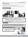
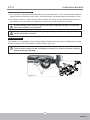
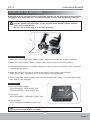
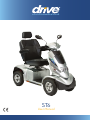
www.drivemedical.co.uk
ST6
User Manual
ST-6
Instruction Booklet
TABLE OF CONTENTS
INTRODUCTION --------------------------------------------------------1
IMPORTANT PRECAUTIONS ----------------------------------------2
ELECTROMAGNETIC INTERFERENCE AND WARNINGS ----3
IDENTIFICATION OF PARTS ----------------------------------------5
CHARGING THE BATTERIES --------------------------------------11
DISASSEMBLING YOUR SCOOTER ------------------------------13
LCD DISPLAY PANEL ------------------------------------------------15
CAUTION ---------------------------------------------------------------22
TECHNICAL SPECIFICATIONS ------------------------------------23
INSPECTION CHECKS ----------------------------------------------24
ISSUE 1
ST-6
Instruction Booklet
INTRODUCTION
Thank you and congratulation on purchasing your new Drive Medical Ltd. Mobility
Scooter. It is designed to provide you with transportation ability indoors and outdoors.
We pride ourselves on providing safe and comfortable products. Our goal is to ensure
your complete satisfaction. We sincerely hope you enjoy your new Mobility Scooter.
Please read and observe all warning and instruction provided in owner's manual before
you operate with various convenient function of this scooter. Also, please retain this booklet
for future reference.
If you have any question, you can contact :
or your local dealer:
Information of European Representative :
EMERGO EUROPE
Molenstraat 15
2513 BH, The Hague
The Netherlands
1
ISSUE 1
ST-6
Instruction Booklet
IMPORTANT PRECAUTIONS
•This scooter is designed for single person use only at any one time.
•Maximum User Weight is 226 kg / 498 Ibs
•Turn key off before getting on or off.
•Always drive carefully and be aware of others using the same area.
•Always use pedestrian crossings wherever possible. Take extreme care when crossing
roads.
•Do not drive on slope exceeding 9 degree, and take extreme care when turning on slope.
•Do not use full power when turning to sharp corner.
•Take great care and drive in low speed when backing up, riding downhill or on uneven
surface, and climbing curb.
•Please use the lowest speed when driving through the descending road or uneven terrain.
If speed is too fast, leave your hand off the handle bar, let the scooter stop. Make sure
safety and start again.
•The weight capacity limit at different ramp degree (please refer to following picture).
85 kg / 9 degree
190 kg / 6 degree
226 kg / 3 degree
•The grade climbing degree will be affected by weight capacity, driving speed, and ramp degree, and scooter parameter.
•To prevent any danger from motor defected; please avoid to drive on long ramp or any uneven terrain.
•A slow speed must always be used when ascending, descending or traversing aslope
or incline and also on uneven terrain, ramps and soft or loose surfaces, such as gravel
or grass.
•To prevent any danger, do not turn around at high speed on ascending, descending ramp.
•Scooter may not operate well in high humidity.
•Do not leave the powered scooter in a rain storm of any kind.
•Do not use the powered scooter in a shower.
•Direct exposure to rain or dampness will cause the scooter to malfunction electrically
and mechanically; may cause the powered scooter to prematurely rust.
•Never put scooter in neutral when staying on slopes.
•Follow traffic laws when riding outside.
•When scooter on moving transport vehicles, do not sit or stay on scooter.
2
ISSUE 1
ST-6
Instruction Booklet
ELECTROMAGNETIC INTERFERENCE
AND WARNINGS
CAUTION: It is very important that you read this information regarding the possible
effects of Electromagnetic Interference on your motorized scooter.
Powered wheelchairs and motorized scooters may be susceptible to electromagnetic
interference (EMI), which is interfering electromagnetic energy (EM) emitted from sources
such a radio stations, TV stations, amateur radio (HAM) transmitters, two-way radios, and
cellular phones. The interference (from radio wave sources) can cause the motorized
scooter to release its brakes, move by itself, or move in unintended directions. It can also
permanently damage the motorized scooter control system. The intensity of the interfering
EM energy can be measured in volts per meter (V/m). Each motorized scooter can resist
EMI up to a certain intensity. This is called its "immunity level." The higher the immunity
level, the greater the protection. At this time, current technology is capable of achieving
at least a 20 V/m immunity level, which would provide useful protection from the more
common sources of radiated EMI. The immunity level of this motorized scooter model is
not known.
There are a number of sources of relatively intense electromagnetic fields in the everyday
environment. Some of these sources are obvious and easy to avoid. Others are not
apparent and exposure is unavoidable. However, we believe that by following the warnings
listed below, your risk to EMI will be minimized.
The sources of radiated EMI can be broadly classified into three types :
1.Hand-held portable transceivers (transmitters-receivers) with the antenna mounted
directly on the transmitting unit. Examples include: citizens band (CB) radios, "walkie
talkie," security, fire, and police transceivers, cellular telephones, and other personal
communication devices
Some cellular telephones and similar devices transmit signals while
they are ON, even when not being used
2.Medium-range mobile transceivers, such as those used in police cars, fire trucks,
ambulances, and taxis. These usually have the antenna mounted on the outside of the
vehicle; and
3.Long-range transmitters and transceivers such as commercial broadcast transmitters
(radio and TV broadcast antenna towers) and amateur (HAM) radios
Other types of hand-held devices, such as cordless phones, laptop
computers, AM/FM radios, TV sets, CD players, and cassette players,
and small appliances, such as electric shavers and hair dryers, so far as.
we know, are not likely to cause EMI problems to your motorized scooter.
3
ISSUE 1
ST-6
Instruction Booklet
Motorized Scooter Electromagnetic Interference:
Because EM energy rapidly becomes more intense as one moves closer to the transmitting
antenna (source), the EM fields from hand-held radio wave sources (transceivers) are of
special concern. It is possible to unintentionally bring high levels of EM energy very close
to the motorized scooter control system while using these devices. This can affect
motorized scooter movement and braking. Therefore, the warnings listed below are
recommended to prevent possible interference with the control system of the motorized
scooter.
Warnings:
Electromagnetic interference (EMI) from sources such as radio and TV stations, amateur
radio (HAM) transmitters, two-way radios, and cellular phones can affect motorized scooters.
Following the warnings listed below should reduce the chance of unintended brake release
or motorized scooter movement which could result in serious injury.
1.Do not operate hand-held transceivers (transmitters-receivers), such as citizens band
(CB) radios, or turn ON personal communication devices, such as cellular phones, while
the motorized scooter is turned ON;
2.Be aware of nearby transmitters, such as radio or TV stations, and try to avoid coming
close to them;
3.If unintended movement or brake release occurs, turn the motorized scooter OFF as
soon as it is safe;
4.Be aware that adding accessories or components, or modifying the motorized scooter,
may make it more susceptible to EMI; and
There is no easy way to evaluate their effect on the overall immunity of
the motorized scooter.
5.Report all incidents of unintended movement or brake release to the distributor listed
on the inside front cover of this manual. Note whether there is a source of EMI nearby.
Important Information:
1.20 volts per meter (V/m) is a generally achievable and useful immunity level against
EMI (as of May 1994). The higher the level, the greater the protection.
2.The immunity level of this product is at least 20/Vm.
4
ISSUE 1
ST-6
Instruction Booklet
IDENTIFICATION OF PARTS
Before you take your first trip, you should familiarize yourself well with the operation of
the scooter and with all operating elements. Take your time to test all functions and driving
modes.
Wigwag
22" Captain Seat
Hand Brake
Tiller Angle
Adjustment
Angle Armrest
Adjustment
Seat fore-aft
Adj Lever
Seat Back Angle
Adjustment
Headlight
Tiller Storage
Compartment
Turn Signal
Rear Bumper
Front Bumper
Swivel Lever
Side Reflector
Figure 1 - ST-6 Front View
Left Turn
Indicator
Headlight
Indicator
Power
Indicator
High Speed
Indicator
Right Turn
Indicator
Hazard
Light
Rear Mirror
Acceleration
Rear Bag
N-D Lever
Turn Signal
Horn
Left Turn
Signal
Headlight
Right Turn
Signal
Rear
Reflector
Deceleration
Hi/Lo Switch
Anti-Tipper
Figure 3 - ST-6 Rear View
Figure 2 - ST-6 Control Panel
5
ISSUE 1
ST-6
Instruction Booklet
FUNCTION OF PARTS:
Main Key Switch (A)
1.Turn the key to the right - Turn the scooter on
2.Turn the key to the left - Turn the scooter off
Always ensure that the scooter is switched
off before getting on or off the scooter and
before removing any items of the scooter
(A)
Turning the scooter OFF whilst driving will
bring the scooter to an abrupt stop and
danger.
Figure 4
TOP CONTROL PANEL
Hazard Light (B) : Switch on by pressing once, switch
off by pressing again. Press hazard light button once,
the right/left lights and parking indicator start to flash,
warning tone acts as well; If the Hazard lights are activated,
with the key switched to the on position, the lights will
continue to flash even when the key is switched off. The
(I)
(J)
(D)
(E) (F) (G)
Hazard light button should be depressed to cancel the
flashing.
(H)
(B)
Figure 5
Horn (D) : Press horn button once to sound warning tone when necessary.
Left Turn Signal (E) : Press Left Turn Signal button once, the front and rear left turn
indicators start to flash, and warning tone sounds simultaneously;
press button again to switch off the turn indicators/signal and tone.
Right Turn Signal (G) : Press Right Turn Signal button once, the front and rear right
turn indicators start to flash, and warning tone sounds simultaneously;
press button again to switch off the turn indicators/signal and tone
Headlight (F) : Press headlight button once to switch on, switch off by pressing again.
Acceleration (H) : Press acceleration button once to increase speed, fine tune in 1'5
speeds.
Deceleration (J) : Press acceleration button once to decrease speed, fine tune in 1'5
speeds.
Hi/Lo Switch (I) : Press H/L Speed button once, the High/Low Speed Indicator will
light on, means driving in high speed mode; Press again, the indicator
will extinguish means driving in low speed mode.
(Hi/Lo speed will vary depend on your current speed settings)
6
ISSUE 1
ST-6
Instruction Booklet
Tiller Storage Compartment (K) Provide you a spacious room to put things.
Hand Brake (L). Hold brake (L), when immediate stop is required.
If you have to brake in an emergency, simply release the thumb lever and
hold hand brake, which will bring you to a halt!
(K)
(L)
Figure 6
Wigwag Lever Operation
Pull the right-hand drive lever (N) carefully to travel forwards.
Pull the left-hand drive lever (M) carefully to travel in reverse.
(This can be reversed if required by local dealer.) Releasing both, engages automatic
brake. These are also your accelerator. The further you depress them, the faster you
go. (Subject to the position of the Rabbit / Turtle control).
Keep LCD display panel and Wigwag Lever dry, if panel and Wigwag Lever
get wet, allow to dry out before using.
(O)
(N)
(M)
Figure 8
Figure 7
Steering Adjustment
By pressing angle adjustment (N) down to adjust to any comfortable angles.
Adjust angle adjustment while driving is prohibited.
Adjust steering to the foremost position before and after getting on the scooter.
7
ISSUE 1
ST-6
Instruction Booklet
Seat Fore-Aft Adjustment (P)
Pull the Seat fore-aft Adj Lever (Q) to disengage the seat (P). Slide the seat forwards or
backwards into the required position. Let go of the lever (Q) again to lock the seat into
its required position.
When driving the scooter, set the seat (P) at foremost position to prevent
tip over.
Sit firmly on seat after getting on the scooter, do not stand on the foot rest
to prevent tipping over or damaging to the scooter.
Angle Armrest Adjustment (R)
Pull the lever (S) and adjust the armrest to the required angle.
Pull the armrest up when get on or off the scooter.
Do not hang heavy parts on the armrests to cause tip over.
(S)
(R)
(P)
Figure 9
(Q)
Figure 10
Seat Swivel Adjustment
Pull the lever (T) upwards to disengage and rotate seat (P) to required angle, Let go of
the lever (T) to lock the seat into its required position.
Seat Back Angle Adjustment
Pull the lever (U) upwards to adjust backrest's angle, then release the lever when adjusted
to required position.
(P)
(T)
Figure 11
(U)
Figure 12
For safety reasons the backrest's position must remain vertical before driving.
8
ISSUE 1
ST-6
Instruction Booklet
Seat (P) Height Adjustment
1.Refer to page 13 for disassembly, then remove seat (P) and rear shroud (Z). (Figs 18 & 19)
2.Remove screw, nut and washer from seat post (V). (Fig 13)
3.Adjust seat post (V) to desired height, and attached tightly with screw, nut and washers. (Fig 13)
4.Then assemble the rear shroud (Z), seat (P) back to its original position. (Fig 18 & 19)
Seat (P) Electrical Lifter (Optional)
1.Press seat lifter button
(W) lightly, seat will raise.
press
lightly, seat will lower.
(V)
(W)
(P)
Figure 13
Figure 14
•Do not operate this function on a slope, or in motion or under unstable
condition.
•The main purpose of this function is to assist you to reach certain height.
•Seat's position must remain at the lowest before driving.
•Do not set N-D lever at N, before setting the seat at lowest position.
•Please keep the center of gravity of the scooter in the middle, to prevent
the scooter tipping over.
N-D Lever Adjustment :
1.When scooter stopped or malfunction, press the unlocking knob on the N-D lever (X).
Push the N-D lever forwards this will allow you to push the scooter by hand.
Freewheel operation is only recommended on flat surfaces, never on
gradients. Never leave your scooter on a gradient with its motors disengaged.
Always re-engage the motors immediately after pushing the scooter.
The scooter won't operate, if the
scooter is setting at N position,
to restore to it's normal status,
you must switch the power off
and adjust to D position, then
switch the power on.
D
N
(X)
Figure 15
9
ISSUE 1
ST-6
Instruction Booklet
Proportional Speed Reduction :
1.The scooter is equipped with proportional speed reduction. It will automatically reduce
speed when encountering a corner, reducing speed corresponding to the angle of turn.
2.For safety reasons, when pushing the scooter by hand, if a pre-determined speed is
exceeded, the controller automatically switches on and brakes the scooter.
Avoid shifting your center of gravity as well as abrupt changes of direction
when the scooter is in motion.
Reduce speed before negotiating corners! Only accelerate when you have
come out of the corner!
Tie - Down Hook :
To enable you to transport your scooter safely and securely there are 2 additional tie down
hooks located on the underside of the scooter. (Fig 16)
When fixed on a transportation system, N-D lever (X) must located at D position.
This scooter must not be occupied or used as a seat in a motor vehicle
whilst being transported.
Figure 16
(Y)
10
ISSUE 1
ST-6
Instruction Booklet
CHARGING THE BATTERIES
Batteries must be charged before using the scooter for the first time and should be
recharged after each day use. You will need the scooter and the battery charger.
Each country may supply different charger. The charging procedure
may be different from below. If you require more details, please contact
your authorized dealer.
Be sure the scooter key is in the OFF position
Figure 17
Operating Instruction
1.Make sure the power cord, battery cable, battery terminals are in good condition.
2.Make sure the charge output voltage is the same as the connecting battery.
3.Connect the connector of battery charger to the connector of battery firstly, and then
connect the AC power.
4.Make sure the AC voltage is correct and plug in the power cord normally.
The LED (Power) light will turn on when electric current passes.
5.During charging, LED (Charge) will indicate orange light. When it turns to green light,
that means fully charged.
LED Indication
◎Connect Power supply:
LED (POWER) - RED LIGHT ON
LED (CHARGE) - RED LIGHT ON
◎CC mode:
LED (CHARGE) - ORANGE LIGHT ON
◎Full charged:
LED (CHARGE)-GREEN LIGHT ON
Maintenance & Repair must only be carried out by a Competent Engineer
or Authorised Dealer or Agent.
11
ISSUE 1
ST-6
Instruction Booklet
The time needed to recharge will vary depending on the depletion of the
batteries. (Approx. 8 hours). Do no continuous charging for over 15 hours.
Troubles Shooting
1.LED(POWER) light is off
Make sure the battery charger output connector is connected properly, and make sure
the battery voltage is higher than the lowest charge voltage range
2.LED(CHARGE)light is off
Check if the connectors are correctly connected.
3.During Charging, LED(CHARGE) light is flashing red, then into the charging abnormal
protected.Need to unplug the AC power, to wait for the power indicator light turns off
completely, then plug in the AC power supply, return to normal work
Warnings
•Fully charge batteries at least once a month, or more if you use scooter regularly.
Charge after each trip exceeding 3 kilometers.
•If storing your scooter for some time (1 month or more), make sure that batteries are
fully charged, and on returning, charge them again before using scooter.
•Batteries will only give maximum performance after scooter has been used, and
batteries have been recharged up to 10 times. A bit like breaking in a new car.
12
ISSUE 1
ST-6
Instruction Booklet
DISASSEMBLING YOUR SCOOTER
Seat (P) disassembling :
Pull the lever (T) upwards to disengage the seat (P), hold the seat (P) firmly by the
backrest and front edge and remove it upwards.
If found the seat (P) uneasy to remove, hold seat swivel lever (R), and then
rotate the seat to reduce resistance then pull up.
Proceed with caution, if you need assistance, please have some one to help you
Rear Shroud (Z) and Batteries (C1) Disassembling :
1.Remove rear shroud (Z) upwards. (Figure 18)
2.Unplug one battery connector (A1) (Figure 19)
3.Release Velcro (B1) (Figure 20)
4.Remove two batteries (C1) (Figure 21)
Take into account the heavy weight of the batteries (C1) please consider
your physical condition before disassembling.
DO NOT short-circuit battery terminals (C1).
Battery's red wire plug connects to red positive location, black wire plug
connects to black negative location.
For safety reason, please wash your hands after disassembly.
(A1)
(P)
(Z)
(T)
Figure 18
Figure 19
(B1)
(C1)
(C1)
Figure 20
Figure 21
13
ISSUE 1
ST-6
Instruction Booklet
Resetting the Circuit Breaker :
Resetting the circuit breaker may be needed if scooter does not turn on and when a scooter's
circuit over loaded, the circuit breaker will trip.
1.To reset, press the circuit breaker button (D1) upwards.
2.Reassemble the rear shroud (Z).
3.Reassemble the seat.
If the circuit breaker trips repeatedly, IMMEDIATELY unplug charger and contact dealer
or a qualified technician.
NEVER defeat or bypass the circuit breaker.
ONLY replace with a circuit breaker of the same rating.
(D1)
Figure 22
Figure 23
14
ISSUE 1
ST-6
Instruction Booklet
LCD DISPLAY PANEL
Figure 25
Function Buttons & Indicators
ITEM
SPECIFICATION
Control Buttons
Hazard Light, Horn, Right Turn Light, Headlight, Left Turn
Light, Turtle(decelerate), H/L Speed, Rabbit(accelerate)
LED Indicators
Status Indicator (Green)
Headlight Indicator (Green)
Left / Right Indicators (Green)
High/Low Speed Indicator (Green)
Connector
20PIN
LCD Back Light
Blue LEDs illuminate while key on.
Function Descriptions
FUNCTION
SPECIFICATION
1.Full Lighting
Control
Headlight , Taillight, Left/Right Turn Signal, Hazard
Light, Brake Light
2.Speedometer
7 Segment display (2 1/2 digits +1 decimal)
"km/h" and "mph" symbol
3.Digital High / Low
Speed Control
Low (L) Speed: 1 - 5 Rate
High (H) Speed: 1 - 5 Rate
4.Power Indicator
Battery discharge and charging indicator (6 segments)
5.Malfunction
Messages
Error code: 1~7 (1 digit) + LED Indicator
6.Key On Display
LCD full segments display
7.Warning Tone
Setup
Volume adjustment for tones of Left/Right turn light,
Parking light, Low voltage warning and horn
15
ISSUE 1
ST-6
Instruction Booklet
1.Full Lighting Control
Headlight, Taillight
ITEM
Operation
Feature
Control Mode
SPECIFICATION
Take exterior headlight switch as determinant signal.
Press button to turn on headlight & turn signal and
headlight indicator.
Press button again to turn off headlight & turn signal and
headlight indicator.
Usage Condition
While (1) controller shut down (2) on power-saving mode,
all functions closed.
Remarks
(1) Loop Load of Headlight : 12V/50W Max
(2) Loop Load of Taillight : 24V/50W Max
(3) With "short circuit" and "overload" protection
Brake Light
ITEM
Operation
Feature
Control Mode
SPECIFICATION
Take accelerator & manual brake as determinant signal.
While
(1)accelerator is moved from Forward to Center position,
(2)accelerator is moved from Backward to Center position or
(3)manual brake is operated, the vehicle is considered to brake.
The brake light will be lit After 5 seconds, the light
will switch off automatically.
Usage Condition
While (1) controller shut down (2) on power-saving mode,
all functions closed.
Remarks
(1) Loop Load of Brake light: 24V/50W Max
(2) With "short circuit" and "overload" protection
Turn Light and Parking Lights
ITEM
DESCRIPTIONS
(Control Mode)
Left Turn Light
Press left-indicator button once, the left light and left
indicator starts to flash, and warning tone sounds
simultaneously; press button again to switch off the
indicator/light and tone.
Right Turn Light
Press right-indicator button once, the right light and right
indicator starts to flash, and warning tone sounds
simultaneously; press button again to switch off the
indicator/light and tone.
16
ISSUE 1
ST-6
Instruction Booklet
Automatic Turn Off
The direction lights and indicators will be turned off
automatically while flashing for 30 seconds.
Hazard Lights
Press hazard indicator button once, the right/left lights
and hazard indicator start to flash, warning tone acts as
well; press button again will turn off above indicators and
tone. To activate the parking lights while KEY ON, the
lights would keep flashing even KEY OFF.
Determinant
Condition
There is no priority between left / right lights or parking
lights.
Usage Condition
While (1) controller shut down (2) in charging-mode,
the function will be disabled.
Flicker Frequency
1 second, Duty 50%
Warning Tone
Frequency
1 second, Duty 30%
Remarks
(1)Load circuit for left turn light: 24V/50W max
(2)Load circuit for right turn light: 24V/50W max
(3)With "short circuit" and "overload" protection
(4)The volume of warning tones for left/right turn lights,
parking lights could be adjusted.
2.Speedometer
ITEM
Operation
Feature
DESCRIPTIONS
Use optical coupler to detect the signal and transfer to
related speed.
Speed displays 60km/h while it's on 1400 rpm.
Display Errors
+15~20%
Display Range
0.0 ~ 30.0, display resolution: 0.5
Operational
mode of
speedometer
Speedometer Mode
H
F
km/h
E
When "km/h" is displayed, speed will be indicated in km
per hour.
When "MPH" is displayed, speed will be indicated in miles
per hour.
When "/h" is displayed, the function of speedometer will
be disable.
17
ISSUE 1
ST-6
Instruction Booklet
(This display will be applied to the model that is not equipped
with optical coupler) And the display will be replaced to
WIP(accelerator) operation indicator as follows:
Standby Indication
H
F
/h
E
Forward Indication
H
F
/h
E
Backward Indication
H
F
/h
E
Setup Mode
(Unit change)
Press
+
together for 3 secs to enter setup mode.
While「km/h」/ (「MPH」) is flashing, press
or
to
switch to「MPH」/(「km/h」).
Setup Mode
(Unit change)
The user could quit the setup mode with the following
conditions.
(1)Leave
or
buttons alone for 15secs.
(2)Press any button of Parking light, Horn, Turn light or
Headlight, the definitive settings will be stored and
return to normal speedometer mode.
18
ISSUE 1
ST-6
Instruction Booklet
3.Digital High / Low Speed Control
ITEM
Operation
Feature
Control Mode
DESCRIPTIONS
Press「H/L Speed」 button to switch High/Low speed
Press
or
to fine tune in 5 speeds
Press「H/L Speed」 button once, the High/Low Speed
Indicator ( ) will light on. Press again, the indicator will
light off.
Press
button to increase the speed
Press
button to decrease the speed
H
H
%
(Max)
Speed Display
Usage Condition
L
%
(Max)
20
10
40
20
60
30
80
40
100
50
While (1) controller shut down (2) in charging-mode, the
function will be disabled.
4.Power Indicator
ITEM
Discharge
Capacity
DESCRIPTIONS
Capacity (%)
40%
55%
Status Display
70%
85%
100%
F
F
F
F
F
E
E
E
E
E
30%
F
E
Flashing
(Status indicator LED will be flashing)
Operation
Characters
The segments will decrease only, won't increase.
19
ISSUE 1
ST-6
Instruction Booklet
Low Voltage
Warning Tone
When the battery capacity is lower than 30%, the warning
tone will be beeped once with "BiBi - BiBi -- BiBi"
3 short double beeps.
Flicker Frequency
Once per two seconds
Usage Condition
While (1) controller shut down (2) in charging-mode,
the function will be disabled.
Charge Status
ITEM
Charge Status
DESCRIPTIONS
The charging status displays with segments cycling,
increasing only, won't decrease.
H
F
km/h
E
Charging
Indicating
Capacity(%)
Display status of segments
40%
55%
70%
80%
90%
F
F
F
F
F
F
E
E
E
E
E
E
100%
F
E
displays with 6 segments
Increasing ratio
0.5 second
Operation
Feature
(1) The segments will increase only, won¡¦t decrease.
(2) Take PIN3 (CH3) of charger as determinant signal. No
matter of KEY ON or KEY OFF, the charging mode will
be activated once CH3 is connected to Ground(L)
(3) The LCD back light will be ON while any button is pressed.
It will light off automatically in 5 seconds if no button
has been pressed.
Remarks
Displayed segments are for reference only. Please refer to
indicator of charger for more accurate charging status.
20
ISSUE 1
ST-6
Instruction Booklet
5.Malfunction Messages
ITEM
DESCRIPTIONS
Operation
Feature
Take the connector pin (KEY) of controller as determinant
signal, then converts it into digital codes.
Usage
Condition
When the controller sends out an error message,
(LED)
starts flashing to wait for confirming and display the "Error
message code" as follows.
flashing
LCD
code
Status
1
Battery needs charging soon.
2
Low voltage, needs charging now
3
Over voltage
4
Over current
5
Park Brake is lost or faulted
6
Accelerator not aligns in center
7
Accelerator is broken or faulted
8
Motor is broken or faulted
9
Others
6.Key On Display
ITEM
Initial Status
DESCRIPTIONS
When scooter power on, the backlight and all LCD segments
will be tuned on for 3 seconds, then switch to the default
working mode automatically.
7.Warning Tone Setup
ITEM
Operation
Feature
DESCRIPTIONS
The volume of warning tones of Parking light, Reverse, Horn,
Low voltage and Turn signal could be adjusted or turned off.
(except you cannot turn off the Horn)
Function
Buttons
(A+B)
Status
Initial
Parking
LightWarning
Tone
Less Loud
Reverse
Warning
Tone
Less Loud
Volume
of Horn
Loud
Low Voltage
Warning
Tone
Less Loud
Turn Light
Warning
Tone
Less Loud
Volume
>> Increase volume
<< Decrease volume
Volume
Loud
Less Loud
Normal
Quiet
Silent
21
ISSUE 1
ST-6
Instruction Booklet
CAUTION
1.Obstacle Climbing :
Your scooter can climb obstacles and kerbs of up to 6cm in height. Never attempt to
overcome an obstacle when on an uphill or downhill gradient! Always approach obstacles
straight on! Ensure that the front wheels and rear wheels move over the obstacle in one
stroke, do not stop halfway!
2.The maximum gap the scooter can drive over is 22cm,
•When driving scooter on ramp, adjust body center of gravity to keep scooter more safety.
General driving posture
On ramp, forward your body will
let scooter more safety.
In unlikely event of a panel display error, you need to re-set the display
system by cycling the on/off main switch. The display circuitry is independent
of the motor control system. A display console error does not affect scooter
speed control.
OTHER
1.Charge the batteries after each trip, if the scooter is not used for some time batteries
must be charged at less once a month. make sure that batteries are fully charged, and
on returning, charge them again before using scooter.
2.Check the battery gauge before driving to prevent power depletion.
3.Do not disassemble battery and open sealed parts by yourself to prevent electric shock
and burns from acid leakage.
4.Adjust speed to a slow speed when starting off to prevent sudden acceleration.
5.Never attempt to drive downhill backwards.
6.Try not to drive scooter at night or in rain or bad weather.
7.If storing your scooter for a long time (1 month or more), make sure that battery are
fully charged, then disconnect the two batteries plugs (W), and the store scooter in a
dry location.
22
ISSUE 1
ST-6
Instruction Booklet
TECHNICAL SPECIFICATIONS
Overall Length
1600 mm / 63"
Overall Width
720 mm / 28.4"
Overall Height
1280 mm / 50"
Wheels : Front
380 mm / 15"
Wheels : Rear
380 mm / 15"
135.2 kg / 298 lbs
Weight w/ Batteries
12.8 kmph / 8 mph
Max. Speed
Maximum
Weight Capacity
150 kg / 331 lbs
Ground Clearance
110 mm / 4.3"
Maximum Safe Slope
9 degree
Kerb Climbing
60 mm / 2.4"
Turning Radius
1860 mm / 73.2"
Suspension
Brake
Front & Rear
Manual hand Break & Electro-Mechanical
Seat Type
Sliding and Swivel Reclining
Captain W/Headrest
Seat Width
559 mm / 22"
Motor Size
700W, 3650 r.p.m
(2) 12V. 75Ah
Battery
(x2) 50 kg / 110 lbs
Weight Of Batteries
Weight of Heaviest
Component
85.5 kg / 188.5 lbs
50 km / 28 Miles
Travel Range
Battery Charger
Electronics
15A Off Board
On / Off Key Switch, Battery Level
Indicator, Speed Control Knob
*Subject to change without notice.
23
ISSUE 1
ST-6
Instruction Booklet
INSPECTION CHECKS
Seat and backrest padding:
Monthly
Weekly
Maintenance Jobs
When
Delivered
The following table lists inspection checks that should be performed by the user and their
intervals. If the mobility device fails to pass one of the inspection checks, please contact
your authorised Drive Medical dealer.
X
- Check for perfect condition.
Tyres:
- Have tyres checked for specified air pressure (2,5 bar).
X
X
Front wheels:
- Front wheels must spin smoothly.
X
- If wheels wobble or do not spin easily, adjust steering pivot pin
or front wheel bearing.
X
Rear wheels:
- Test wheel for firm seat on the axle drive shaft.
X
- Rear wheels must spin without wobbling
X
Electronics / Electrical System:
- Check all plug connections for condition and firm connection.
- Have batteries been fully charged before the daily operation?
- Are all holders, screws firmly fixed, tight and safe?
- Are all electric bulbs of the lighting system (if applicable) in
working order?
X
Before every trip
X
Before each trip
Cleaning:
When necessary
- Clean all parts carefully.
24
ISSUE 1
CERTIFICATE OF NEWNESS
THIS DOCUMENT SHOULD BE SUBMITTED WITH THE V55/4 FORM
TO REGISTER THE VEHICLE WITH THE DVLA.
Make
Drive Medical
Type of Body
Metal and Plastic
Serial Number
Weight w/Batteries
135.2kg / 298lb
Top Speed
12.8 kmph / 8 mph
I declare that the mobility scooter described above is new and
unused, and has not been registered before.
Signed:
Mark Harris
On behalf of Drive Medical Ltd
Date:
Drive Medical Ltd,
Ainley’s Industrial Estate, Elland,
West Yorkshire HX5 9JP
Warranty Information
Drive Medical ST6 Scooters are warranted for 12months (24 months frame) from the
date of purchase on side frames and crossbars. (NB Batteries are warranted for 12 months.)
»
»
»
»
»
During the warranty period any parts that have become defective due to
faulty workmanship or material will be repaired or replaced without charge
by Drive Medical supplier/dealer
The warranty excludes tyres, punctures and items that become worn due to
normal wear and tear such as upholstery and armrest pads
The warranty excludes all items that have been subject to undue
wear and tear and misuse
Unauthorised changes or modifications will forfeit your warranty
If a defect or fault is discovered, the Drive Medical supplier/dealer
from whom the Wheelchair was purchased should be notified immediately
Limitation of Liability
The warranty does not extend to the consequential costs resulting from fault clearance, in
particular freight and travel costs, loss of earnings, expenses, etc. The manufacturer will not
accept responsibility for any damage or injury caused by misuse or non-observance of the
instructions set out in this user manual.
Dealer Stamp
Drive Medical Ltd
North Road,
Bridgend Industrial Estate
Bridgend, CF31 3TP
Tel: +44 (0) 1656 664700
Fax: +44 (0) 1656 664727
Email: [email protected]
www.drivemedical.co.uk