1
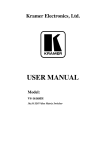
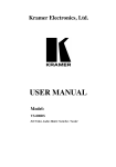
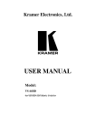
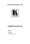
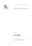
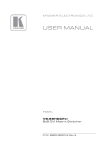
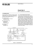
Kramer Electronics, Ltd.
USER MANUAL
Models:
VS-402xl, 4x2 Vertical Interval Video-Audio Matrix Switcher
VS-602xl, 6x2 Vertical Interval Video-Audio Matrix Switcher
Contents
Contents
1
2
3
4
5
5.1
5.2
5.3
Introduction
Getting Started
Overview
Your Vertical Interval Video-Audio Matrix Switcher
Connecting a Vertical Interval Video-Audio Matrix Switcher
Controlling via RS-232 (for example, using a PC)
Controlling via RS-485
Setting the Dipswitches
1
1
2
2
5
6
6
7
5.3.1
Setting the MACHINE #
5.4
6
6.1
6.2
6.3
Connecting the REMOTE Connector
Cascading Vertical Interval Video-Audio Matrix Switchers
Cascading Units in an Input Expansion Configuration
Cascading a set of Units in a (RGB) Parallel Configuration
Cascading Individual Units in a Control Configuration
9
10
10
12
14
6.3.1
6.3.2
Control Configuration via RS-232 and RS-485
Control Configuration via RS-485
14
15
6.4
7
7.1
Looping Units in an Increased Output Configuration
Operating the Vertical Interval Video-Audio Matrix Switcher
Choosing the Audio-Follow-Video or Breakaway Option
16
17
18
7.1.1
7.1.2
Setting the Audio-Follow-Video Option
Setting the Breakaway Option
18
18
8
9
10
Technical Specifications
Table of Hex Codes for Serial Communication
Communication Protocol
18
19
20
8
Figures
Figure 1: Vertical Interval Video-Audio Matrix Switchers
Figure 2: VS-602xl Underside
Figure 3: Connecting a PC without using a Null-modem Adapter
Figure 4: Controlling via RS-485 (for example, using a VS-3000)
Figure 5: SETUP Set of 8 Dipswitches
Figure 6: Remote Connector PIN # Settings
Figure 7: Cascading Units in an Input Expansion Configuration
Figure 8: Cascading a set of 3 Units in a (RGB) Parallel Configuration
Figure 9: Cascading Individual Units in a Control Configuration via RS-232 and RS-485
Figure 10: Cascading Individual Units in a Control Configuration via RS-485
Figure 11: Adding Outputs by Looping Units
3
5
6
7
8
9
12
13
15
16
17
i
Contents
Tables
Table 1: Front Panel Vertical Interval Video-Audio Matrix Switcher Features
Table 2: Rear Panel Vertical Interval Video-Audio Matrix Switcher Features
Table 3: VS-602xl Underside Features
Table 4: Dipswitch Settings
Table 5: Machine # Dipswitch Settings
Table 6: Technical Specifications of the Vertical Interval Video-Audio Matrix Switcher
Table 7: VS-402xl/VS-602xl Hex Codes for Switching via RS-232/RS-485
Table 8: Protocol Definitions
Table 9: Instruction Codes
ii
4
4
5
8
9
19
19
20
21
KRAMER ELECTRONICS, LTD.
Introduction
1
Introduction
Dedication by Kramer Electronics since 1981, to the development and
manufacture of high quality video/audio equipment, makes the Kramer line
an integral part of the finest production and presentation facilities in the
world. In recent years, Kramer has redesigned and upgraded most of the line,
making the best even better! The Kramer line of professional video/audio
electronics is one of the most versatile and complete available, and is a true
leader in terms of quality, workmanship, price/performance ratio and
innovation. In addition to our high quality Kramer switchers and matrices, we
also offer excellent distribution amplifiers, remote controllers, processors,
interfaces, scalers and computer-related products.
Congratulations on purchasing your Kramer VS-402xl 4x2 Vertical Interval
Video-Audio Matrix Switcher and/or VS-602xl 6x2 Vertical Interval
Video-Audio Matrix Switcher.
Your Kramer VS-402xl/VS-602xl is ideal for the following typical
applications:
Live broadcast or presentation applications such as switching between
cameras in real-time
CCTV, home theater
Rental and staging applications
Video production studios
The VS-402xl and/or the VS-602xl package includes the following items:
Vertical Interval Video-Audio Matrix Switcher
Power cord
Windows 95/98/NT TM Kramer control software
Null-modem adapter
This user manual
2
Getting Started
We recommend that you:
Unpack the equipment carefully and save the original box and packaging
materials for possible future shipment
Review the contents of this user manual
1
Overview
3
Overview
The Kramer VS-602xl (a 6x2 switcher) and VS-402xl (a 4x2 switcher) are
high performance vertical interval matrix switchers for composite video and
stereo balanced audio signals. Both are true matrix switchers - enabling the
user to route any input to any or all outputs simultaneously.
In addition, both the VS-602xl and the VS-402xl:
Have video bandwidth that exceeds 300 MHz, ensuring that they remain
transparent even in the most critical applications
Include audio-follow-video or audio breakaway option
Produce glitch-free transitions, when sources share a common reference
sync1
Include 2 sets of INPUT SELECTOR buttons (one set for each output)
and 5 front panel control buttons
Include 2 duplicate outputs per set of INPUT SELECTOR buttons (4
outputs in total)
Include a “Take” button2 for precise switch control and a “Lock” button
to prevent tampering with the front panel
Are controllable via the front panel buttons, or remotely by RS-485 or
RS-232 serial commands transmitted by a touch screen system, PC, or other
serial controller
Achieving the best performance means:
Connecting only good quality connection cables, thus avoiding
interference, deterioration in signal quality due to poor matching, and elevated
noise levels (often associated with low quality cables)
Avoiding interference from neighboring electrical appliances that may
adversely influence signal quality
Positioning your Kramer VS-402xl or VS-602xl in a location free from
moisture and away from excessive sunlight and dust
4
Your Vertical Interval Video-Audio Matrix Switcher
Figure 1 illustrates the front and rear panels of both the VS-402xl and the
VS-602xl. Tables 1 and 2 define their front and rear panels.
1 As it switches during the vertical interval
2 Also enables the user to place multiple switches in a queue and then activate them with one touch of this button, or via a
single serial command
2
KRAMER ELECTRONICS, LTD.
Figure 1: Vertical Interval Video-Audio Matrix Switchers
Your Vertical Interval Video-Audio Matrix Switcher
3
Your Vertical Interval Video-Audio Matrix Switcher
Table 1: Front Panel Vertical Interval Video-Audio Matrix Switcher Features
#
Feature
Function
1
2
Illuminated switch supplying power to the unit
Select the input to switch to OUTPUTS 1A and 1B
4
5
6
7
Power Switch
INPUT SELECTOR TO
1
OUTPUT 1 Buttons
INPUT SELECTOR TO
1
OUTPUT 2 Buttons
2
VIDEO Button
2
AUDIO Button
3
AFV Button
TAKE Button
8
LOCK Button
3
Select the input to switch to OUTPUTS 2A and 2B
When pressed actions relate to video
When pressed actions relate to audio
When pressed audio channels follow the video channels
4
Pressing TAKE toggles the mode between the CONFIRM mode and
the AT ONCE mode (user confirmation per action is unnecessary)
Disengages the front panel switches
Table 2: Rear Panel Vertical Interval Video-Audio Matrix Switcher Features
#
Feature
1
AUDIO INPUTS Terminal
1
Block Connectors
SYNC BNC Connector
Sync Source Selector
(IN=Internal) Button
IN BNC Connectors1
LOOP BNC Connectors1
AUDIO OUTPUTS Terminal
Block Connectors
RS-485 Connector
V/A BUS Connector
2
3
4
5
6
7
8
9 RS-232 Connector
10 OUTPUTS 1A; 1B; 2A; 2B
BNC Connectors
11 SETUP
12 REMOTE Connector
13 Power Connector with Fuse
Function
Connects the audio sources
Connects to the external SYNC source
Pushing in selects internal sync5, releasing selects the external sync6
source
Connects the composite video sources
For looping to increase output availability
Connects the 2 audio acceptors
RS-485 detachable terminal block port
DB9F connector connects to the V/A BUS Connector on the next
unit(s) via a short DB9M flat cable when cascading in an input
expansion configuration
DB 9F connector connects to PC or other Serial Controller
Connects to the output acceptors
Dipswitches for setup
Attach a specific PIN to PIN 9 or PIN 10 to switch an input via a
remote dry contact switch7 (refer to section 5.4)
AC connector enabling power supply to the unit
1 Four on the VS-402xl; six on the VS-602xl
2 Refer to section 7.1.2
3 Refer to section 7.1.1
4 When in Confirm mode, the TAKE button illuminates
5 On the IN 1 connector
6 On the SYNC connector
7 The appropriate front panel INPUT SELECTOR button illuminates
4
KRAMER ELECTRONICS, LTD.
Connecting a Vertical Interval Video-Audio Matrix Switcher
Figure 2 and Table 3 define the 6 TERM switches and the 4 trimmers on the
underside of the VS-602xl unit1. Figure 2 shows to which LOOP connector
each TERM switch relates and the location of the Trimmers for adjusting
OUTPUTS 1 and 2 and for adjusting EQ. 1 and EQ. 2.
Figure 2: VS-602xl Underside
Table 3: VS-602xl Underside Features
5
#
1
Feature
TERM Switch
2
3
LEVEL Trimmers
EQ. Trimmers
Function
Move to the right (ON position) to terminate with 75 , or move to the
left for looping2
Adjusts3 the output signal level for OUTPUTS 1 and 2
Adjusts3 the equalization level (EQ.) for OUTPUTS 1 and 2
Connecting a Vertical Interval Video-Audio Matrix Switcher
To connect the VS-402xl/VS-602xl, connect the following4 to the rear panel:
1.
The composite video sources and acceptors, as well as the appropriate
audio sources and acceptors.
2.
The power cord.
1 The underside of the VS-402xl unit contains only 4 TERM switches
2 The factory default
3 Insert a screwdriver into the small hole and carefully rotate it, trimming the OUTPUT level or EQ level
4 Switch OFF the power on each device before connecting it to your VS-402xl/VS-602xl Switcher. After connecting your
VS-402xl/VS-602xl Switcher, switch on its power and then switch on the power on each device. Switching on the
VS-402xl/VS-602xl Switcher, recalls the last status prior to powering down
5
Connecting a Vertical Interval Video-Audio Matrix Switcher
In addition, you can choose to connect the following options:
A PC (when using the Kramer Control software, for example) or other
RS-232 (refer to section 5.1) or RS-485 controller (refer to section 5.2).
A remote dry contact switch (refer to section 5.4)
5.1 Controlling via RS-232 (for example, using a PC)
To connect a PC to the VS-402xl/VS-602xl unit, using the Null-modem
adapter provided with the machine (recommended):
Connect the RS-232 DB9 rear panel port on the VS-402xl/VS-602xl unit
to the Null-modem adapter and connect the Null-modem adapter with a 9 wire
flat cable to the RS-232 DB9 port on your PC
To connect a PC to the VS-402xl/VS-602xl unit, without using a Null-modem
adapter:
Connect the RS-232 DB9 port on your PC to the RS-232 DB9 rear panel
port on the VS-402xl/VS-602xl unit, as Figure 3 illustrates (depending on
whether the PC has a 9-pin or 25-pin connector)
Figure 3: Connecting a PC without using a Null-modem Adapter
You can connect up to 8 VS-402xl/VS-602xl units to the PC via the
Null-modem adapter and the RS-232 port, and the RS-485 ports, as Figure 9
illustrates.
5.2 Controlling via RS-485
You can control a VS-402xl/VS-602xl unit via an RS-485 controller, for
example, a PC (equipped with an RS-485 interface) or a Master
Programmable Remote Control system such as the Kramer VS-3000.
6
KRAMER ELECTRONICS, LTD.
Connecting a Vertical Interval Video-Audio Matrix Switcher
To connect a VS-3000 to a VS-402xl/VS-602xl unit1 (see Figure 4):
Connect the RS-485 terminal block port on the VS-3000 to the RS-485
port on the VS-402xl/VS-602xl unit, as follows:
Connect the “ A” (+) PIN on the RS-485 rear panel port of the VS-3000 to
the “ A” (+) PIN on the RS-485 rear panel port of the VS-402xl/VS-602xl unit
Connect the “ B” (-) PIN on the RS-485 rear panel port of the VS-3000 to
the “ B” (-) PIN on the RS-485 rear panel port of the VS-402xl/VS-602xl unit
If shielded twisted pair cable is used, the shield may be connected to the
“ G” (Ground) PIN on one of the units (for example, on the VS-3000)
1.
2.
Set the VS-402xl/VS-602xl unit as MACHINE # 1, according to Table 5
3.
Set the SETUP dipswitches on the VS-402xl/VS-602xl unit, as follows:
Set Dip 4 ON, Dip 6 ON and Dip 7 ON
Set Dip 5, and Dip 8 OFF
Figure 4: Controlling via RS-485 (for example, using a VS-3000)
5.3 Setting the Dipswitches
Figure 5 illustrates the factory default SETUP dipswitches:
1 You can control up to 8 VS-402xl/VS-602xl units, as section 6.3.2 describes
7
Connecting a Vertical Interval Video-Audio Matrix Switcher
Figure 5: SETUP Set of 8 Dipswitches
Table 4: Dipswitch Settings
Function
DIPS
Machine #
1, 2, 3 Determines the position of a unit in the sequence (refer to section 5.3.1)
RS-485 Termination 4
Description
Input Expansion
5
Set ON to terminate the RS-485 line on the first and last cascaded units
(refer to section 6.1)
Set ON to enable input expansion mode (refer to section 6.1)
Reply
6
Set ON to enable the Reply option in accordance with Protocol 2000
PC 485
7
Set ON when connecting the PC (or other controller) via the RS-485 port,
set OFF when connecting the PC via the RS-232 port or when not
connecting a PC
5.3.1
Setting the MACHINE #
The MACHINE # determines the position of a VS-402xl/VS-602xl unit or a
set of VS-402xl/VS-602xl units in the sequence1, specifying which
VS-402xl/VS-602xl unit is being controlled when several
VS-402xl/VS-602xl units connect to a PC or serial controller. Set the
MACHINE # on a VS-402xl/VS-602xl unit via DIPS 1, 2 and 3, according to
Table 5.
When using a stand-alone VS-402xl/VS-602xl unit, set the MACHINE # to 1.
When connecting more than one VS-402xl/VS-602xl unit, set the first
machine (the Master) that is closest to the PC, as MACHINE # 12.
1 Set the MACHINE # on the first unit to one, on the second unit to 2, on the third unit to 3
2 Set the dipswitches to ON
8
KRAMER ELECTRONICS, LTD.
Connecting a Vertical Interval Video-Audio Matrix Switcher
Table 5: Machine # Dipswitch Settings
MACHINE # DIPSWITCH
1
1
Master
2
3
OFF OFF OFF
2
ON
3
OFF ON
OFF OFF
OFF
4
ON
OFF
5
OFF OFF ON
6
ON
7
OFF ON
ON
8
ON
ON
ON
OFF ON
ON
5.4 Connecting the REMOTE Connector
Connecting the REMOTE DB15F connector to a dry contact switch enables
you to route an input to an output by remote control. To do so, touch
(momentarily) the PIN corresponding to that input to PIN 91 (for output # 2)
or PIN 10 (for output # 1). For example, to connect input # 1 to output # 1,
touch PIN 1 to PIN 10; to connect input # 2 to output # 1, touch PIN 2 to PIN
10. To connect input # 3 to output # 1, touch PIN 3 to PIN 10. To connect
input # 1 to output # 2, touch PIN 1 to PIN 9. To connect input # 2 to output #
2, touch PIN 2 to PIN 9.
Figure 6: Remote Connector PIN # Settings
1 The appropriate front panel INPUT SELECTOR button illuminates
9
Cascading Vertical Interval Video-Audio Matrix Switchers
6
Cascading Vertical Interval Video-Audio Matrix Switchers
For certain applications, you may need more than just 4 or 6 inputs.
Cascading VS-402xl/VS-602xl units1 enables you to expand the number of
inputs by looping up to 8 individual VS-402xl/VS-602xl units.
You can cascade VS-402xl/VS-602xl units, as follows:
Up to 8 interconnected VS-402xl/VS-602xl units in an input expansion
configuration
A set of VS-402xl/VS-602xl units in a parallel configuration (for
example, 2 VS-402xl/VS-602xl units for Y/C, 3 VS-402xl/VS-602xl units for
RGB or YUV, 4 VS-402xl/VS-602xl units for RGBS)
Up to 8 individual VS-402xl/VS-602xl units in a control configuration
Up to 8 interconnected VS-402xl/VS-602xl units in an output expansion
configuration
6.1 Cascading Units in an Input Expansion Configuration
You can cascade up to 8 interconnected VS-402xl/VS-602xl units to form an
input expansion configuration. For example, to create a 48 x 2 switcher, with
48 inputs and 2 outputs, connect as Figure 7 illustrates.
To cascade VS-402xl/VS-602xl units to expand the number of inputs, connect
as follows:
1.
Connect the composite video sources and acceptors, as well as the
appropriate audio sources and acceptors, as section 5 describes.
2.
Connect the RS-232 port on the first VS-402xl/VS-602xl unit (MACHINE
# 1) to the PC using the Null-modem adapter provided with the machine
(recommended), as section 5.1 describes.
3.
Connect the RS-485 terminal block port on the first VS-402xl/VS-602xl
unit to the RS-485 port on the second VS-402xl/VS-602xl unit and so on,
connecting all the RS-485 ports, as Figure 7 illustrates.
4.
Interconnect the V/A (video/audio) BUS DB9F connectors between the
VS-402xl/VS-602xl units2, as Figure 7 illustrates, using a 9 wire flat
cable3 with DB9M connectors, as follows:
1 You can interconnect VS-402xl units with VS-602xl units, and you are not limited to cascading VS-602xl units with
VS-602xl units. For example, for a 10x2 vertical interval video-audio matrix switcher, interconnect a VS-402xl unit with a
VS-602xl unit
2 Ensuring double output signal transmission on outputs 1A and 1B and on outputs 2A and 2B, on 2 combined machines
3 The flat cable should be kept as short as possible to preserve video quality and minimize crosstalk
10
KRAMER ELECTRONICS, LTD.
Cascading Vertical Interval Video-Audio Matrix Switchers
Attach the cable’s first DB9M connector to the V/A BUS DB9F connector
on the first VS-402xl/VS-602xl unit
Attach the cable’s second DB9M connector to the V/A BUS DB9F
connector on the second VS-402xl/VS-602xl unit
Continue attaching the DB9M connectors to the V/A BUS DB9F
connectors on each VS-402xl/VS-602xl unit, up to and including the eighth
VS-402xl/VS-602xl unit
5.
Set the SETUP dipswitches, as section 5.2 describes. In particular:
Set the first VS-402xl/VS-602xl unit as MACHINE # 1 (when operating
via a PC or serial controller) and the following 7 VS-402xl/VS-602xl units as
MACHINE # 2 to MACHINE # 8, according to Table 5
Set Dip 4 ON on the first and last VS-402xl/VS-602xl units (terminating
the RS-485 line at 120 ). Set Dip 4 OFF on the second to seventh
VS-402xl/VS-602xl units
Set Dip 5 ON on all 8 VS-402xl/VS-602xl units (enabling input
expansion)
Set Dip 6 ON on all 8 VS-402xl/VS-602xl units (enabling the Reply
option in accordance with Protocol 2000)
Set Dip 7 OFF on all 8 VS-402xl/VS-602xl units (as the PC connects via
the RS-232 port)
Set Dip 8 OFF on all 8 VS-402xl/VS-602xl units
Note: The output signals at OUTPUT 1 and OUTPUT 2 are the same on all
the cascaded VS-402xl/VS-602xl units.
11
Cascading Vertical Interval Video-Audio Matrix Switchers
Figure 7: Cascading Units in an Input Expansion Configuration
6.2 Cascading a set of Units in a (RGB) Parallel Configuration
You can cascade a set of, for example, 3 VS-602xl units to form a 6x2 RGB
vertical interval video-audio matrix switcher in parallel configuration.
To form a 6x2 RGB vertical interval video-audio matrix switcher, do the
following:
1.
Connect the video sources and acceptors, as well as the appropriate audio
sources and acceptors, by reassigning the composite video inputs, 1 to 6,
as Figure 8 illustrates, as follows:
On the first unit, as R1 to R6; on the second unit, as G1 to G6; and on the
third unit, as B1 to B6
2.
12
Connect the RS-232 port on the first VS-602xl unit to the PC (if required)
using the Null-modem adapter provided with the machine
(recommended), as section 5.1 describes.
KRAMER ELECTRONICS, LTD.
Cascading Vertical Interval Video-Audio Matrix Switchers
3.
Connect the RS-485 terminal block port on the first VS-602xl unit to the
RS-485 port on the second and third VS-602xl units.
4.
Set the SETUP dipswitches, as section 5.2 describes. In particular:
Set all the VS-602xl units with the same MACHINE # (preferably, as
MACHINE # 1)
Set Dip 4 ON on the first and last VS-602xl units (terminating the RS-485
line at 120 ). Set Dip 4 OFF on the second VS-602xl unit
Set Dip 5 and Dip 8 OFF on all VS-602xl units
Set Dip 6 ON on all VS-602xl units (enabling the Reply option in
accordance with Protocol 2000)
Set Dip 7 OFF on all VS-602xl units (if the PC connects via the RS-232
port)
Figure 8: Cascading a set of 3 Units in a (RGB) Parallel Configuration
13
Cascading Vertical Interval Video-Audio Matrix Switchers
6.3 Cascading Individual Units in a Control Configuration
You can cascade up to 8 individual1 VS-402xl/VS-602xl units with control
from a PC or serial controller.
6.3.1
Control Configuration via RS-232 and RS-485
To cascade up to 8 individual VS-402xl/VS-602xl units, via RS-232 and
RS-485, do the following:
1.
Connect the composite video sources and acceptors, as well as the
appropriate audio sources and acceptors, as section 5 describes.
2.
Connect the RS-232 port on the first VS-402xl/VS-602xl unit to the PC
using the Null-modem adapter provided with the machine
(recommended), as section 5.1 describes.
3.
Connect the RS-485 terminal block port on the first VS-402xl/VS-602xl
unit to the RS-485 port on the second VS-402xl/VS-602xl unit and so on,
connecting all the RS-485 ports.
4.
Set the SETUP dipswitches, as section 5.2 describes. In particular:
Set the first VS-402xl/VS-602xl unit as MACHINE # 1 and the following
7 VS-402xl/VS-602xl units as MACHINE # 2 to MACHINE # 8, according to
Table 5
Set Dip 4 ON on the first and last VS-402xl/VS-602xl units (terminating
the RS-485 line at 120 ). Set Dip 4 OFF on the other VS-402xl/VS-602xl
units
Set Dip 6 ON on all VS-402xl/VS-602xl units (enabling the Reply option
in accordance with Protocol 2000)
Set Dip 5 and Dip 8 OFF on all VS-402xl/VS-602xl units
Set Dip 7 OFF on all VS-402xl/VS-602xl units (if the PC connects via the
RS-232 port)
1 But not interconnected
14
KRAMER ELECTRONICS, LTD.
Cascading Vertical Interval Video-Audio Matrix Switchers
Figure 9: Cascading Individual Units in a Control Configuration via RS-232 and RS-485
6.3.2
Control Configuration via RS-485
To cascade up to 8 individual VS-402xl/VS-602xl units, via RS-485 (with
control via a Master Programmable Remote Control system such as the
Kramer VS-3000), do the following:
1.
Connect the composite video sources and acceptors, as well as the
appropriate audio sources and acceptors, as section 5 describes.
2.
Connect the “A” (+) and “B” (-) PINS on the RS-485 terminal block port
of the VS-3000 to the “A” (+) and “B” (-) PINS, respectively, on each of
the 8 VS-402xl/VS-602xl units. (If using shielded twisted pair cable, the
shield is usually connected to the “G” (Ground) PIN of the first unit).
3.
Set the first VS-402xl/VS-602xl unit as MACHINE # 1 and the following
7 VS-402xl/VS-602xl units as MACHINE # 2 to MACHINE # 8,
according to Table 5.
4.
Set the SETUP dipswitches on the VS-402xl/VS-602xl unit, as follows:
15
Cascading Vertical Interval Video-Audio Matrix Switchers
Set Dip 4 ON on the last unit (terminating the RS-485 line at 120 ). Set
Dip 4 OFF on the other units
Set Dip 6 ON on all 8 units (enabling the Reply option in accordance with
Protocol 2000)
Set Dip 5 and Dip 8 OFF on all 8 units
Set Dip 7 ON on all units (as the PC connects via the RS-485 port)
Figure 10: Cascading Individual Units in a Control Configuration via RS-485
6.4 Looping Units in an Increased Output Configuration
You can loop up to 8 VS-402xl/VS-602xl units to increase outputs.
16
KRAMER ELECTRONICS, LTD.
Operating the Vertical Interval Video-Audio Matrix Switcher
To form a 6x4 vertical interval video-audio matrix switcher, consisting of 2
VS-602xl units, as Figure 11 illustrates, do the following:
1.
Connect the 6 composite video sources to the IN connectors on the second
VS-602xl unit.
2.
Connect the 6 Loop connectors on the second VS-602xl unit to the
respective 6 input connectors on the first VS-602xl unit.
3.
Connect the OUTPUTS connectors on both VS-602xl units to the
composite video acceptors.
Figure 11: Adding Outputs by Looping Units
7
Operating the Vertical Interval Video-Audio Matrix Switcher
You can operate your VS-402xl/VS-602xl via:
The front panel buttons
RS-232 (or RS-4851) serial commands transmitted by a touch screen
system, PC2, or other serial controller
A remote dry contact switch
1 Set DIP 7 ON on all VS-402xl/VS-602xl units when a PC or touch screen system functions via the RS-485 serial port
2 For instructions on using the Windows 95/98/NT
TM
Control Software, refer to the separate user manual (included on the
CD-ROM in .pdf format), Kramer Control Software
17
Technical Specifications
7.1 Choosing the Audio-Follow-Video or Breakaway Option
You can switch stereo audio signals in one of 2 ways, either:
Audio-follow-video (AFV), in which all operations relate to both the
video and the audio channels; or
Breakaway, in which video and audio channels switch independently
7.1.1
Setting the Audio-Follow-Video Option
To set the Audio-follow-video (AFV) option, when the AUDIO and VIDEO
configurations are the same:
Press the AFV button
The AFV1 button illuminates. The audio will follow the video
To set the Audio-follow-video (AFV) option, when the AUDIO configuration
differs from the VIDEO configuration:
Press the AFV button
The TAKE and the AUDIO buttons flash2, even when working in the AT
ONCE mode3
Press the TAKE button to confirm the modification. The audio will
follow the video
7.1.2
Setting the Breakaway Option
To set the Breakaway option:
8
1.
Press either the AUDIO (for audio control only) or the VIDEO (for video
control only) button.
2.
If the AUDIO button illuminates, switching operations relate to Audio.
3.
If the VIDEO button illuminates, switching operations relate to Video.
Technical Specifications
Table 6 includes the technical specifications:
1 When cascading units in an input expansion configuration or RGB(H) mode, as section 6.1 describes, pressing the front
panel AFV button on one interconnected VS-402xl/VS-602xl unit also illuminates the AFV button on the other
VS-402xl/VS-602xl units. However, pressing the VIDEO or AUDIO button on an interconnected VS-402xl/VS-602xl unit
does not illuminate the corresponding VIDEO or AUDIO buttons on the other VS-402xl/VS-602xl units.
2 Warning that you are about to modify the audio configuration for AFV operation
3 Refer to item 7 in Table 1
18
KRAMER ELECTRONICS, LTD.
Table of Hex Codes for Serial Communication
Table 6: Technical Specifications of the Vertical Interval Video-Audio Matrix Switcher
Inputs
6 (4) composite video with loops, 1 Sync - 1Vpp/75 on BNCs with sync select switch
6 (4) balanced audio stereo, +4 dBm/33 k on detachable terminal blocks
Outputs
2 composite video with loops -1Vpp/75 on BNCs
2 balanced audio stereo, +4 dBm/50 on detachable terminal blocks
> 300 MHz
100 kHz
Video – 77 dB; Audio – 82 dB unweighted, (1Vpp)
0.03%
0.01 Deg
<0.05%
Video - < -67 dB @ 5MHz; Audio – -97 dB @ 1kHz
17 (13) illuminated front-panel selector buttons, RS-232, RS-485
Audio output – 24 Vpp max
Video - DC; Audio - DC
0.024%
0.001%
19-inch (W), 7-inch (D) 1U (H) rack-mountable
Universal, 100-120, 200-240 VAC, 50-60 Hz, 40W max
2.7 kg (6 lbs.) approx.
Power cord, PC control software
Video Bandwidth
Audio Bandwidth
S/N Ratio
Diff. Gain
Diff. Phase
K-Factor
Crosstalk
Control
Max Output
Coupling
Audio THD
Audio 2nd Harmonic
Dimensions
Power Source
Weight
Accessories
9
Table of Hex Codes for Serial Communication
Table 7 lists the Hex values for a single machine (MACHINE # 1):
Table 7: VS-402xl/VS-602xl Hex Codes for Switching via RS-232/RS-485
Switching Video Channels
OUT 1
OUT 2
IN 1
Switching Audio Channels
OUT 1
OUT 2
2
2
IN 2
2
2
IN 3
2
2
IN 4
2
2
IN 5
2
2
IN 6
2
2
19
Communication Protocol
10 Communication Protocol
This protocol, which enables RS-232 communication between the
VS-402xl/VS-602xl and the PC, uses 4 bytes of information, and data is at
9600 baud, no parity, 8 data bits and 1 stop bit.
Table 8: Protocol Definitions
MSB
0
7
1st byte
1
7
LSB
DESTINATION
D
6
INSTRUCTION
N3
N2
3
2
N5
5
N4
4
I6
6
I5
5
I4
4
INPUT
I3
3
0
6
0
5
0
4
OUTPUT
0
3
0
6
0
5
0
4
N1
1
N0
0
I2
2
I1
1
I0
0
0
2
O1
1
O0
0
2nd byte
1
7
3rd byte
1
7
M3
3
MACHINE NUMBER
M2
M1
2
1
M0
0
4th byte
1st BYTE: Bit 7 – Defined as 0.
D – “ DESTINATION” :
0 - for sending information to the switchers (from the PC);
1 - for sending to the PC (from the switcher).
N5…N0 – “ INSTRUCTION”
The function that is to be performed by the switcher(s) is defined by the INSTRUCTION (6 bits). Similarly, if a function is
performed via the machine’s keyboard, then these bits are set with the INSTRUCTION NO., which was performed. The
instruction codes are defined according to the table below (INSTRUCTION NO. is the value to be set for N5…N0).
2nd BYTE: Bit 7 – Defined as 1.
I6…I0 – “ INPUT” .
When switching (ie. instruction codes 1 and 2), the INPUT (7 bits) is set as the input number which is to be switched.
Similarly, if switching is done via the machine’s front-panel, then these bits are set with the INPUT NUMBER which was
switched. For other operations, these bits are defined according to the table.
3rd BYTE: Bit 7 – Defined as 1.
O6…O0 – “ OUTPUT” .
When switching (ie. instruction codes 1 and 2), the OUTPUT (7 bits) is set as the output number which is to be switched.
Similarly, if switching is done via the machine’s front-panel, then these bits are set with the OUTPUT NUMBER which was
switched. For other operations, these bits are defined according to the table.
4th BYTE: Bit 7 – Defined as 1.
Bit 5 – Don’t care.
OVR – Machine number override.
M4…M0 – MACHINE NUMBER.
Used to address machines in a system via their machine numbers. When several machines are controlled from a single serial
port, they are usually configured together with each machine having an individual machine number. If the OVR bit is set, then
all machine numbers will accept (implement) the command, and the addressed machine will reply.
For a single machine controlled via the serial port, always set M4…M0 = 1, and make sure that the machine itself is
configured as MACHINE NUMBER = 1.
20
KRAMER ELECTRONICS, LTD.
Communication Protocol
Table 9: Instruction Codes
INSTRUCTION
#
DEFINITION FOR SPECIFIC INSTRUCTION
DESCRIPTION
INPUT
OUTPUT
0
1
RESET VIDEO
SWITCH VIDEO
2
SWITCH AUDIO
5
REQUEST STATUS OF A
VIDEO OUTPUT
REQUEST STATUS OF AN
AUDIO OUTPUT
BREAKAWAY SETTING
0
Set equal to video input which
is to be switched
(0 = disconnect)
Set equal to audio input which
is to be switched
(0 = disconnect)
Set as SETUP # 0
0
Set equal to video output
which is to be switched
(0 = to all the outputs)
Set equal to audio output
which is to be switched
(0 = to all the outputs)
Equal to output number
whose status is reqd
Equal to output number
whose status is reqd
0 - audio-follow-video
1 - audio breakaway
0 - Request audio breakaway
setting
6
8
Set as SETUP # 0
0
11
REQUEST BREAKAWAY
SETTING
Set as SETUP # 0, or
set to 126 or 127 to request if
machine has this function
Set as SETUP # 0, or
set to 126 or 127 to request if
machine has this function
12
REQUEST VIDEO / AUDIO
TYPE SETTING
16
ERROR / BUSY
0
18
30
RESET AUDIO
LOCK FRONT PANEL
31
57
REQUEST WHETHER PANEL
IS LOCKED
SET AUTO-SAVE
0
0 – Panel unlocked
1 - Panel locked
0
61
IDENTIFY MACHINE
62
DEFINE MACHINE
0 – no save
1 - auto-save
1 - video machine name
2 - audio machine name
3 - video software version
4 - audio software version
1 - number of inputs
2 - number of outputs
3 - number of setups
0 - for video
1 - for audio
NOTE
1
2
2
4, 3
4, 3
2
3, 4, 6
3, 4, 6
0 - error
1 - invalid instruction
2 - out of range
0
0
9
0
16
0
12, 2
0
13
1 - for video
2 - for audio
14
1
2
NOTES on the above table:
NOTE 1 - When the master switcher is reset, (e.g. when it is turned on), the reset code is sent to the PC. If this code is sent to
the switchers, it will reset according to the present power-down settings.
NOTE 2 - These are bi-directional definitions. That is, if the switcher receives the code, it will perform the instruction; and if
the instruction is performed (due to a keystroke operation on the front panel), then these codes are sent. For example, if the
HEX code
01
85
88
83
was sent from the PC, then the switcher (machine 3) will switch input 5 to output 8. If the user switched input 1 to output 7
via the front panel keypad, then the switcher will send:
41
81
87
83
to the PC.
When the PC sends one of the commands in this group to the switcher, then, if the instruction is valid, the switcher replies by
sending to the PC the same four bytes that it was sent (except for the first byte, where the DESTINATION bit is set high).
NOTE 3 - SETUP # 0 is the present setting. SETUP # 1 to SETUP # 15 are the settings saved in the switcher'
s memory, (i.e.
those used for Store and Recall).
NOTE 4 - The reply to a "REQUEST" instruction is as follows: the same instruction and INPUT codes as were sent are
returned, and the OUTPUT is assigned the value of the requested parameter. The replies to instructions 10 and 11 are as per
21
Communication Protocol
the definitions in instructions 7 and 8 respectively. For example, if the present status of machine number 5 is breakaway
setting, then the reply to the HEX code
0B
80
80
85
would be
4B
80
81
85
NOTE 5 – For the OUTPUT byte set as 6, the VIS source is the input selected using the OUTPUT byte. Similarly, for the
OUTPUT byte set as 7, the VIS source is the output selected using the OUTPUT byte. Note also, that on some machines the
sync source is not software selectable, but is selected using switches, jumpers, etc!
NOTE 6 – If INPUT is set to 127 for these instructions, then, if the function is defined on this machine, it replies with
OUTPUT=1. If the function is not defined, then the machine replies with OUTPUT=0, or with an error (invalid instruction
code), or will not reply.
If the INPUT is set to 126 for these instructions, then, if possible, the machine will return the current setting of this function,
even for the case that the function is not defined. For example, for a video switcher which always switches during the VIS of
input #1, (and its VIS setting cannot be programmed otherwise), the reply to the HEX code
4A
FE
80
81 (ie. request VIS setting, with INPUT set as 126dec)
would be
4A
FE
81
81 (ie. VIS setting = 1, which is defined as VIS from input #1).
NOTE 7 – Setting OUTPUT to 0 will return the VIS source setting as defined in instruction #7. Setting to 1 will return the
input # or output # of the sync source (for the case where the VIS source is set as 6 or as 7 in instruction #7). Setting to 2
returns the vertical sync frequency (0 for no input sync, 50 for PAL, 60 for NTSC, 127 for error).
NOTE 8 - The reply to the "REQUEST WHETHER SETUP IS DEFINED" is as in TYPE 3 above, except that here the
OUTPUT is assigned with the value 0 if the setup is not defined; or 1 if it is defined.
NOTE 9 - An error code is returned to the PC if an invalid instruction code was sent to the switcher, or if a parameter
associated with the instruction is out of range (e.g. trying to save to a setup greater than 15, or trying to switch an input or
output greater than the highest one defined). This code is also returned to the PC if an RS-232 instruction is sent while the
machine is being programmed via the front panel. Reception of this code by the switcher is not valid.
NOTE 10 – This code is reserved for internal use.
NOTE 11 – For machines where the video and / or audio gain is programmable. The value of the gain is represented in twos
complement form to allow for negative values (attenuation).
NOTE 12 - Under normal conditions, the machine'
s present status is saved each time a change is made. The "power-down"
save (auto-save) may be disabled using this code. Note that whenever the machine is turned on, the auto-save function is set.
NOTE 13 - This is a request to identify the switcher/s in the system. If the INPUT is set as 1 or 2, the machine will send its
name. The reply is the decimal value of the INPUT and OUTPUT. For example, for a 2216, the reply to the request to send
the audio machine name would be (HEX codes):
7D
96
90
81 (i.e. 128dec+ 22dec for 2nd byte, and 128dec+ 16dec for 3rd byte).
If the request for identification is sent with the INPUT set as 3 or 4, the appropriate machine will send its software version
number. Again, the reply would be the decimal value of the INPUT and OUTPUT - the INPUT representing the number in
front of the decimal point, and the OUTPUT representing the number after it. For example, for version 3.5, the reply to the
request to send the version number would be (HEX codes):
7D
83
85
81 (i.e. 128dec+ 3dec for 2nd byte, 128dec+ 5dec for 3rd byte).
NOTE 14 - The number of inputs and outputs refers to the specific machine which is being addressed, not to the system. For
example, if six 16X16 matrices are configured to make a 48X32 system (48 inputs, 32 outputs), the reply to the HEX code
3E
82
81
82 (ie. request the number of outputs)
would be
7E
82
90
82
ie. 16 outputs
NOTE 16 - The reply to the “ REQUEST WHETHER PANEL IS LOCKED” is as NOTE 4 above, except that here the
OUTPUT is assigned with the value 0 if the panel is unlocked, or 1 if it is locked.
22
KRAMER ELECTRONICS, LTD.
LIMITED WARRANTY
Kramer Electronics (hereafter Kramer) warrants this product free from defects in material and workmanship under the
following terms.
HOW LONG IS THE WARRANTY
Labor and parts are warranted for three years from the date of the first customer purchase.
WHO IS PROTECTED?
Only the first purchase customer may enforce this warranty.
WHAT IS COVERED AND WHAT IS NOT COVERED
Except as below, this warranty covers all defects in material or workmanship in this product. The following are not covered
by the warranty:
1.
Any product which is not distributed by Kramer, or which is not purchased from an authorized Kramer dealer. If you are
uncertain as to whether a dealer is authorized, please contact Kramer at one of the agents listed in the web site
www.kramerelectronics.com.
2.
Any product, on which the serial number has been defaced, modified or removed.
3.
Damage, deterioration or malfunction resulting from:
i)
Accident, misuse, abuse, neglect, fire, water, lightning or other acts of nature
ii)
Product modification, or failure to follow instructions supplied with the product
iii)
Repair or attempted repair by anyone not authorized by Kramer
iv)
Any shipment of the product (claims must be presented to the carrier)
v)
Removal or installation of the product
vi)
Any other cause, which does not relate to a product defect
vii)
Cartons, equipment enclosures, cables or accessories used in conjunction with the product
WHAT WE WILL PAY FOR AND WHAT WE WILL NOT PAY FOR
We will pay labor and material expenses for covered items. We will not pay for the following:
1.
2.
Removal or installations charges.
Costs of initial technical adjustments (set-up), including adjustment of user controls or programming. These costs are the
responsibility of the Kramer dealer from whom the product was purchased.
3.
Shipping charges.
HOW YOU CAN GET WARRANTY SERVICE
1.
To obtain service on you product, you must take or ship it prepaid to any authorized Kramer service center.
2.
Whenever warranty service is required, the original dated invoice (or a copy) must be presented as proof of warranty coverage,
and should be included in any shipment of the product. Please also include in any mailing a contact name, company, address, and
a description of the problem(s).
3.
For the name of the nearest Kramer authorized service center, consult your authorized dealer.
LIMITATION OF IMPLIED WARRANTIES
All implied warranties, including warranties of merchantability and fitness for a particular purpose, are limited in duration to
the length of this warranty.
EXCLUSION OF DAMAGES
The liability of Kramer for any effective products is limited to the repair or replacement of the product at our option. Kramer
shall not be liable for:
1.
2.
Damage to other property caused by defects in this product, damages based upon inconvenience, loss of use of the product, loss
of time, commercial loss; or:
Any other damages, whether incidental, consequential or otherwise. Some countries may not allow limitations on how long an
implied warranty lasts and/or do not allow the exclusion or limitation of incidental or consequential damages, so the above
limitations and exclusions may not apply to you.
This warranty gives you specific legal rights, and you may also have other rights, which vary from place to place.
NOTE: All products returned to Kramer for service must have prior approval. This may be obtained from your dealer.
This equipment has been tested to determine compliance with the requirements of:
EN-50081:
"Electromagnetic compatibility (EMC);
generic emission standard.
Part 1: Residential, commercial and light industry"
EN-50082:
"Electromagnetic compatibility (EMC) generic immunity standard.
Part 1: Residential, commercial and light industry environment".
CFR-47:
FCC Rules and Regulations:
Part 15: “ Radio frequency devices
Subpart B – Unintentional radiators”
CAUTION!
Servicing the machines can only be done by an authorized Kramer technician. Any user who makes changes or modifications to
the unit without the expressed approval of the manufacturer will void user authority to operate the equipment.
Use the supplied DC power supply to feed power to the machine.
Please use recommended interconnection cables to connect the machine to other components.
23
For the latest information on our products and a list of Kramer
distributors, visit our Web site: www.kramerelectronics.com.
Updates to this user manual may be found at
http://www.kramerelectronics.com/manuals.html.
We welcome your questions, comments and feedback.
Kramer Electronics, Ltd.
Web site: www.kramerelectronics.com
E-mail: [email protected]
P/N: 2900–002022 REV 2