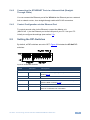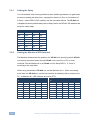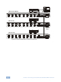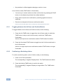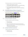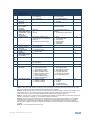
1
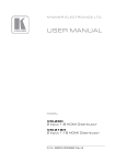
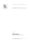
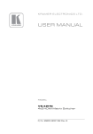
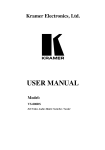
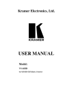
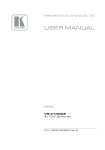
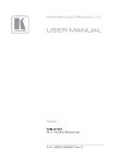
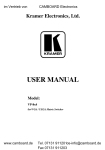
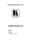
K R AM ER ELECTRONICS LTD. USER MANUAL MODEL: VP-8x8 8x8 VGA/UXGA Matrix Switcher P/N: 2900-000054 Rev 4 Contents 1 Introduction 1 2 2.1 Getting Started Achieving the Best Performance 2 2 3 3.1 3.2 Overview Defining the VP-8x8 8x8 VGA/UXGA Matrix Switcher Using the IR Transmitter 3 3 6 4 Installing in a Rack 7 5 5.1 5.2 5.3 5.4 5.5 5.6 Connecting the VP-8x8 8x8 VGA/UXGA Matrix Switcher Connecting the VP-8x8 Rear Panel Connecting a PC Controlling via RS-485 Control Configuration via the Ethernet Port Setting the DIP-Switches Cascading Machines 8 8 9 10 11 13 15 6 6.1 6.2 6.3 6.4 6.5 Operating the VP-8x8 8x8 VGA/UXGA Matrix Switcher Displaying Unit Characteristics Confirming Settings Storing/Recalling Input/Output Configurations Locking the Front Panel Updating the VP-8x8 Firmware 17 17 17 19 20 21 7 Technical Specifications 22 8 Table of Hex Codes for Serial Communication 23 9 Kramer Protocol 2000 24 Figures Figure 1: VP-8x8 8x8 VGA/UXGA Matrix Switcher Figure 2: VP-8x8 Underside View Figure 3: Connecting the VP-8x8 8x8 VGA / UXGA Matrix Switcher Figure 4: Crossed Cable RS-232 Connection Figure 5: Straight Cable RS-232 Connection with a Null Modem Adapter Figure 6: Local Area Connection Properties Window Figure 7: Internet Protocol (TCP/IP) Properties Window Figure 8: VP-8x8 DIP-switches Figure 9: Control Configuration via RS-232 and RS-485 Figure 10: Storing and Recalling using the Input/Output Buttons 4 6 9 10 10 12 12 13 16 19 VP-8x8 – Contents i 1 Introduction Welcome to Kramer Electronics! Since 1981, Kramer Electronics has been providing a world of unique, creative, and affordable solutions to the vast range of problems that confront the video, audio, presentation, and broadcasting professional on a daily basis. In recent years, we have redesigned and upgraded most of our line, making the best even better! Our 1,000-plus different models now appear in 11 groups that are clearly defined by function: GROUP 1: Distribution Amplifiers; GROUP 2: Switchers and Matrix Switchers; GROUP 3: Control Systems; GROUP 4: Format/Standards Converters; GROUP 5: Range Extenders and Repeaters; GROUP 6: Specialty AV Products; GROUP 7: Scan Converters and Scalers; GROUP 8: Cables and Connectors; GROUP 9: Room Connectivity; GROUP 10: Accessories and Rack Adapters; and GROUP 11: Sierra Products. Congratulations on purchasing your Kramer VP-8x8 8x8 VGA/UXGA Matrix Switcher, which is ideal for the following typical applications: • Any professional display system requiring a true 8x8 computer graphics matrix operation • Multimedia and presentation source, and acceptor selection VP-8x8 - Introduction 1 2 Getting Started We recommend that you: • Unpack the equipment carefully and save the original box and packaging materials for possible future shipment • Review the contents of this user manual • Use Kramer high performance high resolution cables • Use only the power cord that is supplied with this machine i 2.1 Go to http://www.kramerelectronics.com to check for up-to-date user manuals, application programs, and to check if firmware upgrades are available (where appropriate). Achieving the Best Performance To achieve the best performance: • Use only good quality connection cables to avoid interference, deterioration in signal quality due to poor matching, and elevated noise levels (often associated with low quality cables) • Avoid interference from neighboring electrical appliances that may adversely influence signal quality • Position your Kramer VP-8x8 away from moisture, excessive sunlight and dust 2 VP-8x8 - Getting Started 3 Overview The VP-8x8 is a high performance 8x8 RGBHV Matrix Switcher for high-resolution video. The VP-8x8 lets you simultaneously route any or all of the 8 inputs to any or all of the 8 outputs. The VP-8x8 8x8 VGA/UXGA Matrix Switcher features: • 400MHz video bandwidth that ensures transparent performance even in the most critical applications • 16 preset memory locations for quick access to common configurations • Delayed switching mode (ranging from 0 to 3.5sec in increments of 0.5 sec) for clean transitions (seamless switching) when switching between non-genlocked sources • DC coupled inputs and outputs • A TAKE button that allows you to place multiple switches in a queue and then activate them simultaneously with one touch of this button • A LOCK button to prevent tampering with the front panel • Automatic detection of connected input signals (respective button illuminates) Control the VP-8x8 using the front panel buttons, or remotely via: • RS-485 or RS-232 serial commands transmitted by a touch screen system, PC, or other serial controller • The Kramer RC-IR3 infrared remote control transmitter • Ethernet The VP-8x8 is dependable, rugged, and fits into one vertical space (1U) of a standard 19” professional rack. 3.1 Defining the VP-8x8 8x8 VGA/UXGA Matrix Switcher This section defines the VP-8x8. VP-8x8 - Overview 3 Figure 1: VP-8x8 8x8 VGA/UXGA Matrix Switcher 4 VP-8x8 - Overview # Feature Function 1 IR Receiver The yellow LED is illuminated when receiving signals from the infrared remote control transmitter 2 POWER Switch Illuminated switch for turning the unit ON or OFF 3 IN SELECTOR Buttons Select the input to switch to the output. When a signal is detected, the input button illuminates in green 4 OUT SELECTOR Buttons Select the output to which the input is switched 5 ALL Button Pressing ALL followed by an INPUT button, connects that input to all outputs For example, press ALL and then Input button # 2 to connect input # 2 to all the outputs 6 OFF Button Press an OUT SELECTOR button and then an OFF button to disconnect that output from the inputs Press the ALL button and then the OFF button to disconnect all the outputs 7 TAKE Button Pressing TAKE toggles the mode between the Confirm mode and the At Once mode (user confirmation per action is unnecessary) 8 STO (Store) Button Pressing STO followed by an input/output button stores the current setting When in the Confirm mode, the TAKE button illuminates For example, press STO and then the Output button # 3 to store in Setup #3 9 RCL (Recall) Button Pressing the RCL button and the corresponding IN/OUT button recalls a setup from the non-volatile memory. The stored status blinks. Pressing a different IN/OUT button lets you view another setup. After making your choice, pressing the RCL button again implements the new status 10 LOCK Button Disengages the front panel switches 11 STATUS 7-segment Display Displays the selected input switched to the output (marked above each input) Also displays the number of IN and OUT ports, the firmware version number, and the MACHINE #. Refer to section 6.1 12 15-pin HD INPUT Connectors 13 15-pin HD OUTPUT Connectors Connect to the video sources (from 1 to 8) Connect to the output acceptor (from 1 to 8) 14 FLASH PROG Button Push in for “Program” to upgrade to the latest Kramer firmware, or release for Normal (the factory default) 15 RS-232 9-pin D-sub Port Connects to the PC or the Remote Controller 16 DELAY and SETUP DIPswitches DIP-switches for setup of the unit (DELAY dips 1, 2, 3 are for setting the delay time; SETUP dips 1, 2, 3, 4 are for setting machine #; 8 is for RS-485 Termination) 17 ETHERNET Connector Connects to the PC or other Serial Controller through computer networking 18 REMOTE IR 3.5mm Mini Jack Connect to an external IR receiver unit for controlling the machine via an IR remote controller (instead of using the front panel IR receiver) The FLASH PROG “Reset” button is located on the underside of the unit Optional. Can be used instead of the front panel (built-in) IR receiver to remotely control the machine (only if the internal IR connection cable has been installed) 19 RS-485 Terminal Block Port Pin G is for Ground connection; Pins B (-) and A (+) are for RS-485 20 Power Connector with Fuse AC connector enabling power supply to the unit VP-8x8 - Overview 5 Figure 2 illustrates and defines the underside of the VP-8x8 unit. Feature Function RESET FOR PROGRAM Button Press to reset unit prior to firmware upgrade Figure 2: VP-8x8 Underside View 3.2 Using the IR Transmitter You can use the RC-IR3 IR transmitter to control the machine via the built-in IR receiver on the front panel or, instead, via an optional external IR receiver (P/N: C-A35M/IRR-50). The external IR receiver can be located 15 meters away from the machine. This distance can be extended to up to 60 meters when used with three extension cables (P/N: C-A35M/A35F-50). Before using the external IR receiver, be sure to arrange for your Kramer dealer to insert an internal IR connection cable (P/N: 505-70434010-S), which is required so that the REMOTE IR 3.5mm connector can be used. Connect the external IR receiver to the REMOTE IR 3.5mm connector. Control the matrix switcher using the front panel buttons, or remotely via the Kramer RC-IR3 Infrared Remote Control Transmitter, via an external remote IR receiver (optional), or via RS-485 or RS-232 serial commands transmitted by a touch screen system, PC, or other serial controller. 6 VP-8x8 - Overview 4 Installing in a Rack VP-8x8 - Installing in a Rack 7 5 Connecting the VP-8x8 8x8 VGA/UXGA Matrix Switcher i Always switch off the power to each device before connecting it to your VP-8x8. After connecting your VP-8x8, connect its power and then switch on the power to each device. This section describes how to: • • Connect the VP-8x8 rear panel (see section 5.1) Connect the VP-8x8 to a controlling device via RS-232 (see section 5.2), RS-485 (see section 5.3) and/or the Ethernet (see section 5.4) 5.1 • Set the DIP-switches (see section 5.5) • Connect several VP-8x8 machines (see section 5.6) Connecting the VP-8x8 Rear Panel To connect the VP-8x8, do the following: Switch OFF the power on each device before connecting it to your VP-8x8. After connecting your VP-8x8, switch on its power and then switch on the power on each device. DO NOT push in the rear panel Flash Program “Program” button (item 14 in Figure 1) and DO NOT push in the underside Flash Program “Reset” button. These are only used for upgrading to the latest Kramer firmware. 1. Connect up to 8 VGA/UXGA computer graphics sources to the input connectors (see the example in Figure 3). 2. Connect the 8 output connectors to up to 8 VGA/UXGA video acceptors. When less than eight outputs are required, connect only those outputs of the VP-8x8 that are required, and leave the other outputs unconnected 3. Set the DIP-switches (see section 5.4). 4. Connect a PC and/or controller (if required) to the RS-232 port (see section 5.2) and/or RS-485 port (see section 5.3). 5. Connect the power cord (not shown in Figure 3). 8 VP-8x8 - Connecting the VP-8x8 8x8 VGA/UXGA Matrix Switcher INP UT 1 INP UT 3 INP UT 5 INP UT 6 INP UT 7 INP UT 8 OU TP UT 1 OU TP UT 2 OU TP UT 3 OU TP UT 4 VGA OU TP UT 5 OU TP UT 6 OU TP UT 7 OU TP UT 8 RS -23 2 RS-485 Term INP UT 4 Flash Prog INP UT 2 Eth ern REM OTE et IR RS -48 5 GA Computer Graphics Source 1 B VGA VGA RS-232 Display 1 VGA Computer Graphics Source 8 Display 8 Figure 3: Connecting the VP-8x8 8x8 VGA / UXGA Matrix Switcher 5.2 Connecting a PC You can connect to the unit via a crossed RS-232 connection, using for example, a PC. A crossed cable or null-modem is required as shown in method A and B respectively. If a shielded cable is used, connect the shield to pin 5. Method A (Figure 4)—Connect the RS-232 9-pin D-sub port on the unit via a crossed cable (only pin 2 to pin 3, pin 3 to pin 2, and pin 5 to pin 5 need be connected) to the RS-232 9-pin D-sub port on the PC. Note: There is no need to connect any other pins. VP-8x8 - Connecting the VP-8x8 8x8 VGA/UXGA Matrix Switcher 9 5 4 3 2 9 8 7 6 9 8 7 6 1 5 4 3 2 PC 1 Figure 4: Crossed Cable RS-232 Connection Hardware flow control is not required for this unit. In the rare case where a controller requires hardware flow control, short pin 1 to 7 and 8, and pin 4 to 6 on the controller side. Method B (Figure 5)—Connect the RS-232 9-pin D-sub port on the unit via a straight (flat) cable to the null-modem adapter, and connect the null-modem adapter to the RS-232 9-pin D-sub port on the PC. The straight cable usually contains all nine wires for a full connection of the D-sub connector. Because the null-modem adapter (which already includes the flow control jumpering described in Method A above) only requires pins 2, 3 and 5 to be connected, you are free to decide whether to connect only these 3 pins or all 9 pins. 9 8 7 6 5 4 3 2 Null-Modem Adapter to PC 1 Figure 5: Straight Cable RS-232 Connection with a Null Modem Adapter 5.3 Controlling via RS-485 You can operate the VP-8x8 via the RS-485 port from a distance of up to 1200m (3900ft) using any device equipped with an RS-485 port (for example, a PC). For successful communication, you must set the RS-485 machine number and bus termination. To connect a device with a RS-485 port to the product: • Connect the A (+) pin on the RS-485 port of the PC to the A (+) pin on the RS-485 port on the rear panel of the VP-8x8 10 VP-8x8 - Connecting the VP-8x8 8x8 VGA/UXGA Matrix Switcher • Connect the B (–) pin on the RS-485 port of the PC to the B (–) pin on the RS-485 port on the rear panel of the VP-8x8 • If needed, connect the G pin on the RS-485 port of the PC to the G pin on the RS-485 port on the rear panel of the VP-8x8 • Set the VP-8x8 unit as Machine # 1, according to section 5.4 (that is, DIP 1, DIP 2, DIP 3, and DIP 4 OFF), and set the other DIP-switches on the VP8x8 unit, as follows: 5.4 Set DIP 5, DIP 6, and DIP 7 OFF Set DIP 8 ON (for RS-485 line termination with 120Ω) Control Configuration via the Ethernet Port You can connect the VP-8x8 via the Ethernet, using a crossover cable (see section 5.4.1) for direct connection to the PC or a straight through cable (see section 5.4.2) for connection via a network hub or network router. After connecting the Ethernet port, you have to install and configure your Ethernet Port and also install the COM Port Redirector. For detailed instructions, see the “Ethernet Configuration (Lantronix) guide.pdf” file in the technical support section on our Web site: http://www.kramerelectronics.com 5.4.1 Connecting the ETHERNET Port directly to a PC (Crossover Cable) You can connect the Ethernet port of the VP-8x8 to the Ethernet port on your PC, via a crossover cable with RJ-45 connectors. This type of connection is recommended for identification of the factory default IP Address of the VP-8x8 during the initial configuration After connecting the Ethernet port, configure your PC as follows: 1. Right-click the My Network Places icon on your desktop. 2. Select Properties. 3. Right-click Local Area Connection Properties. 4. Select Properties. The Local Area Connection Properties window appears. VP-8x8 - Connecting the VP-8x8 8x8 VGA/UXGA Matrix Switcher 11 5. Select the Internet Protocol (TCP/IP) and click the Properties Button (see Figure 6). Figure 6: Local Area Connection Properties Window 6. Select Use the following IP Address, and fill in the details as shown in Figure 7. 7. Click OK. Figure 7: Internet Protocol (TCP/IP) Properties Window 12 VP-8x8 - Connecting the VP-8x8 8x8 VGA/UXGA Matrix Switcher 5.4.2 Connecting the ETHERNET Port via a Network Hub (StraightThrough Cable) You can connect the Ethernet port of the VP-8x8 to the Ethernet port on a network hub or network router, via a straight-through cable with RJ-45 connectors. 5.4.3 Control Configuration via the Ethernet Port To control several units via the Ethernet, connect the Master unit (MACH NO. 1) via the Ethernet port to the LAN port of your PC. Use your PC initially to configure the settings (see section 5.4). 5.5 Setting the DIP-Switches By default, all DIP-switches are set to OFF. Figure 8 illustrates the VP-8x8 DIPswitches: Figure 8: VP-8x8 DIP-switches DIPS Function Description 1, 2, 3 DELAY Determines switching delay time (see the table in section 5.5.1) 4 Reserved Set to OFF Machine # Determines the number of the machine in the sequence (see the table in section 5.5.2) DELAY SETUP 1, 2, 3, 4 5, 6, 7 Reserved Set to OFF 8 RS-485 TERM ON for RS-485 Line Termination with 120Ω; OFF for no RS-485 Line Termination VP-8x8 - Connecting the VP-8x8 8x8 VGA/UXGA Matrix Switcher 13 5.5.1 Setting the Delay You can achieve clean-looking transitions when switching between non-genlocked sources by setting the delay time—ranging from 0sec to 3.5sec (in increments of 0.5sec)—via the DELAY DIP-switches, as the next table defines. The VP-8x8 unit is shipped (its factory default state) with no delay, that is, the DELAY DIP-switches are set up for a 0sec delay. 5.5.2 SEC DIP 1 DIP 2 DIP 3 0 OFF OFF OFF 0.5 OFF OFF ON 1.0 OFF ON OFF 1.5 OFF ON ON 2.0 ON OFF OFF 2.5 ON OFF ON 3.0 ON ON OFF 3.5 ON ON ON Setting the Machine # DIP-Switches The Machine # determines the position of a VP-8x8 unit, specifying which VP-8x8 unit is being controlled when several VP-8x8 units connect to a PC or serial controller. Set the Machine # on a VP-8x8 unit via Setup DIPS 1, 2, 3 and 4, according to the next table. When using a standalone VP-8x8 unit, set the Machine # to 1. When connecting more than one VP-8x8 unit, set the first machine (the Master) that is closest to the PC, as Machine # 1 (DIP-switches are set to OFF). 14 Mach # DIP 1 DIP 2 DIP 3 DIP 4 1 OFF OFF OFF OFF 9 ON OFF OFF OFF 2 OFF OFF OFF ON 10 ON OFF OFF ON Mach # DIP 1 DIP 2 DIP 3 DIP 4 3 OFF OFF ON OFF 11 ON OFF ON OFF 4 OFF OFF ON ON 12 ON OFF ON ON 5 OFF ON OFF OFF 13 ON ON OFF OFF 6 OFF ON OFF ON 14 ON ON OFF ON 7 OFF ON ON OFF 15 ON ON ON OFF 8 OFF ON ON ON 16 ON ON ON ON VP-8x8 - Connecting the VP-8x8 8x8 VGA/UXGA Matrix Switcher 5.6 Cascading Machines You can cascade up to 16 VP-8x8 units with control from a PC or serial controller (see Figure 9). To cascade up to 16 individual VP-8x8 units via RS-485, do the following: 1. Connect the VGA/UXGA sources and acceptors, as section 5.1 describes. 2. Connect the RS-232 port onto the first VP-8x8 unit to the PC using the nullmodem adapter provided with the machine (recommended), as section 5.2 describes. Alternatively, the RS-485 port could be used for PC control (instead of RS-232) 3. Connect the RS-485 terminal block port on the first unit to the RS-485 port on the second VP-8x8 unit and so on, connecting all the RS-485 ports. 4. Set the DIP-switches, as section 5.4 describes: Set the first VP-8x8 unit as Machine # 1 and the following 15 VP-8x8 units as Machine # 2 to Machine # 16 Set DIP 8 ON on the first and last VP-8x8 units (terminating the RS-485 line at 120Ω). Set DIP 8 OFF on the other VP-8x8 units Set DIP 5, DIP 6 and DIP 7 OFF on all VP-8×8 units VP-8x8 - Connecting the VP-8x8 8x8 VGA/UXGA Matrix Switcher 15 Machine # 1 (Master) Machine # 2 Up to 16 Units Machine # 16 Figure 9: Control Configuration via RS-232 and RS-485 16 VP-8x8 - Connecting the VP-8x8 8x8 VGA/UXGA Matrix Switcher 6 Operating the VP-8x8 8x8 VGA/UXGA Matrix Switcher You can operate your VP-8x8 via: • The front panel buttons • RS-232/RS-485 serial commands transmitted by a touch screen system, PC, or other serial controller 6.1 • The Kramer RC-IR3 Infrared Remote Control Transmitter • The Ethernet Displaying Unit Characteristics The STATUS 7-segment display shows two sets of information, as defined in the following table: The STATUS Display Shows: First Display 1.0 0 1 Firmware version # Immediately (and automatically) after switching on the power When simultaneously pressing, for 3 seconds, the 3 “IN” buttons 1, 2 and 3 Normal display: Inputs switched to the outputs During normal operation, appears a few seconds after the first display Machine # Second Display 6 input 6 is connected to output 3 6.2 When: Unit characteristics: Firmware version Machine number 8 input 8 is connected to output 8 The “First Display” appears initially, followed a few seconds later by the “Second Display” Confirming Settings You can choose to work in the At Once or the Confirm mode. In the At Once mode (the TAKE button is not illuminated): • Pressing an OUT-IN combination implements the switch immediately • You save time as execution is immediate and actions require no user confirmation VP-8x8 - Operating the VP-8x8 8x8 VGA/UXGA Matrix Switcher 17 • No protection is offered against changing an action in error In the Confirm mode (TAKE button is illuminated): • You can key-in several actions and then confirm them by pressing the TAKE button, to simultaneously activate the multiple switches • Every action requires user confirmation, protecting against erroneous switching • Execution is delayed until the user confirms the action Failure to press the TAKE button within one minute (the Timeout) will abort the action 6.2.1 Toggling between the At Once and Confirm Modes To toggle between the At Once and Confirm modes, do the following: 1. Press the dim TAKE button to toggle from the At Once mode (in which the TAKE button is dim) to the Confirm mode (in which the TAKE button illuminates). Actions now require user confirmation and the TAKE button illuminates. 2. Press the illuminated TAKE button to toggle from the Confirm mode back to the At Once mode. Actions no longer require user confirmation and the TAKE button no longer illuminates. 6.2.2 Confirming a Switching Action To confirm a switching action (in the Confirm mode), do the following: 1. Press an OUT-IN combination. The corresponding 7-segment Display blinks. The TAKE button also blinks. 2. Press the blinking TAKE button to confirm the action. The corresponding 7-segment Display no longer blinks. The TAKE button illuminates. 18 VP-8x8 - Operating the VP-8x8 8x8 VGA/UXGA Matrix Switcher To confirm several actions (in the Confirm mode), do the following: 1. Press each OUT-IN combination in sequence. The corresponding 7-segment Display blinks. The TAKE button also blinks. 2. Press the blinking TAKE button to confirm all the actions. The corresponding 7-segment Display no longer blinks. The TAKE button illuminates. 6.3 Storing/Recalling Input/Output Configurations You can store and recall up to 16 input/output configurations using the 8 input buttons and the 8 output buttons, as Figure 10 illustrates: Figure 10: Storing and Recalling using the Input/Output Buttons 6.3.1 Storing an Input/Output Configuration To store the current status in memory, do the following: 1. Press the STO button. The STO button blinks. 2. Press one of the 16 INPUT/OUTPUT buttons (this will be the setup # in which the current status is stored). If in the Confirm mode, press the blinking TAKE button to confirm the action. The memory stores the data at that reference. 6.3.2 Recalling an Input/Output Configuration To recall an input/output configuration, do the following: 1. Press the RCL button. The RCL button blinks. VP-8x8 - Operating the VP-8x8 8x8 VGA/UXGA Matrix Switcher 19 2. Press the appropriate INPUT/OUTPUT button (the button # corresponding to the setup #). If in the Confirm mode, that setup configuration will blink in the 7-segment Display, together with the RCL button and the TAKE button, and will only be implemented after pressing the TAKE button. The memory recalls the stored data from that reference. Tip: If you cannot remember which of the 16 input/output configurations is the one that you want, set the VP-8x8 to the Confirm mode and manually scan all the input/output configurations until you locate it. 6.3.3 Deleting an Input/Output Configuration To delete an input/output configuration, do the following: 1. Press the STO and RCL buttons simultaneously. Both the STO and RCL buttons blink. 2. Press the appropriate INPUT/OUTPUT button. This erases that specific input/output configuration from the memory, leaving it empty and available. Storing a new configuration over a previous configuration (without deleting it first) replaces the previous configuration 6.4 Locking the Front Panel To prevent changing the settings accidentally or tampering with the unit via the front panel buttons, lock your VP-8x8. Unlocking releases the protection mechanism. Nevertheless, even though the front panel is locked you can still operate via RS-232 or RS-485, as well as via the Kramer RC-IR3 Infrared Remote Control Transmitter To lock the VP-8x8: • Press the LOCK button for more than two seconds, until the LOCK button is illuminated. The front panel is locked. Pressing a button will have no effect other than causing the LOCK button to flash Warning that you need to unlock to regain control via the front panel To unlock the VP-8x8: • Press the illuminated LOCK button for more than two seconds, until the LOCK button is no longer illuminated, the front panel unlocks 20 VP-8x8 - Operating the VP-8x8 8x8 VGA/UXGA Matrix Switcher 6.5 Updating the VP-8x8 Firmware The VP-8x8 functions by means of a device microcontroller that runs firmware located in FLASH memory. If required, you can download and install the latest firmware version from the Kramer Web site (www.kramerelectronics.com). VP-8x8 - Operating the VP-8x8 8x8 VGA/UXGA Matrix Switcher 21 7 Technical Specifications INPUTS: 8 VGA on 15-pin HD connectors (VGA through UXGA) OUTPUTS: 8 VGA on 15-pin HD connectors (VGA through UXGA) MAX. OUTPUT LEVEL: 1.5Vpp BANDWIDTH (-3dB): 400MHz DIFF. GAIN: 0.04% DIFF. PHASE: 0.04Deg. K-FACTOR: <0.05% S/N RATIO: 75dB CROSSTALK (all hostile): –53dB CONTROLS: 22 front panel buttons, RS-232, RS-485, Ethernet COUPLING: DC OPERATING TEMPERATURE: STORAGE TEMPERATURE: HUMIDITY: 0° to +55°C (32° to 131°F) POWER SOURCE: 100-264V AC, 50/60 Hz; 23VA -45° to +72°C (-49° to 162°F) 10% to 90%, RHL non-condensing DIMENSIONS: 19” x 7” x 1U (W, D, H) rack-mountable WEIGHT: 2.7kg (6lbs) approx. ACCESSORIES: Power cord, null modem adapter, Windows®-based Kramer control software, infrared remote control transmitter OPTIONS: External remote IR receiver cable P/N: C-A35M/IRR-50 Specifications are subject to change without notice For the most updated resolution list, go to our Web site at http://www.kramerelectronics.com 22 VP-8x8 - Technical Specifications 8 Table of Hex Codes for Serial Communication The following table lists the Hex values for a single machine (MACHINE # 1): Switching Video Channels OUT 1 IN 1 IN 2 IN 3 IN 4 IN 5 IN 6 IN 7 IN 8 01 81 81 81 01 82 81 81 01 83 81 81 01 84 81 81 01 85 81 81 01 86 81 81 01 87 81 81 01 88 81 81 OUT 2 01 81 82 81 01 82 82 81 01 83 82 81 01 84 82 81 01 85 82 81 01 86 82 81 01 87 82 81 01 88 82 81 OUT 3 01 81 83 81 01 82 83 81 01 83 83 81 01 84 83 81 01 85 83 81 01 86 83 81 01 87 83 81 01 88 83 81 OUT 4 01 81 84 81 01 82 84 81 01 83 84 81 01 84 84 81 01 85 84 81 01 86 84 81 01 87 84 81 01 88 84 81 VP-8x8 - Table of Hex Codes for Serial Communication OUT 5 01 81 85 81 01 82 85 81 01 83 85 81 01 84 85 81 01 85 85 81 01 86 81 81 01 87 85 81 01 88 85 81 OUT 6 01 81 86 81 01 82 86 81 01 83 86 81 01 84 86 81 01 85 86 81 01 86 82 81 01 87 86 81 01 88 86 81 OUT 7 01 81 87 81 01 82 87 81 01 83 87 81 01 84 87 81 01 85 87 81 01 86 83 81 01 87 87 81 01 88 87 81 OUT 8 01 81 88 81 01 82 88 81 01 83 88 81 01 84 88 81 01 85 88 81 01 86 84 81 01 87 88 81 01 88 88 81 23 9 Kramer Protocol 2000 The VP-8x8 is compatible with Kramer’s Protocol 2000 described below. This RS-232/ RS-485 communication protocol uses four bytes of information as defined below. For RS-232, a null-modem connection between the machine and controller is used. The default data rate is 9600 baud, with no parity, 8 data bits and 1 stop bit. You can download our user-friendly “Software for Calculating Hex Codes for Protocol 2000” from the technical support section on our Web site at: http://www.kramerelectronics.com 1st byte DESTINATION INSTRUCTION 0 7 D 6 N5 5 N4 4 N3 3 N2 2 N1 1 N0 0 2nd byte INPUT 1 7 I6 6 I5 5 I4 4 I3 3 I2 2 I1 1 I0 0 3d byte OUTPUT 1 7 O6 6 O5 5 O4 4 O3 3 O2 2 O1 1 O0 0 OVR 6 X 5 M2 2 M1 1 M0 0 4th byte 1 7 MACHINE NUMBER M4 4 M3 3 1st BYTE: Bit 7 – Defined as 0. D – “DESTINATION”: 0 - for sending information to the switchers (from the PC); 1 - for sending to the PC (from the switcher). N5…N0 – “INSTRUCTION” The function that is to be performed by the switcher(s) is defined by the INSTRUCTION (6 bits). Similarly, if a function is performed via the machine’s keyboard, then these bits are set with the INSTRUCTION NO., which was performed. The instruction codes are defined according to the table below (INSTRUCTION NO. is the value to be set for N5…N0). 2nd BYTE: Bit 7 – Defined as 1. I6…I0 – “INPUT”. When switching (ie. instruction codes 1 and 2), the INPUT (7 bits) is set as the input number which is to be switched. Similarly, if switching is done via the machine’s front-panel, then these bits are set with the INPUT NUMBER which was switched. For other operations, these bits are defined according to the table. 3rd BYTE: Bit 7 – Defined as 1. O6…O0 – “OUTPUT”. When switching (ie. instruction codes 1 and 2), the OUTPUT (7 bits) is set as the output number which is to be switched. Similarly, if switching is done via the machine’s front-panel, then these bits are set with the OUTPUT NUMBER which was switched. For other operations, these bits are defined according to the table. 4th BYTE: Bit 7 – Defined as 1. Bit 5 – Don’t care. OVR – Machine number override. M4…M0 – MACHINE NUMBER. Used to address machines in a system via their machine numbers. When several machines are controlled from a single serial port, they are usually configured together with each machine having an individual machine number. If the OVR bit is set to 1, then all machine numbers will accept (implement) the command, and only the addressed machine will reply. For a single machine controlled via the serial port, always set M4…M0 = 00001, and make sure that the machine itself is configured as MACHINE NUMBER = 1. Note: All values in the table are decimal, unless otherwise stated. 24 VP-8x8 - Kramer Protocol 2000 INSTRUCTION DEFINITION FOR SPECIFIC INSTRUCTION NOTE # DESCRIPTION INPUT OUTPUT 0 1 RESET VIDEO SWITCH VIDEO STORE VIDEO STATUS RECALL VIDEO STATUS REQUEST STATUS OF A VIDEO OUTPUT REQUEST WHETHER SETUP IS DEFINED / VALID INPUT IS DETECTED ERROR / BUSY 0 Set equal to video output which is to be switched (0 = to all the outputs) 0 - to store 1 - to delete 0 1 2, 15 3 0 Set equal to video input which is to be switched (0 = disconnect) Set as SETUP # Set as SETUP # Equal to output number whose status is required 4, 3 SETUP # or Input # 0 - for checking if setup is defined 1 - for checking if input is valid 8 For invalid / valid input (i.e. OUTPUT byte = 4 or OUTPUT byte = 5), this byte is set as the input # 9, 25 10 2, 3 4 5 15 16 17 20 30 31 32 to 35 57 Set as SETUP # 2, 3, 15 2, 3, 15 RESERVED RECALL AUDIO STATUS LOCK FRONT PANEL REQUEST WHETHER PANEL IS LOCKED RESERVED ---Set as SETUP # 0 - error 1 - invalid instruction 2 - out of range 3 - machine busy 4 - invalid input 5 - valid input ---0 0 - Panel unlocked 1 - Panel locked 0 0 2 0 16 ---- ---- 10 SET AUTO-SAVE I3 - no save I4 - auto-save (127 = load SETUP #) 1 - video machine name 2 - audio machine name 3 - video software version 4 - audio software version 5 - RS422 controller name 6 - RS422 controller version 7 - remote control name 8 - remote software version 9 - Protocol 2000 revision 1 - number of inputs 2 - number of outputs 3 - number of setups 0 12, 2 61 IDENTIFY MACHINE 62 DEFINE MACHINE or SETUP # 0 - Request first 4 digits 1 - Request first suffix 2 - Request second suffix 3 - Request third suffix 10 - Request first prefix 11 - Request second prefix 12 - Request third prefix 1 - for video 2 - for audio 3 - for SDI 4 - for remote panel 5 - for RS-422 controller 13 14 NOTES on the above table: NOTE 1 - When the master switcher is reset, (e.g. when it is turned on), the reset code is sent to the PC. If this code is sent to the switchers, it will reset according to the present power-down settings. NOTE 5 – For the OUTPUT byte set as 6, the VIS source is the input selected using the OUTPUT byte. Similarly, for the OUTPUT byte set as 7, the VIS source is the output selected using the OUTPUT byte. Note also, that on some machines the sync source is not software selectable, but is selected using switches, jumpers, etc! NOTE 8 - The reply is as in TYPE 3 above, except that here the OUTPUT is assigned with the value 0 if the setup is not defined / no valid input is detected; or 1 if it is defined / valid input is detected. NOTE 9 - An error code is returned to the PC if an invalid instruction code was sent to the switcher, or if a parameter associated with the instruction is out of range (e.g. trying to save to a setup greater than the highest one, or trying to switch an input or output greater than the highest one defined). This code is also returned to the PC if an RS-232 instruction is sent while the machine is being programmed via the front panel. Reception of this code by the switcher is not valid. NOTE 10 – This code is reserved for internal use. VP-8x8 - Kramer Protocol 2000 25 NOTE 12 - Under normal conditions, the machine's present status is saved each time a change is made. The "powerdown" save (auto-save) may be disabled using this code. Note that whenever the machine is turned on, the auto-save function is set. NOTE 13 - This is a request to identify the switcher/s in the system. If the OUTPUT is set as 0, and the INPUT is set as 1, 2, 5 or 7, the machine will send its name. The reply is the decimal value of the INPUT and OUTPUT. For example, for a 2216, the reply to the request to send the audio machine name would be (HEX codes): 7D 96 90 81 (i.e. 128dec+ 22dec for 2nd byte, and 128dec+ 16dec for 3rd byte). If the request for identification is sent with the INPUT set as 3 or 4, the appropriate machine will send its software version number. Again, the reply would be the decimal value of the INPUT and OUTPUT - the INPUT representing the number in front of the decimal point, and the OUTPUT representing the number after it. For example, for version 3.5, the reply to the request to send the version number would be (HEX codes): 7D 83 85 81 (i.e. 128dec+ 3dec for 2nd byte, 128dec+ 5dec for 3rd byte). If the OUTPUT is set as 1, then the ASCII coding of the lettering following the machine’s name is sent. For example, for the VS-7588YC, the reply to the request to send the first suffix would be (HEX codes): 7D D9 C3 81 (i.e. 128dec+ ASCII for “Y”; 128dec+ ASCII for “C”). NOTE 14 - The number of inputs and outputs refers to the specific machine which is being addressed, not to the system. For example, if six 16X16 matrices are configured to make a 48X32 system (48 inputs, 32 outputs), the reply to the HEX code 3E 82 81 82 (ie. request the number of outputs) would be HEX codes 7E 82 90 82 ie. 16 outputs NOTE 16 - The reply to the “REQUEST WHETHER PANEL IS LOCKED” is as in NOTE 4 above, except that here the OUTPUT is assigned with the value 0 if the panel is unlocked, or 1 if it is locked. NOTE 21 – To store data in the non-volatile memory of the unit, eg. the EEPROM for saving SETUPS. The EEPROM address is sent using the INPUT byte, and the data to be stored is sent using the OUTPUT byte. To use this instruction, it is necessary to understand the memory map, and memory structure of the particular machine. NOTE 25 – For units which detect the validity of the video inputs, Instruction 16 will be sent whenever the unit detects a change in the state of an input (in real-time). For example, if input 3 is detected as invalid, the unit will send the HEX codes 10 83 84 81 If input 7 is detected as valid, then the unit will send HEX codes 10 87 85 81. 26 VP-8x8 - Kramer Protocol 2000 LIMITED WARRANTY We warrant this product free from defects in material and workmanship under the following terms. HOW LONG IS THE WARRANTY Labor and parts are warranted for seven years from the date of the first customer purchase. WHO IS PROTECTED? Only the first purchase customer may enforce this warranty. WHAT IS COVERED AND WHAT IS NOT COVERED Except as below, this warranty covers all defects in material or workmanship in this product. The following are not covered by the warranty: 1. Any product which is not distributed by us or which is not purchased from an authorized Kramer dealer. If you are uncertain as to whether a dealer is authorized, please contact Kramer at one of the agents listed in the Web site www.kramerelectronics.com. 2. Any product, on which the serial number has been defaced, modified or removed, or on which the WARRANTY VOID IF TAMPERED sticker has been torn, reattached, removed or otherwise interfered with. 3. Damage, deterioration or malfunction resulting from: i) Accident, misuse, abuse, neglect, fire, water, lightning or other acts of nature ii) Product modification, or failure to follow instructions supplied with the product iii) Repair or attempted repair by anyone not authorized by Kramer iv) Any shipment of the product (claims must be presented to the carrier) v) Removal or installation of the product vi) Any other cause, which does not relate to a product defect vii) Cartons, equipment enclosures, cables or accessories used in conjunction with the product WHAT WE WILL PAY FOR AND WHAT WE WILL NOT PAY FOR We will pay labor and material expenses for covered items. We will not pay for the following: 1. Removal or installations charges. 2. Costs of initial technical adjustments (set-up), including adjustment of user controls or programming. These costs are the responsibility of the Kramer dealer from whom the product was purchased. 3. Shipping charges. HOW YOU CAN GET WARRANTY SERVICE 1. To obtain service on you product, you must take or ship it prepaid to any authorized Kramer service center. 2. Whenever warranty service is required, the original dated invoice (or a copy) must be presented as proof of warranty coverage, and should be included in any shipment of the product. Please also include in any mailing a contact name, company, address, and a description of the problem(s). 3. For the name of the nearest Kramer authorized service center, consult your authorized dealer. LIMITATION OF IMPLIED WARRANTIES All implied warranties, including warranties of merchantability and fitness for a particular purpose, are limited in duration to the length of this warranty. EXCLUSION OF DAMAGES The liability of Kramer for any effective products is limited to the repair or replacement of the product at our option. Kramer shall not be liable for: 1. Damage to other property caused by defects in this product, damages based upon inconvenience, loss of use of the product, loss of time, commercial loss; or: 2. Any other damages, whether incidental, consequential or otherwise. Some countries may not allow limitations on how long an implied warranty lasts and/or do not allow the exclusion or limitation of incidental or consequential damages, so the above limitations and exclusions may not apply to you. This warranty gives you specific legal rights, and you may also have other rights, which vary from place to place. NOTE : All products returned to Kramer for service must have prior approval. This may be obtained from your dealer. This equipment has been tested to determine compliance with the requirements of: EN-50081: EN-50082: CFR-47: "Electromagnetic compatibility (EMC); generic emission standard. Part 1: Residential, commercial and light industry" "Electromagnetic compatibility (EMC) generic immunity standard. Part 1: Residential, commercial and light industry environment". FCC* Rules and Regulations: Part 15: “Radio frequency devices Subpart B Unintentional radiators” CAUTION! Servicing the machines can only be done by an authorized Kramer technician. Any user who makes changes or modifications to the unit without the expressed approval of the manufacturer will void user authority to operate the equipment. Use the supplied DC power supply to feed power to the machine. Please use recommended interconnection cables to connect the machine to other components. * FCC and CE approved using STP cable (for twisted pair products) VP-8x8 - Kramer Protocol 2000 27 For the latest information on our products and a list of Kramer distributors, visit our Web site where updates to this user manual may be found. We welcome your questions, comments, and feedback. Web site: www.kramerelectronics.com E-mail: [email protected] ! SAFETY WARNING Disconnect the unit from the power supply before opening and servicing