1
Implementing Multi-Touch Screen for Real-time
Control of a Robotic cell
At
Universidad Politécnica de Valencia
Master of Science Thesis
MARTIN EDBERG
PETER NYMAN
Department of Product and Production Development
Division of Production Systems
CHALMERS UNIVERSITY OF TECHNOLOGY
Göteborg, Sweden, 2010
THESIS FOR MASTER'S DEGREE IN PRODUCTION ENGINEERING
Implementing Multi-Touch screen
for real-time control of a robotic cell
MARTIN EDBERG
PETER NYMAN
Department of Product and Production Development
Division of Production Systems
Göteborg, Sweden
I
Implementing Multi-Touch screen for real-time control of a robotic cell
MARTIN EDBERG
PETER NYMAN
Copyright © MARTIN EDBERG, PETER NYMAN, 2010.
Department of Product and Production Development
Chalmers University of Technology
SE-412 96 Göteborg
Sweden
Telephone +46(0)31-772 1000
Cover:
The cover shows a picture from the demonstrator built in the IDF laboratory, Polytechnic
University of Valencia, Spain
Printed by
Chalmers Reproservice
Göteborg, Sweden 2010
II
Implementing Multi-touch screen for real-time control of a robotic cell
MARTIN EDBERG, PETER NYMAN
Department of Product and Production Development
Division of Production Systems
Chalmers University of Technology
Abstract
Today
Multi‐touch
technology
are
being
developed
to
fit
many
different
applications
on
the
consumer
market,
but
it
is
still
something
new
and
quite
unknown
in
the
industrial
sector.
The
technology
has
expanded
a
lot
during
the
latest
years
and
compared
to
other
control
devices,
such
as
a
mouse
or
a
keyboard,
it
has
the
ability
to
allow
more
intuitivism
to
be
implemented.
The
objective
of
this
thesis
is
to
make
use
of
a
Multi‐touch
screen
to
create
an
intuitive
interface
for
industrial
robot
controlling.
An
operator
shall
be
able
to
understand
it
with
as
little
training
as
possible.
A
camera
shall
be
mounted
on
the
tip
of
the
robot
arm
and
the
robot
shall
be
completely
controlled
by
inputs
(touches,
motions
and
gestures)
made
on
the
Multi‐touch
screen.
One
example
of
application
can
be
to
use
it
for
inspection
purposes
by
integrating
the
video
stream
from
the
camera
in
the
user
interface.
The
thesis
was
performed
at
the
Department
of
Design
and
Manufacturing
(Instituto
de
Diseño
y
Fabricación)
at
the
Polytechnic
University
of
Valencia
(Universidad
Politécnica
de
Valencia)
in
Spain.
The
thesis
is
a
part
of
a
larger
project
with
the
goal
to
make
a
working
demonstrator.
Included
in
the
thesis
work
was
also
an
evaluation
of
the
whole
concept,
which
was
done
by
performing
a
series
of
different
usability
tests.
This
test
was
done
on
a
group
of
20
people
with
different
ages,
sexes
and
backgrounds.
The
results
of
the
usability
tests
showed
that
the
use
of
Multi‐touch
technology
for
controlling
industrial
robots
could
increase
the
intuitivism
of
the
user
interface
compared
to
conventional
controls.
This
conclusion
is
drawn
from
the
fact
that
all
users
were
able
to
complete
the
first
usability
test
without
any
instructions,
regardless
of
their
background.
The
test
also
showed
that
using
this
technology
could
significantly
decrease
the
learning
period
for
an
operator,
even
without
experience
of
robot
controlling
or
multi‐touch
technology.
Keywords:
Multi‐touch,
industrial
robots,
human
machine
interface,
intuitivism,
real‐time
control,
usability
III
IV
Acknowledgement
This
has
been
a
research
line
performed
at
IDF
department
at
the
UPV
University
in
Valencia,
Spain
in
cooperation
with
Department
of
Product
and
Production
development
at
Chalmers
University
of
Technology,
Gothenburg,
Sweden.
We,
Martin
Edberg
and
Peter
Nyman,
as
authors
of
this
thesis
work
are
very
thankful
to
our
supervisors
at
UPV,
Adolfo
Muñoz
Garcia
and
Josep
Tornero.
Without
your
support,
feedback
and
comments,
this
work
would
not
have
been
able
to
perform.
We
also
would
like
to
express
our
appreciation
to
our
supervisor
Per
Nyqvist,
and
examiner
Rolf
Berlin
at
Chalmers
University
of
Technology
who
have
helped
and
supported
us
throuhgout
the
project.
V
VI
Abbreviations
KRL
UDP/IP
KUKA
Robot
Language
User
Interface
Human
Machine
Interface
Extensible
Markup
Language
Robot
Sensor
Interface
High
Definition
Transmission
Control
Protocol/Internet
protocol;
Communication
protocol
for
networks
User
Datagram
Protocol
used
for
network
communication
C#
C
–
sharp,
Object‐oriented
programmation
language,
a
part
of
the
.NET
platform
UI
HMI
XML
RSI
HD
TCP/IP
End
effector
Syntax
LAN
The
"tool"
placed
on
the
end
of
the
robot
arm.
For
example
Grip‐tool
or
camera
Principles
and
rules
for
constructing
sentences
in
natural
languages.
Normally
a
simplified
description
of
a
program
Local
Area
Network
VII
VIII
Table
of
Contents
1.
Introduction ........................................................................................................................ 1
1.1
Purpose
and
objective .................................................................................................................1
1.1.1Purpose ........................................................................................................................................ 1
1.1.2
Objective ..................................................................................................................................... 1
1.2
Background .................................................................................................................................2
1.2.1
Project
background ..................................................................................................................... 2
1.3
Theory.........................................................................................................................................2
1.4
Delimitations...............................................................................................................................3
2.
Theoretical
background ....................................................................................................... 5
2.1
Industrial
robots..........................................................................................................................5
2.1.1
History ......................................................................................................................................... 5
2.2
Human
Machine
interface ...........................................................................................................6
2.3
Multi‐touch
technology ...............................................................................................................6
2.3.1
History ......................................................................................................................................... 6
2.3.2
Different
technologies................................................................................................................. 8
2.4
Robot
Control............................................................................................................................10
2.4.1
Conventional
control................................................................................................................ 10
2.4.2
Programming
of
KUKA
robots
(KRL) ......................................................................................... 11
2.4.3
Real‐time
control ...................................................................................................................... 12
2.4.4
KUKA.Ethernet
RSI
XML............................................................................................................. 12
3.
Hardware
and
software
prerequisites................................................................................ 18
3.1
Robot ........................................................................................................................................18
3.2
Robot
controller ........................................................................................................................18
3.2
Screen .......................................................................................................................................18
3.3
External
computers ...................................................................................................................19
3.4
Software....................................................................................................................................19
4
Methodology...................................................................................................................... 20
4.1
Initiation ...................................................................................................................................20
4.2
Setup.........................................................................................................................................20
4.3
Establishment
of
communication ..............................................................................................20
4.4
Interface
design.........................................................................................................................21
4.5
Concept
evaluation....................................................................................................................21
5.
System
development
process ............................................................................................ 22
5.1
Interface
Development..............................................................................................................22
5.1.1
Layout........................................................................................................................................ 28
5.1.2
Proposed
gestures..................................................................................................................... 29
5.2
Robot
Controller
Programming..................................................................................................30
5.3
Communication .........................................................................................................................34
6.
Empirical
study.................................................................................................................. 36
IX
6.1
Usability
tests............................................................................................................................36
7.
Results .............................................................................................................................. 38
8.
Discussion ......................................................................................................................... 40
9.
Conclusions ....................................................................................................................... 42
References ............................................................................................................................ 44
Appendix
A
‐
Instructions
for
usability
tests
Appendix
B
–
Tables
of
the
collected
data
from
log
files
Appendix
C
–
User
manual
for
Robotic
cell
at
IDF
Appendix
D
‐
Complete
code
for
IDF_RSI_XML.src
X
1. Introduction
1.
Introduction
Today
Multi‐touch
technology
is
being
implemented
to
fit
many
different
applications.
A
lot
of
research
is
being
done
as
the
technology
is
being
developed.
Since
the
touch
technology
allows
more
intuitivism
to
be
implemented
than
with
normal
control
devices,
such
as
a
mouse
or
keyboard,
it
is
an
interesting
area
that
has
expanded
a
lot
during
the
latest
years.
Real‐time
control
of
industrial
robots
is
today
usually
done
using
a
so
called
teach‐pendant
(see
explanation
under
the
section
”Industrial
robots”),
with
single
motions
in
directions
or
axis,
or
multiple
direction
movement
using
a
mouse.
Regarding
the
programming
there
is
often
a
need
of
experienced
programmers
to
be
able
to
move
the
robot
in
the
desired
way.
The
available
tools
for
helping
programmers
are
mostly
simulators
developed
normally
by
the
same
company
as
the
robot
manufacturer,
which
require
special
training
and
a
learning
period
before
one
can
start
using
the
software
for
its
purpose.
The
following
text
describes
the
purpose
of
the
thesis,
the
background,
the
hardware
and
software
prerequisites,
methodology,
system
development
process
and
the
empirical
study.
From
these
the
results
of
the
thesis
are
discussed
and
conclusions
are
drawn.
1.1
Purpose
and
objective
This
section
discusses
the
purpose
and
the
objective
of
this
thesis.
1.1.1Purpose
The
purpose
of
the
project
is
to
investigate
the
possibilities
with
a
Multi‐touch
screen
when
controlling
an
industrial
robot,
especially
when
used
for
inspection
purposes
like
quality
control
with
a
camera
mounted
on
the
robot
arm.
This
is
done
by
transforming
the
motions
and
gestures
of
fingers
made
on
the
screen
into
motions
of
the
robot.
1.1.2
Objective
The
objective
of
the
project
was
to
develop
a
real‐time
connection
between
a
Human‐Machine
interface
(HMI),
running
on
a
commercial
Multi‐touch
screen,
using
PQ
Labs’
overlay
on
an
industrial
full
HD
42‐inch
LG
monitor,
and
an
industrial
KUKA‐robot.
The
interface
on
the
Multi‐
touch
screen
should
be
easy
to
handle
and
display
real
time
information
about
what
is
happening
in
the
cell
such
as
the
position
of
the
robot
arm
in
space
and
tool
position.
The
outcome
of
the
project
shall
be
a
demonstrator
that
is
going
to
be
tested
and
later
investigate
its
possibilities
and
limitations.
The
Multi‐touch
screen
shall
be
evaluated
and
tested
to
see
whether
it
is
a
good
platform
for
this
type
of
control.
The
robot
shall
be
able
to
follow
a
trajectory
drawn
on
the
Multi‐touch
screen
in
both
online
and
offline
modes.
This
means
that
the
system
must
be
fail‐safe
and
not
allow
any
collisions
or
movement
that
could
cause
failures.
The
interface
on
the
Multi‐touch
screen
needs
to
have
a
design
that
is
easy
to
understand
and
has
clear
warning
signals.
Latency
and
safety
issues
must
be
considered.
In
order
to
guarantee
an
accurate
control
on
real‐time
operations,
it
is
necessary
to
retrieve
real‐time
feedback
from
the
robot
cell
to
the
Multi‐touch
user
interface.
1
1. Introduction
1.2
Background
Multi‐touch
applications
is
still
something
new
and
quite
unknown
in
the
industrial
sector.
The
technology
became
available
to
the
consumer
market
when
the
first
version
of
the
Iphone
entered
the
market
in
2007[1],
and
it
was
a
real
breakthrough
for
the
technology.
It
set
new
standards
when
it
came
to
how
to
handle
and
control
an
electronic
device.
After
that,
many
other
manufacturers
realized
that
they
also
needed
to
utilize
Multi‐touch
technology
in
order
to
stay
competitive.
Several
gestures
started
to
spread
among
different
plattforms
such
as
the
two‐finger
spread
motion
for
zooming
and
the
one
finger
drag
motion
used
for
panning.
On
the
field
of
robotics,
there
are
at
the
moment
few
examples
of
Multi‐touch
applications.
One
interesting
application
can
be
controlling
industrial
robots
used
in
production
systems.
1.2.1
Project
background
The
"Instituto
de
Diseño
y
Fabricación"
(refered
to
as
"IDF")
at
the
Universidad
Politécnica
de
Valencia
in
Spain
holds
a
new
research
line
about
Multi‐touch
control
for
industrial
applications.
The
department
has
recently
invested
in
a
42‐inch
Multi‐touch
overlay
from
PQ
labs,
a
US‐based
company
specialized
in
touch‐technology.
In
order
to
use
this
overlay
they
also
purchased
a
42‐
inch
industrial
full
HD
monitor
from
LG.
Since
the
department
has
a
KUKA
KR
5
sixx
R650
industrial
robot,
the
research
has
been
aimed
towards
the
combination
of
these
two
technologies.
The
controlling
of
robots
via
a
Multi‐touch
screen
is
a
relatively
new
application
of
use,
so
the
benefits
of
using
it
may
not
be
fully
explored.
The
Multi‐touch
interface
enables
several
inputs
to
be
done
simultaneously,
which
can
make
it
to
a
powerful
tool
when
controlling
complex
systems.
Since
the
screen
used
in
this
project
is
relatively
large
(42
inch)
it
allows
a
collaborative
UI
(user
interface)
so
that
more
than
one
people
can
be
working
on
it
at
the
same
time.
1.3
Theory
Studies
have
been
carried
out
on
how
the
communication
methods
work
and
which
was
the
best
suited
method
for
this
application.
When
it
was
decided
which
type
of
communication
method
to
use,
the
theory
was
to
learn
more
about
that
specific
method
and
its
advantages,
so
that
it
could
be
exploited
as
much
as
possible
for
this
specific
purpose.
Since
the
thesis
has
been
a
part
of
a
larger
project
(see
section
”Delimitations”),
a
lot
of
decisions
has
been
taken
through
discussions
with
all
group
members.
Regarding
the
communication,
the
KUKA
robots
understand
a
language
that
is
called
KUKA
Robot
Language
(KRL)
and
at
the
end
all
signals
needs
to
be
transformed
into
this,
so
that
the
robot
interpret
the
code
and
thus
perform
the
corresponding
motions.
2
1. Introduction
1.4
Delimitations
The
devices
to
work
with
were
one
Multi‐touch
screen
controlling
one
industrial
KUKA
robot
model
KR
5
sixx
R650.
The
tool
to
work
with
was
primarily
a
camera
used
for
inspection
of
products.
This
thesis
was
a
part
of
a
larger
project,
which
includes
programming
of
the
Multi‐
touch
screen
controls
and
graphic
design
as
well
as
the
communication
between
the
Multi‐
touch
screen
and
the
robot.
The
focus
of
this
project
was
to
establish
and
make
sure
that
the
communication
between
the
robot
and
the
computer
with
the
Multi‐touch
screen
runs
smoothly.
Specifically
this
means
taking
the
signals
from
the
Multi‐touch
screen
and
transfering
it
into
real
motions
of
the
robot.
This
means
that
programming
of
the
robot
controller
itself
was
needed.
The
actual
programming
of
the
screen
was
not
included
in
this
part
of
the
project,
but
a
good
understanding
was
necessary
to
retrieve
a
deeper
knowledge
of
the
communication
in
the
human‐machine
interface.
However
this
thesis
work
had
a
great
influence
of
the
graphic
design
since
investigating
the
Multi‐touch
screen’s
usability
is
a
part
of
the
thesis.
The
thesis
had
to
be
carried
out
and
finished
within
the
set
timeframe,
that
had
a
due
date
the
30th
of
June
2010.
3
1. Introduction
4
2. Theoretical background
2.
Theoretical
background
This
section
describes
the
theoretical
background,
first
in
general
and
then
more
detailed
about
this
specific
project.
2.1
Industrial
robots
It
has
to
be
clearly
stated
that
there
is
a
difference
between
robots
in
general
and
industrial
robots.
When
talking
about
robots
in
general,
that
includes
all
types
of
robots
which
can
have
special
purposes,
humanoids
(robots
that
are
constructed
to
act
as
a
human),
cleaning
robots,
etc.
However
this
report
focus
is
on
robots
used
within
the
industry.
By
ISO
definition
an
industrial
robot
is
an
automatically
controlled,
reprogrammable
multipurpose
manipulator
that
can
be
programmed
in
three
axes
or
more
[2].
The
expression
”field
of
robotics”
is
often
used
and
that
includes
everything
related
to
the
robots,
normally
when
used
in
industrial
appplications
typically
for
production.
Robots
can
be
adapted
and
used
for
a
lot
of
different
tasks.
Typical
applications
for
industrial
robots
can
be
welding,
assembly,
painting,
inspection
etc,
performed
at
a
high
speed
and
and
with
high
precision.
Normally
the
robot
is
connected
through
a
controller
to
a
laptop,
or
desktop
computer
in
which
the
programming
takes
place.
Almost
all
industrial
robots
come
with
a
so
called
tech‐pendant
which
can
be
used
in
order
to
move
and
control
the
robot.
In
other
words
the
robot
can
be
taught
to
go
to
specific
points
in
space
and
then
perform
the
trajectory
that
it
has
been
taught.
2.1.1
History
The
first
real
robot
patents
were
applied
by
George
Devol
in
1954
[3]
Two
years
later
the
first
robot
was
produced
by
a
company
called
Unimation,
founded
by
George
Devol
and
Joseph
F.
Engelberger.
In
these
first
machines
the
angles
of
each
joints
were
stored
during
a
teaching
phase
and
could
then
later
by
replayed.
The
accuracy
was
very
high
1/10000
of
an
inch.
Worth
to
notice
is
that
the
most
important
measure
in
robotics
is
not
accuracy,
but
repeatability.
This
is
due
to
the
fact
that
normally
the
robots
are
taught
to
do
one
task
over
and
over
again.
The
first
6‐axis
robot
was
invented
in
1969
by
Victor
Scheinman
at
Stanford
University,
named
"the
Stanford
arm"
and
could
substitute
the
motions
of
an
arm
[3].
The
Stanford
arm
made
it
possible
to
make
arbitrary
paths
in
space
and
also
permit
the
robot
to
perform
more
complicated
tasks,
such
as
welding
and
assembly.
In
Europe
the
industrial
robots
took
off
around
1973
when
both
KUKA
and
ABB
entered
the
market
and
launched
their
first
models.
Both
came
with
six
electro‐mechanically
driven
axes.
In
the
late
1970's
the
consumer
market
started
showing
interest
and
several
American
based
companies
entered
the
market.
The
real
robotics
boom
came
in
1984
when
Unimation
was
sold
to
Westinghouse
Electric
Corporation.
Few
Japanese
companies
managed
to
survive,
and
today
5
2. Theoretical background
the
major
companies
are
Adept
Technology,
Stäubli‐Unimation,
the
Swedish‐Swiss
company
ABB
Asea
Brown
Boveri
and
the
German
company
KUKA
Robotics.
2.2
Human
Machine
interface
An
interface
is
a
point
of
interactions
between
two
systems
or
work
groups,
hence
the
Human
machine
interface
(referred
as
HMI
from
here)
is
the
interaction
point
between
the
human
(in
this
case
the
user)
and
the
machine.
The
machine
can
be
all
kinds
of
electronic
devices
that
are
controlled
by
the
human
user.
A
lot
of
research
has
been
done
over
the
years
on
how
to
make
the
HMI
as
easy
and
self
explainatory
as
possible.
A
keyword
when
designing
Human‐Machine
interfaces
is
transparency,
which
means
that
they
should
be
as
self‐explanatory
as
possible.
It
should
be
easy
to
learn
how
to
use
it,
with
as
little
training
as
possible,
and
it
should
also
be
difficult
to
do
something
wrong.
In
this
project
knowledge
achieved
by
studying
previous
experiments
have
been
applied
when
designed
the
HMI,
see
further
explanation
under
the
section
"Methodology".
2.3
Multitouch
technology
Multi‐touch
is
an
extension
(enhancement)
of
the
touch
technology,
which
allows
the
user
to
point
or
make
gestures,
normally
with
a
stylus
(small
pen)
or
directly
with
the
finger,
on
different
objects
on
a
screen
with
one
contact
area.
The
definition
of
Multi‐touch
is
that
you
can
use
three
or
more
contact
areas
when
interacting
with
the
device
[4].
The
use
of
Multi‐
touch
technology
opens
up
many
possibilities
for
researching
new
ways
of
controlling
complex
systems
in
a
more
natural
and
intuitive
way,
allowing
collaborative
scenarios
(two
or
more
people
controlling
a
robot),
which
can
be
difficult
with
conventional
controls
(like
joystick
or
mouse).
The
Multi‐touch
screen’s
degrees
of
freedom
when
it
comes
to
the
graphic
design
of
the
interface
allows
customization
the
interface
for
a
specific
user
or
situation
since
it
has
the
possibility
to
have
many
different
interfaces
on
the
same
screen.
Since
the
screen
has
the
ability
to
handle
many
different
inputs
simultaneously
it
could
be
a
really
powerful
tool
when
controlling
complex
systems
such
as
the
motions
of
an
industrial
robot,
which
has
been
the
main
objective
with
this
thesis
work.
The
touch
technology
has
in
the
latest
years
revolutionized
many
electronic
devices
with
analogue
input,
especially
when
Apple
introduced
the
Iphone
to
the
market
in
2007.
Since
you
can
point
directly
on
the
screen,
on
the
object
you
want
to
affect,
there
is
a
great
possibility
to
get
a
Multi‐touch
interface
very
intuitive.
This
can
result
in
a
short
learning
period
for
the
end‐
user
if
the
design
of
the
interface
is
carefully
prepared
by
the
designer
(see
the
section
below
about
interface
design).
2.3.1
History
When
looking
at
interface
design
for
computers
in
a
historical
perspective,
the
first
designers
only
had
a
keyboard
and
lines
of
text
to
deal
with.
Then
came
the
mouse
which
made
it
possible
to
implement
more
easy‐to‐use
applications.
In
the
recent
years
technology
with
Multi‐touch
has
been
developed
a
lot
on
both
the
software
and
the
hardware.
First
it
was
a
really
expensive
6
2. Theoretical background
and
bulky
technology
only
available
for
a
few.
The
real
breakthrough
that
made
the
technology
available
to
the
consumer
market
(large‐scale)
was
when
the
Iphone
was
released
in
2007.
This
changed
the
paradigm
on
how
a
user
interface
(UI)
should
be
designed
and
how
to
navigate
through
menus
etc.[5]
Most
people
are
probably
not
aware
of
the
fact
that
the
history
of
touch‐sensitive
control
actually
pre‐dates
the
age
of
the
PC
[6].
The
Iphone
that
some
might
think
of
as
the
first
real
Multi‐touch
device
was
actually
the
result
of
many
years
advancements
within
the
field
of
touch
devices
and
definitely
not
the
first
product
[1].
The
first
single‐touch
none
pressure
sensitive
screens
were
developed
as
early
as
the
late
1960's
and
by
1971
researchers
had
discovered
a
number
of
different
techniques
for
touch
screens.
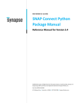
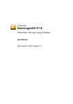
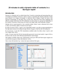
Figure
1
shows
the
terminal,
a
16x16
array,
to
the
PLATO
IV
computer
assisted
education
system,
released
in
1972,
which
is
one
of
the
first
touch
systems
to
be
generally
known.
Similar
systems
like
the
PLATO
IV
are
infact
used
today
in
cashpoints,
ticketing
machines,
medical
instrumentation
etc.
[1]
Figure
1:
The
Plato
IV
terminal
with
its
touch‐sensitive
screen
[1].
The
University
of
Toronto's
Input
Reasearch
Group
developed
the
first
human‐input
Multi‐touch
technology
that
dates
back
to
1982
(Macintosh
released
its
first
computer
in
1984)
and
the
now
so
common
and
well
known
pinch
gesture
(see
table
1,
in
section
5.1.2,
for
description)
dates
back
to
1983
[6].
This
first
system
was
not
like
todays
Multi‐touch
screens
where
you
click
on
the
actual
object,
but
a
pad
with
a
frosted
glass
that
had
a
camera
behind
it.
The
camera
detected
the
fingers
pressed
on
the
screen
as
black
dots
on
an
otherwise
white
background
[6].
The
system
was
also
said
to
be
somewhat
pressure
sensitive
since
the
size
of
the
dot
depended
on
how
hard
the
person
was
pressing
on
the
glass.
The
system
was
used
for
simple
image
processing
like
drawing
7
2. Theoretical background
etc.
Already
when
this
interface
was
created,
the
use
of
a
projector
together
with
a
camera
was
discussed,
much
like
a
lot
of
Multi‐touch
systems
use
today,
like
for
example
the
Microsoft
Surface
table‐top
touch
platform
(see
more
under
"Different
technologies").
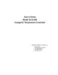
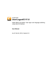
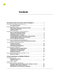
The
first
real
Multi‐touch
screen
was
developed
during
1984
by
Bell
Labs
and
the
first
system
to
use
capacitance
sensing
system
was
developed
during
1985
by
the
Input
Research
Group
at
the
University
of
Toronto
[6].
Figure
2:
The
first
multi‐touch
system
to
use
capitance
was
a
tablet
developed
at
the
University
of
Toronto
in
1985
[6].
Today,
many
Multi‐touch
manufacturer
use
some
kind
of
capacitance
system,
since
it
allows
a
slimmer
design
than
the
bulky
optical
system,
which
requires
projectors
and
sensors
(see
next
section),
and
because
it
eventually
allowed
a
transparent
capacitance
sensing
screen
to
be
placed
in
front
of
a
regular
LCD
or
LED
screen.
The
optical
system
is
still
widely
used
though
primarily
beacuse
it
is
a
lot
cheaper
and
easier
to
build
for
large
applicaton
where
space
is
not
limited.
2.3.2
Different
technologies
This
section
will
present
the
basics
for
the
two
most
common
Multi‐touch
technologies
of
today;
optical
sensing
systems
and
capacitance
sensing
systems.
Optical
sensing
systems
use
a
projection
of
the
screen
onto
a
surface
with
sensors
detecting
where
on
the
screen
you
are
touching.
A
capacitance
sensing
system
carry
an
electrical
charge
and
can
sense
where
on
the
screen
the
charge
gets
interupted
(like
the
Iphone)
[7].
The
technology
to
use
depends
mostly
on
the
size
of
the
screen
(also
how
much
space
that
is
available)
and
the
type
of
interface
the
application
shall
have.
The
principal
data
processing
though,
is
the
same
for
both
technologies.
The
input
signals,
created
by
fingers
or
other
objects
touching
the
screen,
gets
processed
by
a
software
that
recognizes
whether
it
is
a
just
a
touch,
multi‐touch
or
some
kind
of
gesture
and
then
translates
the
signals
and
excecutes
the
corresponding
commands.
8
2. Theoretical background
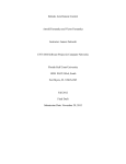
Touch
tables
and
touch
walls
are
examples
of
optical
sensing
systems
and
they
usually
use
projectors
that
sends
images
through
an
acrylic
or
glass
that
faces
the
viewer.
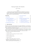
When
the
screen
is
touched
by
fingers
or
other
objects,
the
light
gets
scattered
and
the
reflection
is
sent
back
to
sensors
or
cameras
that
reads
the
change
and
send
it
to
the
software,
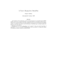
see
figure
3
and
4.
The
software
interprets
the
change
and,
depending
on
the
reading,
takes
the
appropriate
action
[8].
In
order
to
create
the
reflection,
LEDs
are
used
to
send
light
bouncing
through
the
acrylic
sheet
or
glass.
Figure
3:
Principal
function
of
a
touch
wall
[8].
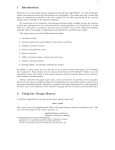
A
touch
table
works
in
a
similar
manner.
Figure
4:
When
a
Multi‐touch
system
using
optical
sensors
is
touched
by
a
finger
or
object
the
light
created
by
the
led
gets
scattered
and
sent
toward
a
reflection
sensor
[8].
9
2. Theoretical background
A
touch
sensitive
overlay
on
a
screen
and
a
built
in
touch
panel
are
examples
of
capacitance
sensing
systems.
The
main
technologies
are
mutual
capacitance
or
self‐capacitance
[9].
The
difference
is
that
the
mutual
capacitance
system
has
two
separate
layers
for
the
electrodes,
one
carrying
the
small
current,
and
the
other
is
the
sensing
circuit
that
measures
on
which
node
on
the
electrodes
that
the
current
gets
interrupted
by
a
touching
object.
The
self‐capacitance
system
on
the
other
hand,
has
electrodes
that
can
measure
the
capacitance
change
caused
by
an
object
directly.
[9]
2.4
Robot
Control
In
this
chapter
it
will
be
explained
the
common
practice
in
industrial
robot
control.
First
section,
programming,
explains
how
to
make
the
robot
perform
a
task
by
writing
a
robot
code
that
are
read
by
the
robot
controller
computer.
Further
down
in
the
section
"Programming
of
KUKA
robots"
it
will
be
explained
more
specific
about
how
the
controlling
is
done
with
KUKA
robots
and
how
the
robot
language
code
works.
Then
it
will
be
explained
more
about
what
type
of
controlling
method
that
was
used
in
this
project,
and
what
type
of
tools
that
were
used
for
that
under
the
sections
"Real‐time
control"
and
"KUKA
Ethernet
RSI
XML".
2.4.1
Conventional
control
The
common
practice
for
industrial
robot
control
is
either
to
move
the
robot
manually
with
the
robot’s
teach
pendent,
or
with
a
program
written
in
the
robot’s
language,
in
this
case
KUKA
Robot
Language
(KRL),
that
is
run
on
the
robot
controller.
Either
the
program
has
been
written
directly
in
the
specific
robot
language
or
the
programmer
has
used
some
kind
of
post
processor
in
combination
with
CAD/CAM
software.
The
programming
of
industrial
robot
can
be
divided
into
two
categories,
online‐,
and
offline
programming.
Offline
programming
means
that
the
robot
code
is
created
offline
with
no
connection
to
the
physical
robot.
The
generated
program
is
later
transferred
to
the
robot
and
executed
in
the
real
environment.
Normally
a
verification
of
the
code
is
made
in
some
sort
of
simulation
software
before
transferring
the
program.
Online
programming
includes
programming
when
the
software
is
directly
connected
to
the
physical
robot.
This
can
be
done
with
a
teach
pendant
(See
the
section
about
Industrial
robots)
used
for
moving
the
robot
to
certain
positions
where
they
are
stored,
and
then
a
trajectory
is
created
between
the
stored
points.
The
process
when
adjusting
a
position
in
space
is
commonly
referred
to
as
"jogging"
or
"inching"
the
robot.
Most
industrial
robots
have
a
similiar
programming
structure,
telling
them
how
to
act.
You
define
points
in
space
and
then
how
the
robot
is
supposed
to
reach
the
specific
points,
normally
called
P1,
P2,
P3
etc.
An
example
of
a
program
syntax
is
shown
below
in
figure
5.
10
2. Theoretical background
Move
to
P1
(a
general
safe
position)
Move
to
P2
(an
approach
to
P3)
Move
to
P3
(a
position
to
pick
the
object)
Close
gripper
Move
to
P4
(an
approach
to
P5)
Move
to
P5
(a
position
to
place
the
object)
Open
gripper
Move
to
P1
and
finish
Figure
5:
Example
of
short
robot
program
syntax.
Many
industrial
robot
manufacturers
offer
a
simulation
software
package
for
their
robots
which
eases
the
programming
and
at
the
same
time
makes
it
possible
to
perform
offline
programming.
The
benefits
from
using
offline
programming
are
many;
it
prevents
costly
damages
to
happen
in
the
real
world,
it
can
save
money
since
you
dont
have
to
interrupt
the
production
while
programming,
it
speeds
up
for
example
ramp‐up
time
when
switching
to
production
of
a
new
models
etc
[10].
2.4.2
Programming
of
KUKA
robots
(KRL)
For
programming
of
a
KUKA
robot,
a
specific
language
called
KRL
(KUKA
Robot
Language)
is
used.
The
structure
of
the
code
is
similar
to
most
other
robot
languages;
Points
are
specified
in
space
and
commands
are
used
to
express
how
the
robot
are
suppose
to
reach
these
points,
see
example
under
section
"General
programming".
When
programming
in
KRL,
a
.SRC‐file
is
created
containing
the
real
program
code
that
will
be
read
by
the
robot
controller
and
a
.DAT
file
containing
the
declaration
of
variables,
and
other
prerequisites
that
are
read
and
stated
automatically
before
executing
the
.SRC‐file.
The
name
of
the
two
files
shall
always
be
the
same
to
be
identified
as
the
same
program
by
the
robot
controller.
A
small
example
of
the
contents
in
a
.SRC‐file
is
shown
in
figure
6.
DEF
FR_VERS
(
)
;‐‐‐‐‐‐‐
Declaration
section
‐‐‐‐‐‐‐
EXT
BAS
(BAS_COMMAND
:IN,REAL
:IN
)
DECL
AXIS
HOME
;Variable
HOME
of
type
AXIS
;‐‐‐‐‐‐‐‐‐‐‐
Initialization
‐‐‐‐‐‐‐‐‐‐
BAS
(#INITMOV,0
)
;Initialization
of
velocities,
;accelerations,
$BASE,
$TOOL,
etc.
HOME={AXIS:
A1
0,A2
‐90,A3
90,A4
0,A5
0,A6
0}
;‐‐‐‐‐‐‐‐‐‐‐
Main
section
‐‐‐‐‐‐‐‐‐‐
PTP
HOME
;BCO
run
;
Motion
relative
to
the
$BASE
coordinate
system
PTP
{POS:
X
540,Y
630,Z
1500,A
0,B
90,C
0}
PTP
HOME
END
Figure
6:
An
example
of
KRL‐code
[11].
11
2. Theoretical background
The
declaration
and
initialization
part
can
also
be
located
in
the
.DAT
file,
but
are
here
showed
in
the
same
program
to
more
clearly
explain
the
different
steps.
The
PTP
HOME
in
the
main
section
makes
the
robot
perform
a
point‐to‐point
motion
to
the
defined
home
position,
which
is
defined
in
the
initialization
part.
The
first
instruction
to
the
robot
is
normally
called
a
BCO‐run
(Block
Coincidence),
which
makes
the
robot
go
to
a
predefined
point
in
space.
This
is
done
in
order
to
set
the
correspondence
between
the
current
real
robot
position
and
the
programmed
position.
The
next
line
makes
the
robot
go
to
the
specified
point,
which
in
this
case
is
defined
directly
in
the
same
row
as
a
point
in
the
base
coordinate
system
specified
by
six
values.
The
six
values
are;
X,
Y,
Z
that
defines
the
point
in
a
3D‐space
and
A
(rotation
around
Z‐axis),
B
(rotation
around
Y‐axis)
and
C
(rotation
around
X‐axis)
that
defines
the
tool
orientation
[11].
2.4.3
Realtime
control
Normally
industrial
robots
are
programmed
to
perform
a
single
task,
for
example
welding
the
same
part
over
and
over
throughout
the
day;
hence
it
is
not
controlled
in
real‐time.
However,
real‐time
control
can
be
used
for
tasks
that
are
none‐repeatable
and
require
the
user
to
alter
the
robot’s
movement
from
time
to
time.
Example
of
this
can
be
inspection
with
a
camera,
place
a
gripper
as
the
end‐effector
in
order
to
be
able
to
pick
up
and
move
different
objects
etc.
2.4.4
KUKA.Ethernet
RSI
XML
The
KUKA.Ethernet
RSI
XML
software
package
is
required
to
control
the
robot
externally
in
real
time.
The
term
external
system
is
often
mentioned
and
refers
to
the
computer(s)
that
are
connected
to
the
robot
controller
(in
this
case
the
computer
that
holds
the
server
that
the
robot
controller
is
communicating
with).
The
KUKA.Ethernet
RSI
XML
is
an
add‐on
technology
package
with
the
following
functions
[12]:
• Cyclical
data
transmission
from
the
robot
controller
to
an
external
system
in
the
interpolation
cycle
of
12ms
(e.g.
position
data,
axis
angles,
operating
mode,
etc.)
• Cyclical
data
transmission
from
an
external
system
to
the
robot
controller
in
the
interpolation
cycle
of
12ms
(e.g.
sensor
data)
• Influencing
the
robot
in
the
interpolation
cycle
of
12ms
• Direct
intervention
in
the
path
planning
of
the
robot
The
characteristics
of
the
package
are
the
following:
•
Reloadable
RSI‐object
for
communication
with
an
external
system,
in
conformity
with
KUKA.RobotSensorInterface
(RSI)
12
2. Theoretical background
•
Communications
module
with
access
to
standard
Ethernet
•
Freely
definable
inputs
and
outputs
of
the
communication
object
•
Data
exchange
timeout
monitoring
•
Expandable
data
frame
that
is
sent
to
the
external
system.
The
data
frame
consists
of
a
fixed
section
that
is
always
sent
and
a
freely
definable
section.
The
KUKA.Ethernet
RSI
XML
enables
the
robot
controller
to
communicate
with
the
external
system
via
a
real‐time‐capable
point‐to‐point
network
link.
The
exchanged
data
is
transmitted
via
the
Ethernet
TCP/IP
or
UDP/IP
protocol
as
XML
strings.
For
this
thesis
the
Ethernet
TCP/IP
was
used
since
it
makes
a
more
secure
communication
with
response
from
the
destination
to
the
host,
while
the
UDP/IP
lacks
this
response.
Programming
of
the
KUKA.Ethernet
RSI
XML
package
is
based
on
creating
and
linking
RSI‐
objects.
RSI‐objects
are
small
pieces
of
pre‐programmed
code
that
can
be
executed
and
has
additional
functionalities
than
the
normal
KRL‐code.
To
be
able
to
communicate
externally
through
Ethernet,
a
specific
standard
object
(ST_ETHERNET
or
ST_COROB)
needs
to
be
created.
The
code
line
for
creating
for
example
the
ST_ETHERNET
is
typically:
err=ST_ETHERNET
(A,B,config_file.xml)
Where,
err
is
a
type
of
string
used
by
the
RSI
XML
(called
RSIERR)
containing
the
error
code
produced
when
creating
the
object
(normally
#RSIOK
when
it
works),
A
is
an
integer
value
that
contains
the
specific
RSI‐object
ID
so
that
it
is
possible
to
locate
and
refer
to,
B
is
an
integer
value
for
the
container
to
which
you
want
the
RSI‐object
to
belong
in
order
to
create
a
group
of
different
objects
containing
to
the
same
container,
config_file.xml
is
a
configuration
file
located
in
the
INIT
folder
(path
C:/KRC/ROBOTER/INIT)
on
the
robot
controller
that
specifies
what
should
be
sent
and
received
by
the
robot
controller.
The
content
of
this
file
will
be
explained
further
down.
ST_ETHERNET
and
ST_COROB
are
objects
that
can
be
influenced
by
external
signals,
and
also
send
data
back
to
the
external
system
in
form
of
XML
files,
containing
different
tags
with
data.
The
data
can
be
for
example
information
about
the
robot’s
actual
axis
positions,
Cartesian
actual
positions
etc.
This
data
shall
sent
to
the
server
and
back
within
each
interpolation
cycle
of
12
ms.
ST_ETHERNET
has
the
same
functionality
as
ST_COROB
but
with
additional
functionalities;
one
of
these
object
always
need
to
be
created
and
correctly
linked
in
the
KRL
code
in
order
to
establish
communication
with
the
external
system.
In
this
project,
the
13
2. Theoretical background
communication
object
ST_ETHERNET
was
used.
When
one
of
these
objects
is
created
and
linked
correctly,
the
robot
controller
connects
to
the
external
system
as
a
client.
There
are
a
lot
of
different
types
of
RSI‐objects
and
depending
on
what
you
want
to
do,
you
have
to
create
and
link
the
correct
objects
to
each
other.
Besides
the
standard
Ethernet
card,
an
additional
card
(3COM)
was
needed,
to
be
able
to
handle
the
speed
of
the
transferred
data
[12].
Figure
7:
Functional
principle
of
data
exchange
[12].
The
robot
controller
initiates
the
cyclical
data
exchange
with
a
KRC
data
packet
and
transfers
further
KRC
data
packets
to
the
external
system
in
the
interpolation
cycle
of
12
ms.
This
communication
cycle
is
called
a
IPO‐cycle
(Input
Process
Output)
and
can
be
seen
in
figure
7
above.
The
external
system
must
respond
to
the
KRC
data
packets
with
a
data
packet
of
its
own.
14
2. Theoretical background
Figure
8:
Data
exchange
sequence
[12].
To
be
able
to
influence
the
robot,
one
needs
to
initiate
an
RSI‐object
for
the
movements.
There
are
mainly
two
objects
used
for
this.
First
an
object
called
ST_AXISCORR(A,B)
for
specific
movements
in
axis
A1
to
A6,
where
A
is
the
specific
ID
of
the
created
object,
and
B
is
the
container
that
the
object
belongs
to.
The
second
object
is
called
ST_PATHCORR(A,B)
for
movements
in
Cartesian
coordinates,
where
A,
B
are
the
same
as
for
the
ST_AXISCORR
object.
A
coordinate
system
is
also
needed
(normally
BASE,
TCP,
WORLD)
as
a
reference
for
the
movements.
This
is
done
by
creating
a
RSI‐object
called
ST_ON1(A,B)
where
the
parameter
A
is
a
string
containing
the
coordinate
system
that
is
supposed
to
be
used
(expressed
as
#BASE,
#TCP
or
#WORLD)
and
B
is
an
integer
value,
0
if
the
correction
values
sent
to
the
robot
shall
be
absolute
or
1
if
they
shall
be
relative.
A
schematic
picture
of
the
data
exchange
sequence
with
the
different
RSI‐objects
is
shown
in
figure
8
above.
When
the
robot
is
delivered
from
the
factory,
the
BASE
coordinate
system
is
the
same
as
the
WORLD
and
both
are
located
in
the
base
of
the
robot
by
default.
BASE
is
normally
moved
to
the
base
of
the
work
piece
on
which
the
robot
is
working.
The
differences
between
the
different
coordinate
systems
can
be
seen
in
figure
9
below.
NOTE:
For
the
robot
used
in
this
thesis,
all
three
systems;
WORLD
CS,
ROBOT
CS
and
BASE
CS
have
the
same
origin
located
on
the
base
of
the
robot.
15
2. Theoretical background
Figure
9:
The
different
coordinate
systems
[11].
Though
it
was
discovered
that
when
starting
the
WORLD
coordinate
system,
the
origin
where
set
on
where
the
robot
were
standing
when
starting
the
system.
This
only
applies
for
the
communication
to
the
robot
controller,
so
that
the
starting
position
shall
always
be
set
as
0
before
starting
to
move
the
robot.
The
response
sent
back
to
the
external
system
was
in
real
coordinates
with
the
WORLD
coordinate
system
starting
at
its
standard
position
on
the
base
of
the
robot.
When
the
robot
controller
communicates
with
the
external
system
it
interchanges
XML
Strings.
The
content
in
the
XML
strings
for
the
demo
program
provided
by
KUKA,
is
decided
and
defined
in
a
file
called
ERX_config.xml
(the
configuration
file,
mentioned
above),
which
is
located
in
the
robot
controller,
inside
the
INIT
folder.
A
typical
example
of
the
content
in
this
file
is
shown
in
figure
10
below.
16
2. Theoretical background
<ROOT>
<CONFIG>
<IP_NUMBER>192.0.1.2</IP_NUMBER>
<PORT>6008</PORT>
<PROTOCOL>TCP</PROTOCOL>
<SENTYPE>ImFree</SENTYPE>
<PROTCOLLENGTH>Off</PROTCOLLENGTH>
<ONLYSEND>FALSE</ONLYSEND>
</CONFIG>
<SEND>
<ELEMENTS>
<ELEMENT
TAG="DEF_RIst"
TYPE="DOUBLE"
INDX="INTERNAL"
UNIT="0"
/>
<ELEMENT
TAG="DEF_RSol"
TYPE="DOUBLE"
INDX="INTERNAL"
UNIT="0"
/>
<ELEMENT
TAG="DEF_AIPos"
TYPE="DOUBLE"
INDX="INTERNAL"
UNIT="0"
/>
<ELEMENT
TAG="DEF_ASPos"
TYPE="DOUBLE"
INDX="INTERNAL"
UNIT="0"
/>
</ELEMENTS>
</SEND>
<RECEIVE>
<ELEMENTS>
<ELEMENT
TAG="DEF_EStr"
TYPE="STRING"
INDX="INTERNAL"
UNIT="0"
/>
<ELEMENT
TAG="RKorr.X"
TYPE="DOUBLE"
INDX="1"
UNIT="1"
HOLDON="1"
/>
<ELEMENT
TAG="RKorr.Y"
TYPE="DOUBLE"
INDX="2"
UNIT="1"
HOLDON="1"
/>
<ELEMENT
TAG="RKorr.Z"
TYPE="DOUBLE"
INDX="3"
UNIT="1"
HOLDON="1"
/>
<ELEMENT
TAG="RKorr.A"
TYPE="DOUBLE"
INDX="4"
UNIT="0"
HOLDON="1"
/>
<ELEMENT
TAG="RKorr.B"
TYPE="DOUBLE"
INDX="5"
UNIT="0"
HOLDON="1"
/>
<ELEMENT
TAG="RKorr.C"
TYPE="DOUBLE"
INDX="6"
UNIT="0"
HOLDON="1"
/>
</ELEMENTS>
</RECEIVE>
</ROOT>
Figure
10:
The
structure
of
ERXconfig.xml.
As
can
be
seen
in
figure
10
above,
the
IP
address
and
port
to
which
the
robot
controller
will
connect,
when
establishing
the
connection,
are
set
in
this
file.
The
sub
tags
under
<SEND>
are
what
the
robot
controller
sends
to
the
external
system.
The
most
important
tags
for
sending
to
the
external
system
for
this
project
are
the
tags
called
DEF_RIst,
which
is
the
real
position
of
the
robot’s
end‐effector,
and
DEF_RSol
that
is
the
set
position
received
from
the
external
system.
The
DEF_AIPos
and
DEF_ASPos
are
real
axis
position
and
set
axis
position
respectively.
Under
the
tag
RECEIVE
is
described
what
the
robot
controller
expects
to
receive
from
the
external
system.
In
this
case
only
corrections
in
six
values
(X,
Y,
Z,
A,
B
and
C)
are
included,
tagged
as
RKorr.
The
meanings
of
these
six
values
are
described
above
under
the
section
"programming
of
KUKA
robots".
17
3. Hardware and software prerequisites
3.
Hardware
and
software
prerequisites
3.1
Robot
The
robot
used
in
this
project
is
a
KUKA
KR
5
sixx
R650
together
with
a
KUKA
KR
C2
sr
controller.
This
compact
robot
is
a
light‐weight,
fast
and
reliable
robot
for
its
size.
Since
this
robot
is
able
to
be
mounted
on
the
ceiling
it
was
beneficial
for
our
project.
A
ceiling
mounted
robot
is
suitable
for
inspection
purposes
since
you
can
get
the
best
overview
and
can
also
go
around
objects
in
an
easier
way
without
touching
them.
Robot specifications
(Source:
KUKA
webpage,
www.Kuka.com):
Model:
KR
5
sixx
R650
Payload:
5kg
Max.
reach:
650mm
Speed:
375
°
/s
Controller:
KR
C2sr
Number
of
axes:
6
Repeatability:
<±0,02
mm
Weight:
28
kg
Mounting
positions:
Floor,
ceiling
Speed
max.:
8,2
m/s
Figure
11:
KUKA
KR
5
sixx
R650
robot
with
its
specifications
[13].
3.2
Robot
controller
The
robot
controller
used
in
this
project
is
a
KR
C2
sr
controller.
The
KR
C2
sr
uses
an
embedded
version
of
Windows
XP
as
operating
system.
This
means
that
the
operating
system
is
a
special
version
of
Windows
XP
built
to
be
run
in
parallel
with
KUKA's
own
controller
application.
3.2
Screen
The
Multi‐touch
screen
used
in
this
thesis
is
a
Multi‐touch
overlay
for
a
42‐inch
monitor,
called
G3
Basic
(Figure
12).
The
overlay
is
produced
by
a
company
called
PQ
Labs
situated
in
Silicon
Valley,
USA.
The
company
is
a
provider
of
Multi‐touch
solutions,
developing
both
hardware
and
software
in
the
field
of
broadcast,
digital
signage,
defense,
geo‐intelligence,
product
presentation
and
interactive
education
etc.:
18
3. Hardware and software prerequisites
Specifications:
•
•
•
•
•
•
6
touch
points
42"
screen
size
3mm
tempered
glass
No
touch
activation
force
required
7‐12ms
touch
response
time
Powered
by
USB
Figure
12:
PQ
Labs
G3
Multi‐touch
overlay
and
LG
42”
full
HD
screen
[14].
3.3
External
computers
Since
the
applications
that
were
run
in
this
project
need
a
lot
of
resources
to
work
the
way
it
is
intended,
computers
with
a
relatively
high
performance
with
today's
standards
were
necessary.
The
whole
system
consists
of
three
computers
(including
the
robot
controller
computer);
one
running
the
interface,
one
running
the
server
and
the
last
one
is
the
robot
controller.
The
computer
running
the
server
(see
explanation
under
system
development)
was
a
quad
processor
(4
cores)
of
2,73GHz
with
4GB
RAM.
This
computer
was
needed
since
almost
all
CPU
could
be
dedicated
only
for
the
communication
(response
to
the
controller
was
needed
every
12
ms)
which
we
found
to
be
stable
with
this
solution.
The
computer
running
the
interface
also
needed
to
perform
well
since
a
smooth
communication
with
the
server
was
desired.
For
this
purpose
a
computer
with
a
dual
core
processor
of
2,7GHz,
and
4
GB
of
RAM
was
used.
3.4
Software
In
this
project
a
lot
of
different
softwares
have
been
used.
Since
the
focus
of
this
Master
thesis
is
on
the
robot
communication,
only
a
short
description
will
be
presented
of
what
softwares
that
were
used
for
programming
the
interface.
The
first
version
of
the
interface
was
programmed
in
Flash
with
ActionScript3
(AS3)
built
in
Adobe
flex
4
together
with
Unity
3D.
The
second
version
was
built
using
Windows
Presentation
Foundation
(WPF),
specifically
Microsoft
Visual
Studio
2010,
running
on
windows
7.
The
language
used
for
second
version
was
XAML
for
UI
components
and
C‐sharp
for
the
logic.
The
reason
why
it
was
transferred
to
C‐sharp
was
that
the
new
Visual
Studio
with
built‐in
support
for
Multi‐touch
interfaces
came
out
during
the
work
with
the
project.
19
4 Methodology
4
Methodology
In
this
section
the
experimental
methodology
that
was
used
during
the
project
is
described.
The
methodology
is
divided
into
the
parts
Initiation,
Setup,
Establishment
of
communication,
Interface
design
and
Concept
evaluation.
4.1
Initiation
A
comprehensive
literature
study
was
initially
carried
out
in
order
to
document
the
different
domains
of
shared
control,
human‐machine
interface
and
real‐time
control.
In
this
study
basic
knowledge
in
the
following
was
also
included:
•
•
•
How
to
program
the
Multi‐touch
screen
using
Adobe
Flash
Builder
(for
the
visual
touch
controls
and
video
feeds)
and
Microsoft
Visual
Studio
2010
in
combination.
The
specific
robot
used
in
the
project,
namely
a
KUKA
KR
5
sixx
R650
robot.
Ways
to
remotely
control
the
robot
with
an
external
device
using
direct
connection
through
serial
port,
Ethernet,
OPC
(OLE
for
Process
Control)
etc.
4.2
Setup
A
demonstrator
was
developed
in
order
to
illustrate
and
study
some
vital
functions
of
the
system
setup.
The
safety
solution
was
limited
in
the
demonstrator,
which
means
that
extra
arrangements
for
personal
and
machine
safety
were
integrated
so
that
all
necessary
precautions
were
taken
when
operating
the
demonstrator
robot.
The
two
different
areas
of
the
project
was
commenced
in
parallel
and
will
from
here
on
be
referred
to
as
"Interface"
and
"Robot
control"
respectively.
These
two
parts
of
the
project
were
later
coupled
together.
4.3
Establishment
of
communication
To
establish
the
communication
some
different
options
were
studied.
There
were
for
example
communication
via
a
OPC‐server,
communication
via
serial
port
and
ethernet
communication
via
XML‐strings.
Since
this
project's
objective
was
to
control
the
robot
in
real
time,
a
fast
and
responsive
way
of
communication
was
needed.
The
fastest
way
of
communicating
was
the
ethernet
communication
with
XML‐strings
that
had
a
communication
interpolation
cycle
of
12
ms,
which
should
be
more
than
enough
for
this
project.
To
get
this
to
work,
the
KUKA
RSI
XML
1.2
(described
above
in
the
section
“Theoretical
background”)
was
used.
Also
an
extra
ethernet
card
allowing
high
speed
data
interaction
was
needed
in
the
controller
computer
to
be
able
to
establish
the
communication.
In
the
case
of
this
thesis,
at
first
a
demo
program
developed
by
KUKA
was
run
on
the
robot
controller,
together
with
KUKA:s
demo
server
in
order
to
establish
and
test
the
communication
with
an
external
system.
20
4 Methodology
4.4
Interface
design
When
designing
the
interface,
data
based
on
how
people
act
is
needed
to
be
able
to
make
it
as
user
friendly
and
intuitive
as
poossible.
In
this
project
a
study
of
the
documentation
of
previous
human
experiments
with
Multi‐touch
screens
was
made
in
order
to
collect
as
much
knowledge
as
possible.
Then
this
knowledge
was
applied
in
the
interface
design
and
common
commands
and
gestures
were
used
for
controlling
the
different
objects.
For
example
the
study
revealed
that
the
two‐finger
spread
motion
to
zoom
and
the
single
finger
drag
for
panning
had
been
proved
to
be
very
intuitive
in
previous
studies.
A
sketch
of
how
the
interface
were
supposed
to
look
like
when
finished
was
made
after
meetings
and
discussions
of
what
could
be
the
best
way
of
designing
the
interface.
It
was
not
necessary
to
follow
paradigm
on
how
a
UI
should
be
designed,
so
new
inventions
were
also
discussed.
4.5
Concept
evaluation
The
method
used
to
evaluate
the
developed
concept
and
the
built
demonstrator
has
been
to
perform
usability
tests.
User
tests
were
chosen
as
evaluation
method
because
it
gives
a
good
picture
of
the
intuitivism
of
the
screen
from
the
users
point
of
view.
After
the
tests
were
performed
the
results
were
collected,
analyzed
and
conclusions
were
drawn,
see
"conclusion"
section".
21
5. System development process
5.
System
development
process
The
project
is
divided
into
3
main
parts:
•
•
•
Interface
Development
Robot
Controller
Programming
(KRL)
Communication
These
parts
will
be
explained
under
the
following
sub‐sections.
5.1
Interface
Development
This
project
has
aimed
to
get
the
user
interface
(UI)
as
intuitive
as
possible.
A
lot
of
research
has
been
done
about
previous
experiments
and
knowledge
achieved
from
those,
to
see
which
design
could
be
most
suitable
for
this
specific
project.
Mostly
the
research
was
focused
on
shared
control
and
design
of
human‐machine
interfaces
(HMI).
The
appearence
of
the
interface
and
the
function
was
discussed
and
evaluated
before
deciding
the
final
concept
of
UI
to
use.
Through
discussion,
with
the
members
of
the
group
who
were
responsible
for
the
programming
of
the
Multi‐touch
screen,
different
possibilities
of
how
to
design
the
first
beta‐version
of
the
interface
were
investigated.
It
was
agreed
initially
that
the
most
important
part
of
the
project
was
not
to
find
the
absolute
best
way
to
design
the
interface,
but
rather
see
what
was
possible
to
do
and
whether
it
was
possible
to
establish
a
good
communication.
The
development
of
the
interface
layout
when
it
comes
to
intuitivism
and
user
friendliness
was
initially
of
second
nature,
depending
on
success
of
the
communication
part
of
the
project.
What
was
of
greater
importance
however,
was
what
sort
of
data
packages
that
had
to
be
sent
to
the
controller
and
via
which
ports.
The
first
step
in
building
of
the
interface
was
to
be
able
to
move
the
robot
in
the
X‐Y‐plane
with
a
simple
2D
interface,
see
figure
13.
When
that
was
solved,
the
project
moved
on
to
developing
the
interface
further
and
implementing
control
of
the
other
robot
movements,
such
as
the
Z‐
direction,
tool
orientation
and
individual
rotation
of
the
robots
A1‐joint
(First
joint
counting
from
the
base
of
the
robot).
This
programming
was
done
in
flash
language
using
flash
builder
at
a
mini‐MAC
that
was
connected
to
the
Multi‐touch
screen.
22
5. System development process
Figure
13:
XY
and
Z
controls
in
the
first
version
of
the
interface.
Then
a
conceptual
sketch
showing
how
the
layout
of
the
interface
was
created.
This
can
be
seen
in
figure
14.
This
concept
was
never
fully
tested
since
the
recording
area
was
left
for
later
implementation.
Log
console
3d Simulation
Views
Video Feeds
Setup - Recording Area
Tool Control
Orientation Control
XYZ Controls
Figure
14:
Conceptual
sketch
of
the
first
version
of
the
interface
that
never
was
created.
23
5. System development process
Figure
15:
Photo
of
the
first
version
of
the
interface.
One
important
thing
when
designing
the
UI
was
how
to
interpret
the
tool
orientation.
Two
different
concepts
or
a
combination
of
the
two
were
considered
for
the
solution
of
the
tool
orientation
control.
The
first
concept
was
a
ball,
which
could
be
rotated
in
all
three
axes
simultaneously
using
one
finger
touch
and
movements;
this
can
be
seen
in
figure
15
above.
The
second
was
a
ball,
which
could
be
rotated
in
only
two
directions
(B
and
C)
with
one‐finger
touch.
For
the
second
concept,
the
rotation
of
A
(around
the
Z‐axis)
was
done
by
a
different
module
other
than
the
ball.
The
theory
behind
this
solution
is
that
the
user
might
find
it
more
intuitive
and
easier
to
control
the
A
rotation
separately
since
controlling
all
three
rotations
with
the
same
module
might
be
considered
as
to
complex.
Early
tests
with
the
first
concept
proved
that
it
was
hard
to
move
the
first
ball
back
to
its
original
position
after
moving
it
around
for
a
bit,
something
that
was
easier
with
the
second
concept.
On
the
other
hand
the
second
concept
needed
two
modules
and
the
first
only
one,
which
might
seem
to
add
a
bit
more
complexity
to
the
interface.
These
two
concepts
or
rather
a
combination
of
the
two
was
then
decided
to
use
as
the
final
version
of
the
tool
orientation,
which
is
described
further
down
in
this
section.
The
HMI
that
was
created
in
this
project
has
the
aim
to
move
a
robot
in
a
3D‐space
from
a
2D‐
interface.
The
problem
was
to
get
it
as
intuitive
as
possible
with
controllers
and
commands
from
the
2D‐space
that
should
be
transferred
into
3D‐motions.
In
other
words,
movements
in
the
3rd
direction
must
be
substituted
by
some
kind
of
motion
or
gesture
that
is
easy
to
understand
and
as
self‐explanatory
as
possible.
24
5. System development process
After
testing
the
interface
built
in
Flash,
figure
15,
it
was
realized
that
after
some
use
it
started
lagging
and
was
not
as
smooth
as
wanted.
Therefore
experiments
were
made
on
controls
made
in
Visual
Studio
2010
in
programming
language
C#,
and
it
seemed
to
be
smoother
for
this
kind
of
purpose.
Hence
a
translation
of
the
code
from
flash
to
C#
was
made.
Also
experiments
were
made
with
other
layout
of
the
controls
since
it
was
discovered
by
tests
that
the
controls
could
be
improved
from
the
first
version.
The
first
conceptual
sketch
of
the
second
version
of
the
interface
can
be
seen
in
figure
16
and
figure
17
below:
Log/Connection / Setup/
Recording Area
3D Visualization
Of
Robot
Information
Angles
A1 A2 A3 A4 A5
A6
ALERTS
Camera on robot
Position
Control
(Global XYZ)
Orientation
Control
(Global
ABC)
Figure
16:
Conceptual
sketch
of
the
second
version
of
the
interface.
Figure
17:
Photo
of
the
second
version
of
the
interface.
25
5. System development process
After
more
discussion
and
testing,
the
final
version
of
the
interface
for
this
project
was
decided
and
a
conceptual
sketch
from
the
interface
is
shown
in
figure
18
below:
Connect/disconnect
buttons
3d Simulation
Log X,Y,Z,A,B,C
real values
CAMERA ON ROBOT
+
Local coor. control
XYZ+BC
Orientation
Control
(Global
ABC)
Position
Control
(Global XYZ)
Figure
18:
Conceptual
sketch
of
the
third
and
final
version
of
the
interface.
As
can
be
seen,
the
ability
to
move
the
robot
in
the
A1
axis
separately
was
never
used.
This
was
due
to
the
fact
that
the
meaning
was
to
get
it
as
simple
as
possible,
especially
for
the
user
tests.
A
screenshot
is
shown
in
figure
19
below:
Figure
19:
The
third
and
final
version
of
the
interface.
26
5. System development process
The
interface
now
consists
of
one
area
for
movements
in
XY,
one
slider
for
movements
in
Z,
one
“video
control”
for
movements
in
local
coordinates,
one
ball
for
orientation
of
the
tool
maintaining
the
same
point
in
space
and
a
graphical
visualization
of
the
robot
position
based
on
the
real
feedback
from
the
robot.
Besides
that,
an
area
with
the
real
values
of
X,
Y,
Z,
A,
B
and
C
are
shown
in
the
middle
of
the
screen,
and
connect/disconnect
buttons
in
the
upper
left
corner.
The
controlling
with
respect
to
the
local
coordinate
system
is
placed
as
an
overlay
control
over
a
video
stream
coming
from
the
camera
mounted
on
the
tool
tip.
The
idea
was
that
controlling
it
in
this
way
should
be
intuitive
since
it
can
directly
be
seen
what
is
being
controlled.
To
control
the
camera
locally
in
the
plane,
one
finger
is
used
to
“snap”
the
background
and
then
dragging
to
move
it
in
the
desired
direction.
To
go
forward
and
backward
(direction
of
the
lens)
a
pinch
motion
is
used
(see
section
“proposed
gestures”).
At
the
end
it
was
decided
that
all
movements
on
the
interface
should
be
translated
into
X,
Y,
Z
and
A,
B
and
C
coordinates
respectively.
Therefore
to
do
the
movements
in
local
coordinates,
these
are
translated
into
the
global
coordinates
before
sending
them
to
the
robot.
This
is
done
by
checking
the
orientation
of
the
camera
and
then
calculating
the
projection
in
each
axis,
before
sending
the
target
coordinates.
As
mentioned
above,
to
control
something
in
3D‐
from
a
2D‐interface
is
complex,
so
one
direction
needs
to
be
interpreted
and
translated
to
a
motion
in
some
way.
To
be
more
self‐
explanatory,
a
redesigning
of
the
3D‐ball
(orientation
of
the
camera)
was
done.
At
the
beginning
it
was
just
a
3D‐ball
controlled
by
one
finger
in
all
directions.
When
tested
it
was
realized
that
it
must
be
better
to
have
one
finger
controlling
rotation
around
X
and
Y
(B
and
C
respectively)
so
that
the
ball
can
“snap”
to
the
finger
that
is
touching.
This
results
in
a
more
precise
controlling
of
the
orientation.
The
last
direction
A
(rotation
around
Z)
is
then
separated
and
controlled
by
a
two‐finger
rotation
on
the
same
controller.
In
previous
tests
[15]
most
users
chose
two
fingers
for
rotation.
For
an
explanation
of
all
gestures
used
in
this
project,
see
section
“Proposed
gestures”
further
down.
The
intention
has
been
to
make
the
controls
that
are
natural
for
the
user.
The
grid
control
includes
both
the
XY‐control
and
the
Z‐control,
and
work
in
the
same
manner.
When
touching
the
blue
ball
with
one
finger
and
moving
it,
it
snaps
to
the
finger
and
the
robot
follows
your
finger.
The
white
dot
in
the
center
of
the
blue
ball
is
the
real
position
of
the
robot
so
when
moving
it,
one
can
directly
see
the
latency
of
the
commands
according
to
the
robot’s
actual
position.
The
final
step
to
evaluate
the
interface
was
to
perform
a
usability
test
of
the
interface
with
a
small
test
group
containing
people
with
different
backgrounds,
age
and
sex,
see
section
”Usability
tests”.
27
5. System development process
5.1.1
Layout
Main
components
with
pictures
from
the
first
version
of
the
UI
are
described
here
Main visualization area
3D Simulation views
Video feeds from a webcam located close to the robot.
Main control area.
Multi-touch controls compiled with Flex
Y/XZ Position, Orientation and Tool Controls
Log console. A simple white space to show log-data.
Show the data sent and received
Figure
20:
Different
areas
on
the
Multi
touch
screen’s
interface.
28
5. System development process
5.1.2
Proposed
gestures
Gestures
do
not
have
a
global
meaning;
each
Multi‐touch
device
(like
the
Iphone)
associates
different
gestures
to
fixed
actions,
simple
or
complex
ones.
In
most
cases
the
same
gesture
is
reused
in
different
contexts
to
perform
specific
functions,
which
also
has
been
done
in
this
project.
(Otherwise
many
different
gestures
are
needed,
which
make
it
complex
and
hard
to
remember)
Table
1
shows
a
list
of
gestures
and
the
contextual
meaning
on
the
UI.
Table
1:
Proposed
gestures
for
robot
control.
Gesture
Graphics
DRAG
Context
Control
Area
Position
Handlers:
xy
+
z
Meaning
Move
XY
and/or
Z
positions
of
the
end‐
effector
(1
or
2
hands)
Control
Area
Grid
Move
the
Grid
to
reframe
the
Control
Area
Gesture
ROTATE
Graphics
Orientation
Control
Move
TrackBall
to
Area
Orientate
the
end‐
Rotation
Handler
(B+C)
effector.
Simulation
View
Area
Orbit
(Tilt/roll)
3D
Perspective
Camera
around
the
targeted
robot
on
the
3d
view.
Setup
Area
Buttons
Switch
on/off
safe
Buttons
slider
buttons.
(Not
implemented
in
the
demonstrator)
Context
Orientation
Control
Area
Rotation
Handler
(A)
29
Meaning
Rotate
the
tool
of
the
robot
arm.
(1
or
2
hands)
5. System development process
Gesture
PINCH
SCALE
ZOOM
Graphics
Context
Position
Control
Area
Position
Grid
Position
Control
Area
Tool
Handler
Meaning
Zoom
in/out
the
Grid
to
change
the
scale
of
the
coordinates
system
on
the
Control
Area
and
the
3d
views.
(1
or
2
hands)
Open/close
the
tool
if
it
is
a
claw
5.2
Robot
Controller
Programming
The
different
ways
of
controlling
the
robot
in
real
time
were
investigated
(since
this
is
not
a
common
practice
for
controlling
an
industrial
robot)
in
parallel
with
research
about
Multi‐touch
screens
and
research
in
the
different
domains
of
shared
control,
human‐machine
interface
and
real‐time
control.
In
order
to
establish
the
communication
via
Ethernet,
the
add‐on
software
package
called
KUKA
Ethernet
RSI
XML
1.2
(described
above
in
the
section
“Theoretical
background”)
was
required.
Hence,
this
software
together
with
latest
KUKA
robot
simulator
software,
SimPro
v.2.1,
and
KUKA’s
virtual
controller,
OfficeLite
v.5.4,
was
ordered
from
KUKA.
When
SimPro
and
OfficeLite
are
run
in
parallel
this
can
be
used
as
a
virtual
setup
of
the
real
robot
and
its
controller.
The
purpose
is
that
it
should
work
and
behave
as
similar
as
possible
to
the
reality.
SimPro
was
used
in
the
early
stages
of
the
project
in
order
to
test
the
functionality
of
the
Ethernet
RSI.XML
in
a
virtual
environment
first,
in
order
to
learn
how
to
use
it
before
commencing
the
testing
with
the
real
robot.
The
Ethernet
RSI
XML
package
came
together
with
demo
programs
from
KUKA
as
example
of
how
the
package
could
be
used.
While
waiting
for
the
software
packages
to
arrive,
the
documentation
of
the
software
was
studied.
In
order
to
get
everything
to
work,
licenses
needed
to
be
ordered
separately
after
receiving
the
software.
When
that
was
done,
experiments
started
on
how
to
control
the
robot
real‐time
in
the
virtual
world.
This
was
done
by
first
installing
all
software
on
the
same
computer,
then
importing
a
virtual
model
of
the
robot
in
SimPro
and
then
trying
to
connect
SimPro
with
the
virtual
controller
in
OfficeLite.
When
that
connection
was
stable,
it
was
possible
to
move
the
robot
manually
through
the
virtual
teach
pendant
in
OfficeLite.
Then
the
sample
program
for
KUKA
Ethernet
RSI
XML
was
run,
together
with
the
sample
server
provided
in
the
Ethernet
RSI
XML
package.
At
first
a
lot
of
problems
were
experienced,
such
as
unstable
communication,
problems
with
moving
the
robot
in
all
directions,
problems
with
exceeding
allowed
speeds
in
30
5. System development process
the
joints
that
caused
the
robot
communication
to
break
etc.
All
these
problems
and
the
causes
are
explained
in
table
2
below.
Table
2:
Encountered
problems
that
caused
the
communication
to
break.
Problems
• Speed
exceeded
in
several
joints,
especially
joint
A4
Solutions
• Changing
the
system
variable
$CP_VEL,
from
#CONSTANT
to
#VAR_ALL
•
Too
high
forces
on
robot
axis.
•
Changing
the
system
variable
$CP_VEL,
from
#CONSTANT
to
#VAR_ALL
•
Work
envelope
exceeded
•
Limit
the
workspace
by
using
RSI‐
object
ST_SETPARAM
•
Software
limit
switch
reached,
all
joints
•
Limit
the
workspace
by
using
RSI‐
object
ST_SETPARAM
Set
a
new
starting
position,
that
are
outside
risk
of
singularity
•
•
Communication
randomly
was
interrupted
•
Moving
the
server
to
a
more
powerful
computer,
able
to
response
within
the
IPO
cycle
of
12ms
Once
the
programming
of
the
demo
programs
was
understood
and
a
stable
communication
with
the
virtual
robot
was
established,
the
project
moved
on
to
trying
to
control
the
real
robot.
As
mentioned
before
the
real
robot
required
a
special
3COM
card
to
be
installed
on
the
controller
computer
in
order
to
connect
via
Ethernet
to
an
external
computer.
This
was
not
required
on
the
computer
running
the
virtual
controller
and
the
simulator
since
it
had
the
same
IP
address
and
communicated
internally.
So
this
had
to
be
ordered
as
well
and
was
later
installed
by
a
technician
from
KUKA.
The
reason
why
it
was
not
sent
from
the
beginning
was
that
this
technology
is
so
new
that
very
little
information
on
how
to
use
it
was
to
be
found
and
the
person
that
received
the
order
of
the
XML
package
at
KUKA
was
not
aware
of
that
it
was
needed.
Once
the
card
was
installed
and
tested
together
with
the
RSI
XML
demo
program
and
the
sample
server
provided
by
KUKA,
the
connection
could
finally
be
established.
A
MATLAB
toolbox
was
also
studied
for
inverse
kinematics
to
use
for
a
3D
simulation
of
the
robot.
Inverse
kinematics
can
be
simplified
as:
given
the
real
position
of
the
end‐effector,
it
calculates
the
joint
angles
that
are
needed
to
reach
this
point.
It
was
later
realized
that
this
was
not
required,
since
full
feedback
is
received
from
the
robot
in
form
of
all
angles
and
real
31
5. System development process
positions
of
each
joint,
according
to
the
coordinate
system
that
is
used
for
reference
(in
this
case
WORLD
coordinate
system).
During
the
first
tests,
KUKA’s
own
demo‐server
was
used
for
communication
with
the
robot
controller.
It
was
almost
directly
discovered
that
joint
A4
in
the
robot
had
too
much
speed
in
many
movements,
so
that
software
switches
built‐in
in
the
robot
controller
interrupted
the
robot
communication.
In
order
to
get
the
real
time
control
to
work
with
KUKA’s
own
server
in
a
satisfying
way,
the
values
of
an
RSI‐object
called
SETPARAM
needed
to
be
altered
to
prevent
the
software
limit
switches
to
be
activated
and
hence
stop
the
communication.
SETPARAM
sets
the
upper
and
lower
limits
of
each
moving
axis
and
rotation
angles,
hence
creating
the
work
envelope.
The
work
envelope
is
the
area
where
the
robot
is
allowed
to
move
within.
The
communication
remains
stable
even
if
these
limits
are
reached
and
only
causes
the
robot
to
stand
still,
until
a
value
within
the
set
limits
are
received.
Worth
noticing
is
that
to
be
able
to
not
exceed
any
limits
of
the
orientation
of
the
tool,
the
A,
B
and
C
values
needed
to
be
set
to
20
degrees
of
movement
in
all
directions.
The
limits
set
for
X,
Y
and
Z
were
‐130
–
130,
‐130
–
130,
‐
25
–
20
in
mm
respectively.
The
speed
of
the
A4
joint
were
also
exceeded
at
various
occasions
and
that
was
eventually
solved
by
changing
a
system
parameter,
$CP_VEL,
from
#CONSTANT
to
#VAR_ALL.
The
effect
of
this
is
that
when
the
robot
controller
receives
a
command
that
will
cause
any
of
the
axes
to
move
too
fast,
it
will
slow
down
the
movement
to
avoid
any
movement
that
will
cause
interruption
(failure).
The
software
limit
switches
are
only
preset
limits
set
to
avoid
any
hardware
damages.
When
starting
the
coordinate
system
with
the
parameter
ST1_ON
(A,B),
one
can
also
decide
if
the
values
received
by
the
robot
controller
should
be
incremental
from
the
start
position
or
absolute
values,
also
referring
to
the
start
position
of
the
robot.
After
discussing
with
the
other
group
members
it
was
decided
to
use
the
base
coordinate
with
absolute
values
instead
of
incremental
values,
since
the
staring
position
always
remains
the
origin
for
the
movements.
When
using
the
interface
it
was
realized
that
the
robot
would
have
much
larger
work
envelope
if
the
single
joints
could
be
moved
separately.
First
this
was
implemented
for
Joint
A1,
since
this
would
make
the
whole
robot
turn.
After
testing
the
demonstrator,
it
was
realized
that
when
moving
this
joint,
the
whole
coordinate
system
moves
in
accordance
with
the
movements
in
A1.
The
control
for
the
A1‐joint
was
disabled
during
the
usability
tests
due
to
that
the
fact
that
it
would
have
been
one
more
control
for
the
users
to
learn.
The
goal
was
to
perform
the
test
with
a
simple
but
still
fully
working
interface.
In
order
to
make
the
tool
orientation
rotate
around
the
lens
of
the
PS3‐camera,
mounted
on
the
tool
tip
of
the
robot,
the
Tool
Center
Point
(TCP)
had
to
be
moved.
The
TCP
has
its
own
coordinate
system
and
by
default
the
origin
is
located
at
the
tip
of
the
robot,
shown
in
figure
21
below.
This
transformation
of
the
TCP,
were
made
directly
in
the
program
by
first
measuring
the
real
displacement
of
the
PS3‐camera
lens
from
the
default
origin
(compare
Tool
CS
in
figure
9
and
figure
21).
The
coordinates
of
the
lens
were
then
introduced
in
the
KRL
code
of
the
robot
controller.
32
5. System development process
Figure
21:
Default
Tool
CS
[11].
When
running
the
robot
using
the
Multi‐touch
screen,
it
was
discovered
that
sometimes
the
robot
made
a
very
fast
rotation
of
the
A4‐joint
and
sometimes
tried
to
rotate
the
A4‐joint
too
much
(thus
triggering
the
software
limit
switches),
causing
the
communication
to
break.
This
phenomena
is
caused
by
something
that
is
called
singularity.
Singularity
occurs
when
two
of
the
robot's
axis
are
lined
up,
causing
the
robot
to
have
an
infinite
number
of
possible
solutions
to
reach
the
target
position.
For
example,
if
axis
4
and
6
are
lined
up,
see
figure
22,
and
the
robot's
target
position
requires
a
roll
of
20
degrees,
the
robot
could
use
an
infinite
number
of
combinations
to
satisfy
that
roll
value:
(30
deg,
‐10
deg),
(50
deg,
‐30
deg),
(0
deg,
20
deg)
etc.
This
results
in
high
speeds
and
unpredictable
movements
of
the
axes
in
between.
The
singularity
problem
was
solved
by
changing
the
system
variable
$CP_VEL,
from
#CONSTANT
to
#VAR_ALL
(limits
the
speed
by
slow
down
the
end‐effector
movement
in
order
to
not
exceed
any
axis
angle
velocity),
and
by
changing
the
home
position
(start
position,
in
this
case)
to
a
safer
location.
Also
the
problem
with
the
software
limit
switches
was
solved,
as
shown
in
table
2
above,
by
using
the
ST_SETPARAM
object
to
limit
the
motions.
Figure
22:
Singularity
occurs
when
two
joints
are
lined
up,
in
this
case
joint
4
and
6.
33
5. System development process
5.3
Communication
The
communication
between
the
interface
and
the
robot
goes
via
Ethernet
from
the
robot
controller
to
an
external
computer(
running
only
a
small
efficient
server
with
two
two‐way
communication)
and
then
to
the
interface.
The
purpose
of
the
server
is
to
maintain
a
stable
and
fast
communication
to
the
robot
controller.
It
should
just
take
the
data
and
send
it
to
the
other
end,
both
interface
to
controller
and
controller
to
interface.
After
development
of
the
interface
it
was
discovered
that
it
was
not
possible
to
have
a
stable
communication
with
the
robot
controller
if
the
server
was
integrated
and
run
on
the
same
computer.
The
reason
for
this
was
that
when
the
robot
controller
runs
the
program
used
for
Ethernet
communication
and
has
created
the
RSI‐object
ST_ETHERNET
(described
above
in
section
“KUKA.Ethernet
RSI
XML”)
it
expects
communication
within
each
interpolation
cycle
of
12ms.
If
answer
is
not
recieved
whitin
this
time,
the
communication
will
be
interrupted,
and
a
restart
is
needed.
Therefore
it
was
decided
to
develop
a
small
server
that
required
minimum
resources.
This
server
was
placed
on
a
separate
computer
in
order
to
maintain
a
stable
communication
to
the
robot
controller.
The
connection
was
physically
established
using
Ethernet
cables
connected
to
a
hub,
creating
a
LAN
(Local
Area
Network).
Fixed
IP
needed
to
be
set
on
all
computers
in
the
network
since
the
robot
controller
connects
to
the
preset
IP,
defined
in
the
ERX_conifig.xml
(described
above,
in
section
“Theoretical
background”).
The
addresses
used
were
for
the
controller
172.16.18.200,
for
the
server
172.16.18.210,
and
for
the
interface
172.16.18.100.
Different
ports
were
also
defined
in
order
to
use
different
ports
for
communication
server
to
robot
controller
(6008)
and
server
to
interface
(6012)
The
purpose
of
the
server
is
just
to
forward
all
communication
in
both
ways,
only
that
the
communication
between
the
interface
and
the
server
does
not
need
as
fast
communication
as
the
one
between
the
server
and
robot
controller.
A
schematic
picture
of
the
communicaton
is
displayed
in
figure
22
on
the
next
page.
34
5. System development process
Interface
Server
Controller
sends
target
values
updates
target
variables,
sends
real
var.
sends
real
values
gets
real
values
updates
real
variables,
sends
target
var.
gets
target
values
Figure
22:
Schematic
picture
of
the
communication.
35
6. Empirical study
6.
Empirical
study
In
order
to
evaluate
how
this
concept
worked
and
the
usability
of
the
interface,
a
diverse
test
group
was
needed.
The
people
used
for
the
test
were
randomly
picked
and
had
various
backgrounds.
It
is
important
to
notice
is
that
most
of
the
users
in
this
study
were
academics.
6.1
Usability
tests
The
tests
consisted
of
7
different
tasks.
The
main
purpose
of
each
test
was
to
use
a
laser
pointer
that
was
placed
on
the
end‐effector
in
order
to
point,
and
follow
different
points
or
trajectories.
First
the
test
persons
had
to
answer
questions
about
age,
sex,
education,
computer
experience,
earlier
experience
with
touch/Multi‐touch
and
robots.
Also
a
list
was
made
to
see
whether
the
user
had
a
technical‐
or
a
non‐technical
background.
In
order
to
test
whether
the
interface
had
a
good
usability,
or
"intuitivism",
a
number
of
different
tests
were
performed.
It
is
important
to
note
that
due
to
time
limits
this
thesis
does
not
include
research
and
utilization
of
all
the
available
tools
for
measuring
the
intuitivism.
The
usability
tests
are
just
an
initial
step
to
see
the
possibilities
that
could
lie
within
the
use
of
Multi‐
touch
interfaces
when
controlling
a
robot.
In
total
7
tests
were
performed
on
a
group
of
20
people.
The
people
had
different
backgrounds
in
respect
to
education,
country
and
sex.
The
tests
were
performed
with
the
think
aloud
protocol
[15]
and
were
recorded
with
a
video
camera.
This
protocol
means
that
the
users
are
asked
to
say
what
they
are
thinking
in
every
moment.
In
addition
to
this
the
user
touches
and
gestures
on
the
Multi‐touch
screen
were
also
logged
in
log
files
in
order
to
analyze
the
usage
of
the
screen,
mostly
to
see
how
the
controls
were
used
and
which
control
the
user
preferred.
After
the
tests,
the
persons
were
given
a
small
form
to
fill
in,
in
order
to
give
their
opinion
of
what
was
good,
what
could
be
better
etc.
This
was
also
taken
into
account
when
analyzing
the
results.
The
instructions
for
the
usability
tests
and
pictures
of
the
mazes
are
shown
in
appendix
A.
36
37
7. Results
7.
Results
After
the
test
was
performed
the
logs
were
analyzed
and
the
most
interesting
data
were
extracted
and
put
in
a
database
using
Microsoft
Access.
From
there,
different
formulas
could
be
introduced
in
order
to
plot
the
most
interesting
data.
The
following
graphs
show
the
results
of
the
usability
tests.
The
first
test
mission
was
to
use
whatever
control
(without
instruction)
to
follow
a
trajectory
that
was
drawn
on
a
paper
sheet
with
the
laser
pointer.
This
test
was
mainly
to
see
how
self‐explanatory
the
interface
was.
Tests
2,
3
and
4
were
to
follow
the
same
trajectory
using
only
one
control
(X‐Y‐control,
orientation
and
last
the
local
coordinate
control,
placed
over
the
video
stream
from
the
camera).
In
these
test
instructions
were
given
on
how
to
use
the
different
controls.
Test
5
was
to
follow
a
longer
trajectory
that
was
outside
the
limits
for
the
X‐Y
control,
so
that
to
complete
it
correctly
it
was
necessary
to
use
the
orientation
control
to
tilt
the
camera.
Test
6
was
to
follow
a
thinner
trajectory,
with
the
purpose
that
the
users
should
use
the
zooming
function
in
the
grid
control
to
increase
the
accuracy
of
the
control.
Test
7
was
a
3D
space
with
hidden
pictures
of
different
kinds
of
bugs,
and
the
point
was
to
use
the
different
controls
in
order
to
point
out
the
two
hidden
butterflies.
Below
is
the
distribution
of
the
usage
in
percentage
of
each
control
for
each
test,
shown
in
figure
23.
Figure
23:
Global
use
of
controls
by
test
in
percentage.
38
7. Results
Figure
24:
Global
use
of
control
divided
in
gestures
by
test
in
percentage.
Figure
24
above
shows
the
percentage
of
use
of
each
control
divided
into
the
different
actions
that
could
be
performed
on
the
different
controls.
For
the
orientation
control,
the
available
actions
were
one‐finger
translation,
or
two‐finger
rotation.
For
the
Z
and
X‐Y
position
control
respectively,
it
was
two‐finger
zoom
(for
the
grid
resolution),
one‐finger
pan
(to
move
the
grid)
and
one‐finger
movement
of
the
blue
ball,
ellipse
(for
movements
of
the
robot).
For
the
local
coordinate
control,
it
was
the
two‐finger
zoom
(making
the
robot
go
in
the
direction
of
the
lens)
and
the
one‐finger
pan
(to
“snap”
the
background
to
the
finger,
making
the
robot
go
the
opposite
direction
of
the
finger
movement).
39
8. Discussion
8.
Discussion
Multi‐touch
interfaces
are
today
developed
to
fit
a
lot
of
different
applications.
Since
the
technology
has
not
been
available
for
the
consumer
market
for
so
long,
most
likely
it
has
not
yet
reached
its
full
potential.
The
usability
tests
were
performed
in
order
to
evaluate
this
specific
concept,
using
the
demonstrator
that
was
made.
The
goal
is
that
a
normal
person
with
little
or
none
experience
of
robots
should
be
able
to
control
and
handle
the
robot.
Interesting
information
that
the
usability
tests
revealed
was
the
difference
in
use,
comparing
test
1
and
test
5.
Before
the
controls
were
explained
(test1)
the
use
of
the
camera
control
and
the
grid
control
(XY‐control)
were
almost
identical.
After
the
controls
had
been
explained
(test
5),
more
or
less
the
double
amount
of
time
was
spent
with
the
grid
control.
This
shows
that
when
the
user
has
got
every
control
explained,
it
is
more
likely
that
they
chose
the
grid‐control
to
use
when
performing
actions
that
require
relatively
high
accuracy,
like
following
a
drawn
trajectory.
Even
more
time
was
spent
on
the
grid
control
in
test
6,
where
the
objective
was
to
follow
a
thinner
trajectory.
It
is
important
to
note
that
more
extensive
usability
tests
would
be
needed
to
see
wether
the
Multi‐touch
is
preferable
compared
to
other
possible
robot
controls,
like
a
joystick,
mouse
or
wheel
etc.
It
would
have
been
interesting
to
compare
with
a
state
of
the
art
joystick
control
for
example,
which
was
not
possible
within
this
thesis
due
to
time
limits.
The
result
of
such
a
comparison
will
most
likely
conclude
that
it
depends
on
the
application
which
one
that
is
to
prefer.
One
thing
that
is
for
sure
though
is
that
the
research
in
the
possibilities
of
how
to
use
Multi‐touch
for
robot
control
has
only
begun
and
this
thesis
is
just
a
part
of
this.
From
the
interviews
that
were
performed
after
the
tests
it
was
revealed
that
a
lot
of
persons
were
very
positive
to
the
usage
of
the
Multi‐touch
screen
for
this
purpose.
After
all
controls
were
explained,
most
users
found
it
relatively
easy
to
use
the
interface
as
it
was
supposed
to
be
used.
A
lot
of
people
commented
on
the
fact
that
the
robot
movements
were
limited,
and
the
orientation
control
was
limited
to
+‐20
degrees
angle
in
all
three
rotation‐directions.
They
meant
that
it
would
have
been
easier
to
complete
the
different
missions
if
there
were
no
limits,
stopping
them
from
doing
free
motions
in
space.
Furthermore
some
people
had
comments
regarding
the
position
and
layout
of
the
interface.
For
example
it
would
have
been
better
to
have
the
video
stream
in
a
more
central
location,
since
this
was
more
or
less
the
only
feedback
from
the
robot
controller
that
was
used
by
the
test
persons.
The
visualization
of
the
robot
was
shown
and
explained
but
hardly
used.
Maybe
this
would
have
been
more
utilized
if
the
user
not
had
been
able
to
see
the
real
robot
while
controlling
it.
40
8. Discussion
Since
the
design
and
layout
was
chosen
by
the
developers
and
not
chosen
by
the
users,
it
is
not
necessarily
that
the
users
would
have
chosen
this
concept
if
there
were
several
options
available.
Another
thing
that
is
implemented
in
other
multi‐touch
devices
but
not
this
case
is
inertia
(for
example
that
an
object
with
speed
continues
after
releasing
the
finger).
This
was
not
implemented
in
this
project,
since
the
movements
had
to
be
exact,
and
this
concept
was
not
considered
to
be
safe
when
controlling
a
robot.
Furthermore
the
multi‐touch
function
was
only
used
in
“zooming”‐function
of
the
grid
and
the
rotation
of
the
orientation
control.
As
can
be
seen
in
figure
25
in
the
results
section,
the
relative
time
spent
on
using
these
functions
was
very
low,
in
all
of
the
tests.
In
future
experiments,
one
possibility
could
be
to
take
more
use
of
the
real
multi‐touch
features
so
that
its
potential
can
be
fully
exploited.
41
9. Conclusions
9.
Conclusions
For
robot
control,
Multi‐touch
is
very
useful
since
it
can
make
complex
controlling
more
lucid
and
easier
to
use
than
with
conventional
handling
objects,
such
as
mouse
or
keybord.
The
interviews
with
the
test
persons
revealed
that
most
people
found
the
interface
relatively
easy
to
understand
and
used
it
the
way
it
was
intended.
Moreover
there
are
a
lot
of
changes
that
can
be
made
to
improve
and
make
this
concept
even
better.
Examples
from
what
was
realized
from
the
usability
tests
were
mostly:
• Ability
to
increase
the
sensitiveness
(resolution)
of
the
orientation
control,
in
order
to
be
able
to
do
more
accurate
motions.
• More
central
located
video
stream.
• Increased
workspace
of
the
robot.
• Increase
the
structure
holding
the
robot
in
place,
since
it
was
trembling
a
bit
making
the
tests
harder
to
perform
successfully.
• Ability
to
customize
the
interface
to
fit
different
user
needs
(i.e
drag
and
drop
controls)
Multi‐touch
is
definitely
something
that
is
going
to
be
more
used
in
the
future,
probably
both
within
the
robotics,
but
also
in
other
applications,
since
it
can
ease
the
usage
and
decrease
the
learning
period
to
almost
none,
if
combined
with
a
user‐friendly
interface.
This
can
save
a
lot
of
time
and
money
when
companies
choose
to
invest
in
this
kind
of
technology.
42
9. Conclusions
43
References
References
1. Buxton,
B.,
2010,
A
Touching
Story:
A
Personal
Perspective
on
the
History
of
Touch
Interfaces
Past
and
Future,
An
invited
paper
presented
in
Society
for
Information
Display
(SID)
Symposium
Digest
of
Technical
Papers,
May
2010,
Volume
41(1),
Session
31,
pp.
444‐448.
2. ISO
Standard
8373:1994,
Manipulating
Industrial
Robots
–
Vocabulary
3. The
Edidors
of
Encyclopedia
Britannica
Online,
2008,
Article:
Robot
(Technology),
Available
at:
http://www.eb.com,
[Access
date
2010‐05‐05]
4. What
is
Multi‐touch?
(2009)
Touch
terminology
(from
3M).
http://solutions.3m.com/wps/portal/3M/en_US/TouchTopics/Home/Terminology/What
IsMultitouch/
[Access
date
2010‐05‐23]
5. Wigdor,
D.,
Fletcher,
J.,
Morrison,
G.
(2009)
Designing
User
Interfaces
for
Multi‐Touch
and
Gesture
Devices.
Proceedings
of
the
27th
international
conference
extended
abstracts
on
Human
factors
in
computing
systems;
4‐9
April
2009,
Boston,
MA,
USA,
p
2755‐2758
6. Buxton,
B.
(2007)
Multi‐touch
System
that
I
Have
Known
and
Loved.
Microsoft
Research
http://www.billbuxton.com/multitouchOverview.html
[Access
date
2010‐05‐10]
7. Brandon,
J.
(2009)
How
the
iPhone
works.
Computerworld.
http://www.computerworld.com/s/article/9138644/How_the_iPhone_works
[Access
date
2010‐05‐29]
8. How
it
Works:
Multi‐touch
Surfaces
Explained:
Scientific
American,
http://www.scientificamerican.com/article.cfm?id=how‐it‐works‐touch‐surfaces‐
explained,
[Access
date
2010‐05‐07]
9. Wilson,
T.
(2010)
How
the
iPhone
works.
Howstuffworks.
http://electronics.howstuffworks.com/iphone2.htm
[Access
date
2010‐05‐29]
10. Hågeryd,
L.,
Björklund,
S.,
Lenner,
M.
(2006)
Modern
Produktionsteknik,
Del
2.
Stockholm:
Liber
AB
11. KUKA
Robot
Group
(2003)
Expert
programming
KR
C2/KR
C3
release
5.2
for
KUKA
System
Software
release
5.2
12. KUKA
Robot
group
(2008)
KUKA.Ethernet
RSI
XML
for
KUKA
System
Software
5.4,
5.5,
7.0
13. KR
5
sixx
R650
(2010)
Small
Industrial
robots
(from
KUKA).
http://www.Kuka‐
robotics.com/en/products/industrial_robots/small_robots/kr5_sixx_r650/start.htm
[Access
date
2010‐05‐01]
14. Multi‐Touch
G3
Basic
(2010)
Specifications
(from
PQ‐Labs).
http://multi‐touch‐
screen.com/download/datasheet/DataSheet_g3_basic.pdf
[Access
date
2010‐06‐02]
15. Micire,
M.,
Desai,
M.,
Courtemanche,
A.,
M.
Tsui,
K.,
&
Yanco,
H.
A.
(2009).
Analysis
of
Natural
Gestures
for
Controlling
Robot
Teams
on
Multi‐touch
Tabletop
Surfaces.
ITS
’09.
Banff,
Alberta,
Canada
16. Wobbrock,
J
O.,
Morris,
R
M.,
Wilson,
A
D.
(2009)
User‐Defined
Gestures
for
Surface
Computing.
Proceedings
of
the
27th
international
conference
extended
abstracts
on
Human
factors
in
computing
systems;
4‐9
April
2009,
Boston,
MA,
USA,
p
2084‐1092
44
17. Nof,
Shimon
Y.
(editor)
(1999).
Handbook
of
Industrial
Robotics,
2nd
ed.
John
Wiley
&
Sons.
1378
pp
45
Appendix A – Instructions for usability tests
Appendix
A
Instructions
for
usability
tests
You
are
now
going
to
be
requested
to
perform
seven
different
tests.
We
will
record
your
attempts
with
cameras.
It
is
very
important
for
us
that
you
remember
to
think
aloud
at
all
time
while
performing
the
tests.
After
the
tests
are
finished
we
are
going
to
give
you
a
short
interview.
1st
Here
you
can
see
a
Multi‐touch
screen,
with
which
you
can
control
the
industrial
robot
inside
the
robotic
cell
in
front
of
you.
As
you
can
see,
the
robot
has
a
laser
and
an
USB‐
camera
mounted
on
it.
We
will
not
give
you
any
instruction
at
this
point
about
how
to
use
the
interface.
Please,
do
this
first
test,
feel
free
to
try
to
control
it
in
whatever
way
you
think
is
possible
and
remember
to
think
aloud!
MISSION:
Try
to
make
the
laser
follow
the
black
trajectory
printed
on
the
sheet
located
on
the
top
of
the
box
inside
the
robotic
cell.
2nd
Before
starting
the
2nd
test
we
will
now
show
you
how
the
grid
controls,
located
to
the
right
on
the
interface,
works.
Please,
touch
the
blue
ball
with
one
finger
and
move
the
camera
forward,
backward,
left
and
right.
Now,
put
two
fingers
on
the
grid
and
do
a
pinch
motion
to
zoom
in
and
out.
Try
to
zoom
in
to
the
maximum,
and
touch
the
grid
with
one
finger
to
pan
the
grid.
On
the
left
there
is
a
control
with
the
same
functionalities
to
move
the
camera
move
up‐
and
down.
MISSION:
Please,
use
only
these
controls
to
follow
the
trajectory
on
top
of
the
box.
3rd
Now
we
will
show
you
how
to
use
the
camera
orbit
controls,
which
are
located
in
the
lower
center
of
the
screen.
Touch
the
sphere
with
one
finger
to
tilt
the
camera
up,
down,
left
and
right.
The
red
alert
means
that
you
have
reached
a
limit.
Touch
the
sphere
with
two
fingers
and
rotate
to
rotate
the
camera.
MISSION:
Please,
use
only
these
controls
to
follow
the
trajectory
on
top
of
the
box.
4th
Now
we
will
show
you
how
to
control
the
video
controls,
located
in
the
lower
left
of
the
screen.
Touch
the
video
with
one
finger
and
drag,
to
move
the
camera
accordingly.
Do
a
two‐finger
pinch
motion
to
move
the
camera
forward
and
backward.
MISSION:
Please,
use
only
these
controls
to
follow
the
trajectory
on
top
of
the
box.
5th
and
6th
Now
a
new
labyrinth
is
placed
on
the
box.
Feel
free
to
try
to
control
the
robot
in
whatever
way
you
think
is
possible.
Remember
to
think
aloud!
MISSION:
Use
whichever
controls
you
want
to
follow
the
trajectories
on
the
two
following
sheets.
Appendix A – Instructions for usability tests
7th
We
have
now
blocked
your
view
over
the
robot
so
you
have
to
rely
on
the
interface
for
feedback
on
where
it
is.
One
thing
that
may
help
you
is
the
simulation
showed
in
the
top
center
of
the
screen.
You
can
rotate
it
by
touching
with
one
finger
and
drag.
MISSION:
Tell
us
how
many
butterflies
there
are
on
the
sheet
and
point
the
laser
on
them.
Appendix A – Instructions for usability tests
Figure
1:
The
maze
used
for
test
1‐4.
Figure
2:
Maze
used
for
test
5.
Appendix A – Instructions for usability tests
Figure
3:
Maze
used
for
test
6.
Figure
4:
3D‐environment
used
for
test
7.
Appendix A – Instructions for usability tests
Appendix B – Tables of the collected data from log
Appendix
B
–
Tables
of
the
collected
data
from
log
files
Total
mean
percentage
of
use
Mission
Control
Percentage
Test1
Camera
34,2071029102185
Test1
iDF_PosControl_XY 40,9588339949832
Test1
iDF_PosControl_Z 0,215055827973797
Test1
Orientation
Test2
iDF_PosControl_XY 99,6901537488586
Test2
iDF_PosControl_Z 0,309846251141375
Test3
Orientation
100
Test4
Camera
100
Test5
Camera
19,6683583002466
Test5
iDF_PosControl_XY 61,2331348187504
Test5
iDF_PosControl_Z
2,72853269150522
Test5
Orientation
16,3699741894978
Test6
Camera
8,17517702265131
Test6
iDF_PosControl_XY 83,4734872865737
Test6
iDF_PosControl_Z 0,435307561538511
Test6
Orientation
Test7
Camera
Test7
iDF_PosControl_XY 68,5772233539666
Test7
iDF_PosControl_Z
Test7
Orientation
24,6190072668244
7,91602812923651
12,406933218874
1,5939756962578
17,4218677309016
Total
mean
percentage
of
use
divided
by
action
Mission
Control
Action
Percentage
Test1
Camera
Pan
31,2462213214951
Test1
Camera
Zoom
2,96088158872345
Test1
iDF_PosControl_XY Elipse
33,7321328558272
Test1
iDF_PosControl_XY Pan
6,46175040019018
Test1
iDF_PosControl_XY Zoom
0,76495073896585
Test1
iDF_PosControl_Z Elipse
0,123633466260736
Test1
iDF_PosControl_Z Pan
0,079604559087578
Test1
iDF_PosControl_Z Zoom
Test1
Orientation
Rotation
2,05413641187154
Test1
Orientation
Translation
22,5648708549529
Test2
iDF_PosControl_XY Elipse
65,2488946684412
Test2
iDF_PosControl_XY Pan
28,2470235568751
1,18178026254827E‐02
Appendix B – Tables of the collected data from log
Total
mean
percentage
of
use
divided
by
action
Mission
Control
Action
Percentage
Test2
iDF_PosControl_XY Zoom
6,19423552354235
Test2
iDF_PosControl_Z Elipse
0,309846251141375
Test3
Orientation
Rotation
7,42451991516356
Test3
Orientation
Translation
92,5754800848364
Test4
Camera
Pan
Test4
Camera
Zoom
10,8752379833222
Test5
Camera
Pan
17,8679163807719
Test5
Camera
Zoom
1,80044191947469
Test5
iDF_PosControl_XY Elipse
33,4909390232709
Test5
iDF_PosControl_XY Pan
Test5
iDF_PosControl_XY Zoom
6,18058570673954
Test5
iDF_PosControl_Z Elipse
0,453199742555866
Test5
iDF_PosControl_Z Pan
2,27533294894935
Test5
Orientation
Rotation
2,26652164235404
Test5
Orientation
Translation
14,1034525471437
Test6
Camera
Pan
7,43654247968302
Test6
Camera
Zoom
0,738634542968288
Test6
iDF_PosControl_XY Elipse
36,4868214887463
Test6
iDF_PosControl_XY Pan
30,7999096846242
Test6
iDF_PosControl_XY Zoom
16,1867561132031
Test6
iDF_PosControl_Z Elipse
0,435307561538511
Test6
Orientation
Rotation
Test6
Orientation
Translation
7,85290684568184
Test7
Camera
Pan
10,8132916428543
Test7
Camera
Zoom
1,59364157601976
Test7
iDF_PosControl_XY Elipse
35,1787624745325
Test7
iDF_PosControl_XY Pan
25,1149731975724
Test7
iDF_PosControl_XY Zoom
8,28348768186174
Test7
iDF_PosControl_Z Elipse
1,54260429718658
Test7
iDF_PosControl_Z Pan
4,82929797420555E‐02
Test7
iDF_PosControl_Z Zoom
3,07841932916919E‐03
Test7
Orientation
Rotation
3,64771628011909
Test7
Orientation
Translation
13,7741514507825
89,12476166779
21,56161008874
6,31212835546742E‐02
Appendix B – Tables of the collected data from log
Appendix
C
–
User
manual
for
Robotic
cell
at
IDF
20100628
User
manual
Realtime
robot
communication
for
the
KUKA
robot
KR
5
sixx
R650
with
a
KUKA
KR
C2
sr
controller
MARTIN
EDBERG
PETER
NYMAN
Instituto
de
Diseño
y
Fabricación,
Valencia,
Spain
Appendix C – User manual for robotic cell at IDF
Appendix C – User manual for robotic cell at IDF
Table
of
Contents
1.
Introduction ............................................................................................................................ 1
2.
Installation
and
running
of
Demo
programs ............................................................................ 1
2.1
Installation ............................................................................................................................... 1
2.2
Setup
Connection ..................................................................................................................... 1
2.3
Establish
Connection ................................................................................................................ 2
2.4
Troubleshooting
if
experiencing
connection
problems: .......................................................... 3
3.
Modifications .......................................................................................................................... 3
3.1
How
to
change
the
allowed
range
of
the
robot
with
the
server:............................................. 3
3.2
How
to
change
the
coordinate
system .................................................................................... 5
3.3
How
to
control
the
axis
angles
instead
of
the
Cartesian
coordinates...................................... 6
3.3.1
Modifications
on
the
program
on
the
robot
controller ........................................................ 6
3.3.2
Modifications
on
the
server .................................................................................................. 8
3.4
How
to
not
exceed
maximum
allowed
speed
in
the
joints ...................................................... 9
4.
How
to
run
IDF_RSI_XML.src
together
with
the
IDF
RobotServer
and
the
Multi‐touch
Interface
................................................................................................................................................... 9
References ................................................................................................................................ 11
Appendix C – User manual for robotic cell at IDF
Appendix C – User manual for robotic cell at IDF
1.
Introduction
This
user
manual
is
created
in
order
to
ease
the
use
of
KUKA’s
real
time
control
package
called
KUKA.Ethernet
RSI
XML.
These
instructions
are
for
the
KR
C2
sr
robot
controller
together
with
the
KR
5
sixx
R650
robot
at
the
Instituto
Diseño
y
Fabricación
in
Valencia,
Spain.
For
more
information
about
the
variables
and
functions
mentioned
in
this
document,
see
the
references.
Below
are
the
instructions
to
install
and
run
KUKA.Ethernet
RSI
XML
with
the
demo
programs
Demo_1,
for
the
RSI
object
ST_ETHERNET,
which
comes
with
the
package,
without
any
modifications.
For
modifications,
see
the
chapter
“Modifications”.
A
special
KUKA
network
card
(brand
3COM)
is
needed
to
make
the
communication
to
work.
This
is
due
to
the
speed
of
data
that
is
required.
The
card
is
designed
for
KUKA
only
and
can
only
be
ordered
via
their
support.
2.
Installation
and
running
of
Demo
programs
The
first
step
is
to
install
the
3COM
card
in
the
robot
controller,
since
the
real‐time
control
will
not
be
possible
otherwise
[1].
The
same
would
have
been
applied
for
a
KR
C2
ed
05
robot
controller
but
not
for
a
KR
C2
or
a
KR
C3
robot
controller
where
you
can
use
the
Ethernet
connection
on
the
Robots
multi‐function
card
(if
the
card
is
of
the
model
MFC2
or
MFC3).
In
order
to
install
the
network
card
and
to
retrieve
the
correct
model
and
brand,
the
KUKA
support
has
to
be
contacted.
A
certified
technician
from
KUKA
must
install
the
network
card
due
to
warranty
issues.
2.1
Installation
The
second
step
is
to
install
the
software
package
including
the
demo
programs
and
data
files
on
the
robot
controller,
following
the
installation
procedure
for
the
Demo_1.src
in
the
software
manual
KUKA.Ethernet
RSI
XML
1.2
[1].
The
third
step
is,
in
order
to
run
the
demo
program
that
comes
with
the
package,
to
install
the
server
program
on
an
external
computer.
After
that,
make
sure
that
the
firewalls,
anti‐
virus
software
and
similar
software
are
turned
off
on
the
external
computer,
disable
the
wireless
and
make
sure
that
the
only
Ethernet
connection
that
exist
is
the
one
going
between
the
computer
and
the
robot
controllers
3COM
Ethernet
card.
2.2
Setup
Connection
When
the
computer
and
the
robot
controller
are
connected
with
an
Ethernet
cable,
go
to
the
settings
of
the
active
Ethernet
connection
on
the
external
computer.
In
the
TCP/IP
settings
(lpv4)
choose
a
fixed
IP
address
and
write
a
new
address
manually
(for
example
172.16.18.210).
Now,
locate
the
file
ERXconfig.xml
on
the
robot
controller,
open
it
with
notepad
and
write
the
IP
address
that
you
just
created
in
the
field
after
“<IP_NUMBER>”
(default
port
shall
be
6008
on
the
row
below).
Save
and
close
the
file.
Appendix C – User manual for robotic cell at IDF
Change
the
IP
address
of
the
network
card
on
the
robot
controller
in
a
similar
matter
as
on
the
external
computer.
A
smart
way
of
choosing
IP
would
be
to
have
the
same
IP
as
the
external
computer
except
for
the
last
three
digits
(for
example
172.16.18.210
and
172.16.18.110
respectively).
Note:
Do
not
use
the
IP
address
range
192.0.1.x
since
this
will
create
a
system
error
in
the
KUKA
software
and
will
make
it
impossible
to
boot
the
robot
controller
[1].
This
range
is
used
by
other
parts
of
the
system
and
will
therefore
cause
a
conflict.
2.3
Establish
Connection
Open
the
server
program
on
the
external
computer,
choose
TCP/IP
and
ST_Ethernet
and
click
on
“Listen”.
The
port
shall
be
set
on
the
default
value
(1).
When
the
server
program
is
listening,
open
the
“demo_1.src”
on
the
robot
controller
and
run
it.
NOTE:
The
operation
mode
of
the
robot
controller
must
be
set
to
AUT
(automatic).
A
special
key
is
required
to
change
the
modes.
Figure
1:
The
operation
mode
switch
[2]
As
you
can
see
in
figure
1,
the
operation
mode
switch
has
four
modes
which
are
1:
T2
(manual
high
velocity),
2:
AUT
(automatic),
3:
AUT
EXT
(automatic
external),
4:
T1
(manual
reduced
velocity).
For
description
of
the
different
modes,
see
the
manual
for
the
robot
controller
[2].
Now
the
program
should
stop
on
“ST_SKIPSENS”
and
the
message
“ERX
Message!
Free
config!”
should
be
visible
in
the
message
console
of
the
robot
controller.
This
means
that
it
should
now
be
possible
to
move
the
robot,
using
the
buttons
in
the
server
program.
The
first
time
the
connection
is
made,
the
program
in
the
robot
controller
might
need
to
be
restarted
a
few
times
before
it
works.
NOTE:
The
default
allowed
movements
of
the
robots
are
set
to
±5
millimeter
[3],
after
that
you
will
get
the
message
that
the
maximum
range
is
reached
(for
example
“Xmin
is
reached”)
and
you
will
have
to
move
the
robot
the
other
way
to
continue
moving
it.
See
chapter
3.1
for
instructions
in
how
to
change
the
range
of
the
robot.
Appendix C – User manual for robotic cell at IDF
2.4
Troubleshooting
if
experiencing
connection
problems:
In
the
start
menu
in
windows,
choose
“run”
and
then
type
CMD
to
open
the
command
console.
Type
“ping
IP”,
where
“IP”
shall
be
the
IP
address
of
the
computer
that
shall
be
connected.
If
no
response,
make
sure
that
all
cables
are
connected
correctly
and
that
they
are
not
broken,
that
anti‐virus
software
and
firewalls
are
turned
off
on
both
computers
and
that
no
other
applications
are
blocking
the
communication.
3.
Modifications
This
section
describes
possible
modifications
to
the
demo
program.
3.1
How
to
change
the
allowed
range
of
the
robot
with
the
server:
In
the
code
of
the
demo_1.src
program,
after
creating
the
ST_PATHCORR,
type
in:
err=ST_SETPARAM(PATHCORR,S,L)
Where,
PATHCORR
is
the
name
of
the
object,
S
is
the
corresponding
object
parameter
of
the
axis
that
is
to
be
changed
[3]
and
L
shall
be
the
new
limit
value.
The
values
for
X,
Y
and
Z
are
translation
in
millimeters
and
the
values
for
A,
B
and
C
is
rotation
in
degrees
around
Z,
Y
and
X
respectively.
NOTE:
If
the
values
are
not
changed,
they
will
be
set
to
their
default
values.
The
corresponding
object
parameters
(S)
are
[3]:
1
(REAL):
Lower
bound
of
correction
in
X,
Default:
‐5
2
(REAL):
Lower
bound
of
correction
in
Y,
Default:
‐5
3
(REAL):
Lower
bound
of
correction
in
Z,
Default:
‐5
4
(REAL):
Lower
bound
of
correction
in
A,
Default:
‐5
5
(REAL):
Lower
bound
of
correction
in
B,
Default:
‐5
6
(REAL):
Lower
bound
of
correction
in
C,
Default:
‐5
7
(REAL):
Upper
bound
of
correction
in
X,
Default:
5
8
(REAL):
Upper
bound
of
correction
in
Y,
Default:
5
9
(REAL):
Upper
bound
of
correction
in
Z,
Default:
5
10
(REAL):
Upper
bound
of
correction
in
A,
Default:
5
11
(REAL):
Upper
bound
of
correction
in
B,
Default:
5
12
(REAL):
Upper
bound
of
correction
in
C,
Default:
5
The
first
6
parameters
are
the
lower
limits
of
X,
Y,
Z,
A,
B
and
C
respectively,
and
the
upper
limits
are
the
parameters
7
to
12,
following
the
same
order.
For
example,
to
set
the
maximum
allowed
movement
in
negative
X‐direction
to
300
millimeter
for
the
object
hPath,
the
corresponding
code
will
be:
err=ST_SETPARAM(hPath,1,‐300)
Appendix C – User manual for robotic cell at IDF
For
positive
x‐direction
direction,
the
corresponding
code
will
be:
err=ST_SETPARAM(hPath,7,300)
The
same
procedure
is
applied
for
the
RSI
object
ST_AXISCORR,
if
this
object
is
used
instead
of
the
ST_PATHCORR
object
(see
chapter
8
for
more
info
on
how
to
use
the
ST_AXISCORR).
The
corresponding
object
parameters
for
ST_AXISCORR
are
[3]:
1
INTEG
(INT):
Integration
mode
‐>
0:
Absolut
‐>
1:
Relativ
(Default)
2
(REAL):
Lower
bound
of
correction
A1,
Default:
‐5
3
(REAL):
Lower
bound
of
correction
A2,
Default:
‐5
4
(REAL):
Lower
bound
of
correction
A3,
Default:
‐5
5
(REAL):
Lower
bound
of
correction
A4,
Default:
‐5
6
(REAL):
Lower
bound
of
correction
A5,
Default:
‐5
7
(REAL):
Lower
bound
of
correction
A6,
Default:
‐5
8
(REAL):
Lower
bound
of
correction
E1,
Default:
‐5
9
(REAL):
Lower
bound
of
correction
E2,
Default:
‐5
10
(REAL):
Lower
bound
of
correction
E3,
Default:
‐5
11
(REAL):
Lower
bound
of
correction
E4,
Default:
‐5
12
(REAL):
Lower
bound
of
correction
E5,
Default:
‐5
13
(REAL):
Lower
bound
of
correction
E6,
Default:
‐5
14
(REAL):
Upper
bound
of
correction
A1,
Default:
5
15
(REAL):
Upper
bound
of
correction
A2,
Default:
5
16
(REAL):
Upper
bound
of
correction
A3,
Default:
5
17
(REAL):
Upper
bound
of
correction
A4,
Default:
5
18
(REAL):
Upper
bound
of
correction
A5,
Default:
5
19
(REAL):
Upper
bound
of
correction
A6,
Default:
5
20
(REAL):
Upper
bound
of
correction
E1,
Default:
5
21
(REAL):
Upper
bound
of
correction
E2,
Default:
5
22
(REAL):
Upper
bound
of
correction
E3,
Default:
5
23
(REAL):
Upper
bound
of
correction
E4,
Default:
5
24
(REAL):
Upper
bound
of
correction
E5,
Default:
5
25
(REAL):
Upper
bound
of
correction
E6,
Default:
5
NOTE:
Axis
E1
to
E6
is
the
parameters
for
an
external
system,
if
one
exists.
How
to
use
an
external
system
will
not
be
covered
in
this
document.
The
units
for
parameter
2
to
25
are
the
rotation
of
the
specific
axis
in
degrees.
The
difference
is
that
the
first
parameter
in
ST_AXISCORR,
sets
the
integration
mode
to
absolute
or
relative.
If
the
parameter
is
set
to
absolute,
the
correction
value
received
by
the
robot
controller
will
be
interpreted
as
the
number
of
degrees
from
the
robots
home
position.
If
the
set
to
relative
the
value
will
be
interpreted
as
the
number
of
degrees
relative
the
current
position
of
the
robot,
no
matter
its
previous
position.
Appendix C – User manual for robotic cell at IDF
3.2
How
to
change
the
coordinate
system
To
start
the
RSI
execution
the
following
line
must
be
executed:
err
=
ST_ON1(TSYS:IN,INTEG:IN)
When
the
RSI
execution
is
started,
all
RSI
objects
are
executed
in
calling
order
every
sensor
cycle
[1].
The
object
parameters
for
ST_ON1
defines
the
correction
processing
for
the
RSI
object
ST_PATHCORR
and
they
are
the
following
[3]:
IN
TSYS
(TECHSYS):
Correction
coordinate
system
‐>
#BASE
‐>
#TCP
‐>
#TTS
‐>
#WORLD
IN
INTEG
(INT):
Integration
mode
‐>
0:
Absolute
‐>
1:
Relative
The
in‐data
parameter
TSYS
defines
which
correction
coordinate
system
that
ST_PATHCORR
shall
use,
which
are
#BASE,
#TCP,
#TTS
or
#WORLD
(see
figure
2).
#TTS
can
only
be
used
for
welding
or
adhesive
applications
and
will
not
be
explained
here,
for
more
information,
see
the
Expert
Programming
Manual
from
KUKA
[4].
Figure
2:
The
robots
different
coordinate
systems.
[4]
Note
that
the
Robot
CS
(Robot
coordinate
system)
cannot
be
used
together
with
KUKA
Ethernet
RSI
XML
[3].
Base
CS
and
Tool
CS
are
free
for
the
user
to
define
but
not
the
World
CS,
which
is
write‐protected
[4].
By
default
the
origin
of
Robot
CS,
Base
CS
(sometimes
referred
to
as
Workpiece
coordinate
system)
and
the
World
CS
are
the
same,
with
their
origin
located
at
the
base
of
the
robot
(like
the
Robot
CS
in
figure
2).
The
Tool
CS
is
by
default
located
on
the
flange
of
the
robot
with
the
Z‐axis
being
identical
to
axis
A6
and
pointing
out
from
the
flange,
see
figure
3
[4].
Appendix C – User manual for robotic cell at IDF
Figure
3:
Default
Tool
CS
[4]
INTEG
defines
the
integration
mode
[3]
that
defines
how
the
robot
controller
unit
shall
interpret
the
coordinates
sent
to
it.
There
are
two
different
integration
modes,
the
first
being
relative,
which
means
that
the
new
coordinates
sent
to
the
robot
controller
are
always
calculated
from
the
actual
position
of
the
robot,
no
matter
its
previous
coordinates.
This
means
that
each
new
position
will
have
the
coordinates:
[X=0,Y=0,Z=0,A=0,B=0,C=0]
Note
that
the
absolute
coordinates
always
use
the
start
position
as
origin.
This
means
that
no
matter
the
robot’s
previous
position,
the
robot
will
go
back
to
its
start
position
if
the
following
coordinates
are
sent
to
the
robot
controller:
[X=0,Y=0,Z=0,A=0,B=0,C=0]
3.3
How
to
control
the
axis
angles
instead
of
the
Cartesian
coordinates
To
add
the
control
of
the
axis
A1,
A2,
A3,
A4,
A5
and
A6
to
the
system,
modifications
must
be
made
in
both
the
program
running
on
the
robot
controller
and
the
server.
3.3.1
Modifications
on
the
program
on
the
robot
controller
To
control
the
robot
axes
manually,
it
is
necessary
to
use
the
AXISCORR
[3].
In
order
to
do
so,
one
needs
to
extend
the
demo_1.src
program.
First
an
ST_AXISCORR
RSI
object
needs
to
be
created.
This
is
done
in
the
code
of
the
demo_1.src
after
the
creation
of
ST_PATHCORR
and
in
the
same
manner.
Below
is
the
code
for
creating
a
ST_PATHCORR
object
named
hPath
and
a
ST_AXISCORR
object
named
hAxis.
;FOLD
RSI‐Objects
to
link
out
of
ST_Ethernet
;
link
RKorr
to
correction
on
path
err
=
ST_PATHCORR(hPath,0)
IF
(err
<>
#RSIOK)
THEN
HALT
ENDIF
;
link
AKorr
to
movement
of
axis
err
=
ST_AXISCORR(hAxis,0)
IF
(err
<>
#RSIOK)
THEN
HALT
ENDIF
Appendix C – User manual for robotic cell at IDF
When
the
object
is
created,
the
object
parameters
(lower
and
upper
limit
of
motions
of
each
axis,
see
rsiCommands.chm[3])
can
be
set:
err
=
ST_SETPARAM(hAxis,1,0)
err
=
ST_SETPARAM(hAxis,2,‐170)
err
=
ST_SETPARAM(hAxis,14,170)
err
=
ST_SETPARAM(hAxis,3,‐170)
err
=
ST_SETPARAM(hAxis,15,170)
err
=
ST_SETPARAM(hAxis,4,‐170)
err
=
ST_SETPARAM(hAxis,16,170)
err
=
ST_SETPARAM(hAxis,5,‐170)
err
=
ST_SETPARAM(hAxis,17,170)
err
=
ST_SETPARAM(hAxis,6,‐170)
err
=
ST_SETPARAM(hAxis,18,170)
err
=
ST_SETPARAM(hAxis,7,‐170)
err
=
ST_SETPARAM(hAxis,19,170)
After
that,
the
outputs
of
the
RSI
object
ST_ETHERNET
named
hEthernet,
which
is
created
earlier
in
the
code
(how
this
is
done
will
not
be
explained
here,
see
KUKA.Ethernet
RSI
XML
[1]),
must
be
linked
to
the
inputs
of
the
RSI
object
hAxis.
The
corresponding
tag
in
the
XML
string
must
also
be
defined
[1].
The
resulting
code
will
be
(outputs
1‐6
of
hEthernet
is
already
linked
to
the
inputs
of
hPath):
err
=
ST_NEWLINK_OUT(hEthernet,7,hAxis,1,"AKorr.A1")
IF
(err
<>
#RSIOK)
THEN
HALT
ENDIF
err
=
ST_NEWLINK_OUT(hEthernet,8,hAxis,2,"AKorr.A2")
IF
(err
<>
#RSIOK)
THEN
HALT
ENDIF
err
=
ST_NEWLINK_OUT(hEthernet,9,hAxis,3,"AKorr.A3")
IF
(err
<>
#RSIOK)
THEN
HALT
ENDIF
err
=
ST_NEWLINK_OUT(hEthernet,10,hAxis,4,"AKorr.A4")
IF
(err
<>
#RSIOK)
THEN
HALT
ENDIF
err
=
ST_NEWLINK_OUT(hEthernet,11,hAxis,5,"AKorr.A5")
IF
(err
<>
#RSIOK)
THEN
HALT
ENDIF
err
=
ST_NEWLINK_OUT(hEthernet,12,hAxis,6,"AKorr.A6")
IF
(err
<>
#RSIOK)
THEN
HALT
Appendix C – User manual for robotic cell at IDF
ENDIF
Last
thing
that
has
to
be
done
is
to
map
the
outputs
of
hEthernet
to
the
system
variables
$SEN_PREA[7…12].
The
data
received
by
the
robot
controller
will
be
saved
in
these
variables
[1][5].
err
=
ST_MAP2SEN_PREA(hmap,0,hEthernet,7,7)
IF
(err
<>
#RSIOK)
THEN
HALT
ENDIF
err
=
ST_MAP2SEN_PREA(hmap,0,hEthernet,8,8)
IF
(err
<>
#RSIOK)
THEN
HALT
ENDIF
err
=
ST_MAP2SEN_PREA(hmap,0,hEthernet,9,9)
IF
(err
<>
#RSIOK)
THEN
HALT
ENDIF
err
=
ST_MAP2SEN_PREA(hmap,0,hEthernet,10,10)
IF
(err
<>
#RSIOK)
THEN
HALT
ENDIF
err
=
ST_MAP2SEN_PREA(hmap,0,hEthernet,11,11)
IF
(err
<>
#RSIOK)
THEN
HALT
ENDIF
err
=
ST_MAP2SEN_PREA(hmap,0,hEthernet,12,12)
IF
(err
<>
#RSIOK)
THEN
HALT
ENDIF
3.3.2
Modifications
on
the
server
The
XML
string
received
by
the
robot
controller
from
the
server
contains
the
target
values
for
the
robot.
Exactly
how
these
values
are
updated
by
from
the
inputs
on
the
interface
and
sent
to
the
robot
controller
will
not
be
explained
here
but
the
principal
function
will.
For
detailed
description
see
the
document
explaining
the
software
of
the
interface
and
the
server.
Figure
4
shows
the
XML
string
received
by
the
robot
controller
and
includes
all
the
target
values
for
the
robot.
Basically
what
the
server
does
is
that
it
finds
the
location
of
these
target
values,
erases
them
and
replaces
them
with
new
ones
before
it
sends
them
to
the
robot
controller.
The
server
does
this
for
the
Cartesian
coordinates
which
means
that
it
replaces
the
values
on
the
line
that
starts
with
“<RKorr”
and
ends
with
“/>”.
To
add
the
functionality
of
controlling
the
each
axis
separately,
the
target
axis
values
need
to
be
found,
erased
and
replaced.
These
values
are
found
on
the
line
that
starts
with
“<AKorr”
and
ends
with
“/>”.
Appendix C – User manual for robotic cell at IDF
Figure
4:
Structure
of
XML
string
received
by
the
robot
controller
[1]
3.4
How
to
not
exceed
maximum
allowed
speed
in
the
joints
All
robot
axes
have
a
certain
maximum
speed
that
they
can
operate
at.
By
default
it
moves
at
100
percent
of
its
maximum
speed.
A
problem
can
arise
when
operating
in
cartesian
coordinates,
since
the
motion
is
translated
to
certain
axis
speed
by
the
robot.
When
the
robot
is
moving
at
100
percent
to
follow
a
certain
trajectory
and
has
to
rotate
an
axis
in
order
to
maintain
the
same
trajectory
speed,
it
may
exceed
the
maximum
allowed
speed
in
an
axis,
causing
the
robot
communication
to
break.
An
error
message
will
be
displayed,
saying
that
the
maximum
axis
velocity
has
been
exceeded,
and
the
robot
stops.
This
problem
occurs
mostly
for
the
axis
A4,
when
axes
A4
and
A6
arelined
up.
In
other
words
when
the
robot
is
getting
close
to
singularity.
To
avoid
this
problem
there
is
a
system
variable
called
$CP_VEL_TYPE
[5]
located
in
the
file
Steu\Mada\$custom.dat
on
the
robot
controller.
The
default
value
of
this
variable
is
#CONSTANT
which
means
that
there
is
no
reduction
of
the
speeds.
If
this
value
is
changed
to
#VAR_ALL
this
will
make
the
robot
slow
down
whenever
a
maximum
speed
limit
is
reached,
and
not
break
the
communication.
This
means
that
the
limits
can
never
be
exceeded,
resulting
in
that
the
communication
will
not
break
due
to
this
[5].
4.
How
to
run
IDF_RSI_XML.src
together
with
the
IDF
RobotServer
and
the
Multitouch
Interface
The
steps
are
similar
to
those
for
the
Demo
programs
from
KUKA,
with
the
exception
that
the
Interface
is
also
connected
via
Ethernet
and
running
on
a
different
external
computer
than
the
server.
To
connect
this
there
has
to
exist
a
LAN
connection,
for
example
via
an
Ethernet
HUB,
instead
of
direct
connections
as
for
the
Demo_1
program.
It
will
have
the
same
setup
for
the
TCP/IP
on
the
computer
running
the
interface
but
the
address
shall
be
different
of
course,
for
example
172.16.18.100.
The
first
step
is
to
start
the
server
program
and
click
“Conectar”.
Then
the
program
IDF_RSI_XML.src
needs
to
be
started
on
the
robot
controller
and
executed.
These
two
steps
might
need
to
be
repeated
the
first
time
before
a
stable
connection
is
established.
The
last
step
is
to
run
the
interface
software
and
then
click
connect.
Appendix C – User manual for robotic cell at IDF
Appendix C – User manual for robotic cell at IDF
References
1. KUKA
Robot
Group:
Communication,
KUKA.Ethernet
RSI
XML
1.2:
for
KUKA
system
software
5.4,
5.5,
7.0
(25.02.2008),
Version:
KST
Ethernet
RSI
XML
1.2
V2
en
2. KUKA
Roboter
GmbH,
Controller,
KR
C2
sr;
Operating
Instructions
(18.09.2009);
Version:
BA
KR
C2
sr
V5
en
3. KUKA
Roboter
GmbH,
rsiCommands.chm,
file
included
in
the
software
package
KUKA.Ethernet
RSI
XML
1.2,
located
in
/Ethernet
RSI‐XML
V1.2.0_Build1/V__12ERX_0001_1/RSI/DOC/rsiCommands.chm
4. KUKA
Roboter
GmbH,
Software;
KRC2/KRC3;
Expert
Programming;
KUKA
System
Software
(KSS);
Release
5.3
(26.09.2003),
Version
00
5. KUKA
Roboter
GmbH,
Software;
KR
C…;
System
Variables;
KUKA
System
Software
(KSS)
(05.06.2005),
Version:
00
Appendix D – Complete code for IDF_RSI_XML.src
Appendix
D
Complete
code
for
IDF_RSI_XML.src
&ACCESS
RVP
&REL
58
&PARAM
TEMPLATE
=
C:\KRC\Roboter\Template\vorgabe
&PARAM
EDITMASK
=
*
DEF
IDF_RSI_XML(
)
;
=============================================
;
EXAMPLE
OF:
ST_ETHERNET
;
Type:
RSI
Object
;
=============================================
;FOLD
Overview
notes
;
=============================================
;
NAME
;
KUKA.Ethernet.RSIXML
;
COPYRIGHT
;
KUKA
Robter
GmbH
;
=============================================
;ENDFOLD
;FOLD
INI
;FOLD
BASISTECH
INI
GLOBAL
INTERRUPT
DECL
3
WHEN
$STOPMESS==TRUE
DO
IR_STOPM
(
)
INTERRUPT
ON
3
BAS
(#INITMOV,0
)
;ENDFOLD
(BASISTECH
INI)
;FOLD
SPOTTECH
INI
USERSPOT(#INIT)
;ENDFOLD
(SPOTTECH
INI)
;FOLD
GRIPPERTECH
INI
USER_GRP(0,DUMMY,DUMMY,GDEFAULT)
;ENDFOLD
(GRIPPERTECH
INI)
;FOLD
USER
INI
;Moving
the
TCP
origin
to
the
tip
of
the
camera
$TOOL
=
{X
‐102,Y
0,Z
15,A
0,B
‐110,C
0}
;ENDFOLD
(USER
INI)
;ENDFOLD
(INI)
HALT
;
The
current
position
will
be
used
as
SAK
movement!
;PTP
$POS_ACT
;Setting
the
home
position
of
the
robot
to
desired
position
HOME
=
{AXIS:
A1
0,A2
‐109,A3
106,A4
0,A5
33,A6
0}
PTP
HOME
1
Appendix D – Complete code for IDF_RSI_XML.src
;
Create
RSI
Object
ST_Ethernet,
read
object
configuration
.../INIT/ERXConfig.xml
err
=
ST_ETHERNET(hEthernet,0,"ERXconfig.xml")
IF
(err
<>
#RSIOK)
THEN
HALT
ENDIF
;
err
=
ST_SETPARAM(hEthernet,eERXmaxLatePackages,1)
;
after
"value"
to
late
packages
the
robot
stopps
;
err
=
ST_SETPARAM(hEthernet,eERXmaxLateInPercent,10)
;
RSIWARNING
if
the
limit
reached
;
err
=
ST_SETPARAM(hEthernet,eERXmaxFieldOfView,1000)
;reset
every
'value'
statistics.
err
=
ST_SETPARAM(hEthernet,
eERXFastCycle,
0)
;
FALSE:
Time
to
answer
11ms
/
TRUE:
Fast
cycle:
answer
<2ms
necessary!
;
err
=
ST_SETPARAM(hEthernet,
eERXerrorFlag,
1)
;
$FLAG[1]
will
be
set
in
case
off
errors
;FOLD
RSI‐Objects
to
link
in
ST_Ethernet
;
read
$IN[1‐16]
err
=
ST_DIGIN(hDin,0,1,2,0)
IF
(err
<>
#RSIOK)
THEN
HALT
ENDIF
err
=
ST_NEWLINK_IN(hDin,1,hEthernet,1,"DiL")
IF
(err
<>
#RSIOK)
THEN
HALT
ENDIF
;
read
$OUT[1‐3]
err
=
ST_DIGOUT(hDout1,0,1,0,0)
IF
(err
<>
#RSIOK)
THEN
HALT
ENDIF
err
=
ST_DIGOUT(hDout2,0,2,0,0)
IF
(err
<>
#RSIOK)
THEN
HALT
ENDIF
err
=
ST_DIGOUT(hDout3,0,3,0,0)
IF
(err
<>
#RSIOK)
THEN
HALT
ENDIF
err
=
ST_NEWLINK_IN(hDout1,1,hEthernet,2,"Digout.o1")
IF
(err
<>
#RSIOK)
THEN
HALT
ENDIF
err
=
ST_NEWLINK_IN(hDout2,1,hEthernet,3,"Digout.o2")
IF
(err
<>
#RSIOK)
THEN
HALT
ENDIF
2
Appendix D – Complete code for IDF_RSI_XML.src
err
=
ST_NEWLINK_IN(hDout3,1,hEthernet,4,"Digout.o3")
IF
(err
<>
#RSIOK)
THEN
HALT
ENDIF
;
make
sine
signal
UNIT_RSI
=
3601
err
=
ST_SOURCE(hsource,0,UNIT_RSI)
IF
(err
<>
#RSIOK)
THEN
HALT
ENDIF
err
=
ST_SETPARAM(hsource,1,1)
IF
(err
<>
#RSIOK)
THEN
HALT
ENDIF
err
=
ST_SETPARAM(hsource,3,50)
IF
(err
<>
#RSIOK)
THEN
HALT
ENDIF
err
=
ST_NEWLINK_IN(hsource,1,hEthernet,5,"ST_Source")
IF
(err
<>
#RSIOK)
THEN
HALT
ENDIF
;ENDFOLD
;FOLD
RSI‐Objects
to
link
out
of
ST_Ethernet
;
Creating
RSI
object
ST_PATHCORR
named
hPath
err
=
ST_PATHCORR(hPath,0)
IF
(err
<>
#RSIOK)
THEN
HALT
ENDIF
;
Creating
RSI
object
ST_AXISCORR
named
hAxis
err
=
ST_AXISCORR(hAxis,0)
IF
(err
<>
#RSIOK)
THEN
HALT
ENDIF
;Defining
the
allowed
movements
in
X,
Y,
Z,
A,
B
and
C
err
=
ST_SETPARAM(hPath,1,‐130)
err
=
ST_SETPARAM(hPath,2,‐130)
err
=
ST_SETPARAM(hPath,3,‐25)
err
=
ST_SETPARAM(hPath,4,‐20)
err
=
ST_SETPARAM(hPath,5,‐20)
err
=
ST_SETPARAM(hPath,6,‐20)
err
=
ST_SETPARAM(hPath,7,130)
err
=
ST_SETPARAM(hPath,8,130)
3
Appendix D – Complete code for IDF_RSI_XML.src
err
=
ST_SETPARAM(hPath,9,20)
err
=
ST_SETPARAM(hPath,10,20)
err
=
ST_SETPARAM(hPath,11,20)
err
=
ST_SETPARAM(hPath,12,20)
;Defining
integration
mode
and
allowed
rotations
of
axes
err
=
ST_SETPARAM(hAxis,1,0)
err
=
ST_SETPARAM(hAxis,2,‐170)
err
=
ST_SETPARAM(hAxis,14,170)
err
=
ST_SETPARAM(hAxis,3,‐170)
err
=
ST_SETPARAM(hAxis,15,170)
err
=
ST_SETPARAM(hAxis,4,‐170)
err
=
ST_SETPARAM(hAxis,16,170)
err
=
ST_SETPARAM(hAxis,5,‐170)
err
=
ST_SETPARAM(hAxis,17,170)
err
=
ST_SETPARAM(hAxis,6,‐170)
err
=
ST_SETPARAM(hAxis,18,170)
err
=
ST_SETPARAM(hAxis,7,‐170)
err
=
ST_SETPARAM(hAxis,19,170)
;linking
rKorr
to
correction
on
path
and
hAxis
to
rotation
of
axes
err
=
ST_NEWLINK_OUT(hEthernet,1,hPath,1,"RKorr.X")
IF
(err
<>
#RSIOK)
THEN
HALT
ENDIF
err
=
ST_NEWLINK_OUT(hEthernet,2,hPath,2,"RKorr.Y")
IF
(err
<>
#RSIOK)
THEN
HALT
ENDIF
err
=
ST_NEWLINK_OUT(hEthernet,3,hPath,3,"RKorr.Z")
IF
(err
<>
#RSIOK)
THEN
HALT
ENDIF
err
=
ST_NEWLINK_OUT(hEthernet,4,hPath,4,"RKorr.A")
IF
(err
<>
#RSIOK)
THEN
HALT
ENDIF
err
=
ST_NEWLINK_OUT(hEthernet,5,hPath,5,"RKorr.B")
IF
(err
<>
#RSIOK)
THEN
HALT
ENDIF
err
=
ST_NEWLINK_OUT(hEthernet,6,hPath,6,"RKorr.C")
IF
(err
<>
#RSIOK)
THEN
HALT
ENDIF
err
=
ST_NEWLINK_OUT(hEthernet,7,hAxis,1,"AKorr.A1")
4
Appendix D – Complete code for IDF_RSI_XML.src
IF
(err
<>
#RSIOK)
THEN
HALT
ENDIF
err
=
ST_NEWLINK_OUT(hEthernet,8,hAxis,2,"AKorr.A2")
IF
(err
<>
#RSIOK)
THEN
HALT
ENDIF
err
=
ST_NEWLINK_OUT(hEthernet,9,hAxis,3,"AKorr.A3")
IF
(err
<>
#RSIOK)
THEN
HALT
ENDIF
err
=
ST_NEWLINK_OUT(hEthernet,10,hAxis,4,"AKorr.A4")
IF
(err
<>
#RSIOK)
THEN
HALT
ENDIF
err
=
ST_NEWLINK_OUT(hEthernet,11,hAxis,5,"AKorr.A5")
IF
(err
<>
#RSIOK)
THEN
HALT
ENDIF
err
=
ST_NEWLINK_OUT(hEthernet,12,hAxis,6,"AKorr.A6")
IF
(err
<>
#RSIOK)
THEN
HALT
ENDIF
;
DiO
map
to
$OUT[8‐24]
err
=
ST_MAP2DIGOUT(hMapDio,0,hEthernet,19,2,2)
IF
(err
<>
#RSIOK)
THEN
HALT
ENDIF
;
show
RKorr
on
$SEN_PREA[1‐6]
and
AKorr
on
$SEN_PREA[7‐12]
err
=
ST_MAP2SEN_PREA(hmap,0,hEthernet,1,1)
IF
(err
<>
#RSIOK)
THEN
HALT
ENDIF
err
=
ST_MAP2SEN_PREA(hmap,0,hEthernet,2,2)
IF
(err
<>
#RSIOK)
THEN
HALT
ENDIF
err
=
ST_MAP2SEN_PREA(hmap,0,hEthernet,3,3)
IF
(err
<>
#RSIOK)
THEN
HALT
ENDIF
err
=
ST_MAP2SEN_PREA(hmap,0,hEthernet,4,4)
IF
(err
<>
#RSIOK)
THEN
HALT
ENDIF
5
Appendix D – Complete code for IDF_RSI_XML.src
err
=
ST_MAP2SEN_PREA(hmap,0,hEthernet,5,5)
IF
(err
<>
#RSIOK)
THEN
HALT
ENDIF
err
=
ST_MAP2SEN_PREA(hmap,0,hEthernet,6,6)
IF
(err
<>
#RSIOK)
THEN
HALT
ENDIF
err
=
ST_MAP2SEN_PREA(hmap,0,hEthernet,7,7)
IF
(err
<>
#RSIOK)
THEN
HALT
ENDIF
err
=
ST_MAP2SEN_PREA(hmap,0,hEthernet,8,8)
IF
(err
<>
#RSIOK)
THEN
HALT
ENDIF
err
=
ST_MAP2SEN_PREA(hmap,0,hEthernet,9,9)
IF
(err
<>
#RSIOK)
THEN
HALT
ENDIF
err
=
ST_MAP2SEN_PREA(hmap,0,hEthernet,10,10)
IF
(err
<>
#RSIOK)
THEN
HALT
ENDIF
err
=
ST_MAP2SEN_PREA(hmap,0,hEthernet,11,11)
IF
(err
<>
#RSIOK)
THEN
HALT
ENDIF
err
=
ST_MAP2SEN_PREA(hmap,0,hEthernet,12,12)
IF
(err
<>
#RSIOK)
THEN
HALT
ENDIF
;
show
DiO
on
$SEN_PINT[1]
err
=
ST_MAP2SEN_PINT(hmap,0,hEthernet,19,1)
IF
(err
<>
#RSIOK)
THEN
HALT
ENDIF
;ENDFOLD
;Setting
the
coordinate
system
err
=
ST_ON1(#BASE,0)
;err
=
ST_ON1(#TCP,0)
;err
=
ST_ON1(#WORLD,1)
6
Appendix D – Complete code for IDF_RSI_XML.src
IF
(err
<>
#RSIOK)
THEN
HALT
ENDIF
;
*=*=*=*=*=*=*=*=*=*=*=*=*=*=*=*=**=*=*=*=*=*=*=*=*=*=*
ST_SKIPSENS()
;Hold
on
‐
until
RSI‐Break
reason
occur
;
*=*=*=*=*=*=*=*=*=*=*=*=*=*=*=*=**=*=*=*=*=*=*=*=*=*=*
PTP
$POS_ACT
END
7