1
APPENDIX A – Connection modes
Connection via standard modem
To make a remote connection via a switched telephone line the use of a pair of modems is necessary.
Lovato guarantees correct operation of the connection using modems of the following type:
•
3-Com U.S. Robotics 56K model 5630
Though correct operation is possible also with modems of other types, in this manual all the configuration
commands (variables depending on the manufacturer) and the connection diagrams will refer to the abovementioned modem model.
Though very simple in conception, connection via modem requires that the installer have a minimum
of experience concerning the problems connected with serial communication, modem programming,
types of telephone lines, etc. In an attempt to simplify the configuration procedure as far as possible,
we have subdivided the operations to be carried out in the following steps:
1. Modem configuration at the multimeter end
From the multimeter end the modem must be configured before it can be used. Configuration serves to
implement the following functions:
• Disable the echo
• Set a communication speed fixed at 9600 baud (this must be the default speed for multimeter also)
• Permanently store the two previous settings as default at switch on
To make these configurations, the modem to be connected to the RS232/RS485 converter will have to
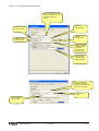
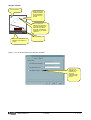
be momentarily connected to the PC with its standard cable. Then start the PM.EXE program (supplied
together with this software) and press the Program modem button. Wait for the confirmation message
and then disconnect the modem from the PC and connect it to the multimeter. The PM.EXE program
transmits the following configuration string to the modem:
AT E0 &N6 &U6 &W0 <CR>
(commands valid for modem model 5630)
If the user is familiar with terminal emulation programs (such as Windows Hyperterminal) this
programming can be done manually without the aid of the PM.EXE program. In this case, it will be
necessary to set the serial interface at 9600 Baud, 8 bit, No parity, 1 stop bit and type in the above string
from the keyboard. On pressing return the modem will answer with OK confirming that programming has
taken place.
2. multimeter configuration
Also the multimeter needs a configuration to be able to converse with the modem.
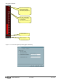
• Check that the internal software revision of the multimeter is higher or equal to 8.0. The software
revision is shown on the displays at power-on.
• From the front panel of each multimeter, enter the serial communication setup menu (see the multimeter
Addendum Manual)
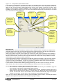
• Check the serial address (parameter P.41). If several Multimeters are connected to a RS-485 bus, set
each of them with a progressive serial address starting from 001.
• On each unit, select the Modbus ASCII protocol (parameter P.44 set to ASC).
• If you want the multimeter to answer when modem rings (modem without auto-answer) then set
parameter P.45 to 001, only for the multimeter with serial address 01.
• Otherwise, if you want the modem to answer automatically itself, then enable the modem auto-answer,
setting its parameter S0 to 001 (with command ATS0=1 &W0) and leave the first multimeter with P45 to
000.
3. System connection
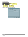
• Connect the multimeter-side modem to the RS232/RS485 interface converter using 51C9 cable.
• Connect the RS232/RS485 interface converter to the multimeter network using a shielded twisted pair
cable (see wiring diagram in the following page).
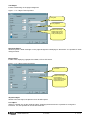
• Connect the second modem to the PC with the standard cable provided with the modem. The PC-side
modem does not require any particular programming (it must be left at factory defaults).
MSGB105$0500.doc
30.10.2009
P. 37 / 39