1
Activation of the PC-multimeters connection
To operate the remote control program, it is essential the PC and multimeter can communicate by serial
interface. To activate the serial link, without using a modem, follow these steps:
1. The first step is to make sure the PC has one free RS-232 serial communications interface port. Serial
ports are normally indicated by the COM reference. They are usually numbered COM1: to COM4:
although the majority of the brands on the market have only two available ports, COM1: and COM2:,
identifiable by the 9-pin D-type male connector. Secondly, it is important to choose the PC port bearing
in mind that one serial port is already used for the mouse in some cases.
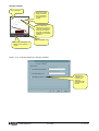
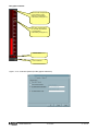
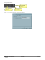
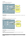
1. Configure the software to use the selected serial port. This can be done when the multimeter.exe
software is executed for the first time and also later, using Configuration-Options-General menu (see the
Configuration chapter). The factory default for the serial port is COM1: , 9600 baud, no parity.
2. Prepare the Rs-485 network. Connect the Rs-232/Rs-485 converter to the PC. Connect all multimeters
interface terminals in parallel with the twisted-pair cable and then to the interface converter, as shown in
the following wiring diagram. Make sure the polarity is correct ( A and B terminals).
3. We strongly recommend to use an interface converter supplied by Lovato. If the user wants to use an
interface converter of another brand, we will not able to help with wiring, nor to assure that the
communication will work properly. However, the interface converter must be insulated and have an
automatic enable line control circuit.
4. From the front keyboard of each multimeter, enter the communication setup and set one different serial
address for each multimeter-DMG, starting from address 01. Make sure that the PC speed and parity
settings match the multimeters setting.
5. At this point it is possible to start the Remote control application. If the wiring and settings are correct,
the link will be automatically established with the first multimeter.
Wiring diagram (direct connection)
PC
TR A B SG
RS485
DMK n°31
TR A B SG
TR A B SG
RS485
DMK n°1
PX1
Troubleshooting
If the connection does not work (trying to enter Online mode, the program emits some beeps and
automatically proceeds in Offline mode), carefully check the following points:
1. The PC COM port used for the connection must match the one selected in Configuration-OptionsGeneral-Serial port settings menu. That port must NOT be configured as a serial mouse port on the PC.
2. The communication rate set on the PC and all Multimeters must be the same (e.g. 9600 bps for both).
3. If there are more than one multimeter connected, then each must have a serial address different than all
the others (e.g. 01, 02, 03, etc.). To set the serial address, program the relative parameter in the
communication setup menu.
4. The converter connection polarity to the RS-485 bus must be correct; all A terminals (marked on the
leads), plugged on to one bus connector and the B terminals with the other.
5. The maximum distance between the two most distant units on the RS-485 bus must not exceed 1000 m.
6. The two most distant units must be connected to the terminal resistor (TR).
7. The interface converter on the PC side must be switched on and correctly configured; see the relative
technical sheet attached to the device. In particular, it must be set for automatic enable line switching
(Data mode).
MSGB105$0500.doc
30.10.2009
P. 3 / 39