1
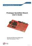
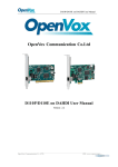
100 Ohm 100x
Digout D3
Tx
GND
Rx
Digin D3
1K
GND 100 Ohm 100x
Figure 4.19: Piezo Transceiver setup measuring velocity of sound
Distance (cm)
4
5
6
7
Timeusec)
224
253
282
310
Dist. dierence
Time di.
Vel. (m/s
1
2
3
29
58
86
344.8
344.8
348.8
Table 4.1: Velocity of sound
on Digital Output Socket D3 to generate a sound wave. The sound wave
reaches the receiver piezo kept several centimeters away and induces a small
voltage across it. This signal is amplied by two variable gain ampliers in
series, each with a gain of 100. The output is fed to Digital Input D3 through
a 1K resistor3 . The interval between the output pulse and the rising edge of
D3 is measured by the following program 'piezo.py'. The output is redirected
to a le
import phm
p=phm.phm()
p.write_outputs(0)
for x in range(10):
print p.pulse2rtime(3,3,13,0)
To avoid gross errors in this experiment one should be aware of the following. Applying one pulse to the transmitter piezo is like banging a metal plate
3 It
is very important to use this resistor. The amplier output is bipolar and goes
negative values. Feeding negative voltage to D3 may damage the micro-controller. The
1KOhm resistor acts as a current limiter for the diode that protects the micro-controller
from negative inputs.
54