1
12
function block goes to the appropriate error state. You must correct the error and then reset the
function block (enable the Reset input power flow) to begin sampling again.
If you select an input module to be scanned the PLC will not verify that the module is a Discrete
Input Module, or that Channel Descriptions associated with the module have valid lengths and
offsets based upon the module size. You must correctly set up the sampling of an Input Module.
Although multiple channel descriptions can target an input module, the module is still only scanned
once per function block execution.
The SER function block can be placed in the normal user logic program or within a periodic
subroutine. If placed in the user logic program, the resolution of the interval between scans is the
resolution of the scan time, which can vary depending on the number and types of functions active
on any particular scan. If placed in an interrupt subroutine, the interval can be set to as little as 1ms,
and the resolution will be highly repeatable at 1ms with little jitter.
Execution time of one function block with a 1ms periodic subroutine can consume up to 50% of the
CPU's resources. You should not plan on execution of more than two SER functions within a 1ms
periodic subroutine.
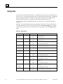
Sampling Modes
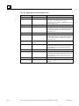
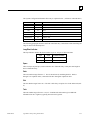
The SER sampling mode is determined by the Trigger Mode (Word 2 in the Function Control
Block) and Number of Samples After Trigger (Word 10) parameters. You will need to interpret the
contents of the sample buffer based on how you configured these parameters.
Trigger-Controlled Sampling
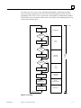
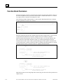
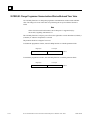
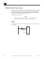
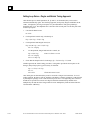
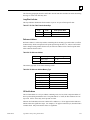
To configure pre-, mid-, and post-trigger sampling modes, Trigger Mode (Word 2 = 0) is selected.
The sampling mode is controlled by the Number of Samples After Trigger (Word 10). In all cases,
sampling starts when the Enable signal goes high. When the Trigger signal goes high, sampling
continues until the Number of Samples After Trigger is collected. The function block Output signal
goes high when sampling is completed.
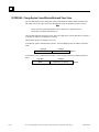
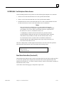
If more than the configured Number of Samples (Word 9) is collected before the Number of
Samples After Trigger condition is satisfied, the buffer “wraps around,” meaning that the SER
returns to the beginning of the buffer and overwrites the initial samples.
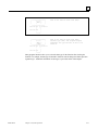
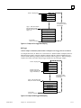
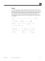
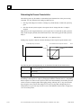
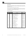
When the trigger first transitions from off to on, the trigger time is placed in a configured location.
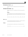
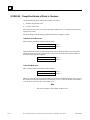
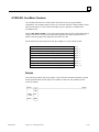
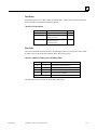
Pre Trigger
Collects samples continuously until trigger is detected.
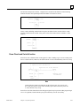
To configure this mode, set Word 10 to a value of 0, so that when the trigger signal is activated,
sampling stops and a time stamp is generated. (All samples collected before the trigger.)
12-14
Series 90-30/20/Micro PLC CPU Instruction Set Reference Manual – June 1999
GFK-0467L