1
GE Fanuc Automation
Programmable Control Products
Series 90™-30/20/Micro PLC
CPU Instruction Set
Reference Manual
GFK-0467L
June 1999
GFL-002
Warnings, Cautions, and Notes
as Used in this Publication
Warning
Warning notices are used in this publication to emphasize that hazardous voltages,
currents, temperatures, or other conditions that could cause personal injury exist in this
equipment or may be associated with its use.
In situations where inattention could cause either personal injury or damage to
equipment, a Warning notice is used.
Caution
Caution notices are used where equipment might be damaged if care is not taken.
Note
Notes merely call attention to information that is especially significant to understanding and
operating the equipment.
This document is based on information available at the time of its publication. While efforts
have been made to be accurate, the information contained herein does not purport to cover all
details or variations in hardware or software, nor to provide for every possible contingency in
connection with installation, operation, or maintenance. Features may be described herein
which are not present in all hardware and software systems. GE Fanuc Automation assumes no
obligation of notice to holders of this document with respect to changes subsequently made.
GE Fanuc Automation makes no representation or warranty, expressed, implied, or statutory
with respect to, and assumes no responsibility for the accuracy, completeness, sufficiency, or
usefulness of the information contained herein. No warranties of merchantability or fitness for
purpose shall apply.
The following are trademarks of GE Fanuc Automation North America, Inc.
Alarm Master
CIMPLICITY
CIMPLICITY 90–ADS
CIMSTAR
Field Control
GEnet
Genius
Helpmate
Logicmaster
Modelmaster
Motion Mate
ProLoop
PROMACRO
PowerMotion
PowerTRAC
Series 90
Series Five
Series One
Series Six
Series Three
VersaMax
VersaPro
VuMaster
Workmaster
©Copyright 1989–1999 GE Fanuc Automation North America, Inc.
All Rights Reserved.
Preface
This manual describes the system operation, fault handling, and Logicmaster 90™ programming
instructions for the Series 90™-30, Series 90-20 and Series 90 Micro programmable logic
controllers. Series 90-30 PLCs, Series 90-20 PLCs, and Series 90 Micro PLCs are members of the
Series 90 family of programmable logic controllers from GE Fanuc Automation.
Revisions to This Manual
•
The Model 364 CPU (release 9.0 and later) supports connection to an Ethernet network
through either of two built-in Ethernet ports. AAUI and 10BaseT ports are provided. The
Model 364 is the only Series 90-30 CPU that supports Ethernet Global Data (p. 2-39).
•
The Hand Held Programmer does not allow you to change the Time of Day clock while key
switch protection is active (p. 2-14).
•
Sweep impact figures for DSM configuration have been added to Chapter 2.
•
Differences in operation for Logarithmic/Exponential (p. 6-12) and Truncate (p. 11-11)
functions have been identified for the CPU352.
•
The Sequential Event Recorder (SER) discussion has been revised to clarify the capabilities of
this function. Detailed timing information for this function is provided in Appendix A. This
function is available on release 9.0 and later of the 35x and 36x series CPUs (p. 12-8).
•
A new service request, Skip Next Output and Input Scan (SVCREQ #45) is available for
release 9.0 and later of the 35x and 36x series CPUs (p. 12-63).
•
The parameter block listings for read and write functions of the Fast Backplane Status Access
service request (SVCREQ #46) have been corrected (p. 12-64).
•
Other corrections and clarifications as necessary.
Content of This Manual
Chapter 1. Introduction: provides an overview of the Series 90-30 PLC, the Series 90-20 PLC,
and the Series 90 Micro PLC systems and the Series 90-30/20/Micro instruction set.
Chapter 2. System Operation: describes certain system operations of the Series 90-30 PLC,
Series 90-20 PLC, or Series 90 Micro systems. This includes a discussion of the PLC system
sweep sequences, the system power-up and power-down sequences, clocks and timers, security,
I/O, and fault handling. It also includes general information for a basic understanding of
programming ladder logic.
Chapter 3. Fault Explanations and Correction: provides troubleshooting information for a
Series 90-30, 90-20, or Micro PLC system. It explains fault descriptions in the PLC fault table and
fault categories in the I/O fault table.
GFK-0467L
iii
Preface
Chapters 4-12. Series 90-30/20/Micro Instruction Set: describe programming instructions
available for Series 90-30 PLCs, Series 90-20 PLCs, and Series 90 Micro PLCs. These chapters
correspond to the main program function groups.
Appendix A. Instruction Timing: lists the memory size in bytes and execution time in
microseconds for each programming instruction. Memory size is the number of bytes required by
the function in a ladder diagram application program.
Appendix B. Interpreting Fault Tables: describes how to interpret the message structure format
when reading the fault tables using Logicmaster 90-30/20/Micro software.
Appendix C. Instruction Mnemonics: lists mnemonics that can be typed to display
programming instructions while searching through or editing a program.
Appendix D. Key Functions: lists the special keyboard assignments used for the Logicmaster
90-30/20/Micro software. A pull-out quick reference card that lists key functions and instruction
mnemonics follows this appendix.
Appendix E. Using Floating-Point Numbers: describes special considerations for using
floating-point math operations.
Related Publications
Logicmaster™ 90 Series 90™-30/20/Micro Programming Software User’s Manual (GFK-0466).
Logicmaster™ 90 Series 90-30 and 90-20 Important Product Information (GFK-0468).
Series 90™-30 Programmable Controller Installation Manual (GFK-0356).
Series 90™-20 Programmable Controller Installation Manual (GFK-0551).
Series 90™-30 I/O Module Specifications Manual (GFK-0898).
Series 90™ Programmable Coprocessor Module and Support Software User’s Manual
(GFK-0255).
Series 90™ PCM Development Software (PCOP) User’s Manual (GFK-0487).
CIMPLICITY™ 90-ADS Alphanumeric Display System User’s Manual (GFK-0499).
CIMPLICITY™ 90-ADS Alphanumeric Display System Reference Manual (GFK-0641).
Alphanumeric Display Coprocessor Module Data Sheet (GFK-0521).
Series 90™-30 and 90-20 PLC Hand-Held Programmer User’s Manual (GFK-0402).
Power Mate APM for Series 90™-30 PLC—Standard Mode User’s Manual (GFK-0840).
Power Mate APM for Series 90™-30 PLC—Follower Mode User’s Manual (GFK-0781).
Motion Mate™ DSM302 for Series 90™-30 PLCs User’s Manual (GFK-1464)
Series 90™-30 High Speed Counter User’s Manual (GFK-0293).
Series 90™-30 Genius Communications Module User’s Manual (GFK-0412).
Genius Communications Module Data Sheet (GFK-0272).
iv
Series 90™-30/20/Micro PLC CPU Instruction Set Reference Manual–June 1999
GFK-0467L
Preface
Series 90™-30 Genius™ Bus Controller User’s Manual (GFK-1034).
Series 90™-70 FIP Bus Controller User’s Manual (GFK-1038).
Series 90™-30 FIP Remote I/O Scanner User’s Manual (GFK-1037).
Field Control™ Distributed I/O and Control System Genius™ Bus Interface Unit User’s Manual
(GFK-0825).
Series 90™ Micro Programmable Logic Controller User’s Manual (GFK-1065).
Series 90™ PLC Serial Communications User’s Manual (GFK-0582).
We Welcome Your Comments and Suggestions
At GE Fanuc Automation, we strive to produce quality technical documentation. After you have
used this manual, please take a few moments to complete and return the Reader's Comment Card
located on the next page.
Libby Allen
Sr. Technical Writer
GFK-0467L
Preface
v
Contents
Chapter 1
Introduction..................................................................................................... 1-1
Chapter 2
System Operation ............................................................................................ 2-1
Section 1: PLC Sweep Summary .................................................................. 2-2
Standard Program Sweep .............................................................................................. 2-2
Sweep Time Calculation......................................................................................... 2-7
Programmer Communications Window......................................................................... 2-9
System Communications Window .............................................................................. 2-11
PCM Communications with the PLC (Models 331 and Higher)................................... 2-12
DSM Communications with the PLC .......................................................................... 2-12
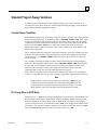
Standard Program Sweep Variations ........................................................................... 2-13
Constant Sweep Time Mode ................................................................................. 2-13
PLC Sweep When in STOP Mode ........................................................................ 2-13
Communication Window Modes........................................................................... 2-14
Key Switch on 35x and 36x Series CPUs: Change Mode and Flash Protect ................. 2-15
Using the Release 7 and Later Key Switch............................................................ 2-15
Clearing the Fault Table with the Key Switch ....................................................... 2-16
Enhanced Memory Protect with Release 8 and Later CPUs................................... 2-16
Section 2: Program Organization and User References/Data ....................2-17
Subroutine Blocks....................................................................................................... 2-18
Examples of Using Subroutine Blocks .................................................................. 2-18
How Blocks Are Called ........................................................................................ 2-19
Periodic Subroutines............................................................................................. 2-19
User References.......................................................................................................... 2-20
Transitions and Overrides ..................................................................................... 2-21
Retentiveness of Data ........................................................................................... 2-21
Data Types ................................................................................................................. 2-22
System Status References ........................................................................................... 2-23
Function Block Structure ............................................................................................ 2-26
Format of Ladder Logic Relays ............................................................................ 2-26
Format of Program Function Blocks ..................................................................... 2-26
Function Block Parameters ......................................................................................... 2-28
Power Flow In and Out of a Function ................................................................... 2-29
Section 3: Power-Up and Power-Down Sequences......................................2-30
Power-Up ................................................................................................................... 2-30
Power-Down............................................................................................................... 2-33
Section 4: Clocks and Timers.......................................................................2-34
Elapsed Time Clock.................................................................................................... 2-34
Time-of-Day Clock..................................................................................................... 2-34
Watchdog Timer......................................................................................................... 2-35
Elapsed Power Down Timer ....................................................................................... 2-35
GFK-0467L
vii
Contents
Constant Sweep Timer................................................................................................ 2-35
Time-Tick Contacts .................................................................................................... 2-36
Section 5: System Security .............................................................................2-37
Passwords................................................................................................................... 2-37
Privilege Level Change Requests ................................................................................ 2-38
Locking/Unlocking Subroutines.................................................................................. 2-38
Permanently Locking a Subroutine ....................................................................... 2-38
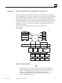
Section 6: Series 90-30, 90-20, and Micro I/O System.................................2-39
Series 90-30 I/O Modules ........................................................................................... 2-40
I/O Data Formats ........................................................................................................ 2-42
Default Conditions for Series 90-30 Output Modules .................................................. 2-42
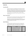
Diagnostic Data .......................................................................................................... 2-42
Global Data ................................................................................................................ 2-43
Genius Global Data .............................................................................................. 2-43
Ethernet Communications.................................................................................... 2-43
Model 20 I/O Modules.......................................................................................... 2-43
Configuration and Programming ................................................................................. 2-44
Chapter 3
Fault Explanation and Correction.................................................................. 3-1
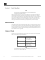
Section 1: Fault Handling .............................................................................. 3-2
Alarm Processor ........................................................................................................... 3-2
Classes of Faults........................................................................................................... 3-2
System Reaction to Faults............................................................................................. 3-3
Fault Tables............................................................................................................ 3-3
Fault Action ........................................................................................................... 3-4
Fault References ........................................................................................................... 3-4
Fault Reference Definitions .......................................................................................... 3-4
Additional Fault Effects ................................................................................................ 3-5
PLC Fault Table Display............................................................................................... 3-5
I/O Fault Table Display ................................................................................................ 3-5
Accessing Additional Fault Information........................................................................ 3-6
Section 2: PLC Fault Table Explanations ..................................................... 3-7
Fault Actions ................................................................................................................ 3-8
Loss of, or Missing, Option Module........................................................................ 3-8
Reset of, Addition of, or Extra, Option Module....................................................... 3-8
System Configuration Mismatch............................................................................. 3-9
Option Module Software Failure........................................................................... 3-10
Program Block Checksum Failure......................................................................... 3-10
Low Battery Signal............................................................................................... 3-10
Constant Sweep Time Exceeded ........................................................................... 3-11
Application Fault.................................................................................................. 3-11
viii
Series 90™-30/20/Micro PLC CPU Instruction Set Reference Manual–June 1999
GFK-0467L
Contents
No User Program Present ..................................................................................... 3-12
Corrupted User Program on Power-Up ................................................................. 3-12
Password Access Failure ...................................................................................... 3-12
PLC CPU System Software Failure....................................................................... 3-13
Communications Failure During Store .................................................................. 3-15
Section 3: I/O Fault Table Explanations ......................................................3-16
Loss of I/O Module..................................................................................................... 3-16
Addition of I/O Module .............................................................................................. 3-17
Chapter 4
Relay Functions ............................................................................................... 4-1
Using Contacts ............................................................................................................. 4-1
Using Coils................................................................................................................... 4-2
Normally Open Contact —| |— .................................................................................... 4-3
Normally Closed Contact —|/|—.................................................................................. 4-3
Coil —( )— ................................................................................................................. 4-3
Example ................................................................................................................. 4-3
Negated Coil —(/)— ................................................................................................... 4-4
Example ................................................................................................................. 4-4
Retentive Coil —(M)— ............................................................................................... 4-4
Negated Retentive Coil —(/M)— ................................................................................ 4-4
Positive Transition Coil —(↑)—.................................................................................. 4-4
Negative Transition Coil —(↓)— ................................................................................ 4-5
Example ................................................................................................................. 4-5
SET Coil —(S) — ....................................................................................................... 4-5
RESET Coil —(R)— ................................................................................................... 4-5
Example ................................................................................................................. 4-6
Retentive SET Coil —(SM)— ..................................................................................... 4-6
Retentive RESET Coil —(RM)— ................................................................................ 4-6
Links ............................................................................................................................ 4-7
Example ................................................................................................................. 4-7
Continuation Coils (———<+>) and Contacts (<+>———) ........................................ 4-8
Chapter 5
Timers and Counters....................................................................................... 5-1
Function Block Data Required for Timers and Counters................................................ 5-1
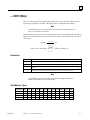
ONDTR........................................................................................................................ 5-3
Parameters.............................................................................................................. 5-4
Valid Memory Types.............................................................................................. 5-4
Example ................................................................................................................. 5-5
TMR ............................................................................................................................ 5-5
Parameters.............................................................................................................. 5-6
Valid Memory Types.............................................................................................. 5-6
Example ................................................................................................................. 5-7
GFK-0467L
Contents
ix
Contents
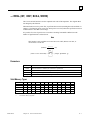
OFDT........................................................................................................................... 5-8
Parameters.............................................................................................................. 5-9
Valid Memory Types............................................................................................ 5-10
Example ............................................................................................................... 5-10
UPCTR ...................................................................................................................... 5-11
Parameters............................................................................................................ 5-11
Valid Memory Types............................................................................................ 5-12
Example ............................................................................................................... 5-12
DNCTR...................................................................................................................... 5-12
Parameters............................................................................................................ 5-13
Valid Memory Types............................................................................................ 5-13
Example ............................................................................................................... 5-13
Example ............................................................................................................... 5-14
Chapter 6
Math Functions ............................................................................................... 6-1
Standard Math Functions (ADD, SUB, MUL, DIV) ...................................................... 6-2
Parameters.............................................................................................................. 6-3
Valid Memory Types.............................................................................................. 6-3
Example ................................................................................................................. 6-3
Math Functions and Data Types.............................................................................. 6-4
Example ................................................................................................................. 6-5
MOD (INT, DINT) ................................................................................................... 6-6
Parameters.............................................................................................................. 6-6
Valid Memory Types.............................................................................................. 6-7
Example ................................................................................................................. 6-7
SQRT (INT, DINT, REAL) ...................................................................................... 6-8
Parameters.............................................................................................................. 6-8
Valid Memory Types.............................................................................................. 6-9
Example ................................................................................................................. 6-9
Trig Functions (SIN, COS, TAN, ASIN, ACOS, ATAN) ........................................ 6-10
Parameters............................................................................................................ 6-11
Valid Memory Types............................................................................................ 6-11
Example ............................................................................................................... 6-11
Logarithmic/Exponential Functions (LOG, LN, EXP, EXPT) ..................................... 6-12
Parameters............................................................................................................ 6-12
Valid Memory Types............................................................................................ 6-13
Example ............................................................................................................... 6-13
Radian Conversion (RAD, DEG) ............................................................................ 6-14
Parameters............................................................................................................ 6-14
Valid Memory Types............................................................................................ 6-14
Example ............................................................................................................... 6-15
x
Series 90™-30/20/Micro PLC CPU Instruction Set Reference Manual–June 1999
GFK-0467L
Contents
Chapter 7
Relational Functions........................................................................................ 7-1
Standard Relational Functions (EQ, NE, GT, GE, LT, LE)............................................ 7-2
Parameters.............................................................................................................. 7-2
Expanded Description............................................................................................. 7-3
Valid Memory Types.............................................................................................. 7-3
Example ................................................................................................................. 7-3
RANGE (INT, DINT, WORD) ................................................................................. 7-4
Parameters.............................................................................................................. 7-5
Valid Memory Types.............................................................................................. 7-5
Example 1 .............................................................................................................. 7-5
Example 2 .............................................................................................................. 7-6
Chapter 8
Bit Operation Functions.................................................................................. 8-1
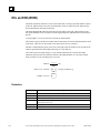
AND and OR (WORD)................................................................................................. 8-3
Parameters.............................................................................................................. 8-3
Valid Memory Types.............................................................................................. 8-4
Example ................................................................................................................. 8-4
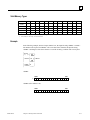
XOR (WORD).............................................................................................................. 8-5
Parameters.............................................................................................................. 8-5
Valid Memory Types.............................................................................................. 8-6
Example ................................................................................................................. 8-6
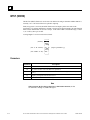
NOT (WORD).............................................................................................................. 8-7
Parameters.............................................................................................................. 8-7
Valid Memory Types.............................................................................................. 8-7
Example ................................................................................................................. 8-7
SHL and SHR (WORD)................................................................................................ 8-8
Parameters.............................................................................................................. 8-9
Valid Memory Types.............................................................................................. 8-9
Example ................................................................................................................. 8-9
ROL and ROR (WORD)............................................................................................. 8-10
Parameters............................................................................................................ 8-10
Valid Memory Types............................................................................................ 8-11
Example ............................................................................................................... 8-11
BTST (WORD) .......................................................................................................... 8-12
Parameters............................................................................................................ 8-12
Valid Memory Types............................................................................................ 8-13
Example ............................................................................................................... 8-13
BSET and BCLR (WORD)......................................................................................... 8-14
Parameters............................................................................................................ 8-14
Valid Memory Types............................................................................................ 8-15
Example ............................................................................................................... 8-15
BPOS (WORD) .......................................................................................................... 8-16
GFK-0467L
Contents
xi
Contents
Parameters............................................................................................................ 8-16
Valid Memory Types............................................................................................ 8-17
Example ............................................................................................................... 8-17
MSKCMP (WORD, DWORD)................................................................................... 8-18
Parameters............................................................................................................ 8-19
Valid Memory Types............................................................................................ 8-19
Example ............................................................................................................... 8-20
Chapter 9
Data Move Functions ...................................................................................... 9-1
MOVE (BIT, INT, WORD, REAL) .............................................................................. 9-2
Parameters.............................................................................................................. 9-3
Example 1 .............................................................................................................. 9-4
Example 2 .............................................................................................................. 9-4
BLKMOV (INT, WORD, REAL) ................................................................................. 9-5
Parameters.............................................................................................................. 9-5
Valid Memory Types.............................................................................................. 9-6
Example ................................................................................................................. 9-6
BLKCLR (WORD)....................................................................................................... 9-7
Parameters.............................................................................................................. 9-7
Valid Memory Types.............................................................................................. 9-7
Example ................................................................................................................. 9-7
SHFR (BIT, WORD) .................................................................................................... 9-8
Parameters.............................................................................................................. 9-9
Valid Memory Types.............................................................................................. 9-9
Example 1 ............................................................................................................ 9-10
Example 2 ............................................................................................................ 9-10
BITSEQ (BIT)........................................................................................................ 9-11
Memory Required for a Bit Sequencer .................................................................. 9-11
Parameters............................................................................................................ 9-12
Valid Memory Types............................................................................................ 9-13
Example ............................................................................................................... 9-13
COMMREQ ............................................................................................................... 9-14
Command Block................................................................................................... 9-14
Parameters............................................................................................................ 9-15
Valid Memory Types............................................................................................ 9-15
Example ............................................................................................................... 9-16
Chapter 10
Table Functions ..............................................................................................10-1
ARRAY_MOVE (INT, DINT, BIT, BYTE, WORD).................................................. 10-2
Parameters............................................................................................................ 10-3
Valid Memory Types............................................................................................ 10-3
Example 1 ............................................................................................................ 10-4
xii
Series 90™-30/20/Micro PLC CPU Instruction Set Reference Manual–June 1999
GFK-0467L
Contents
Example 2 ............................................................................................................ 10-4
Example 3 ............................................................................................................ 10-5
Search Functions ........................................................................................................ 10-6
Parameters............................................................................................................ 10-7
Valid Memory Types............................................................................................ 10-7
Example 1 ............................................................................................................ 10-7
Example 2 ............................................................................................................ 10-8
Chapter 11
Conversion Functions.....................................................................................11-1
—>BCD-4 (INT)........................................................................................................ 11-2
Parameters............................................................................................................ 11-2
Valid Memory Types............................................................................................ 11-2
Example ............................................................................................................... 11-2
—>INT (BCD-4, REAL) ........................................................................................ 11-3
Parameters............................................................................................................ 11-3
Valid Memory Types............................................................................................ 11-3
Example ............................................................................................................... 11-4
—>DINT (REAL) ...................................................................................................... 11-5
Parameters............................................................................................................ 11-5
Valid Memory Types............................................................................................ 11-5
Example ............................................................................................................... 11-6
—>REAL (INT, DINT, BCD-4, WORD) .................................................................. 11-7
Parameters............................................................................................................ 11-7
Valid Memory Types............................................................................................ 11-7
Example ............................................................................................................... 11-8
—>WORD (REAL).................................................................................................... 11-9
Parameters............................................................................................................ 11-9
Valid Memory Types............................................................................................ 11-9
Example ............................................................................................................. 11-10
TRUN (INT, DINT) ................................................................................................. 11-11
Parameters.......................................................................................................... 11-11
Valid Memory Types.......................................................................................... 11-11
Example ............................................................................................................. 11-12
Chapter 12
Control Functions...........................................................................................12-1
CALL......................................................................................................................... 12-2
Example ............................................................................................................... 12-2
DOIO ......................................................................................................................... 12-3
Parameters............................................................................................................ 12-4
Valid Memory Types............................................................................................ 12-4
Input Example 1 ................................................................................................... 12-5
Input Example 2 ................................................................................................... 12-5
GFK-0467L
Contents
xiii
Contents
Output Example 1................................................................................................. 12-6
Output Example 2................................................................................................. 12-6
Enhanced DO I/O Function for 331 and Later CPUs ................................................... 12-7
SER............................................................................................................................ 12-8
Features................................................................................................................ 12-8
Sample SER Function Block................................................................................. 12-8
Parameters............................................................................................................ 12-9
Valid Memory Types............................................................................................ 12-9
Function Control Block ...................................................................................... 12-10
Status Extra Data States...................................................................................... 12-12
SER Data Block Format ..................................................................................... 12-13
SER Operation ................................................................................................... 12-13
Sampling Modes................................................................................................. 12-14
SER Example ..................................................................................................... 12-16
SER Function Block Trigger Timestamp Formats............................................... 12-20
END ......................................................................................................................... 12-21
Example ............................................................................................................. 12-21
MCRN/MCR............................................................................................................ 12-22
CPU Compatibility ............................................................................................. 12-22
MCRN Operation ............................................................................................... 12-22
MCR Operation.................................................................................................. 12-23
Parameters.......................................................................................................... 12-23
Differences Between MCRs and JUMPs............................................................. 12-23
Example ............................................................................................................. 12-24
ENDMCRN/ENDMCR ............................................................................................ 12-25
Example ............................................................................................................. 12-25
JUMP ....................................................................................................................... 12-26
Examples............................................................................................................ 12-27
LABEL..................................................................................................................... 12-28
Example ............................................................................................................. 12-28
COMMENT ............................................................................................................. 12-29
SVCREQ.................................................................................................................. 12-30
SVC REQ Overview........................................................................................... 12-31
SVCREQ #1: Change/Read Constant Sweep Timer ........................................... 12-33
SVCREQ #2: Read Window Values .................................................................. 12-36
SVCREQ #3: Change Programmer Communications Window Mode and Timer Value12-38
SVCREQ #4: Change System Comm Window Mode and Timer Value.............. 12-40
SVCREQ #6: Change/Read Number of Words to Checksum............................. 12-42
SVCREQ #7: Change/Read Time-of-Day Clock ................................................ 12-44
SVCREQ #8: Reset Watchdog Timer ................................................................ 12-48
SVCREQ #9: Read Sweep Time from Beginning of Sweep ............................... 12-49
SVCREQ #10: Read Folder Name ..................................................................... 12-50
xiv
Series 90™-30/20/Micro PLC CPU Instruction Set Reference Manual–June 1999
GFK-0467L
Contents
SVCREQ #11: Read PLC ID ............................................................................. 12-51
SVCREQ #12: Read PLC Run State .................................................................. 12-52
SVCREQ #13: Shut Down (Stop) PLC .............................................................. 12-53
SVCREQ #14: Clear Fault Tables...................................................................... 12-54
SVCREQ #15: Read Last-Logged Fault Table Entry.......................................... 12-55
SVCREQ #16: Read Elapsed Time Clock .......................................................... 12-59
SVCREQ #18: Read I/O Override Status ........................................................... 12-60
SVCREQ #23: Read Master Checksum ............................................................. 12-61
SVCREQ #26/30: Interrogate I/O ...................................................................... 12-62
SVCREQ #29: Read Elapsed Power Down Time ............................................... 12-63
SVCREQ #45: Skip Next Output & Input Scan.................................................. 12-64
SVCREQ #46: Fast Backplane Status Access .................................................... 12-65
PID........................................................................................................................... 12-71
Parameters.......................................................................................................... 12-72
Valid Memory Types.......................................................................................... 12-72
PID Parameter Block .......................................................................................... 12-73
Operation of the PID Instruction ......................................................................... 12-75
Appendix A
Instruction Timing ..........................................................................................A-1
Instruction Sizes for High Performance CPUs...................................................... A-11
Boolean Execution Times .......................................................................................... A-11
Appendix B
Interpreting Fault Tables................................................................................B-1
PLC Fault Table .......................................................................................................... B-1
I/O Fault Table ............................................................................................................ B-8
Appendix C
Instruction Mnemonics ...................................................................................C-1
Appendix D
Key Functions..................................................................................................D-1
Appendix E
Using Floating-Point Numbers .......................................................................E-1
Floating-Point Numbers..........................................................................................E-1
Internal Format of Floating-Point Numbers.............................................................E-3
Values of Floating-Point Numbers..........................................................................E-4
Entering and Displaying Floating-Point Numbers ...................................................E-5
Errors in Floating-Point Numbers and Operations ...................................................E-6
GFK-0467L
Contents
xv
Contents
Figure 2-1. PLC Sweep ........................................................................................................................... 2-3
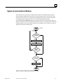
Figure 2-2. Programmer Communications Window Flow Chart............................................................. 2-10
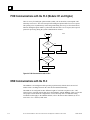
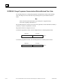
Figure 2-3. System Communications Window Flow Chart..................................................................... 2-11
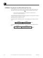
Figure 2-4. PCM Communications with the PLC ................................................................................... 2-12
Figure 2-5. Power-Up Sequence ............................................................................................................ 2-31
Figure 2-6. Time-Tick Contact Timing Diagram.................................................................................... 2-36
Figure 2-7. Series 90-30 I/O Structure ................................................................................................... 2-39
Figure 2-8. Series 90-30 I/O Modules .................................................................................................... 2-40
Figure 12-1. Example of Pre-Trigger SER Sampling............................................................................ 12-15
Figure 12-2. Example of Mid-Trigger SER Sampling .......................................................................... 12-15
Figure 12-3. Post-Trigger SER Sampling............................................................................................. 12-16
Figure 12-4. Independent Term Algorithm (PIDIND) .......................................................................... 12-80
xvi
Series 90™-30/20/Micro PLC CPU Instruction Set Reference Manual–June 1999
GFK-0467L
Contents
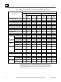
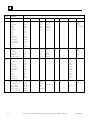
Table 2-1. Sweep Time Contribution ....................................................................................................... 2-4
Table 2-2. I/O Scan Time Contributions for the 90-30 35x and 36x Series (in milliseconds)..................... 2-5
Table 2-3. I/O Scan Time Contributions for the 90-30 Series up to 341 (in milliseconds) ......................... 2-6
Table 2-4. Register References .............................................................................................................. 2-20
Table 2-5. Discrete References .............................................................................................................. 2-20
Table 2-5. Discrete References - Continued ........................................................................................... 2-21
Table 2-6. Data Types ........................................................................................................................... 2-22
Table 2-7. System Status References ..................................................................................................... 2-23
Table 2-7. System Status References - Continued .................................................................................. 2-24
Table 2-7. System Status References - Continued .................................................................................. 2-25
Table 2-8. Series 90-30 I/O Modules ..................................................................................................... 2-40
Table 2-8. Series 90-30 I/O Modules - Continued .................................................................................. 2-41
Table 2-8. Series 90-30 I/O Modules - Continued .................................................................................. 2-42
Table 3-1. Fault Summary ....................................................................................................................... 3-3
Table 3-2. Fault Actions .......................................................................................................................... 3-4
Table 4-1. Types of Contacts................................................................................................................... 4-1
Table 4-2. Types of Coils ........................................................................................................................ 4-2
Table 12-1. Function Control Block for SER Example......................................................................... 12-17
Table 12-2. Sample Contents for SER Example ................................................................................... 12-19
Table 12-3. Data Block for SER Control Block Example ..................................................................... 12-19
Table 12-4. Service Request Functions ................................................................................................ 12-30
Table 12-5. Output Values for Read Extra Data Function..................................................................... 12-66
Table 12-6. Output Values for Write Data Function ............................................................................. 12-67
Table 12-7. Output Values for Read/Write Data Function .................................................................... 12-68
Table 12-8. PID Parameters Overview................................................................................................. 12-73
Table 12-8. PID Parameters Overview - Continued.............................................................................. 12-74
Table 12-9. PID Parameter Details ...................................................................................................... 12-76
Table 12-9. PID Parameter Details - Continued ................................................................................... 12-77
Table 12-9. PID Parameter Details - Continued ................................................................................... 12-78
Table A-1. Instruction Timing, Standard Models .................................................................................... A-2
Table A-1. Instruction Timing, Standard Models-Continued ................................................................... A-3
Table A-1. Instruction Timing, Standard Models-Continued ................................................................... A-4
Table A-1. Instruction Timing, Standard Models-Continued ................................................................... A-5
Table A-2. Instruction Timing, High Performance Models...................................................................... A-6
Table A-2. Instruction Timing, High Performance Models-Continued..................................................... A-7
Table A-2. Instruction Timing, High Performance Models-Continued..................................................... A-8
GFK-0467L
Contents
xvii
Contents
Table A-2. Instruction Timing, High Performance Models-Continued..................................................... A-9
Table A-3. SER Function Block Timing ............................................................................................... A-10
Table A-4. Instruction Sizes for 350—352, 360, 363, and 364 CPUs .................................................... A-11
Table B-1. PLC Fault Groups ................................................................................................................. B-4
Table B-2. PLC Fault Actions ................................................................................................................ B-5
Table B-3. Alarm Error Codes for PLC CPU Software Faults ................................................................. B-5
Table B-4. Alarm Error Codes for PLC Faults ........................................................................................ B-6
Table B-5. PLC Fault Data - Illegal Boolean Opcode Detected ............................................................... B-7
Table B-6. PLC Fault Time Stamp.......................................................................................................... B-7
Table B-7. I/O Fault Table Format Indicator Byte................................................................................... B-9
Table B-8. I/O Reference Address .......................................................................................................... B-9
Table B-9. I/O Reference Address Memory Type ................................................................................... B-9
Table B-10. I/O Fault Groups ............................................................................................................... B-10
Table B-11. I/O Fault Actions .............................................................................................................. B-11
Table B-12. I/O Fault Specific Data...................................................................................................... B-11
Table B-13. I/O Fault Time Stamp........................................................................................................ B-12
Table E-1. General Case of Power Flow for Floating-Point Operations ....................................................E-7
xviii
Series 90™-30/20/Micro PLC CPU Instruction Set Reference Manual–June 1999
GFK-0467L
Chapter
Introduction
1
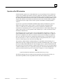
The Series 90-30, 90-20, and Micro PLCs are members of the GE Fanuc Series 90 family of
Programmable Logic Controllers (PLCs). They are easy to install and configure, offer advanced
programming features, and are compatible with the Series 90-70 PLCs.
The Series 90-20 PLC provides a cost-effective platform for low I/O count applications. The
primary objectives of the Series 90-20 PLC are as follows:
•
To provide a small PLC that is easy to use, install, upgrade, and maintain.
•
To provide a cost-effective family-compatible PLC.
•
To provide easier system integration through standard communication hardware and
protocols.
The Series 90 Micro PLC also provides a cost-effective platform for lower I/O count applications.
The primary objectives of the Micro PLC are the same as those for the Series 90-20. In addition,
the Micro offers the following:
•
The Micro PLC has the CPU, power supply, inputs and outputs all built into one small device.
•
Most models also have a high speed counter.
•
Because the CPU, power supply, inputs and outputs all built into one device, it is very easy to
configure.
The software structure for the 341 and lower Series 90-30 PLCs and Series 90-20 PLC uses an
architecture that manages memory and execution priority in the 80188 microprocessor. The 35x
and 36x series of 90-30 PLCs use an 80386EX microprocessor. The Series 90 Micro PLC uses
the H8 microprocessor. This operation supports both program execution and basic housekeeping
tasks such as diagnostic routines, input/output scanners, and alarm processing. The system
software also contains routines to communicate with the programmer. These routines provide for
the upload and download of application programs, return of status information, and control of the
PLC.
In the Series 90-30 PLC, the application (user logic) program that controls the end process to
which the PLC is applied is controlled by a dedicated Instruction Sequencer Coprocessor (ISCP).
The ISCP is implemented in hardware in the Model 313 and higher and in software in the Model
311 systems, and the Micro PLC. The 80188 microprocessor and the ISCP can execute
simultaneously, allowing the microprocessor to service communications while the ISCP is
executing the bulk of the application program; however, the microprocessor must execute the nonBoolean function blocks.
GFK-0467L
1-1
1
Faults occur in the Series 90-30 PLC, Series 90-20 PLC, and the Micro PLC when certain failures
or conditions happen that affect the operation and performance of the system. These conditions
may affect the ability of the PLC to control a machine or process. Other conditions may only act
as an alert, such as a low battery signal to indicate that the voltage of the battery protecting the
memory is low and should be replaced. The condition or failure is called a fault.
Faults are handled by a software alarm processor function that records the faults in either the PLC
fault table or the I/O fault table. (Model 331 and higher CPUs also time-stamp the faults.) These
tables can be displayed through the programming software on the PLC Fault Table and I/O Fault
Table screens in Logicmaster 90-30/20/Micro software using the control and status functions.
Note
Floating-point capabilities are only supported on the 35x and 36x series CPUs,
Release 9 or later, and on all releases of CPU352.
The Model 364 CPU (release 9.10 or later) is the only Series 90-30 CPU that
supports EGD.
Note
For additional information, see the appendices in the back of this manual.
1-2
•
Appendix A lists the memory size in bytes and the execution time in
microseconds for each programming instruction.
•
Appendix B describes how to interpret the message structure format when
reading the PLC and I/O fault tables.
•
Appendix C lists instruction mnemonics for searching or editing a program.
•
Appendix D lists the special keyboard assignments used in the Logicmaster
90-30/20/Micro Software.
•
Appendix E describes the use of floating-point math operations.
Series 90™-30/20/Micro PLC CPU Instruction Set Reference Manual – June 1999
GFK-0467L
Chapter
System Operation
2
This chapter describes certain system operations of the Series 90-30, 90-20, and Micro PLC
systems. These system operations include:
GFK-0467L
•
A summary of PLC sweep sequences (Section 1) ................................................. 2-2
•
Program organization and user references/data (Section 2) ................................ 2-17
•
Power-up and power-down sequences (Section 3) .............................................. 2-30
•
Clocks and timers (Section 4) ............................................................................ 2-34
•
System security through password assignment (Section 5) ................................. 2-37
•
Series 90-30 I/O modules (Section 6)................................................................. 2-39
2-1
2
Section 1: PLC Sweep Summary
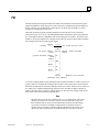
The logic program in the Series 90-30, 90-20, and Micro PLCs execute repeatedly until stopped
by a command from the programmer or a command from another device. The sequence of
operations necessary to execute a program one time is called a sweep. In addition to executing the
logic program, the sweep includes obtaining data from input devices, sending data to output
devices, performing internal housekeeping, servicing the programmer, and servicing other
communications.
Series 90-30, 90-20, and Micro PLCs normally operate in STANDARD PROGRAM SWEEP
mode. Other operating modes include STOP WITH I/O DISABLED mode, STOP WITH I/O
ENABLED mode, and CONSTANT SWEEP mode. Each of these modes, described in this
chapter, is controlled by external events and application configuration settings. The PLC makes
the decision regarding its operating mode at the start of every sweep.
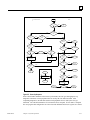
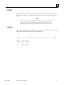
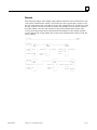
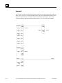
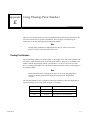
Standard Program Sweep
STANDARD PROGRAM SWEEP mode normally runs under all conditions. The CPU operates by
executing an application program, updating I/O, and performing communications and other tasks.
This occurs in a repetitive cycle called the CPU sweep. There are seven parts to the execution
sequence of the Standard Program Sweep:
2-2
1.
Start-of-sweep housekeeping
2.
Input scan (read inputs)
3.
Application program logic solution
4.
Output scan (update outputs)
5.
Programmer service
6.
Non-programmer service
7.
Diagnostics
Series 90-30/20/Micro PLC CPU Instruction Set Reference Manual – June 1999
GFK-0467L
2
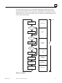
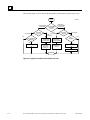
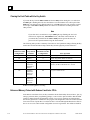
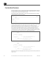
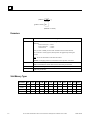
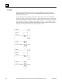
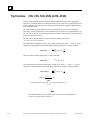
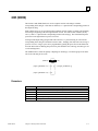
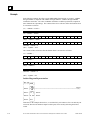
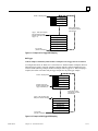
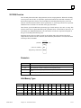
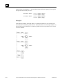
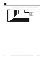
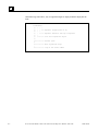
All of these steps execute every sweep. Although the Programmer Communications Window
opens each sweep, programmer services only occur if a board fault has been detected or if the
programming device issues a service request; that is, the Programmer Communications Window
first checks for work to do and exits if there is none. The sequence of the standard program sweep
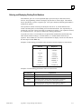
is shown in the following figure.
a43064
START-OF-SWEEP
HOUSEKEEPING
I/O
ENABLED
?
HOUSEKEEPING
NO
YES
DATA
INPUT
INPUT SCAN
RUN
MODE
?
NO
YES
LOGIC SOLUTION
I/O
ENABLED
?
PROGRAM
EXECUTION
SCAN
TIME
OF
PLC
NO
YES
DATA
OUTPUT
OUTPUT SCAN
PROGRAMMER
COMMUNICATIONS
PROGRAMMER
SERVICE
SYSTEM
COMMUNICATIONS
SYSTEM
COMMUNICATIONS
USER PROGRAM
CHECKSUM
CALCULATION
DIAGNOSTICS
START NEXT SWEEP
Figure 2-1. PLC Sweep
GFK-0467L
Chapter 2 System Operation
2-3
2
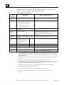
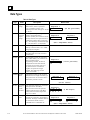
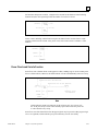
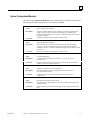
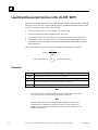
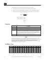
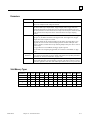
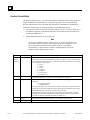
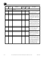
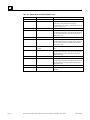
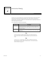
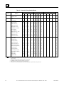
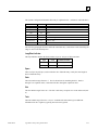
As shown in the PLC sweep sequence, several items are included in the sweep. These items
contribute to the total sweep time as shown in the following table.
Table 2-1. Sweep Time Contribution
Sweep
Element
Description
Time Contribution (ms) 4
351, 352, 350, and 36x series (times for 350 and 36x series
estimated to be the same)
Housekeeping
Calculate sweep time.
•
Schedule start of next sweep.
•
Determine mode of next sweep.
•
Update fault reference tables.
•
Reset watchdog timer.
0.279
Data Input
Input data is received from input and
option modules.
See Table 2-2 for scan time contributions.
Program
Execution
User logic is solved.
Execution time is dependent upon the length of the program
and the type of instructions used in the
program. Instruction execution times are listed in
Appendix A.
Data Output
Output data is sent to output and option
modules.
See Table 2-2 for scan time contributions.
Service External
Devices
Service requests from
programming devices and
intelligent modules are
processed. 1
HHP
0.334
LM-90
0.517
PCM 2
0.482
Reconfiguration
Diagnostics
2-4
•
Slots with faulted modules and empty slots 0.3196
are monitored.
Verify user program integrity
0.010 per word checksummed each sweep3, 7
1.
The scan time contribution of external device service is dependent upon the mode of the communications window in which
the service is processed. If the window mode is LIMITED, a maximum of 8 milliseconds for the 311, 313, 323, and 331
CPUs and 6 milliseconds for the 340 and higher CPUs will be spent during that window. If the window mode is RUNTO-COMPLETION, a maximum of 50 ms can be spent in that window, depending upon the number of requests which are
presented simultaneously.
2.
These measurements were taken with the PCM physically present but not configured and with no application task running
on the PCM.
3.
The number of words checksummed each sweep can be changed with the SVCREQ function block.
4.
These measurements were taken with an empty program and the default configuration. The Series 90-30 PLCs were in an
empty 10-slot rack with no extension racks connected. Also, the times in this table assume that there is no periodic
subroutine active; the times will be larger if a periodic subroutine is active.
5.
The data input time for the Micro PLC can be determined as follows: 0.365 ms. (fixed scan) +
0.036 ms. (filter time) x (total sweep time)/0.5 ms.
6.
Since the Micro PLC has a static set of I/O, reconfiguration is not necessary.
7.
Since the user program for the Micro PLC is in Flash memory, it will not be checked for
integrity.
Series 90-30/20/Micro PLC CPU Instruction Set Reference Manual – June 1999
GFK-0467L
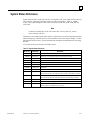
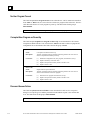
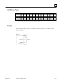
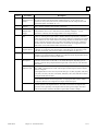
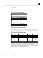
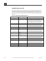
2
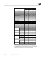
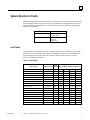
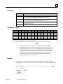
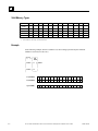
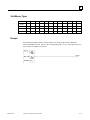
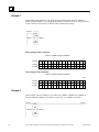
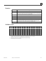
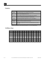
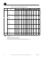
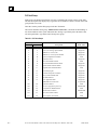
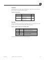
Table 2-2. I/O Scan Time Contributions for the 90-30 35x and 36x Series (in milliseconds)
35x and 36x Series CPUs
Module Type
8-point discrete input
16-point discrete input
32-point discrete input
8-point discrete output
16-point discrete output
32-point discrete output
Combination discrete input/output
4-channel analog input
2-channel analog output
16-channel analog input
(current or voltage)
8-channel analog output
Combination analog input/output
High Speed Counter
I/O Processor
Ethernet Interface (no connection)
Power Mate APM (1-axis)
Power Mate APM (2-axis)
DSM 302 *
GCM
GCM+
GBC
PCM 311
ADC (no task)
I/O Link Master
I/O Link Slave
40 AI, 6 AQ
50AI, 9 AQ
64 AI, 12 AQ
no devices
8 64-word devices
no devices
32 64-word devices
no devices
32 64-word devices
not configured, or
no application task
read 128 %R as
fast as possible
no devices
16 64-point
devices
32-point
64-point
Main
Rack
Expansion
Rack
Remote
Rack
.030
.030
.043
.030
.030
.042
.060
.075
.058
.978
.055
.055
.073
.053
.053
.070
.112
.105
.114
1.446
.206
.206
.269
.197
.197
.259
.405
.396
.402
3.999
1.274
1.220
1.381
1.574
.038
1.527
1.988
1.999
2.106
2.402
.041
2.581
4.472
4.338
5.221
6.388
.053
6.388
1.807
2.143
2.427
2.864
2.864
3.315
3.732
4.317
7.805
9.527
11.092
13.138
.911
8.826
.567
1.714
.798
18.382
.476
1.637
16.932
.866
2.514
1.202
25.377
N/A
5.020
21.179
1.830
5.783
2.540
70.777
N/A
.485
N/A
N/A
.476
.569
4.948
N/A
.865
7.003
N/A
1.932
19.908
.087
.154
.146
.213
.553
.789
* For applications where the DSM’s contributions to scan time will affect machine
operation you may need to use the Do I/O function block, and the Suspend I/O and
Fast Backplane Status Access service requests to transfer necessary data to and from
the Motion module without getting all the data every scan. Refer to the Motion Mate
DSM302 for Series 90-30 PLCs User’s Manual, GFK1464 for details.
GFK-0467L
Chapter 2 System Operation
2-5
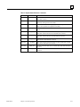
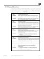
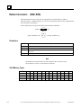
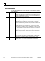
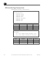
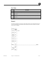
2
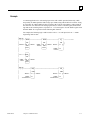
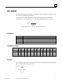
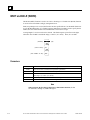
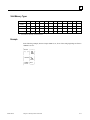
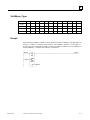
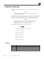
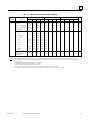
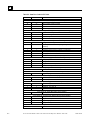
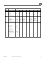
Table 2-3. I/O Scan Time Contributions for the 90-30 Series up to 341 (in milliseconds)
CPU Model
Module Type
331
311/313
Main
Rack
Expansion
Rack
340/341
Remote
Rack
Main
Rack
Expansion
Rack
Remote
Rack
8-point discrete input
.076
.054
.095
.255
.048
.089
.249
16-point discrete input
.075
.055
.097
.257
.048
.091
.250
32-point discrete input
.094
.094
.126
.335
.073
.115
.321
8-point discrete output
.084
.059
.097
.252
.053
.090
.246
16-point discrete output
.083
.061
.097
.253
.054
.090
.248
32-point discrete output
.109
.075
.129
.333
.079
.114
.320
8-point combination input/output
.165
.141
.218
.529
.098
.176
.489
4-channel analog input
.151
.132
.183
.490
.117
.160
.462
2-channel analog output
.161
.138
.182
.428
.099
.148
.392
High-Speed Counter
2.070
2.190
2.868
5.587
1.580
2.175
4.897
Power Mate APM (1-axis)
2.330
2.460
3.175
6.647
1.750
2.506
5.899
Power Mate APM (2-axis)
3.181
3.647
4.497
9.303
2.154
3.097
7.729
DSM 302
40 AI, 6 AQ
3.613
4.081
5.239
11.430
2.552
3.648
9.697
50AI, 9 AQ
4.127
4.611
5.899
13.310
2.911
4.170
11.406
64 AI, 12 AQ
4.715
5.276
6.759
15.747
3.354
4.840
13.615
GCM
no devices
.041
.054
.063
.128
.038
.048
.085
8 64-point devices 11.420
11.570
13.247
21.288
9.536
10.648
19.485
GCM+
no devices
.887
.967
1.164
1.920
.666
.901
1.626
32 64-point
devices
4.120
6.250
8.529
21.352
5.043
7.146
20.052
not configured, or N/A
no application task
3.350
N/A
N/A
1.684
N/A
N/A
read 128 %R as
fast as possible
N/A
4.900
N/A
N/A
2.052
N/A
N/A
ADC 311
N/A
3.340
N/A
N/A
1.678
N/A
N/A
16-channel analog input
(current or voltage)
1.370
1.450
1.937
4.186
1.092
1.570
3.796
I/O Link
Master
no devices
1.910
2.030
1.169
1.925
.678
.904
1.628
sixteen 64-point
devices
6.020
6.170
8.399
21.291
4.992
6.985
20.010
I/O Link Slave
32-point
.206
.222
.289
.689
.146
.226
.636
64-point
.331
.350
.409
1.009
.244
.321
.926
PCM 311
* For applications where the DSM’s contributions to scan time will affect machine
operation you may need to use the Do I/O function block, and the Suspend I/O and
Fast Backplane Status Access service requests to transfer necessary data to and from
the Motion module without getting all the data every scan. Refer to the Motion Mate
DSM302 for Series 90-30 PLCs User’s Manual, GFK1464 for details.
2-6
Series 90-30/20/Micro PLC CPU Instruction Set Reference Manual – June 1999
GFK-0467L
2
Sweep Time Calculation
Table 2-1 lists the seven items that contribute to the sweep time of the PLC. The sweep time
consists of fixed times (housekeeping and diagnostics) and variable times. Variable times vary
according to the I/O configuration, size of the user program, and the type of programming device
connected to the PLC.
Example of Sweep Time Calculation
An example of the calculations for determining the sweep time for a Series 90-30 model 331 PLC
are shown in the table shown below.
The modules and instructions used for these calculations are listed below:
•
Input modules: five 16-point Series 90-30 input modules.
•
Output modules: four 16-point Series 90-30 output modules.
•
Programming instructions: A 1200-step program consisting of 700 Boolean instructions (LD,
AND, OR, etc.), 300 output coils (OUT, OUTM, etc.), and 200 math functions (ADD, SUB,
etc.).
Housekeeping
The housekeeping portion of the sweep performs all of the tasks necessary to prepare for the start
of the sweep. If the PLC is in CONSTANT SWEEP mode, the sweep is delayed until the required
sweep time elapses. If the required time has already elapsed, the OV_SWP %SA0002 contact is
set, and the sweep continues without delay. Next, timer values (hundredths, tenths, and seconds)
are updated by calculating the difference from the start of the previous sweep and the new sweep
time. In order to maintain accuracy, the actual start of sweep is recorded in 100 microsecond
increments. Each timer has a remainder field which contains the number of 100 microsecond
increments that have occurred since the last time the timer value was incremented.
Input Scan
Scanning of inputs occurs during the input scan portion of the sweep, just prior to the logic
solution. During this part of the sweep, all Series 90-30 input modules are scanned and their data
stored in %I (discrete inputs) or %AI (analog inputs) memory, as appropriate. Any global data
input received by a Genius Communications Module, an Enhanced Genius Communications
Module, or a Genius Bus Controller is stored in %G memory.
Modules are scanned in ascending reference address order, starting with the Genius
Communications Module, then discrete input modules, and finally analog input modules.
If the CPU is in STOP mode and the CPU is configured to not scan I/O in STOP mode, the
input scan is skipped.
GFK-0467L
Chapter 2 System Operation
2-7
2
Application Program Logic Scan or Solution
The application program logic scan is when the application logic program actually executes. The
logic solution always begins with the first instruction in the user application program immediately
following the completion of the input scan. Solving the logic provides a new set of outputs. The
logic solution ends when the END instruction is executed (the END is invisible unless you are
using a Hand-Held Monitor).
The application program is executed by the ISCP and the 80C188 microprocessor. In the 313 and
higher CPUs, the ISCP executes the Boolean instructions; and the 80C188 or 80386EX executes
the timer, counter, and function blocks. In the Model 311 and 90-20 CPUs, the 80C188 executes
all Boolean, timer, counter, and function block instructions. On the Micro, the H8 processor
executes all Boolean and function blocks.
A list of execution times for each programming function can be found in Appendix A.
Output Scan
Outputs are scanned during the output scan portion of the sweep, immediately following the logic
solution. Outputs are updated using data from %Q (for discrete outputs) and %AQ (for analog
outputs) memory, as appropriate. If the Genius Communications Module is configured to transmit
global data, then data from %G memory is sent to the GCM, GCM+, or GBC. The Series 90-20
and Micro output scans include discrete outputs only.
During the output scan, all Series 90-30 output modules are scanned in ascending reference
address order.
If the CPU is in the STOP mode and the CPU is configured to not scan I/O during STOP mode,
the output scan is skipped. The output scan is completed when all output data has been sent to all
Series 90-30 output modules.
Logic Program Checksum Calculation
A checksum calculation is performed on the user program at the end of every sweep. Since it
would take too long to calculate the checksum of the entire program, you can specify the number
of words from 0 to 32 to be checked on the CPU detail screen.
If the calculated checksum does not match the reference checksum, the program checksum failure
exception flag is raised. This causes a fault entry to be inserted into the PLC fault table and the
PLC mode to be changed to STOP. If the checksum calculation fails, the programmer
communications window is not affected. The default number of words to be checksummed is 8.
2-8
Series 90-30/20/Micro PLC CPU Instruction Set Reference Manual – June 1999
GFK-0467L
2
Programmer Communications Window
This part of the sweep is dedicated to communicating with the programmer. If there is a
programmer attached, the CPU executes the programmer communications window. The
programmer communications window will not execute if there is no programmer attached and no
board to be configured in the system. Only one board is configured each sweep.
Support is provided for the Hand-Held Programmer and for other programmers that can connect
to the serial port and use the Series Ninety Protocol (SNP) protocol. Support is also provided for
programmer communications with intelligent option modules.
In the default limited window mode, the CPU performs one operation for the programmer each
sweep, that is, it honors one service request or response to one key press. If the programmer makes
a request that requires more than 6 (or 8 depending on the CPU—see Note) milliseconds to
process, the request processing is spread out over several sweeps so that no sweep is impacted by
more than 6 (or 8 depending on the CPU—see Note) milliseconds.
Note
The time limit for the communications window is 6 milliseconds for the 340 and
higher CPUs and 8 milliseconds for the 311, 313, 323, and 331 models.
GFK-0467L
Chapter 2 System Operation
2-9
2
The following figure is a flow chart for the programmer communications portion of the sweep.
a45659
START
PROGRAMMER
ATTACHED
ATTACHED
PREVIOUS
STATUS
?
NO
PROGRAMMER
REQUEST
?
PROGRAMMER
ATTACHED
STATUS
HAND-HELD
PROGRAMMER
ATTACHED
NOT
ATTACHED
NOT
ATTACHED
ABORT
OPERATION
IN PROGRESS
PREVIOUS
STATUS
?
NO
KEY
PRESSED
?
SETUP FOR
HAND-HELD
PROGRAMMER
YES
PROCESS REQUEST
ATTACHED
YES
PROCESS KEY
SETUP FOR
SERIES 90
PROTOCOL
SEND INITIAL
DISPLAY
SEND NEW DISPLAY
STOP
Figure 2-2. Programmer Communications Window Flow Chart
2-10
Series 90-30/20/Micro PLC CPU Instruction Set Reference Manual – June 1999
GFK-0467L
2
System Communications Window
This is the part of the sweep where communications requests from intelligent option modules,
such as the PCM or DSM, are processed (see flow chart). Requests are serviced on a first-comefirst-served basis. However, since intelligent option modules are polled in a round-robin fashion,
no intelligent option module has priority over any other intelligent option module.
In the default Run-to-Completion mode, the length of the system communications window is
limited to 50 milliseconds. If an intelligent option module makes a request that requires more than
50 milliseconds to process, the request is spread out over multiple sweeps so that no one sweep is
impacted by more than 50 milliseconds.
a43066
START
ANY
REQUESTS
IN QUEUE
?
NO
YES
DEQUEUE A REQUEST
PROCESS THE REQUEST
NO
WINDOW
TIMER
TIMEOUT
?
YES
POLLING
STOPPED
?
NO
YES
RESTART POLLING
STOP
Figure 2-3. System Communications Window Flow Chart
GFK-0467L
Chapter 2 System Operation
2-11
2
PCM Communications with the PLC (Models 331 and Higher)
There is no way for intelligent option modules (IOM), such as the PCM, to interrupt the CPU
when they need service. The CPU must poll each intelligent option module for service requests.
This polling occurs asynchronously in the background during the sweep (see flow chart below).
When an intelligent option module is polled and sends the CPU a service request, the request is
queued for processing during the system communications window.
a43067
START
ALL
IOMS
POLLED
?
YES
NO
POLL NEXT IOM
NO
STOP POLLING
REQUEST
RECEIVED
?
YES
QUEUE REQUEST
Figure 2-4. PCM Communications with the PLC
DSM Communications with the PLC
The DSM302 is an intelligent module operating asynchronously with the Series 90-30 CPU
module. Data is exchanged between the CPU and the DSM automatically.
The DSM can be configured for three different lengths of %AI and %AQ data. A PLC CPU
requires time to read and write the data across the backplane with the DSM302. Table 2-2 lists the
sweep impact for the different configurations of %AI and %AQ data. For additional timing
considerations that apply to the DSM302 module, refer to the Motion Mate DSM302 for Series
90-30 PLCs User’s Manual, GFK-1464.
2-12
Series 90-30/20/Micro PLC CPU Instruction Set Reference Manual – June 1999
GFK-0467L
2
Standard Program Sweep Variations
In addition to the normal execution of the standard program sweep, certain variations can be
encountered or forced. These variations, described in the following paragraphs, can be displayed
and/or changed from the programming software.
Constant Sweep Time Mode
In the standard program sweep, each sweep executes as quickly as possible with a varying amount
of time consumed each sweep. An alternative to this is CONSTANT SWEEP TIME mode, where
each sweep consumes the same amount of time. You can achieve this by setting the Configured
Constant Sweep, which will then become the default sweep mode, thereby taking effect each time
the PLC goes from STOP to RUN mode. A value from 5 to 200 milliseconds (or up to 500
milliseconds for the 35x and 36x series PLC CPUs) for the constant sweep timer (default is 100
milliseconds) is supported.
Due to variations in the time required for various parts of the PLC sweep, the constant sweep time
should be set at least 10 milliseconds higher than the sweep time that is displayed on the status
line when the PLC is in NORMAL SWEEP mode. This prevents the occurrence of extraneous
oversweep faults.
Use a constant sweep when I/O points or register values must be polled at a constant frequency,
such as in control algorithms. One reason for using CONSTANT SWEEP TIME mode might be
to ensure that I/O are updated at constant intervals. Another reason might be to ensure that a
certain amount of time elapses between the output scan and the next sweep’s input scan,
permitting inputs to settle after receiving output data from the program.
If the constant sweep timer expires before the sweep completes, the entire sweep, including the
windows, is completed. However, an oversweep fault is logged at the beginning of the next sweep.
Note
Unlike the Active Constant Sweep which can be edited only in RUN mode, the
Configured Constant Sweep Mode can be edited only during STOP mode and
you must “Store the configuration from the Programmer to the PLC” before the
change will take effect. Once stored, this becomes the default sweep mode.
PLC Sweep When in STOP Mode
When the PLC is in STOP mode, the application program is not executed. Communications with
the programmer and intelligent option modules continue. In addition, faulted board polling and
board reconfiguration execution continue while in STOP mode. For efficiency, the operating
system uses larger time-slice values than those used in RUN mode (usually about 50 milliseconds
per window). You can choose whether or not the I/O is scanned. I/O scans may execute in STOP
mode if the IOScan-Stop parameter on the CPU detail screen is set to YES.
GFK-0467L
Chapter 2 System Operation
2-13
2
Communication Window Modes
The default window mode for the programmer communication window is “Limited” mode. That
means that if a request takes more than 6 milliseconds to process, it is processed over multiple
sweeps, so that no one sweep is impacted by more than 6 milliseconds. For the 313, 323, and 331
CPUs, the sweep impact may be as much as 12 milliseconds during a RUN-mode store. The active
window mode can be changed using the “Sweep Control” screen in Logicmaster—for instructions
on changing the active window mode, refer to Chapter 5, “PLC Control and Status,” in the
Logicmaster 90™ Series 90™-30/20/Micro Programming Software User’s Manual (GFK-0466).
Note
If the system window mode is changed to Limited, then option modules such as
the PCM or GBC that communicate with the PLC using the system window will
have less impact on sweep time, but response to their requests will be slower.
2-14
Series 90-30/20/Micro PLC CPU Instruction Set Reference Manual – June 1999
GFK-0467L
2
Key Switch on 35x and 36x Series CPUs: Change Mode and Flash
Protect
Each 35x and 36x series CPU has a key switch on the front of the module that allows you to
protect Flash memory from being over-written. When you turn the key to the ON/RUN position, no
one can change the Flash memory without turning the key to the OFF position.
Beginning with Release 7 of the 351and 352 CPUs, the Key Switch has another function: it allows
you to switch the PLC into STOP mode, into RUN mode, and to clear non-fatal faults as discussed
in the next section.
Beginning with Release 8 of the 35x and the 36x series CPUs, the Key Switch has an enhanced
memory protection function: it can be used to provide two additional types of memory protection
(see the “Using the Release 8 and Later Memory Protection” section).
If the key switch is enabled and in the ON/RUN position, you can change the Time of Day clock
only through the programming software. The Hand Held Programmer does not allow you to
change the Time of Day clock while key switch protection is active.
Using the Release 7 and Later Key Switch
Unlike the Flash Protection capabilities in the earlier release, if you do not enable the Key Switch
through the RUN/STOP Key Switch parameter in the CPU’s configuration screen, the CPU does
not have the enhanced control discussed here.
The operation of the Key Switch has the same safeguards and checks before the PLC goes to RUN
mode just like the existing transition to RUN mode; that is, the PLC will not go to RUN mode via
Key Switch input when the PLC is in STOP/FAULT mode. However, in the STOP/FAULT mode,
you can clear non-fatal faults and put the PLC in RUN mode through the use of the Key Switch.
If there are faults in the fault tables that are not fatal (that is, they do not cause the CPU to be
placed in the STOP/FAULT mode), then the CPU will be placed in RUN mode the first time you
turn the key from Stop to Run, and the fault tables will NOT be cleared.
If there are faults in the fault table that are fatal (CPU in STOP/FAULT mode), then the first
transition of the Key Switch from the STOP position to the RUN position will cause the CPU RUN
light to begin to flash at 2 Hz rate and a 5 second timer will begin. The flashing RUN light is an
indication that there are fatal fault(s) in the fault tables. In which case, the CPU will NOT be
placed in the RUN state even though the Key Switch is in RUN position.
GFK-0467L
Chapter 2 System Operation
2-15
2
Clearing the Fault Table with the Key Switch
If you turn the key from the RUN to STOP and back to RUN position during the 5 seconds when
the RUN light is flashing this will cause the faults to be cleared and the CPU will be placed into
RUN mode. The light will stop flashing and will go solid ON at this point. The switch is required
to be kept in either RUN or STOP position for at least 1/2 second before switching back to the
other position.
Note
If you allow the 5 second timer to expire (RUN light stops flashing) the CPU will
remain in its original state, STOP/FAULT mode, with faults in the fault table. If
you turn the Key Switch from the STOP to RUN position again at this time, the
process will be repeated with this being the first transition.
The following table provides a summary of how the two CPU parameter settings affecting the Key
Switch (R/S Switch and IOScan-Stop) and the Key Switch’s physical position affect PLC.
R/S Key Switch
Parameter in CPU
Configuration
Key Switch
Position
IOScan-Stop
Parameter in CPU
Configuration
OFF
X
X
All PLC Programmer Modes are allowed.
ON
ON/RUN
X
All PLC Programmer Modes are allowed.
ON
OFF/STOP
X
PLC not allowed to go to RUN.
ON
Toggle Key
Switch from
OFF/STOP to
ON/RUN
X
PLC goes to RUN if no fatal faults are present;
otherwise, the RUN LED blinks for 5 seconds.
ON
Toggle Key
Switch from
ON/RUN to
OFF/STOP
NO
PLC goes to STOP–NO IO
ON
Toggle Key
Switch from
ON/RUN to
OFF/STOP
YES
PLC goes to STOP–IO
PLC Operation
X=Has no effect regardless of setting
Enhanced Memory Protect with Release 8 and Later CPUs
In the Release 8 and later CPUs, the Key Switch has all the functionality discussed above, plus, by
setting a parameter in the programming package, it can be used to protect RAM so that the RAM
cannot be changed from the programming software. Two types of operations are blocked when
this memory protection is enabled: the user program and configuration cannot be modified and the
force and override of point data is not allowed. This is activated through the Mem Protect field in
the 35x or 36x series CPUs module configuration screen in Logicmaster. The default is Disabled.
2-16
Series 90-30/20/Micro PLC CPU Instruction Set Reference Manual – June 1999
GFK-0467L
2
Section 2: Program Organization and User References/Data
The total logic size for the Series 90-30 programmable controllers is listed in the following table.
Models
User Logic Memory
(Kbytes)
CPU311
6
CPU313, CPU323
12
CPU331
16
CPU340
32
CPU341
80
CPU350
80 (release 9 and later)
32 (prior to release 9)
CPU351, CPU352, CPU360, CPU363,
CPU364
240 (release 9 and later)
80 (prior to release 9)
Beginning with Release 9 CPUs, some memory sizes for the 351, 352 and 36x series are
configurable. (For detailed instructions and a discussion of memory sizes available, refer to the
“Configurable Memory on 351 and higher CPUs” in Chapter 10, Section 3 of the Logicmaster
90™ Series 90™-30/20/Micro Programming Software User’s Manual (GFK-0466K or later). A
program for the Series 90-20 programmable controller can be up to 2 KB in size for a Model 211
CPU. The user program contains logic that is used when it is started up. The maximum number of
rungs allowed per logic block (main or subroutine) is 3000; for 90-30 PLCs, the maximum block
size is 80 kilobytes for C blocks and 16 kilobytes for LD and SFC blocks, but in an SFC block
some of the 16 KB is used for the internal data block. The logic is executed repeatedly by the PLC.
a45660
read
inputs
PROGRAM
write
outputs
Refer to the Series 90-30 Programmable Controller User’s Manual, GFK-0356, or the Series 9020 Programmable Controller User’s Manual, GFK-0551, for a listing of program sizes and
reference limits for each model CPU.
All programs have a variable table that lists the variable and reference descriptions that have been
assigned in the user program.
The block declaration editor lists subroutine blocks declared in the main program.
GFK-0467L
Chapter 2 System Operation
2-17
2
Subroutine Blocks
A program can “call” subroutine blocks as it executes. A subroutine must be declared through the
block declaration editor before a CALL instruction can be used for that subroutine. A maximum of
64 subroutine block declarations in the program and 64 CALL instructions are allowed for each
logic block in the program. The maximum size of a subroutine block is 16 KB or 3000 rungs, but
the main program and all subroutines must fit within the logic size constraints for that CPU
model.
Note
Subroutine blocks are not available for the Series 90-20 PLC nor for the Micro.
The use of subroutines is optional. Dividing a program into smaller subroutines can simplify
programming, enhance understanding of the control algorithm, and reduce the overall amount of
logic needed for the program.
Examples of Using Subroutine Blocks
As an example, the logic for a program could be divided into three subroutines, each of which
could be called as needed from the program. In this example, the program block might contain
little logic, serving primarily to sequence the subroutine blocks.
a45661
SUBROUTINE
2
PROGRAM
SUBROUTINE
3
SUBROUTINE
4
A subroutine block can be used many times as the program executes. Logic which needs to be
repeated several times in a program could be entered in a subroutine block. Calls would then be
made to that subroutine block to access the logic. In this way, total program size is reduced.
a45662
PROGRAM
2-18
SUBROUTINE
2
Series 90-30/20/Micro PLC CPU Instruction Set Reference Manual – June 1999
GFK-0467L
2
In addition to being called from the program, subroutine blocks can also be called by other
subroutine blocks. A subroutine block may even call itself.
a45663
SUBROUTINE
2
SUBROUTINE
4
PROGRAM
SUBROUTINE
3
The PLC will only allow eight nested calls before an “Application Stack Overflow” fault is logged
and the PLC transitions to STOP/Fault mode. The call level nesting counts the main program
as level 1.
How Blocks Are Called
A subroutine block executes when called from the program logic in the program or from another
block.
|
|%I0004
%T0001
|——| |—————————————————————————————————————————————————————————————————————( )—
|
______________
|%I0006
|
|
|——| |—————| CALL ASTRO |—
|
| (SUBROUTINE) |
|
|______________|
|
|%I0003 %I0010
%Q0010
|——| |—————| |—————————————————————————————————————————————————————————————( )—
|
This example shows the subroutine CALL instruction as it will appear in the calling block.
Periodic Subroutines
Version 4.20 or later of the 340 and higher CPUs support periodic subroutines. Please note the
following restrictions:
GFK-0467L
1.
Timer (TMR, ONDTR, and OFDTR) function blocks will not execute properly within a
periodic subroutine. A DOIO function block within a periodic subroutine whose reference
range includes references assigned to a Smart I/O Module (HSC, Power Mate APM, Genius,
etc.) will cause the CPU to lose communication with the module. The FST_SCN and
LST_SCN contacts (%S1 and %S2) will have an indeterminate value during execution of the
periodic subroutine. A periodic subroutine cannot call or be called by other subroutines.
2.
The latency for the periodic subroutine (that is, the maximum interval between the time the
periodic subroutine should have executed and the time it actually executes) can be around .35
milliseconds if there is no PCM, CMM, or ADC module in the main rack. If there is a PCM,
CMM or ADC module in the main rack—even if it is not configured or used—the latency can
be almost 2.25 milliseconds. For that reason, use of the periodic subroutine with PCM-based
products is not recommended.
Chapter 2 System Operation
2-19
2
User References
The data used in an application program is stored as either register or discrete references.
Table 2-4. Register References
Type
Description
%R
The prefix %R is used to assign system register references, which will store program data such
as the results of calculations.
%AI
The prefix %AI represents an analog input register. This prefix is followed by the register
address of the reference (for example, %AI0015). An analog input register holds the value of
one analog input or other value.
%AQ
The prefix %AQ represents an analog output register. This prefix is followed by the register
address of the reference (for example, %AQ0056). An analog output register holds the value of
one analog output or other value.
Note
All register references are retained across a power cycle to the CPU.
Table 2-5. Discrete References
Type
Description
%I
The %I prefix represents input references. This prefix is followed by the reference’s address in
the input table (for example, %I00121). %I references are located in the input status table,
which stores the state of all inputs received from input modules during the last input scan. A
reference address is assigned to discrete input modules using the configuration software or the
Hand-Held Programmer. Until a reference address is assigned, no data will be received from the
module. %I data can be retentive or non-retentive.
%Q
The %Q prefix represents physical output references. The coil check function of
Logicmaster 90-30/20/Micro software checks for multiple uses of %Q references with relay coils
or outputs on functions. Beginning with Release 3 of the software, you can select the level of
coil checking desired (SINGLE, WARN MULTIPLE, or MULTIPLE). Refer to the
Programming Software User’s Manual, GFK-0466, for more information about this feature.
The %Q prefix is followed by the reference’s address in the output table (for example,
%Q00016). %Q references are located in the output status table, which stores the state of the
output references as last set by the application program. This output status table’s values are
sent to output modules during the output scan.
A reference address is assigned to discrete output modules using the configuration software or
the Hand-Held Programmer. Until a reference address is assigned, no data is sent to the module.
A particular %Q reference may be either retentive or non-retentive. *
*
2-20
%M
The %M prefix represents internal references. The coil check function checks for multiple uses
of %M references with relay coils or outputs on functions. Beginning with Release 3 of the
software, you can select the level of coil checking desired (SINGLE, WARN MULTIPLE, or
MULTIPLE). Refer to GFK-0466 for more information about this feature. A particular %M
reference may be either retentive or non-retentive. *
%T
The %T prefix represents temporary references. Because these references are never checked for
multiple coil use, they can be used many times in the same program, even when coil use
checking is enabled. %T can be used to prevent coil use conflicts while using the cut/paste and
file write/include functions. Because this memory is intended for temporary use, it is not
retained through power loss or RUN-TO-STOP-TO-RUN transitions and cannot be used with
retentive coils.
Retentiveness is based on the type of coil. For more information, refer to “Retentiveness of Data” on page 2-21.
Series 90-30/20/Micro PLC CPU Instruction Set Reference Manual – June 1999
GFK-0467L
2
Table 2-5. Discrete References - Continued
Type
Description
%S
The %S prefix represents system status references. These references are used to access special
PLC data, such as timers, scan information, and fault information. System references include
%S, %SA, %SB, and %SC references.
%S, %SA, %SB, and %SC can be used on any contacts.
%SA, %SB, and %SC can be used on retentive coils –(M)–.
%S can be used as word or bit-string input arguments to functions or function blocks.
%SA, %SB, and %SC can be used as word or bit-string input or output arguments to functions
and function blocks.
%G
The %G prefix represents global data references. These references are used to access
data shared among several PLCs. %G references can be used on contacts and retentive coils
because %G memory is always retentive. %G cannot be used on non-retentive coils.
Transitions and Overrides
The %I, %Q, %M, and %G user references have associated transition and override bits. %T, %S,
%SA, %SB, and %SC references have transition bits, but not override bits. The CPU uses
transition bits for counters and transitional coils. Note that counters do not use the same kind of
transition bits as coils. Transition bits for counters are stored within the locating reference.
In the Model 331 and higher CPUs, override bits can be set. When override bits are set, the
associated references cannot be changed from the program or the input device; they can only be
changed on command from the programmer. CPU Models 323, 321, 313, and 311, and the Micro
CPUs do not support overriding discrete references.
Retentiveness of Data
Data is said to be retentive if it is saved by the PLC when the PLC is stopped. The Series 90 PLC
preserves program logic, fault tables and diagnostics, overrides and output forces, word data (%R,
%AI, %AQ), bit data (%I, %SC, %G, fault bits and reserved bits), %Q and %M data (unless used
with non-retentive coils), and word data stored in %Q and %M. %T data is not saved. Although,
as stated above, %SC bit data is retentive, the defaults for %S, %SA, and %SB are non-retentive.
%Q and %M references are non-retentive (that is, cleared at power-up when the PLC switches
from STOP to RUN) whenever they are used with non-retentive coils. Non-retentive coils include
coils —( )—, negated coils —(/)—, SET coils —(S)—, and RESET coils —(R)—.
When %Q or %M references are used with retentive coils, or are used as function block outputs,
the contents are retained through power loss and RUN-TO-STOP-TO-RUN transitions.
Retentive coils include retentive coils —(M)—, negated retentive coils —(/M)—, retentive SET
coils —(SM)—, and retentive RESET coils —(RM)—.
The last time a %Q or %M reference is programmed on a coil instruction determines whether the
%Q or %M reference is retentive or non-retentive based on the coil type. For example, if %Q0001
was last programmed as the reference of a retentive coil, the %Q0001 data will be retentive.
However, if %Q0001 was last programmed on a non-retentive coil, the %Q0001 data will be
non-retentive.
GFK-0467L
Chapter 2 System Operation
2-21
2
Data Types
Table 2-6. Data Types
Type
INT
DINT
BIT
Name
Signed
Integer
Description
Signed integers use 16-bit memory
data locations, and are represented
in 2’s complement notation. The
valid range of an INT data type is –32,768
to +32,767.
Double
Precision
Signed
Integer
Double precision signed integers are
stored in 32-bit data memory
locations (actually two consecutive 16-bit
memory locations) and represented in 2’s
complement notation. (Bit 32 is the sign
bit.) The valid range of a DINT data type
is –2,147,483,648 to +2,147,483,647.
Bit
A Bit data type is the smallest unit of
memory. It has two states, 1 or 0. A BIT
string may have length N.
BYTE
Byte
A Byte data type has an 8-bit value.
The valid range is 0 to 255 (0 to FF in
hexadecimal).
WORD
Word
A Word data type uses 16 consecutive
bits of data memory; but, instead of the
bits in the data location
representing a number, the bits are
independent of each other. Each bit
represents its own binary state (1 or
0), and the bits are not looked at
together to represent an integer
number. The valid range of word
values is 0 to FFFF.
DWORD Double
Word
A Double Word data type has the same
characteristics as a single word data type,
except that it uses 32 consecutive bits in
data memory instead of 16 bits.
Data Format
Register 1
S|
16
1
(16 bit positions)
Register 2
S|
32
17
Register 1
16
1
(Two’s Complement Value)
Register 1
(16 bit positions)
16
1
Register 1
Register 2
32
17
16
1
(32 bit states)
BCD-4
REAL
Four-Digit
Binary
Coded
Decimal
Four-digit BCD numbers use 16-bit data
memory locations. Each BCD
digit uses four bits and can represent
numbers between 0 and 9. This BCD
coding of the 16 bits has a legal value
range of 0 to 9999.
Floating
Point
Real numbers use 32 consecutive bits
(actually two consecutive 16-bit memory
locations). The range of numbers that can
be stored in this format is from ±
1.401298E-45 to ± 3.402823E+38.
Register 1
4 |3 | 2 | 1
16 13
9
5
(4 BCD digits)
1
Register 2
S|
32
17
Register 1
16
1
(Two’s Complement Value)
S = Sign bit (0 = positive, 1 = negative).
2-22
Series 90-30/20/Micro PLC CPU Instruction Set Reference Manual – June 1999
GFK-0467L
2
System Status References
System status references in the Series 90 PLC are assigned to %S, %SA, %SB, and %SC memory.
They each have a nickname. Examples of time tick references include T_10MS, T_100MS,
T_SEC, and T_MIN. Examples of convenience references include FST_SCN, ALW_ON, and
ALW_OFF.
Note
%S bits are read-only bits; do not write to these bits. You may, however, write to
%SA, %SB, and %SC bits.
Listed below are available system status references, which may be used in an application program.
When entering logic, either the reference or the nickname can be used. Refer to chapter 3, “Fault
Explanations and Correction,” for more detailed fault descriptions and information on correcting
the fault.
You cannot use these special names in another context.
Table 2-7. System Status References
GFK-0467L
Reference
Nickname
%S0001
FST_SCN
Set to 1 when the current sweep is the first sweep.
%S0002
LST_SCN
Reset from 1 to 0 when the current sweep is the last sweep.
%S0003
T_10MS
0.01 second timer contact.
%S0004
T_100MS
0.1 second timer contact.
%S0005
T_SEC
1.0 second timer contact.
%S0006
T_MIN
1.0 minute timer contact.
%S0007
ALW_ON
Always ON.
%S0008
ALW_OFF
Always OFF.
%S0009
SY_FULL
Set when the PLC fault table fills up. Cleared when an entry is
removed from the PLC fault table and when the PLC fault table is cleared.
%S0010
IO_FULL
Set when the I/O fault table fills up. Cleared when an entry is
removed from the I/O fault table and when the I/O fault table is cleared.
%S0011
OVR_PRE
Set when an override exists in %I, %Q, %M, or %G memory.
%S0013
PRG_CHK
Set when background program check is active.
%S0014
PLC_BAT
Chapter 2 System Operation
Definition
Set to indicate a bad battery in a Release 4 or later CPU. The
contact reference is updated once per sweep.
2-23
2
Table 2-7. System Status References - Continued
Reference
Name
Definition
%S0017
%S0018
%S0019
%S0020
SNPXACT
SNPX_RD
SNPX_WT
SNP-X host is actively attached to the CPU.
SNP-X host has read data from the CPU.
SNP-X host has written data to the CPU.
Set ON when a relational function using REAL data executes successfully.
It is cleared when either input is NaN (Not a Number).
%S0032
2-24
Reserved for use by the programming software.
%SA0001
PB_SUM
Set when a checksum calculated on the application program does
not match the reference checksum. If the fault was due to a
temporary failure, the discrete bit can be cleared by again storing
the program to the CPU. If the fault was due to a hard RAM
failure, the CPU must be replaced.
%SA0002
OV_SWP
Set when the PLC detects that the previous sweep took longer than the
time specified by the user. Cleared when the PLC detects that
the previous sweep did not take longer than the specified time. It is also
cleared during the transition from STOP to RUN mode. Only valid if the
PLC is in CONSTANT SWEEP mode.
%SA0003
APL_FLT
Set when an application fault occurs. Cleared when the PLC
transitions from STOP to RUN mode.
%SA0009
CFG_MM
Set when a configuration mismatch is detected during system
power-up or during a store of the configuration. Cleared by
powering up the PLC when no mismatches are present or during a store of
configuration that matches hardware.
%SA0010
HRD_CPU
Set when the diagnostics detects a problem with the CPU hardware.
Cleared by replacing the CPU module.
%SA0011
LOW_BAT
Set when a low battery fault occurs. Cleared by replacing the
battery and ensuring that the PLC powers up without the low
battery condition.
%SA0014
LOS_IOM
Set when an I/O module stops communicating with the PLC CPU. Cleared
by replacing the module and cycling power on the main rack.
%SA0015
LOS_SIO
Set when an option module stops communicating with the PLC
CPU. Cleared by replacing the module and cycling power on the main
rack.
%SA0019
ADD_IOM
Set when an I/O module is added to a rack. Cleared by cycling
power on the main rack and when the configuration matches the hardware
after a store.
%SA0020
ADD_SIO
Set when an option module is added to a rack. Cleared by cycling power
on the main rack and when the configuration matches the hardware after a
store.
%SA0027
HRD_SIO
Set when a hardware failure is detected in an option module. Cleared by
replacing the module and cycling power on the main rack.
%SA0031
SFT_SIO
Set when an unrecoverable software fault is detected in an option module.
Cleared by cycling power on the main rack and when the configuration
matches the hardware.
%SB0010
BAD_RAM
Set when the CPU detects corrupted RAM memory at power-up. Cleared
when the CPU detects that RAM memory is valid at power-up.
Series 90-30/20/Micro PLC CPU Instruction Set Reference Manual – June 1999
GFK-0467L
2
Table 2-7. System Status References - Continued
Reference
Nickname
Definition
%SB0011
BAD_PWD
Set when a password access violation occurs. Cleared when the PLC
fault table is cleared.
%SB0013
SFT_CPU
Set when the CPU detects an unrecoverable error in the software.
Cleared by clearing the PLC fault table.
%SB0014
STOR_ER
Set when an error occurs during a programmer store operation. Cleared
when a store operation is completed successfully.
%SC0009
ANY_FLT
Set when any fault occurs. Cleared when both fault tables have no
entries.
%SC0010
SY_FLT
Set when any fault occurs that causes an entry to be placed in the PLC
fault table. Cleared when the PLC fault table has no entries.
%SC0011
IO_FLT
Set when any fault occurs that causes an entry to be placed in the I/O
fault table. Cleared when the I/O fault table has no entries.
%SC0012
SY_PRES
Set as long as there is at least one entry in the PLC fault table. Cleared
when the PLC fault table has no entries.
%SC0013
IO_PRES
Set as long as there is at least one entry in the I/O fault table. Cleared
when the I/O fault table has no entries.
%SC0014
HRD_FLT
Set when a hardware fault occurs. Cleared when both fault tables have
no entries.
%SC0015
SFT_FLT
Set when a software fault occurs. Cleared when both fault tables have
no entries.
Note: Any %S reference not listed here is reserved and not to be used in program logic.
GFK-0467L
Chapter 2 System Operation
2-25
2
Function Block Structure
Each rung of logic is composed of one or more programming instructions. These may be simple
relays or more complex functions.
Format of Ladder Logic Relays
The programming software includes several types of relay functions. These functions provide
basic flow and control of logic in the program. Examples include a normally open relay contact
and a negated coil. Each of these relay contacts and coils has one input and one output. Together,
they provide logic flow through the contact or coil.
Each relay contact or coil must be given a reference which is entered when selecting the relay. For
a contact, the reference represents a location in memory that determines the flow of power into the
contact. In the following example, if reference %I0122 is ON, power will flow through this relay
contact.
%I0122
–| |–
For a coil, the reference represents a location in memory that is controlled by the flow of power
into the coil. In this example, if power flows into the left side of the coil, reference %Q0004 is
turned ON.
%Q0004
–( )–
The programming software and the Hand-Held Programmer both have a coil check function that
checks for multiple uses of %Q or %M references with relay coils or outputs on functions.
Format of Program Function Blocks
Some functions are very simple, like the MCR function, which is shown with the abbreviated
name of the function within brackets:
–[ MCR ]–
Other functions are more complex. They may have several places where you will enter
information to be used by the function.
The generic function block illustrated below is multiplication (MUL); parameters vary with the
type of function block. Its parts are typical of many program functions. The upper part of the
function block shows the name of the function. It may also show a data type; in this case, signed
integer.
2-26
Series 90-30/20/Micro PLC CPU Instruction Set Reference Manual – June 1999
GFK-0467L
2
_________________
_____
|
|
|
|
| MUL |—
|
|
|
|
—————|—————|—————
???????—|I1 Q|—???????
|
|
|
|
???????—|I2
|
|_____|
|
|
|
|
_________________
_____
|
|
|
|
| MUL_|—
|
| INT |
|
—————|—————|—————
???????—|I1 Q|—???????
|
|
|
|
???????—|I2
|
|_____|
|
|
|
|
This is the function block name (MUL).
This is the function block name (MUL)
and data type (INT). INT (signed integer)
represents the type and size of data to be
acted on.
Many program functions allow you to select the data type for the function after selecting the
function. For example, the data type for the MUL function could be changed to double precision
signed integer. Additional information on data types is provided earlier in this chapter.
GFK-0467L
Chapter 2 System Operation
2-27
2
Function Block Parameters
Each line entering the left side of a function block represents an input for that function. There are
two forms of input that can be passed into a function block: constants and references. A constant
is an explicit value. A reference is the address of a value.
In the following example, input parameter I1 comes into the ADD function block as a constant,
and input parameter I2 comes in as a reference.
|
_____
|%I0001 |
|
%Q0001
|——| |———| ADD_|——————————————————————————————————————————————————————————( )—
|
| INT |
|
|
|
| CONST —|I1 Q|—%R0002
| +00010 |
|
|
|
|
|%R0001 —|I2
|
|
|_____|
|
Each line exiting the right side of the function block represents an output. There is only one form
of output from a function block or reference. Outputs can never be written to constants.
Where the question marks appear on the left of a function block, you will enter either the data
itself, a reference location where the data is found, or a variable representing the reference
location where the data is found. Where question marks appear on the right of a function block,
you will usually enter a reference location for data to be output by the function block or a variable
that represents the reference location for data to be output by the function block.
_____
|
|
—| MUL |—
|
|
—————————|
|—————————
| ???????—|I1 Q|—??????? |
|
|
|—————————
|
|
|
|
| ???????—|I2
|
————— This is the output parameter (Q)
—————————|
|
for the function block.
|
|_____|
|
|_____ These are the input parameters (I1 and I2)
for the function block.
_____
|
|
—| MUL_|—
| INT |
—————————|
|—————————
| ???????—|I1 Q|—??????? |
|
|
|—————————
|
|
|
|
| ???????—|I2
|
————— This is the output parameter (Q)
—————————|
|
for the function block.
|
|_____|
|
|_____ These are the input parameters (I1 and I2)
for the function block.
Most function blocks do not change input data; instead, they place the result of the operation in an
output reference.
2-28
Series 90-30/20/Micro PLC CPU Instruction Set Reference Manual – June 1999
GFK-0467L
2
For functions that operate on tables, a length can be selected for the function. In the following
function block, the LEN operand specifies the number of words to be moved.
______
|
|
(enable) —| MOVE_|— (ok)
| WORD|
|
|
???????—|I1
Q|—???????
|
|
| LEN |
| 00003|
|______|
Timer, counter, BITSEQ, and ID functions require an address for the location of three words
(registers) which store the current value, preset value, and a control word or “Instance” of the
function.
_____
|
|
(enable) —|ONDTR|— Q
|1.00s|
|
|
(reset) —|R
|
|
|
|
|
???????—|PV
|
|_____|
(address)
Power Flow In and Out of a Function
Power flows into a function block on the upper left. Often, enabling logic is used to control power
flow to a function block; otherwise, the function block executes unconditionally each CPU sweep.
Enabling logic
|
| Power flow into the function
|
|
|
|
Power flow out of the function
¯
| _____
|
%I0001 ¯ |
|
¯
%Q0001
———| |————| MUL_|————————————————————————( )—
| INT |
^
|
|
|
%R0123 —|I1 Q|—%R0124
Displays state
|
|
of reference
|
|
CONST —|I2
|
00002 |_____|
Note
Function blocks cannot be tied directly to the left power rail. You can use %S7,
the ALW_ON (always on) bit with a normally open contact tied to the power rail
to call a function every sweep.
Power flows out of the function block on the upper right. It may be passed to other program logic
or to a coil (optional). Function blocks pass power when they execute successfully.
GFK-0467L
Chapter 2 System Operation
2-29
2
Section 3: Power-Up and Power-Down Sequences
There are two possible power-up sequences in the Series 90-30 PLC; a cold power-up and a warm
power-up. The CPU normally uses the cold power-up sequence. However, in a Model 331 or
higher PLC system, if the time that elapses between a power-down and the next power-up is less
than five seconds, the warm power-up sequence is used.
Power-Up
A cold power-up consists of the following sequence of events. A warm power-up sequence skips
Step 1.
1.
The CPU will run diagnostics on itself. This includes checking a portion of battery-backed
RAM to determine whether or not the RAM contains valid data.
2.
If an EPROM, EEPROM, or flash is present and the PROM power-up option in the PROM
specifies that the PROM contents should be used, the contents of PROM are copied into RAM
memory. If an EPROM, EEPROM, or flash is not present, RAM memory remains the same
and is not overwritten with the contents of PROM.
3.
The CPU interrogates each slot in the system to determine which boards are present.
4.
The hardware configuration is compared with software configuration to ensure that they are
the same. Any mismatches detected are considered faults and are alarmed. Also, if a board is
specified in the software configuration but a different module is present in the actual
hardware configuration, this condition is a fault and is alarmed.
5.
If there is no software configuration, the CPU will use the default configuration.
6.
The CPU establishes the communications channel between itself and any intelligent modules.
7.
In the final step of the execution, the mode of the first sweep is determined based on CPU
configuration. If RUN mode, the sweep proceeds as described under “STOP-to-RUN Mode
Transition.” Figure 2-5 on the next page shows the decision sequence for the CPU when it
decides whether to copy from PROM or to power-up in STOP or RUN mode.
Note
Steps 2 through 7 above do not apply to the Series 90 Micro PLC. For
information about the power-up and power-down sequences for the Micro, refer
to the “Power-up and Power-down Sequences” section of Chapter 5, “System
Operation,” in the Series 90 Micro PLC User’s Manual (GFK-1065).
2-30
Series 90-30/20/Micro PLC CPU Instruction Set Reference Manual – June 1999
GFK-0467L
2
a45680
* Go to Clear All Process
START
1
HHP
CLR
M
KEYS
TRUE
* CLEAR
ALL
T
FALSE
2
USD
PRESENT AND
VALID
TRUE
3
FALSE
4
USD
PRG SRC =
PROM
URAM
PRG SRC =
PROM
FALSE
TRUE
FALSE
11
TRUE
URAM
CORRUPT
5
USD
REG SRC =
PROM
* CLEAR
ALL
FALSE
FALSE
TRUE
12
13
URAM
PRG SRC =
PROM
TRUE
6
TRUE
USD
NOT PRESENT
7
HHP
LD
NOT
KEYS
8
TRUE
TRUE
FALSE
FALSE
HHP
LD
NOT
KEYS
TRUE
STOP MODE
9
COPY PRG ,CFG,
& REGS FROM
USD TO URAM
FALSE
14
FALSE
HHP
NOT RUN
KEYS
COPY
PRG & CFG FROM
USD TO URAM
TRUE
STOP MODE
FALSE
15
URAM
PU MODE =
RUN
10
PRG or CFG
CHECKSUM
BAD
TRUE
RUN MODE
FALSE
FALSE
16
TRUE
TRUE
Clear All Process
* CLEAR
ALL
LOW BATT
CLEAR ALL
STOP MODE
FALSE
17
19
URAM
PU MODE =
STOP
CLEAR PRG, CFG,
AND REGS
18
STOP MODE
TRUE
STOP MODE
FALSE
PU MODE IS SAME,
AS POWERDOWN
STOP MODE
END
RUN MODE
Figure 2-5. Power-Up Sequence
Prior to the START statement on the Power Up Flowchart, the CPU goes through power up
diagnostics which test various peripheral devices used by the CPU and tests RAM. After
completing diagnostics, internal data structures and peripheral devices used by the CPU get
initialized. The CPU then determines if User Ram has been corrupted. If User Ram is corrupted
the user program and configuration are cleared out and defaulted and all user registers are cleared.
GFK-0467L
Chapter 2 System Operation
2-31
2
FLOW CHART TERMS:
PRG = user program
CFG = user configuration
REGS = user registers (%I, %Q, %M, %G, %R, %AI, and %AQ references).
USD = user storage device, either an EEPROM or flash device.
URAM = non-volatile user ram which contains PRG, CFG, and REGS.
FLOW CHART EXPANDED TEXT:
(1)
Are the <CLR> and <M_T> keys being pressed on the HHP during power-up to clear all
URAM?
(2)
Is the USD present (could only be missing on models that use EEPROM device) and is the
information on the USD valid?
(3)
Is the PRG SRC parameter in the USD set to Prom meaning to load the PRG and CFG from
the USD device?
(4)
Is the PRG SRC parameter in the URAM set to Prom meaning to load the PRG and CFG
from the USD device?
(5)
Is the REG SRC parameter in the USD set to Prom meaning to load the REGS from the
USD device?
(6 & 7) Are the <LD> and <NOT> keys being pressed on the HHP during power-up to keep the
PRG, CFG, and REGS from being loaded from USD?
(8)
Copy PRG, CFG, and REGS from the USD to URAM.
(9)
COPY PRG, and CFG from the USD to URAM.
(10)
Is the PRG or CFG checksums just loaded from USD invalid?
(11)
Is the URAM corrupted? Could be due to being powered down with out a battery attached
or a low battery. Could also be due to updating firmware.
(12)
Is the PRG SRC parameter in the URAM set to Prom meaning to load the PRG and CFG
from the USD device?
(13)
Is the USD present? Only applicable to models that use EEPROM device.
(14)
Are the <NOT> and <RUN> keys being pressed on the HHP during power-up to
unconditionally power-up in Stop Mode?
(15)
Is the PWR UP parameter in URAM set to RUN?
(16)
Is the battery low?
(17)
Is the PWR UP parameter in URAM set to STOP?
(18)
Set the power up mode to what ever the power down mode was.
(19)
Clear PRG, CFG, and REGS.
Note
The first part of this chart on the previous page does not apply to the Series 90
Micro PLC. For information about the power-up and power-down sequences for
the Micro, refer to the “Power-up and Power-down Sequences” section of
Chapter 5, “System Operation,” in the Series 90 Micro PLC User’s Manual
(GFK-1065).
2-32
Series 90-30/20/Micro PLC CPU Instruction Set Reference Manual – June 1999
GFK-0467L
2
Power-Down
System power-down occurs when the power supply detects that incoming AC power has dropped
for more than one power cycle or the output of the 5-volt power supply has fallen to less than 4.9
volts DC.
GFK-0467L
Chapter 2 System Operation
2-33
2
Section 4: Clocks and Timers
Clocks and timers provided by the Series 90-30 PLC include an elapsed time clock, a time-of-day
clock (Models 331, 340/341, 351/352 and the 28-point Micro), a watchdog timer, and a constant
sweep timer. Three types of timer function blocks include an on-delay timer, an off-delay timer,
and a retentive on-delay timer (also called a watch clock timer). Four time-tick contacts cycle on
and off for 0.01 second, 0.1 second, 1.0 second, and 1 minute intervals.
Elapsed Time Clock
The elapsed time clock uses 100 microsecond “ticks” to track the time elapsed since the CPU
powered on. The clock is not retentive across a power failure; it restarts on each power-up. Once
per second the hardware interrupts the CPU to enable a seconds count to be recorded. This
seconds count rolls over approximately 100 years after the clock begins timing.
Because the elapsed time clock provides the base for system software operations and timer
function blocks, it can not be reset from the user program or the programmer. However, the
application program can read the current value of the elapsed time clock by using Service Request
16.
Time-of-Day Clock
The time of day in the 28-point Micro and Series 90-30 PLC Model 331 and higher is maintained
by a hardware time-of-day clock. The time-of-day clock maintains seven time functions:
•
Year (two digits)
•
Month
•
Day of month
•
Hour
•
Minute
•
Second
•
Day of week
The time-of-day clock is battery-backed and maintains its present state across a power failure.
However, unless you initialize the clock, the values it contains are meaningless. The application
program can read and set the time-of-day clock using Service Request #7. The time-of-day clock
can also be read and set from the CPU configuration software. Note that the Hand Held
Programmer does not allow you to change the Time of Day clock while key switch protection is
active.
The time-of-day clock is designed to handle month-to-month and year-to-year transitions. It
automatically compensates for leap years until the year 2079.
2-34
Series 90-30/20/Micro PLC CPU Instruction Set Reference Manual – June 1999
GFK-0467L
2
Watchdog Timer
A watchdog timer in the Series 90-30 PLC is designed to catch catastrophic failure conditions that
result in an unusually long sweep. The timer value for the watchdog timer is 200 milliseconds
(500 milliseconds in the 35x and 36x series of PLC CPUs); this is a fixed value which cannot be
changed. The watchdog timer always starts from zero at the beginning of each sweep.
For 331 and lower model 90-30 CPUs, if the watchdog timeout value is exceeded, the OK LED
goes off; the CPU is placed in reset and completely shuts down; and outputs go to their default
state. No communication of any form is possible, and all microprocessors on all boards are halted.
To recover, power must be cycled on the rack containing the CPU. In the 90-20, Series 90 Micro
and 340 and higher 90-30 CPUs, a watchdog timeout causes the CPU to reset, execute its powerup
logic, generate a watchdog failure fault, and change its mode to STOP.
Elapsed Power Down Timer
The elapsed power down timer is used to determining how long the PLC was powered off. When
the PLC is powered off, it resets to 0 and starts to time. When the PLC is powered on, timing
stops and the value is retained. Service Request #29, described in chapter 12, can be used to read
the value of this timer.
Note
This function is available only in the 331 or higher Series 90-30 CPUs.
Constant Sweep Timer
The constant sweep timer controls the length of a program sweep when the Series 90-30 PLC
operates in CONSTANT SWEEP TIME mode. In this mode of operation, each sweep consumes
the same amount of time. Typically, for most application programs, the input scan, application
program logic scan, and output scan do not require exactly the same amount of execution time in
each sweep. The value of the constant sweep timer is set by the programmer and can be any value
from 5 to the value of the watchdog timer (default is 100 milliseconds).
If the constant sweep timer expires before the completion of the sweep and the previous sweep was
not oversweep, the PLC places an oversweep alarm in the PLC fault table. At the beginning of the
next sweep, the PLC sets the OV_SWP fault contact. The OV_SWP contact is reset when the PLC
is not in CONSTANT SWEEP TIME mode or the time of the last sweep did not exceed the
constant sweep timer.
GFK-0467L
Chapter 2 System Operation
2-35
2
Time-Tick Contacts
The Series 90 PLC provides four time-tick contacts with time durations of 0.01 second, 0.1
second, 1.0 second, and 1 minute. The state of these contacts does not change during the
execution of the sweep. These contacts provide a pulse having an equal on and off time duration.
The contacts are referenced as T_10MS (0.01 second), T_100MS (0.1 second), T_SEC (1.0
second), and T_MIN (1 minute).
The following timing diagram represents the on/off time duration of these contacts.
a43071
X
T
SEC
XXXXX
X/2
X/2
SEC
SEC
Figure 2-6. Time-Tick Contact Timing Diagram
2-36
Series 90-30/20/Micro PLC CPU Instruction Set Reference Manual – June 1999
GFK-0467L
2
Section 5: System Security
Security in Series 90-30, Series 90-20, and in the Micro PLCs is designed to prevent unauthorized
changes to the contents of a PLC. There are four security levels available in the PLC. The first
level, which is always available, provides only the ability to read PLC data; no changes are
permitted to the application. The other three levels have access to each level protected by a
password.
Each higher privilege level permits greater change capabilities than the lower level(s). Privilege
levels accumulate in that the privileges granted at one level are a combination of that level, plus
all lower levels. The levels and their privileges are:
Privilege
Level
Description
Level 1
Any data, except passwords may be read. This includes all data memories (%I, %Q, %AQ,
%R, etc.), fault tables, and all program block types (data, value, and constant).
No values may be changed in the PLC.
Level 2
This level allows write access to the data memories (%I, %R, etc.).
Level 3
This level allows write access to the application program in STOP mode only.
Level 4
This is the default level for systems which have no passwords set. The default level for a
system with passwords is to the highest unprotected level. This level, the
highest, allows read and write access to all memories as well as passwords in both RUN
and STOP mode. (Configuration data cannot be changed in RUN mode.)
Passwords
There is one password for each privilege level in the PLC. (No password can be set for level 1
access.) Each password may be unique; however, the same password can be used for more than
one level. Passwords are one to four ASCII characters in length; they can only be entered or
changed with the programming software or the Hand-Held Programmer.
A privilege level change is in effect only as long as communications between the PLC and the
programmer are intact. There does not need to be any activity, but the communications link must
not be broken. If there is no communication for 15 minutes, the privilege level returns to the
highest unprotected level.
Upon connection of the PLC, the programming software requests the protection status of each
privilege level from the PLC. The programming software then requests the PLC to move to the
highest unprotected level, thereby giving the programming software access to the highest
unprotected level without having to request any particular level. When the Hand-Held
Programmer is connected to the PLC, the PLC reverts to the highest unprotected level.
GFK-0467L
Chapter 2 System Operation
2-37
2
Privilege Level Change Requests
A programmer requests a privilege level change by supplying the new privilege level and the
password for that level. A privilege level change is denied if the password sent by the programmer
does not agree with the password stored in the PLC’s password access table for the requested
level. The current privilege level is maintained and no change will occur. If you attempt to access
or modify information in the PLC using the Hand-Held Programmer without the proper privilege
level, the Hand-Held Programmer will respond with an error message that the access is denied.
Locking/Unlocking Subroutines
Subroutine blocks can be locked and unlocked using the block locking feature of programming
software. Two types of locks are available:
Type of Lock
Description
View
Once locked, you cannot zoom into that subroutine.
Edit
Once locked, the information in the subroutine cannot be edited.
A previously view locked or edit locked subroutine may be unlocked in the block declaration
editor unless it is permanently view locked or permanently edit locked.
A search or search and replace function may be performed on a view locked subroutine. If the
target of the search is found in a view locked subroutine, one of the following messages is
displayed, instead of logic:
Found in locked block <block_name>
(Continue/Quit)
or
Cannot write to locked block <block_name>
(Continue/Quit)
You may continue or abort the search.
Folders that contain locked subroutines may be cleared or deleted. If a folder contains locked
subroutines, these blocks remain locked when the programming software Copy, Backup, and
Restore folder functions are used.
Permanently Locking a Subroutine
In addition to VIEW LOCK and EDIT LOCK, there are two types of permanent locks. If a
PERMANENT VIEW LOCK is set, all zooms into a subroutine are denied. If a PERMANENT
EDIT LOCK is set, all attempts to edit the block are denied.
Caution
The permanent locks differ from the regular VIEW LOCK and EDIT
LOCK in that once set, they cannot be removed.
Once a PERMANENT EDIT LOCK is set, it can only be changed to a PERMANENT VIEW
LOCK. A PERMANENT VIEW LOCK cannot be changed to any other type of lock.
2-38
Series 90-30/20/Micro PLC CPU Instruction Set Reference Manual – June 1999
GFK-0467L
2
Section 6: Series 90-30, 90-20, and Micro I/O System
The PLC I/O system provides the interface between the Series 90-30 PLC and user-supplied
devices and equipment. Series 90-30 I/O is called Series 90-30 I/O. Series 90-30 I/O modules plug
directly into slots in the CPU baseplate or into slots in any of the expansion baseplates for the
Series 90-30 PLC Model 331 or higher. Model 331, 340, and 341 I/O systems support up to 49
Series 90-30 I/O modules (5 racks). Model 351 and 352 I/O systems support up to 79 Series 9030 I/O modules (8 racks). The Series 90-30 PLC Model 311 or Model 313 5-slot baseplate
supports up to 5 Series 90-30 I/O modules; the Model 323 10-slot baseplate supports up to 10
Series 90-30 I/O modules.
The I/O structure for the Series 90-30 PLC is shown in the following figure.
PLC I/O System
a43072
CACHE
MEMORY
APPLICATION
RAM
% AI
%I
% AQ
%T
%R
%G
%S
%Q
I/O
SCANNER
I/O CONFIGURATION
DATA
%M
16 BITS
1 BIT
SERIES 90-30
BACKPLANE
MODEL 30
DISCRETE
INPUT
MODULE
MODEL 30
DISCRETE
OUTPUT
MODULE
SERIES
90-30
GENIUS
COMMUNICATIONS
MODULE
MODEL 30
ANALOG
I/O
MODULE
GENIUS
BUS
SERIES
FIVE
GBC
SERIES
SIX
GBC
SERIES
90-70
GBC
GLOBAL
GENIUS
SERIES
FIVE
CPU
SERIES
SIX
CPU
SERIES
90-70
CPU
SERIES
90-30
CPU
Figure 2-7. Series 90-30 I/O Structure
Note
The drawing shown above is specific to the 90-30 I/O structure. Intelligent and
option modules are not part of the I/O scan; they use the System Communication
Window. For information about the 90-20 I/O structure, refer to the Series
90™-20 Programmable Controller User’s Manual (GFK-0551). For
information about the Micro PLC I/O structure, refer to the Series 90™ Micro
PLC User’s Manual (GFK-1065).
GFK-0467L
Chapter 2 System Operation
2-39
2
Series 90-30 I/O Modules
Series 90-30 I/O modules are available as five types, discrete input, discrete output, analog input,
analog output, and option modules. The following table lists the Series 90-30 I/O modules by
catalog number, number of I/O points, and a brief description of each module.
Note
All of the I/O modules listed below may not be available at the time this manual
is printed. For current availability, consult your local GE Fanuc PLC distributor
or GE Fanuc sales representative. Refer to the Series 90-30 I/O Module
Specifications Manual, GFK-0898, for the specifications and wiring information
of each Series 90-30 I/O module.
Figure 2-8. Series 90-30 I/O Modules
Catalog
Number
Points
Description
Pub
Number
Discrete Modules - Input
2-40
IC693MDL230
IC693MDL231
IC693MDL240
8
8
16
120 VAC Isolated
240 VAC Isolated
120 VAC
GFK-0898
GFK-0898
GFK-0898
IC693MDL241
IC693MDL630
IC693MDL632
16
8
8
24 VAC/DC Positive/Negative Logic
24 VDC Positive Logic
125 VDC Positive/Negative Logic
GFK-0898
GFK-0898
GFK-0898
IC693MDL633
IC693MDL634
IC693MDL640
IC693MDL641
IC693MDL643
IC693MDL644
IC693MDL645
IC693MDL646
IC693MDL652
8
8
16
16
16
16
16
16
32
24 VDC Negative Logic
24 VDC Positive/Negative Logic
24 VDC Positive Logic
24 VDC Negative Logic
24 VDC Positive Logic, FAST
24 VDC Negative Logic, FAST
24 VDC Positive/Negative Logic
24 VDC Positive/Negative Logic, FAST
24 VDC Position/Negative Logic
GFK-0898
GFK-0898
GFK-0898
GFK-0898
GFK-0898
GFK-0898
GFK-0898
GFK-0898
GFK-0898
IC693MDL653
IC693MDL654
IC693MDL655
32
32
32
24 VDC Positive/Negative Logic, FAST
5/12 VDC (TTL) Positive/Negative Logic
24 VDC Positive/Negative Logic
GFK-0898
GFK-0898
GFK-0898
IC693ACC300
8/16
Input Simulator
GFK-0898
Series 90-30/20/Micro PLC CPU Instruction Set Reference Manual – June 1999
GFK-0467L
2
Table 2-8. Series 90-30 I/O Modules - Continued
Catalog
Number
Points
Description
Pub
Number
Discrete Modules - Output
IC693MDL310
IC693MDL330
12
8
120 VAC, 0.5A
120/240 VAC, 2A
GFK-0898
GFK-0898
IC693MDL340
IC693MDL390
16
5
120 VAC, 0.5A
120/240 VAC Isolated, 2A
GFK-0898
GFK-0898
IC693MDL730
8
12/24 VDC Positive Logic, 2A
GFK-0898
IC693MDL731
IC693MDL732
8
8
12/24 VDC Negative Logic, 2A
12/24 VDC Positive Logic, 0.5A
GFK-0898
GFK-0898
IC693MDL733
IC693MDL734
IC693MDL740
IC693MDL741
IC693MDL742
IC693MDL750
8
6
16
16
16
12/24 VDC Negative Logic, 0.5A
125 VDC Positive/Negative Logic, 2A
12/24 VDC Positive Logic, 0.5A
12/24 VDC Negative Logic, 0.5A
12/24 VDC Positive Logic, 1A
GFK-0898
GFK-0898
GFK-0898
GFK-0898
GFK-0898
32
12/24 VDC Negative Logic
GFK-0898
IC693MDL751
IC693MDL752
IC693MDL753
IC693MDL930
IC693MDL931
IC693MDL940
32
32
32
8
8
16
12/24 VDC Positive Logic, 0.3A
5/24 VDC (TTL) Negative Logic, 0.5A
12/24 VDC Positive/Negative Logic, 0.5A
Relay, N.O., 4A Isolated
Relay, BC, Isolated
Relay, N.O., 2A
GFK-0898
GFK-0898
GFK-0898
GFK-0898
GFK-0898
GFK-0898
IC693MDR390
IC693MAR590
8/8
8/8
Input/Output Modules
24 VDC Input, Relay Output
120 VAC Input, Relay Output
GFK-0898
GFK-0898
Analog Modules
GFK-0467L
IC693ALG220
IC693ALG221
IC693ALG222
IC693ALG223
IC693ALG390
IC693ALG391
IC693ALG392
4 ch
4 ch
16
16
2 ch
2 ch
8 ch
IC693ALG442
4/2
Chapter 2 System Operation
Analog Input, Voltage
Analog Input, Current
Analog Input, Voltage
Analog Input, Current
Analog Output, Voltage
Analog Output, Current
Analog Output, Current/Voltage
GFK-0898
GFK-0898
GFK-0898
GFK-0898
GFK-0898
GFK-0898
GFK-0898
Analog, Current/Voltage Combination Input/Output
GFK-0898
2-41
2
Table 2-8. Series 90-30 I/O Modules - Continued
Catalog
Number
Description
Pub
Number
Option Modules
IC693APU300
High Speed Counter
GFK-0293
IC693APU301
IC693APU301
Power Mate APM Module, 1-Axis–Follower Mode
Power Mate APM Module, 1-Axis–Standard Mode
Power Mate APM Module, 2-Axis–Follower Mode
Power Mate APM Module, 2-Axis–Standard Mode
Power Mate J Motion Control System (1 and 2 Axis)
GFK-0781
GFK-0840
GFK-0781
GFK-0840
GFK-1256
I/O Processor Module
Ethernet Communications Module
GFK-1028
GFK-1084
IC693ADC311
IC693BEM331
IC693BEM320
IC693BEM321
IC693CMM311
IC693CMM301
Alphanumeric Display Coprocessor
Genius Bus Controller
I/O Link Interface Module (slave)
I/O Link Interface Module (master)
Communications Coprocessor Module
Genius Communications Module
GFK-0521
GFK-1034
GFK-0631
GFK-0823
GFK-0582
GFK-0412
IC693CMM302
IC693PCM300
IC693PCM301
IC693PCM311
Enhanced Genius Communications Module
PCM, 160K Bytes (35KBytes User MegaBasic Program)
PCM, 192K Bytes (47KBytes User MegaBasic Program)
PCM, 640K Bytes (190KBytes User MegaBasic Program)
GFK-0695
GFK-0255
GFK-0255
GFK-0255
IC693APU302
IC693APU302
IC693MCS001/2
IC693APU305
IC693CMM321
I/O Data Formats
Discrete inputs and discrete outputs are stored as bits in bit cache (status table) memory. Analog
input and analog output data are stored as words and are memory resident in a portion of
application RAM memory allocated for that purpose.
Default Conditions for Series 90-30 Output Modules
At power-up, Series 90-30 discrete output modules default to outputs off. They will retain this
default condition until the first output scan from the PLC. Analog output modules can be
configured with a jumper located on the module’s removable terminal block to either default to
zero or retain their last state. Also, analog output modules may be powered from an external
power source so that, even though the PLC has no power, the analog output module will continue
to operate in its selected default state.
Diagnostic Data
Diagnostic bits are available in %S memory that will indicate the loss of an I/O module or a
mismatch in I/O configuration. Diagnostic information is not available for individual I/O points.
More information on fault handling can be in Chapter 3, “Fault Explanations and Correction.”
2-42
Series 90-30/20/Micro PLC CPU Instruction Set Reference Manual – June 1999
GFK-0467L
2
Global Data
Genius Global Data
The Series 90-30 PLC supports very fast sharing of data between multiple CPUs using Genius
global data. The Genius Bus Controller, IC693BEM331 in CPU, version 5 and later, and the
Enhanced Genius Communications Module, IC693CMM302, can broadcast up to 128 bytes of
data to other PLCs or computers. They can receive up to 128 bytes from each of the up to 30 other
Genius controllers on the network. Data can be broadcast from or received into any memory type,
not just %G global bits. The original Genius Communications Module, IC693CMM301, is limited
to fixed %G addresses and can only exchange 32 bits per serial bus address from SBA 16 to 23.
This module should not be used as the enhanced GCM has over 100 times the capability.
Global data can be shared between Series Five, Series Six, and Series 90 PLCs connected to the
same Genius I/O bus.
Ethernet Communications
The Model 364 CPU (release 9.0 and later) supports connection to an Ethernet network through
either (but not both) of two built-in Ethernet ports. AAUI and 10BaseT ports are provided. The
Model 364 (release 9.10 or later) is the only Series 90-30 CPU that supports EGD.
The Model 364 CPU supports Ethernet Global Data (EGD), which is similar to Genius Global
Data in that it allows one device (the producer) to transfer data to one or more other devices (the
consumers) on the network. EGD is not supported by Logicmaster 90 software (requires the
Windows-based programmer for Series 90 PLCs.)
Model 20 I/O Modules
The following I/O modules are available for the Series 90-20 PLC. Each module is listed by
catalog number, number of I/O points, and a brief description. The I/O is integrated into a
baseplate along with the power supply. For the specifications and wiring information of each
module, refer to chapter 5 in the Series 90-20 Programmable Controller User’s Manual,
GFK-0551.
Catalog Number
GFK-0467L
Description
I/O Points
IC692MAA541
I/O and Power Supply Base Module,
120 VAC In/120 VAC Out/120 VAC Power Supply
16 In/12 Out
IC692MDR541
I/O and Power Supply Base Module
24 VDC In/Relay Out/120 VAC Power Supply
16 In/12 Out
IC692MDR741
I/O and Power Supply Base Module
24V DC In/Relay Out/240 VAC Power Supply
16 In/12 Out
IC692CPU211
CPU Module, Model CPU 211
Not Applicable
Chapter 2 System Operation
2-43
2
Configuration and Programming
Configuration is the process of assigning logical addresses, as well as other characteristics, to the
hardware modules in the system. It can be done either before or after programming, using the
configuration software or Hand-Held Programmer; however, it is recommended that configuration
be done first. If that has not been done, you should refer to the Programming Software User’s
Manual, GFK-0466, to decide whether it is best to begin programming at this time.
Programming consists of creating an application program for a PLC. Because the Series 90-30,
90-20, and Series 90 Micro PLCs have a common instruction set, all three can be programmed
using Logicmaster 90-30 software. Chapters 4 through 12 describe the programming instructions
that can be used to create ladder logic programs for the Series 90-30 and Series 90-20
programmable controllers.
If Logicmaster 90-30/20/Micro programming software is not yet installed, please refer to the
Programming Software User’s Manual, GFK-0466, for instructions. The user’s manual explains
how to create, transfer, edit, and print programs.
2-44
Series 90-30/20/Micro PLC CPU Instruction Set Reference Manual – June 1999
GFK-0467L
Chapter
Fault Explanation and Correction
3
This chapter is an aid to troubleshooting the Series 90-30, 90-20, and Micro PLC systems. It
explains the fault descriptions, which appear in the PLC fault table, and the fault categories, which
appear in the I/O fault table.
Each fault explanation in this chapter lists the fault description for the PLC fault table or the fault
category for the I/O fault table. Find the fault description or fault category corresponding to the
entry on the applicable fault table displayed on your programmer screen. Beneath it is a description
of the cause of the fault along with instructions to correct the fault.
Chapter 3 contains the following sections:
GFK-0467L
Section
Title
1
Fault Handling
2
3
Description
Page
Describes the type of faults that may occur in the
Series 90-30 and how they are displayed in the fault
tables. Descriptions of the PLC and I/O fault table
displays are also included.
3-2
PLC Fault Table
Explanations
Provides a fault description of each PLC fault and
instructions to correct the fault.
3-7
I/O Fault Table
Explanations
Describes the Loss of I/O Module and Addition of I/O
Module fault categories.
3-16
3-1
3
Section 1: Fault Handling
Note
This information on fault handling applies to systems programmed using
Logicmaster 90-30/20/Micro software.
Faults occur in the Series 90-30 , 90-20, or Series 90 Micro PLC system when certain failures or
conditions happen which affect the operation and performance of the system. These conditions,
such as the loss of an I/O module or rack, may affect the ability of the PLC to control a machine or
process. These conditions may also have beneficial effects, such as when a new module comes
online and is now available for use. Or, these conditions may only act as an alert, such as a low
battery signal which indicates that the battery protecting the memory needs to be changed.
Alarm Processor
The condition or failure itself is called a fault. When a fault is received and processed by the CPU,
it is called an alarm. The software in the CPU which handles these conditions is called the Alarm
Processor. The interface to the user for the Alarm Processor is through the programming software.
Any detected fault is recorded in a fault table and displayed on either the PLC fault table screen or
the I/O fault table screen, as applicable.
Classes of Faults
The Series 90-30, 90-20, and Micro PLCs detect several classes of faults. These include internal
failures, external failures, and operational failures.
Fault Class
Internal Failures
Examples
Non-responding modules.
Low battery condition.
Memory checksum errors.
External I/O Failures
Loss of rack or module.
Addition of rack or module.
Operational Failures
Communication failures.
Configuration failures.
Password access failures.
Note
For information specific to Micro PLC fault handling, refer to the Series 90
Micro PLC User’s Manual (GFK-1065).
3-2
Series 90™-30/20/Micro PLC CPU Instruction Set Reference Manual – June 1999
GFK-0467L
3
System Reaction to Faults
Hardware failures require that either the system be shut down or the failure is tolerated. I/O failures
may be tolerated by the PLC system, but they may be intolerable by the application or the process
being controlled. Operational failures are normally tolerated. Series 90-30, 90-20, and Micro PLC
faults have two attributes:
Attribute
Description
Fault Table Affected
Fault Action
I/O Fault Table
PLC Fault Table
Fatal
Diagnostic
Informational
Fault Tables
Two fault tables are maintained in the PLC for logging faults, the I/O fault table for logging faults
related to the I/O system and the PLC fault table for logging all other faults. The following table
lists the fault groups, their fault actions, the fault tables affected, and the “name” for system
discrete %S points that are affected.
Table 3-1. Fault Summary
Fault Group
Fault
Table
Special Discrete Fault References
Loss of or Missing I/O Module
Diagnostic
I/O
io_flt
any_flt
io_pres
los_iom
Loss of or Missing Option Module
Diagnostic
PLC
sy_flt
any_flt
sy_pres
los_sio
System Configuration Mismatch
Fatal
PLC
sy_flt
any_flt
sy_pres
cfg_mm
PLC CPU Hardware Failure
Fatal
PLC
sy_flt
any_flt
sy_pres
hrd_cpu
Program Checksum Failure
Fatal
PLC
sy_flt
any_flt
sy_pres
pb_sum
Low Battery
Diagnostic
PLC
sy_flt
any_flt
sy_pres
low_bat
PLC Fault Table Full
Diagnostic
—
sy_full
I/O Fault Table Full
Diagnostic
—
io_full
Application Fault
Diagnostic
PLC
sy_flt
any_flt
sy_pres
apl_flt
No User Program
Informational
PLC
sy_flt
any_flt
sy_pres
no_prog
Fatal
PLC
sy_flt
any_flt
sy_pres
bad_ram
Diagnostic
PLC
sy_flt
any_flt
sy_pres
bad_pwd
PLC Software Failure
Fatal
PLC
sy_flt
any_flt
sy_pres
sft_cpu
PLC Store Failure
Fatal
PLC
sy_flt
any_flt
sy_pres
stor_er
ov_swp
Corrupted User RAM
Password Access Failure
Constant Sweep Time Exceeded
GFK-0467L
Fault Action
Diagnostic
PLC
sy_flt
any_flt
sy_pres
Unknown PLC Fault
Fatal
PLC
sy_flt
any_flt
sy_pres
Unknown I/O Fault
Fatal
I/O
io_flt
any_flt
io_pres
Chapter 3 Fault Explanation and Correction
3-3
3
Fault Action
Faults can be fatal, diagnostic or informational.
Fatal faults cause the fault to be recorded in the appropriate table, any diagnostic variables to be set,
and the system to be halted. Diagnostic faults are recorded in the appropriate table, and any
diagnostic variables are set. Informational faults are only recorded in the appropriate table.
Possible fault actions are listed in the following table.
Table 3-2. Fault Actions
Fault Action
Response by CPU
Fatal
Log fault in fault table.
Set fault references.
Go to STOP mode.
Diagnostic
Log fault in fault table.
Set fault references.
Informational
Log fault in fault table.
When a fault is detected, the CPU uses the fault action for that fault. Fault actions are not
configurable in the Series 90-30 PLC, Series 90-20, or the Series 90 Micro PLC.
Fault References
Fault references in the Series 90-30 are of one type, fault summary references. Fault summary
references are set to indicate what fault occurred. The fault reference remains on until the PLC is
cleared or until cleared by the application program.
An example of a fault bit being set and then clearing the bit is shown in the following example. In
this example, the coil light_01 is turned on when an oversweep condition occurs; the light and the
OV_SWP contact remain on until the %I0359 contact is closed.
| ov_swp
light_01
|——] [————————————————————————————————————————————————————————————————————( )—
|
|%I0359
ov_swp
|——] [————————————————————————————————————————————————————————————————————(R)—
|
Fault Reference Definitions
The alarm processor maintains the states of the 128 system discrete bits in %S memory. These fault
references can be used to indicate where a fault has occurred and what type of fault it is. Fault
references are assigned to %S, %SA, %SB, and %SC memory, and they each have a nickname.
These references are available for use in the application program as required. Refer to Chapter 2,
“System Operation,” for a list of the system status references.
3-4
Series 90™-30/20/Micro PLC CPU Instruction Set Reference Manual – June 1999
GFK-0467L
3
Additional Fault Effects
Two faults described previously have additional effects associated with them. These are described
in the following table.
Side Effect
Description
PLC CPU Software Failure
When a PLC CPU software failure is logged, the Series 90-30 or 90-20
CPU immediately transitions into a special ERROR SWEEP mode. No
activity is permitted in this mode. The only method of clearing this
condition is to reset the PLC by cycling power.
PLC Sequence Store Failure
During a sequence store (a store of program blocks and other data
preceded with the special Start-of-Sequence command and ending with
the End-of-Sequence command), if communications with the
programming device performing the store is interrupted or any other
failure occurs which terminates the download, the PLC Sequence Store
Failure fault is logged. As long as this fault is present in the system,
the PLC will not transition to RUN mode.
PLC Fault Table Display
The PLC Fault Table screen displays PLC faults such as password violations, PLC/configuration
mismatches, parity errors, and communications errors.
The programming software may be in any operating mode. If the programming software is in
OFFLINE mode, no faults are displayed. In ONLINE or MONITOR mode, PLC fault data is
displayed. In ONLINE mode, faults can be cleared (this may be password protected).
Once cleared, faults which are still present are not logged again in the table (except for the “Low
Battery” fault).
I/O Fault Table Display
The I/O Fault Table screen displays I/O faults such as circuit faults, address conflicts, forced
circuits, and I/O bus faults.
The programming software may be in any operating mode. If the programming software is in
OFFLINE mode, no faults are displayed. In ONLINE or MONITOR mode, I/O fault data is
displayed. In ONLINE mode, faults can be cleared (this feature may be password protected).
Once cleared, faults which are still present are not logged again in the table.
GFK-0467L
Chapter 3 Fault Explanation and Correction
3-5
3
Accessing Additional Fault Information
The fault tables contain basic information regarding the fault. Additional information pertaining to
each fault can be displayed through the programming software. In addition, the programming
software can provide a hexadecimal dump of the fault.
The last entry, Correction, for each fault explanation in this chapter lists the action(s) to be taken to
correct the fault. Note that the corrective action for some of the faults includes the statement:
Display the PLC Fault Table on the Programmer. Contact GE Fanuc Field
Service, giving them all the information contained in the fault entry.
This second statement means that you must tell Field Service both the information readable directly
from the fault table and the hexadecimal information. Field Service personnel will then give you
further instructions for the appropriate action to be taken.
3-6
Series 90™-30/20/Micro PLC CPU Instruction Set Reference Manual – June 1999
GFK-0467L
3
Section 2: PLC Fault Table Explanations
Each fault explanation contains a fault description and instructions to correct the fault. Many fault
descriptions have multiple causes. In these cases, the error code, displayed with the additional fault
information, is used to distinguish different fault conditions sharing the same fault description. The
error code is the first two hexadecimal digits in the fifth group of numbers, as shown in the
following example.
01
000000
01030100
0902
0200
000000000000
|
|_____ Error Code (first two hex
digits in fifth group)
Some faults can occur because random access memory on the PLC CPU board has failed. These
same faults may also occur because the system has been powered off and the battery voltage is (or
was) too low to maintain memory. To avoid excessive duplication of instructions when corrupted
memory may be a cause of the error, the correction simply states:
Perform the corrections for Corrupted Memory.
This means:
1.
If the system has been powered off, replace the battery. Battery voltage may be insufficient to
maintain memory contents.
2.
Replace the PLC CPU board. The integrated circuits on the PLC CPU board may be failing.
The following table enables you to quickly find a particular PLC fault explanation in this section.
Each entry is listed as it appears on the programmer screen.
Fault Description
Loss of, or Missing, Option Module
Reset of, Addition of, or Extra, Option Module
System Configuration Mismatch
Option Module Software Failure
Program Block Checksum Failure
Low Battery Signal
Constant Sweep Time Exceeded
Application Fault
No User Program Present
Corrupted User Program on Power-Up
Password Access Failure
PLC CPU System Software Failure
Communications Failure During Store
GFK-0467L
Chapter 3 Fault Explanation and Correction
Page
3-8
3-8
3-9
3-10
3-10
3-10
3-11
3-11
3-12
3-12
3-12
3-13
3-15
3-7
3
Fault Actions
Fatal faults cause the PLC to enter a form of STOP mode at the end of the sweep in which the
error occurred. Diagnostic faults are logged and corresponding fault contacts are set.
Informational faults are simply logged in the PLC fault table.
Loss of, or Missing, Option Module
The Fault Group Loss of, or Missing Option Module occurs when a PCM, CMM, or ADC fails
to respond. The failure may occur at power-up if the module is missing or during operation if the
module fails to respond. The fault action for this group is Diagnostic.
Error Code:
1, 42
Name:
Option Module Soft Reset Failed
Description:
PLC CPU unable to re-establish communications with option module after soft
reset.
Correction:
(1)
Try soft reset a second time.
(2)
Replace the option module.
(3)
Power off the system. Verify that the PCM is seated properly in the
rack and that all cables are properly connected and seated.
(4)
Replace the cables.
Error Code:
All Others
Name:
Module Failure During Configuration
Description:
The PLC operating software generates this error when a module fails
during power-up or configuration store.
Correction:
(1)
Power off the system. Replace the module located in that rack and
slot.
Reset of, Addition of, or Extra, Option Module
The Fault Group Reset of, Addition of, or Extra Option Module occurs when an option module
(PCM, ADC, etc.) comes online, is reset, or a module is found in the rack, but none is specified in
the configuration. The fault action for this group is Diagnostic. Three bytes of fault specific data
provide additional information regarding the fault.
Correction:
3-8
(1)
Update the configuration file to include the module.
(2)
Remove the module from the system.
Series 90™-30/20/Micro PLC CPU Instruction Set Reference Manual – June 1999
GFK-0467L
3
System Configuration Mismatch
The Fault Group Configuration Mismatch occurs when the module occupying a slot is different
from that specified in the configuration file. The fault action is Fatal.
GFK-0467L
Error Code:
1
Name:
System Configuration Mismatch
Description:
The PLC operating software (system configurer) generates this fault when the
module occupying a slot is not of the same type that the configuration file
indicates should be in that slot, or when the configured rack type does not match
the actual rack present.
Correction:
Identify the mismatch and reconfigure the module or rack.
Error Code:
6
Name:
System Configuration Mismatch
Description:
This is the same as error code 1 in that this fault occurs when the module
occupying a slot is not of the same type that the configuration file indicates
should be in that slot, or when the configured rack type does not match the actual
rack present.
Correction:
Identify the mismatch and reconfigure the module or rack.
Error Code:
18
Name:
Unsupported Hardware
Description:
A PCM or PCM-type module is present in a 311, 313, or 323, or in an
extension rack.
Correction:
Physically correct the situation by removing the PCM or PCM-type module or
install a CPU that does support the PCM.
Error Code:
26
Name:
Module busy–config not yet accept by module
Description:
The module cannot accept new configuration at this time because it is
busy with a different process.
Correction:
Allow the module to complete the current operation and re-store the
configuration.
Error Code:
51
Name:
END Function Executed from SFC Action
Description:
The placement of an END function in SFC logic or in logic called by SFC will
produce this fault.
Correction:
Remove the END function from the SFC logic or logic being called by the SFC
logic.
Chapter 3 Fault Explanation and Correction
3-9
3
Option Module Software Failure
The Fault Group Option Module Software Failure occurs when a non-recoverable software
failure occurs on a PCM or ADC module. The fault action for this group is Fatal.
Error Code:
All
Name:
COMMREQ Frequency Too High
Description:
COMMREQs are being sent to a module faster than it can process them.
Correction:
Change the PLC program to send COMMREQs to the affected module
at a slower rate.
Program Block Checksum Failure
The Fault Group Program Block Checksum Failure occurs when the PLC CPU detects error
conditions in program blocks received by the PLC. It also occurs when the PLC CPU detects
checksum errors during power-up verification of memory or during RUN mode background
checking. The fault action for this group is Fatal.
Error Code:
All
Name:
Program Block Checksum Failure
Description:
The PLC Operating Software generates this error when a program block is
corrupted.
Correction:
(1)
Clear PLC memory and retry the store.
(2)
Display the PLC fault table on the programmer. Contact GE Fanuc
PLC Field Service, giving them all the information contained in the
fault entry.
Low Battery Signal
The Fault Group Low Battery Signal occurs when the PLC CPU detects a low battery on the PLC
power supply or a module, such as the PCM, reports a low battery condition. The fault action for
this group is Diagnostic.
3-10
Error Code:
0
Name:
Failed Battery Signal
Description:
The CPU module (or other module having a battery) battery is dead.
Correction:
Replace the battery. Do not remove power from the rack.
Error Code:
1
Name:
Low Battery Signal
Description:
A battery on the CPU, or other module has a low signal.
Correction:
Replace the battery. Do not remove power from the rack.
Series 90™-30/20/Micro PLC CPU Instruction Set Reference Manual – June 1999
GFK-0467L
3
Constant Sweep Time Exceeded
The Fault Group Constant Sweep Time Exceeded occurs when the PLC CPU operates in
CONSTANT SWEEP mode, and it detects that the sweep has exceeded the constant sweep timer.
The fault extra data contains the actual time of the sweep in the first two bytes and the name of the
program in the next eight bytes. The fault action for this group is Diagnostic.
Correction:
(1)
Increase constant sweep time.
(2)
Remove logic from application program.
Application Fault
The Fault Group Application Fault occurs when the PLC CPU detects a fault in the user program.
The fault action for this group is Diagnostic, except when the error is a Subroutine Call Stack
Exceeded, in which case it is Fatal.
Error Code:
7
Name:
Subroutine Call Stack Exceeded
Description:
Subroutine calls are limited to a depth of 8. A subroutine can call another
subroutine which, in turn, can call another subroutine until 8 call levels
are attained.
Correction:
Modify program so that subroutine call depth does not exceed 8.
Error Code:
Name:
Description:
1B
CommReq Not Processed Due To PLC Memory Limitations
No-wait communication requests can be placed in the queue faster than they can
be processed (e.g., one per sweep). In a situation like this, when the
communication requests build up to the point that the PLC has less than a
minimum amount of memory available, the communication request will be
faulted and not processed
Issue fewer communication requests or otherwise reduce the amount of mail
being exchanged within the system.
Correction:
Error Code:
Name:
Description:
Correction:
GFK-0467L
5A
User Shut Down Requested
The PLC operating software (function blocks) generates this informational alarm
when Service Request #13 (User Shut Down) executes in the application
program.
None required. Information-only alarm.
Chapter 3 Fault Explanation and Correction
3-11
3
No User Program Present
The Fault Group No User Program Present occurs when the PLC CPU is instructed to transition
from STOP to RUN mode or a store to the PLC and no user program exists in the PLC. The PLC
CPU detects the absence of a user program on power-up. The fault action for this group is
Informational.
Correction:
Download an application program before attempting to go to RUN mode.
Corrupted User Program on Power-Up
The Fault Group Corrupted User Program on Power-Up occurs when the PLC CPU detects
corrupted user RAM. The PLC CPU will remain in STOP mode until a valid user program and
configuration file are downloaded. The fault action for this group is Fatal.
Error Code:
1
Name:
Corrupted User RAM on Power-Up
Description:
The PLC operating software (operating software) generates this error when it
detects corrupted user RAM on power-up.
Correction:
(1)
Reload the configuration file, user program, and references (if any).
(2)
Replace the battery on the PLC CPU.
(3)
Replace the expansion memory board on the PLC CPU.
(4)
Replace the PLC CPU.
Error Code:
2
Name:
Illegal Boolean OpCode Detected
Description:
The PLC operating software (operating software) generates this error when it
detects a bad instruction in the user program.
Correction:
(1)
Restore the user program and references (if any).
(2)
Replace the expansion memory board on the PLC CPU.
(3)
Replace the PLC CPU.
Password Access Failure
The Fault Group Password Access Failure occurs when the PLC CPU receives a request to
change to a new privilege level and the password included with the request is not valid for that
level. The fault action for this group is Informational.
Correction:
3-12
Retry the request with the correct password.
Series 90™-30/20/Micro PLC CPU Instruction Set Reference Manual – June 1999
GFK-0467L
3
PLC CPU System Software Failure
Faults in the Fault Group PLC CPU System Software Failure are generated by the operating software
of the Series 90-30, 90-20 or Micro PLC CPU. They occur at many different points of system operation.
When a Fatal fault occurs, the PLC CPU immediately transitions into a special ERROR SWEEP
mode. No activity is permitted when the PLC is in this mode. The only way to clear this condition is to
cycle power on the PLC. The fault action for this group is Fatal.
Error Code:
Name:
Description:
Correction:
Error Code:
Name:
Description:
Correction:
Error Code:
Name:
Description:
Correction:
Error Code:
Name:
Description:
Correction:
Error Code:
Name:
Description:
Correction:
GFK-0467L
1 through B
User Memory Could Not Be Allocated
The PLC operating software (memory manager) generates these errors when
software requests the memory manager to allocate or de-allocate a block or blocks
of memory from user RAM that are not legal. These errors should not occur in a
production system.
Display the PLC fault table on the programmer. Contact GE Fanuc PLC Field
Service, giving them all the information contained in the fault entry.
D
System Memory Unavailable
The PLC operating software (I/O Scanner) generates this error when its request
for a block of system memory is denied by the memory manager because no
memory is available from the system memory heap. It is Informational if the error
occurs during the execution of a DO I/O function block. It is Fatal if it occurs
during power-up initialization or autoconfiguration.
Display the PLC fault table on the programmer. Contact GE Fanuc PLC Field
Service, giving them all the information contained in the fault entry.
E
System Memory Could Not Be Freed
The PLC operating software (I/O Scanner) generates this error when it requests
the memory manager to de-allocate a block of system memory
and the de-allocation fails. This error can only occur during the execution
of a DO I/O function block.
(1) Display the PLC fault table on the programmer. Contact GE Fanuc
PLC Field Service, giving them all the information contained in the
fault entry.
(2) Perform the corrections for corrupted memory.
10
Invalid Scan Request of the I/O Scanner
The PLC operating software (I/O Scanner) generates this error when the operating
system or DO I/O function block scan requests neither a full nor a partial scan of
the I/O. This should not occur in a production system.
Display the PLC fault table on the programmer. Contact GE Fanuc PLC Field
Service, giving them all the information contained in the fault entry.
13
PLC Operating Software Error
The PLC operating software generates this error when certain PLC
operating software problems occur. This error should not occur in a
production system.
(1) Display the PLC fault table on the programmer. Contact GE Fanuc
PLC Field Service, giving them all the information contained in the
fault entry.
(2) Perform the corrections for corrupted memory.
Chapter 3 Fault Explanation and Correction
3-13
3
Error Code:
Name:
Description:
Correction:
Error Code:
Name:
Description:
Correction:
Error Code:
Name:
Description:
Correction:
Error Code:
Name:
Description:
Correction:
Error Code:
Name:
Description:
Correction:
Error Code:
Name:
Description:
Correction:
3-14
14, 27
Corrupted PLC Program Memory
The PLC operating software generates these errors when certain PLC
operating software problems occur. These should not occur in a
production system.
(1) Display the PLC fault table on the programmer. Contact GE Fanuc
PLC Field Service, giving them all the information contained in the
fault entry.
(2) Perform the corrections for corrupted memory.
27 through 4E
PLC Operating Software Error
The PLC operating software generates these errors when certain PLC
operating software problems occur. These errors should not occur in a
production system.
Display the PLC fault table on the programmer. Contact GE Fanuc PLC Field
Service, giving them all the information contained in the fault entry.
4F
Communications Failed
The PLC operating software (service request processor) generates this
error when it attempts to comply with a request that requires backplane
communications and receives a rejected response.
(1) Check the bus for abnormal activity.
(2) Replace the intelligent option module to which the request was
directed.
50, 51, 53
System Memory Errors
The PLC operating software generates these errors when its request for a block of
system memory is denied by the memory manager because no memory is
available or contains errors.
(1) Display the PLC fault table on the programmer. Contact GE Fanuc
PLC Field Service, giving them all the information contained in the
fault entry.
(2) Perform the corrections for corrupted memory.
52
Backplane Communications Failed
The PLC operating software (service request processor) generates this
error when it attempts to comply with a request that requires backplane
communications and receives a rejected mail response.
(1) Check the bus for abnormal activity.
(2) Replace the intelligent option module to which the request was
directed.
(3) Check parallel programmer cable for proper attachment.
All Others
PLC CPU Internal System Error
An internal system error has occurred that should not occur in a
production system.
Display the PLC fault table on the programmer. Contact GE Fanuc PLC Field
Service, giving them all the information contained in the fault entry.
Series 90™-30/20/Micro PLC CPU Instruction Set Reference Manual – June 1999
GFK-0467L
3
Communications Failure During Store
The Fault Group Communications Failure During Store occurs during the store of program
blocks and other data to the PLC. The stream of commands and data for storing program blocks
and data starts with a special start-of-sequence command and terminates with an end-of-sequence
command. If communications with the programming device performing the store is interrupted or
any other failure occurs which terminates the load, this fault is logged. As long as this fault is
present in the system, the controller will not transition to RUN mode.
This fault is not automatically cleared on power-up; the user must specifically order the condition
to be cleared. The fault action for this group is Fatal.
Correction:
GFK-0467L
Clear the fault and retry the download of the program or configuration file.
Chapter 3 Fault Explanation and Correction
3-15
3
Section 3: I/O Fault Table Explanations
The I/O fault table reports data about faults in three classifications:
•
Fault category.
•
Fault type.
•
Fault description.
The faults described on the following page have a fault category, but do not have a fault type or
fault group.
Each fault explanation contains a fault description and instructions to correct the fault. Many fault
descriptions have multiple causes. In these cases, the error code, displayed with the additional fault
information obtained by pressing CTRL-F, is used to distinguish different fault conditions sharing
the same fault description. (For more information about using CTRL-F, refer to Appendix B,
“Interpreting Fault Tables,” in this manual.) The Fault Category is the first two hexadecimal digits
in the fifth group of numbers, as shown in the following example.
02
1F0100
00030101FF7F
0302
0200
84000000000003
|
|_____ Fault Category (first two hex
digits in fifth group)
The following table enables you to quickly find a particular I/O fault explanation in this section.
Each entry is listed as it appears on the programmer screen.
Loss of I/O Module
The Fault Category Loss of I/O Module applies to Model 30 discrete and analog I/O modules.
There are no fault types or fault descriptions associated with this category. The fault action is
Diagnostic.
3-16
Description:
The PLC operating software generates this error when it detects that a Model 30
I/O module is no longer responding to commands from the
PLC CPU, or when the configuration file indicates an I/O module is to
occupy a slot and no module exists in the slot.
Correction:
(1)
Replace the module.
(2)
Correct the configuration file.
(3)
Display the PLC fault table on the programmer. Contact GE Fanuc
PLC Field Service, giving them all the information contained in the
fault entry.
Series 90™-30/20/Micro PLC CPU Instruction Set Reference Manual – June 1999
GFK-0467L
3
Addition of I/O Module
The Fault Category Addition of I/O Module applies to Model 30 discrete and analog I/O modules.
There are no fault types or fault descriptions associated with this category. The fault action is
Diagnostic.
GFK-0467L
Description:
The PLC operating software generates this error when an I/O module which had
been faulted returns to operation.
Correction:
(1)
No action necessary if the module was removed or replaced,
or the remote rack was power cycled.
(2)
Update the configuration file or remove the module.
Description:
The PLC operating software generates this error when it detects a Model 30 I/O
module in a slot which the configuration file indicates should be empty.
Correction:
(1)
Remove the module. (It may be in the wrong slot.)
(2)
Update and restore the configuration file to include the extra
module.
Chapter 3 Fault Explanation and Correction
3-17
Chapter
Relay Functions
4
This chapter explains the use of contacts, coils, and links in ladder logic rungs.
Function
Page
Coils and negated coils.
4-2
Normally open and normal closed contacts.
4-1
Retentive and negated retentive coils.
4-4
Positive and negative transition coils.
4-5
SET and RESET coils.
4-6
Retentive SET and RESET coils.
4-7
Horizontal and vertical links.
4-7
Continuation coils and contacts.
4-8
Using Contacts
A contact is used to monitor the state of a reference. Whether the contact passes power flow
depends on the state or status of the reference being monitored and on the contact type. A
reference is ON if its state is 1; it is OFF if its state is 0.
Table 4-1. Types of Contacts
GFK-0467L
Type of Contact
Display
Contact Passes Power to Right
Normally Open
—| |—
When reference is ON.
Normally Closed
—|/|—
When reference is OFF.
Continuation Contact
<+>———
If the preceding continuation coil is set ON.
4-1
4
Using Coils
Coils are used to control discrete references. Conditional logic must be used to control the flow of
power to a coil. Coils cause action directly; they do not pass power flow to the right. If additional
logic in the program should be executed as a result of the coil condition, an internal reference
should be used for that coil or a continuation coil/contact combination may be used.
Coils are always located at the rightmost position of a line of logic. A rung may contain up to
eight coils.
The type of coil used will depend on the type of program action desired. The states of retentive
coils are saved when power is cycled or when the PLC goes from STOP to RUN mode. The states
of non-retentive coils are set to zero when power is cycled or the PLC goes from STOP to RUN
mode.
Table 4-2. Types of Coils
Type of Coil
Display
Power to Coil
Normally
—()—
ON
Set reference ON.
OFF
Set reference OFF.
ON
Set reference OFF.
OFF
Set reference ON.
ON
Set reference ON, retentive.
OFF
Set reference OFF, retentive.
ON
Set reference OFF, retentive.
OFF
Set reference ON, retentive.
Open
Negated
—(/)—
Retentive
—(M)—
Negated
—(/M)—
Retentive
Positive
Transition
—(↑)—
OFF→ON
If reference is OFF, set it ON for one sweep.
Negative
Transition
—(↓)—
ON←OFF
If reference is OFF, set it ON for one sweep.
SET
—(S)—
ON
Set reference ON until reset OFF by —(R)—.
OFF
Do not change the coil state.
ON
Set reference OFF until set ON by —(S)—.
OFF
Do not change the coil state.
ON
Set reference ON until reset OFF by —(RM)—,
retentive.
OFF
Do not change the coil state.
ON
Set reference OFF until set ON by —(SM)—,
retentive.
OFF
Do not change the coil state.
ON
Set next continuation contact ON.
OFF
Set next continuation contact OFF.
RESET
Retentive SET
Retentive
—(R)—
—(SM)—
—(RM)—
RESET
Continuation
Coil
4-2
Result
——<+>
Series 90™-30/20/Micro PLC CPU Instruction Set Reference Manual – June 1999
GFK-0467L
4
Normally Open Contact —| |—
A normally open contact acts as a switch that passes power flow if the associated reference is
ON (1).
Normally Closed Contact —|/|—
A normally closed contact acts as a switch that passes power flow if the associated reference is
OFF (0).
Example
The following example shows a rung with 10 elements having nicknames from E1 to E10. Coil
E10 is ON when reference E1, E2, E5, E6, and E9 are ON and references E3, E4, E7, and E8 are
OFF.
|
| E1
E2
E3
E4
E5
E6
E7
E8
E9
E10
|——| |—————| |—————|/|—————|/|—————| |—————| |—————|/|—————|/|—————| |—————( )—
|
Coil —( )—
A coil sets a discrete reference ON while it receives power flow. It is non-retentive; therefore, it
cannot be used with system status references (%SA, %SB, %SC) or %G.
Example
In the following example, coil E3 is ON when reference E1 is ON and reference E2 is OFF.
|
| E1
E2
E3
|——| |—————|/|—————————————————————————————————————————————————————————————( )—
|
GFK-0467L
Chapter 4 Relay Functions
4-3
4
Negated Coil —(/)—
A negated coil sets a discrete reference ON when it does not receive power flow. It is not
retentive; therefore, it cannot be used with system status references (%SA, %SB, %SC, or %G).
Example
In the following example, coil E3 is ON when reference E1 is OFF.
|
| E1
E2
|——| |—————————————————————————————————————————————————————————————————————(/)—
|
| E2
E3
|——| |—————————————————————————————————————————————————————————————————————( )—
|
Retentive Coil —(M)—
Like a normally open coil, the retentive coil sets a discrete reference ON while it receives power
flow. The state of the retentive coil is retained across power failure. Therefore, it cannot be used
with references from strictly non-retentive memory (%T).
Negated Retentive Coil —(/M)—
The negated retentive coil sets a discrete reference ON when it does not receive power flow. The
state of the negated retentive coil is retained across power failure. Therefore, it cannot be used
with references from strictly non-retentive memory (%T).
Positive Transition Coil —(↑
↑)—
If the reference associated with a positive transition coil is OFF, when the coil receives power flow
it is set to ON. Any contacts associated with that coil will change state for one PLC scan (sweep).
(If the rung containing the coil is skipped on subsequent sweeps, it will remain ON.) This coil
can be used as a one-shot.
Each reference should only be used as a transition coil once in the application program, so as to
preserve the one-shot nature of the coil.
Transitional coils can be used with references from either retentive or non-retentive memory (%Q,
%M, %T, %G, %SA, %SB, or %SC).
4-4
Series 90™-30/20/Micro PLC CPU Instruction Set Reference Manual – June 1999
GFK-0467L
4
Negative Transition Coil —(↓
↓)—
If the reference associated with this coil is OFF, when the coil stops receiving power flow, the
reference is set to ON and any contacts associated with that coil will change state for one sweep.
Each reference should only be used as a transition coil once in the application program, so as to
preserve the one-shot nature of the coil.
Transitional coils can be used with references from either retentive or non-retentive memory (%Q,
%M, %T, %G, %SA, %SB, or %SC).
Example
In the following example, when reference E1 goes from OFF to ON, coils E2 and E3 receive
power flow, turning E2 ON for one logic sweep. When E1 goes from ON to OFF, power flow is
removed from E2 and E3, turning coil E3 ON for one sweep.
|
|
E1
E2
|——| |—————————————————————————————————————————————————————————————————(↑
↑ )—
|
|
E1
E3
|——| |———————————————————————————————————————(↓
↓ )—
|
SET Coil —(S) —
SET and RESET are non-retentive coils that can be used to keep (“latch”) the state of a reference
(e.g., E1) either ON or OFF. When a SET coil receives power flow, its reference stays ON
(whether or not the coil itself receives power flow) until the reference is reset by another coil.
SET coils write an undefined result to the transition bit for the given reference. (Refer to the
information on “Transitions and Overrides” in chapter 2, “System Operation.”)
RESET Coil —(R)—
The RESET coil sets a discrete reference OFF if the coil receives power flow. The reference
remains OFF until the reference is reset by another coil. The last-solved SET coil or RESET coil
of a pair takes precedence.
RESET coils write an undefined result to the transition bit for the given reference. (Refer to the
information on “Transitions and Overrides” in chapter 2, “System Operation.”)
GFK-0467L
Chapter 4 Relay Functions
4-5
4
Example
In the following example, the coil represented by E1 is turned ON whenever reference E2 or E6 is
ON. The coil represented by E1 is turned OFF whenever reference E5 or E3 is ON.
|
| E2
E1
|——| |——+——————————————————————————————————————————————————————————————————(S)—
|
|
| E6
|
|——| |——+
|
| E5
E1
|——| |——+——————————————————————————————————————————————————————————————————(R)—
|
|
| E3
|
|——| |——+
|
Note
When the level of coil checking is SINGLE, you can use a specific %M or %Q
reference with only one Coil, but you can use it with one SET Coil and one
RESET Coil simultaneously. When the level of coil checking is WARN
MULTIPLE or MULTIPLE, then each reference can be used with multiple
Coils, SET Coils, and RESET Coils. With multiple usage, a reference could be
turned ON by either a SET Coil or a normal Coil and could be turned OFF by a
RESET Coil or by a normal Coil.
Retentive SET Coil —(SM)—
Retentive SET and RESET coils are similar to SET and RESET coils, but they are retained across
power failure or when the PLC transitions from STOP to RUN mode. A retentive SET coil sets
a discrete reference ON if the coil receives power flow. The reference remains ON until reset by a
retentive RESET coil.
Retentive SET coils write an undefined result to the transition bit for the given reference. (Refer
to the information on “Transitions and Overrides” in chapter 2, “System Operation.”)
Retentive RESET Coil —(RM)—
This coil sets a discrete reference OFF if it receives power flow. The reference remains OFF until
set by a retentive SET coil. The state of this coil is retained across power failure or when the PLC
transitions from STOP to RUN mode.
Retentive RESET coils write an undefined result to the transition bit for the given reference.
(Refer to the information on “Transitions and Overrides” in chapter 2, “System Operation.”)
4-6
Series 90™-30/20/Micro PLC CPU Instruction Set Reference Manual – June 1999
GFK-0467L
4
Links
Horizontal and vertical links are used to connect elements of a line of ladder logic between
functions. Their purpose is to complete the flow of logic (“power”) from left to right in a line of
logic.
Note
You can not use a horizontal link to tie a function or coil to the left power rail.
You can, however, use %S7, the AWL_ON (always on) system bit with a
normally open contact tied to the power rail to call a function every sweep.
Example
In the following example, two horizontal links are used to connect contacts E2 and E5. A vertical
link is used to connect contacts E3, E6, E7, E8, and E9 to E2.
|
|
| E2
E5
E1
|——| |——+———————+———————+——| |—————————————————————————————————————————————(/)—
|
|
|
|
| E3
E6
E7
|
|——| |——+——|/|——+——| |——+
|
|
|
|
|
|
|
|
|
| E8
| E9
|
|
+——| |——+——| |——+
|
GFK-0467L
Chapter 4 Relay Functions
4-7
4
Continuation Coils (———<+>) and Contacts (<+>———)
Continuation coils (—————<+>) and continuation contacts (<+>———) are used to continue relay
ladder rung logic beyond the limit of ten columns. The state of the last executed continuation coil
is the flow state that will be used on the next executed continuation contact. There needs to be a
continuation coil before the logic executes a continuation contact. The state of the continuation
contact is cleared when the PLC transitions from Stop to Run, and there will be no flow unless
the transition coil has been set since going to Run mode.
There can be only one continuation coil and contact per rung; the continuation contact must be in
column 1, and the continuation coil must be in column 10. An example continuation coil and
contact are shown below:
4-8
Series 90™-30/20/Micro PLC CPU Instruction Set Reference Manual – June 1999
GFK-0467L
Chapter
Timers and Counters
5
This chapter explains how to use on-delay and stopwatch-type timers, up counters, and down
counters. The data associated with these functions is retentive through power cycles.
Abbreviation
Function
Page
ONDTR
Retentive On-Delay Timer
5-3
TMR
OFDT
UPCTR
DNCTR
Simple On-Delay Timer
Off-Delay Timer
Up Counter
Down Counter
5-5
5-8
5-11
5-12
Function Block Data Required for Timers and Counters
Each timer or counter uses three words (registers) of %R memory to store the following
information:
current value (CV)
word 1
preset value (PV)
word 2
control word
word 3
When you enter a timer or counter, you must enter a beginning address for these three words
(registers) directly below the graphic representing the function. For example:
(enable)
*
- ONDTRDTR|*(Q)
-
time
(reset) - R
(preset value) - PV
(address) - Enter the beginning address here.
Note
Do not use consecutive registers for the three-word timer/counter blocks.
Logicmaster does not check or warn you if register blocks overlap. Timers and
counters will not work if you place the current value of a block on top of the
preset for the previous block.
GFK-0467L
5-1
5
The control word stores the state of the Boolean inputs and outputs of its associated function block,
as shown in the following format:
15 14 13 12 11 10
9
7
8
6
5
4
3
2
1
0
Reserved
Reset input
Enable input,
previous execution
Reserved
Q (counter/timer
status output)
EN (enable input)
Bits 0 through 11 are used for timer accuracy; bits 0 through 11 are not used for counters.
Note
Use care if you use the same address for PV as the second word in the block of
three words. If PV is not a constant, the PV is normally set to a different location
than the second word. Some applications choose to use the second word address
for the PV, such as using %R0102 when the bottom data block starts at %R0101.
This allows an application to change the PV while the timer or counter is
running. Applications can read the first CV or third Control words, but the
application cannot write to these values, or the function will not work.
Special Note on Certain Bit Operations
When using the Bit Test, Bit Set, Bit Clear or Bit Position function, the bits
are numbered 1 through 16, NOT 0 through 15 as shown above.
5-2
Series 90™-30/20/Micro PLC CPU Instruction Set Reference Manual – June 1999
GFK-0467L
5
ONDTR
A retentive on-delay timer (ONDTR) increments while it receives power flow and holds its value
when power flow stops. Time may be counted in tenths of a second (the default selection),
hundredths of a second, or thousandths of a second. The range is 0 to +32,767 time units. The
state of this timer is retentive on power failure; no automatic initialization occurs at power-up.
When the ONDTR first receives power flow, it starts accumulating time (current value). When this
timer is encountered in the ladder logic, its current value is updated.
Note
If multiple occurrences of the same timer with the same reference address are
enabled during a CPU sweep, the current values of the timers will be the same.
When the current value equals or exceeds the preset value PV, output Q is energized. As long as
the timer continues to receive power flow, it continues accumulating until the maximum value is
reached. Once the maximum value is reached, it is retained and output Q remains energized
regardless of the state of the enable input.
a42931
ENABLE
RESET
Q
A
B
C
D
E
F G
H
A =
ENABLE goes high; timer starts accumulating.
B =
CV reaches PV; Q goes high.
C =
RESET goes high; Q goes low, accumulated time is reset.
D =
RESET goes low; timer then starts accumulating again.
E =
ENABLE goes low; timer stops accumulating. Accumulated time stays the same.
F
ENABLE goes high again; timer continues accumulating time.
=
G =
CV becomes equal to PV; Q goes high. Timer continues to accumulate time until
ENABLE goes low, RESET goes high, or CV becomes equal to the maximum time.
H =
ENABLE goes low; timer stops accumulating time.
When power flow to the timer stops, the current value stops incrementing and is retained. Output
Q, if energized, will remain energized. When the function receives power flow again, the current
value again increments, beginning at the retained value. When reset R receives power flow, the
current value is set back to zero and output Q is de-energized. On 35x and 36x series PLCs, if the
enable to the ONDTR is low, PV = 0 and reset R receives power-flow, then the output will be low.
However, on the 311–341 PLCs, under these same conditions, the output will be high.
GFK-0467L
Chapter 5 Timers and Counters
5-3
5
_____
|
(enable) |ONDTR
|
|0.10s
|
(reset) —|R
|
|
(preset value) —|PV
|_____
|
|R|— Q
|
|
|
|
|
|
|
|
(address)
Parameters
Parameter
address
Description
The ONDTR uses three consecutive words (registers) of %R memory to store the
following:
•
Current value (CV) = word 1.
•
Preset value (PV) = word 2.
•
Control word
= word 3.
When you enter an ONDTR, you must enter an address for the location of these
three consecutive words (registers) directly below the graphic representing the
function.
Note: Do not use this address with other instructions.
Caution: Overlapping references will result in erratic operation of the timer.
enable
R
When enable receives power flow, the timer’s current value is incremented.
When R receives power flow, it resets the current value to zero.
PV
PV is the value to copy into the timer’s preset value when the timer is enabled or reset.
Q
Output Q is energized when the current value is greater than or equal to the
preset value.
time
Time increment is in tenths (0.1), hundredths (0.01), or thousandths (0.001) of seconds
for the low bit of the PV preset value.
Valid Memory Types
Parameter
flow
%I
%Q
%M
%T
%S
%G
address
•
enable
•
R
•
PV
Q
•
5-4
%R %AI %AQ const none
•
•
•
•
•
•
•
•
•
•
•
•
Valid reference or place where power may flow through the function.
Series 90™-30/20/Micro PLC CPU Instruction Set Reference Manual – June 1999
GFK-0467L
5
Example
In the following example, a retentive on-delay timer is used to create a signal (%Q0011) that turns
on 8.0 seconds after %Q0010 turns on, and turns off when %Q0010 turns off.
|
_____
| %Q0010 |
|
%Q0011
|——| |———|ONDTR|———————————————————————————————————————————————————————————( )—
|
| 0.1s|
| %Q0010 |
|
|——|/|———|R
|
|
|
|
|
|
|
| CONST —|PV
|
| +00080 |_____|
|
|
%R0004
TMR
The simple on-delay timer (TMR) function increments while it receives power flow and resets to
zero when power flow stops. Time may be counted in tenths of a second (the default selection),
hundredths of a second, or thousandths of a second. The range is 0 to +32,767 time units, therefore
the timing range is 0.001 to 3,276.7 seconds. The state of this timer is retentive on power failure;
no automatic initialization occurs at power-up.
When the TMR receives power flow, the timer starts accumulating time (current value). The
current value is updated when it is encountered in the logic to reflect the total elapsed time the
timer has been enabled since it was last reset.
Note
If multiple occurrences of the same timer with the same reference address are
enabled during a CPU sweep, the current values of the timers will be the same.
This update occurs as long as the enabling logic remains ON. When the current value equals or
exceeds the preset value PV, the function begins passing power flow to the right. The timer
continues accumulating time until the maximum value is reached. When the enabling parameter
transitions from ON to OFF, the timer stops accumulating time and the current value is reset to
zero.
a42933
ENABLE
Q
A
A
B
C
D
E
GFK-0467L
=
=
=
=
=
B
C
D
E
ENABLE goes high; timer begins accumulating time.
Current value reaches preset value PV; Q goes high, and timer continues accumulating time.
ENABLE goes low; Q goes low; timer stops accumulating time and current time is cleared.
ENABLE goes high; timer starts accumulating time.
ENABLE goes low before current value reaches preset value PV; Q remains low; timer stops
accumulating time and is cleared to zero.
Chapter 5 Timers and Counters
5-5
5
_____
|
|
(enable)—| TMR |— Q
|
|
|0.10s|
|
|
(preset value)—|PV
|
|_____|
(address—3 words)
Parameters
Parameter
Description
address
The TMR uses three consecutive words (registers) of %R memory to store the
following:
•
Current value (CV) = word 1.
•
Preset value (PV) = word 2.
•
Control word
= word 3.
When you enter a TMR, you must enter an address for the location of these
three consecutive words (registers) directly below the graphic representing the
function.
Note: Do not use this address with other instructions.
Caution: Overlapping references will result in erratic operation of the timer.
enable
When enable receives power flow, the timer’s current value is incremented. When the
TMR is not enabled, the current value is reset to zero and Q is turned off.
PV
PV is the value to copy into the timer’s preset value when the timer is enabled or reset.
Q
Output Q is energized when TMR is enabled and the current value is greater than or
equal to the preset value.
Valid Memory Types
Parameter
flow
%I
%Q
%M
%T
%S
%G
address
enable
Q
5-6
%AI %AQ const
none
•
•
PV
•
%R
•
•
•
•
•
•
•
•
•
•
•
•
Valid reference or place where power may flow through the function.
Series 90™-30/20/Micro PLC CPU Instruction Set Reference Manual – June 1999
GFK-0467L
5
Example
In the following example, a delay timer (with address) TMRID is used to control the length of time
that coil DWELL is on. When the normally open (momentary) contact DO_DWL is on, coil
DWELL is energized. The contact of coil DWELL keeps coil DWELL energized (when contact
DO_DWL is released), and also starts the timer TMRID. When TMRID reaches its preset value of
one-half second, coil REL energizes, interrupting the latched-on condition of coil DWELL. The
contact DWELL interrupts power flow to TMRID, resetting its current value and de-energizing coil
REL. The circuit is then ready for another momentary activation of contact DO_DWL.
|
| DO_DWL
REL
DWELL
|——| |——+——|/|—————————————————————————————————————————————————————————————( )—
|
|
| DWELL |
|——| |——+
|
_____
| DWELL |
|
REL
|——| |———| TMR |———————————————————————————————————————————————————————————( )—
|
| 0.1s|
|
|
|
| CONST —|PV
|
| +00005 |_____|
|
|
TMRID
GFK-0467L
Chapter 5 Timers and Counters
5-7
5
OFDT
The off-delay timer (OFDT) increments while power flow is off, and resets to zero when power
flow is on. Time may be counted in tenths of a second (the default selection), hundredths of a
second, or thousandths of a second. The range is 0 to +32,767 time units. The state of this timer is
retentive on power failure; no automatic initialization occurs at power-up.
When the OFDT first receives power flow, it passes power to the right, and the current value (CV)
is set to zero. (The OFDT uses word 1 [register] as its CV storage location—see the “Parameters”
section on the next page for additional information.) The output remains on as long as the function
receives power flow. If the function stops receiving power flow from the left, it continues to pass
power to the right, and the timer starts accumulating time in the current value.
Note
If multiple occurrences of the same timer with the same reference address are
enabled during a CPU sweep, the current values of the timers will be the same.
The OFDT does not pass power flow if the preset value is zero or negative.
Each time the function is invoked with the enabling logic set to OFF, the current value is updated
to reflect the elapsed time since the timer was turned off. When the current value (CV) is equal to
the preset value (PV), the function stops passing power flow to the right. When that occurs, the
timer stops accumulating time—see Part C below.
When the function receives power flow again, the current value resets to zero.
a42932
ENABLE
Q
A
B
C
D
E
A
= ENABLE and Q both go high ; timer is reset (CV = 0).
B
= ENABLE goes low; timer starts accumulating time.
C
= CV reaches PV; Q goes low, and timer stops accumulating time.
D
= ENABLE goes high; timer is reset (CV = 0).
E
= ENABLE goes low; timer starts accumulating time.
F
= ENABLE goes high; timer is reset (CV = 0).
G
= ENABLE goes low; timer begins accumulating time.
H
= CV reaches PV; Q goes low, and timer stops accumulating time.
F G
H
_____
|
|
(enable) —|OFDT |— Q
|
|
| time|
|
|
|
|
|
|
(preset value) —|PV
|
|_____|
(address—3 words)
5-8
Series 90™-30/20/Micro PLC CPU Instruction Set Reference Manual – June 1999
GFK-0467L
5
When the OFDT is used in a program block that is not called every sweep, the timer accumulates
time between calls to the program block unless it is reset. This means that it functions like a timer
operating in a program with a much slower sweep than the timer in the main program block. For
program blocks that are inactive for a long time, the timer should be programmed to allow for this
catch-up feature. For example, if a timer in a program block is reset and the program block is not
called (is inactive) for four minutes, when the program block is called, four minutes of time will
already have accumulated. This time is applied to the timer when enabled, unless the timer is first
reset.
Parameters
Parameter
address
Description
The OFDT uses three consecutive words (registers) of %R memory to store the
following
•
Current value (CV)
= word 1.
•
Preset value (PV)
= word 2.
•
Control word
= word 3.
When you enter an OFDT, you must enter an address for the location of these
three consecutive words (registers) directly below the graphic representing the
function.
Note: Do not use this address with other instructions.
Caution: Overlapping references will result in erratic operation of the timer.
GFK-0467L
enable
When enable receives power flow, the timer’s current value is incremented.
time
Time increment is in tenths (0.1), hundredths (0.01), or thousandths (0.001) of seconds for
the low bit of the PV preset value.
PV
PV is the value to copy into the timer’s preset value when the timer is enabled or reset.
Q
Output Q is energized when the current value is less than the preset value. The Q state is
retentive on power failure; no automatic initialization occurs at power-up.
Chapter 5 Timers and Counters
5-9
5
Valid Memory Types
Parameter
flow
%I %Q
%M %T
%S
%G %R
address
enable
•
%AI
%AQ
const
none
•
•
•
•
•
•
PV
•
Q
•
•
•
•
•
•
•
•
Valid reference or place where power may flow through the function.
Example
In the following example, an OFDT timer is used to turn off an output (%Q0001) whenever an
input (%I0001) turns on. The output is turned on again 0.3 seconds after the input goes off.
|
_____
|%I0001 |
|
%Q0001
|——| |———|OFDT |———————————————————————————————————————————————————————————(/)—
|
|0.10s|
|
|
|
|
|
|
| CONST —|PV
|
| +00003 |_____|
|
|
%R00019
5-10
Series 90™-30/20/Micro PLC CPU Instruction Set Reference Manual – June 1999
GFK-0467L
5
UPCTR
The Up Counter (UPCTR) function is used to count up to a designated value. The range is 0 to
+32,767 counts. When the up counter reset is ON, the current value of the counter is reset to 0.
Each time the enable input transitions from OFF to ON, the current value is incremented by 1. The
current value can be incremented past the preset value PV. The output is ON whenever the current
value is greater than or equal to the preset value.
The state of the UPCTR is retentive on power failure; no automatic initialization occurs at powerup.
_____
|
|
(enable) >|UPCTR|— (Q)
|
|
|
|
(reset) —|R
|
|
|
|
|
(preset value) —|PV
|
|
|
|_____|
(address)
Parameters
Parameter
address
Description
The UPCTR uses three consecutive words (registers) of %R memory to store the
following:
•
Current value (CV) = word 1.
•
Preset value (PV) = word 2.
•
Control word
= word 3.
When you enter an UPCTR, you must enter an address for the location of these
three consecutive words (registers) directly below the graphic representing the
function.
Note: Do not use this address with another up counter, down counter, or any other
instruction or improper operation will result.
Caution: Overlapping references will result in erratic operation of the counter.
enable
R
GFK-0467L
On a positive transition of enable, the current count is incremented by one.
When R receives power flow, it resets the current value back to zero.
PV
PV is the value to copy into the counter’s preset value when the counter is enabled
or reset.
Q
Output Q is energized when the current value is greater than or equal to the
preset value.
Chapter 5 Timers and Counters
5-11
5
Valid Memory Types
Parameter
address
enable
R
PV
Q
•
flow
%I
%Q
%M
%T
%S
%G
%R
%AI %AQ const
none
•
•
•
•
•
•
•
•
•
•
•
•
•
•
•
Valid reference or place where power may flow through the function.
Example
In the following example, every time input %I0012 transitions from OFF to ON, up counter
PRT_CNT counts up by 1; internal coil %M0001 is energized whenever 100 parts have been
counted. Whenever %M0001 is ON, the accumulated count is reset to zero.
|
_____
| %I0012 |
|
%M0001
|——| |—— >UPCTR|———————————————————————————————————————————————————————————( )—
|
|
|
|%M0001 |
|
|——| |———|R
|
|
|
|
|
|
|
|
|
|
| CONST —|PV
|
| +00100 |
|
|
|
|
|
|_____|
|
PRT_CNT
DNCTR
The Down Counter (DNCTR) function is used to count down from a preset value. The minimum
preset value is zero; the maximum present value is +32,767 counts. The minimum current value is
–32,768. When reset, the current value of the counter is set to the preset value PV. When the
enable input transitions from OFF to ON, the current value is decremented by one. The output is
ON whenever the current value is less than or equal to zero.
The current value of the DNCTR is retentive on power failure; no automatic initialization occurs at
power-up.
_____
|
|
(enable) —>DNCTR|— (Q)
|
|
|
|
(reset) —|R
|
|
|
|
|
(preset value) —|PV
|
|_____|
(address)
5-12
Series 90™-30/20/Micro PLC CPU Instruction Set Reference Manual – June 1999
GFK-0467L
5
Parameters
Parameter
Description
address
The DNCTR uses three consecutive words (registers) of %R memory to store the
following:
Current value (CV) = word 1.
Preset value (PV) = word 2.
Control word
= word 3.
When you enter an DNCTR, you must enter an address for the location of these
three consecutive words (registers) directly below the graphic representing the
function.
Note: Do not use this address with another down counter, up counter, or any other
instruction or improper operation will result.
Caution: Overlapping references will result in erratic operation of the counter.
enable
On a positive transition of enable, the current value is decremented by one.
R
When R receives power flow, it resets the current value to the preset value.
PV
PV is the value to copy into the counter’s preset value when the counter is
enabled or reset.
Q
Output Q is energized when the current value is less than or equal to zero.
Valid Memory Types
Parameter
flow
%I
%Q
%M
%T
%S
%G
address
•
R
•
PV
•
%AI %AQ
const
none
•
•
•
enable
Q
%R
•
•
•
•
•
•
•
•
•
•
Valid reference or place where power may flow through the function.
Example
In the following example, the down counter identified as COUNTP counts 5000 new parts before
energizing output %Q0005.
|
_____
|NEW_PRT |
|
%Q0005
|——| |—— >DNCTR|———————————————————————————————————————————————————————————( )—
|
|
|
|NXT_BAT |
|
|——| |———|R
|
|
|
|
|
|
|
| CONST —|PV
|
| +05000 |
|
|
|_____|
|
COUNTP
|
GFK-0467L
Chapter 5 Timers and Counters
5-13
5
Example
In the following example, the PLC is used to keep track of the number of parts contained in a
temporary storage area. There are two ways of accomplishing this function using the Series 9030/20/Micro instruction set.
The first method is to use an up/down counter pair with a shared register for the accumulated or
current value. When the parts enter the storage area, the up counter increments by 1, increasing the
current value of the parts in storage by a value of 1. When a part leaves the storage area, the down
counter decrements by 1, decreasing the inventory storage value by 1. To avoid conflict with the
shared register, both counters use different register addresses. When a register counts, its current
value must be moved to the current value register of the other counter.
|
|
_____
|%I0003
|
|
|——| |——+————————————————>UPCTR|
|
|
|
|
|%I0001 |
|
|
+——| |——+
+————————+R
|
|
|
|
|
|%I0009
|
|
|
+——| |——————————+ CONST -+PV
|
|
+00005 |
|
|
+_____+
|
|
%R0100
|
|
_____
|%I0003
|
|
|——| |——+—————————+MOVE_+
|
|
|INT |
|%I0001 |
|
|
+——| |——+ %R0100 -+IN Q|–%R0104
|
| LEN |
|
|00001|
|
|_____|
|
|
_____
|%I0003
|
|
|——| |——+————————————————>DNCTR|
|
|
|
|
|%I0002 |
|
|
+——| |——+
+————————+R
|
|
|
|
|
|%I0009
|
|
|
+——| |——————————+ CONST -+PV
|
|
+00005 |
|
|
+_____+
|
|
%R0104
|
|
_____
|%I0002
|
|
|——| |——+—————————+MOVE_+
|
|
|INT |
|%I0003 |
|
|
+——| |——+ %R0104 -+IN Q|-%R0100
|
| LEN |
|
|00001|
|
|_____|
|
5-14
Series 90™-30/20/Micro PLC CPU Instruction Set Reference Manual – June 1999
GFK-0467L
5
The second method, shown below, uses the ADD and SUB functions to provide storage tracking.
|
|
|%I0004
%M0001
+———| |—————————————————————————————————————————————————————————————————————(↑
↑ )—
|
|
|%I0005
%M0002
+——| |——————————————————————————————————————————————————————————————————————(↑
↑ )—
|
|
|
_____
|%M0001 |
|
|——| |———| ADD_|—
|
|
|
|
| INT |
|
|
|—
|%R0201 —|I1 Q|—%R00201
|
|
|
|
|
|
| CONST —|I2
|
| +00001 |_____|
|
|
|
|
_____
|%M0002 |
|
|——| |———| SUB_|—
|
|
|
|
| INT |
|
|
|
|%R0201 —|I1 Q|—%R00201
|
|
|
|
|
|
| CONST —|I2
|
| +00001 |_____|
|
GFK-0467L
Chapter 5 Timers and Counters
5-15
Chapter
Math Functions
6
This chapter describes the math functions of the Series 90-30/20/Micro Instruction Set:
Abbreviation
Function
ADD
Addition
Description
Page
Add two numbers.
6-2
Subtract one number from another.
6-2
Multiply two numbers.
6-2
Subtraction
Multiplication
DIV
Division
Divide one number by another, yielding a
quotient.
6-2
MOD
Modulo Division
Divide one number by another, yielding a
remainder.
6-6
SQRT
Square Root
Find the square root of an integer or real value.
6-8
SIN, COS, TAN,
ASIN, ACOS,
ATAN
Trigonometric Functions †
Perform the appropriate function on the real
value in input IN.
6-10
LOG, LN
EXP, EXPT
Logarithmic/Exponential
Functions †
Perform the appropriate function on the real
value in input IN.
6-12
RAD, DEG
Radian Conversion †
Perform the appropriate function on the real
value in input IN.
6-14
†
SUB
MUL
Trigonometric Functions, Logarithmic/Exponential Functions, and Radian Conversion functions
are only available on the model 35x and 36x series CPUs, Release 9 or later, and on all releases of
CPU352.
Note
Division and modulo division are similar functions which differ in their output;
division finds a quotient, while modulo division finds a remainder.
GFK-0467L
6-1
6
Standard Math Functions (ADD, SUB, MUL, DIV)
Math functions include addition, subtraction, multiplication, and division. When a function
receives power flow, the appropriate math function is performed on input parameters I1 and I2.
These parameters must be the same data type. Output Q is the same data type as I1 and I2.
Note
DIV rounds down; it does not round to the closest integer.
(For example, 24 DIV 5 = 4.)
Math functions operate on these types of data:
Data Type
INT
Description
Signed integer.
DINT
Double precision signed integer.
REAL
Floating Point
Note
The REAL data type is only available on 35x and 36x series CPUs, Release 9 or
later, or on all releases of CPU352.
The default data type is signed integer; however, it can be changed after selecting the function. For
more information on data types, please refer to chapter 2, section 2, “Program Organization and
User References/Data.”
If the operation of INT or DINT results in overflow, the output reference is set to its largest
possible value for the data type. For signed numbers, the sign is set to show the direction of the
overflow. If the operation does not result in overflow (and the inputs are valid numbers), the ok
output is set ON; otherwise, it is set OFF. If signed or double precision integers are used, the sign
of the result for DIV and MUL functions depends on the signs of I1 and I2.
_____
|
|
(enable) —| ADD_|— (ok)
|
|
| INT |
|
|
(input parameter I1) —|I1 Q|— (output parameter Q)
|
|
|
|
(input parameter I2) —| I2 |
|_____|
6-2
Series 90™-30/20/Micro PLC CPU Instruction Set Reference Manual – June 1999
GFK-0467L
6
Parameters
Parameter
Description
enable
When the function is enabled, the operation is performed.
I1
I1 contains a constant or reference for the first value used in the operation.
(I1 is on the left side of the mathematical equation, as in I1 — I2).
I2
I2 contains a constant or reference for the second value used in the operation.
(I2 is on the right side of the mathematical equation, as in I1 — I2).
ok
The ok output is energized when the function is performed without overflow, unless an
invalid operation occurs.
Q
Output Q contains the result of the operation.
Valid Memory Types
Parameter
flow
enable
•
I1
I2
ok
Q
•
o
†
%I
%Q
%M
%T
o
o
o
o
o
o
%S
%G
%R
%AI %AQ const
o
o
•
•
•
•†
o
o
•
•
•
•†
•
none
•
o
o
o
o
o
•
•
•
Valid reference or place where power may flow through the function.
Valid reference for INT data only; not valid for DINT or REAL.
Constants are limited to values between –32,768 and +32,767 for double precision signed integer operations.
Note
The default type is INT for 16-bit or single register operands. Press F10 to
change the Types selection to DINT, 32-bit double word, or REAL (for the 35x
and 36x series CPUs only). PLC INT values occupy a single 16-bit register, %R,
%AI or %AQ. DINT values require two consecutive registers with the low 16
bits in the first word and the upper 16 bits with the sign in second word. REAL
values, in the 35x and 36x series CPU (Release 9 or later) and all releases of
CPU352, also occupy a 32-bit double register with the sign in the high bit
followed by the exponent and mantissa.
Example
In the following example, whenever input %I0001 is set, the integer content of %R0002 is
decremented by 1 and coil %Q0001 is turned on, provided there is no overflow in the subtraction.
|
_____
|%I0001 |
|
%Q0001
|——| |———| SUB_|———————————————————————————————————————————————————————————( )—
|
|
|
|
| INT |
|
|
|
|%R0002 —|I1 Q|—%R0002
| +00095 |
|
|
|
|
| CONST —|I2
|
| +00001 |_____|
|
GFK-0467L
Chapter 6 Math Functions
6-3
6
Math Functions and Data Types
Function
ADD INT
Operation
Displays as
Q(16 bit) = I1(16 bit) + I2(16 bit)
5-digit base 10 number with sign
ADD DINT
Q(32 bit) = I1(32 bit) + I2(32 bit)
8-digit base 10 number with sign
ADD REAL*
Q(32 bit) = I1(32 bit) + I2(32 bit)
7-digit base 10 number, sign and decimal
SUB INT
Q(16 bit) = I1(16 bit) – I2(16 bit)
5-digit base 10 number with sign
SUB DINT
Q(32 bit) = I1(32 bit) – I2(32 bit)
8-digit base 10 number with sign
SUB REAL*
Q(32 bit) = I1(32 bit) – I2(32 bit)
7-digit base 10 number, sign and decimal
MUL INT
Q(16 bit) = I1(16 bit) * I2(16 bit)
5-digit base 10 number with sign
MUL DINT
Q(32 bit) = I1(32 bit) * I2(32 bit)
8-digit base 10 number with sign
MUL REAL*
Q(32 bit) = I1(32 bit) * I2(32 bit)
7-digit base 10 number, sign and decimal
DIV INT
Q(16 bit) = I1(16 bit) / I2(16 bit)
5-digit base 10 number with sign
DIV DINT
Q(32 bit) = I1(32 bit) / I2(32 bit)
8-digit base 10 number with sign
DIV REAL*
Q(32 bit) = I1(32 bit) / I2(32 bit)
7-digit base 10 number, sign and decimal
* 35x and 36x series CPUs only, Release 9 or later, or all releases of CPU352
Note
The input and output data types must be the same. The MUL and DIV functions
do not support a mixed mode as the 90-70 PLCs do. For example, the MUL INT
of 2 16-bit inputs produces a 16-bit product, not a 32-bit product. Using MUL
DINT for a 32-bit product requires both inputs to be 32-bit. The DIV INT divides
a 16-bit I2 for a 16-bit result while DIV DINT divides a 32-bit I1 by 32-bit I2 for
a 32-bit result.
These functions pass power if there is no math overflow. If an overflow occurs,
the result is the largest value with the proper sign and no power flow.
Be careful to avoid overflows when using MUL and DIV functions. If you have to convert INT to
DINT values, remember that the CPU uses standard 2’s complement with the sign extended to the
highest bit of the second word. You must check the sign of the low 16-bit word and extend it into
the second 16 bit word. If the most significant bit in a 16-bit INT word is 0 (positive), move a 0 to
the second word. If the most significant bit in a 16-bit word is –1 (negative), move a –1 or hex
0FFFFh to the second word. Converting from DINT to INT is easier as the low 16-bit word (first
register) is the INT part of a DINT 32-bit word. The upper 16 bits or second word should be either
a 0 (positive) or –1 (negative) value or the DINT number is too big to convert to 16 bit.
6-4
Series 90™-30/20/Micro PLC CPU Instruction Set Reference Manual – June 1999
GFK-0467L
6
Example
A common application is to scale analog input values with a MUL operation followed by a DIV
and possibly an ADD operation. With a range up to 32000, using a MUL INT will overflow. Using
an %AI value for a MUL DINT will also not work as the 32-bit I1 will combine 2 analog inputs at
the same time. You must move the analog input to the low word of a double register, then test the
sign and set the second register to 0 if positive or –1 if it was negative. Use the double register with
the MUL DINT for a 32 product for the following DIV function.
For example, the following logic could be used to scale a +/–10 volt input %AI1 to +/– 25000
engineering units in %R5.
|
_____
_____
_____
|ALW_ON |
|
|
|
|
|
|——] [———| MOVE|—————————————————| MOVE|—————————————————| LT_ | ——————————<+>
|
|
|
|
|
|
|
|
| INT |
| INT |
| INT | |
|
|
|
|
|
|
| |
|%AI0001–|IN Q|–%R0001
CONST –|IN Q|–%R0002 %R0001 –|I1 Q||
| LEN |
+00000 | LEN |
|
|
|
|00001|
|00001|
|
|
|
|_____|
|_____|
CONST –|I2
|
|
+00000 |_____|
|
|
_____
|
|
|
|<+>—————|MOVE_|–
|
|
|
|
| INT |
|
|
|
| CONST –|IN Q|–%R0002
| –00001 | LEN |
|
|00001|
|
|_____|
|
|
|
_____
_____
|ALW_ON
|
|
|
|
|——] [———————————| MUL_|—————————————————————————————————| DIV_|–
|
|
|
|
|
|
| DINT|
| DINT|
|
|
|
|
|
|
%R0001 –|I1 Q|–%R0003
%R0003 –|I1 Q|–%R0005
|
|
|
|
|
|
CONST –|I2
|
CONST –|I2
|
|
+0000025000 |_____|
+0000032000 |_____|
|
GFK-0467L
Chapter 6 Math Functions
6-5
6
MOD
(INT, DINT)
The Modulo (MOD) function is used to divide one value by another value of the same data type, to
obtain the remainder. The sign of the result is always the same as the sign of input parameter I1.
The MOD function operates on these types of data:
Data Type
INT
DINT
Description
Signed integer.
Double precision signed integer.
The default data type is signed integer; however, it can be changed after selecting the function. For
more information on data types, please refer to chapter 2, section 2, “Program Organization and
User References/Data.”
When the function receives power flow, it divides input parameter I1 by input parameter I2. These
parameters must be the same data type. Output Q is calculated using the formula:
Q = I1 - ((I1 DIV I2) * I2)
where DIV produces an integer number. Q is the same data type as input parameters I1 and I2.
OK is always ON when the function receives power flow, unless there is an attempt to divide by
zero. In that case, it is set OFF.
_____
|
|
(enable) —| MOD_|— (ok)
|
|
| INT |
|
|
(input parameter I1) —|I1 Q|— (output parameter Q)
|
|
(input parameter I2) —| I2 |
|_____|
Parameters
Parameter
enable
6-6
Description
When the function is enabled, the operation is performed.
I1
I1 contains a constant or reference for the value to be divided by I2.
I2
I2 contains a constant or reference for the value to be divided into I1.
ok
The ok output is energized when the function is performed without overflow.
Q
Output Q contains the result of dividing I1 by I2 to obtain a remainder.
Series 90™-30/20/Micro PLC CPU Instruction Set Reference Manual – June 1999
GFK-0467L
6
Valid Memory Types
Parameter
flow
%I
%Q
%M
%T
enable
•
I1
o
o
o
I2
o
o
o
o
o
o
ok
Q
•
o
†
%S
%G
%R
%AI %AQ const
o
o
•
•
•
•†
o
o
•
•
•
•†
o
o
•
•
•
•
none
•
Valid reference or place where power may flow through the function.
Valid reference for INT data only; not valid for DINT.
Constants are limited to values between –32,768 and +32,767 for double precision signed integer operations.
Example
In the following example, the remainder of the integer division of BOXES into PALLETS is placed
into NT_FULL whenever %I0001 is ON.
|
_____
|%I0001 |
|
|——| |———| MOD_|—
|
|
|
|
| INT |
|
|
|
|PALLETS—|I1 Q|— NT_FULL
|
|
|
|—00017 |
| -0005
|
|
|
| BOXES —|I2
|
| +00006 |_____|
|
GFK-0467L
Chapter 6 Math Functions
6-7
6
SQRT
(INT, DINT, REAL)
The Square Root (SQRT) function is used to find the square root of a value. When the function
receives power flow, the value of output Q is set to the integer portion of the square root of the
input IN. The output Q must be the same data type as IN.
The SQRT function operates on these types of data:
Data Type
INT
Description
Signed integer.
DINT
Double precision signed integer.
REAL
Floating Point.
Note
The REAL data type is only available on 35x and 36x series CPUs, Release 9 or
later, or on all releases of CPU352.
The default data type is signed integer; however, it can be changed after selecting the function. For
more information on data types, please refer to chapter 2, section 2, “Program Organization and
User References/Data.”
OK is set ON if the function is performed without overflow, unless one of these invalid REAL
operations occurs:
•
IN < 0.
•
IN is NaN (Not a Number).
Otherwise, ok is set OFF.
_____
|
|
(enable) —|SQRT_|— (ok)
|
|
| INT |
|
|
(input parameter IN) —|IN Q|— (output parameter Q)
|_____|
Parameters
Parameter
enable
6-8
Description
When the function is enabled, the operation is performed.
IN
IN contains a constant or reference for the value whose square root is to be
calculated. If IN is less than zero, the function will not pass power flow.
ok
The ok output is energized when the function is performed without overflow, unless an
invalid operation occurs.
Q
Output Q contains the square root of IN.
Series 90™-30/20/Micro PLC CPU Instruction Set Reference Manual – June 1999
GFK-0467L
6
Valid Memory Types
Parameter
flow
enable
•
IN
ok
Q
•
o
†
%I
%Q
%M
%T
o
o
o
o
o
o
%S
%G
%R
%AI %AQ const
o
o
•
•
•
o
o
•
•
•
•
none
•†
•
Valid reference or place where power may flow through the function.
Valid reference for INT data only; not valid for DINT and REAL.
Constants are limited to values between –32,768 and +32,767 for double precision signed integer operations.
Example
In the following example, the square root of the integer number located at %AI001 is placed into
the result located at %R0003 whenever %I0001 is ON.
|
_____
|%I0001 |
|
|——| |———|SQRT_|
|
|
|
|
| INT |
|
|
|
|%AI0001—|IN Q|—%R0003
|
|_____|
|
GFK-0467L
Chapter 6 Math Functions
6-9
6
Trig Functions
(SIN, COS, TAN, ASIN, ACOS, ATAN)
The SIN, COS, and TAN functions are used to find the trigonometric sine, cosine, and tangent,
respectively, of its input. When one of these functions receives power flow, it computes the sine (or
cosine or tangent) of IN, whose units are radians, and stores the result in output Q. Both IN and Q
are floating-point values.
The ASIN, ACOS, and ATAN functions are used to find the inverse sine, cosine, and tangent,
respectively, of its input. When one of these functions receives power flow, it computes the inverse
sine (or cosine or tangent) of IN and stores the result in output Q, whose units are radians. Both IN
and Q are floating-point values.
The SIN, COS, and TAN functions accept a broad range of input values, where
–263 < IN <+263, (263 ≈ 9.22x10¹⁸).
The ASIN and ACOS functions accept a narrow range of input values, where – 1 ≤ IN ≤ 1. Given a
valid value for the IN parameter, the ASIN_REAL function will produce a result Q such that:
π
≤ Q ≤
2
ASIN (IN) =
π
2
The ACOS_REAL function will produce a result Q such that:
0 ≤ Q ≤ π
ACOS (IN) =
The ATAN function accepts the broadest range of input values, where – ∞ ≤ IN ≤ + ∞. Given a
valid value for the IN parameter, the ATAN_REAL function will produce a result Q such that:
π
≤ Q ≤
2
ATAN (IN) =
π
2
_____
|
|
(enable) —| SIN_|— (ok)
|
|
| REAL|
|
|
(input parameter IN) —|IN Q|— (output parameter Q)
|_____|
Note
The TRIG functions are only available on the 35x and 36x series CPUs, Release
9 or later, or on all releases of CPU352.
6-10
Series 90™-30/20/Micro PLC CPU Instruction Set Reference Manual – June 1999
GFK-0467L
6
Parameters
Parameter
Description
enable
When the function is enabled, the operation is performed.
IN
IN contains the constant or reference real value to be operated on.
ok
The ok output is energized when the function is performed without overflow,
unless an invalid operation occurs and/or IN is NaN.
Q
Output Q contains the trigonometric value of IN.
Valid Memory Types
Parameter
enable
IN
ok
flow
%I
%Q
%M
%T
%S
%G
%AI
%AQ
•
•
const
none
•
•
•
•
Q
•
%R
•
•
•
•
Valid reference or place where power may flow through the function.
Example
In the following example, the COS of the value in %R0001 is placed in %R0033.
|
_____
|ALW_ON
|
|
|——] [—————————| COS_|—
|
|
|
|
| REAL|
|
|
|
|
%R0001—|IN Q|—%R0033
|
|
|
|
+3.141500|_____| -1.000000
|
GFK-0467L
Chapter 6 Math Functions
6-11
6
Logarithmic/Exponential Functions (LOG, LN, EXP, EXPT)
The LOG, LN, and EXP functions have two input parameters and two output parameters. When the
function receives power flow, it performs the appropriate logarithmic/exponential operation on the
real value in input IN and places the result in output Q.
•
For the LOG function, the base 10 logarithm of IN is placed in Q.
•
For the LN function, the natural logarithm of IN is placed in Q.
•
For the EXP function, e is raised to the power specified by IN and the result is placed in Q.
•
For the EXPT function, the value of input I1 is raised to the power specified by the value I2
and the result is placed in output Q. (The EXPT function has three input parameters and two
output parameters.)
The ok output will receive power flow, unless IN is NaN (Not a Number) or is negative.
_____
|
|
(enable) —| LOG_|— (ok)
|
|
| REAL|
|
|
|
|
(input parameter IN) —|IN Q|— (output parameter Q)
|_____|
Parameters
Parameter
enable
Description
When the function is enabled, the operation is performed.
IN
IN contains the real value to be operated on.
ok
The ok output is energized when the function is performed without overflow,
unless an invalid operation occurs and/or IN is NaN or is negative.
Q
Output Q contains the logarithmic/exponential value of IN.
Note
The LOG, LN, EXP and EXPT functions are only available on the 35x and 36x
series CPUs, Release 9 or later, and on all releases of CPU352.
Note
When the input value, IN, for the EXP function is negative infinity (-∞), the
function returns a value of 0, as expected. In this case, for the CPU352, the
function does not pass power. For all other 90-30 CPUs, does pass power, even
though the output is 0.
6-12
Series 90™-30/20/Micro PLC CPU Instruction Set Reference Manual – June 1999
GFK-0467L
6
Valid Memory Types
Parameter
flow
enable
•
IN*
ok
•
%I
%Q
%M
%T
%S
%G
%R
%AI
%AQ
const
•
•
•
•
•
•
•
Q
*
•
none
•
For the EXPT function, input IN is replaced by input parameters I1 and I2.
Valid reference or place where power may flow through the function.
Example
In the following example, the value of %AI0001 is raised to the power of 2.5 and the result is
placed in %R0001.
|
_____
|ALW_ON
|
|
|——] [—————————|EXPT_|—
|
|
|
|
| REAL|
|
|
|
|
|
|
|
%AI0001—|I1 Q|—%R0001
|
|
|
|
|
|
|
|
|
|
CONST —|I2
|
|
2.50000E+00|_____|
|
GFK-0467L
Chapter 6 Math Functions
6-13
6
Radian Conversion
(RAD, DEG)
When the function receives power flow, the appropriate conversion (RAD_TO_DEG or
DEG_TO_RAD, i.e., Radian to Degree or vice versa) is performed on the real value in input IN and
the result is placed in output Q.
The ok output will receive power flow unless IN is NaN (Not a Number).
_____
|
|
(enable) —| RAD_|— (ok)
|
|
| TO_ |
|
|
| DEG |
|
|
(input parameter IN) —|IN Q|— (output parameter Q)
|_____|
Parameters
Parameter
Description
enable
When the function is enabled, the operation is performed.
IN
IN contains the real value to be operated on.
ok
The ok output is energized when the function is performed without overflow, unless
IN is NaN.
Q
Output Q contains the converted value of IN.
Note
The Radian conversion functions are only available on the 35x and 36x series
CPUs, Release 9 or later, or on all releases of CPU352.
Valid Memory Types
Parameter
flow
enable
•
IN
ok
•
%I
%Q
%M
%T
%S
%G
Q
•
6-14
%R
%AI
%AQ
const
•
•
•
•
•
•
•
none
•
Valid reference or place where power may flow through the function.
Series 90™-30/20/Micro PLC CPU Instruction Set Reference Manual – June 1999
GFK-0467L
6
Example
In the following example, +1500 is converted to DEG and is placed in %R0001.
|
_____
|ALW_ON
|
|
|——] [———————————————————————————| RAD_|
|
|
|
|
| TO_|
|
|
|
|
| DEG |
|
CONST
|
|
|
+1500.000 —|IN Q|— %R0001
|
|_____| 85943.67
GFK-0467L
Chapter 6 Math Functions
6-15
Chapter
Relational Functions
7
Relational functions are used to determine the relationship of two values. This chapter describes the
following relational functions:
Abbreviation
GFK-0467L
Function
EQ
Equal
NE
Not Equal
GT
GE
LT
Description
Page
Test two numbers for equality.
7-2
Test two numbers for non-equality.
7-2
Greater Than
Test for one number greater than another.
7-2
Greater Than
or Equal
Test for one number greater than or equal to another.
7-2
Less Than
Test for one number less than another.
7-2
LE
Less Than
or Equal
Test for one number less than or equal to another.
7-2
RANGE
Range
Determine whether a number is within a specified range
(available for Release 4.5 or higher CPUs).
7-4
7-1
7
Standard Relational Functions (EQ, NE, GT, GE, LT, LE)
When the function receives power flow, it compares input parameter I1 to input parameter I2,
which must be of the same data type. Relational functions operate on these types of data:
Data Type
INT
Description
Signed integer.
DINT
Double precision signed integer.
REAL
Floating Point
Note
The REAL data type is only available on the 35x and 36x series CPUs, Release 9
or later, and on all releases of CPU352. The %S0020 bit is set ON when a
relational function using REAL data executes successfully. It is cleared when
either input is NaN (Not a Number). The Range function block does not accept
REAL type.
The default data type is signed integer. To compare either signed integers, double precision signed
integers, or real numbers select the new data type after selecting the relational function. To
compare data of other types or of two different types, first use the appropriate conversion function
(described in chapter 11, “Conversion Functions”) to change the data to one of the supported types.
If input parameters I1 and I2 match the specified relationship, output Q receives power flow and is
set ON (1); otherwise, it is set OFF (0).
_____
|
|
(enable) —| EQ_ |
|
|
| INT |
|
|
(input parameter I1) —|I1 Q|— (output parameter Q)
|
|
|
|
(input parameter I2) —|I2
|
|_____|
Parameters
Parameter
enable
Description
When the function is enabled, the operation is performed.
I1
I1 contains a constant or reference for the first value to be compared.
(I1 is on the left side of the relational equation, as in I1 < I2).
I2
I2 contains a constant or reference for the second value to be compared.
(I2 is on the right side of the relational equation, as in I1 < I2).
Q
Output Q is energized when I1 and I2 match the specified relation.
Note
I1 and I2 must be valid numbers, i.e., cannot be NaN (Not a Number).
7-2
Series 90™-30/20/Micro PLC CPU Instruction Set Reference Manual – June 1999
GFK-0467L
7
Expanded Description
Function
Description
Equal
When enabled, if the value at input I1 is equal to the value at input I2, output Q is
energized.
Not Equal
When enabled, if the value at input I1 is NOT equal to the value at input I2, output Q is
energized.
Greater Than
When enabled, if the value at input I1 is greater than the value at input I2, output Q is
energized.
Greater Than
or Equal
When enabled, if the value at input I1 is greater than or equal to the value at input I2,
output Q is energized.
Less Than
When enabled, if the value at input I1 is less than the value at input I2, output Q is
energized.
Less Than
or Equal
When enabled, if the value at input I1 is less than or equal to the value at input I2, output
Q is energized.
Valid Memory Types
Parameter
flow
%I
%Q
%M
%T
enable
•
I1
o
o
o
I2
o
o
o
Q
•
o
†
%S
%G
%R
o
o
•
•
•
•†
o
o
•
•
•
•†
•
%AI %AQ
const
none
•
Valid reference or place where power may flow through the function.
Valid reference for INT data only; not valid for DINT or REAL.
Constants are limited to integer values for double precision signed integer operations.
Example
In the following example, two double precision signed integers, PWR_MDE and BIN_FUL, are
compared whenever %I0001 is set. If PWR_MDE is less than or equal to BIN_FUL, coil %Q0002
is turned on.
|
_____
|%I0001
|
|
|——| |——————————| LE_ |
|
|
|
|
| DINT|
|
|
|
%Q0002
|
PWR_MDE—|I1 Q|————————————————————————————————————————————————————( )—
|
|
|
|
|
|
|
BIN_FUL—|I2
|
|
|_____|
|
GFK-0467L
Chapter 7 Relational Functions
7-3
7
RANGE
(INT, DINT, WORD)
The RANGE function is used to determine if a value is between the range of two numbers.
Note
This function is available only to Release 4.41 or later CPUs.
The RANGE function operates on these types of data:
Data Type
INT
DINT
WORD
Description
Signed integer.
Double precision signed integer.
Word data type.
The default data type is signed integer; however, it can be changed after selecting the function. For
more information on data types, please refer to chapter 2, section 2, “Program Organization and
User References/Data.”
When the function is enabled, the RANGE function block will compare the value in input
parameter IN against the range specified by limit parameters L1 and L2. When the value is within
the range specified by L1 and L2, inclusive, output parameter Q is set ON (1). Otherwise, Q is set
OFF (0).
(enable)
(limit parameter L1)
(limit parameter L2)
(value to be compared)
_____
|
|
–|RANGE|
|
|
| INT |
|
|
–|L1 Q|– (output parameter Q)
|
|
–|L2
|
|
|
–|IN
|
|_____|
Note
Limit parameters L1 and L2 represent the end points of a range. There is no
minimum/maximum or high/low connotation assigned to either parameter. Thus,
a desired range of 0 to 100 could be specified by assigning 0 to L1 and 100 to L2
or 0 to L2 and 100 to L1.
7-4
Series 90™-30/20/Micro PLC CPU Instruction Set Reference Manual – June 1999
GFK-0467L
7
Parameters
Parameter
Description
enable
When the function is enabled, the operation is performed.
L1
L1 contains the start point of the range.
L2
L2 contains the end point of the range.
IN
IN contains the value to be compared against the range specified by L1 and L2.
Q
Output Q is energized when the value in IN is within the range specified by L1 and L2,
inclusive.
Valid Memory Types
Parameter
flow
%I
%Q
%M
%T
enable
•
L1
o
o
o
L2
o
o
IN
o
o
Q
•
o
‡
%S
%G
%R
%AI %AQ const none
o
o
•
•
•
•‡
o
o
o
•
•
•
•‡
o
o
o
•
•
•
•
•
Valid reference or place where power may flow through the function.
Valid reference for INT or WORD data only; not valid for DINT.
Constants are limited to integer values for double precision signed integer operations.
Example 1
In the following example, %AI0001 is checked to be within a range specified by two constants, 0
and 100.
|
_____
|%I0001 |
|
|——| |———+RANGE|
|
| INT |
|
|
|
%Q0002
|
100 —+L1 Q+—————————————————————————————————————————————————————————( )—
|
|
|
|
0 —+L2
|
|
|
|
|%AI0001—+IN
|
|
|_____|
|
RANGE Truth Table
GFK-0467L
Enable State
%I0001
L1 Value
Constant
L2 Value
Constant
IN Value
%AI0001
Q State
%Q0001
ON
100
0
<0
OFF
ON
100
0
0 — 100
ON
ON
100
0
> 100
OFF
OFF
100
0
Not Applicable
OFF
Chapter 7 Relational Functions
7-5
7
Example 2
In this example, %AI0001 is checked to be within a range specified by two register values.
|
_____
|%I0001 |
|
|——| |———+RANGE|
|
| INT |
|
|
|
%Q0002
|%R0001 —+L1 Q|—————————————————————————————————————————————————————————( )—
|
|
|
|%R0002 —+L2
|
|
|
|
|%AI0001—+IN
|
|
|_____|
|
RANGE Truth Table
7-6
Enable State
%I0001
L1 Value
%R0001
L2 Value
%R0002
IN Value
%AI0001
Q State
%Q0001
ON
500
0
<0
OFF
ON
500
0
0 — 500
ON
ON
500
0
> 500
OFF
OFF
500
0
Not Applicable
OFF
Series 90™-30/20/Micro PLC CPU Instruction Set Reference Manual – June 1999
GFK-0467L
Chapter
Bit Operation Functions
8
Bit operation functions perform comparison, logical, and move operations on bit strings. The
AND, OR, XOR, and NOT functions operate on a single word. The remaining bit operation
functions may operate on multiple words, with a maximum string length of 256 words. All bit
operation functions require WORD data.
Although data must be specified in 16-bit increments, these functions operate on data as a
continuous string of bits, with bit 1 of the first word being the Least Significant Bit (LSB). The last
bit of the last word is the Most Significant Bit (MSB). For example, if you specified three words of
data beginning at reference %R0100, it would be operated on as 48 contiguous bits.
%R0100 16
15
14
13
12
11
10
9
8
7
6
5
4
3
2
1
%R0101 32
31
30
29
28
27
26
25
24
23
22
21
20
19
18
17
%R0102 48
47
46
45
44
43
42
41
40
39
38
37
36
35
34
33
← bit 1 (LSB)
↑
(MSB)
Note
Overlapping input and output reference address ranges in multi-word functions
may produce unexpected results.
GFK-0467L
8-1
8
The following bit operation functions are described in this chapter:
Abbreviation
Function
AND
Logical AND
If a bit in bit string I1 and the corresponding bit
in bit string I2 are both 1, place a 1 in the
corresponding location in output string Q.
8-3
OR
Logical OR
If a bit in bit string I1 and/or the corresponding
bit in bit string I2 are both 1, place a 1 in the
corresponding location in output string Q.
8-3
XOR
Logical exclusive
OR
If a bit in bit string I1 and the corresponding bit
in string I2 are different, place a 1 in the
corresponding location in the output bit string.
8-5
NOT
Logical invert
Set the state of each bit in output bit string Q to the
opposite state of the corresponding bit in bit string I1.
8-7
SHL
Shift Left
Shift all the bits in a word or string of words to the left
by a specified number of places.
8-8
SHR
Shift Right
Shift all the bits in a word or string of words to the right
by a specified number of places.
8-8
ROL
Rotate Left
8-10
ROR
Rotate Right
BTST
Bit Test
BSET
Bit Set
Rotate all the bits in a string a specified number of
places to the left.
Rotate all the bits in a string a specified number of
places to the right.
Test a bit within a bit string to determine whether that
bit is currently 1 or 0.
Set a bit in a bit string to 1.
BCLR
Bit Clear
BPOS
Bit Position
MSKCMP
8-2
Masked Compare
Description
Page
8-57
8-12
8-14
Clear a bit within a string by setting that bit to 0.
8-14
Locate a bit set to 1 in a bit string.
8-16
Compare the contents of two separate bit strings with
the ability to mask selected bits (available for Release
4.5 or higher CPUs).
8-18
Series 90™-30/20/Micro PLC CPU Instruction Set Reference Manual – June 1999
GFK-0467L
8
AND and OR (WORD)
Each scan that power is received, the AND or OR function examines each bit in bit string I1 and
the corresponding bit in bit string I2, beginning at the least significant bit in each.
For each two bits examined for the AND function, if both are 1, then a 1 is placed in the
corresponding location in output string Q. If either or both bits are 0, then a 0 is placed in string Q
in that location.
The AND function is useful for building masks or screens, where only certain bits are passed
through (those that are opposite a 1 in the mask), and all other bits are set to 0. The function can
also be used to clear the selected area of word memory by ANDing the bits with another bit string
known to contain all 0s. The I1 and I2 bit strings specified may overlap.
For each two bits examined for the OR function, if either or both bits are 1, then a 1 is placed in the
corresponding location in output string Q. If both bits are 0, then a 0 is placed in string Q in that
location.
The OR function is useful for combining strings, and to control many outputs through the use of
one simple logical structure. The function is the equivalent of two relay contacts in parallel
multiplied by the number of bits in the string. It can be used to drive indicator lamps directly from
input states, or superimpose blinking conditions on status lights.
The function passes power flow to the right whenever power is received.
_____
|
|
(enable) —| AND_|— (ok)
|
|
| WORD|
|
|
(input parameter I1) —|I1 Q|— (output parameter Q)
|
|
|
|
|
|
(input parameter I2) —|I2
|
|_____|
Parameters
Parameter
enable
GFK-0467L
Description
When the function is enabled, the operation is performed.
I1
I1 contains a constant or reference for the first word of the first string.
I2
I2 contains a constant or reference for the first word of the second string.
ok
The ok output is energized whenever enable is energized.
Q
Output Q contains the result of the operation.
Chapter 8 Bit Operation Functions
8-3
8
Valid Memory Types
Parameter
flow
%I
%Q
%M
%T
%S
%G
%R
enable
•
I1
•
•
•
•
•
•
•
•
•
•
I2
•
•
•
•
•
•
•
•
•
•
•
•
•
•
•†
•
•
•
•
ok
Q
•
†
%AI %AQ const
•
none
•
Valid reference or place where power may flow through the function.
%SA, %SB, or %SC only; %S cannot be used.
Example
In the following example, whenever input %I0001 is set, the 16-bit strings represented by
nicknames WORD1 and WORD2 are examined. The results of the Logical AND are placed in
output string RESULT.
|
_____
|%I0001 |
|
|——| |———| AND_|—
|
| WORD|
|
|
|
| WORD1 —|I1 Q|—RESULT
|
|
|
|
|
|
|
|
|
|
|
|
| WORD2 —|I2
|
|
|_____|
|
8-4
WORD1
0
0
0
1
1
1
1
1
1
1
0
0
1
0
0
0
WORD2
1
1
0
1
1
1
0
0
0
0
0
0
1
1
1
1
RESULT
0
0
0
1
1
1
0
0
0
0
0
0
1
0
0
0
Series 90™-30/20/Micro PLC CPU Instruction Set Reference Manual – June 1999
GFK-0467L
8
XOR (WORD)
The Exclusive OR (XOR) function is used to compare each bit in bit string I1 with the
corresponding bit in string I2. If the bits are different, a 1 is placed in the corresponding position in
the output bit string.
Each scan that power is received, the function examines each bit in string I1 and the corresponding
bit in string I2, beginning at the least significant bit in each. For each two bits examined, if only
one is 1, then a 1 is placed in the corresponding location in bit string Q. The XOR function passes
power flow to the right whenever power is received.
If string I2 and output string Q begin at the same reference, a 1 placed in string I1 will cause the
corresponding bit in string I2 to alternate between 0 and 1, changing state with each scan as long as
power is received. Longer cycles can be programmed by pulsing the power flow to the function at
twice the desired rate of flashing; the power flow pulse should be one scan long (one-shot type coil
or self-resetting timer).
The XOR function is useful for quickly comparing two bit strings, or to blink a group of bits at the
rate of one ON state per two scans.
_____
|
|
(enable) —| XOR_|— (ok)
|
|
| WORD|
|
|
(input parameter I1) —|I1 Q|— (output parameter Q)
|
|
|
|
|
|
|
|
(input parameter I2) —|I2
|
|_____|
Parameters
Parameter
enable
GFK-0467L
Description
When the function is enabled, the operation is performed.
I1
I1 contains a constant or reference for the first word to be XORed.
I2
I2 contains a constant or reference for the second word to be XORed.
ok
The ok output is energized whenever enable is energized.
Q
Output Q contains the result of I1 XORed with I2.
Chapter 8 Bit Operation Functions
8-5
8
Valid Memory Types
Parameter
flow
%I
%Q
%M
%T
%S
%G
%R
enable
•
I1
•
•
•
•
•
•
•
•
•
•
I2
•
•
•
•
•
•
•
•
•
•
•
•
•
•
•†
•
•
•
•
ok
none
•
Q
•
†
%AI %AQ const
•
Valid reference or place where power may flow through the function.
%SA, %SB, or %SC only; %S cannot be used.
Example
In the following example, whenever %I0001 is set, the bit string represented by the nickname
WORD3 is cleared (set to all zeros).
_____
|%I0001 |
|
|——| |———| XOR_|
|
| WORD|
|
|
|
| WORD3 —|I1 Q|—WORD3
|
|
|
|
|
|
|
|
|
|
|
|
| WORD3 —|I2
|
|
|_____|
|
8-6
I1 (WORD3)
0
0
0
1
1
1
1
1
1
1
0
0
1
0
0
0
I2 (WORD3)
0
0
0
1
1
1
1
1
1
1
0
0
1
0
0
0
Q (WORD3)
0
0
0
0
0
0
0
0
0
0
0
0
0
0
0
0
Series 90™-30/20/Micro PLC CPU Instruction Set Reference Manual – June 1999
GFK-0467L
8
NOT (WORD)
The NOT function is used to set the state of each bit in the output bit string Q to the opposite of the
state of the corresponding bit in bit string I1.
All bits are altered on each scan that power is received, making output string Q the logical
complement of I1. The function passes power flow to the right whenever power is received.
_____
|
|
(enable) —| NOT_|— (ok)
|
|
| WORD|
|
|
(input parameter I1) —|I1 Q|— (output parameter Q)
|
|
|
|
|
|
|_____|
Parameters
Parameter
Description
enable
When the function is enabled, the operation is performed.
I1
I1 contains the constant or reference for the word to be negated.
ok
The ok output is energized whenever enable is energized.
Q
Output Q contains the NOT (negation) of I1.
Valid Memory Types
Parameter
flow
enable
•
I1
ok
Q
•
%I
%Q
%M
%T
%S
%G
%R
•
•
•
•
•
•
•
%AI %AQ const
•
•
•
none
•
•
•
•
•
•
•†
Valid reference or place where power may flow through the function.
•
†
•
•
•
%SA, %SB, or %SC only; %S cannot be used.
Example
In the following example, whenever input %I0001 is set, the bit string represented by the nickname
TAC is set to the inverse of bit string CAT.
|
_____
|%I0001 |
|
|——| |———| NOT_|—
|
| WORD|
|
|
|
|
CAT —|I1 Q|—TAC
|
|
|
|
|
|
|
|
|
|
|_____|
|
GFK-0467L
Chapter 8 Bit Operation Functions
8-7
8
SHL and SHR (WORD)
The Shift Left (SHL) function is used to shift all the bits in a word or group of words to the left by
a specified number of places. When the shift occurs, the specified number of bits is shifted out of
the output string to the left. As bits are shifted out of the high end of the string, the same number of
bits is shifted in at the low end.
MSB
B2 ← 1
1
LSB
0
1
1
1
1
1
1
1
0
0
1
0
0
0 ←B1
The Shift Right (SHR) function is used to shift all the bits in a word or group of words a specified
number of places to the right. When the shift occurs, the specified number of bits is shifted out of
the output string to the right. As bits are shifted out of the low end of the string, the same number
of bits is shifted in at the high end.
MSB
B1 → 1
1
LSB
0
1
1
1
1
1
1
1
0
0
1
0
0
0 →B2
A string length of 1 to 256 words can be selected for either function.
If the number of bits to be shifted (N) is greater than the number of bits in the array (LEN) * 16, or
if the number of bits to be shifted is zero, then the array (Q) is filled with copies of the input bit
(B1), and the input bit is copied to the output power flow (B2). If the number of bits to be shifted
is zero, then no shifting is performed; the input array is copied into the output array; and input bit
(B1) is copied into the power flow.
The bits being shifted into the beginning of the string are specified via input parameter B1. If a
length greater than 1 has been specified as the number of bits to be shifted, each of the bits is filled
with the same value (0 or 1). This can be:
•
The Boolean output of another program function.
•
All 1s. To do this, use the special reference nickname ALW_ON as a permissive to input B1.
•
All 0s. To do this, use the special reference nickname ALW_OFF as a permissive to input B1.
The SHL or SHR function passes power flow to the right, unless the number of bits specified to be
shifted is zero.
Output Q is the shifted copy of the input string. If you want the input string to be shifted, the
output parameter Q must use the same memory location as the input parameter IN. The entire
shifted string is written on each scan that power is received. Output B2 is the last bit shifted out.
For example, if four bits were shifted, B2 would be the fourth bit shifted out.
(enable)
(word to be shifted)
(number of bits)
(bit shifted in)
8-8
_____
|
|
—| SHL_|
|
|
| WORD|
|
|
—|IN B2|— (last bit shifted out)
| LEN |
|00001|
|
|
|
|
—|N
Q|— (output parameter Q)
|
|
—|B1
|
|_____|
Series 90™-30/20/Micro PLC CPU Instruction Set Reference Manual – June 1999
GFK-0467L
8
Parameters
Parameter
Description
enable
When the function is enabled, the shift is performed.
IN
IN contains the first word to be shifted.
N
N contains the number of places (bits) that the array is to be shifted.
B1
B1 contains the bit value to be shifted into the array.
B2
B2 contains the bit value of the last bit shifted out of the array.
Q
Output Q contains the first word of the shifted array.
LEN
LEN is the number of words in the array to be shifted.
Valid Memory Types
Parameter
flow
enable
•
IN
N
B1
•
B2
•
Q
•
†
%I
%Q
%M
%T
%S
%G
%R
%AI %AQ const
•
•
•
•
•
•
•
•
•
•
•
•
•
•
•
•
•
•
•
•
•
•
•
•
•
none
•
•
•†
Valid reference or place where power may flow through the function.
%SA, %SB, or %SC only; %S cannot be used.
Example
In the following example, whenever input %I0001 is set, the output bit string represented by the
nickname WORD2 is made a copy of WORD1, left-shifted by the number of bits represented by
the nickname LENGTH. The resulting open bits at the beginning of the output string are set to the
value of %I0002.
|
_____
|%I0001 |
|
|——| |———| SHL_|
|
|
|
|
| WORD|
|
|
|
| WORD1 —|IN B2|—OUTBIT
|
|
|
|
| LEN |
|
|00001|
|
|
|
|LENGTH —|N
Q|—WORD2
|
8
|
|
|%I0002 |
|
|——| |———|B1
|
|
|_____|
GFK-0467L
Chapter 8 Bit Operation Functions
8-9
8
ROL and ROR (WORD)
The Rotate Left (ROL) function is used to rotate all the bits in a string a specified number of places
to the left. When rotation occurs, the specified number of bits is rotated out of the input string to
the left and back into the string on the right.
The Rotate Right (ROR) function rotates the bits in the string to the right. When rotation occurs,
the specified number of bits is rotated out of the input string to the right and back into the string on
the left.
A string length of 1 to 256 words can be selected for either function.
The number of places specified for rotation must be more than zero and less than the number of bits
in the string. Otherwise, no movement occurs and no power flow is generated.
The ROL or ROR function passes power flow to the right, unless the number of bits specified to be
rotated is greater than the total length of the string or is less than zero.
The result is placed in output string Q. If you want the input string to be rotated, the output
parameter Q must use the same memory location as the input parameter IN. The entire rotated
string is written on each scan that power is received.
_____
|
|
(enable) —| ROL_|— (ok)
|
|
| WORD|
|
|
(word to be rotated) —|IN Q|— (output parameter Q)
|
|
| LEN |
|00001|
|
|
(number of bits) —|N
|
|_____|
Parameters
Parameter
enable
When the function is enabled, the rotation is performed.
IN
IN contains the first word to be rotated.
N
N contains the number of places that the array is to be rotated.
ok
The ok output is energized when the rotation is energized and the rotation length is not
greater than the array size.
Q
Output Q contains the first word of the rotated array.
LEN
8-10
Description
LEN is the number of words in the array to be rotated.
Series 90™-30/20/Micro PLC CPU Instruction Set Reference Manual – June 1999
GFK-0467L
8
Valid Memory Types
Parameter
flow
%I
%Q
%M
%T
%S
enable
•
IN
•
•
•
•
•
N
•
•
•
•
•
•
•
•
ok
%R
%AI %AQ const
•
•
•
•
•
•
•
•
•
•
•
•
•
Q
•
†
%G
none
•
•
•†
Valid reference or place where power may flow through the function.
%SA, %SB, or %SC only; %S cannot be used.
Example
In the following example, whenever input %I0001 is set, the input bit string %R0001 is rotated 3
bits and the result is placed in %R0002. After execution of this function, the input bit string
%R0001 is unchanged. If the same reference is used for IN and Q, a rotation will occur in place.
|
_____
|%I0001 |
|
|——| |———| ROL_|—
|
| WORD|
|
|
|
| %R0001—|IN Q|—%R0002
|
|
|
|
| LEN |
|
|00001|
|
|
|
| CONST —|N
|
| +00003 |_____|
|
%R0001:
MSB
← 1
1
LSB
1
1
1
0
0
0
0
0
0
0
0
0
0
0 ←
%R0002 (after %I0001 is set):
MSB
1
GFK-0467L
1
LSB
0
0
Chapter 8 Bit Operation Functions
0
0
0
0
0
0
0
0
0
1
1
1
8-11
8
BTST (WORD)
The Bit Test (BTST) function is used to test a bit within a bit string to determine whether that bit is
currently 1 or 0. The result of the test is placed in output Q.
Each sweep power is received, the BTST function sets its output Q to the same state as the
specified bit. If a register rather than a constant is used to specify the bit number, the same function
block can test different bits on successive sweeps. If the value of BIT is outside the range (1 ≤ BIT
≤ (16 * LEN) ), then Q is set OFF.
A string length of 1 to 256 words can be selected.
_____
|
|
(enable) —| BIT_|
|
|
|TEST_|
| WORD|
|
|
(bit to be tested) —|IN Q|— (output parameter Q)
| LEN |
|00001|
|
|
(bit number of IN) —|BIT |
|_____|
Parameters
Parameter
Description
enable
When the function is enabled, the bit test is performed.
IN
IN contains the first word of the data to be operated on.
BIT
BIT contains the bit number of IN that should be tested. Valid range is (1 ≤ BIT ≤ (16 *
LEN) ).
Q
LEN
Output Q is energized if the bit tested was a 1.
LEN is the number of words in the string to be tested.
Note
When using the Bit Test, Bit Set, Bit Clear or Bit Position function, the bits
are numbered 1 through 16, NOT 0 through 15.
8-12
Series 90™-30/20/Micro PLC CPU Instruction Set Reference Manual – June 1999
GFK-0467L
8
Valid Memory Types
Parameter
flow
%I
%Q
%M
%T
%S
%G
%R
enable
•
IN
•
•
•
•
•
•
•
•
•
BIT
•
•
•
•
•
•
•
•
Q
•
•
%AI %AQ const
none
•
•
Valid reference or place where power may flow through the function.
Example
In the following example, whenever input %I0001 is set, the bit at the location contained in
reference PICKBIT is tested. The bit is part of string PRD_CDE. If it is 1, output Q passes power
flow, and the coil %Q0001 is turned on.
|
_____
|%I0001 |
|
|——| |———| BIT_|
_
|
|TEST |
|
| WORD|
|
|
|
%Q0001
|PRD_CDE—|IN Q|———————————————————————————————————————————————————————————( )—
|
| LEN |
|
|00001|
|PICKBIT—|BIT |
|
|_____|
|
GFK-0467L
Chapter 8 Bit Operation Functions
8-13
8
BSET and BCLR (WORD)
The Bit Set (BSET) function is used to set a bit in a bit string to 1. The Bit Clear (BCLR) function
is used to clear a bit within a string by setting that bit to 0.
Each sweep that power is received, the function sets the specified bit to 1 for the BSET function or
to 0 for the BCLR function. If a variable (register) rather than a constant is used to specify the bit
number, the same function block can set different bits on successive sweeps.
A string length of 1 to 256 words can be selected. The function passes power flow to the right,
unless the value for BIT is outside the range (1 ≤ BIT ≤ (16 * LEN) ). Then, ok is set OFF.
_____
|
|
(enable) —| BIT_|— (ok)
|
|
| SET_|
| WORD|
|
|
(first word) —|IN
|
|
|
| LEN |
|00001|
|
|
(bit number of IN) —|BIT |
|_____|
Parameters
Parameter
enable
Description
When the function is enabled, the bit operation is performed.
IN
IN contains the first word of the data to be operated on.
BIT
BIT contains the bit number of IN that should be set or cleared.
Valid range is (1 ≤ BIT ≤ (16 * LEN) ).
ok
LEN
The ok output is energized whenever enable is energized.
LEN is the number of words in the bit string.
Note
When using the Bit Test, Bit Set, Bit Clear or Bit Position function, the bits
are numbered 1 through 16, NOT 0 through 15.
8-14
Series 90™-30/20/Micro PLC CPU Instruction Set Reference Manual – June 1999
GFK-0467L
8
Valid Memory Types
Parameter
flow
%I
%Q
%M
%T
%S
%G
%R
enable
•
IN
•
•
•
•
†
•
•
•
•
BIT
•
•
•
•
•
•
•
•
ok
•
†
•
%AI %AQ const
none
•
•
Valid reference or place where power may flow through the function.
%SA, %SB, or %SC only; %S cannot be used.
Example
In the following example, whenever input %I0001 is set, bit 12 of the string beginning at reference
%R0040 is set to 1.
|
_____
|%I0001 |
|
|——| |———| BIT_|—
|
| SET |
|
| WORD|
|
|
|
|
|
|
| %R0040—|IN
|
|
| LEN |
|
|00001|
|
|
|
| CONST —|BIT |
| 00012 |_____|
|
GFK-0467L
Chapter 8 Bit Operation Functions
8-15
8
BPOS (WORD)
The Bit Position (BPOS) function is used to locate a bit set to 1 in a bit string.
Each sweep that power is received, the function scans the bit string starting at IN. When the
function stops scanning, either a bit equal to 1 has been found or the entire length of the string has
been scanned.
POS is set to the position within the bit string of the first non-zero bit; POS is set to zero if no nonzero bit is found.
A string length of 1 to 256 words can be selected. The function passes power flow to the right
whenever enable is ON.
_____
|
|
(enable) —| BIT_|— (ok)
| POS |
| WORD|
|
|
|
|
(first word) —|IN
|
|
|
| LEN |
|00001|
| POS|— (position of non-zero bit or 0)
|_____|
Parameters
Parameter
enable
Description
When the function is enabled, a bit search operation is performed.
IN
IN contains the first word of the data to be operated on.
ok
The ok output is energized whenever enable is energized.
POS
The position of the first non-zero bit found, or zero if a non-zero bit is not found.
LEN
LEN is the number of words in the bit string.
Note
When using the Bit Test, Bit Set, Bit Clear or Bit Position function, the bits
are numbered 1 through 16, NOT 0 through 15.
8-16
Series 90™-30/20/Micro PLC CPU Instruction Set Reference Manual – June 1999
GFK-0467L
8
Valid Memory Types
Parameter
flow
%I
%Q
%M
%T
%S
%G
%R
enable
•
IN
•
•
•
•
•
•
•
•
•
POS
•
•
•
•
•
•
•
•
ok
•
•
%AI %AQ const
none
•
Valid reference or place where power may flow through the function.
Example
In the following example, if %I0001 is set, the bit string starting at %M0001 is searched until a bit
equal to 1 is found, or 6 words have been searched. Coil %Q0001 is turned on. If a bit equal to 1
is found, its location within the bit string is written to %AQ001. If %I0001 is set, bit %M0001 is 0,
and bit %M0002 is 1, then the value written to %AQ001 is 2.
|
_____
|%I0001 |
|
%Q0001
|——| |———| BIT_|———————————————————————————————————————————————————————————( )—
|
|
|
|
| POS_|
|
|
|
|
| WORD|
| %M0001—|IN
|
|
| LEN |
|
|00006|
|
|
|
|
| POS|—%AQ0001
|
|_____|
|
GFK-0467L
Chapter 8 Bit Operation Functions
8-17
8
MSKCMP (WORD, DWORD)
The Masked Compare (MSKCMP) function (available for Release 4.41 or later CPUs) is used to
compare the contents of two separate bit strings with the ability to mask selected bits. The length
of the bit strings to be compared is specified by the LEN parameter (where the value of LEN
specifies the number of 16-bit words for the MSKCMPW function and 32-bit words for the
MSKCMPD function).
When the logic controlling the enable input to the function passes power flow to the enable (EN)
input, the function begins comparing the bits in the first string with the corresponding bits in the
second string. Comparison continues until a miscompare is found, or until the end of the string is
reached.
The BIT input is used to store the bit number where the next comparison should start (where a 0
indicates the first bit in the string). The BN output is used to store the bit number where the last
comparison occurred (where a 1 indicates the first bit in the string). Using the same reference for
BIT and BN causes the compare to start at the next bit position after a miscompare; or, if all bits
compared successfully upon the next invocation of the function block, the compare starts at the
beginning.
If you want to start the next comparison at some other location in the string, you can enter different
references for BIT and BN. If the value of BIT is a location that is beyond the end of the string,
BIT is reset to 0 before starting the next comparison.
If All Bits in I1 and I2 are the Same
If all corresponding bits in strings I1 and I2 match, the function sets the “miscompare” output MC
to 0 and BN to the highest bit number in the input strings. The comparison then stops. On the next
invocation of MSKCMPW, it will be reset to 0.
If a Miscompare is Found
When the two bits currently being compared are not the same, the function checks the
correspondingly numbered bit in string M (the mask). If the mask bit is a 1, the comparison
continues until it reaches another miscompare or the end of the input strings.
If a miscompare is detected and the corresponding mask bit is a 0, the function does the following:
8-18
1.
Sets the corresponding mask bit in M to 1.
2.
Sets the miscompare (MC) output to 1.
3.
Updates the output bit string Q to match the new content of mask string M.
4.
Sets the bit number output (BN) to the number of the miscompared bit.
5.
Stops the comparison.
Series 90™-30/20/Micro PLC CPU Instruction Set Reference Manual – June 1999
GFK-0467L
8
(enable)
(input parameter I1)
(input parameter I2)
(bit string mask)
(bit number)
_____
|
|
—|MASK_||
|
|COMP_|
|
|
| WORD|
|
|
—|I1 MC|— (miscompare)
| LEN |
|00001|
|
|
—|I2 Q|— (output parameter Q)
|
|
|
|
—|M BN|— (bit number for last miscompare)
|
|
|
|
—|BIT |
|_____|
Parameters
Parameter
enable
Description
Permissive logic to enable the function.
I1
Reference for the first bit string to be compared.
I2
Reference for the second bit string to be compared.
M
Reference for the bit string mask.
BIT
Reference for the bit number where the next comparison should start.
MC
User logic to determine if a miscompare has occurred.
Q
Output copy of the mask (M) bit string.
BN
Number of the bit where the last compare occurred.
LEN
LEN is the number of words in the bit string.
Valid Memory Types
Parameter
flow
enable
•
I1
I2
M
BIT
LEN
MC
Q
BN
•
o
†
‡
GFK-0467L
%I
%Q
%M
%T
%S
%G
%R %AI %AQ const none
o
o
o
•
o
o
o
•
o
o
o
•
o
o
o
•
o
o
o†
•
o
o
o
•
•
•
•
•
•
•
•
•
•
•
•
•
o
•
o
•
o
•
o
•
o†
•
o
•
•
•
•
•
•
•
•
•
•‡
•
Valid reference or place where power may flow through the function.
Valid reference for WORD data only; not valid for DWORD.
%SA, %SB, %SC only; %S cannot be used.
Max const value of 4095 for WORD and 2047 for DWORD.
Chapter 8 Bit Operation Functions
8-19
8
Example
In the following example, after first scan, the MSKCMPW function block is executed. %M0001
through %M0016 is compared with %M0017 through %M0032. %M0033 through %M0048
contains the mask value. The value in %R0001 determines at which bit position the comparison
starts within the two input strings. The contents of the above references before the function block
is executed are as follows:
(I1 ) – %M0001 = 6C6Ch =
0
1
1
0
1
1
0
0
0
1
1
0
1
1
0
0
1
1
0
1
0
1
1
0
1
1
1
1
0
0
0
0
0
0
0
1
1
1
1
(I2) – %M0017 = 606Fh =
0
1
1
0
(M/Q) – %M0033 = 000Fh =
0
0
0
0
0
(BIT/BN) – %R0001 = 0
(MC) – %Q0001 = OFF
The contents of these references after the function block is executed are as follows:
(I1) – %M0001 =
0
1
1
0
1
1
0
0
0
1
1
0
1
1
0
0
0
1
1
0
1
0
1
1
0
1
1
1
1
0
0
0
0
1
0
0
0
0
1
1
1
1
(I2) – %M0017 =
0
1
1
(M/Q) – %M0033 =
0
0
0
(BIT/BN) – %R0001 = 8
(MC) – %Q0001 = ON
Ladder Diagram Representation
|
_____
|FST_SCN |
|
|——| |———|MASK_|
|
|
|
|
|COMP_|
|
| WORD|
%Q0001
|%M0001 -|I1 MC|—————————————————————————————————————————————————————————————(S)|
| LEN |
|
|00001|
|%M0017 -|I2 Q|- %M0033
|
|
|
|
|
|
|%M0033 -|M BN|- %R0001
|
|
|
|
|
|
|%R0001 -|BIT |
|
|_____|
Notice that, in the example shown above, we used the FST_SCN contact to force one and only one
execution; otherwise the masked compare would repeat, not necessarily delivering the desired
results.
8-20
Series 90™-30/20/Micro PLC CPU Instruction Set Reference Manual – June 1999
GFK-0467L
Chapter
Data Move Functions
9
Data move functions provide basic data move capabilities. This chapter describes the following
data move functions:
GFK-0467L
Abbreviation
Function
Description
Page
MOVE
Move
Copy data as individual bits. The maximum length
allowed is 256 words, except MOVE_BIT is 256
bits. Data can be moved into a different data type
without prior conversion.
9-2
BLKMOV
Block Move
Copy a block of seven constants to a specified
memory location. The constants are input as part of
the function.
9-5
BLKCLR
Block Clear
Replace the content of a block of data with all zeros.
This function can be used to clear an area of bit
(%I, %Q, %M, %G, or %T) or word (%R, %AI, or
%AQ) memory. The maximum length allowed is
256 words.
9-7
SHFR
Shift Register
Shift one or more data words into a table.
The maximum length allowed is 256 words.
9-8
BITSEQ
Bit Sequencer
Perform a bit sequence shift through an array of bits.
The maximum length allowed is 256 words.
9-11
COMMREQ
Communications
Request
Allow the program to communicate with an
intelligent module, such as a Genius
Communications Module or a Programmable
Coprocessor Module.
9-14
9-1
9
MOVE (BIT, INT, WORD, REAL)
Use the MOVE function to copy data (as individual bits) from one location to another. Because the
data is copied in bit format, the new location does not need to be the same data type as the original
location.
The MOVE function has two input parameters and two output parameters. When the function
receives power flow, it copies data from input parameter IN to output parameter Q as bits. If data
is moved from one location in discrete memory to another, (for example, from %I memory to %T
memory), the transition information associated with the discrete memory elements is updated to
indicate whether or not the MOVE operation caused any discrete memory elements to change state.
Data at the input parameter does not change unless there is an overlap in the source and destination.
For the BIT type there is another consideration. If a BIT array specified on the Q parameter does
not encompass all of the bits in a byte, the transition bits associated with that byte (which are not in
the array) will be cleared when the MOVE_BIT receives power flow.
Input IN can be either a reference for the data to be moved or a constant. If a constant is specified,
then the constant value is placed in the location specified by the output reference. For example, if a
constant value of 4 is specified for IN, then 4 is placed in the memory location specified by Q. If
the length is greater than 1 and a constant is specified, then the constant is placed in the memory
location specified by Q and the locations following, up to the length specified. For example, if the
constant value 9 is specified for IN and the length is 4, then 9 is placed in the memory location
specified by Q and the three locations following.
The LEN operand specifies the number of:
•
Words to be moved for MOVE_INT and MOVE_WORD.
•
Bits to be moved for MOVE_BIT.
•
Reals to be moved for MOVE_REAL.
Note
The REAL data type is only available on 35x and 36x series CPUs, Release 9 or
later, or on all releases of CPU352.
The function passes power to the right whenever power is received.
_____
|
|
(enable) —|MOVE_|— (ok)
|
|
| INT |
|
|
(value to be moved) —|IN Q|— (output parameter Q)
|
|
| LEN |
|00001|
|_____|
9-2
Series 90™-30/20/Micro PLC CPU Instruction Set Reference Manual – June 1999
GFK-0467L
9
Parameters
Parameter
Description
enable
When the function is enabled, the move is performed.
IN
IN contains the value to be moved. For MOVE_BIT, any discrete reference may be
used; it does not need to be byte aligned. However, 16 bits, beginning with the reference
address specified, are displayed online.
ok
The ok output is energized whenever the function is enabled.
Q
When the move is performed, the value at IN is written to Q. For MOVE_BIT, any
discrete reference may be used; it does not need to be byte aligned. However, 16 bits,
beginning with the reference address specified, are displayed online.
LEN
LEN specifies the number of words or bits to be moved. For MOVE_WORD and
MOVE_INT, LEN must be between 1 and 256 words. For MOVE_BIT, when IN
is a constant, LEN must be between 1 and 16 bits; otherwise, LEN must be between 1
and 256.
Note
On 351, 352 and 36x series CPUs, the MOVE_INT and MOVE_WORD
functions do not support overlapping of IN and Q parameters, where the IN
reference is less than the Q reference. For example, with the following values:
IN=%R0001, Q=%R0004, LEN=5 (words), the %R0007 and %R0008 contents
will be indeterminate; however, using the following values: Q=%R0001,
IN=%R0004, LEN=5 (words) will yield valid contents.
Also, please note that only 35x and 36x series CPUs (Release 9 and later, plus all
releases of CPU352) have Floating Point capabilities at this time and therefore
the only one capable of MOVE_REAL.
Valid Memory Types
Parameter
flow
enable
•
IN
ok
Q
%I
%Q
%M
%T
%S
%G
%R
•
•
•
•
o
•
•
%AI %AQ const
•
•
•
none
•
•
•
•
•
•
o†
•
•
•
•
Note: For REAL data, the only valid types are %R, %AI, and %AQ.
•
o
†
GFK-0467L
Valid reference for BIT, INT, or WORD data, or place where power may flow through the function.
For MOVE_BIT, discrete user references %I, %Q, %M, and %T need not be byte aligned.
Valid reference for BIT or WORD data only; not valid for INT.
%SA, %SB, %SC only; %S cannot be used.
Chapter 9 Data Move Functions
9-3
9
Example 1
When enabling input %Q0014 is ON, 48 bits are moved from memory location %M0001 to
memory location %M0033. Even though the destination overlaps the source for 16 bits, the move
is done correctly (except for the 351 and 352 CPUs as noted on previously).
|
_____
|%Q0014 |
|
|——| |———|MOVE_|—
|
|
|
|
| WORD|
|
|
|
|%M0001 —|IN Q|—%M0033
|
|
|
|
| LEN |
|
|00003|
|
|_____|
|
Before using the Move function:
INPUT (%M0001 through %M0048)
1
%M0016
1
1
1
1
0
0
0
0
1
1
1
1
0
0
0
0
%M0032
0
0
0
0
1
1
1
1
0
0
0
0
1
1
1
1
%M0048
1
1
1
1
1
1
1
1
1
1
1
1
1
1
1
1
After using the Move function:
INPUT (%M0033 through %M0080)
33
%M0048
1
1
1
1
0
0
0
0
1
1
1
1
0
0
0
0
%M0064
0
0
0
0
1
1
1
1
0
0
0
0
1
1
1
1
%M0080
1
1
1
1
1
1
1
1
1
1
1
1
1
1
1
1
Example 2
In this example, whenever %I0001 is set, the three bits %M0001, %M0002, and %M0003 are
moved to %M0100, %M0101, and %M0102, respectively. Coil %Q0001 is turned on.
|
_____
|%I0003 |
|
%Q0001
|——| |———|MOVE_|——————————————————————————————————————————————————————————( )—
|
|
|
|
| BIT |
|
|
|
| %M0001—|IN Q|—%M0100
|
|
|
|
| LEN |
|
|00003|
|
|_____|
|
9-4
Series 90™-30/20/Micro PLC CPU Instruction Set Reference Manual – June 1999
GFK-0467L
9
BLKMOV (INT, WORD, REAL)
Use the Block Move (BLKMOV) function to copy a block of seven constants to a specified
location.
Note
The REAL data type is only available on 35x and 36x series CPUs, Release 9 or
later, or on all releases of CPU352.
The BLKMOV function has eight input parameters and two output parameters. When the function
receives power flow, it copies the constant values into consecutive locations, beginning at the
destination specified in output Q. Output Q cannot be the input of another program function.
Note
For BLKMOV_INT, the values of IN1 — IN7 are displayed as signed decimals.
For BLKMOV_WORD, IN1 — IN7 are displayed in hexadecimal. For
BLKMOV_REAL, IN1— IN7 are displayed in Real format.
The function passes power to the right whenever power is received.
(enable)
(constant value)
(constant value)
(constant value)
(constant value)
(constant value)
(constant value)
(constant value)
_____
|
|
—|BLKMV|— (ok)
|
|
| INT |
|
|
—|IN1 Q|— (output parameter Q)
|
|
|
|
—|IN2 |
|
|
|
|
—|IN3 |
|
|
|
|
—|IN4 |
|
|
|
|
—|IN5 |
|
|
|
|
—|IN6 |
|
|
|
|
—|IN7 |
|_____|
Parameters
Parameter
enable
IN1— IN7
GFK-0467L
Description
When the function is enabled, the block move is performed.
IN1 through IN7 contain seven constant values.
ok
The ok output is energized whenever the function is enabled.
Q
Output Q contains the first integer of the moved array. IN1 is moved to Q.
Chapter 9 Data Move Functions
9-5
9
Valid Memory Types
Parameter
flow
enable
•
%I
%Q
%M
%T
%S
%G
%R
%AI %AQ const
IN1 — IN7
ok
Q
none
•
•
•
•
•
•
•
o†
•
•
•
•
Note: For REAL data, the only valid types are %R, %AI, and %AQ.
•
o
†
Valid reference for place where power may flow through the function.
Valid reference for WORD data only; not valid for INT or REAL.
%SA, %SB, %SC only; %S cannot be used.
Note
Floating Point capabilities exist only on 35x and 36x series CPUs, Release 9 or
later, or on all releases of CPU352. These 90-30 CPUs are the only ones capable
of BLKMV_REAL.
Example
In the following example, when the enabling input represented by the nickname FST_SCN is ON,
the BLKMOV function copies the seven input constants into memory locations %R0010 through
%R0016.
|
_____
|FST_SCN |
|
|——| |———|BLKMV|—
|
| INT |
|
|
|
| CONST —|IN1 Q|— %R0010
| +32767 |
|
|
|
|
| CONST —|IN2 |
| -32768 |
|
|
|
|
| CONST —|IN3 |
| +00001 |
|
|
|
|
| CONST —|IN4 |
| +00002 |
|
|
|
|
| CONST —|IN5 |
| -00002 |
|
|
|
|
| CONST —|IN6 |
| -00001 |
|
|
|
|
| CONST —|IN7 |
| +00001 |
|
|
|_____|
|
9-6
Series 90™-30/20/Micro PLC CPU Instruction Set Reference Manual – June 1999
GFK-0467L
9
BLKCLR (WORD)
Use the Block Clear (BLKCLR) function to fill a specified block of data with zeros.
The BLKCLR function has two input parameters and one output parameter. When the function
receives power flow, it writes zeros into the memory location beginning at the reference specified
by IN. When the data to be cleared is from discrete memory (%I, %Q, %M, %G, or %T), the
transition information associated with the references is also cleared. The function passes power to
the right.
_____
|
|
(enable) —| BLK_|— (ok)
| CLR_|
| WORD|
|
|
|
|
|
|
(word to be cleared) —|IN
|
| LEN |
|00001|
|_____|
Parameters
Parameter
Description
enable
When the function is enabled, the array is cleared.
IN
IN contains the first word of the array to be cleared.
ok
The ok output is energized whenever the function is enabled.
LEN
LEN must be between 1 and 256 words.
Valid Memory Types
Parameter
flow
enable
•
IN
ok
•
%I
%Q
%M
%T
%S
%G
%R
•
•
•
•
•†
•
•
%AI %AQ const
•
•
•
Valid reference or place where power may flow through the function.
none
•
†
%SA, %SB, %SC only; %S cannot be used.
Example
In the following example, at power-up, 32 words of %Q memory (512 points) beginning at
%Q0001 are filled with zeros.
|
_____
|FST_SCN |
|
|——| |———| BLK_|—
|
|
|
|
| CLR_|
|
| WORD|
|
|
|
| %Q0001—|IN
|
|
| LEN |
|
|00032|
|
|_____|
|
GFK-0467L
Chapter 9 Data Move Functions
9-7
9
SHFR (BIT, WORD)
Use the Shift Register (SHFR) function to shift one or more data words or data bits from a
reference location into a specified area of memory. For example, one word might be shifted into an
area of memory with a specified length of five words. As a result of this shift, another word of data
would be shifted out of the end of the memory area.
Note
When assigning reference addresses, overlapping input and output reference
address ranges in multi-word functions may produce unexpected results.
The SHFR function has four input parameters and two output parameters. The reset input (R) takes
precedence over the function enable input. When the reset is active, all references beginning at the
shift register (ST) up to the length specified for LEN, are filled with zeros.
If the function receives power flow and reset is not active, each bit or word of the shift register is
moved to the next highest reference. The last element in the shift register is shifted into Q. The
highest reference of the shift register element of IN is shifted into the vacated element starting at
ST. The contents of the shift register are accessible throughout the program because they are
overlaid on absolute locations in logic addressable memory.
The function passes power to the right whenever power is received through the enable logic.
(enable)
(reset)
(value to be shifted)
(first bit or word)
9-8
_____
|
|
—|SHFR_|— (ok)
|
|
| WORD|
|
|
—|R
Q|— (output parameter Q)
| LEN |
|00001|
|
|
|
|
|
|
—|IN
|
|
|
|
|
|
|
—|ST
|
|_____|
Series 90™-30/20/Micro PLC CPU Instruction Set Reference Manual – June 1999
GFK-0467L
9
Parameters
Parameter
Description
enable
When enable is energized and R is not, the shift is performed.
R
When R is energized, the shift register located at ST is filled with zeros.
IN
IN contains the value to be shifted into the first bit or word of the shift register. For
SHFR_BIT, any discrete reference may be used; it does not need to be byte aligned.
However, 16 bits, beginning with the reference address specified, are displayed online.
ST
ST contains the first bit or word of the shift register. For SHFR_BIT, any discrete
reference may be used; it does not need to be byte aligned. However, 16 bits, beginning
with the reference address specified, are displayed online.
ok
The ok output is energized whenever the function is enabled and R is not enabled.
Q
Output Q contains the bit or word shifted out of the shift register. For SHFR_BIT, any
discrete reference may be used; it does not need to be byte aligned. However, 16 bits,
beginning with the reference address specified, are displayed online.
LEN
LEN determines the length of the shift register. For SHFR_WORD, LEN must be
between 1 and 256 words. For SHFR_BIT, LEN must be between 1 and 256 bits.
Valid Memory Types
Parameter
flow
enable
•
R
•
IN
ST
ok
Q
•
†
GFK-0467L
%I
%Q
%M
%T
%S
%G
%R
%AI %AQ
•
•
•
•
•
•
•
•
•
•
•
•
•
•†
•
•
•
•
•
const
none
•
•
•
•
•
•
•†
•
•
•
•
Valid reference for BIT or WORD data, or place where power may flow through the function.
For SHFR_BIT, discrete user references %I, %Q, %M, and %T need not be byte aligned.
%SA, %SB, %SC only; %S cannot be used.
Chapter 9 Data Move Functions
9-9
9
Example 1
In the following example, the shift register operates on register memory locations %R0001 through
%R0100. When the reset reference CLEAR is active, the shift register words are set to zero.
When the NXT_CYC reference is active and CLEAR is not active, the word from output status
table location %Q0033 is shifted into the shift register at %R0001. The word shifted out of the
shift register from %R0100 is stored in output %M0005.
|
_____
|NXT_CYC |
|
|——| |———|SHFR_|—
|
|
|
|
| WORD|
| CLEAR |
|
|——| |———|R
Q|—%M0005
|
| LEN |
|
|00100|
|
|
|
|
|
|
|
|
|
| %Q0033—|IN
|
|
|
|
|
|
|
| %R0001—|ST
|
|
|_____|
|
Example 2
In this example, the shift register operates on memory locations %M0001 through %M0100. When
the reset reference CLEAR is active, the SHFR function fills %M0001 through %M0100 with
zeros.
When NXT_CYC is active and CLEAR is not, the SHFR function shifts the data in %M0001 to
%M0100 down by one bit. The bit in %Q0033 is shifted into %M0001 while the bit shifted out of
%M0100 is written to %M0200.
|
_____
|NXT_CYC |
|
|——| |———|SHFR_|—
|
|
|
|
| BIT |
| CLEAR |
|
|——| |———|R
Q|—%M0200
|
| LEN |
|
|00100|
|
|
|
|
|
|
|
|
|
| %Q0033—|IN
|
|
|
|
|
|
|
| %M0001—|ST
|
|
|_____|
|
9-10
Series 90™-30/20/Micro PLC CPU Instruction Set Reference Manual – June 1999
GFK-0467L
9
BITSEQ
(BIT)
The Bit Sequencer (BITSEQ) function performs a bit sequence shift through an array of bits. The
BITSEQ function has five input parameters and one output parameter. The operation of the
function depends on the previous value of the parameter EN, as shown in the following table.
R Current
Execution
EN Previous
Execution
EN Current
Execution
OFF
OFF
OFF
Bit sequencer does not execute.
OFF
OFF
ON
Bit sequencer increments/decrements by 1.
OFF
ON
OFF
Bit sequencer does not execute.
OFF
ON
ON
Bit sequencer does not execute.
ON
ON/OFF
ON/OFF
Bit Sequencer Execution
Bit sequencer resets.
The reset input (R) overrides the enable (EN) and always resets the sequencer. When R is active,
the current step number is set to the value passed in via the step number parameter. If no step
number is passed in, step is set to 1. All of the bits in the sequencer are set to 0, except for the bit
pointed to by the current step, which is set to 1.
When EN is active and R is not active, the bit pointed to by the current step number is cleared. The
current step number is either incremented or decremented, based on the direction parameter. Then,
the bit pointed to by the new step number is set to 1.
•
When the step number is being incremented and it goes outside the range of (1 ≤ step number
≤ LEN), it is set back to 1.
•
When the step number is being decremented and it goes outside the range of (1 ≤ step number
≤ LEN), it is set to LEN.
The parameter ST is optional. If it is not used, the BITSEQ operates as described above, except
that no bits are set or cleared. Basically, the BITSEQ then just cycles the current step number
through its legal range.
Memory Required for a Bit Sequencer
Each bit sequencer uses three words (registers) of %R memory to store the following information:
current step number
word 1
length of sequence (in bits)
word 2
control word
word 3
When you enter a bit sequencer, you must enter a beginning address for these three words
(registers) directly below the graphic representing the function (see example on next page).
GFK-0467L
Chapter 9 Data Move Functions
9-11
9
(enable)
(reset)
(direction)
(number)
(starting address)
_____
|
|
—| BIT_|— (ok)
|
|
| SEQ |
|
|
—|R
|
| LEN |
|00001|
—|DIR |
|
|
|
|
—|STEP |
|
|
|
|
—|ST
|
|
|
|_____|
(address) - Enter the beginning address here.
The control word stores the state of the Boolean inputs and outputs of its associated function block,
as shown in the following format:
15 14
13
12
11 10
9
7
8
6
5
4
3
2
1
0
Reserved
Reserved
OK (status input)
EN (enable input)
Note
Bits 0 through 13 are not used. Also, note that bits need to be entered as 1 through 16, NOT 0
through 15 in the STEP parameter.
Parameters
Parameter
Description
address
Address is the location of the bit sequencer’s current step, length, and the last enable and
ok statuses.
enable
When the function is enabled, if it was not enabled on the previous sweep and if R is not
energized, the bit sequence shift is performed.
R
When R is energized, the bit sequencer’s step number is set to the value in STEP (default
= 1), and the bit sequencer is filled with zeros, except for the current step number bit.
DIR
When DIR is energized, the bit sequencer’s step number is incremented prior to the shift.
Otherwise, it is decremented.
STEP
ST
ok
LEN
9-12
When R is energized, the step number is set to this value.
ST contains the first word of the bit sequencer.
The ok output is energized whenever the function is enabled.
LEN must be between 1 and 256 bits.
Series 90™-30/20/Micro PLC CPU Instruction Set Reference Manual – June 1999
GFK-0467L
9
Note
Coil checking, for the BITSEQ function, checks for 16 bits from the ST
parameter, even when LEN is less than 16.
Valid Memory Types
Parameter
flow
%I
%Q
%M
%T
%S
%G
address
•
R
•
DIR
•
STEP
ST
•
†
%AI %AQ
const none
•
enable
ok
%R
•
•
•
•
•
•
•
•
•†
•
•
•
•
•
•
•
•
•
•
•
•
•
Valid reference or place where power may flow through the function.
SA, %SB, %SC only; %S cannot be used
Example
In the following example, the sequencer operates on register memory %R0001. Its static data is
stored in registers %R0010, %R0011, and %R0012. When CLEAR is active, the sequencer is reset
and the current step is set to step number 3. The first 8 bits of %R0001 are set to zero.
When NXT_SEQ is active and CLEAR is not active, the bit for step number 3 is cleared and the bit
for step number 2 or 4 (depending on whether DIR is energized) is set.
|
_____
|NXT_SEQ |
|
|——| |———| BIT_|—
|
|
|
|
| SEQ |
| CLEAR |
|
|——| |———|R
|
|
| LEN |
| DIRECT |00008|
|——| |———|DIR |
|
|
|
|
|
|
| CONST —|STEP |
| 00003 |
|
|
|
|
| %R0001—|ST
|
|
|_____|
|
%R0010
|
GFK-0467L
Chapter 9 Data Move Functions
9-13
9
COMMREQ
Use the Communication Request (COMMREQ) function if the program needs to communicate
with an intelligent module, such as a Genius Communications Module or a Programmable
Coprocessor Module.
Note
The information presented on the following pages shows the format of the
COMMREQ function. You will need additional information to program the
COMMREQ for each type of device. Programming requirements for each
module that uses the COMMREQ function are described in the module’s
documentation.
The COMMREQ function has three input parameters and one output parameter. When the
COMMREQ function receives power flow, a command block of data is sent to the intelligent
module. The command block begins at the reference specified using the parameter IN. The rack
and slot # of the intelligent module is specified in SYSID.
The COMMREQ may either send a message and wait for a reply, or send a message and continue
without waiting for a reply. If the command block specifies that the program will not wait for a
reply, the command block contents are sent to the receiving device and the program execution
resumes immediately. (The timeout value is ignored.) This is referred to as NOWAIT mode.
If the command block specifies that the program will wait for a reply, the command block contents
are sent to the receiving device and the CPU waits for a reply. The maximum length of time the
PLC will wait for the device to respond is specified in the command block. If the device does not
respond within that time, program execution resumes. This is referred to as WAIT mode.
The Function Faulted (FT) output may be set ON if:
1.
The specified target address is not present (SYSID).
2.
The specified task is not valid for the device (TASK).
3.
The data length is 0.
4.
The device’s status pointer address (part of the command block) does not exist. This may be
due to an incorrect memory type selection, or an address within that memory type that is out of
range.
Command Block
The command block provides information to the intelligent module on the command to be
performed.
The address of the command block is specified for the IN input to the COMMREQ function. This
address may be in any word-oriented area of memory (%R, %AI, or %AQ). The length of the
command block depends on the amount of data sent to the device.
9-14
Series 90™-30/20/Micro PLC CPU Instruction Set Reference Manual – June 1999
GFK-0467L
9
The command block has the following structure:
Length (in words)
address
Wait/No Wait Flag
Status Pointer Memory
Status Pointer Offset
Idle Timeout Value
address + 1
address + 2
address + 3
address + 4
Maximum Communication Time
address + 5
address + 6
to
address + 133
Data Block
Information required for the command block can be placed in the designated memory area using an
appropriate programming function.
(enable)
(first word of Command block)
(rack/slot number)
(task ID)
_____
|
|
—|COMM_|—
|
|
| REQ |
|
|
—|IN FT|—
|
|
—|SYSID|
|
|
—|TASK |
|_____|
Parameters
Parameter
Description
enable
When the function is energized, the communications request is performed.
IN
IN contains the first word of the command block.
SYSID
SYSID contains the rack number (most significant byte) and slot number (least
significant byte) of the target device.
TASK
TASK contains the task ID of the process on the target device.
FT
FT is energized if an error is detected processing the COMMREQ.
Valid Memory Types
Parameter
flow
enable
•
%I
%Q
%M
%T
•
•
•
•
%S
%G
%R
•
•
•
•
•
•
•
•
•
•
•
•
IN
SYSID
TASK
FT
•
GFK-0467L
•
%AI %AQ
const
none
•
Valid reference or place where power may flow through the function.
Chapter 9 Data Move Functions
9-15
9
Example
In the following example, when enabling input %M0020 is ON, a command block located starting
at %R0016 is sent to communications task 1 in the device located at rack 1, slot 2 of the PLC. If an
error occurs processing the COMMREQ, %Q0100 is set.
|
_____
| %M0020 |
|
|——| |———|COMM_|—
|
|
|
|
| REQ |
|
|
|
%Q0100
| %R0016—|IN FT|———————————————————————————————————————————————————————————( )—
|
|
|
|
|
|
| CONST —|SYSID|
| 0102 |
|
|
|
|
| CONST —|TASK |
| 00001 |_____|
|
Note
For systems that do not have expansion racks, the SYSID must be zero for the
main rack.
9-16
Series 90™-30/20/Micro PLC CPU Instruction Set Reference Manual – June 1999
GFK-0467L
Chapter
Table Functions
10
Table functions are used to perform the following functions:
Abbreviation
ARRAY_MOVE
SRCH_EQ
SRCH_NE
SRCH_GT
SRCH_GE
SRCH_LT
SRCH_LE
Function
Description
Array Move
Copy a specified number of data elements from a source
array to a destination array.
Search Equal
Search for all array values equal to a specified value.
Search Not Equal Search for all array values not equal to a specified value.
Search Greater
Search for all array values greater than a specified value.
Than
Search Greater
Search for all array values greater than or equal to a
Than or Equal
specified value.
Search Less Than Search for all array values less than a specified value.
Search Less Than Search for all array values less than or equal to a
or Equal
specified value.
Page
10-2
10-6
10-6
10-6
10-6
10-6
10-6
The maximum length allowed for these functions is 32,767 bytes or words, or 262,136 bits (bits are
available for ARRAY_MOVE only).
Table functions operate on these types of data:
Data Type
INT
DINT
Description
Signed integer.
Double precision signed integer.
BIT *
Bit data type.
BYTE
Byte data type.
WORD
Word data type.
* Only available for ARRAY_MOVE.
The default data type is signed integer. The data type can be changed after selecting the specific
data table function. To compare data of other types or of two different types, first use the
appropriate conversion function (described in chapter 11, “Conversion Functions”) to change the
data to one of the data types listed above.
GFK-0467L
10-1
10
ARRAY_MOVE (INT, DINT, BIT, BYTE, WORD)
Use the Array Move (ARRAY_MOVE) function to copy a specified number of data elements from
a source array to a destination array.
The ARRAY_MOVE function has five input parameters and two output parameters. When the
function receives power flow, the number of data elements in the count indicator (N) is extracted
from the input array starting with the indexed location (SR + SNX — 1). The data elements are
written to the output array starting with the indexed location (DS + DNX — 1). The LEN operand
specifies the number of elements that make up each array.
For ARRAY_MOVE_BIT, when word-oriented memory is selected for the parameters of the
source array and/or destination array starting address, the least significant bit of the specified word
is the first bit of the array. The value displayed contains 16 bits, regardless of the length of the
array.
The indices in an ARRAY_MOVE instruction are 1-based. In using an ARRAY_MOVE, no
element outside either the source or destination arrays (as specified by their starting address and
length) may be referenced.
The ok output will receive power flow, unless one of the following conditions occurs:
•
Enable is OFF.
•
(N + SNX – 1) is greater than LEN.
•
(N + DNX – 1) is greater than LEN.
(enable)
(source array address)
(source array index)
(destination array index)
(elements to transfer )
10-2
_____
|
|
—|ARRAY|— (ok)
|
|
|MOVE_|
|
|
| BIT |
|
|
—|SR DS|— (destination array address)
| LEN |
|00001|
—|SNX |
|
|
|
|
—|DNX |
|
|
|
|
—|N
|
|_____|
Series 90™-30/20/Micro PLC CPU Instruction Set Reference Manual – June 1999
GFK-0467L
10
Parameters
Parameter
Description
enable
When the function is enabled, the operation is performed.
SR
SR contains the starting address of the source array. For ARRAY_MOVE_ BIT, any
reference may be used; it does not need to be byte aligned. However, 16 bits, beginning
with the reference address specified, are displayed online.
SNX
SNX contains the index of the source array.
DNX
DNX contains the index of the destination array.
N
N provides a count indicator.
ok
The ok output is energized whenever enable is energized.
DS
DS contains the starting address of the destination array. For ARRAY_MOVE_ BIT,
any reference may be used; it does not need to be byte aligned. However, 16 bits,
beginning with the reference address specified, are displayed online.
LEN
LEN specifies the number of elements starting at SR and DS that make up each array.
Valid Memory Types
Parameter
flow
%I
%Q
%M
%T
%S
%G
%R
enable
•
SR
o
o
o
o
Ơ
o
•
•
•
SNX
•
•
•
•
•
•
•
•
•
DNX
•
•
•
•
•
•
•
•
•
N
•
•
•
•
•
•
•
•
•
o
o
o
o
o
•
•
•
ok
DS
•
o
∆
†
GFK-0467L
%AI %AQ
•
const
none
•
†
Valid reference or place where power may flow through the function.
For ARRAY_MOVE_BIT, discrete user references %I, %Q, %M, and %T need not be byte aligned.
Valid reference for INT, BIT, BYTE, or WORD data only; not valid for DINT.
Valid data type for BIT, BYTE, or WORD data only; not valid for INT or DINT.
%SA, %SB, %SC only; %S cannot be used.
Chapter 10 Table Functions
10-3
10
Example 1
In this example, %R0003 — %R0007 of the array %R0001 — %R0016 is read and then written
into %R0104 — %R0108 of the array %R0100 — %R0115.
|
_____
|%I0001 |
|
|——| |———|ARRAY|—
|
|MOVE_|
|
|
|
|
| WORD|
|
|
|
| %R0001—|SR DS|— %R0100
|
| LEN |
|
|00016|
| CONST —|SNX |
| 00003 |
|
|
|
|
| CONST —|DNX |
| 00005 |
|
|
|
|
| CONST —|N
|
| 00005 |_____|
|
Example 2
Using bit memory for SR and DS, %M0011— %M0017 of the array %M009 — %M0024 is read
and then written to %Q0026 — %Q0032 of the array %Q0022 — %Q0037.
|
_____
|%I0001 |
|
|——| |———|ARRAY|—
|
|MOVE_|
|
|
|
|
|_BIT |
|
|
|
| %M0009—|SR DS|— %Q0022
|
| LEN |
|
|00016|
| CONST —|SNX |
| 00003 |
|
|
|
|
| CONST —|DNX |
| 00005 |
|
|
|
|
| CONST —|N
|
| 00007 |_____|
|
10-4
Series 90™-30/20/Micro PLC CPU Instruction Set Reference Manual – June 1999
GFK-0467L
10
Example 3
Using word memory, for SR and DS, the third least significant bit of %R0001 through the second
least significant bit of %R0002 of the array containing all 16 bits of %R0001 and four bits of
%R0002 is read and then written into the fifth least significant bit of %R0100 through the fourth
least significant bit of %R0101 of the array containing all 16 bits of %R0100 and four bits of
%R0101.
|
_____
|%I0001 |
|
|——| |———|ARRAY|—
|
|MOVE_|
|
|
|
|
| BIT |
|
|
|
| %R0001—|SR DS|— %R0100
|
| LEN |
|
|00020|
| CONST —|SNX |
| 00003 |
|
|
|
|
| CONST —|DNX |
| 00005 |
|
|
|
|
| CONST —|N
|
| 00016 |_____|
GFK-0467L
Chapter 10 Table Functions
10-5
10
Search Functions
Use the appropriate Search function listed below to search for all array values for that particular
operation.
Abbreviation
Function
Description
SRCH_EQ
Search Equal
SRCH_NE
Search Not Equal
Search for all array values equal to a specified value.
Search for all array values not equal to a specified value.
SRCH_GT
Search Greater
Than
Search for all array values greater than a specified value.
SRCH_GE
Search Greater
Than or Equal
Search for all array values greater than or equal to a
specified value.
SRCH_LT
Search Less Than
Search for all array values less than a specified value.
SRCH_LE
Search Less Than
or Equal
Search for all array values less than or equal to a specified value.
Each function has four input parameters and two output parameters. When the function receives
power, the array is searched starting at (AR + input NX). This is the starting address of the array
(AR) plus the index into this array (input NX).
The search continues until the array element of the search object (IN) is found or until the end of
the array is reached. If an array element is found, output parameter (FD) is set ON and output
parameter (output NX) is set to the relative position of this element within the array. If no array
element is found before the end of the array is reached, then output parameter (FD) is set OFF and
output parameter (output NX) is set to zero.
The valid values for input NX are 0 to LEN — 1. NX should be set to zero to begin searching at
the first element. This value increments by one at the time of execution. Therefore, the values of
output NX are 1 to LEN. If the value of input NX is out-of-range, (< 0 or ≥ LEN), its value is set
to the default value of zero.
(enable)
(starting address)
(input index)
(object of search)
10-6
_____
|
|
—|SRCH_|
|
|
| EQ_ |
|
|
| WORD|
|
|
—|AR FD|—
| LEN |
|00001|
—|NX NX|— (output index)
|
|
|
|
—|IN
|
|_____|
Series 90™-30/20/Micro PLC CPU Instruction Set Reference Manual – June 1999
GFK-0467L
10
Parameters
Parameter
enable
Description
When the function is enabled, the operation is performed.
AR
AR contains the starting address of the array to be searched.
Input NX
Input NX contains the index into the array at which to begin the search.
IN
IN contains the object of the search.
Output NX
Output NX holds the position within the array of the search target.
FD
FD indicates that an array element has been found and the function was successful.
LEN
LEN specifies the number of elements starting at AR that make up the array to be
searched. It may be 1 to 32,767 bytes or words.
Valid Memory Types
Parameter
enable
flow
%I
%Q
%M
%T
o
o
o
o
NX in
•
•
•
•
IN
o
o
o
o
•
•
•
•
NX out
•
o
∆
%G
%R
%AI %AQ
const
none
•
AR
FD
%S
∆
∆
o
•
•
•
•
•
•
•
•
o
•
•
•
•
•
•
•
•
•
•
Valid reference or place where power may flow through the function.
Valid reference for INT, BYTE, or WORD data only; not valid for DINT.
Valid reference for BYTE or WORD data only; not valid for INT or DINT.
Example 1
The array AR is defined as memory addresses %R0001 — %R0005. When EN is ON, the portion
of the array between %R0004 and %R0005 is searched for an element whose value is equal to IN.
If %R0001 = 7, %R0002 = 9, %R0003 = 6, %R0004 = 7, %R0005 = 7, and %R0100 = 7, then the
search will begin at %R0004 and conclude at %R0004 when FD is set ON and a 4 is written to
%R0101.
|
_____
|%I0001 |
|
|——| |———|SRCH_|
|
|
|
|
| EQ_ |
|
|
|
|
| INT |
%Q0001
| %R0001—|AR FD|————————————————————————————————————————————————————————————( )—
|
| LEN |
|
|00005|
| CONST —|NX NX|— %R0101
| 00003 |
|
|
|
|
| %R0100—|IN
|
|
|_____|
|
GFK-0467L
Chapter 10 Table Functions
10-7
10
Example 2
Array AR is defined as memory addresses %AI0001 — %AI0016. The values of the array
elements are 100, 20, 0, 5, 90, 200, 0, 79, 102, 80, 24, 34, 987, 8, 0, and 500. Initially, %AQ0001
is 5. When EN is ON, each sweep will search the array looking for a match to the IN value of 0.
The first sweep will start searching at %AI0006 and find a match at %AI0007, so FD is ON and
%AQ0001 is 7. The second sweep will start searching at %AI0008 and find a match at %AI0015,
so FD remains ON and %AQ0001 is 15. The next sweep will start at %AI0016. Since the end of
the array is reached without a match, FD is set OFF and %AQ0001 is set to zero. The next sweep
will start searching at the beginning of the array.
|
_____
|%I0001 |
|
|——| |———|SRCH_|
|
|
|
|
| EQ_ |
|
|
|
|
| INT |
%M0001
|%AI0001—|AR FD|————————————————————————————————————————————————————————————( )—
|
| LEN |
|
|00016|
|%AQ0001—|NX NX|—%AQ0001
|
|
|
|
|
|
| CONST —|IN
|
| 0000
|_____|
|
10-8
Series 90™-30/20/Micro PLC CPU Instruction Set Reference Manual – June 1999
GFK-0467L
Chapter
Conversion Functions
11
Use the conversion functions to convert a data item from one number type to another. Many
programming instructions, such as math functions, must be used with data of one type. This
section describes the following conversion functions:
Abbreviation
Function
BCD-4
Convert to BCD-4
INT
DINT
GFK-0467L
Convert to Signed Integer
Description
Page
Convert a signed integer to 4-digit BCD
format.
11-2
Convert BCD-4 or REAL to signed integer.
11-3
Convert to Double Precision Convert REAL to double precision signed
Signed Integer
integer format.
11-5
REAL
Convert to REAL
Convert INT, DINT, BCD-4, or WORD to
REAL.
11-7
WORD
Convert to WORD
Convert REAL to WORD format.
11-9
TRUN
Truncate
Round the real number toward zero.
11-11
11-1
11
—>BCD-4 (INT)
The Convert to BCD-4 function is used to output the 4-digit BCD equivalent of signed integer data.
The original data is not changed by this function. Data can be converted to BCD format to drive
BCD-encoded LED displays or presets to external devices such as high-speed counters.
When the function receives power flow, it performs the conversion, making the result available via
output Q. The function passes power flow when power is received, unless the specified conversion
would result in a value that is outside the range 0 to 9999.
_____
|
|
(enable) —| INT_|— (ok)
|
|
| TO_ |
|
|
| BCD4|
(value to be converted) —|IN Q|— (output parameter Q)
|_____|
Parameters
Parameter
Description
enable
IN
ok
Q
When the function is enabled, the conversion is performed.
IN contains a reference for the integer value to be converted to BCD-4.
The ok output is energized when the function is performed without error.
Output Q contains the BCD-4 form of the original value in IN.
Valid Memory Types
Parameter
flow
enable
•
IN
ok
Q
•
%I
%Q
%M
%T
•
•
•
•
%S
%G
%R
•
•
%AI %AQ
•
•
•
const none
•
•
•
•
•
•
•
•
•
•
Valid reference or place where power may flow through the function.
Example
In the following example, when input %I0002 is set and no errors exist, the integer at input location
%I0017 through %I0032 is converted to four BCD digits, and the result is stored in memory
locations %Q0033 through %Q0048. Coil %Q1432 is used to verify successful conversion.
|
_____
|%I0002 |
|
%Q1432
|——| |———| INT_|———————————————————————————————————————————————————————————( )—
|
| TO_ |
|
|
|
|
| BCD4|
| %I0017—|IN Q|—%Q0033
|
|_____|
|
11-2
Series 90™-30/20/Micro PLC CPU Instruction Set Reference Manual – June 1999
GFK-0467L
11
—>INT
(BCD-4, REAL)
The Convert to Signed Integer function is used to output the integer equivalent of BCD-4 or REAL
data. The original data is not changed by this function.
Note
The REAL data type is only available on 35x and 36x series CPUs, Release 9 or
later, or on all releases of CPU352.
When the function receives power flow, it performs the conversion, making the result available via
output Q. The function always passes power flow when power is received, unless the data is out of
range.
_____
|
|
(enable) —| —|BC|— (ok)
|
|
| TO_ |
|
|
| INT |
(value to be converted) —|IN Q|— (output parameter Q)
|_____|
Parameters
Parameter
Description
enable
When the function is enabled, the conversion is performed.
IN
IN contains a reference for the BCD-4, REAL, or Constant value to be converted to
integer.
ok
The ok output is energized whenever enable is energized, unless the data is out of range
or NaN (Not a Number).
Q
Output Q contains the integer form of the original value in IN.
Valid Memory Types
Parameter
flow
enable
•
IN
ok
Q
%I
%Q
%M
%T
•
•
•
•
%S
%G
%R
•
•
%AI %AQ
•
•
•
const none
•
•
•
•
•
•
•
•
•
•
Note: For REAL data, the only valid types are %R, %AI, and %AQ.
•
GFK-0467L
Valid reference or place where power may flow through the function.
Chapter 11 Conversion Functions
11-3
11
Example
In the following example, whenever input %I0002 is set, the BCD-4 value in PARTS is converted
to a signed integer and passed to the ADD function, where it is added to the signed integer value
represented by the reference RUNNING. The sum is output by the ADD function to the reference
TOTAL.
|
_____
_____
|%I0002 |
|
|
|
|——| |———|BCD4_|————————————————| ADD_|—
|
|
|
|
|
|
| TO_ |
| INT |
|
|
|
|
|
|
| INT |
|
|
| PARTS -|IN Q|- %R0001 %R0001 |I1 Q|- TOTAL
|
|_____|
|
|
|
RUNNING-|I2
|
|
|
|
—————
11-4
Series 90™-30/20/Micro PLC CPU Instruction Set Reference Manual – June 1999
GFK-0467L
11
—>DINT (REAL)
The Convert to Double Precision Signed Integer function is used to output the double precision
signed integer equivalent of real data. The original data is not changed by this function.
Note
The REAL data type is only available on 35x and 36x series CPUs, Release 9 or
later, or on all releases of CPU352.
When the function receives power flow, it performs the conversion, making the result available via
output Q. The function always passes power flow when power is received, unless the real value is
out of range.
_____
|
|
(enable) —| REAL|— (ok)
|
|
| TO_ |
|
|
| DINT|
(value to be converted) —|IN Q|— (output parameter Q)
|_____|
Parameters
Parameter
enable
Description
When the function is enabled, the conversion is performed.
IN
IN contains a reference for the value to be converted to double precision integer.
ok
The ok output is energized whenever enable is energized, unless the real value is out of
range.
Q
Q contains the double precision signed integer form of the original value in IN.
Note
It is possible for a loss of precision to occur when converting from REAL to
DINT since the REAL has 24 significant bits.
Valid Memory Types
Parameter
flow
enable
•
IN
ok
•
%I
%Q
%M
%T
o
o
o
o
%S
%G
%R %AI %AQ const
o
Q
•
GFK-0467L
•
•
•
•
•
•
none
•
•
Valid reference or place where power may flow through the function.
Chapter 11 Conversion Functions
11-5
11
Example
In the following example, whenever input %I0002 is set, the real value at input location %R0017 is
converted to a double precision signed integer, and the result is placed in location %R0001. The
output %Q1001 is set whenever the function executes successfully.
|
_____
|%I0002 |
|
%Q1001
|——| |———| REAL|———————————————————————————————————————————————————————————( )—
|
|
|
|
| TO_ |
|
|
|
|
| DINT|
| %R0017—|IN Q|—%R0001
|
|_____|
|
11-6
Series 90™-30/20/Micro PLC CPU Instruction Set Reference Manual – June 1999
GFK-0467L
11
—>REAL (INT, DINT, BCD-4, WORD)
The Convert to Real function is used to output the real value of the input data. The original data is
not changed by this function.
When the function receives power flow, it performs the conversion, making the result available via
output Q. The function passes power flow when power is received, unless the specified conversion
would result in a value that is out of range.
It is possible for a loss of precision to occur when converting from DINT to REAL since the
number of significant bits is reduced to 24.
Note
This function is only available on 35x and 36x series CPUs, Release 9 or later, or
on all releases of CPU352.
_____
|
|
(enable) —| INT_|— (ok)
|
|
| TO_ |
|
|
| REAL|
(value to be converted) —|IN Q|— (output parameter Q)
|_____|
Parameters
Parameter
enable
Description
When the function is enabled, the conversion is performed.
IN
IN contains a reference for the integer value to be converted to REAL.
ok
The ok output is energized when the function is performed without error.
Q
Q contains the REAL form of the original value in IN.
Valid Memory Types
Parameter
flow
enable
•
IN
ok
%I
%Q
o
o
%M
%T
o
o
%S
%G
%R
%AI
%AQ
const
o
•
•
•
•
•
•
•
•
Q
•
o
GFK-0467L
none
•
Valid reference or place where power may flow through the function.
Not valid for DINT_TO_REAL.
Chapter 11 Conversion Functions
11-7
11
Example
In the following example, the integer value of input IN is 678. The result value placed in %T0016
is 678.000.
|
_____
|ALW_ON |
|
|——] [———| INT_|—
|
|
|
|
| TO_ |
|
|
|
|
| REAL|
| %T0001—|IN Q|—%T00016
|
|_____|
|
11-8
Series 90™-30/20/Micro PLC CPU Instruction Set Reference Manual – June 1999
GFK-0467L
11
—>WORD (REAL)
The Convert to WORD function is used to output the WORD equivalent of real data. The original
data is not changed by this function.
Note
This function is only available on the 35x and 36x series CPU.
When the function receives power flow, it performs the conversion, making the result available via
output Q. The function passes power flow when power is received, unless the specified conversion
would result in a value that is outside the range 0 to FFFFh.
_____
|
|
(enable) —| REAL|— (ok)
|
|
| TO_ |
|
|
| WORD|
(value to be converted) —|IN Q|— (output parameter Q)
|_____|
Parameters
Parameter
enable
IN
Description
When the function is enabled, the conversion is performed.
IN contains a reference for the value to be converted to WORD.
ok
The ok output is energized when the function is performed without error.
Q
Q contains the unsigned integer form of the original value in IN.
Valid Memory Types
•
GFK-0467L
Parameter
flow
enable
IN
ok
Q
•
%I
%Q
%M
%T
%S
%G
%R
%AI
%AQ
const
•
•
•
•
•
•
•
•
none
•
•
•
•
•
•
Valid reference or place where power may flow through the function.
Chapter 11 Conversion Functions
11-9
11
Example
|
_____
_____
|%I0002 |
|
|
|
|——| |———|REAL_|————————————————|RANGE|—
|
|
|
|
|
|
| TO_ |
| WORD|
|
|
|
|
|
|
| WORD|
|
|
%Q0001
| %R0001—|IN Q|-%R0003 HI_LIM-|L1 Q|———( )————
|
|_____|
|
|
|
|
|
|
LOW_LIM-|L2
|
|
|
|
|
|
|
|
%R0003-|IN
|
|
—————
11-10
Series 90™-30/20/Micro PLC CPU Instruction Set Reference Manual – June 1999
GFK-0467L
11
TRUN (INT, DINT)
The Truncate function is used to round the real number toward zero. The original data is not
changed by this function.
Note
The 35x and 36x series CPUs (Release 9 or later and all releases of CPU352) are
the only Series 90-30 CPUs with floating point capability; therefore, the TRUN
function has no applicability for other 90-30 CPUs.
When the function receives power flow, it performs the conversion, making the result available via
output Q. For CPU 352, the function passes power flow when power is received, unless the
specified conversion would result in a value that is out of range or unless IN is NaN (Not a
Number). For all other 35x and 36x series CPUs, the function does not pass power.
_____
|
|
(enable) —|REAL_|— (ok)
|
|
|TRUN_|
|
|
| INT |
(value to be converted) —|IN Q|— (output parameter Q)
|_____|
Parameters
Parameter
Enable
Description
When the function is enabled, the conversion is performed.
IN
IN contains a reference for the real value to be truncated.
Ok
The ok output is energized when the function is performed without error, unless the value is
out of range or IN is NaN.
Q
Q contains the truncated INT or DINT value of the original value in IN.
Note
It is possible for a loss of precision to occur when converting from REAL to
DINT since the REAL has 24 significant bits.
Valid Memory Types
Parameter
flow
enable
•
IN
ok
Q
•
o
GFK-0467L
%I
%Q
%M
%T
%S
%G
%R
%AI
%AQ
const
•
•
•
•
•
•
•
•
none
•
o
o
o
o
o
Valid reference or place where power may flow through the function.
Valid for REAL_TRUN_INT only.
Chapter 11 Conversion Functions
11-11
11
Example
In the following example, the displayed constant is truncated and the integer result 562 is placed in
%T0001.
|
_____
|ALW_ON
|
|
|——] [——————|REAL_|—
|
|
|
|
|TRUN_|
|
|
|
|
| INT |
|
CONST —|IN Q|—%T0001
|5.62987E+02|_____|
|
11-12
Series 90™-30/20/Micro PLC CPU Instruction Set Reference Manual – June 1999
GFK-0467L
Chapter
Control Functions
12
This chapter describes the control functions, which can be used to limit program execution and
alter the way the CPU executes the application program. (Refer to Chapter 2, section 1, “PLC
Sweep Summary,” for information on the CPU sweep.
Function
Description
Page
CALL
Causes program execution to go to a specified subroutine block.
12-2
DOIO
For one sweep, immediately services a specified range of inputs or outputs. (All inputs or outputs on a
module are serviced if any reference locations on that module are included in the DO I/O function.
Partial I/O module updates are not performed.) Optionally, a copy of the scanned I/O can be placed in
internal memory, rather than the real input points.
12-3
SER
Sequential Event Recorder— collects a series of samples. A function control block contains usersupplied configuration of function block execution, sample configuration and operation parameters.
12-8
END
Provides a temporary end of logic. The program executes from the first rung to the last rung or the
END instruction, whichever is encountered first. This instruction is useful for debugging purposes, but
it is not permitted in SFC programming (refer to the Note on page 12-8).
12-21
Programs a Master Control Relay. An MCR causes all rungs between the MCR and its subsequent
ENDMCR to be executed without power flow. Logicmaster 90-30/20/Micro software supports two
forms of the MCR function, a nested form (MCRN) and a non-nested form (MCR).
12-22
Indicates that the subsequent logic is to be executed with normal power flow. Logicmaster 9030/20/Micro software supports two forms of the ENDMCR function, a nested form (ENDMCRN) and
a non-nested form (ENDMCR).
12-25
Causes program execution to jump to a specified location (indicated by a LABEL, see below) in the
logic. Logicmaster 90-30/20/Micro software
supports two forms of the JUMP function, a non-nested form (JUMP) and a nested form (JUMPN).
12-26
LABEL and
LABELN
Specifies the target location of a JUMP instruction. Logicmaster 90-30/20/Micro software supports two
forms of the LABEL function, a non-nested form (LABEL) and a nested form (LABELN).
12-28
COMMENT
Places a comment (rung explanation) in the program. After programming the instruction, the text can
be typed in by “zooming” into the instruction.
12-29
Requests a special PLC service. (See list of service requests on page 12-30.)
12-30
Provides two PID (proportional/integral/derivative) closed-loop control algorithms:
•
Standard ISA PID algorithm (PIDISA).
•
Independent term algorithm (PIDIND).
12-64
MCR
and
MCRN
ENDMCR
and
ENDMCRN
JUMP
and
JUMPN
SVCREQ
PID
GFK-0467L
12-1
12
CALL
Use the CALL function to cause program execution to go to a specified subroutine block.
————————————————
|
|
-| CALL ???????
||
|
| (SUBROUTINE)
|
|
|
————————————————
When the CALL function receives power flow, it causes the scan to go immediately to the
designated subroutine block and execute it. After the subroutine block execution is complete,
control returns to the point in the logic immediately following the CALL instruction.
Example
The following example shows the subroutine CALL instruction as it appears in the calling block.
By positioning the cursor within the instruction, you can press F10 to zoom into the subroutine.
|
|%I0004
%T0001
|——| |—————————————————————————————————————————————————————————————————————( )—
|
|
————————————————
|
|
|
|%I0006
| CALL ASTRO
||——| |———————| (SUBROUTINE)
|
|
|
|
|
|
|
|
————————————————
|
|%I0003 %I0010
%Q0010
|——| |——+——| |—————————————————————————————————————————————————————————————( )—
|
|
|%I0001 |
|——| |——+
|
Note
Micro PLCs do not accommodate subroutines; therefore, the CALL function is
inappropriate for use with a Micro PLC.
12-2
Series 90-30/20/Micro PLC CPU Instruction Set Reference Manual – June 1999
GFK-0467L
12
DOIO
The DO I/O (DOIO) function is used to update inputs or outputs for one scan while the program is
running. The DOIO function can also be used to update selected I/O during the program in addition
to the normal I/O scan.
If input references are specified, the function allows the most recent values of inputs to be obtained
for program logic. If output references are specified, DO I/O updates outputs based on the most
current values stored in I/O memory. I/O is serviced in increments of entire I/O modules; the PLC
adjusts the references, if necessary, while the function executes.
The DOIO function has four input parameters and one output parameter. When the function
receives power flow and input references are specified, the input points at the starting reference
(ST) and ending at END are scanned. If a reference is specified for ALT, a copy of the new input
values is placed in memory, beginning at that reference, and the real input points are not updated.
ALT must be the same size as the reference type scanned. If a discrete reference is used for ST and
END, then ALT must also be discrete. If no reference is specified for ALT, the real input points are
updated.
When the DOIO function receives power flow and output references are specified, the output points
at the starting reference (ST) and ending at END are written to the output modules. If outputs
should be written to the output modules from internal memory, other than %Q or %AQ, the
beginning reference can be specified for ALT. The range of outputs written to the output modules
is specified by the starting reference (ST) and the ending reference (END).
Execution of the function continues until either all inputs in the selected range have reported, or all
outputs have been serviced on the I/O cards. Program execution then returns to the next function
following the DO I/O.
If the range of references includes an option module (HSC, APM, etc.), then all of the input data
(%I and %AI) or all of the output data (%Q and %AQ) for that module will be scanned. The ALT
parameter is ignored while scanning option modules. Also, the reference range must not include an
Enhanced GCM module (see Note below).
Note
For Release 9.0 and later CPUs, the DOIO function can be used with an
Enhanced GCM module.
GFK-0467L
Chapter 12 Control Functions
12-3
12
The function passes power to the right whenever power is received, unless:
•
Not all references of the type specified are present within the selected range.
•
The CPU is not able to properly handle the temporary list of I/O created by the function.
•
The range specified includes I/O modules that are associated with a “Loss of I/O” fault.
_____
|
|
(enable) —|DO_IO|— (ok)
|
|
|
|
|
|
(starting address) —|ST
|
|
|
|
|
(ending address) -|END |
|
|
|
|
—|ALT |
|_____|
Parameters
Parameter
Description
enable
When the function is enabled, a limited input or output scan is performed.
ST
ST is the starting address or set of input or output points or words to be serviced.
END
END is the ending address or set of input or output points or words to be serviced.
ALT
For the input scan, ALT specifies the address to store scanned input point/word values.
For the output scan, ALT specifies the address to get output point/word values from to
send to the I/O modules. For Model 331 and later CPUs, the ALT parameter can have an
effect on speed of DOIO function block execution (see Note below and the section on
the enhanced DO I/O function for 331 and later CPUs on page 12-4).
ok
The ok output is energized when the input or output scan completes normally.
Note
For Model 331 and later CPUs, the ALT parameter of the DOIO function block can be used to
enter the slot of a single module in the main rack. When that is done, the DOIO function block will
execute in 80 microseconds instead of the 236 microseconds required when the block is
programmed without the ALT parameter. No error checking is performed to prevent overlapping
reference addresses or module type mismatches.
Valid Memory Types
Parameter
flow
enable
•
ST
END
ALT
ok
•
12-4
%I
%Q
•
•
•
•
•
•
%M
•
%T
%S
•
%G
•
%R
•
%AI %AQ
•
•
•
•
•
•
•
const none
•
•
Valid reference or place where power can flow through the function.
Series 90-30/20/Micro PLC CPU Instruction Set Reference Manual – June 1999
GFK-0467L
12
Input Example 1
In the following example, when the enabling input %I0001 is ON, references %I0001 through
%I0064 are scanned and %Q0001 is turned on. A copy of the scanned inputs is placed in internal
memory from reference %M0001 through %M0064. The real input points are not updated. This
form of the function can be used to compare the current values of input points with the values of
input points at the beginning of the scan.
|
|
_____
|%I0001 |
|
%Q0001
|——| |———|DO_IO|—————————————————————————————————————————————————————————( )|
|
|
|
|
|
|%I0001 -|ST
|
|
|
|
|
|
|
|%I0064 -|END |
|
|
|
|
|
|
|%M0001 —|ALT |
|
|_____|
|
Input Example 2
In the following example, when the enabling input %I0001 is ON, references %I0001 through
%I0064 are scanned and %Q0001 is turned on. The scanned inputs are placed in the input status
memory from reference %I0001 to %I0064. This form of the function allows input points to be
scanned one or more times during the program execution portion of the CPU sweep.
|
|
_____
|%I0001 |
|
%Q0001
|——| |———|DO_IO|—————————————————————————————————————————————————————————( )|
|
|
|
|
|
|%I0001 -|ST
|
|
|
|
|
|
|
|%I0064 -|END |
|
|
|
|
|
|
|
—|ALT |
|
|_____|
|
GFK-0467L
Chapter 12 Control Functions
12-5
12
Output Example 1
In the following example, when the enabling input %I0001 is ON, the values of analog output
channels %AQ001 through %AQ004 are written to references %R0001 through %R0004 and
%Q0001 is turned on. The values at %AQ001 through %AQ004 are not written to the analog
output modules.
|
|
_____
|%I0001 |
|
%Q0001
|——| |———|DO_IO|—————————————————————————————————————————————————————————( )|
|
|
|
|
|
|%AQ001 -|ST
|
|
|
|
|
|
|
|%AQ004 -|END |
|
|
|
|
|
|
|%R0001 —|ALT |
|
|_____|
|
Output Example 2
In the following example, when the enabling input %I0001 is ON, the values at references
%AQ001 through %AQ004 are written to analog output channels %AQ001 through %AQ004 and
%Q0001 is turned on.
|
|
_____
|%I0001 |
|
%Q0001
|——| |———|DO_IO|—————————————————————————————————————————————————————————( )|
|
|
|
|
|
|%AQ001 -|ST
|
|
|
|
|
|
|
|%AQ004 -|END |
|
|
|
|
|
|
|
—|ALT |
|
|_____|
|
12-6
Series 90-30/20/Micro PLC CPU Instruction Set Reference Manual – June 1999
GFK-0467L
12
Enhanced DO I/O Function for 331 and Later CPUs
Caution
If the Enhanced DO I/O function is used in a program, the program should
not be loaded by a version of Logicmaster 90-30/20 software prior to 4.01.
An enhanced version of the DO I/O (DOIO) function is available for Release 4.20, or later, of
Models 331 and later CPUs. This enhanced version of the DOIO function can only be used on a
single discrete input or discrete output 8-point, 16-point, or 32-point module.
The ALT parameter identifies the slot in the main rack that the module is located in. For example, a
constant value of 2 in this parameter indicates to the CPU that it is to execute the enhanced version
of the DOIO function block for the module in slot 2.
Note
The only checking done by the enhanced DOIO function block is to check the
state of the module in the slot specified to see if the module is okay.
The enhanced DOIO function only applies to modules located in the main rack. Therefore, the ALT
parameter must be between 2 and 5 for a 5-slot rack or 2 and 10 for a 10-slot rack.
The start and end references must be either %I or %Q. These references specify the first and last
reference the module is configured for. For example, if a 16-point input module is configured at
%I0001 through %I0016 in slot 10 of a 10-slot main rack, the ST parameter must be %I0001, the
END parameter must be %I0016, and the ALT parameter must be 10, as shown below:
|
|
_____
|%I0001 |
|
%Q0001
|——| |———|DO_IO|———————————————————————————————————————————————————————————( )|
|
|
|
|
|
|%I0001 -|ST
|
|
|
|
|
|
|
|%I0016 -|END |
|
|
|
|
|
|
|
IO —|ALT |
|
|_____|
|
The following table compares the execution times of a normal DOIO function block for an 8-point,
16-point, or 32-point discrete input/output module with those of an enhanced DOIO function block.
Normal DOIO
Execution Time
Enhanced DOIO
Execution Time
8-Pt Discrete Input Module
8-Pt Discrete Output Module
224 microseconds
208 microseconds
67 microseconds
48 microseconds
16-Pt Discrete Input Module
16-Pt Discrete Output Module
224 microseconds
211 microseconds
68 microseconds
47 microseconds
32-Pt Discrete Input Module
32-Pt Discrete Output Module
247 microseconds
226 microseconds
91 microseconds
50 microseconds
Module
GFK-0467L
Chapter 12 Control Functions
12-7
12
SER
Features
•
The SER (Sequential Event Recorder) function block collects a series of samples. An SER
function block collects up to 32 contiguous or non-contiguous bits per sample when the Enable
input receives power flow.
•
Each SER can capture up to 1024 samples.
•
If the SER function block is embedded in a periodic subroutine, sampling rate is determined by
the periodic subroutine execution rate.
•
Only the trigger sample is time stamped. The trigger sample can be time-stamped in BCD
(maximum resolution is 1s) or POSIX format (maximum resolution is 10ms). The time stamp
is only placed once at the trigger point. The SER does not support more than one time stamp
per recording.
•
The SER can be configured for pre-, mid-, or post-trigger modes. (See page 12-14.)
•
SER operation is configured by a function control block which you can create using a series of
Block Move (BLKMV) commands. (See page 12-10
Note
PLC-to-PLC synchronization is not supported.
The function block has one output and three inputs: enable, reset, and trigger.
Sample SER Function Block
|
_____
|%T0003 |
|
%Q0003
|——| |———| SER_|——————————————————————————————————————————————————————————( )—
|
|
|
|
|
|
|%T0001 |
|
|——|/|———|R
|
|
|
|
|%T0002 |
|
|——| |———|T
|
|
|_____|
|
%R0100
Note
This function requires version 9.00 or higher CPU firmware, and is available
only on 350 and higher CPUs.
Channels (up to 32 bits)
1
1
2
3
1024
(maximum)
12-8
32
.
.
.
Series 90-30/20/Micro PLC CPU Instruction Set Reference Manual – June 1999
GFK-0467L
12
Parameters
Parameter
Description
enable
Whenever the function is enabled and the reset input is off, the SER function block
collects one sample from all configured channels.
When the reset input receives power flow, the SER function is reset regardless of the
state of the enable input. Sample Buffer, Trigger Sample Offset, Trigger Time, and
Current Sample Offset are all cleared to zero. The function block remains in the reset
state until power flow is removed from the reset input. The OK output is turned off while
in the reset state. When the power flow is removed from the reset input, sampling
resumes.
If the Trigger Input mode is selected and the function block is enabled, when the trigger
input goes on, the SER to transition to the triggered state. The Trigger Time, Trigger
Sample Offset and a sample are recorded.
The trigger sample will be recorded regardless of the number of samples taken. Once
triggered, the event recorder continues sampling until the Number of Samples After
Trigger is satisfied, at which time it stops collecting samples until power flow is seen on
the reset input.
If Trigger Mode is set to Full Buffer, the trigger signal is ignored.
For information on configuring Trigger Mode, see “Function Control Block” on page
12-10.
The 78-word function control block array begins at this reference. The function control
block defines function block execution, sample configuration, and operation parameters.
For details, see “Function Control Bloc” on page 12-10
The ok output is energized when the trigger conditions are satisfied (specified by the
Trigger Mode parameter), and all sampling is complete. The output continues to receive
power flow regardless of the state of the enable input until the reset receives power flow.
R
T
Starting
Reference
ok
Valid Memory Types
Parameter
flow
enable
•
%I
%Q
%M
%T
%S
Control Block
•
GFK-0467L
%G
%R
%AI %AQ
const none
•
R
•
T
•
ok
•
•
Valid reference or place where power can flow through the function.
Chapter 12 Control Functions
12-9
12
Function Control Block
The function control block is a 78-word array that defines information about the data capture and
trigger mechanism for the SER function. In a particular program, only one Sequential Event
Recorder function block can be associated with each function command block and data block.
Perform the following steps to configure parameters for the SER function block:
1.
Set up the stored values for the array as defined in the table below. You can use block moves
to initialize the registers, or initialize the data in the register table and store the table before
activating the SER function.
2.
Add the SER function block to your ladder logic.
Note
If you require x channels where x is not equal to 8, 16, 24, but is less than 32, you
must select a number of channels which is greater than x and a multiple of 8, and
fill in a null channel description for the unused channels. A null channel
description has a segment selector of 0xFFh, a length parameter equal to the
number of unused channels, and a 0 offset.
Word
12-10
Parameter
Description
0
(starting
reference)
Status
Read only variable that indicates the current state of the SER function block. Additional
information is provided in Status Extra Data, (Word 1). Note: If an error is detected in the
Control Block, The status will be set to 6, the OK output will be cleared and no action will
occur. Settings for Status include:
0 = Reset
1 = Inactive
2 = Active
3 = Triggered
4 = Complete
5 = Overrun Error
6 = Parameter error
1
Status Extra Data
2
Trigger Mode
A read-only variable that provides additional state information about the SER function. See
“Status Extra Data States” on page 12-12 for settings for this parameter.
Defines conditions for the SER function block to transition to the triggered state. Valid
settings are:
0 = Trigger Input mode
1 = Full Buffer mode
In Trigger Input mode, if the function block is enabled, a time stamp is generated when the
Trigger signal is activated. Sampling continues until the Number of Samples After Trigger
has been satisfied. When this occurs, the OK output is activated.
In Full Buffer mode, the Trigger signal is ignored. When the function block is enabled,
sampling continues until the sample buffer is filled. When this happens the OK output is
activated. The Number of Samples parameter sets buffer size.
3
Trigger Time
Format
Determines how the Trigger Time will be displayed. For BCD display, set this parameter to
0. For POSIX display, set this parameter to 1. (For details, see page 12-20.)
4—7
Reserved
Words 4 through 7 are reserved and should be set to zero.
Series 90-30/20/Micro PLC CPU Instruction Set Reference Manual – June 1999
GFK-0467L
12
Word
Parameter
Description
8
Number of
Channels (bits per
sample)
9
Number of
Samples
Specifies the number of bits of data that will be sampled and returned to the sample buffer
for each execution of the function block. Valid choices are 8, 16, 24 or 32 bits. The
increment is in byte size (8 bits) and any unused channels must be configured with a null
channel description. (See Words 14—77.)
Specifies the sample buffer size. Valid choices are 1 to 1024 samples. (Actual buffer size in
bits is Number of Samples times Number of Channels.)
10
Number of
Samples After
Trigger
11
Input Module
Slot
12
Data Block
Segment Selector
13
Data Block Offset
14—77
Channel
Descriptions
Channel Segment
Selector/Length
Channel Offset
GFK-0467L
Specifies the number of samples that are collected after the trigger condition becomes true.
This parameter can be set to a value between 0 and (Number of Samples – 1). This
parameter is valid only when the Trigger Mode is set to Trigger Input (0).
Specifies the location of the input module for data sampling (slot in the main rack). If the
value is 0, scanning of the input module is disabled. When an input module is scanned its
values are stored locally and the values of the reference addresses configured for the module
are not affected. To store values from the scanned input module into the data block sample
buffer, a channel description must be provided. If the module is not present, or faulted, at
the time of the scan the data returned will be zero. A fault will not be logged in the fault
table if this occurs; fault indication will be left to the IO scanner.
Specifies the data type allocated for the Data Block. For example, if you wanted to begin at
%R0100, you would enter 08 for this parameter. Valid settings for this parameter include:
%R (08h), %AI (0Ah), %AQ (0Ch). For details on the data block, see page 12-13.
Specifies the starting reference for the Data Block. This parameter is zero based. For
example, if you wanted to begin at %R0100, you would enter 99 for this parameter. Be sure
to allow enough memory for the entire data block.
Specifies the reference location (Segment Selector, Length and Offset) associated with a
particular channel. There can be from 1 to 32 channel descriptions, depending upon the
number of channels being sampled and data length. Data is returned in the order defined in
this section.
Entered as a hexadecimal value, this word defines the segment selector and data length (in
bits). MSB = Segment Selector. LSB = Data Length. The data length is useful for samples
that are contiguous.
The Segment Selector can be set to any discrete data type: %I (46h), %Q (48h), %M (4Ch),
%T (4Ah), %G (56h), %S (54h), %SA (4Eh), %SB (50h), %SC (52h), Null Selector (FFh),
and Input Module Selector (00h).
The length parameter can range from 1—32, but the sum of all of the lengths must not be
greater than the Number of Channels parameter. A length greater than 1 allows multiple
contiguous channels to be configured with a single channel description.
Entered as a hexadecimal value, this word defines the BIT offset for the data type or input
module specified in the Segment Selector. This offset is zero-based. The range for this
parameter varies, depending on the Segment Selector (data type and length). The offset
indicates the location within the data table or input module at which to sample.
Chapter 12 Control Functions
12-11
12
Status Extra Data States
The Status Extra Data (Word 1 in the function control block) provides additional state information
for the SER function.
Value
12-12
State
Description
0
Reset State
The Reset input is receiving power flow. Sample Buffer, Trigger Sample Offset, Trigger
Time, and Current Sample Offset are all cleared to zero. The output is held to no power flow.
Transition to the Inactive State occurs when the reset power flow is removed. Status Extra
Data has no significance and will be cleared to zero.
1
Inactive
2
Active
State between the Reset State and the Active State. No actions are performed in this state.
The SER output is held to no power flow. Transition to the Active State occurs when the
function block receives enable power flow.
The Enable input has received power flow, but the function block is not reset, in error, or
triggered. One sample is recorded for each execution when the function block is enabled. The
output is held to no power flow. The Trigger condition (specified by the Trigger Mode
parameter) is monitored and will cause transition to the Triggered State if conditions are true.
If more than the “Number of Samples” have been taken, Status Extra Data will be set to
0x01, otherwise it will be 0x00.
3
Triggered
4
Complete
5
Overrun Error
The Control/Data Block has exceeded the end of its memory type. The output is held to no
power flow. Only transition to the Reset State is allowed. Status Extra Data has no
significance and will be cleared to zero.
6
Parameter Error
There is an error in the function control block or other operation parameters. The output is
held to no power flow. Only transition to the Reset State is allowed. The Status Extra Data
word contains the offset into the control block at which the parameter error occurred.
7
Status Error
The Status Parameter is invalid. The output is held to no power flow. Only transition to the
Reset State is allowed. The invalid status value will be stored in the Status Extra Data
location in the Control Block.
State if the trigger condition defined by Trigger Mode is true. Additional Samples are taken
depending upon the trigger mode and parameter settings. The output is held to no power
flow. Transition to the Complete state will occur when all sampling is complete. If more than
the “Number of Samples” have been taken, Status Extra Data will be set to 0x01, otherwise it
will be 0x00.
All sampling is complete. The output receives power flow. Only transition to the Reset State
is allowed. If more than the “Number of Samples” have been taken then Status Extra Data
will be set to 0x01, otherwise it will be 0x00.
Series 90-30/20/Micro PLC CPU Instruction Set Reference Manual – June 1999
GFK-0467L
12
SER Data Block Format
The SER Data Block contains the sample buffer, sample offsets, and trigger information. This
information is supplied by the CPU and you should only read from this data area. It is your
responsibility to allocate enough register space for the Data Block. The block format is as follows:
Word*
0
1
2 through 5
6 to end of
sample buffer.
Parameter Description
Current sample offset number. References the location where the most recent sample was
placed. The parameter is zero-based. Valid ranges are –1 to 1023.
Register Location of Sample = (Num Bytes per Sample) * (Offset Parameter)/2 + (Sample
Buffer Starting Register).
Note: This value is not valid until a sample is taken. This value is set to –1 when the SER
function is reset through the Reset input.
Trigger sample offset number. References the storage location of the sample obtained when
the trigger condition transitioned to the True state. The parameter is zero-based. Valid ranges
are 0 to 1023.
Register Location of Sample = (Num Bytes per Sample) * (Offset Parameter)/2 + (Sample
Buffer Starting Register).
Note: This value is not valid until the trigger condition is met. This value is set to 0 when the
SER function is reset (through the reset input).
Trigger Time: Indicates the time, according to the Time of Day clock within the PLC, that
the trigger condition transitioned to the true state within the function block. The time value
can be displayed in BCD format (default) or POSIX format. The format is determined by the
Trigger Time Format parameter in the Control Block. This value is initialized to zero upon
activation of the reset input.
Sample Buffer. The area of memory that holds the data samples. This area is set to zero
when the reset parameter is energized. The sample buffer size varies, depending on the
number of channels and sample size. The sample buffer is a circular buffer – when the last
location is written, the next sample will overwrite the sample in the first register.
End of sample buffer =
5 + ({[(# of samples to be taken) * (# of channels to be sampled / 8)] +1} / 2
*Offset from starting reference defined by Data Block Segment Selector (Word 12) and Data Block
Offset (Word 13) in Function Control Block.
SER Operation
If the SER is enabled when scanned, it reads the configured sample points and puts them in a
circular list. After the configured number of samples is taken, the output is turned on. The
transition of the output can be used to record the time that the last sample is taken or to initiate
additional sampling. (See “Sampling Modes.”)
The SER function block must be reset (enable the Reset input power flow) before sampling is
started. Resetting initializes the data block area. If the function block status is not reset, it will
execute with the current values in the data block, causing the current sample offset to be incorrect
and invalid data in the data block.
The Control Block of the SER function block is scanned every time the function block is executed
in the Reset, Active, or Triggered State. If you change a configuration parameter in the Control
Block during program execution, the change takes effect the next time the SER function block
associated with that Control Block is scanned. If an error is encountered, operation stops and the
GFK-0467L
Chapter 12 Control Functions
12-13
12
function block goes to the appropriate error state. You must correct the error and then reset the
function block (enable the Reset input power flow) to begin sampling again.
If you select an input module to be scanned the PLC will not verify that the module is a Discrete
Input Module, or that Channel Descriptions associated with the module have valid lengths and
offsets based upon the module size. You must correctly set up the sampling of an Input Module.
Although multiple channel descriptions can target an input module, the module is still only scanned
once per function block execution.
The SER function block can be placed in the normal user logic program or within a periodic
subroutine. If placed in the user logic program, the resolution of the interval between scans is the
resolution of the scan time, which can vary depending on the number and types of functions active
on any particular scan. If placed in an interrupt subroutine, the interval can be set to as little as 1ms,
and the resolution will be highly repeatable at 1ms with little jitter.
Execution time of one function block with a 1ms periodic subroutine can consume up to 50% of the
CPU's resources. You should not plan on execution of more than two SER functions within a 1ms
periodic subroutine.
Sampling Modes
The SER sampling mode is determined by the Trigger Mode (Word 2 in the Function Control
Block) and Number of Samples After Trigger (Word 10) parameters. You will need to interpret the
contents of the sample buffer based on how you configured these parameters.
Trigger-Controlled Sampling
To configure pre-, mid-, and post-trigger sampling modes, Trigger Mode (Word 2 = 0) is selected.
The sampling mode is controlled by the Number of Samples After Trigger (Word 10). In all cases,
sampling starts when the Enable signal goes high. When the Trigger signal goes high, sampling
continues until the Number of Samples After Trigger is collected. The function block Output signal
goes high when sampling is completed.
If more than the configured Number of Samples (Word 9) is collected before the Number of
Samples After Trigger condition is satisfied, the buffer “wraps around,” meaning that the SER
returns to the beginning of the buffer and overwrites the initial samples.
When the trigger first transitions from off to on, the trigger time is placed in a configured location.
Pre Trigger
Collects samples continuously until trigger is detected.
To configure this mode, set Word 10 to a value of 0, so that when the trigger signal is activated,
sampling stops and a time stamp is generated. (All samples collected before the trigger.)
12-14
Series 90-30/20/Micro PLC CPU Instruction Set Reference Manual – June 1999
GFK-0467L
12
Enable - sampling starts
Sample 1
Sample 2
Sample 513
Sample 514
Sample 3
Sample 515
Sample 516
Sample 4
When buffer is filled,
new samples overwrite
initial samples.
Trigger - SER stops sampling
and generates time stamp
(Number of Samples After
Trigger = 0)
Sample 506
Sample 507
Sample 508
Sample 509
Sample 510
Sample 511
End of buffer
(Number of Samples)
Sample 512
Figure 12-1. Example of Pre-Trigger SER Sampling
Mid Trigger
Collects samples continuously until Number of Samples After Trigger has been collected.
To configure this mode, set Word 10 to a value between 1 and the Number of Samples (Word 9).
When the trigger signal is activated, sampling continues until the configured number has been
collected. In the following example, Number of Samples After Trigger is 12. When sampling is
complete, the buffer will contain 500 pre-trigger samples and 12 post-trigger samples.
Enable - sampling starts
Sampling stops when
Number of Samples After
Trigger is satisfied (12)
Sample 1
Sample 2
Sample 513
Sample 514
Sample 3
Sample 515
Sample 516
Sample 4
Sample 5
Sample 517
Sample 6
When buffer is filled,
new samples overwrite
initial samples.
Trigger - SER generates time
stamp and continues sampling
End of buffer
(Number of Samples)
Sample 506
Sample 507
Sample 508
Sample 509
Sample 510
Sample 511
Sample 512
Figure 12-2. Example of Mid-Trigger SER Sampling
GFK-0467L
Chapter 12 Control Functions
12-15
12
Post Trigger
Collects sample continuously until Number of Samples is reached.
To configure this mode, set Word 10 to a value equal to the Number of Samples (Word 9). When
the trigger signal is activated, sampling continues until the configured number has been collected.
(All collected after the trigger.)
Enable - sampling starts
Sample 1
Sample 2
Sample 3
Trigger - SER generates time
stamp and continues sampling
(Number of Samples After
Trigger = 512, same as
Number of Samples parameter)
Sampling stops when
Number of Samples
After Trigger is satisfied
End of buffer
(Number of Samples)
Sample 513
Sample 514
Sample 515
When buffer is filled,
new samples overwrite
initial samples.
Sample 505 Sample 1017
Sample 506
Sample 507
Sample 508
Sample 509
Sample 510
Sample 511
Sample 512
Figure 12-3. Post-Trigger SER Sampling
Full Buffer (Trigger Does Not Control Sampling)
If the Trigger Mode is set to 1, the Number of Samples After trigger parameter (Word 10) is
ignored and the Trigger input signal has no effect on function block operation. When the function
block is enabled, sampling continues until the Number of Samples (Word 8) is collected, filling the
sample buffer. When the buffer is full, sampling stops, a Trigger time stamp is generated, and the
function block OK output goes high.
SER Example
In the following example, the function control block has been set up as described in Table 12-1.
|
_____
|%T0003 |
|
%Q0003
|——| |———| SER_|——————————————————————————————————————————————————————————( )—
|
|
|
|
| BIT |
|%T0001 |
|
|——|/|———|R
|
|
|
|
|%T0002 |
|
|——| |———|T
|
|
|_____|
|
%R0100
12-16
Series 90-30/20/Micro PLC CPU Instruction Set Reference Manual – June 1999
GFK-0467L
12
Function Control Block Example
In this example, the system has a 16-point discrete input module in rack 0 slot 4, has been
executing for long enough that 572 samples (512 + 60) have been taken. The Enable input is
receiving power flow but the Reset and Trigger inputs are not.
Table 12-1. Function Control Block for SER Example
Word
Register
Parameter
Value
(dec)
Value
(hex)
Description
0
%R0100
Status
2
0002
Function block is in the Active state.
This means the function block is
executing normally, and taking a
sample each time the function block is
encountered in program logic.
1
101
Status Extra Data
1
0001
The extra status data indicates that more
that 512 samples have been taken and
thus the sample buffer has already
wrapped at least once.
2
102
Trigger mode
0
0000
The event recorder is configured to
trigger based on the Trigger input.
3
103
Trigger Time Format
0
0000
BCD
4
104
Reserved
0
0000
5
105
Reserved
0
0000
The Reserved parameters are always set
to 0.
6
106
Reserved
0
0000
7
107
Reserved
0
0000
8
108
# of channels
24
0018
Sample configuration consists of 24 bits
of data.
9
109
# of samples to be taken
512
0200
Sample buffer size is 512 samples. Note
that the sample buffer is not 512 bytes.
It is 512 x (24/8) = 1536 bytes or 768
words. (Each sample is 3 bytes long.)
10
110
# of samples after trigger
12
000C
The number of samples to be collected
after the trigger is 12.
11
111
Input module slot
4
0004
The input module in rack 0 slot 4 will
be scanned so its current values are
available for sampling.
12
112
Data Block Segment Selector
8
0008
The data segment is 0x08 (%R).
13
113
Data Block Offset
200
00C8
The offset is 200 which places the start
of the data block at %R0201. The offset
is a zero-based value, but the register
tables begin at %R0001. Therefore, the
data block starting point is %R0001 +
200 = %R0201.
GFK-0467L
Chapter 12 Control Functions
12-17
12
Word
Register
Channel Descriptions
12-18
Parameter
Value
(dec)
Value
(hex)
Description
The remaining words contain the channel descriptions. In this example six channel descriptions have
been defined.
14
114
Set. Sel. : Length
17921
4601
15
115
Offset
0
0000
16
116
Seg. Sel. : Length
-253
FF03
17
117
Offset
0
0000
18
118
Seg. Sel. : Length
3
0003
19
119
Offset
12
0012
20
120
Seg. Sel. : Length
18434
4802
21
121
Offset
8
0008
22
122
Seg. Sel. : Length
8
0008
23
123
Offset
0
0000
24
124
Seg. Sel. : Length
-249
FF07
25
125
Offset
0
0000
Channel description 1: The first channel
description selects the %I Segment with
a length of 1, and an offset of 0. This
chooses %I0001 for channel 1.
Channel description 2: The second
channel description selects the NULL
Selector with length of 3, and offset of
0. The NULL selector causes channels
2 - 4 to be ignored or “skipped”. These
channels will always contain a sample
value of Zero.
Channel description 3: The third
channel description selects the Input
Module Selector with a length of 3, and
offset of 12. The Input Module Selector
causes samples to be taken from the
input module. This channel description
chooses the values in points 13, 14, and
15 of the input module for channels 5 7.
Channel description 4: The fourth
channel description selects the %Q
Segment with a Length of 2, and offset
of 8. This chooses %Q0009 and
%Q0010 for channels 8 and 9.
Channel description 5: The fifth
channel description is another Input
Module Selector. It has a length of 8,
and offset of 0. This causes the values
for points 1 to 8 of the input module to
be placed in channels 10 - 17.
Channel description 6: The sixth
channel description is another NULL
Selector. It has a Length of 7, and offset
of 0. This NULL channel description
causes channels 18 - 24 to be filled with
Zeros. This last channel description is
required to pad the sample buffer out to
the 24 bits specified in the number of
channels parameter. Since all 24
channels are configured, no more
channel descriptions are needed.
Series 90-30/20/Micro PLC CPU Instruction Set Reference Manual – June 1999
GFK-0467L
12
Sample Contents
The Table 12-2 summarizes the values contained in a single sample based upon the channel
descriptions in the sample control block.
Table 12-2. Sample Contents for SER Example
Channel Number
Channel Contents
1
%I0001
2-4
Zeros
5
Input Module Point 13
6
Input Module Point 14
7
Input Module Point 15
8
%Q0009
9
%Q0010
10 - 17
Input Module Points 1 - 8
18 - 24
Zeros
Data Block for Control Block Example
Table 12-3 lists the format of the data block resulting from the example control block given on
page 12-17. Note that it begins at register 201 as described by the segment offset parameters
(Words 12 and 13) in the control block.
Table 12-3. Data Block for SER Control Block Example
Offset
Register
0
%R0201
1
202
2-5
6 - 768
Parameter Description
Value (dec)
Value (hex)
Current sample offset #
59
003B
Trigger sample offset #
0
0000
203 – 206
Trigger time (BCD)
0
0
0
0
0000
0000
0000
0000
207 – 975
Sample Buffer
sample data
sample data
Current sample offset is 59 meaning that the 59th sample is the last sample placed in the sample
buffer (not 59 registers). With 3 bytes per sample the current offset is actually at 59 * 3 = 177 bytes
or the high byte of the 89th register. Since the trigger conditions have not been met, the trigger
sample and trigger time are 0 and the output is not set. The sample buffer contains 512 samples
where 59 is the newest sample and 60 is the oldest sample.
GFK-0467L
Chapter 12 Control Functions
12-19
12
SER Function Block Trigger Timestamp Formats
Example trigger time of November 3, 1998 at 8:34:05:16 a.m.
BCD Format:
struct time_of_day_clk_rec {
unsigned char
seconds;
unsigned char
minutes;
unsigned char
hours;
unsigned char
day_of_month;
unsigned char
month;
unsigned char
year;
};
Parameter
Register
Value (dec)
Value (hex)
%R0203
Minutes/Seconds
13317
3405
%R204
%R205
Day of Month/Hours
Year/Month
776
-26607
0308
9811
%R206
Unused
0
0
POSIX Format:
struct timespec {
long
tv_sec; /* Number of seconds since January 1, 1970 */
long
tv_nsec;/* Number of nanoseconds into next seconds */
};
Register
12-20
Parameter
Value (dec)
Value (hex)
%R0203
%R204
Seconds Low Word
Seconds High Word
-7811
13845
e17d
3615
%R205
Nano-seconds Low Word
26624
6800
%R206
Nano-seconds High Word
2441
0989
Series 90-30/20/Micro PLC CPU Instruction Set Reference Manual – June 1999
GFK-0467L
12
END
The END function provides a temporary end of logic. The program executes from the first rung to
the last rung or the END function, whichever is encountered first.
The END function unconditionally terminates program execution. There can be nothing after the
end function in the rung. No logic beyond the END function is executed, and control is transferred
to the beginning of the program for the next sweep.
The END function is useful for debugging purposes because it prevents any logic which follows
from being executed.
Logicmaster programming software provides an [ END OF PROGRAM LOGIC ] marker to
indicate the end of program execution. This marker is used if no END function is programmed in
the logic.
-[
END
]
Example
In the following example, an END is programmed to terminate the end of the current sweep.
|
| STOP
|
|-[ END
|
]
Note
Placing an END function in SFC logic or in logic called by SFC produces an
“END Function Executed from SFC Action” fault in Release 7 or later CPUs. (In
pre-Release 7 CPUs, it did not work correctly, but no Fault was generated.) For
information about this fault, refer to the “System Configuration Mismatch” part
of Chapter 3, Section 2.
GFK-0467L
Chapter 12 Control Functions
12-21
12
MCRN/MCR
A Master Control Relay (MCR) must be used with and End Master Control Relay (ENDMCR)
function. The functions must have the same name. All rungs between an active MCR and its
corresponding ENDMCR function are executed without power flow to coils. The ENDMCR
function associated with the MCR causes normal program execution to resume. Unlike the JUMP
instruction, MCRs can only occur in the forward direction. An ENDMCR instruction must appear
after its corresponding MCR instruction in a program.
The following controls are imposed by an MCR:
•
Timers do not increment or decrement. TMR types are reset. For an ONDTR function block,
the accumulator holds its value.
•
Normal outputs are off; negated outputs are on.
Note
When an MCR is energized, the logic it controls is scanned and contact status is
displayed, but no outputs are energized. If you are not aware that an MCR is
controlling the logic being observed, this might appear to be a faulty condition.
To indicate that a range of ladder logic is under MCR control, the software
displays a double power rail on the screen.
Logicmaster 90-30/20/Micro software supports two forms of the MCR function, a non-nested and a
nested form.
CPU Compatibility
CPU Type
35x and 36x Series CPUs
(Release 2 and later)
Release 1 Series 90 CPUs
Masked Compare Instruction
Use only the nested form (MCRN)
Use only the non-nested form (MCR)
MCRN Operation
An MCRN function can be placed anywhere within a program, as long as it is properly nested with
respect to other MCRNs, and does not occur in the range of any non-nested MCR or non-nested
JUMP.
If an MCRN/ENDMCRN pair is nested within another MCRN/ENDMCRN pair, it must be
contained completely within the other pair. Up to eight levels of nesting are allowed. For an
example, see page 12-24.
Note
Use only one MCRN for each ENDMCRN with 35x and 36x series CPUs.
There can be multiple MCRN functions corresponding to a single ENDMCRN (except for the 35x
and 36x series CPUs as noted above). This is analogous to the nested JUMP, where you can have
12-22
Series 90-30/20/Micro PLC CPU Instruction Set Reference Manual – June 1999
GFK-0467L
12
multiple JUMPs to the same LABEL. For differences between the JUMP function and the MCR
function, refer to the “Differences Between MCRs and Jumps” section on page 12-23.
MCR Operation
There can be only one MCR instruction for each ENDMCR instruction. The range for non-nested
MCRs and ENDMCRs cannot overlap or contain the range of any other MCR/ENDMCR pair or
any JUMP/LABEL pair of instructions. Non-nested MCRs cannot be within the scope of any
JUMP/LABEL pair.
Parameters
Both forms of the MCR function have the same parameters. They both have an enable Boolean
input EN and a name that identifies the MCR. This name is used again with an ENDMCR
instruction. Neither the MCR nor the MCRN function has any outputs; there can be nothing after
an MCR in a rung.
???????
[ MCR ]
*[
???????
or
-[
*[ MCRN]
MCRN]
Differences Between MCRs and JUMPs
With an MCR function, function blocks within the scope of the MCR are executed without power
flow, and coils are turned off. In the following example, when %I0002 is ON, the MCR is enabled.
When the MCR is enabled—even if %I0001 is ON—the ADD function block is executed without
power flow (i.e., it does not add 1 to %R0001), and %Q0001 is turned OFF.
|
|%I0002
FIRST
|——| |———[ MCR ]
|
|
|
_____
|%I0001
|
|
%Q0001
|——| |————————| ADD |—————————————————————————————————————————————————( )|
| INT |
|
|
|
|
%R0001-|I1 Q|— %R0001
|
|
|
|
|
|
|
1—|I2
|
|
|_____|
|
+[
ENDMCR
]
With a JUMP function, any function blocks between the JUMP and the LABEL are not executed,
and coils are not affected. In the following example, when %I0002 is ON, the JUMP is taken.
Since the logic between the JUMP and the LABEL is skipped, %Q0001 is unaffected (i.e., if it was
ON, it remains ON; if it was OFF, it remains OFF).
GFK-0467L
Chapter 12 Control Functions
12-23
12
|%I0001
|——| |—————————————————————————————————————————————————————————————————>>TEST1
|
_____
|%I0001
|
|
%Q0001
|——| |————————| ADD |—————————————————————————————————————————————————( )|
| INT |
|
|
|
|
%R0001-|I1 Q|- %R0001
|
|
|
|
|
|
|
1-|I2
|
|
|_____|
|
| ––TEST1 :
Example
The following example shows an MCRN named “Second” nested inside the MCRN named “First.”
Whenever %I0002 allows power flow into the MCRN function, program execution will continue
without power flow to the coils until the associated ENDMCRN is reached. If %I0001 and %I0003
are ON, %Q0001 is turned OFF and %Q0003 remains ON.
To aid in troubleshooting ladder programs, a double power rail identifies logic that is controlled by
an MCR.
|
|%I0002
FIRST
|——| |———[ MCRN ]
|
||
||
||%I0004
SECOND
||——| |———[ MCRN ]
||
||
||
||%I0001
%Q0001
||——| |————————————————————————————————————————————————————————————————————( )—
||
||
||
||%I0003
%Q0003
||——| |————————————————————————————————————————————————————————————————————(S)—
||
||
|| SECOND
|+[
ENDMCRN
]
||
||
||
| FIRST
+[
ENDMCRN
]
|
12-24
Series 90-30/20/Micro PLC CPU Instruction Set Reference Manual – June 1999
GFK-0467L
12
ENDMCRN/ENDMCR
Use the End Master Control Relay (ENDMCR) function to resume normal program execution after
an MCR function. When the MCR associated with the ENDMCR is active, the ENDMCR causes
program execution to resume with normal power flow. When the MCR associated with the
ENDMCR is not active, the ENDMCR has no effect.
Logicmaster 90-30/20/Micro software supports two forms of the ENDMCR function, a non-nested
and a nested form. The non-nested form, ENDMCR, must be used with the non-nested MCR
function, MCR. The nested form, ENDMCRN, must be used with the nested MCR function,
MCRN.
The ENDMCR function has a negated Boolean input EN. The instruction enable must be provided
by the power rail; execution cannot be conditional. The ENDMCR function also has a name, which
identifies the ENDMCR and associates it with the corresponding MCR(s). The ENDMCR function
has no outputs; there can be nothing before or after an ENDMCR instruction in a rung.
???????
-[
ENDMCR
]
or
???????
-[
ENDMCRN
]
Example
In the following examples, an ENDMCR instruction is programmed to terminate MCR range
“clear.”
Example of a non-nested ENDMCR
|
| CLEAR
|
|-[
ENDMCR
|
]
Example of a nested ENDMCR:
|
| CLEAR
|
|-[
ENDMCRN
|
GFK-0467L
]
Chapter 12 Control Functions
12-25
12
JUMP
Use the JUMP instruction to cause a portion of the program logic to be bypassed. Program
execution will continue at the LABEL specified. When the JUMP is active, all coils within its
scope are left at their previous states. This includes coils associated with timers, counters, latches,
and relays.
Logicmaster 90-30/20/Micro software supports two forms of the JUMP instruction, a non-nested
and a nested form. The non-nested form has been available since Release 1 of the software, and has
the form ——————>>LABEL01, where LABEL01 is the name of the corresponding nonnested LABEL instruction.
For non-nested JUMPs, there can be only a single JUMP instruction for each LABEL instruction.
The JUMP can be either a forward or a backward JUMP.
The range for non-nested JUMPs and LABELs cannot overlap the range of any other
JUMP/LABEL pair or any MCR/ENDMCR pair of instructions. Non-nested JUMPs and their
corresponding LABELs cannot be within the scope of any other JUMP/LABEL pair or any
MCR/ENDMCR pair. In addition, an MCR/ENDMCR pair or another JUMP/LABEL pair cannot
be within the scope of a non-nested JUMP/LABEL pair.
Note
The non-nested form of the JUMP instruction is the only JUMP instruction that
can be used in a Release 1 Series 90-30 PLC. The nested JUMP function can be
used (and is suggested for use) for all new applications.
Also, please note that the 35x and 36x series CPUs support only nested jumps.
Non-nested jumps are not supported on 35x and 36x series CPUs.
The nested form of the JUMP instruction has the form ———N——>>LABEL01, where
LABEL01 is the name of the corresponding nested LABEL instruction. It is available in Release 2
and later releases of Logicmaster 90-30/20/Micro software and PLC firmware.
A nested JUMP instruction can be placed anywhere within a program, as long as it does not occur
in the range of any non-nested MCR or non-nested JUMP.
There can be multiple nested JUMP instructions corresponding to a single nested LABEL. Nested
JUMPs can be either forward or backward JUMPs.
Both forms of the JUMP instruction are always placed in columns 9 and 10 of the current rung line;
there can be nothing after the JUMP instruction in the rung. Power flow jumps directly from the
instruction to the rung with the named label.
12-26
Series 90-30/20/Micro PLC CPU Instruction Set Reference Manual – June 1999
GFK-0467L
12
Non-nested JUMP:
——————————————————————— —————————>> ???????
Nested JUMP:
——————————————————————— ———N—————>> ???????
Caution
To avoid creating an endless loop with forward and backward JUMP
instructions, a backward JUMP must contain a way to make it conditional.
Examples
In the following examples, whenever JUMP TEST1 is active, power flow is transferred to LABEL
TEST1.
Example of a non-nested JUMP:
|%I0001
|——| |——————————————————————————————————————————————————————————————————>>TEST1
|
Example of a nested JUMP:
|%I0001
|——| |———————————————————————————————————————————————————————————————N——>>TEST1
|
GFK-0467L
Chapter 12 Control Functions
12-27
12
LABEL
The LABEL instruction functions as the target destination of a JUMP. Use the LABEL instruction
to resume normal program execution after a JUMP instruction.
There can be only one LABEL with a particular label name in a program. Programs without a
matched JUMP/LABEL pair can be created and stored to the PLC, but cannot be executed.
Logicmaster 90-30/20/Micro software supports two forms of the LABEL function, a non-nested
and a nested form. The non-nested form, LABEL01:, must be used with the non-nested JUMP
function, ——————>>LABEL01. The nested form, LABEL01:(nested), must be used with the
nested JUMP function, ———N——>>LABEL01.
The LABEL instruction has no inputs and no outputs; there can be nothing either before or after a
LABEL in a rung.
Non-nested LABEL:
???????:
Nested LABEL:
???????: (nested)
Example
In the following examples, power flow from JUMP TEST1 is resumed, starting at LABEL TEST1.
Example of a non-nested LABEL:
|
| TEST1
|
:
Example of a nested LABEL:
|
| TEST1
|
12-28
:(nested)
Series 90-30/20/Micro PLC CPU Instruction Set Reference Manual – June 1999
GFK-0467L
12
COMMENT
Use the COMMENT function to enter a comment (rung explanation) in the program. A comment
can have up to 2048 characters of text. It is represented in the ladder logic like this:
(*
COMMENT
*)
The text can be read or edited by moving the cursor to (* COMMENT *) after accepting the rung
and selecting Zoom (F10). Comment text can also be printed.
Longer text can be included in printouts using an annotation text file, as described below:
1.
Create the comment:
A. Enter text to the point where the text from the other file should begin.
B. Move the cursor to the beginning of a new line and enter \I or \i, the drive followed by a
colon, the subdirectory or folder, and the file name, as shown in this example:
\I d:\text\commnt1
The drive designation is not necessary if the file is located on the same drive as the
program folder.
C. Continue editing the program, or exit to MS-DOS.
2.
GFK-0467L
After exiting the programmer, create a text file using any MS-DOS compatible software
package. Give the file the file name entered in the comment, and place it on the drive specified
in the comment.
Chapter 12 Control Functions
12-29
12
SVCREQ
Use the Service Request (SVCREQ) function to request one of the following special PLC services:
Table 12-4. Service Request Functions
Function
12-30
Description
1
2
3
4
Change/Read Constant Sweep Timer.
Read Window Values.
Change Programmer Communications Window Mode and Timer Value.
Change System Comm. Window Mode and Timer Value.
6
7
8
9
10
11
12
13
14
15
16
18
23
26/30
29
45
46
Change/Read Checksum Task State and Number of Words to Checksum.
Change/Read Time-of-Day Clock.
Reset Watchdog Timer.
Read Sweep Time from Beginning of Sweep.
Read Folder Name.
Read PLC ID.
Read PLC Run State.
Shut Down the PLC.
Clear Fault Tables.
Read Last-Logged Fault Table Entry.
Read Elapsed Time Clock.
Read I/O Override Status.
Read Master Checksum.
Interrogate I/O.
Read Elapsed Power Down Time.
Skip Next Output and Input Scan. (Suspend I/O.)
Access Fast Backplane Status.
Series 90-30/20/Micro PLC CPU Instruction Set Reference Manual – June 1999
GFK-0467L
12
SVC REQ Overview
The SVCREQ function has three input parameters and one output parameter. When the SVCREQ
receives power flow, the PLC is requested to perform the function FNC indicated. Parameters for
the function begin at the reference given for PARM. The SVCREQ function passes power flow
unless an incorrect function number, incorrect parameters, or out-of-range references are specified.
Additional causes for failure are described on the pages that follow.
The reference given for PARM can represent any type of word memory (%R, %AI, or %AQ). This
reference is the first of a group that make up the “parameter block” for the function. Successive 16bit locations store additional parameters. The total number of references required will depend on
the type of SVCREQ function being used.
Parameter blocks can be used both as inputs for the function and as the location where data is
output after the function executes. Therefore, data returned by the function is accessed at the same
location specified for PARM.
_____
|
|
(enable) —| SVC_|— (ok)
|
|
| REQ |
|
|
(service number) —|FNC |
|
|
|
|
(beginning reference)-|PARM |
|
|
|_____|
Parameters
Parameter
Description
enable
When enable is energized, the request service request is performed.
FNC
FNC contains the constant or reference for the requested service.
PARM contains the beginning reference for the parameter block for the requested
service.
PARM
ok
The ok output is energized when the function is performed without error.
Valid Memory Types
Parameter
flow
%I
%Q
%M
%T
enable
•
FNC
•
•
•
PARM
•
•
•
ok
•
GFK-0467L
%S
%G
%R
•
•
•
•
•
•
•
•
•
•
•
%AI %AQ const
none
•
•
Valid reference or place where power can flow through the function.
Chapter 12 Control Functions
12-31
12
Example
In the following example, when the enabling input %I0001 is ON, SVCREQ function number 7 is
called, with the parameter block located starting at %R0001. Output coil %Q0001 is set ON if the
operation succeeds.
|
_____
|%I0001 |
|
%Q0001
|——| |———| SVC_|———————————————————————————————————————————————————————————( )—
|
|
|
|
| REQ |
|
|
|
| CONST —|FNC |
| 00007 |
|
|
|
|
|
|
|
|%R0001 —|PARM |
|
|_____|
|
12-32
Series 90-30/20/Micro PLC CPU Instruction Set Reference Manual – June 1999
GFK-0467L
12
SVCREQ #1: Change/Read Constant Sweep Timer
Beginning with 90-30 CPU Release 8, use SVCREQ function #1 to:
•
Disable CONSTANT SWEEP mode.
•
Enable CONSTANT SWEEP mode and use the old timer value.
•
Enable CONSTANT SWEEP mode and use a new timer value.
•
Set a new timer value only.
•
Read CONSTANT SWEEP mode state and timer value.
Note
Of the CPUs discussed in this manual, Service Request 1 is supported only
by 90-30 CPUs, beginning with Release 8.0.
The parameter block has a length of two words.
To disable CONSTANT SWEEP mode, enter SVCREQ function #1 with this parameter block:
0
address
ignored
address + 1
To enable CONSTANT SWEEP mode, enter SVCREQ function #1 with this parameter block:
1
address
0 or timer value
address + 1
Note
If the timer should use a new value, enter it in the second word. If the timer value
should not be changed, enter 0 in the second word. If the timer value does not
already exist, entering 0 will cause the function to set the OK output to OFF.
To change the timer value without changing the selection for sweep mode state, enter SVCREQ
function #1 with this parameter block:
2
new timer value
address
address + 1
To read the current timer state and value without changing either, enter SVCREQ function #1 with
this parameter block:
3
ignored
GFK-0467L
Chapter 12 Control Functions
address
address + 1
12-33
12
Note
After using SVCREQ function #1 with the parameter block on the previous page,
Release 8 and higher CPUs will provide the return values 0 for Normal Sweep, 1
for Constant Sweep. Do not confuse this with the input values shown below.
Successful execution will occur, unless:
1.
A number other than 0, 1, 2, or 3 is entered as the requested operation:
0
Disable CONSTANT SWEEP mode.
1
Enable CONSTANT SWEEP mode.
2
Set a new timer value only.
3
Read CONSTANT SWEEP mode and timer value. (See Note
above).
2.
The time value is greater than 2550 ms (2.55 seconds).
3.
Constant sweep time is enabled with no timer value programmed, or with an old value of 0 for
the timer.
After the function executes, the function returns the timer state and value in the same parameter
block references:
0 = disabled
1 = enabled
address
current timer value
address + 1
If word address + 1 contains the hexadecimal value FFFF, no timer value has ever been
programmed.
12-34
Series 90-30/20/Micro PLC CPU Instruction Set Reference Manual – June 1999
GFK-0467L
12
Example
This example shows logic in a program block. When enabling contact OV_SWP is set, the constant
sweep timer is read, the timer is increased by two milliseconds, and the new timer value is sent
back to the PLC. The parameter block is in local memory at location %R3050. Because the MOVE
and ADD functions require three horizontal contact positions, the example logic uses discrete
internal coil %M0001 as a temporary location to hold the successful result of the first rung line. On
any sweep in which OV_SWP is not set, %M0001 is turned off.
|
_____
_____
_____
|OV_SWP |
|
|
|
|
|
%M0001
|——| |———|MOVE_|—————————————————| SVC_|——————————| ADD_|——————————————————( )—
|
| WORD|
| REQ |
| INT |
|
|
|
|
|
|
|
| CONST —|IN Q|—%R3050
CONST —|FNC |
%R3051—|I1 Q|—%R3051
| 0003 | LEN |
0001 |
|
|
|
|
| 0001|
|
|
|
|
|
|_____|
%R3050—|PARM |
CONST —|I2
|
|
|_____|
0002 |_____|
|
_____
_____
| M0001 |
|
|
|
|——| |———|MOVE_|—————————————————|SVC_ |—
|
|WORD |
| REQ |
|
|
|
|
|
| CONST —|IN Q|—%R3050
CONST —|FNC |
| 0001 | LEN |
0001 |
|
|
| 0001|
|
|
|
|_____|
%R3050—|PARM |
|
|_____|
GFK-0467L
Chapter 12 Control Functions
12-35
12
SVCREQ #2: Read Window Values
Use SVCREQ function #2 to obtain the current window mode time values for the programmer
communications window, the system communications window, and the background task window.
Note
Of the CPUs discussed in this manual, Service Request 2 is supported only by
90-30 CPUs, beginning with Release 8.0.
There are three modes for each window:
Mode Name
Value
Description
Limited Mode
0
The execution time of the window is limited to its respective
default value or to a value defined using SVCREQ function #3
for the programmer communications window or SVCREQ
function #4 for the systems communications window. The
window will terminate when it has no more tasks to complete.
Constant Mode
1
Each window will operate in a RUN TO COMPLETION mode, and
the PLC will alternate among the three windows for a time
equal to the sum of each window’s respective time value. If
one window is placed in CONSTANT mode, the remaining two
windows are automatically placed in CONSTANT mode. If the
PLC is operating in CONSTANT WINDOW mode and a
particular window’s execution time is not defined using the associated
SVCREQ function, the default time for that window is used in the
constant window time calculation.
Run to Completion
Mode
2
Regardless of the window time associated with a particular
window, whether default or defined using a service request
function, the window will run until all tasks within that window are
completed.
A window is disabled when the time value is zero.
The parameter block has a length of three words:
High Byte
Low Byte
Programmer Window
Mode
Value in ms
address
System Communications Window
Mode
Value in ms
address + 1
Background Window
address + 2
All parameters are output parameters. It is not necessary to enter values in the parameter block to
program this function. Output values for all three windows are given in milliseconds.
12-36
Series 90-30/20/Micro PLC CPU Instruction Set Reference Manual – June 1999
GFK-0467L
12
Example
In the following example, when enabling output %Q0102 is set, the PLC operating system places
the current time values of the three windows in the parameter block starting at location %R5010.
Additional examples showing the Read Window Values function are included in the next three
SYS REQ function descriptions.
|
_____
|%Q0102 |
|
|——| |———| SVC_|
|
| REQ |
|
|
|
| CONST —|FNC |
| 0002 |
|
|
|
|
| %R5010—|PARM |
|
|_____|
|
GFK-0467L
Chapter 12 Control Functions
12-37
12
SVCREQ #3: Change Programmer Communications Window Mode and Timer Value
Use SVCREQ function #3 to change the programmer communications window mode and timer
value. The change will occur in the CPU sweep following the sweep in which the function is
called.
Note
Of the CPUs discussed in this manual, Service Request 3 is supported only by
90-30 CPUs, beginning with Release 8.0.
The SVCREQ function #3 will pass power flow to the right unless a mode other than 0 (Limited), 1
(Constant), or 2 (Run-to-Completion) is selected.
The parameter block has a length of one word.
To disable the programmer window, enter SVCREQ function #3 with this parameter block:
High Byte
Low Byte
0
0
address
To enable the programmer window, enter SVCREQ function #3 with this parameter block:
12-38
High Byte
Low Byte
Mode
Value from 1 to 255 ms
address
Series 90-30/20/Micro PLC CPU Instruction Set Reference Manual – June 1999
GFK-0467L
12
Example
In the following example, when %M0125 transitions on, the programmer communications window
is enabled and assigned a value of 25 ms. The parameter block is in memory location %R5051.
| %I0001
%M0125
|——| |—————————————————————————————————————————————————————————————————(↑)—
|
|
_____
_____
| %M0125 |
|
|
|
%T0002
|——| |———|MOVE_|———————————————————| SVC_|—————————————————————————————( )—
|
| INT |
| REQ |
|
|
|
|
|
| CONST —|IN Q|— %R5051
CONST —|FNC |
|+00025 | LEN |
00003 |
|
|
| 0001|
|
|
|
|_____|
%R5051—|PARM |
|
|_____|
To disable the programmer communications window, use Service Request 3 to assign a value of
zero (0). In this example, when %M0126 transitions on, the programmer communications window
is enabled and assigned a value of 0 ms. The parameter block is in memory location %R5051.
| %I0002
%M0126
|——| |—————————————————————————————————————————————————————————————————(↑)—
|
|
_____
_____
| %M0126 |
|
|
|
%T0002
|——| |———|MOVE_|———————————————————| SVC_|—————————————————————————————( )—
|
| INT |
| REQ |
|
|
|
|
|
| CONST —|IN Q|— %R5051
CONST —|FNC |
|+00000 | LEN |
00003 |
|
|
| 0001|
|
|
|
|_____|
%R5051—|PARM |
|
|_____|
GFK-0467L
Chapter 12 Control Functions
12-39
12
SVCREQ #4: Change System Comm Window Mode and Timer Value
Use SVCREQ function #4 to change the system communications window mode and timer value.
The change will occur in the CPU sweep following the sweep in which the function is called.
Note
Of the CPUs discussed in this manual, Service Request 4 is supported only by
90-30 CPUs, beginning with Release 8.0.
The SVCREQ function #4 will pass power flow to the right unless a mode other than 0 (Limited), 1
(Constant), or 2 (Run-to-Completion) is selected.
The parameter block has a length of one word.
To disable the system communications window, enter SVCREQ function #4 with this parameter
block:
High Byte
Low Byte
0
0
address
To enable the system communications window, enter SVCREQ function #4 with this parameter
block:
12-40
High Byte
Low Byte
Mode
Value from 1 to 255 ms
Series 90-30/20/Micro PLC CPU Instruction Set Reference Manual – June 1999
address
GFK-0467L
12
Example
In the following example, when enabling output %M0125 transitions on, the mode and timer value
of the system communications window is read. If the timer value is greater than or equal to 25 ms,
the value is not changed. If it is less than 25 ms, the value is changed to 25 ms. In either case, when
the rung completes execution the window is enabled. The parameter block for all three windows is
at location %R5051. Since the mode and timer for the system communications window is the
second value in the parameter block returned from the Read Window Values function (function
#2), the location of the existing window time for the system communications window is in the low
byte of %R5052.
| %I0001
%M0125
|——| |——————————————————————————————————————————————————————————————(↑)—
|
|
_____
_____
_____
| %M0125 |
|
|
|
|
|
|——| |———| SVC_|——————————| AND_|——————————————————| AND_|
|
| REQ |
| WORD|
| WORD|
|
|
|
|
|
|
|
| CONST —|FNC |
%R5052—|I1 Q|— %R5060
%R5052—|I1 Q|—%R50061
| 0002 |
|
|
|
|
|
|
|
|
|
|
CONST —|I2
|
| %R5051—|PARM |
CONST —|I2
|
FF00
|
|
|
|_____|
00FF
|_____|
|_____|
|
|
|
_____
_____
_____
| %M0125 |
|
|
|
|
|
|——| |———| LT |
+————————————| OR |————————————————|SVC_ |—
|
|WORD |
|
|WORD |
| REQ_|
|
|
|
|
|
|
|
|
| %R5060—|I1 Q|———————+
%R5061—|I1 Q|— %R5052 CONST —|FNC |
|
|
|
|
|
0004 |
|
| CONST —|I2
|
CONST —|I2
|
|
|
| 0025 |
|
0025 |
|
%R5052—|PARM |
|
|_____|
|_____|
|_____|
|
GFK-0467L
Chapter 12 Control Functions
12-41
12
SVCREQ #6: Change/Read Number of Words to Checksum
Use the SVCREQ function with function number 6 in order to:
•
Read the current word count.
•
Set a new word count.
Successful execution will occur, unless some number other than 0 or 1 is entered as the requested
operation (see below).
For the Checksum Task functions, the parameter block has a length of 2 words.
To Read the Current Word Count:
Enter SVCREQ function 6 with this parameter block:
0
address
ignored
address + 1
After the function executes, the function returns the current checksum in the second word of the
parameter block. No range is specified for the read function; the value returned is the number of
words currently being checksummed.
0
address
current word count
address + 1
To Set a New Word Count:
Enter SVCREQ function 6 with this parameter block:
1
address
new word count
address + 1
Entering 1 causes the PLC to adjust the number of words to be checksummed to the value given in
the second word of the parameter block. For either the 331 or 311 CPU, the number can be either 0
or 32; in the 211 CPU, the value can be either 0 or 4.
Note
This Service Request is not available on Micro PLCs.
12-42
Series 90-30/20/Micro PLC CPU Instruction Set Reference Manual – June 1999
GFK-0467L
12
Example
In the following example, when enabling contact FST_SCN is set, the parameter blocks for the
checksum task function are built. Later in the program when input %I0137 turns on, the number of
words being checksummed is read from the PLC operating system. This number is increased by 16,
with the results of the ADD_INT function being placed in the “hold new count for set” parameter.
The second service request block requests the PLC to set the new word count.
|
_____
_____
| FST_SCN |
|
|
|
|———| |———| XOR_|—————————————————|MOVE_|
|
|
|
|
|
|
| WORD|
| INT |
|
|
|
|
|
| %R0150 —|I1 Q|— %R0150 CONST —|IN Q|— %R0152
|
|
|
+00001 | LEN |
|
|
|
|00001|
| %R0150 —|I2
|
|_____|
|
|_____|
|
.
.
|
_____
_____
_____
| %I0137
|
|
|
|
|
|
|———| |——————| SVC_|—————————| ADD_|—————————————————| SVC_|—
|
|
|
|
|
|
|
|
| REQ |
| INT |
| REQ |
|
|
|
|
|
|
|
|
CONST —|FNC | %R0151 —|I1 Q|— %R0153 CONST —|FNC |
|
00006 |
|
|
|
00006 |
|
|
|
|
|
|
|
|
|
%R0150 —|PARM | CONST —|I2
|
%R0152 —|PARM |
|
|_____| +00016 |_____|
|_____|
|
The example parameter blocks are located at address %R0150. They have the following content:
GFK-0467L
0 = read current count
%R0150
hold current count
%R0151
1 = set current count
%R0152
hold new count for set
%R0153
Chapter 12 Control Functions
12-43
12
SVCREQ #7: Change/Read Time-of-Day Clock
Use the SVCREQ function with function number 7 to read and set the time-of-day clock in the
PLC.
Note
This function is available only in 331 or higher 90-30 CPUs and on the 28-point
Series 90 Micro PLC CPUs (that is, IC693UDR005, IC693UAA007, and
IC693UDR010) and the 23-point Series 90 Micro PLC CPUs (IC693UAL006).
Successful execution will occur unless:
1.
Some number other than 0 or 1 is entered as the requested operation (see below).
2.
An invalid data format is specified.
3.
The data provided is not in the expected format.
For the date/time functions, the length of the parameter block depends on the data format. BCD
format requires 6 words; packed ASCII requires 12 words.
0 = read time and date
address
1 = set time and date
1 = BCD format
address + 1
3 = packed ASCII format
data
address + 2 to end
In word 1, specify whether the function should read or change the values.
0
1
=
=
read
change
In word 2, specify a data format:
1
3
=
=
BCD
packed ASCII with embedded spaces and colons
Words 3 to the end of the parameter block contain output data returned by a read function, or new
data being supplied by a change function. In both cases, format of these data words is the same.
When reading the date and time, words (address + 2) through (address + 8) of the parameter block
are ignored on input.
12-44
Series 90-30/20/Micro PLC CPU Instruction Set Reference Manual – June 1999
GFK-0467L
12
Example
In the following example, when called for by previous logic, a parameter block for the time-of-day
clock is built to first request the current date and time, and then set the clock to 12 noon using the
BCD format. The parameter block is located at global data location %R0300. Array NOON has
been set up elsewhere in the program to contain the values 12, 0, and 0. (Array NOON must also
contain the data at %R0300.) The BCD format requires six contiguous memory locations for the
parameter block.
|
|
|
_____
_____
|FST_SCN |
|
|
|
|——| |———+MOVE_+—————————————————+MOVE_+|
|
|
|
|
|
| INT |
| INT |
|
|
|
|
|
| CONST -|IN Q+- NOON
CONST -+IN Q+- MIN_SEC
|
|
|
|
|
| +04608 | LEN |
+00000 | LEN |
|
|00001|
|00001|
|
|_____|
|_____|
|
|
|
|
_____
_____
_____
|%I0016 |
|
|
|
|
|
%T0001
|——| |———+MOVE_+—————————————————+MOVE_+—————————————————+ SVC_+—————————————( )|
|
|
|
|
|
|
|
| INT |
| INT |
| REQ |
|
|
|
|
|
|
|
| CONST -+IN Q+- %R0300 CONST -+IN Q+- %R0301 CONST -+FNC |
|
|
|
|
|
|
|
| +00000 | LEN |
+00001 | LEN |
+00007 |
|
|
|00001|
|00001|
|
|
|
|_____|
|_____|
%R0300 -+PARM |
|
|_____|
|
|
|
|
_____
_____
|%T0001 %I0017 |
|
|
|
|——| |————| |————+ AND_+—————————————————+ ADD_+|
|
|
|
|
|
| WORD|
| INT |
|
|
|
|
|
|
%R0303 -+I1 Q+- %R0303 %R0303 -+I1 Q+- %R0303
|
|
|
|
|
|
CONST -+I2
|
NOON -+I2
|
|
00FF |_____|
|_____|
|
|
|
|
_____
_____
_____
|%T0001 %I0017 |
|
|
|
|
|
|——| |—————| |———+MOVE_+—————————————————+MOVE_+—————————————————+ SVC_+–
|
| INT |
| INT |
| REQ |
|
|
|
|
|
|
|
|
MIN_SEC-+IN Q+- %R0304 CONST -+IN Q+- %R0300 CONST -+FNC |
|
| LEN |
+00001 | LEN |
+00007 |
|
|
|00002|
|00001|
|
|
|
|_____|
|_____|
%R0300 -+PARM |
|
|_____|
|
GFK-0467L
Chapter 12 Control Functions
12-45
12
Parameter Block Contents
Parameter block contents for the different data formats are shown on the following pages. For both
data formats:
•
Hours are stored in 24-hour format.
•
Day of the week is a numeric value:
Value
Day of the Week
1
Sunday
2
Monday
3
Tuesday
4
Wednesday
5
Thursday
6
Friday
7
Saturday
To Change/Read Date and Time Using BCD Format:
In BCD format, each of the time and date items occupies a single byte. This format requires six
words. The last byte of the sixth word is not used. When setting the date and time, this byte is
ignored; when reading date and time, the function returns a null character (00).
High Byte
1 = change
Low Byte
or
0 = read
1
12-46
Example output parameter block:
Read Date and Time in BCD format
(Sun., July 3, 1988, at 2:45:30 p.m.)
address
0
address + 1
1
month
year
address + 2
07
88
hours
day of month
address + 3
14
03
seconds
minutes
address + 4
30
45
(null)
day of week
address + 5
00
01
Series 90-30/20/Micro PLC CPU Instruction Set Reference Manual – June 1999
GFK-0467L
12
To Change/Read Date and Time Using Packed ASCII with
Embedded Colons Format
In Packed ASCII format, each digit of the time and date items is an ASCII formatted byte. In
addition, spaces and colons are embedded into the data to permit it to be transferred unchanged to a
printing or display device. This format requires 12 words.
High Byte
1 = change
Low Byte
or
0 = read
3
GFK-0467L
Example output parameter block:
Read Date and Time in Packed ASCII Format
(Mon, Oct. 2, 1989 at 23:13:00)
address
0
address + 1
3
year
year
address + 2
39
38
month
(space)
address + 3
31
20
(space)
month
address + 4
20
30
day of month
day of month
address + 5
32
30
hours
(space)
address + 6
32
20
:
hours
address + 7
3A
33
minutes
minutes
address + 8
33
31
seconds
:
address + 9
30
3A
(space)
seconds
address + 10
20
30
day of week
day of week
address + 11
32
30
Chapter 12 Control Functions
12-47
12
SVCREQ #8: Reset Watchdog Timer
Use SVCREQ function #8 to reset the watchdog timer during the sweep.
Note
Of the CPUs discussed in this manual, Service Request 8 is supported only by
90-30 CPUs, beginning with Release 8.0.
When the watchdog timer expires, the PLC shuts down without warning. This function allows the
timer to keep going during a time-consuming task (for example, while waiting for a response from
a communications line).
Caution
Be sure that restarting the watchdog timer does not adversely affect the
controlled process.
This function has no associated parameter block; however, the programming software requires that
an entry be made for PARM. Enter any appropriate reference here; it will not be used.
Example
In the following example, when enabling output %Q0127 or input %I1476 or internal coil
%M0010 is set, the watchdog timer is reset.
|
_____
| %Q0127
|
|
|——| |———+—————————| SVC_|—
|
|
| REQ |
| %I1476 |
|
|
|——| |———| CONST —|FNC |
|
|
0008 |
|
| %M0010 |
|
|
|——| |———+ %AI001—|PARM |
|
|_____|
|
12-48
Series 90-30/20/Micro PLC CPU Instruction Set Reference Manual – June 1999
GFK-0467L
12
SVCREQ #9: Read Sweep Time from Beginning of Sweep
Use SVCREQ function #9 to read the time in milliseconds since the start of the sweep. The data is
in 16-bit Word format.
Note
Of the CPUs discussed in this manual, Service Request 9 is supported only by
90-30 CPUs, beginning with Release 8.0.
The parameter block is an output parameter block only; it has a length of one word.
time since start of sweep
address
Example
In the following example, the elapsed time from the start of the sweep is always read into location
%R5200. If it is greater than the value in %R5201, internal coil %M0200 is turned on.
|
_____
_____
|%Q0102 |
|
|
|
|——| |———| SVC_|——————————| GT_ |—
|
| REQ |
| WORD|
|
|
|
|
|
%M0200
| CONST —|FNC |
%R5200—|I1 Q|——————————————————————————————————————————( )—
| 0009 |
|
|
|
|
|
|
|
|
| %R5200—|PARM |
%R5201—|I2
|
|
|_____|
|_____|
|
GFK-0467L
Chapter 12 Control Functions
12-49
12
SVCREQ #10: Read Folder Name
Use SVCREQ function #10 to read the name of the currently-executing folder.
Note
Of the CPUs discussed in this manual, Service Request 10 is supported only
by 90-30 CPUs, beginning with Release 8.0.
The output parameter block has a length of four words. It returns eight ASCII characters; the last is
a null character (00h). If the program name has fewer than seven characters, null characters are
appended to the end.
Low Byte
High Byte
character 1
character 2
address
character 3
character 4
address + 1
character 5
character 6
address + 2
character 7
00
address + 3
Example
In the following example, when enabling input %I0301 transitions off, register location %R0099 is
loaded with the value 10, which is the function code for the Read Folder Name function. The
Program Block READ_ID is then called to actually retrieve the folder name. The parameter block
is located at address %R0100. READ_ID is also used in the next example.
| %I0001
%I0301
|——| |——————————————————————————————————————————————————————————————(↑)—
|
|
_____
__________
| %I0301 |
|
|
|
|——| |———|MOVE_|——————————| READ_ID |
|
| WORD|
|__________|
|
|
|
| CONST —|IN Q|— %R0099
| 0010 | LEN |
|
| 0001|
|
|_____|
|
.
.
.
Program Block READ_ID
|
|%I0102 |
|
|——| |———| SVC_|—
|
| REQ |
|
|
|
| %R0099—|FNC |
|
|
|
|
|
|
| %R0100—|PARM |
|
|_____|
|
12-50
Series 90-30/20/Micro PLC CPU Instruction Set Reference Manual – June 1999
GFK-0467L
12
SVCREQ #11: Read PLC ID
Use SVCREQ function #11 to read the name of the Series 90 PLC executing the program.
Note
Of the CPUs discussed in this manual, Service Request 11 is supported only
by 90-30 CPUs, beginning with Release 8.0.
The output parameter block has a length of four words. It returns eight ASCII characters; the last is
a null character (00h). If the PLC ID has fewer than seven characters, null characters are appended
to the end.
Low Byte
High Byte
character 1
character 2
address
character 3
character 4
address + 1
character 5
character 6
address + 2
character 7
00
address + 3
Example
In the following example, when enabling input %I0001 transitions off, register location %R0099 is
loaded with the value 11, which is the function code for the Read PLC ID function. The program
block READ_ID is then called to actually retrieve the ID. The parameter block is located at address
%R0100. Except for the enabling contact and function number, this is the same code used in the
previous example.
| %I0001
%M0301
|——| |——————————————————————————————————————————————————————————————(↓)—
|
|
_____
__________
| %M0301 |
|
|
|
|——| |———|MOVE_|——————————| READ_ID |—
|
| WORD|
|__________|
|
|
|
| CONST —|IN Q|— %R0099
| 0011 | LEN |
|
| 0001|
|
|_____|
|
.
Program Block READ_ID
|
_____
|%Q0102 |
|
|——| |———| SVC_|—
|
| REQ |
|
|
|
| %R0099—|FNC |
|
|
|
|
|
|
| %R0100—|PARM |
|
|_____|
|
GFK-0467L
Chapter 12 Control Functions
12-51
12
SVCREQ #12: Read PLC Run State
Use SVCREQ function #12 to read the current RUN state of the PLC CPU.
Note
Of the CPUs discussed in this manual, Service Request 12 is supported only
by 90-30 CPUs, beginning with Release 8.0.
The parameter block is an output parameter block only; it has a length of one word.
1 = run/disabled
address
2 = run/enabled
Example
In the following example, the PLC run state is always read into location %R4002. If the state is
Run/Disabled, the CALL function calls program block DISPLAY.
|
_____
_____
|%I0102 |
|
|
|
|——| |———| SVC_|——————————| EQ_ |—
|
| REQ |
| WORD|
__________
|
|
|
|
|
|
|
| CONST —|FNC |
CONST —|I1 Q|————————| DISPLAY |—
| 0012 |
|
0001
|
|
|__________|
|
|
|
|
|
| %R4002—|PARM |
%R4002—|I2
|
|
|_____|
|_____|
|
12-52
Series 90-30/20/Micro PLC CPU Instruction Set Reference Manual – June 1999
GFK-0467L
12
SVCREQ #13: Shut Down (Stop) PLC
Use SVCREQ function #13 in order to stop the PLC at the end of the next sweep. All outputs will
go to their designated default states at the beginning of the next PLC sweep. An informational fault
is placed in the PLC fault table, noting that a “SHUT DOWN PLC” function block was executed.
The I/O scan will continue as configured.
This function has no parameter block.
Example
In the following example, when a “Loss of I/O Module” fault occurs, SVCREQ function #13
executes. Since no parameter block is needed, the PARM input is not used; however, the
programming software requires that an entry be made for PARM.
This example uses a JUMP to the end of the program to force a shutdown if the Shutdown PLC
function executes successfully. This JUMP and LABEL are needed because the transition to STOP
mode does not occur until the end of the sweep in which the function executes.
|
|LOS_MD
%T0001
|
|——| |——————————————————————————————————————————————————————————————————————(↑
↑ )—
|
|
_____
|%T0001
|
|
|——| |———————| SVC_|——————————————————————————————————————————————————>> END_PRG
|
|
|
|
| REQ |
|
|
|
|
CONST —|FNC |
|
0013 |
|
|
|
|
|
%R1001 —|PARM |
|
|_____|
|
.
.
.
|
| END_PRG:
|
|
| [
END OF PROGRAM LOGIC
]
|
Note
To ensure that the %S0002 LST_SCN contact will operate correctly, the PLC
will execute one additional sweep after the sweep in which the SVCREQ
function #13 was executed.
GFK-0467L
Chapter 12 Control Functions
12-53
12
SVCREQ #14: Clear Fault Tables
Use SVCREQ function #14 in order to clear either the PLC fault table or the I/O fault table. The
SVCREQ output is set ON unless some number other than 0 or 1 is entered as the requested
operation (see below).
For this function, the parameter block has a length of 1 word. It is an input parameter block only.
0 = clear PLC fault table.
address
1 = clear I/O fault table.
Example
In the following example, when input %I0346 is on and input %I0349 is on, the PLC fault table is
cleared. When input %I0347 is on and input %I0349 is on, the I/O fault table is cleared. When
input %I0348 is on and input %I0349 is on, both are cleared.
The parameter block for the PLC fault table is located at %R0500; for the I/O fault table the
parameter block is located at %R0550. Both parameter blocks are set up elsewhere in the program.
|
_____
|%I0349 %I0346
|
|
|——| |——+——| |——+———————| SVC_|—
|
|
|
|
|
|
|
|
| REQ |
|
|%I0348 |
|
|
|
+——| |——+CONST —|FNC |
|
0014 |
|
|
|
|
|
%R0500 —|PARM |
|
|_____|
|
|
_____
|%I0349 %I0347
|
|
|——| |——+——| |——+———————| SVC_||
|
|
|
|
|
|
|
| REQ |
|
|%I0348 |
|
|
|
+——| |——+CONST -|FNC |
|
0014 |
|
|
|
|
|
%R0550 -|PARM |
|
|_____|
|
12-54
Series 90-30/20/Micro PLC CPU Instruction Set Reference Manual – June 1999
GFK-0467L
12
SVCREQ #15: Read Last-Logged Fault Table Entry
Use SVCREQ function #15 in order to read the last entry logged in either the PLC fault table or the
I/O fault table. The SVCREQ output is set ON unless some number other than 0 or 1 is entered as
the requested operation (see below), or the fault table is empty. (For additional information on fault
table entries, refer to chapter 3, “Fault Explanations and Correction.”)
For this function, the parameter block has a length of 22 words. The input parameter block has this
format:
0 = Read PLC fault table.
address
1 = Read I/O fault table.
The format for the output parameter block depends on whether the function reads data from the
PLC fault table or the I/O fault table.
PLC Fault Table Output Format
Low Byte
I/O Fault Table Output Format
High Byte
Low Byte
0
long/short
spare
PLC fault address
fault group and action
error code
fault specific data
time stamp
GFK-0467L
Chapter 12 Control Functions
High Byte
1
address + 1
address + 2
address + 3
address + 4
address + 5
address + 6
address + 7
address + 8
address + 9
address + 10
address + 11
address + 12
address + 13
address + 14
address + 15
address + 16
address + 17
address + 18
address + 19
address + 20
address + 21
long/short
reference address
I/O fault address
fault group and action
fault category
fault description
fault type
fault specific data
time stamp
12-55
12
In the first byte of word address + 1, the Long/Short indicator defines the quantity of fault specific
data present in the fault entry. It can be:
PLC Fault Table:
I/O Fault Table:
00
01
02
03
=
=
=
=
-8
24
—5
21
bytes
bytes
bytes
bytes
(short)
(long)
(short)
(long)
Example 1
In the following example, when input %I0251 is on and input %I0250 is on, the last entry in the
PLC fault table is read into the parameter block. When input %I0251 is off and input %I0250 is on,
the last entry in the I/O fault table is read into the parameter block. The parameter block is located
at location %R0600.
|
_____
|%I0250 %I0251 |
|
|——| |—————| |———|MOVE_|
|
|
|
|
| INT |
|
|
|
|
CONST —|IN Q|– %R0600
|
0000 | LEN |
|
| 0001|
|
|_____|
|
|
_____
|%I0250 %I0251 |
|
|——| |—————|/|———|MOVE_|
|
|
|
|
| INT |
|
|
|
|
CONST —|IN Q|— %R0600
|
0001 | LEN |
|
| 0001|
|
|_____|
|
|
_____
|ALW_ON |
|
|——| |———| SVC_|—
|
|
|
|
| REQ |
|
|
|
| CONST —|FNC |
|
0015 |
|
|
|
|
|%R0600 —|PARM |
|
|_____|
|
12-56
Series 90-30/20/Micro PLC CPU Instruction Set Reference Manual – June 1999
GFK-0467L
12
Example 2
In the next example, the PLC is shut down when any fault occurs on an I/O module except when
the fault occurs on modules in rack 0, slot 9 and in rack 1, slot 9. If faults occur on these two
modules, the system remains running. The parameter for “table type” is set up on the first sweep.
The contact IO_PRES, when set, indicates that the I/O fault table contains an entry. The PLC CPU
sets the normally open contact in the sweep after the fault logic places a fault in the table. If faults
are placed in the table in two consecutive sweeps, the normally open contact is set for two
consecutive sweeps.
The example uses a parameter block located at %R0600. After the SVCREQ function executes, the
fourth, fifth, and sixth words of the parameter block contain the address of the I/O module that
faulted:
1
%R0600
long/short
%R0601
reference address
%R0602
rack number
slot number
%R0603
I/O bus no.
bus address
%R0604
point address
%R0605
fault data
In the program, the EQ_INT blocks compare the rack/slot address in the table to hexadecimal
constants. The internal coil %M0007 is turned on when the rack/slot where the fault occurred meets
the criteria specified above. If %M0007 is on, its normally closed contact is off, preventing the
shutdown. Conversely, if %M0007 is off because the fault occurred on a different module, the
normally closed contact is on and the shutdown occurs.
GFK-0467L
Chapter 12 Control Functions
12-57
12
|
_____
|FST_SCN |
|
|——| |———|MOVE_|—
|
|
|
|
| INT |
|
|
|
| CONST —|IN Q|— %R0600
|
0001 | LEN |
|
| 0001|
|
|_____|
|
|
_____
| IO_PRES|
|
%T0001
|——| |———| SVC_|————————————————————————————————————————————————————————————( )—
|
|
|
|
| REQ |
|
|
|
| CONST —|FNC |
|
0015 |
|
|
|
|
|%R0600 —|PARM |
|
|_____|
|
|
_____
|%T0001 |
|
|——| |———| EQ_ |—
|
|
|
|
| INT |
|
|
|
%M0007
|%R0603 —|I1 Q|————————————————————————————————————————————————————————————( )—
|
|
|
|
|
|
| CONST —|I2
|
|
0109 |_____|
|
|
_____
|%T0001 |
|
|——| |———| EQ_ |—
|
|
|
|
| INT |
|
|
|
%M0007
|%R0603 —|I1 Q|————————————————————————————————————————————————————————————( )—
|
|
|
|
|
|
| CONST —|I2
|
|
0265 |_____|
|
|
_____
| IO_PRES %M0007 |
|
|——| |———————|/|———| SVC_|—
|
|
|
|
| REQ |
|
|
|
|
|
|
|
CONST —|FNC |
|
0013 |
|
|
|
|
|
%R0001 —|PARM |
|
|_____|
|
12-58
Series 90-30/20/Micro PLC CPU Instruction Set Reference Manual – June 1999
GFK-0467L
12
SVCREQ #16: Read Elapsed Time Clock
Use the SVCREQ function with function number 16 in order to read the value of the system’s
elapsed time clock. This clock tracks elapsed time in seconds since the PLC powered on. The timer
will roll over approximately once every 100 years.
This function has an output parameter block only. The parameter block has a length of 3 words.
seconds from power on (low order)
address
seconds from power on (high order)
address + 1
100 microsecond ticks
address + 2
The first two words are the elapsed time in seconds. The last word is the number of 100
microsecond ticks in the current second.
Example
In the following example, when internal coil %M0233 is on, the value of the elapsed time clock is
read and coil %M0234 is set. When it is off, the value is read again. The difference between the
values is then calculated, and the result is stored in register memory at location %R0250.
The parameter block for the first read is at %R0127; for the second read, at %R0131. The
calculation ignores the number of hundred microsecond ticks and the fact that the DINT type is
actually a signed value. The calculation is correct until the time since power-on reaches
approximately 50 years.
|
_____
|%M0233 |
|
%M0234
|——| |———| SVC_|———————————————————————————————————————————————————————————(S)—
|
|
|
|
| REQ |
|
|
|
| CONST —|FNC |
| 00016 |
|
|
|
|
|%R0127 —|PARM |
|
|_____|
|
|
_____
_____
|%M0233
%M0234 |
|
|
|
%M0234
|——|/|———————| |———| SVC_|——————————————————| SUB_|————————————————————————(R)—
|
|
|
|
|
|
| REQ |
| DINT|
|
|
|
|
|
|
CONST —|FNC |
%R0131 —|I1 Q|— %R0250
|
00016 |
|
|
|
|
|
|
|
|
|
%R0131 —|PARM |
%R0127 —|I2
|
|
|_____|
|_____|
|
GFK-0467L
Chapter 12 Control Functions
12-59
12
SVCREQ #18: Read I/O Override Status
Use SVCREQ function #18 in order to read the current status of overrides in the CPU.
Note
This feature is available only for 331 or higher CPUs.
For this function, the parameter block has a length of 1 word. It is an output parameter block only.
0 = No overrides are set.
address
1 = Overrides are set.
Note
SVCREQ #18 reports only overrides of %I and %Q references.
Example
In the following example, the status of I/O overrides is always read into location %R1003. If any
overrides are present, output %T0001 is set on.
|
_____
_____
|%I0001 |
|
|
|
|——|/|———| SVC_|——————————| EQ_ |–
|
|
|
|
|
|
| REQ |
| INT |
|
|
|
|
|
%T0001
| CONST —|FNC |
CONST —|I1 Q|——————————————————————————————————————————( )—
| 00018 |
|
00001 |
|
|
|
|
|
|
|%R1003 —|PARM | %R1003 —|I2
|
|
|_____|
|_____|
|
12-60
Series 90-30/20/Micro PLC CPU Instruction Set Reference Manual – June 1999
GFK-0467L
12
SVCREQ #23: Read Master Checksum
Use SVCREQ function #23 to read the master checksums for the user program and the
configuration. The SVCREQ output is always set to ON if the function is enabled, and the output
block of information (see below) starts at the address given in parameter 3 (PARM) of the
SVCREQ function.
When a RUN MODE STORE is active, the program checksums may not be valid until the store is
complete. Therefore, two flags are provided at the beginning of the output parameter block to
indicate when the program and configuration checksums are valid.
For this function, the output parameter block has a length of 12 words with this format:
Master Program Checksum Valid (0 = not valid, 1 = valid)
address
Master Configuration Checksum Valid (0 = not valid, 1 = valid)
address + 1
Number of Program Blocks (including _MAIN)
address + 2
Size of User Program in Bytes (DWORD data type)
address + 3
Program Additive Checksum
address + 5
Program CRC Checksum (DWORD data type)
address + 6
Size of Configuration Data in Bytes
address + 8
Configuration Additive Checksum
address + 9
Configuration CRC Checksum (DWORD data type)
address + 10
Example
In the following example, when input %I0251 is ON, the master checksum information is placed
into the parameter block, and the output coil (%Q0001) is turned on. The parameter block is
located at %R0050.
|
_____
|%I0251 |
|
%Q0001
|——| |———| SVC_|——————————————————————————————————————————————————————————( )—
|
|
|
|
| REQ |
|
|
|
| CONST —|FNC |
| +0023 |
|
|
|
|
|%R0050 —|PARM |
|
|_____|
|
GFK-0467L
Chapter 12 Control Functions
12-61
12
SVCREQ #26/30: Interrogate I/O
Use SVCREQ function #26 (or #30—they are identical; i.e., you can use either number to
accomplish the same thing) to interrogate the actual modules present and compare them with the
rack/slot configuration, generating addition, loss, and mismatch alarms, as if a store configuration
had been performed. This SVCREQ will generate faults on both the PLC and I/O fault tables,
depending on the fault.
This function has no parameter block and always outputs power flow.
Note
The time for this SVCREQ to execute depends on how many faults exist.
Therefore, execution time of this SVCREQ will be greater for situations where
more modules are at fault.
Example
In the following example, when input %I0251 is ON, the actual modules are interrogated and
compared to the rack/slot configuration. Output %Q0001 is turned on after the SVCREQ is
complete.
|
_____
|%I0251 |
|
%Q0001
|——| |———| SVC_|——————————————————————————————————————————————————————————( )—
|
|
|
|
| REQ |
|
|
|
| CONST —|FNC |
| +0026 |
|
|
|
|
|%R0050 —|PARM |
|
|_____|
|
Note
This Service Request is not available on Micro PLCs.
12-62
Series 90-30/20/Micro PLC CPU Instruction Set Reference Manual – June 1999
GFK-0467L
12
SVCREQ #29: Read Elapsed Power Down Time
Use the SVCREQ function #29 to read the amount of time elapsed between the last power-down
and the most recent power-up. The SVCREQ output is always set to ON, and the output block of
information (see below) starts at the address given in parameter 3 (PARM) of the SVCREQ
function.
Note
This function is available only in the 331 or higher CPUs.
This function has an output parameter block only. The parameter block has a length of 3 words.
Power-Down Elapsed Seconds (low order)
address
Power-Down Elapsed Seconds (high order)
address + 1
100 Microsecond ticks
address + 2
The first two words are the power-down elapsed time in seconds. The last word is the remaining
power-down elapsed time in 100 microsecond ticks (which is always 0). Whenever the PLC can
not properly calculate the power down elapsed time, the time will be set to 0. This will happen
when the PLC is powered up with CLR M/T pressed on the HHP. This will also happen if the
watchdog timer times out before power-down.
Example
In the following example, when input %I0251 is ON, the Elapsed Power-Down Time is placed into
the parameter block, and the output coil (%Q0001) is turned on. The parameter block is located at
%R0050.
|
_____
|%I0251 |
|
%Q0001
|——| |———| SVC_|——————————————————————————————————————————————————————————( )—
|
|
|
|
| REQ |
|
|
|
| CONST -|FNC |
| +0029 |
|
|
|
|
|%R0050 -|PARM |
|
|_____|
|
GFK-0467L
Chapter 12 Control Functions
12-63
12
SVCREQ #45: Skip Next Output & Input Scan
(Suspend I/O) Use the SVCREQ function #45 to skip the next output and input scans. Any changes
to the output reference tables during the sweep in which the SVCREQ #45 was executed will not
be reflected on the physical outputs of the corresponding modules. Any changes to the physical
input data on the modules will not be reflected in the corresponding input references during the
sweep after the one in which the SVCREQ #45 was executed.
This function has no parameter block.
Note
The DOIO Function Block is not affected by the use of SVCREQ #45. It will still
update the I/O when used in the same logic program as the SVCREQ #45.
Example
In the following example, when the “Idle” contact passes power flow, the next Output and Input
Scan are skipped.
IDLE
SVC_
REQ
12-64
CONST
00045
FNC
%R0001
PARAM
Series 90-30/20/Micro PLC CPU Instruction Set Reference Manual – June 1999
GFK-0467L
12
SVCREQ #46: Fast Backplane Status Access
Use the SVCREQ function #46 to perform one of the following fast backplane access functions:
1.
Read a word of extra status data from one of more specified smart modules.
2.
Write a word of extra status data from one of more specified smart modules.
3.
Read/Write: Read a word of extra status data from one or more specified modules and write
the data value between 0 and 15 to the same module, all in one operations.
Notes
This Service Request is available only for use with modules that support it.
Currently, the only module designed to support this function is the DSM (Digital
Servo Module) 312 Version, which is not available at the time of publication of
this manual. It is, however, scheduled for release soon.
A COMM_REQ or DOIO function block should not be performed with the
specified module(s) during the same logic sweep during which either of the data
write functions are performed, since they can cause the write data to be lost.
Two functions that write to a module (Write or Read/Write) should not be
performed with the same module during the same logic sweep because they can
cause the first write data to be lost.
This Service Request has a variable length as described below. The first word of the parameter
block determines which function will be used and has the following format:
1 = Read extra data
address
2= Write extra data
3 = Read/write extra data
Read Extra Status Data (Function #1)
The Read Extra Data function reads a word of extra status data from each of the modules specified
by a list in the parameter block and places the status data values into the parameter block. The
parameter block requires (N + 4) words of reference memory, where N is the number of modules to
which the data will be written.
Use the table on the following page to interpret the output values.
GFK-0467L
Chapter 12 Control Functions
12-65
12
Table 12-5. Output Values for Read Extra Data Function
Location
12-66
Field
Meaning
Address
Function
1 = read extra status data
Address + 1
Error Code
Address + 2
Error rack & slot
An error code is placed here if the function fails
because any of the modules is not present,
inappropriate, or not working. For details, see “Error
Codes” on page 12-69.
The rack & slot number at which the error occurred
Address + 3
First rack & slot
Address + 4
Read data from first module
Address + 5
Second rack & slot
Address + 6
Read data from second
module
Address + (I * 2) + 1
Ith rack & slot
Rack and slot number (in the form RRSS in
hexadecimal, where RR is the rack number and SS is
the slot number) of the Ith module from which the
data will be read
Address + (I * 2) + 2
Read data from Ith module
The data read from the Ith module will be place here
Address + (N * 2) + 1
Last rack & slot
Address + (N * 2) + 2
Read data from last module
Rack and slot number (in the form RRSS in
hexadecimal, where RR is the rack number and SS is
the slot number) of the last module from which the
data will be read
The data read from the last module will be place here
Address + (N * 2) + 3
End of list indicator
Rack and slot number (in the form RRSS in
hexadecimal, where RR is the rack number and SS is
the slot number) of the 1st module from which the
data will be read
The data read from the first module will be place here
Rack and slot number (in the form RRSS in
hexadecimal, where RR is the rack number and SS is
the slot number) of the 2nd module from which the
data will be read
The data read from the second module will be place
here
A zero in this word indicates the end of the list of
modules
Series 90-30/20/Micro PLC CPU Instruction Set Reference Manual – June 1999
GFK-0467L
12
Write Data (Function #2)
The write data function writes a data value between 0 and 15 from the parameter block to one or
more modules specified by a list in the parameter block. The parameter block requires (N + 4)
words of reference memory, where N is the number of modules to which the data will be written.
Table 12-6. Output Values for Write Data Function
Location
GFK-0467L
Field
Meaning
Address
Address + 1
Function
Error Code
Address + 2
Error rack & slot
Address + 3
First rack & slot
Address + 4
Write data for first module
Address + 5
Second rack & slot
Address + 6
Address + (I * 2) + 1
Write data for second
module
Ith rack & slot
Address + (I * 2) + 2
Write data for Ith module
Address + (N * 2) + 1
Last rack & slot
Address + (N * 2) + 2
Write data for last module
This data value will be written to the last
module
Address + (N * 2) + 3
End of list indicator
A zero in this word indicates the end of the list
of modules
Chapter 12 Control Functions
2 = write data
An error code is placed here if the function fails
because any of the modules is not present,
inappropriate, or not working. No error code is
set if the function executes but any of the
modules does not receive the write data
properly. For details, see “Error Codes” on
page 12-69.
The rack & slot number at which the error
occurred
Rack and slot number (in the form RRSS in
hexadecimal, where RR is the rack number and
SS is the slot number) of the 1st module to
which the data will be sent
This data value will be written to the first
module
Rack and slot number (in the form RRSS in
hexadecimal, where RR is the rack number and
SS is the slot number) of the 2nd module to
which the data will be sent
This data value will be written to the second
module
Rack and slot number (in the form RRSS in
hexadecimal, where RR is the rack number and
SS is the slot number) of the Ith module to
which the data will be sent
This data value will be written to the Ith
module
Rack and slot number (in the form RRSS in
hexadecimal, where RR is the rack number and
SS is the slot number) of the last module to
which the data will be sent
12-67
12
Read/Write Data (Function #3)
The read/write function reads a word of extra status data from a module specified in the parameter
block, then writes a data value between 0 and 15 from the parameter block to that module. This
read write process is repeated for each module in a list in the parameter block. The parameter block
(N * 3) + 3 words of reference memory, where N is the number of modules with which data will be
exchanged.
Table 12-7. Output Values for Read/Write Data Function
Location
Meaning
Address
Function
3 = read/write
Address + 1
Error Code
Address + 2
Address + 3
Error rack & slot
First rack & slot
An error code is placed here if the function fails because
any of the modules is not present, inappropriate, or not
working. No error code is set if the function executes but
any of the modules does not receive the write data
properly. For details, see “Error Codes” on page 12-69.
The rack & slot number at which the error occurred
Rack and slot number (in the form RRSS in hexadecimal,
where RR is the rack number and SS is the slot number)
of the 1st module with which data will be exchanged
Address + 4
Address + 5
Address + 6
Read data from first module
Write data for first module
Second rack & slot
Address + 7
Read data from second
module
Write data for second
module
Address + 8
12-68
Field
The data read from the first module will be placed here
This data value will be written to the first module
Rack and slot number (in the form RRSS in hexadecimal,
where RR is the rack number and SS is the slot number)
of the 2nd module with which data will be exchanged
The data read from the second module will be placed here
This data value will be written to the second module
Address + ((I-1) * 3) + 3
Ith rack & slot
Address + ((I-1) * 3) + 4
Read data from Ith module
Rack and slot number (in the form RRSS in hexadecimal,
where RR is the rack number and SS is the slot number)
of the Ith module with which data will be exchanged
The data read from the Ith module will be placed here
Address + ((I-1) * 3) + 5
Write data for Ith module
This data value will be written to the Ith module
Address + ((N-1) * 3) + 3
Last rack & slot
Address + ((N-1) * 3) + 4
Read data from last module
Rack and slot number (in the form RRSS in hexadecimal,
where RR is the rack number and SS is the slot number)
of the last module with which data will be exchanged
The data read from the last module will be placed here
Address + ((N-1) * 3) + 5
Address + (N * 3) + 3
Write data for last module
End of list indicator
This data value will be written to the last module
A zero in this word indicates the end of the list of modules
Series 90-30/20/Micro PLC CPU Instruction Set Reference Manual – June 1999
GFK-0467L
12
Error Codes
Value
1
-1
-2
-3
-4
-5
Description
Success — the function has executed normally.
Module not present in the specified slot.
Module inappropriate — module in the specified slot is not a smart module or does not support this
functionality.
Module not working — module in the specified slot is not communicating with the CPU properly.
Read data parity error — parity error occurred during a read operation from an expansion or
remote rack.
Invalid function specified in the command block.
Example 1
The following example shows a Read of a single module at Rack 2, Slot 4. IN4 and IN5 must be set
to zero (0). IN6 and IN7 are not important in this example. If the function completes successfully,
the data will be in %R0004.
|
_____
|FST_SCN |
|
|——| |———|BLKMV|—
|
| WORD|
|
|
|
| CONST —|IN1 Q|— %R0001
|
1
|
|
|
|
|
| CONST —|IN2 |
|
0
|
|
|
|
|
| CONST —|IN3 |
| 0204 |
|
|
|
|
| CONST —|IN4 |
|
0
|
|
|
|
| CONST —|IN5 |
|
0
|
|
|
|
|
| CONST —|IN6 |
|
0
|
|
|
|
|
| CONST —|IN7 |
|
0
|
|
|
|_____|
|
|
_____
|%M0001 |
|
%M0002
|——| |———| SVC_|——————————————————————————————————————————————————————————( )—
|
|
|
|
| REQ |
|
|
|
| CONST -|FNC |
| +0046 |
|
|
|
|
|%R0001 -|PARM |
|
|_____|
GFK-0467L
Chapter 12 Control Functions
12-69
12
Example 2
This example reads the extra status data from the module in Rack 0, Slot 4 and from the module in
Rack 1, Slot 1. It writes a 5 to the first module and a 9 to the second. Note that the modules do not
need to be listed in order by slot numbers. Data read from the module in Rack 0, Slot 4 will be
placed into %R0007. Data read from the module in Rack 1, Slot 1 will be placed in %R0004.
|
_____
_____
|FST_SCN |
|
|
|
|——| |———|BLKMV|————————————————————————————————————|MOVE_|
|
| WORD|
| WORD|
|
|
|
|
|
| CONST —|IN1 Q|— %R0001
|
|
|
3
|
|
|
|
|
|
|
CONST —|IN Q|– %R0008
| CONST —|IN2 |
5
| LEN |
|
0
|
|
| 0001|
|
|
|
|_____|
| CONST —|IN3 |
| 0101 |
|
|
|
|
| CONST —|IN4 |
|
0
|
|
|
|
|
| CONST —|IN5 |
|
9
|
|
|
|
|
| CONST —|IN6 |
|
4
|
|
|
|
|
| CONST —|IN7 |
|
0
|
|
|
|_____|
|
|
_____
|FST_SCN |
|
|——| |———|MOVE_|—
|
|
|
|
| WORD|
|
|
|
| CONST —|IN Q|—%R0009
|
0
|
|
|
| LEN |
|
|00001|
|
|_____|
|
|
|
_____
|%M0001 |
|
%M0001
|——| |———| SVC_|——————————————————————————————————————————————————————————( )—
|
|
|
|
| REQ |
|
|
|
| CONST -|FNC |
| +0046 |
|
|
|
|
|%R0001 -|PARM |
|
|_____|
|
12-70
Series 90-30/20/Micro PLC CPU Instruction Set Reference Manual – June 1999
GFK-0467L
12
PID
The Proportional plus Integral plus Derivative (PID) control function is the best known general
purpose algorithm for closed loop process control. The Series 90 PID function block compares a
Process Variable (PV) feedback with a desired process Set Point (SP) and updates a Control
Variable (CV) output based on the error.
The block uses PID loop gains and other parameters stored in an array of 40 16 bit words
(discussed on page 12-73) to solve the PID algorithm at the desired time interval. All parameters
are 16 bit integer words for compatibility with 16 bit analog process variables. This allows %AI
memory to be used for input Process Variables and %AQ to be used for output Control Variables.
The example shown below includes typical inputs.
_____
%S00007
|
|
(enable) ——| |—— -| PID_|— (ok) Power flow out if OK
|
|
| IND |
|
|
(set point) %R00010 —|SP CV|— %AQ0001 Control Variable
+21000 |
| +25000
|
|
(process variable) %AI0001 —|PV
|
+20950 |
|
|
|
%M0001 |
|
——| |——— |MAN |
|
|
|
|
%M0002
|
|
——| |——— |UP
|
|
|
|
|
%M0002
|DN
|
——| |——— |
|
|_____|
%R00100
RefArray is 40 %R words
(reference array address)
As scaled 16 integer numbers, many parameters must be defined in either PV counts or units or CV
counts or units. For example, the SP input must be scaled over the same range as PV because the
PID block calculates the error from the difference of these two inputs. The PV and CV counts can
be –32000 or 0 to 32000, matching analog scaling or from 0 to 10000, to display variables as
0.00% to 100.00%. The PV and CV Counts do not have to have the same scaling, in which case
there will be scale factors included in the PID gains.
Note
The PID will not execute more often than once every 10 milliseconds. This could
change your results if you set it up to execute every sweep and the sweep is less
than 10 milliseconds. In such a case, the PID function will not run until enough
sweeps have occurred to accumulate an elapsed time of 10 milliseconds. For
example, if the sweep time is 9 milliseconds, the PID function will execute every
other sweep with an elapsed time of 18 milliseconds for every time it executes.
GFK-0467L
Chapter 12 Control Functions
12-71
12
Parameters
Parameter
Description
enable
When enabled through a contact, the PID function is performed.
SP
SP is the control loop or process set point. Set using PV Counts, the PID adjusts the
output CV so that PV matches SP (zero error).
PV
Process Variable input from the process being controlled, often a %AI input.
MAN
When energized to 1 (through a contact), the PID block is in MANUAL mode. If this
parameter is not energized (0), the PID block is in automatic mode.
UP
If energized along with MAN, it adjusts the CV up by 1 CV per solution.*
DN
If energized along with MAN, it adjusts the CV down by 1 CV per solution.*
RefArray
Address
Address is the location of the PID control block information (user and internal
parameters). Uses 40 %R words that cannot be shared.
ok
The ok output is energized when the function is performed without error. It is off if
error(s) exist.
CV
CV is the control variable output to the process, often a %AQ analog output.
*Increments (UP parameter) or decremented (DN parameter) by 1 per access of the PID function.
Valid Memory Types
Parameter
flow
enable
•
SP
PV
MAN
•
UP
•
DN
•
%I
%Q
%M
%T
•
•
•
•
•
•
%S
%G
%R
•
•
•
•
•
•
•
•
•
•
•
•
address
ok
CV
•
12-72
%AI %AQ
const none
•
•
•
•
•
•
•
•
•
•
Valid reference or place where power can flow through the function.
Series 90-30/20/Micro PLC CPU Instruction Set Reference Manual – June 1999
GFK-0467L
12
PID Parameter Block
Besides the 2 input words and the 3 Manual control contacts, the PID block uses 13 of the
parameters in the RefArray. These parameters must be set before calling the block. The other
parameters are used by the PLC and are non-configurable. The %Ref shown in the table below is
the same RefArray Address at the bottom of the PID block. The number after the plus sign is the
offset in the array. For example, if the RefArray starts at %R100, the %R113 will contain the
Manual Command used to set the Control Variable and the integrator in Manual mode.
Table 12-8. PID Parameters Overview
GFK-0467L
Register
Parameter
%Ref+0000
Loop Number
%Ref+0001
Algorithm
%Ref+0002
Sample Period
10 milliseconds
%Ref+0003
Dead Band +
PV Counts
0 (every sweep) to 65535 (10.9 Min).
Use at least 10 for 90-30 PLCs (see Note
on page 12-71).
0 to 32000 (never negative)
%Ref+0004
Dead Band —
PV Counts
–32000 to 0 (never positive)
%Ref+0005
Proportional Gain –Kp
0.01 CV%/PV%
0 to 327.67 %/%
%Ref+0006
Derivative Gain–Kd
0.01 seconds
0 to 327.67 sec
%Ref+0007
Integral Rate–Ki
Repeat/1000 Sec
0 to 32.767 repeat/sec
%Ref+0008
CV Bias/Output Offset
CV Counts
%Ref+0009
Upper Clamp
CV Counts
%Ref+0010
Lower Clamp
CV Counts
–32000 to 32000 (add to integrator
output)
–32000 to 32000(>%Ref+10) output limit
–32000 to 32000(<%Ref+09) output limit
%Ref+0011
Minimum Slew Time
Second/Full
Travel
0 (none) to 32000 sec to move 32000 CV
%Ref+0012
Config Word
Low 5 bits used
%Ref+0013
Manual Command
Bit 0 to 2 for Error +/–, OutPolarity,
Deriv.
Tracks CV in Auto or Sets CV in Manual
%Ref+0014
Control Word
%Ref+0015
Internal SP
%Ref+0016
Internal CV
N/A; set and
Non-configurable
maintained by the
PLC
%Ref+0017
Internal PV
N/A; set and
Non-configurable
maintained by the
PLC
%Ref+0018
Output
N/A; set and
Non-configurable
maintained by the
PLC
Chapter 12 Control Functions
Low Bit Units
Integer
Range of Values
0 to 255 (for user display only)
N/A; set and
maintained by the Non-configurable
PLC
CV Counts
Maintained by the PLC maintained unless set otherwise: low
PLC, unless Bit 1 bit sets Override if 1 (see description in
is set.
the “PID Parameter Details” table on
page 12-76)
N/A; set and
Non-configurable
maintained by the
PLC
12-73
12
Table 12-8. PID Parameters Overview - Continued
Register
Parameter
Low Bit Units
Range of Values
%Ref+0019
Diff Term Storage
N/A; set and
Non-configurable
maintained by the
PLC
%Ref+0020
and
%Ref+0021
Int Term Storage
N/A; set and
Non-configurable
maintained by the
PLC
%Ref+0022
Slew Term Storage
N/A; set and
Non-configurable
maintained by the
PLC
%Ref+0023
Clock
%Ref+0024
%Ref+0025
(time last executed)
%Ref+0026
Y Remainder Storage
N/A; set and
maintained by
the PLC
Non-configurable
N/A; set and
maintained by the Non-configurable
PLC
%Ref+0027
Lower Range for SP, PV PV Counts
%Ref+0028
Upper Range for SP, PV PV Counts
–32000 to 32000 (>%Ref+28) for
display
–32000 to 32000 (<%Ref+27) for
display
%Ref+0029
+•
Reserved for internal use N/A
Non-configurable
Reserved for external use N/A
Non-configurable
%Ref+0034
%Ref+0035
•
%Ref+0039
The RefArray array must be %R registers on the 90-30 PLC. Note that every PID block call must
use a different 40-word array even if all 13 user parameters are the same because other words in the
array are used for internal PID data storage. Make sure the array does not extend beyond the end of
memory.
To configure operating parameters, select the PID function and press F10 to zoom in to a screen
displaying User Parameters; then use arrow keys to select fields and type in desired values. You
can use 0 for most default values, except the CV Upper Clamp, which must be greater than the CV
Lower Clamp for the PID block to operate. Note that the PID block does not pass power if there is
an error in User Parameters, so monitor with a temporary coil while modifying data.
Once suitable PID values have been chosen, they should be defined as constants in the BLKMOV
so that they can be used to reload default PID user parameters if needed.
12-74
Series 90-30/20/Micro PLC CPU Instruction Set Reference Manual – June 1999
GFK-0467L
12
Operation of the PID Instruction
Normal Automatic operation is to call the PID block every sweep with power flow to Enable and
no power flow to Manual input contacts. The block compares the current PLC elapsed time clock
with the last PID solution time stored in the internal RefArray. If the time difference is greater than
the sample period defined in the third word (%Ref+2) of the RefArray, the PID algorithm is solved
using the time difference and both the last solution time and Control Variable output are updated.
In Automatic mode, the output Control Variable is placed in the Manual Command parameter
%Ref+13.
If power flow is provided to both Enable and Manual input contacts, the PID block is placed in
Manual mode and the output Control Variable is set from the Manual Command parameter
%Ref+13. If either the UP or DN inputs have power flow, the Manual Command word is
incremented or decremented by one CV count every PID solution. For faster manual changes of the
output Control Variable, it is also possible to add or subtract any CV count value directly to/from
the Manual Command word.
The PID block uses the CV Upper and CV Lower Clamp parameters to limit the CV output. If a
positive Minimum Slew Time is defined, it is used to limit the rate of change of the CV output. If
either the CV amplitude or rate limit is exceeded, the value stored in the integrator is adjusted so
that CV is at the limit. This anti-reset windup feature (defined on page 12-78) means that even if
the error tried to drive CV above (or below) the clamps for a long period of time, the CV output
will move off the clamp as soon as the error term changes sign.
This operation, with the Manual Command tracking CV in Automatic mode and setting CV in
Manual mode, provides a bumpless transfer between Automatic and Manual modes. The CV Upper
and Lower Clamps and the Minimum Slew Time still apply to the CV output in Manual mode and
the internal value stored in the integrator is updated. This means that if you were to step the Manual
Command in Manual mode, the CV output will not change any faster that the Minimum Slew Time
(Inverse) rate limit and will not go above or below the CV Upper or CV Lower Clamp limits.
Note
A specific PID function should not be called more than once per sweep.
The following table provides more details about the parameters discussed briefly in Table 12-3.
The number in parentheses after each parameter name is the offset in the RefArray.
GFK-0467L
Chapter 12 Control Functions
12-75
12
Table 12-9. PID Parameter Details
Data Item
Loop Number
(00)
Description
This is an optional parameter available to identify a PID block. It is an unsigned integer that
provides a common identification in the PLC with the loop number defined by an operator interface
device. The loop number is displayed under the block address when logic is monitored from the
Logicmaster 90-30/20/Micro software.
Algorithm (01)
An unsigned integer that is set by the PLC to identify what algorithm is being used by the
function block. The ISA algorithm is defined as algorithm 1, and the independent algorithm is
identified as algorithm 2.
Sample Period
The shortest time, in 10 millisecond increments, between solutions of the PID algorithm. For example,
use a 10 for a 100 millisecond sample period. If it is 0, the algorithm is solved every time the block is
called (see section below on PID block scheduling).
(02)
The PID algorithm is solved only if the current PLC elapsed time clock is at or later than the last PID
solution time plus this Sample Period. Remember, that the 90-30 will not use a solution time less than 10
milliseconds (see Note on page 12-71); so sweeps will be skipped for smaller sweep times. This function
compensates for the actual time elapsed since the last execution, within 100 microseconds. If this value is
set to 0, the function is executed each time it is enabled; however, it is restricted to a minimum of 10
milliseconds as noted above.
Dead Band
(+/—)
(03/04)
Proportional
Gain–Kp
(05)
Derivative
Gain–Kd
(06)
Integral Rate
Gain–Ki
(07)
CV Bias/Output
Offset
(08)
12-76
INT values defining the upper (+) and lower (–) Dead Band limits in PV Counts. If no Dead Band is
required, these values must be 0. If the PID Error (SP – PV) or (PV – SP) is above the (–) value and below
the (+) value, the PID calculations are solved with an Error of 0. If non-zero, the (+) value must be greater
than 0 and the (–) value less than 0 or the PID block will not function. You should leave these at 0 until the
PID loop gains are setup or tuned. After that, you might want to add Dead Band to avoid small CV output
changes due to small variations in error, perhaps to reduce mechanical wear.
This INT number, called the Controller gain, Kc, in the ISA version, determines the change in CV in CV
Counts for a 100 PV Count change in the Error term. It is displayed as 0.00 %/% with an implied decimal
point of 2 . For example, a Kp entered as 450 will be displayed as 4.50 and will result in a Kp*Error/100
or 450*Error/100 contribution to the PID Output. Kp is generally the first gain set when adjusting a PID
loop.
This INT number determines the change in CV in CV Counts if the Error or PV changes 1 PV Count
every 10 milliseconds. Entered as a time with the low bit indicating 10 milliseconds, it is displayed as 0.00
Seconds with an implied decimal point of 2. For example, a Kd entered as 120 will be displayed as 1.20
Sec and will result in a Kd * delta Error/delta time or 120*4/3 contribution to the PID Output if Error was
changing by 4 PV Counts every 30 milliseconds. Kd can be used to speed up a slow loop response, but is
very sensitive to PV input noise.
This INT number determines the change in CV in CV Counts if the Error were a constant 1 PV Count. It is
displayed as 0.000 Repeats/Sec with an implied decimal point of 3. For example, a Ki entered as 1400 will
be displayed as 1.400 Repeats/Sec and will result in a Ki * Error *dt or 1400 * 20 * 50/1000 contribution
to PID Output for an Error of 20 PV Counts and a 50 millisecond PLC sweep time (Sample Period of 0).
Ki is usually the second gain set after Kp.
An INT value in CV Counts added to the PID Output before the rate and amplitude clamps. It can
be used to set non-zero CV values if only Kp Proportional gains are used, or for feed forward control of
this PID loop output from another control loop.
Series 90-30/20/Micro PLC CPU Instruction Set Reference Manual – June 1999
GFK-0467L
12
Table 12-9. PID Parameter Details - Continued
Data Item
Description
CV Upper and
Lower Clamps
(09/10)
INT values in CV Counts that define the highest and lowest value for CV. These values are required and
the Upper Clamp must have a more positive value than the Lower Clamp, or the PID block will not work.
These are usually used to define limits based on physical limits for a CV output. They are also used to
scale the Bar Graph display for CV for the LM90 or ADS PID display. The block has anti-reset windup to
modify the integrator value when a CV clamp is reached.
Minimum Slew
Time (11)
A positive value to define the minimum number of seconds for the CV output to move from 0 to full travel
of 100% or 32000 CV Counts. It is an inverse rate limit on how fast the CV output can be changed. If
positive, CV can not change more than 32000 CV Counts times Delta Time (seconds) divided by
Minimum Slew Time. For example, if the Sample Period was 2.5 seconds and the Minimum Slew Time is
500 seconds, CV can not change more than 32000*2.5/500 or 160 CV Counts per PID solution. As with
the CV Clamps, there is an anti-windup feature that adjusts the integrator value if the CV rate limit is
exceeded. If Minimum Slew Time is 0, there is no CV rate limit. Make sure you set Minimum Slew Time
to 0 while you are tuning or adjusting PID loop gains.
Config Word
The low 5 bits of this word are used to modify three standard PID settings. The other bits should be set to
0. Set the low bit to 1 to modify the standard PID Error Term from the normal (SP – PV) to (PV – SP),
reversing the sign of the feedback term. This is for Reverse Acting controls where the CV must go down
when the PV goes up. Set the second bit to a 1 to invert the Output Polarity so that CV is the negative of
the PID output rather than the normal positive value. Set the fourth bit to 1 to modify the Derivative
Action from using the normal change in the Error term to the change in the PV feedback term.
The low 5 bits in the Config Word are defined in detail below:
Bit 0 =
Error Term. When this bit is set to 0, the error term is SP — PV.
When this bit is set to 1, the error term is PV — SP.
Bit 1 =
Output Polarity. When this bit is set to 0, the CV output represents the output of the
PID calculation. When it is set to 1, the CV output represents the negative of the
output of the PID calculation.
Bit 2 =
Derivative action on PV. When this bit is set to 0, the derivative action is applied to
the error term. When it is set to 1, the derivative action is applied to PV. All
remaining bits should be zero.
Bit 3 =
Deadband action. When the Deadband action bit is set to zero, then no deadband
action is chosen. If the error is within the deadband limits, then the error is forced
to be zero. Otherwise the error is not affected by the deadband limits. If the
Deadband action bit is set to one, then deadband action is chosen. If the error is
within the deadband limits, then the error is forced to be zero. If, however, the
error is outside the deadband limits, then the error is reduced by the deadband
limit (error = error – deadband limit).
Bit 4 =Anti-reset windup action. When this bit is set to zero, the anti-reset windup action
uses a reset back calculation. When the output is clamped, this replaces the
accumulated Y remainder value (defined on page 12-78) with whatever value is necessary
to produce the clamped output exactly. When the bit is set to one, this replaces the
accumulated Y term with the value of the Y term at the start of the calculation. In this
way, the pre-clamp Y value is held as long as the output is clamped.
NOTE: The anti-reset windup action bit is only available on release 6.50 or later 90-30
CPUs.
Remember that the bits are set in powers of 2. For example, to set Config Word to 0 for default PID
configuration, you would add 1 to change the Error Term from SP–PV to PV–SP, or add 2 to change the
Output Polarity from CV = PID Output to CV = – PID Output, or add 4 to change Derivative Action from
Error rate of change to PV rate of change, etc.
GFK-0467L
Chapter 12 Control Functions
12-77
12
Table 12-9. PID Parameter Details - Continued
Data Item
Manual
Command
(13)
Control Word
(14)
Description
This is an INT value set to the current CV output while the PID block is in Automatic mode. When the
block is switched to Manual mode, this value is used to set the CV output and the internal value of the
integrator within the Upper and Lower Clamp and Slew Time limits.
This is an internal parameter that is normally left at 0.
If the Override low bit is set to 1, this word and other internal SP, PV and CV parameters must be used for
remote operation of this PID block (see below). This allows remote operator interface devices, such as a
computer, to take control away from the PLC program. Caution: if you do not want this to happen, make
use the Control Word is set to 0. If the low bit is 0, the next 4 bits can be read to track the status of the PID
input contacts as long as the PID Enable contact has power. A discrete data structure with the first five bit
positions in the following format:
Bit: Word Value: Function: Status or External Action if Override bit set to 1:
0
1
Override If 0, monitor block contacts below. If 1, set
them externally.
1
2
Manual/ If 1, block is in Manual mode; other numbers
Auto
it is in Automatic mode.
2
4
Enable
Should normally be 1; otherwise block is
never called.
3
8
UP/Raise If 1 and Manual (Bit 1) is 1, CV is being
incremented every solution.
4
16
DN/LowerIf 1 and Manual (Bit 1) is 1, CV is
being incremented every solution.
SP (15)
(Non-configurable–set and maintained by the PLC) Tracks SP in; must be set externally if Override = 1.
CV (16)
(Non-configurable–set and maintained by the PLC) Tracks CV out.
PV (17)
(Non-configurable–set and maintained by the PLC) Tracks PV in; must be set externally if Override bit =
1.
Output (18)
(Non-configurable–set and maintained by the PLC) This is a signed word
value representing the output of the function block before the application of
the optional inversion. If no output inversion is configured and the output
polarity bit in the control word is set to 0, this value will equal the CV output. If inversion is selected and
the output polarity bit is set to 1, this value will equal the negative of the CV output.
Diff Term
Storage (19)
Used internally for storage of intermediate values. Do not write to this location.
Int Term
Storage (20/21)
Used internally for storage of intermediate values. Do not write to this location.
Slew Term
Storage (22)
Used internally for storage of intermediate values. Do not write to this location.
Clock (23–25)
Internal elapsed time storage (time last PID executed). Do not write to these locations.
Y Remainder (26) Holds remainder for integrator division scaling for 0 steady state error.
Lower and
Upper Range
(27/28)
Optional INT values in PV Counts that define the highest and lowest display value for the SP and PV
Logicmaster Zoom key horizontal bar graph and ADS PID faceplate display.
Reserved (29–34 29–34 are reserved for internal use; 35–39 are reserved for external use. They are reserved for GE Fanuc
and 35–39)
use, and cannot be used for other purposes.
12-78
Series 90-30/20/Micro PLC CPU Instruction Set Reference Manual – June 1999
GFK-0467L
12
Internal Parameters in RefArray
As described in Table 12-3 on the previous pages, the PID block reads 13 user parameters and uses
the rest of the 40 word RefArray for internal PID storage. Normally you would not need to change
any of these values. If you are calling the PID block in Auto mode after a long delay, you might
want to use SVC_REQ #16 to load the current PLC elapsed time clock into %Ref+23 to update the
last PID solution time to avoid a step change on the integrator. If you have set the Override low bit
of the Control Word (%Ref+14) to 1, the next four bits of the Control Word must be set to control
the PID block input contacts (as described in Table 12-3 on the previous pages), and the Internal SP
and PV must be set as you have taken control of the PID block away from the ladder logic.
PID Algorithm Selection (PIDISA or PIDIND) and Gains
The PID block can be programmed selecting either the Independent (PID_IND) term or standard
ISA (PID_ISA) versions of the PID algorithm. The only difference in the algorithms is how the
Integral and Derivative gains are defined. To understand the difference, you need to understand the
following:
Both PID types calculate the Error term as SP – PV, which can be changed to Reverse Acting mode
PV – SP if the Error Term (low bit 0 in the Config Word %Ref+12) is set to 1. Reverse Acting
mode can be used if you want the CV output to move in the opposite direction from PV input
changes (CV down for PV up) rather than the normal CV up for PV up.
Error = (SP – PV)
or (PV – SP) if low bit of Config Word set to 1
The Derivative is normally based on the change of the Error term since the last PID solution, which
may cause a large change in the output if the SP value is changed. If this is not desired, the third bit
of the Config Word can be set to 1 to calculate the Derivative based on the change of the PV. The
dt (or Delta Time) is determined by subtracting the last PID solution clock time for this block from
the current PLC elapsed time clock.
dt = Current PLC Elapsed Time clock – PLC Elapsed Time Clock at Last PID solution
Derivative = (Error – previous Error)/dt
or (PV – previous PV)/dt if 3rd bit of Config
Word set to 1
The Independent term PID (PID_IND) algorithm calculates the output as:
PID Output = Kp * Error + Ki * Error * dt + Kd * Derivative + CV Bias
The standard ISA (PID_ISA) algorithm has a different form:
PID Output = Kc * (Error + Error * dt/Ti + Td * Derivative) + CV Bias
where Kc is the controller gain, and Ti is the Integral time and Td is the Derivative time. The
advantage of ISA is that adjusting the Kc changes the contribution for the integral and derivative
terms as well as the proportional one, which may make loop tuning easier. If you have PID gains in
terms or Ti and Td, use
Kp = Kc
Ki = Kc/Ti
and
Kd = Kc/Td
to convert them to use as PID User Parameter inputs.
GFK-0467L
Chapter 12 Control Functions
12-79
12
The CV Bias term above is an additive term separate from the PID components. It may be required
if you are using only Proportional Kp gain and you want the CV to be a non-zero value when the
PV equals the SP and the Error is 0. In this case, set the CV Bias to the desired CV when the PV is
at the SP. CV Bias can also be used for feed forward control where another PID loop or control
algorithm is used to adjust the CV output of this PID loop.
If an Integral Ki gain is used, the CV Bias would normally be 0 as the integrator acts as an
automatic bias. Just start up in Manual mode and use the Manual Command word (%Ref+13) to set
the integrator to the desired CV, then switch to Automatic mode. This also works if Ki is 0, except
the integrator will not be adjusted based on the Error after going into Automatic mode.
The following diagram shows how the PID algorithms work:
a43646
SP
PROPORTIONAL
TERM - Kp
Error Sign
DEAD
BAND
PV
INTEGRAL - Ki
TIME
BIAS
SLEW
LIMIT
UPPER/LOWER
CLAMP
POLARITY
CV
Deriv Action
VALUE
TIME
DERIVATIVE
TERM - Kd
Figure 12-4. Independent Term Algorithm (PIDIND)
The ISA Algorithm (PIDISA) is similar except the Kp gain is factored out of Ki and Kd so that the
integral gain is Kp * Ki and derivative gain is Kp * Kd. The Error sign, DerivAction and Polarity
are set by bits in the Config Word user parameter.
CV Amplitude and Rate Limits
The block does not send the calculated PID Output directly to CV. Both PID algorithms can
impose amplitude and rate of change limits on the output Control Variable. The maximum rate of
change is determined by dividing the maximum 100% CV value (32000) by the Minimum Slew
Time, if specified as greater than 0. For example, if the Minimum Slew Time is 100 seconds, the
rate limit will be 320 CV counts per second. If the dt solution time was 50 milliseconds, the new
CV output can not change more than 320*50/1000 or 16 CV counts from the previous CV output.
The CV output is then compared to the CV Upper and CV Lower Clamp values. If either limit is
exceeded, the CV output is set to the clamped value. If either rate or amplitude limits are exceeded
modifying CV, the internal integrator value is adjusted to match the limited value to avoid reset
windup.
Finally, the block checks the Output Polarity (2nd bit of the Config Word %Ref+12) and changes
the sign of the output if the bit is 1.
CV = Clamped PID Output
or – Clamped PID Output if Output Polarity bit set
If the block is in Automatic mode, the final CV is placed in the Manual Command %Ref+13. If the
block is in Manual mode, the PID equation is skipped as CV is set by the Manual Command, but
all the rate and amplitude limits are still checked. That means that the Manual Command can not
change the output above the CV Upper Clamp or below the CV Lower Clamps and the output can
not change faster than the Minimum Slew Time allowed.
12-80
Series 90-30/20/Micro PLC CPU Instruction Set Reference Manual – June 1999
GFK-0467L
12
Sample Period and PID Block Scheduling
The PID block is a digital implementation of an analog control function, so the dt sample time in
the PID Output equation is not the infinitesimally small sample time available with analog controls.
The majority of processes being controlled can be approximated as a gain with a first or second
order lag, possibly with a pure time delay. The PID block sets a CV output to the process and uses
the process feedback PV to determine an Error to adjust the next CV output. A key process
parameter is the total time constant, which is how fast does the PV respond when the CV is
changed. As discussed in the Setting Loop Gains section below, the total time constant, Tp+Tc, for
a first order system is the time required for PV to reach 63% of its final value when CV is stepped.
The PID block will not be able to control a process unless its Sample Period is well under half the
total time constant. Larger Sample Periods will make it unstable.
The Sample Period should be no bigger than the total time constant divided by 10 (or down to 5
worst case). For example, if PV seems to reach about 2/3 of its final value in 2 seconds, the Sample
Period should be less than 0.2 seconds, or 0.4 seconds worst case. On the other hand, the Sample
Period should not be too small, such as less than the total time constant divided by 1000, or the Ki
* Error * dt term for the PID integrator will round down to 0. For example, a very slow process that
takes 10 hours or 36000 seconds to reach the 63% level should have a Sample Period of 40
seconds or longer.
Unless the process is very fast, it is not usually necessary to use a Sample Period of 0 to solve the
PID algorithm every PID sweep. If many PID loops are used with a Sample Period greater than the
sweep time, there may be wide variations in PLC sweep time if many loops end up solving the
algorithm at the same time. The simple solution is to sequence a one or more 1 bits through an
array of bits set to 0 that is being used to enable power flow to individual PID blocks.
GFK-0467L
Chapter 12 Control Functions
12-81
12
Determining the Process Characteristics
The PID loop gains, Kp, Ki and Kd, are determined by the characteristics of the process being
controlled. Two key questions when setting up a PID loop are:
1.
How big is the change in PV when CV changes by a fixed amount, or what is the open loop
gain?
2.
How fast does the system respond, or how quick does PV change after the CV output is
stepped?
Many processes can be approximated by a process gain, first or second order lag and a pure time
delay. In the frequency domain, the transfer function for a first order lag system with a pure time
delay is:
PV(s)/CV(s) = G(s) = K * e **(–Tp s)/(1 + Tc s)
Plotting a step response at time t0 in the time domain provides an open loop unit reaction curve:
CV Unit Step Output to Process
1
a45709
PV Unit Reaction Curve Input from Process
K
0.632K
t0
t0
Tp
Tc
The following process model parameters can be determined from the PV unit reaction curve:
K
Tp
Tc
Process open loop gain = final change in PV/change in CV at time t0
(Note no subscript on K)
Process or pipeline time delay or dead time after t0 before the process output PV
starts moving
First order Process time constant, time required after Tp for PV to reach 63.2% of the
final PV
Usually the quickest way to measure these parameters is by putting the PID block in Manual mode
and making a small step in CV output, by changing the Manual Command %Ref+13, and plotting
the PV response over time. For slow processes, this can be done manually, but for faster processes
a chart recorder or computer graphic data logging package will help. The CV step size should be
large enough to cause an observable change in PV, but not so large that it disrupts the process
being measured. A good size may be from 2 to 10% of the difference between the CV Upper and
CV Lower Clamp values .
12-82
Series 90-30/20/Micro PLC CPU Instruction Set Reference Manual – June 1999
GFK-0467L
12
Setting User Parameters Including Tuning Loop Gains
As all PID parameters are totally dependent on the process being controlled, there are no
predetermined values that will work, however, it is usually a simple, iterative procedure to find
acceptable loop gain.
GFK-0467L
1.
Set all the functional block parameters to 0, then set the CV Upper and CV Lower Clamps to
the highest and lowest CV expected. Set the Sample Period to the estimated process time
constant (above)/10 to 100.
2.
Put block in Manual mode and set Manual Command (%Ref+13) at different values to check if
CV can be moved to Upper and Lower Clamp. Record PV value at some CV point and load it
into SP.
3.
Set a small gain, such as 100 * Maximum CV/Maximum PV, into Kp and turn off Manual
mode. Step SP by 2 to 10% of the Maximum PV range and observe PV response. Increase Kp
if PV step response is too slow or reduce Kp if PV overshoots and oscillates without reaching a
steady value.
4.
Once a Kp is found, start increasing Ki to get overshooting that dampens out to a steady value
in 2 to 3 cycles. This may required reducing Kp. Also try different step sizes and CV operating
points.
5.
After suitable Kp and Ki gains are found, try adding Kd to get quicker responses to input
changes providing it doesn’t cause oscillations. Kd is often not needed and will not work with
noisy PV.
6.
Check gains over different SP operating points and add Dead Band and Minimum Slew Time
if needed. Some Reverse Acting processes may need setting Config Word Error Sign or
Polarity bits.
Chapter 12 Control Functions
12-83
12
Setting Loop Gains — Ziegler and Nichols Tuning Approach
Once the three process model parameters, K, Tp and Tc, are determined, they can be used to
estimate initial PID loop gains. The following approach, developed by Ziegler and Nichols in the
1940’s, is designed to provide good response to system disturbances with gains producing a
amplitude ratio of 1/4. The amplitude ratio is the ratio of the second peak over the first peak in the
closed loop response.
1.
Calculate the Reaction rate:
R = K/Tc
2.
For Proportional control only, calculate Kp as
Kp = 1/(R * Tp) = Tc/(K * Tp)
3.
For Proportional and Integral control, use
Kp = 0.9/(R * Tp) = 0.9 * Tc/(K * Tp)
Ki = 0.3 * Kp/Tp
4.
For Proportional, Integral and Derivative control, use
Kp = G/(R * Tp)
Ki = 0.5 * Kp/Tp
Kd = 0.5 * Kp * Tp
5.
where G is from 1.2 to 2.0
Check that the Sample Period is in the range (Tp + Tc)/10 to (Tp + Tc)/1000
Another approach, the “Ideal Tuning” procedure, is designed to provide the best response to SP
changes, delayed only by the Tp process delay or dead time.
Kp = 2 * Tc/(3 * K * Tp)
Ki = Tc
Kd = Ki/4
if Derivative term is used
Once initial gains are determined, they must be converted to integer User Parameters. To avoid
scaling problems, the Process gain, K, should be calculated as a change in input PV Counts divided
by the output step change in CV Counts and not in process PV or CV engineering units. All times
should also be specified in seconds. Once Kp, Ki and Kd are determined, Kp and Kd can be
multiplied by 100 and entered as integer while Ki can be multiplied by 1000 and entered into the
User Parameter %RefArray.
12-84
Series 90-30/20/Micro PLC CPU Instruction Set Reference Manual – June 1999
GFK-0467L
12
Sample PID Call
The following example has a Sample Period of 100 millisecond, a Kp gain of 4.00 and a Ki gain of
1.500. The Set Point is stored in %R1 with the Control Variable output in %AQ2 and the Process
Variable returned in %AI3. CV Upper and CV Lower Clamps must be set, in this case to 20000
and 400, and an optional small Dead Band of +5 and –5 has been included. The 40 word RefArray
starts in %R100. Normally User Parameters are set in the RefArray with the PID Zoom key F10,
but %M6 can be set to initialize the 14 words starting at %R102 (%Ref+2) from constants stored in
logic.
The block can be switched to Manual mode with %M1 so that the Manual Command, %R113, can
be adjusted. Bits %M4 or %M5 can be used to increase or decrease %R113 and the PID CV and
integrator by 1 every 100 millisecond solution. For faster manual operation, bits %M2 and %M3
can be used to add or subtract the value in %R2 to/from %R113 every PLC sweep. The %T1 output
is on when the PID is OK.
GFK-0467L
Chapter 12 Control Functions
12-85
12
|
_____
_____
_____
| %M0006 |
|
|
|
|
|
|——| |———| BLK_|—————————|BLKMV|—————————————————|BLKMV|–
|
|
|
|
|
|
|
|
| CLR_|
| INT |
| INT |
|
| WORD|
|
|
|
|
|%R00100—|IN
| CONST —|IN1 Q|—%R00102 CONST —|IN1 Q|— %R00109
|
| LEN | +00010 |
|
+20000 |
|
|
|00035|
|
|
|
|
|
|_____| CONST —|IN2 |
CONST —|IN2 |
|
+00005 |
|
+00400 |
|
|
|
|
|
|
|
CONST —|IN3 |
CONST —|IN3 |
|
+00005 |
|
+00000 |
|
|
|
|
|
|
|
CONST —|IN4 |
CONST —|IN4 |
|
+00400 |
|
+00000 |
|
|
|
|
|
|
|
CONST —|IN5 |
CONST —|IN5 |
|
+00000 |
|
+00000 |
|
|
|
|
|
|
|
CONST —|IN6 |
CONST —|IN6 |
|
+01500 |
|
+00000 |
|
|
|
|
|
|
|
CONST —|IN7 |
CONST —|IN7 |
|
+00000 |_____|
+00000 |_____|
|
|
_____
|ALW_ON
|
| %T0001
|——| |———————————————————————————————————————————| PID_|——( )——
|
| IND |
|
|
|
|
%R0001—|SP CV|– %AQ002
|
|
|
|
|
|
|
%AI0003—|PV
|
|
|
|
|%M0001
|
|
|——| |———————————————————————————————————————————|MAN |
|
|
|
|
|
| %M0004 |
|
|
|——| |————|UP
|
|
|
|
|
|
| %M0005 |
|
|
——| |————|DN
|
|
|_____|
|
|
%R00100
|
_____
|
|%M0002 |
|
|——| |———| ADD_|————
|
| INT |
|
|
|
|%R00113—|I1 Q|— %R00113
|
|
|
|
|
|
| %R0002—|I2
|
|
|
|
|
|_____|
|
|
_____
|%M0003 |
|
|——| |———| SUB_|—
|
| INT |
|
|
|
|%R00113—|I1 Q|— %R00113
|
|
|
| %R0002—|I2
|
|
|
|
|
|_____|
12-86
Series 90-30/20/Micro PLC CPU Instruction Set Reference Manual – June 1999
GFK-0467L
Appendix Instruction Timing
A
The Series 90-30, 90-20, and Micro PLCs support many different functions and function blocks.
This appendix contains tables showing the memory size in bytes and the execution time in
microseconds for each function. Memory size is the number of bytes required by the function in a
ladder diagram application program.
Two execution times are shown for each function:
Execution Time
Description
Enabled
Time required to execute the function or function block when power flows
into and out of the function. Typically, best-case times are when the data
used by the block is contained in user RAM (word-oriented memory) and not
in the discrete memory.
Disabled
Time required to execute the function when power flows into the function or
function block; however, it is in an inactive state, as when a timer is held in
the reset state.
Note
Timers and counters are updated each time they are encountered in the logic,
timers by the amount of time consumed by the last sweep and counters by one
count.
Note
For the 350, 351, 352, and 360 PLC CPUs, times are identical except for the
MOVE instruction, which is different for the 350 CPU—refer to the note at the
bottom of the table on page A-6.
GFK-0467L
A-1
A
Table A-1. Instruction Timing, Standard Models
Function
Group
Timers
Counters
Math
Enabled
Function
313
331
340/41
311
313
331
Increment
340/41
311
313
331
340/41
Size
On-Delay Timer
146
81
80
42
105
39
38
21
–
–
–
–
15
Off-Delay Timer
Timer
Up Counter
Down Counter
98
122
137
136
47
76
70
70
44
75
69
69
23
40
36
37
116
103
130
127
63
54
63
61
58
53
62
61
32
30
33
31
–
–
–
–
–
–
–
–
–
–
–
–
–
–
–
–
9
15
11
11
Addition (INT)
76
47
46
24
41
0
1
0
–
–
–
–
13
Addition (DINT)
90
60
60
34
41
1
0
0
–
–
–
–
13
Subtraction (INT)
75
46
45
25
41
0
1
0
–
–
–
–
13
Subtraction (DINT)
92
62
62
34
41
1
0
0
–
–
–
–
13
Multiplication (INT)
79
49
50
28
41
0
1
0
–
–
–
–
13
Multiplication (DINT)
108
80
101
43
41
1
0
0
–
–
–
–
13
Division (INT)
79
51
50
27
41
0
1
0
–
–
–
–
13
Division (DINT)
375
346
348
175
41
1
0
0
–
–
–
–
13
78
51
49
27
41
0
1
0
–
–
–
–
13
Modulo Div (DINT)
134
103
107
54
41
1
0
0
–
–
–
–
13
Square Root (INT)
153
124
123
65
42
0
1
0
–
–
–
–
9
Square Root (DINT)
268
239
241
120
42
0
0
1
–
–
–
–
9
Equal (INT)
66
35
36
19
41
1
1
0
–
–
–
–
9
Equal (DINT)
86
56
54
29
41
1
0
0
–
–
–
–
9
Not Equal (INT)
67
39
35
22
41
1
1
0
–
–
–
–
9
Not Equal (DINT)
81
51
51
28
41
1
0
0
–
–
–
–
9
Greater Than (INT)
64
33
35
20
41
1
1
0
–
–
–
–
9
Greater Than (DINT)
89
59
58
32
41
1
0
0
–
–
–
–
9
Greater Than/Eq (INT)
64
36
34
19
41
1
1
0
–
–
–
–
9
Greater Than/Eq (DINT)
87
58
57
30
41
1
0
0
–
–
–
–
9
Less Than (INT)
66
35
19
41
1
1
0
–
–
–
–
9
Less Than (DINT)
87
57
30
41
1
1
0
–
–
–
–
9
Less Than/Equal (INT)
66
36
34
21
41
1
1
0
–
–
–
–
9
Less Than/Equal (DINT)
Range (INT)
86
92
57
58
56
31
29
41
46
1
1
1
0
0
1
–
–
–
–
–
–
–
–
9
15
Range(DINT)
106
75
37
45
0
0
0
–
–
–
–
15
93
60
29
0
0
0
0
–
–
–
–
15
Modulo Division (INT)
Relational
311
Disabled
Range(WORD)
54
57
54
Notes: 1. Time (in microseconds) is based on Release 5.01 of Logicmaster 90-30/20 software for Models 311, 313, 340, and 341 CPUs (Release 7 for the 331).
2. For table functions, increment is in units of length specified.; for bit operation functions, microseconds/bit.; for data move functions, microseconds/number
of bits or words.
3. Enabled time for single length units of type %R, %AI, and %AQ.
4. COMMREQ time has been measured between CPU and HSC.
5. DOIO is the time to output values to discrete output module.
6. Where there is more than one possible case, the time indicated above represents the worst possible case.
A-2
Series 90-30/20/Micro PLC CPU Instruction Set Reference Manual – June 1999
GFK-0467L
A
Table A-1. Instruction Timing, Standard Models-Continued
Function
Enabled
Group
Function
Disabled
Increment
311
313
331
340/41
311
313
331
340/41
311
313
331
340/41
Size
Bit
Logical AND
67
37
37
22
42
0
0
1
–
–
–
–
13
Operation
Logical OR
68
38
38
21
42
0
0
1
–
–
–
–
13
Logical Exclusive OR
66
38
37
20
42
0
1
1
–
–
–
–
13
Logical Invert, NOT
62
32
31
17
42
0
1
1
–
–
–
–
9
Shift Bit Left
139
89
90
47
74
26
23
13
11.61
11.61
12.04
6.29
15
Shift Bit Right
135
87
85
45
75
26
24
13
11.63
11.62
12.02
6.33
15
Rotate Bit Left
156
127
126
65
42
1
1
0
11.70
11.78
12.17
6.33
15
Rotate Bit Right
146
116
116
62
42
1
1
0
11.74
11.74
12.13
6.27
15
Bit Position
102
72
49
38
42
1
0
0
–
–
–
–
13
Bit Clear
68
38
35
21
42
1
1
1
–
–
–
–
13
Bit Test
79
49
51
28
41
0
0
1
–
–
–
–
13
Bit Set
Masked Compare (WORD)
67
217
37
154
37
42
107
0
44
0
39
0
21
–
–
–
–
–
–
–
–
13
25
Masked Compare (DWORD)
232
169
141
156
20
74
83
108
44
39
22
–
–
–
–
25
Move (INT)
68
37
39
20
43
0
0
0
1.62
1.62
5.25
1.31
13
Move (BIT)
94
62
64
35
42
0
0
0
12.61
12.64
12.59
6.33
13
Move (WORD)
67
37
40
20
41
0
0
0
1.62
1.63
5.25
1.31
13
Block Move (INT)
76
48
50
28
59
30
30
16
–
–
–
–
27
Block Move (WORD)
76
48
49
29
59
29
28
15
–
–
–
–
27
Block Clear
56
28
27
14
43
0
0
0
1.35
1.29
1.40
0.78
9
Shift Register (BIT)
201
153
153
79
85
36
34
18
0.69
0.68
0.71
0.37
15
Shift Register (WORD)
103
53
52
29
73
25
23
12
1.62
1.62
2.03
1.31
15
Bit Sequencer
165
101
99
53
96
31
29
16
0.07
0.07
0.08
0.05
15
COMM_REQ
Array Move
1317
1272 1489
884
41
2
0
0
–
–
–
–
13
INT
230
201
177
104
72
41
40
20
1.29
1.15
10.56
2.06
21
DINT
231
202
181
105
74
44
42
23
3.24
3.24
10.53
2.61
21
BIT
290
261
229
135
74
43
42
23
-0.01
0.79
21
BYTE
228
198
176
104
74
42
42
23
0.81
0.82
8.51
1.25
21
WORD
230
201
177
104
72
41
40
20
1.29
1.15
10.56
2.06
21
INT
197
158
123
82
78
39
37
20
1.93
1.97
2.55
1.55
19
DINT
206
166
135
87
79
38
36
21
4.33
4.34
4.55
2.44
19
BYTE
179
141
117
74
78
38
36
21
1.53
1.49
1.83
1.03
19
WORD
197
158
123
82
78
39
37
20
1.93
1.97
2.55
1.55
19
Data Move
Table
–.03
–.03
Search Equal
Notes: 1. Time (in microseconds) is based on Release 5.01 of Logicmaster 90-30/20 software for Models 311, 313, 340, and 341 CPUs (Release 7 for the 331).
2. For table functions, increment is in units of length specified.; for bit operation functions, microseconds/bit.; for data move functions, microseconds/number
of bits or words.
3. Enabled time for single length units of type %R, %AI, and %AQ.
4. COMMREQ time has been measured between CPU and HSC.
5. DOIO is the time to output values to discrete output module.
6. Where there is more than one possible case, the time indicated above represents the worst possible case.
7. For instructions that have an increment value, multiply the increment by (Length –1) and add that value to the base time.
GFK-0467L
Appendix A Instruction Timing
A-3
A
Table A-1. Instruction Timing, Standard Models-Continued
Function
Enabled
Disabled
Increment
311
313
331
340/41
311
313
331
340/41
311
313
331
340/41
Size
INT
198
159
124
83
79
39
36
21
1.93
1.93
2.48
1.52
19
DINT
201
163
132
84
79
37
35
21
6.49
6.47
6.88
3.82
19
BYTE
179
141
117
73
79
38
36
19
1.54
1.51
1.85
1.05
19
WORD
198
159
124
83
79
39
36
21
1.93
1.93
2.48
1.52
19
INT
198
160
125
82
79
37
38
19
3.83
3.83
4.41
2.59
19
DINT
206
167
135
88
78
38
36
20
8.61
8.61
9.03
4.88
19
BYTE
181
143
118
73
79
37
36
19
3.44
3.44
3.75
2.03
19
WORD
198
160
125
82
79
37
38
19
3.83
3.83
4.41
2.59
19
INT
197
160
124
83
77
38
36
20
3.86
3.83
4.45
2.52
19
DINT
205
167
136
87
80
39
36
21
8.62
8.61
9.02
4.87
19
BYTE
180
142
118
75
79
37
37
20
3.47
3.44
3.73
2.00
19
WORD
197
160
124
83
77
38
36
20
3.86
3.83
4.45
2.52
19
INT
199
159
124
84
78
38
36
20
3.83
3.86
4.48
2.48
19
DINT
206
168
135
87
79
38
38
19
8.62
8.60
-1.36
4.88
19
BYTE
181
143
119
75
80
38
37
20
3.44
3.44
3.75
2.00
19
WORD
199
159
124
84
78
38
36
20
3.83
3.86
4.45
2.48
19
INT
200
158
124
82
79
38
37
21
3.79
3.90
4.45
2.55
19
DINT
207
167
137
88
78
39
37
19
8.60
8.61
9.01
4.86
19
BYTE
180
143
119
74
78
40
37
19
3.46
3.44
3.73
2.02
19
WORD
200
158
124
82
79
38
37
21
3.79
3.90
4.45
2.55
19
Group
Function
Search Not Equal
Search Greater Than
Search Greater Than/Eq
Search Less Than
Search Less Than/Equal
Conversion
Convert to INT
74
46
39
25
42
1
1
1
–
–
–
–
9
Convert to BCD–4
77
50
34
25
42
1
1
1
–
–
–
–
9
Notes: 1. Time (in microseconds) is based on Release 5.01 of Logicmaster 90-30/20 software for Models 311, 313, 340, and 341 CPUs (Release 7 for the 331).
2. For table functions, increment is in units of length specified.; for bit operation functions, microseconds/bit.; for data move functions, microseconds/number
of bits or words.
3. Enabled time for single length units of type %R, %AI, and %AQ.
4. COMMREQ time has been measured between CPU and HSC.
5. DOIO is the time to output values to discrete output module.
6. Where there is more than one possible case, the time indicated above represents the worst possible case.
7. For instructions that have an increment value, multiply the increment by (Length –1) and add that value to the base time.
A-4
Series 90-30/20/Micro PLC CPU Instruction Set Reference Manual – June 1999
GFK-0467L
A
Table A-1. Instruction Timing, Standard Models-Continued
Function
Enabled
Group
Control
Function
311
313
331
Disabled
340/41
311
313
331
Increment
340/41
311
313
331
340/41
Size
Call a Subroutine
155
93
192
85
41
0
0
0
–
–
–
–
7
Do I/O
309
278
323
177
38
1
0
0
–
–
–
–
12
PID – ISA Algorithm
1870
1827
1812
929
91
56
82
30
–
–
–
–
15
PID – IND Algorithm
2047
2007
2002
1017
91
56
82
30
–
–
–
–
15
–
–
–
–
–
–
–
–
–
–
–
–
–
#6
93
54
63
45
41
2
0
0
–
–
–
–
9
# 7 (Read)
–
37
309
161
–
2
0
0
–
–
–
–
9
End Instruction
Service Request
# 7 (Set)
–
37
309
161
–
2
0
0
–
–
–
–
9
#14
447
418
483
244
41
2
0
0
–
–
–
–
9
#15
281
243
165
139
41
2
0
0
–
–
–
–
9
#16
131
104
115
69
41
2
0
0
–
–
–
–
9
#18
–
56
300
180
–
2
0
0
–
–
–
–
9
#23
1689
1663
1591
939
43
1
0
0
–
–
–
–
9
#26//30*
1268
1354
6680
3538
42
0
0
0
–
–
–
–
9
–
–
55
41
–
–
1
0
–
–
–
–
9
135
73
68
39
75
25
21
12
–
–
–
–
8
#29
Nested
MCR/ENDMCR
Combined
*Service request #26/30 was measured using a high speed counter, 16-point output, in a 5-slot rack.
Notes: 1. Time (in microseconds) is based on Release 5.01 of Logicmaster 90-30/20 software for Models 311, 313, 340, and 341 CPUs (Release 7 for the 331).
2. For table functions, increment is in units of length specified.; for bit operation functions, microseconds/bit.; for data move functions, microseconds/number
of bits or words.
3. Enabled time for single length units of type %R, %AI, and %AQ.
4. COMMREQ time has been measured between CPU and HSC.
5. DOIO is the time to output values to discrete output module.
6. Where there is more than one possible case, the time indicated above represents the worst possible case.
7. For instructions that have an increment value, multiply the increment by (Length –1) and add that value to the base time.
GFK-0467L
Appendix A Instruction Timing
A-5
A
Table A-2. Instruction Timing, High Performance Models
Function
Group
Function
Timers
Counters
Math
Trigonometric
Logarithmic
Exponential
Radian Conversion
Enabled
Disabled
Increment
350/351/36x
350/351/36x
350/351/36x
352
–
–
–
3
–
2
On-Delay Timer
Timer
4
6
3
Off-Delay Timer
3
Up Counter
1
Down Counter
3
3
3
3
3
Addition (INT)
2
Addition (DINT)
2
Addition (REAL)
Enabled Disabled
Increment
352
352
Size
4
5
2
–
–
15
15
–
15
–
13
–
13
–
1
2
2
2
2
0
–
1
0
–
13
0
–
2
0
–
19
52
0
–
33
0
–
17
Subtraction (INT)
2
0
–
1
0
–
13
Subtraction (DINT)
2
0
–
2
0
–
19
Subtraction (REAL)
53
0
–
34
0
–
17
Multiplication (INT)
21
0
–
21
0
–
13
Multiplication (DINT)
24
0
–
24
0
–
19
Multiplication (REAL)
68
1
–
38
1
–
17
Division (INT)
22
0
–
22
0
–
13
Division (DINT),
25
0
–
25
0
–
19
Division (REAL)
82
2
–
36
2
–
17
Modulo Division (INT)
21
0
–
21
0
–
13
Modulo Div (DINT)
25
0
–
25
0
–
19
Square Root (INT)
42
1
–
41
1
–
10
Square Root (DINT)
70
0
–
70
0
–
13
Square Root (REAL)
137
0
–
35
0
–
11
SIN (REAL)
360
0
–
32
0
–
11
COS (REAL)
319
0
–
29
0
–
11
TAN (REAL)
510
1
–
32
1
–
11
ASIN (REAL)
440
0
–
45
0
–
11
ACOS (REAL)
683
0
–
63
0
–
11
ATAN (REAL)
264
1
–
33
1
–
11
LOG (REAL)
469
0
–
32
0
–
11
LN (REAL)
437
0
–
32
0
–
11
EXP
639
0
–
42
0
–
11
EXPT
89
1
–
54
1
–
17
Convert RAD to DEG
65
1
–
32
1
–
11
Convert DEG to RAD
59
0
32
0
11
Notes: 1. Time (in microseconds) is based on Release 7 of Logicmaster 90-30/20/Micro software for Model 351 and 352 CPUs.
2. For table functions, increment is in units of length specified.; for bit operation functions, microseconds/bit.; for data move
functions, microseconds/number of bits or words.
3. Enabled time for single length units of type %R, %AI, and %AQ.
4. COMMREQ time has been measured between CPU and HSC.
5. DOIO is the time to output values to discrete output module.
6. Where there is more than one possible case, the time indicated above represents the worst possible case.
A-6
Series 90-30/20/Micro PLC CPU Instruction Set Reference Manual – June 1999
GFK-0467L
A
Table A-2. Instruction Timing, High Performance Models-Continued
Function
Disabled
Increment
Enabled Disabled
Increment
350/351/36x
350/351/36x
350/351/36x
352
352
352
Size
Equal (INT)
1
0
–
1
0
–
10
Equal (DINT)
2
0
–
2
0
–
16
Equal (REAL)
57
0
–
28
0
–
14
Not Equal (INT)
1
0
–
1
0
–
10
Not Equal (DINT)
1
0
–
1
0
–
16
Not Equal (REAL)
62
0
–
31
0
–
14
Greater Than (INT)
1
0
–
1
0
–
10
Greater Than (DINT)
1
0
–
1
0
–
16
Greater Than (REAL)
57
0
–
32
0
–
14
Greater Than/Equal (INT)
1
0
–
1
0
–
10
Greater Than/Equal (DINT)
1
0
–
1
0
–
10
Greater Than/Equal (REAL)
57
1
–
31
1
–
14
Less Than (INT)
1
0
–
1
0
–
10
Less Than (DINT)
1
0
–
1
0
–
16
Less Than (REAL)
58
1
–
36
1
–
14
Less Than/Equal (INT)
1
0
–
1
0
–
10
Less Than/Equal (DINT)
3
0
–
3
0
–
16
Less Than/Equal (REAL)
Range (INT)
37
0
37
0
2
1
–
–
2
1
–
–
14
13
Range (DINT)
2
1
–
2
1
–
22
1
0
–
13
Group
Relational
Enabled
Function
Range (WORD)
1
0
–
Bit
Logical AND
2
0
–
2
0
–
13
Operation
Logical OR
2
0
–
2
0
–
13
Logical Exclusive OR
1
0
–
1
0
–
13
Logical Invert, NOT
1
0
–
1
0
–
10
Shift Bit Left
31
1
1.37
31
1
1.37
16
Shift Bit Right
28
0
3.03
28
0
3.03
16
Rotate Bit Left
25
0
3.12
25
0
3.12
16
Rotate Bit Right
25
0
4.14
25
0
4.14
16
Bit Position
20
1
–
20
1
–
13
Bit Clear
20
0
–
20
0
–
13
Bit Test
20
0
–
20
0
–
13
Bit Set
Mask Compare (WORD)
19
1
19
1
52
0
–
–
52
0
–
–
13
25
Mask Compare (DWORD)
50
0
–
49
0
–
25
Notes: 1. Time (in microseconds) is based on Release 7 of Logicmaster 90-30/20/Micro software for Model 351 and 352 CPUs.
2. For table functions, increment is in units of length specified.; for bit operation functions, microseconds/bit.; for data
move functions, microseconds/number of bits or words.
3. Enabled time for single length units of type %R, %AI, and %AQ.
4. COMMREQ time has been measured between CPU and HSC.
5. DOIO is the time to output values to discrete output module.
6. Where there is more than one possible case, the time indicated above represents the worst possible case.
7. For instructions that have an increment value, multiply the increment by (Length –1) and add that value to the base time.
GFK-0467L
Appendix A Instruction Timing
A-7
A
Table A-2. Instruction Timing, High Performance Models-Continued
Function
Enabled
Disabled
Increment
Enabled
Disabled
Increment
350/351/36X
350/351/36X
350/351/36X
352
352
352
Size
Move (INT)
2
0
0.41
2
0
0.41
Move (BIT)
28
0
4.98
28
0
4.98
10
13
Move (WORD)
2
0
0.41
2
0
0.41
10
Move (REAL)
24
1
0.82
24
1
0.82
13
Block Move (INT)
2
0
–
2
0
–
28
Block Move (WORD)
4
4
–
3
0
–
28
Block Move (REAL)
41
0
–
41
0
–
13
Block Clear
1
0
0.24
1
0
0.24
11
Shift Register (BIT)
49
0
0.23
46
0
0.23
16
Shift Register (WORD)
27
0
0.41
27
0
0.41
16
Bit Sequencer
38
22
0.02
38
22
0.02
16
COMM_REQ
765
0
–
765
0
–
13
INT
54
0
0.97
54
0
0.97
22
DINT
54
0
0.81
54
0
0.81
22
BIT
69
0
0.36
69
0
0.36
22
BYTE
54
1
0.64
54
1
0.64
22
WORD
54
0
0.97
54
0
0.97
22
INT
37
0
0.62
37
0
0.62
19
DINT
41
1
1.38
41
1
1.38
22
BYTE
35
0
0.46
35
0
0.46
19
WORD
37
0
0.62
37
0
0.62
19
INT
37
0
0.62
37
0
0.62
19
DINT
38
0
2.14
38
0
2.14
22
BYTE
37
0
0.47
37
0
0.47
19
WORD
37
0
0.62
37
0
0.62
19
INT
37
0
1.52
37
0
1.52
19
DINT
39
0
2.26
39
0
2.26
22
BYTE
36
1
1.24
36
1
1.24
19
WORD
37
0
1.52
37
0
1.52
19
INT
37
0
1.48
37
0
1.48
19
DINT
39
0
2.33
39
0
2.33
22
BYTE
37
1
1.34
37
1
1.34
19
WORD
37
0
1.48
37
0
1.48
19
Group
Function
Data Move
Table
Array Move
Search Equal
Search Not Equal
Search Greater Than
Search Greater Than/Equal
Notes: 1. Time (in microseconds) is based on Release 7 of Logicmaster 90-30/20/Micro software for 350 and 360 Series CPUs.
2. For table functions, increment is in units of length specified.; for bit operation functions, microseconds/bit.; for data
move functions, microseconds/number of bits or words.
3. Enabled time for single length units of type %R, %AI, and %AQ.
4. COMMREQ time has been measured between CPU and HSC.
5. DOIO is the time to output values to discrete output module.
6. Where there is more than one possible case, the time indicated above represents the worst possible case.
7. For instructions that have an increment value, multiply the increment by (Length –1) and add that value to the base time.
A-8
Series 90-30/20/Micro PLC CPU Instruction Set Reference Manual – June 1999
GFK-0467L
A
Table A-2. Instruction Timing, High Performance Models-Continued
Function
Enabled
Disabled
Increment
Enabled
Disabled
Increment
350/351/36x
350/351/36x
350/351/36x
352
352
352
Size
INT
37
0
1.52
37
0
1.52
19
DINT
41
1
2.27
41
1
2.27
22
BYTE
37
0
1.41
37
0
1.41
19
WORD
37
0
1.52
37
0
1.52
19
INT
38
0
1.48
38
0
1.48
19
DINT
40
1
2.30
40
1
2.30
22
BYTE
37
0
1.24
37
0
1.24
19
WORD
38
0
1.48
38
0
1.48
19
Convert to INT
19
1
–
19
1
–
10
Convert to BCD-4
21
1
–
21
1
–
10
Convert to REAL
27
0
–
21
0
–
8
Convert to WORD
28
1
–
30
1
–
11
Truncate to INT
32
0
–
32
0
–
11
Truncate to DINT
63
0
–
31
0
–
11
Call a Subroutine
72
1
–
73
1
–
7
Do I/O
114
1
–
115
1
–
13
PID – ISA Algorithm*
162
34
–
162
34
–
16
PID – IND Algorithm*
146
34
–
146
34
–
16
–
–
–
–
–
–
–
#6
22
1
–
22
1
–
10
#7 (Read)
75
1
–
75
1
–
10
#7 (Set)
75
1
–
75
1
–
10
#14
121
1
–
121
1
–
10
#15
46
1
–
46
1
–
10
#16
36
1
–
36
1
–
10
#18
261
1
–
261
1
–
10
#23
426
0
–
426
0
–
10
#26//30**
2260
1
–
2260
1
–
10
20
0
–
20
0
–
10
1
1
–
1
1
–
4
See Table
A-3
26.50
Group
Function
Search Less Than
Search Less Than/Equal
Conversion
Control
End Instruction
Service Request
#29
#43
Nested MCR/ENDMCR
Combined
Sequential Event
Recorder (SER)
See Table A-3
*The PID times shown above are based on the 6.5 release of the 351 CPU.
**Service request #26/30 was measured using a high speed counter, 16-point output, in a 5-slot rack.
Notes: 1. Time (in microseconds) is based on Release 7 of Logicmaster 90-30/20/Micro software for 350 and 360 Series CPUs.
2. For table functions, increment is in units of length specified.; for bit operation functions, microseconds/bit.; for data move
functions, microseconds/number of bits or words.
3. Enabled time for single length units of type %R, %AI, and %AQ.
4. COMMREQ time has been measured between CPU and HSC.
5. DOIO is the time to output values to discrete output module.
6. Where there is more than one possible case, the time indicated above represents the worst possible case.
7. For instructions that have an increment value, multiply the increment by (Length –1) and add that value to the base time.
GFK-0467L
Appendix A Instruction Timing
A-9
A
Table A-3. SER Function Block Timing
Configuration
No power flow (disabled)
Contiguous
8 samples
16 samples
24 samples
32 samples
8 + 8 contiguous samples
8 + 8 + 8 contiguous
samples
8 + 8 + 8 + 8 contiguous
samples
Noncontiguous
8 samples
16 samples
24 samples
32 samples
Reset
with 8 samples
with 16 samples
with 24 samples
with 32 samples
Notes:
A-10
Example
—
%I1—8
%I1—16
%I1—24
%I1—32
%I1—8 and %Q1—8
%I1—8, %Q1—8 and
%M1—8
%I1—8, %Q1—8 and
%M1—8 and %T1—8
Time (µsec)
26.50
79.94
80.58
81.56
81.73
111.03
143.38
175.79
%I1, %M10, %Q3, etc.
299.64
552.83
806.35
1059.85
—
—
—
—
162.63
267.51
372.73
477.95
Increment for specifying an Input module: +46 µsec
Increment for each group of 8 contiguous samples: +32 µsec
Increment for each group of 8 noncontiguous samples: +254 µsec
Increment for trigger sample using BCD format: +29 µsec
Increment for trigger sample using Posix format: +148 µsec
Times shown for reset are for the maximum buffer size of 1024 samples. (Reset clears
all samples in the sample buffer.)
Series 90-30/20/Micro PLC CPU Instruction Set Reference Manual – June 1999
GFK-0467L
A
Instruction Sizes for High Performance CPUs
Memory size is the number of bytes required by the instruction in a ladder diagram application
program. Model 351 and 352 CPUs require three bytes for most standard Boolean functions—see
Table A-3.
Table A-4. Instruction Sizes for 350—352, 360, 363, and 364 CPUs
Size
Function
No operation
1
Pop stack and AND to top
1
Pop stack and OR to top
1
Duplicate top of stack
1
Pop stack
1
Initial stack
1
Label
5
Jump
5
All other instructions
3
Function blocks—see Table A-2
–
Boolean Execution Times
The table below lists execution times of coils and contacts for the Series 90-30 CPU modules.
Table A-5. Boolean Execution Times
CPU Model
GFK-0467L
Execution Time per
1,000 Boolean Contacts/Coils
Model 350 and 360 Series
0.22 milliseconds
Model 340/341
0.3 milliseconds
Model 331
0.4 milliseconds
Model 313/323
0.6 milliseconds
Model 311
18.0 milliseconds
Appendix A Instruction Timing
A-11
Appendix Interpreting Fault Tables
B
The Series 90-30, Series 90-20, and Series 90 Micro PLCs maintain two fault tables, the I/O fault
table for faults generated by I/O devices (including I/O controllers) and the PLC fault table for
internal PLC faults. The information in this appendix will enable you to interpret the message
structure format when reading these fault tables. Both tables contain similar information.
•
•
The PLC fault table contains:
o
Fault location.
o
Fault description.
o
Date and time of fault.
The I/O fault table contains:
o
Fault location.
o
Reference address.
o
Fault category.
o
Fault type.
o
Date and time of fault.
PLC Fault Table
Access the PLC fault table through the programming software. For information about accessing
fault tables, refer to the online help, Logicmaster 90 Series 90-30/20/Micro Programming
Software User’s Manual, GFK-0466.
GFK-0467L
B-1
B
The following diagram identifies each field in the fault entry for the System Configuration
Mismatch fault displayed above:
00 000000
000373F2
0B03
0100
000000000000000000047E0C0B0301000000000000000000
Fault Extra Data
Error Code
Fault Action
Fault Group
Task
Slot
Rack
Spare
Long/ Short
B-2
Series 90™-30/20/Micro PLC CPU Instruction Set Reference Manual – June 1999
GFK-0467L
B
The System Configuration Mismatch fault entry is explained below. (All data is in hexadecimal.)
Field
Value
Description
Long/Short
00
This fault contains 8 bytes of fault extra data
Rack
00
Main rack (rack 0)
Slot
03
Slot 3
Task
44
Fault Group
0B
System Configuration Mismatch fault
Fault Action
03
FATAL fault
Error Code
01
The following paragraphs describe each field in the fault entry. Included are tables describing the
range of values each field may have.
Long/Short Indicator
This byte indicates whether the fault contains 8 bytes or 24 bytes of fault extra data.
Type
Code
Fault Extra Data
Short
00
8 bytes
Long
01
24 bytes
Spare
These six bytes are pad bytes, used to make the PLC fault table entry exactly the same length as
the I/O fault table entry.
Rack
The rack number ranges from 0 to 7. Zero is the main rack, containing the PLC. Racks 1
through 7 are expansion racks, connected to the PLC through an expansion cable.
Slot
The slot number ranges from 0 to 9. The PLC CPU always occupies slot 1 in the main rack (rack
0).
Task
The task number ranges from 0 to +65,535. Sometimes the task number gives additional
information for PLC engineers; typically, the task can be ignored.
GFK-0467L
Appendix B Interpreting Fault Tables
B-3
B
PLC Fault Group
Fault group is the highest classification of a fault. It identifies the general category of the fault.
The fault description text displayed by Logicmaster 90-30/20/Micro software is based on the fault
group and the error codes.
Table B-1 lists the possible fault groups in the PLC fault table.
The last non-maskable fault group, Additional PLC Fault Codes, is declared for the handling of
new fault conditions in the system without the PLC having to specifically know the alarm codes.
All unrecognized PLC-type alarm codes belong to this group.
Table B-1. PLC Fault Groups
Group Number
Decimal
B-4
Hexadecimal
Group Name
Fault Action
1
4
5
8
1
4
5
8
Loss of, or missing, rack
Loss of, or missing, option module
Addition of, or extra, rack
Addition of, or extra, option module
Fatal
Diagnostic
Diagnostic
Diagnostic
11
12
13
14
16
17
18
19
20
21
22
–
B
C
D
E
10
11
12
13
14
15
16
–
System configuration mismatch
System bus error
PLC CPU hardware failure
Non-fatal module hardware failure
Option module software failure
Program block checksum failure
Low battery signal
Constant sweep time exceeded
PLC system fault table full
I/O fault table full
User Application fault
Additional PLC fault codes
Fatal
Diagnostic
Fatal
Diagnostic
Diagnostic
Fatal
Diagnostic
Diagnostic
Diagnostic
Diagnostic
Diagnostic
As specified
128
80
System bus failure
129
130
81
82
No user’s program on power-up
Corrupted user RAM detected
Informational
Fatal
132
84
Password access failure
Informational
135
137
87
89
PLC CPU software failure
PLC sequence-store failure
Series 90™-30/20/Micro PLC CPU Instruction Set Reference Manual – June 1999
Fatal
Fatal
Fatal
GFK-0467L
B
Fault Action
Each fault may have one of three actions associated with it. These fault actions are fixed on the
Series 90-30 PLC and cannot be changed by the user.
Table B-2. PLC Fault Actions
Fault Action
Action Taken by CPU
Informational
Diagnostic
Log fault in fault table
Log fault in fault table
Set fault references
Log fault in fault table
Set fault references
Go to STOP mode
Fatal
Code
1
2
3
Error Code
The error code further describes the fault. Each fault group has its own set of error codes. Table
B-3 shows error codes for the PLC Software Error Group (Group 87H).
Table B-3. Alarm Error Codes for PLC CPU Software Faults
Decimal
Hexadecimal
20
14
Corrupted PLC Program Memory
39
27
Corrupted PLC Program Memory
82
52
Backplane Communications Failed
90
5A
User Shut Down Requested
All others
Name
PLC CPU Internal System Error
Table B-4 shows the error codes for all the other fault groups.
GFK-0467L
Appendix B Interpreting Fault Tables
B-5
B
Table B-4. Alarm Error Codes for PLC Faults
Decimal
Hexadecimal
Name
PLC Error Codes for Loss of Option Module Group (4)
44
45
255
79
2C
2D
FF
4F
Option Module Soft Reset Failed
Option Module Soft Reset Failed
Option Module Communication Failed
Loss of Daughterboard
Error Codes for Reset of, Addition of, or Extra Option Module Group (8)
2
04
05
1
2
3
5
11
13
401
8
10
23
58
2
Module Restart Complete
4
Addition of Daughterboard
5
Reset of Daughterboard
All others
Reset of, Addition of, or Extra Option Module
Error Codes for Option Module Software Failure Group (10 hex)
1
Unsupported Board Type
2
COMREQ – mailbox full on outgoing message that starts the
COMREQ
3
COMREQ – mailbox full on response
5
Backplane Communications with PLC; Lost Request
B
Resource (alloc, tbl ovrflw, etc.) error
D
User program error
191
Module Software Corrupted; Requesting Reload
Error Codes for System Configuration Mismatch Group (B hex)
8
Analog Expansion Mismatch
A
Unsupported Feature
17
Program exceeds memory limits
3A
Mismatch of Daughterboard
Error Codes for System Bus Error Group (C hex)
All others
System Bus Error
Error Codes for Program Block Checksum Group (11 hex)
3
Program or program block checksum failure
3
Error Codes for Low Battery Signal
Failed battery on PLC CPU or other module
Low battery on PLC CPU or other module
0
1
0
1
2
5
6
7
Error Codes for User Application Fault Group (16 hex)
2
PLC Watchdog Timer Timed Out
5
COMREQ – WAIT mode not available for this command
6
COMREQ – Bad Task ID
7
Application Stack Overflow
1
1
1
2
3
4
Error Codes for System Bus Failure Group (80 hex)
Operating system
Error Codes for Corrupted User RAM on Powerup Group (82 hex)
1
Corrupted User RAM on Power-up
2
Illegal Boolean Opcode Detected
3
PLC_ISCP_PC_OVERFLOW
4
PRG_SYNTAX_ERR
Error Codes for PLC CPU Hardware Faults (D hex)
All codes
B-6
PLC CPU Hardware Failure
Series 90™-30/20/Micro PLC CPU Instruction Set Reference Manual – June 1999
GFK-0467L
B
Fault Extra Data
This field contains details of the fault entry. An example of what data may be present are:
Corrupted
User RAM
Group:
Four of the error codes in the System Configuration Mismatch group supply fault
extra data:
Table B-5. PLC Fault Data - Illegal Boolean Opcode Detected
Model Number Mismatch
Fault Extra Data
[0]
ISCP Fault Register Contents
[1]
Bad OPCODE
[2,3]
ISCP Program Counter
[4,5]
Function Number
For a RAM failure in the PLC CPU (one of the faults reported as a PLC CPU
hardware failure), the address of the failure is stored in the first four bytes of the
field.
PLC CPU
Hardware
Failure (RAM
Failure):
PLC Fault Time Stamp
The six-byte time stamp is the value of the system clock when the fault was
recorded by the PLC CPU. (Values are coded in BCD format.)
Table B-6. PLC Fault Time Stamp
Byte Number
1
2
3
4
5
6
GFK-0467L
Appendix B Interpreting Fault Tables
Description
Seconds
Minutes
Hours
Day of the month
Month
Year
B-7
B
I/O Fault Table
The following diagram identifies the hexadecimal information displayed in each field in the fault
entry.
00 FF0000 00037F7FFF7F 0702 0F 00 00 010000000000027EF00B0301000000000000000000
Fault Specific Data
Fault Description
Fault Type
Fault Category
Fault Action
Fault Group
Point
Block
I/O Bus
Slot
Rack
Reference Address
Long/Short
B-8
Series 90™-30/20/Micro PLC CPU Instruction Set Reference Manual – June 1999
GFK-0467L
B
The following paragraphs describe each field in the I/O fault table. Included are tables describing
the range of values each field may have.
Long/Short Indicator
This byte indicates whether the fault contains 5 bytes or 21 bytes of fault specific data.
Table B-7. I/O Fault Table Format Indicator Byte
Type
Code
Fault Specific Data
Short
02
5 bytes
Long
03
21 bytes
Reference Address
Reference address is a three-byte address containing the I/O memory type and location (or offset)
in that memory which corresponds to the point experiencing the fault. Or, when a Genius block
fault or integral analog module fault occurs, the reference address refers to the first point on the
block where the fault occurred.
Table B-8. I/O Reference Address
Byte
Description
Range
0
Memory Type
0 – FF
1–2
Offset
0 – 7FF
The memory type byte is one of the following values.
Table B-9. I/O Reference Address Memory Type
Name
Analog input
Value (Hexadecimal)
0A
Analog output
0C
Analog grouped
0D
Discrete input
10 or 46
Discrete output
12 or 48
Discrete grouped
1F
I/O Fault Address
The I/O fault address is a six-byte address containing rack, slot, bus, block, and point address of
the I/O point which generated the fault. The point address is a word; all other addresses are one
byte each. All five values may not be present in a fault.
When an I/O fault address does not contain all five addresses, a 7F hex appears in the address to
indicate where the significance stops. For example, if 7F appears in the bus byte, then the fault is
a module fault. Only rack and slot values are significant.
GFK-0467L
Appendix B Interpreting Fault Tables
B-9
B
Rack
The rack number ranges from 0 to 7. Zero is the main rack, i.e., the one containing the PLC.
Racks 1 through 7 are expansion racks.
Slot
The slot number ranges from 0 to 9. The PLC CPU always occupies slot 1 in the main rack
(rack 0).
Point
Point ranges from 1 to 1024 (decimal). It tells which point on the block has the fault when the
fault is a point-type fault.
I/O Fault Group
Fault group is the highest classification of a fault. It identifies the general category of the fault.
The fault description text displayed by Logicmaster 90-30/20/Micro software is based on the fault
group and the error codes.
Table B-10 lists the possible fault groups in the I/O fault table. Group numbers less than 80 (Hex)
are maskable faults.
The last non-maskable fault group, Additional I/O Fault Codes, is declared for the handling of
new fault conditions in the system without the PLC having to specifically know the alarm codes.
All unrecognized I/O-type alarm codes belong to this group.
Table B-10. I/O Fault Groups
Group Number
B-10
Group Name
Fault Action
3
Loss of, or missing, I/O module
Diagnostic
7
Addition of, or extra, I/O module
Diagnostic
9
IOC or I/O bus fault
Diagnostic
A
I/O module fault
–
Additional I/O fault codes
Diagnostic
As specified
Series 90™-30/20/Micro PLC CPU Instruction Set Reference Manual – June 1999
GFK-0467L
B
I/O Fault Action
The fault action specifies what action the PLC CPU should take when a fault occurs. Table B-11
lists possible fault actions.
Table B-11. I/O Fault Actions
Fault Action
Action Taken by CPU
Code
Informational
Log fault in fault table
1
Diagnostic
Log fault in fault table
Set fault references
2
Fatal
Log fault in fault table
Set fault references
Go to STOP mode
3
I/O Fault Specific Data
An I/O fault table entry may contain up to 5 bytes of I/O fault specific data.
Symbolic Fault Specific Data
Table B-12 lists data that is required for block circuit configuration.
Table B-12. I/O Fault Specific Data
Decimal Number
Hex Code
Description
Circuit Configuration
1
2
3
Circuit is an input – tristate
Circuit is an input
Circuit is an output
Fault Actions for Specific Faults
Forced/unforced circuit faults are reported as informational faults. All others are diagnostic or
fatal.
The model number mismatch, I/O type mismatch and non-existent I/O module faults are reported
in the PLC fault table under the System Configuration Mismatch group. They are not reported in
the I/O fault table.
GFK-0467L
Appendix B Interpreting Fault Tables
B-11
B
I/O Fault Time Stamp
The six-byte time stamp is the value of the system clock when the fault was recorded by the PLC
CPU. Values are coded in BCD format.
Table B-13. I/O Fault Time Stamp
B-12
Byte Number
Description
1
2
3
4
5
6
Seconds
Minutes
Hours
Day of the month
Month
Year
Series 90™-30/20/Micro PLC CPU Instruction Set Reference Manual – June 1999
GFK-0467L
Appendix Instruction Mnemonics
C
In Program Display/Edit mode, you can quickly enter or search for a programming instruction by
typing the ampersand (&) character followed by the instruction’s mnemonic. For some
instructions, you can also specify a reference address or nickname, a label, or a location reference
address.
This appendix lists the mnemonics of the programming instructions for Logicmaster
90-30/20/Micro programming software. The complete mnemonic is shown in column 3 of this
table, and the shortest entry you can make for each instruction is listed in column 4.
At any time during programming, you can display a help screen with these mnemonics by
pressing the ALT and I keys.
Function
Group
Mnemonic
Instruction
All
Contacts
Coils
Links
Timers
Counters
GFK-0467L
INT
Any Contact
&CON
&CON
Normally Open Contact
&NOCON
&NOCON
Normally Closed Contact
&NCCON
&NCCON
Continuation Contact
&CONC
&CONC
Any Coil
&COI
&COI
Normally Open Coil
&NOCOI
&NOCOI
Negated Coil
&NCCOI
&NCCOI
Positive Transition Coil
&PCOI
&PCOI
Negative Transition Coil
&NCOI
&NCOI
SET Coil
&SL
&SL
RESET Coil
&RL
&RL
Retentive SET Coil
&SM
&SM
Retentive RESET Coil
&RM
&RM
Retentive Coil
&NOM
&NOM
Negated Retentive Coil
&NCM
&NCM
Continuation Coil
&COILC
&COILC
Horizontal Link
&HO
&HO
Vertical Link
&VE
&VE
On Delay Timer
&ON
&ON
Elapsed Timer
Off Delay Timer
&TM
&OF
&TM
&OF
Up Counter
&UP
&UP
Down Counter
&DN
&DN
DINT
BIT
BYTE
WORD
REAL
C-1
C
Function
Group
Mnemonic
Instruction
All
Math
Relational
Bit
Operation
Conversion
C-2
BCD-4
INT
DINT
BIT
BYTE
WORD
&AD_R
&SUB_R
&MUL_R
&DIV_R
&MOD_R&SQ_R
Addition
&AD
&AD_I
&AD_DI
Subtraction
&SUB
&SUB_I
&SUB_DI
Multiplication
&MUL
&MUL_I
&MUL_DI
Division
&DIV
&DIV_I
&DIV_DI
Modulo
&MOD
&MOD_I
&MOD_DI
Square Root
&SQ
&SQ_I
&SQ_DI
Sine
&SIN
Cosine
&COS
Tangent
&TAN
Inverse Sine
&ASIN
Inverse Cosine
&ACOS
Inverse Tangent
&ATAN
Base 10 Logarithm
&LOG
Natural Logarithm
&LN
Power of e
&EXP
Power of x
&EXPT
Equal
&EQ
&EQ_I
&EQ_DI
Not Equal
&NE
&NE_I
&NE_DI
Greater Than
>
>_I
>_DI
Greater or Equal
&GE
&GE_I
&GE_DI
Less Than
<
<_I
<_DI
Less Than or Equal
&LE
&LE_I
&LE_DI
AND
&AN
&AN_W
OR
&OR
&OR_W
Exclusive OR
&XO
&XO_W
NOT
&NOT
&NOT_W
Bit Shift Left
&SHL
&SHL_W
Bit Shift Right
&SHR
&SHR_W
Bit Rotate Left
&ROL
&ROL_W
Bit Rotate Right
&ROR
&ROR_W
Bit Test
&BT
&BT_W
Bit Set
&BS
&BS_W
Bit Clear
&BCL
&BCL_W
Bit Position
Masked Compare
&BP
&MCMP
&BP_W
&MCM_W
Convert to Integer
&TO_INT
Convert to Double Integer
&TO_DINT
&BLKM
Convert to BCD–4
&BCD4
&BLKC
Convert to REAL
&TO_REAL
&SHF
Convert to WORD
&TO_W
&BI
Truncate to Integer
&TRINT
&COMMR
Truncate to Double Integer
&TRDINT
&TO_INT_BCD4
REAL
&EQ_R
&NE_R
>_R
&GE_R
<_R
&LE_R
&MOV
&BCD4_R
&TO_REAL_DI
Series 90™-30/20/Micro PLC CPU Instruction Set Reference Manual – June 1999
&TO_REAL_W
GFK-0467L
C
Mnemonic
Function
Group
Instruction
All
Data Move
Table
Control
GFK-0467L
INT
DINT
BIT
BYTE
&MOV_BI
WORD
Move
&MOV
&MOV_I
Block Move
&BLKM
&BLKM_I
Block Clear
&BLKC
Shift Register
&SHF
Bit Sequencer
Communications Request
&BI
Array Move
&AR
&AR_I
&AR_DI
&AR_BY
&AR_W
Search Equal
&SRCHE
&SRCHE_I
&SRCHE_DI
&SRCHE_BY
&SRCHE_W
Search Not Equal
&SRCHN
&SRCHN_I
&SRCHN_DI
&SRCHN_BY
Search Greater Than
&SRCHGT
&SRCHGT_I
&SRCHGT_DI
&SRCHGT_BY
Search Greater Than or Equal
&SRCHGE
&SRCHGE_I
&SRCHGE_DI
&SRCHGE_BY
Search Less Than
&SRCHLT
&SRCHLT_I
&SRCHLT_DI
&SRCHLT_BY
&SRCHN_W
&SRCHGT_W
&SRCHGE_W
&SRCHLT_W
&SRCHLE_W_
Search Less Than or Equal
&SRCHLE
&SRCHLE_I
&SRCHLE_DI
&SRCHLE_BY
Call a Subroutine
&CA
Do I/O
&DO
SER
&SER
PID – ISA Algorithm
&PIDIS
PID – IND Algorithm
&PIDIN
SFC Reset
&SFCR
End
&END
Rung Explanation
&COMME
System Services Request
&SV
Master Control Relay
&MCR
End Master Control Relay
&ENDMCR
Nested Master Control Relay
&MCRN
Nested End Master Cntl Relay
&ENDMCRN
Jump
&JUMP
Nested Jump
&JUMPN
Label
&LABEL
Nested Label
&LABELN
&SHF_BI
REAL
&MOV_W
&MOV_R
&BLKM_W
&BLKM_R
&AR_W
&COMMR
Appendix C Instruction Mnemonics
&AR_BI
C-3
Appendix Key Functions
D
This appendix lists the keyboard functions that are active in the software environment. To display
this information on the programmer screen, press ALT-K to access key help.
Key Sequence
Description
Key Sequence
Description
Keys Available Throughout the Software Package
ALT-A
ALT-C
ALT-M
ALT-R
ALT-E
Abort.
Clear field.
Change Programmer mode.
Change PLC Run/Stop state.
Toggle status area.
CTRL-Break
Esc
CTRL-Home
CTRL-End
ALT-J
Toggle command line.
Cursor right within the field.
ALT-L
ALT-P
ALT-H
List directory files.
Print screen.
Help.
CTRL-→
CTRL-D
CTRL-U
Tab
ALT-K
ALT-I
ALT-N
ALT-T
Key help.
Instruction mnemonic help.
Toggle display options.
Start Teach mode.
Shift-Tab
Enter
CTRL-E
F12 or Keypad -
Change/decrement field contents.
Accept field contents.
Display last system error.
Toggle discrete reference.
ALT-Q
ALT-n
Stop Teach mode.
Playback file n (n = 0 thru 9).
F11 or Keypad *
Override discrete reference.
ALT-B
ALT-D
ALT-S
Toggle text editor bell.
Delete rung element/Delete rung.
Store block to PLC and disk.
Keypad +
Enter
CTRL-PgUp
Accept rung.
Accept rung.
Previous rung.
ALT-X
ALT-U
Display zoom level.
Update disk.
CTRL-PgDn
~
Next rung.
Horizontal shunt.
ALT-V
ALT-F2
Variable table window.
Go to operand reference table.
|
Tab
Vertical shunt.
Go to the next operand field.
ALT-O
Password override. Available only on the Password screen in the configuration software.
CTRL- ←
Exit package.
Zoom out.
Previous command-line contents.
Next command-line contents.
Cursor left within the field.
Decrement reference address.
Increment reference address.
Change/increment field contents.
Keys Available in the Program Editor Only
Special Keys
GFK-0467L
D-1
D
The Help card on the next page contains a listing of the key help and also the instruction
mnemonics help text for Logicmaster 90-30/20/Micro software. This card is printed in triplicate
and is perforated for easier removal from the manual.
D-2
Series 90™-30/20/Micro PLC CPU Instruction Set Reference Manual – June 1999
GFK-0467L
D
Print side 1 of GFJ-055D on this page.
GFK-0467L
Appendix D Key Functions
D-3
D
Print side 2 of GFJ-055D on this page.
D-4
Series 90™-30/20/Micro PLC CPU Instruction Set Reference Manual – June 1999
GFK-0467L
Appendix Using Floating-Point Numbers
E
There are a few considerations you need to understand when using floating-point numbers. The
first section discusses these general considerations. Refer to page E-5 and following for
instructions on entering and displaying floating-point numbers.
Note
Floating-point capabilities are only supported on the 35x and 36x series CPUs,
Release 9 or later, and on all releases of CPU352.
Floating-Point Numbers
The programming software provides the ability to edit, display, store, and retrieve numbers with
real values. Some functions operate on floating-point numbers. However, to use floating-point
numbers with the programming software, you must have a 35x or 36x series CPU (see Note
above). Floating-point numbers are represented in decimal scientific notation, with a display of
six significant digits.
Note
In this manual, the terms “floating-point” and “real” are used interchangeably to
describe the floating-point number display/entry feature of the programming
software.
The following format is used. For numbers in the range 9999999 to .0001, the display has no
exponent and up to six or seven significant digits. For example:
GFK-0467L
Entered
Displayed
.000123456789
+.0001234567
Description
Ten digits, six or seven significant.
–12.345e-2
–.1234500
Seven digits, six or seven significant.
1234
+1234.000
Seven digits, six or seven significant.
E-1
E
Outside the range listed above, only six significant digits are displayed and the display has the
form:
+1.23456E+12
||| | | |
||| | | +———
||| | |
||| | +—————
||| |
||| +————————
|||
||+———————————
||
|+————————————
|
+—————————————
E-2
Exponent (signed power of 10)
Exponent indicator and sign of exponent
Five less significant digits
Decimal point
Most significant digit
Sign of the entire number
Series 90™-30/20/Micro PLC CPU Instruction Set Reference Manual – June 1999
GFK-0467L
E
Internal Format of Floating-Point Numbers
Floating-point numbers are stored in single precision IEEE-standard format. This format requires
32 bits, which translates to two adjacent 16-bit PLC registers. The encoding of the bits is
diagrammed below.
Bits 17-32
Bits 1-16
17 16
32
1
23-bit mantissa
8-bit exponent
1-bit sign (Bit 32)
Register use by a single floating-point number is diagrammed below. In this diagram, if the
floating-point number occupies registers R5 and R6, for example, R5 is the least significant
register and R6 is the most significant register.
Least Significant Register
Bits 1-16
1
16
Least Significant Bit: Bit 1
Most Significant Bit: Bit 16
Most Significant Register
Bits 17-32
32
17
Least Significant Bit: Bit 17
Most Significant Bit: Bit 32
GFK-0467L
Appendix E Using Floating-Point Numbers
E-3
E
Values of Floating-Point Numbers
Use the following table to calculate the value of a floating-point number from the binary number
stored in two registers.
Exponent (e)
Mantissa (f)
Value of Floating Point Number
255
Non-zero
255
0
0 < e < 255
Any value
–1s * 2e–127 * 1.f
0
Non-zero
–1s * 2–126 * 0.f
0
0
Not a valid number (NaN).
–1s * ∞
0
f = the mantissa. The mantissa is a binary fraction.
e = the exponent. The exponent is an integer E such that E+127 is the power of 2 by which the mantissa
must be multiplied to yield the floating-point value.
s = the sign bit.
* = the multiplication operator.
For example, consider the floating-point number 12.5. The IEEE floating-point binary
representation of the number is:
01000001 01001000 00000000 00000000
or 41480000 hex. The most significant bit (the sign bit) is zero (s=0). The next eight most
significant bits are 10000010, or 130 decimal (e=130).
The mantissa is stored as a decimal binary number with the decimal point preceding the most
significant of the 23 bits. Thus, the most significant bit in the mantissa is a multiple of 2–1, the
next most significant bit is a multiple of 2–2, and so on to the least significant bit, which is a
multiple of 2–23. The final 23 bits (the mantissa) are:
1001000 00000000 00000000
The value of the mantissa, then, is .5625 (that is, 2–1 + 2–4).
Since e > 0 and e < 255, we use the third formula in the table above:
number = –1s * 2e–127 * 1.f
= –10 * 2130–127 * 1.5625
= 1 * 23 * 1.5625
= 8 * 1.5625
= 12.5
Thus, you can see that the above binary representation is correct.
The range of numbers that can be stored in this format is from ± 1.401298E–45 to
± 3.402823E+38 and the number zero.
E-4
Series 90™-30/20/Micro PLC CPU Instruction Set Reference Manual – June 1999
GFK-0467L
E
Entering and Displaying Floating-Point Numbers
In the mantissa, up to six or seven significant digits of precision may be entered and stored;
however, the programming software will display only the first six of these digits. The mantissa
may be preceded by a positive or negative sign. If no sign is entered, the floating-point number is
assumed to be positive.
If an exponent is entered, it must be preceded by the letter E or e, and the mantissa must
contain a decimal point to avoid mistaking it for a hexadecimal number. The exponent may be
preceded by a sign; but, if none is provided, it is assumed to be positive. If no exponent is entered,
it is assumed to be zero. No spaces are allowed in a floating-point number.
To provide ease-of-use, several formats are accepted in both command-line and field data entry.
These formats include an integer, a decimal number, or a decimal number followed by an
exponent. These numbers are converted to a standard form for display once the user has entered
the data and pressed the Enter key.
Examples of valid floating-point number entries and their normalized display are shown below.
Entered
Displayed
250
+250,0000
+4
+4.000000
–2383019
–2383019.
34.
+34.00000
–.0036209
–.003620900
12.E+9
+1.20000E+10
–.0004E–11
–4.00000E–15
731.0388
+731.0388
99.20003e–29
+9.92000E–28
Examples of invalid floating-point number entries are shown below.
Invalid Entry
GFK-0467L
Explanation
–433E23
Missing decimal point.
10e-19
Missing decimal point.
10.e19
The mantissa cannot contain spaces between digits or characters.
This is accepted as 10.e0, and an error message is displayed.
4.1e19
The exponent cannot contain spaces between digits or characters.
This is accepted as 4.1e0, and an error message is displayed.
Appendix E Using Floating-Point Numbers
E-5
E
Errors in Floating-Point Numbers and Operations
On a 352 CPU, overflow occurs when a number greater than 3.402823E+38 or less than
-3.402823E+38 is generated by a REAL function. On all other 90-30 models that support floating
point operations, the range is greater than 216 or less than –216. When your number exceeds the
range, the ok output of the function is set OFF; and the result is set to positive infinity (for a
number greater than 3.402823E+38 on a 352 CPU or 216 on all other models) or negative infinity
(for a number less than –3.402823E+38 or –216 on all other models). You can determine where
this occurs by testing the sense of the ok output.
POS_INF
NEG_INF
= 7F800000h
= FF800000h
– IEEE positive infinity representation in hex.
– IEEE negative infinity representation in hex.
Note
If you are using software floating point (all models capable of floating point
operations except the 352 CPU), numbers are rounded to zero (0) at
±1.175494E–38.
If the infinities produced by overflow are used as operands to other REAL functions, they may
cause an undefined result. This undefined result is referred to as an NaN (Not a Number). For
example, the result of adding positive infinity to negative infinity is undefined. When the
ADD_REAL function is invoked with positive infinity and negative infinity as its operands, it
produces an NaN for its result.
On a 352 CPU, each REAL function capable of producing an NaN produces a specialized NaN
which identifies the function:
NaN_SW
NaN_ADD.
NaN_SUB
NaN_MUL
NaN_DIV
NaN_SQRT
=
=
=
=
=
=
FFFFFFFFh
7F81FFFFh
7F81FFFFh
7F82FFFFh
7F83FFFFh
7F84FFFFh
–
–
–
–
–
–
Software Floating Point NaN
Real addition error value in hex.
Real subtraction error value in hex.
Real multiplication error value in hex.
Real division error value in hex.
Real square root error value in hex.
NaN_LOG
= 7F85FFFFh
– Real logarithm error value in hex.
NaN_POW0
NaN_SIN
NaN_COS
= 7F86FFFFh
= 7F87FFFFh
= 7F88FFFFh
– Real exponent error value in hex.
– Real sine error value in hex.
– Real cosine error value in hex.
NaN_TAN
= 7F89FFFFh
– Real tangent error value in hex.
NaN_ASIN
NaN_ACOS
NaN_BCD
= 7F8AFFFFh
= 7F8BFFFFh
= 7F8CFFFFh
– Real inverse sine error value in hex.
– Real inverse cosine error value in hex.
– BCD-4 to real error.
REAL_INDEF
= FFC00000h
– Real indefinite, divide 0 by 0 error.
All other CPUs that support floating point operations produce one NaN output: FFFF FFFF.
When an NaN result is fed into another function, it passes through to the result. For example, if
an NaN_ADD is the first operand to the SUB_REAL function, the result of the SUB_REAL is
E-6
Series 90™-30/20/Micro PLC CPU Instruction Set Reference Manual – June 1999
GFK-0467L
E
NaN_ADD. If both operands to a function are NaNs, the first operand will pass through. Because
of this feature of propagating NaNs through functions, you can identify the function where the
NaN originated.
Note
For NaN, the ok output is OFF (not energized).
The following table explains when power is or is not passed when dealing with numbers viewed as
or equal to infinity for binary operations such as Add, Multiply, etc. As shown previously, outputs
that exceed the positive or negative limits are viewed as POS_INF or NEG_INF respectively.
Table E-1. General Case of Power Flow for Floating-Point Operations
GFK-0467L
Operation
Input 1
Input 2
Output
Power Flow
All
Number
Number
Positive or
Negative Infinity
No
All Except
Division
Infinity
Number
Infinity
Yes
All
Number
Infinity
Infinity
Yes
Division
Infinity
Number
Infinity
No
All
Number
Number
NaN
No
Appendix E Using Floating-Point Numbers
E-7
Index
3
35x and 36x series CPUs: key switch, 2-15
A
ACOS, 6-10
ADD, 6-2
ADD_IOM, 2-24
ADD_SIO, 2-24
Addition function, 6-2
Addition of I/O module, 3-17
Alarm, 3-2
Alarm error codes, B-5
Alarm processor, 3-2
ALT keys, D-1
AND, 8-3
ANY_FLT, 2-25
APL_FLT, 2-24
Application fault, 3-11
Application program logic scan, 2-8
ARRAY_MOVE, 10-2
ASIN, 6-10
ATAN, 6-10
B
BAD_PWD, 2-25
BAD_RAM, 2-24
Base 10 logarithm function, 6-12
Battery signal, low, 3-10
BCD Format
for SER function block trigger timestamp, 12-20
BCD-4, 2-22, 11-2
BCLR, 8-14
BIT, 2-22
Bit clear function, 8-14
Bit operation functions, 8-1
AND, 8-3
BCLR, 8-14
BPOS, 8-16
BSET, 8-14
BTST, 8-12
MCMP, 8-18
NOT, 8-7
OR, 8-3
ROL, 8-10
ROR, 8-10
SHL, 8-8
SHR, 8-8
XOR, 8-5
Bit position function, 8-16
Bit sequencer function, 9-11
Bit set function, 8-14
Bit test function, 8-12
GFK-0467L
BITSEQ, 9-11
memory required, 9-11
BLKCLR, 9-7
BLKMOV, 9-5
Block clear function, 9-7
Block locking feature, 2-38
EDITLOCK, 2-38
permanently locking a subroutine, 2-38
VIEWLOCK, 2-38
Block move function, 9-5
Boolean execution times, A-11
BPOS, 8-16
BSET, 8-14
BTST, 8-12
BYTE, 2-22
C
CALL, 12-2
Call function, 12-2
CFG_MM, 2-24
Change Programmer Communications
Window Mode and Timer Value, 12-38
Change System Comm Window Mode and
Timer Value, 12-40
Change/Read Constant Sweep Timer, 12-33
Change/Read Number of Words to Checksum,
12-42
Change/Read Time-of-Day Clock, 12-44
Checksum calculation, 2-8
Checksum failure, program block, 3-10
Clear Fault Tables, 12-54
Clocks, 2-34
elapsed time clock, 2-34
time-of-day clock, 2-34
Coil
with Multiple and Single coil checking, 4-6
Coils, 4-2, 4-3
continuation coil, 4-8
negated coil, 4-4
negated retentive coil, 4-4
negative transition coil, 4-5
positive transition coil, 4-4
RESET coil, 4-5
retentive coil, 4-4
retentive RESET coil, 4-6
retentive SET coil, 4-6
SET coil, 4-5
COMMENT, 12-29
Comment function, 12-29
COMMREQ, 9-14
error code, description, and correction, 3-10
Communication request function, 9-14
error code, description, and correction, 3-10
Communication window modes, 2-14
Communications failure during store, 3-15
Index-1
Index
Communications with the PLC, 2-12
Configuration, 2-44
Configuration mismatch, system, 3-9
Constant sweep time exceeded, 3-11
Constant sweep time mode, 2-13, 2-35
Constant sweep timer, 2-35
Contacts, 4-1
Continuation contact, 4-8
normally closed contact, 4-3
normally open contact, 4-3
Continuation coil, 4-8
Continuation contact, 4-8
Control functions, 12-1
CALL, 12-2
COMMENT, 12-29
DOIO, 12-3
enhanced DOIO for model 331 and higher
CPUs, 12-7
END, 12-21
ENDMCR, 12-25
JUMP, 12-26
LABEL, 12-28
MCR, 12-22
PID, 12-71
Sequential Event Recorder, 12-9
SER, 12-8
SVCREQ, 12-30
Conversion functions, 11-1
BCD-4, 11-2
DINT, 11-5
INT, 11-3
REAL, 11-7
TRUN, 11-11
WORD, 11-9
Convert to BCD-4 function, 11-2
Convert to double precision signed integer
function, 11-5
Convert to Real function, 11-7
Convert to signed integer function, 11-3
Convert to Word function, 11-9
Corrupted memory, 3-7
Corrupted user program on power-up, 3-12
COS, 6-10
Cosine function, 6-10
Counters
DNCTR, 5-12
function block data, 5-1
UPCTR, 5-11
CPU sweep, 2-2
CTRL keys, D-1
D
Data move functions, 9-1
BITSEQ, 9-11
BLKCLR, 9-7
Index-2
BLKMOV, 9-5
COMMREQ, 9-14
MOVE, 9-2
SHFR, 9-8
Data retentiveness, 2-21
Data types, 2-22
BCD-4, 2-22
BIT, 2-22
BYTE, 2-22
DINT, 2-22
INT, 2-22
REAL, 2-22
WORD, 2-22
Defaults conditions for Model 30 output
modules, 2-42
DEG, 6-14
Diagnostic data, 2-42
Diagnostic faults, 3-4
addition of I/O module, 3-17
application fault, 3-11
constant sweep time exceeded, 3-11
loss of I/O module, 3-16
loss of, or missing, option module, 3-8
low battery signal, 3-10
reset of, addition of, or extra, option module, 3-8
DINT, 2-22, 11-5
Discrete references, 2-20
discrete inputs, 2-20
discrete internal, 2-20
discrete outputs, 2-20
discrete temporary, 2-20
global data, 2-21
system references, 3-4
system status, 2-21, 2-23
DIV, 6-2
Division function, 6-2
DNCTR, 5-12
Do I/O function, 12-3
enhanced DO I/O function for model 331 and
higher CPUs, 12-7
DOIO, 12-3
enhanced DOIO for model 331 and higher
CPUs, 12-7
Double precision signed integer, 2-22
Down counter, 5-12
DSM communications with the PLC, 2-12
E
EDITLOCK, 2-38
Elapsed Power Down timer, 2-35
Elapsed time clock, 2-34
END, 12-21
End function, 12-21
End master control relay function, 12-25
ENDMCR, 12-25
Series 90™-30/20/Micro PLC CPU Instruction Set Reference Manual–June 1999
GFK-0467L
Index
Enhanced DO I/O function for the model 331
and higher CPUs, 12-7
EQ, 7-1
Equal function, 7-1
Error codes, B-5
Ethernet communications, 2-43
Ethernet Global Data, 2-43
Examples
SER, 12-16
EXP, 6-12
Exponential functions, 6-12
power of e, 6-12
power of X, 6-12
EXPT, 6-12
External I/O failures, 3-2
F
Fast Backplane Status Access, 12-65
Fatal faults, 3-4
communications failure during store, 3-15
corrupted user program on power-up, 3-12
option module software failure, 3-10
PLC CPU system software failure, 3-13
program block checksum failure, 3-10
system configuration mismatch, 3-9
Fault action, 3-4
diagnostic faults, 3-4
fatal faults, 3-4
I/O fault action, B-11
informational faults, 3-4
PLC fault action, B-5
fault actions, 3-8
Fault category, 3-16
Fault description, 3-16
Fault effects, additional, 3-5
Fault explanations and correction, 3-1
accessing additional fault information, 3-6
addition of I/O module, 3-17
application fault, 3-11
communications failure during store, 3-15
constant sweep time exceeded, 3-11
corrupted user program on power-up, 3-12
fault category, 3-16
fault description, 3-16
fault handling, 3-2
fault type, 3-16
I/O fault group, B-10
I/O fault table, 3-5
I/O fault table explanations, 3-16
interpreting a fault, B-1
loss of I/O module, 3-16
loss of, or missing, option module, 3-8
low battery signal, 3-10
no user program present, 3-12
non-configurable faults, 3-8
option module software failure, 3-10
GFK-0467L
Index
password access failure, 3-12
PLC CPU system software failure, 3-13
PLC fault group, B-4
PLC fault table, 3-5
PLC fault table explanations, 3-7
program block checksum failure, 3-10
reset of, addition of, or extra, option module, 3-8
system configuration mismatch, 3-9
Fault group, B-4, B-10
Fault handling, 3-2
alarm processor, 3-2
fault action, 3-4
Fault references, 3-4
definitions of, 3-4
Fault type, 3-16
Faults, 3-2
accessing additional fault information, 3-6
actions, 3-8
addition of I/O module, 3-17
additional fault effects, 3-5
application fault, 3-11
classes of faults, 3-2
communications failure during store, 3-15
constant sweep time exceeded, 3-11
corrupted user program on power-up, 3-12
error codes, B-5
external I/O failures, 3-2
fault action, 3-4
I/O fault action, B-11
I/O fault group, B-10
I/O fault table, 3-3, 3-5
I/O fault table explanations, 3-16
internal failures, 3-2
interpreting a fault, B-1
loss of I/O module, 3-16
loss of, or missing, option module, 3-8
low battery signal, 3-10
no user program present, 3-12
operational failures, 3-2
option module software failure, 3-10
password access failure, 3-12
PLC CPU system software failure, 3-13
PLC fault action, B-5
PLC fault group, B-4
PLC fault table, 3-3, 3-5
PLC fault table explanations, 3-7
program block checksum failure, 3-10
references, 3-4
reset of, addition of, or extra, option module, 3-8
system configuration mismatch, 3-9
system reaction to faults, 3-3
Faults, interpreting, B-1
Flash protection on 35x and 36x series CPUs,
2-15
Index-3
Index
Floating-point numbers, E-1
entering and displaying floating-point numbers,
E-5
errors in floating-point numbers and operations,
E-6
internal format of floating-point numbers, E-3
values of floating-point numbers, E-4
Function block parameters, 2-28
Function block structure, 2-26
format of program function blocks, 2-26
format of relays, 2-26
function block parameters, 2-28
power flow, 2-29
G
GE, 7-1
Genius Global Data, 2-43
Global data, 2-43
Global data references, 2-21
Greater than function, 7-1
Greater than or equal function, 7-1
GT, 7-1
H
Horizontal link, 4-7
Housekeeping, 2-7
HRD_CPU, 2-24
HRD_FLT, 2-25
HRD_SIO, 2-24
I
I/O data formats, 2-42
I/O fault table, 3-3, 3-5, B-8
explanations, 3-16
fault action, B-11
fault actions for specific faults, B-11
fault address, B-9
fault group, B-10
fault specific data, B-11
fault time stamp, B-12
interpreting a fault, B-1
long/short indicator, B-9
point, B-10
rack, B-10
reference address, B-9
slot, B-10
symbolic fault specific data, B-11
I/O structure, Series 90-30 PLC, 2-39
I/O system , Series 90-30 PLC, 2-39
I/O system, Series 90-20 PLC, 2-39
model 20 I/O modules, 2-43
default conditions for Model 30 output modules,
2-42
diagnostic data, 2-42
global data, 2-43
I/O data formats, 2-42
model 30 I/O modules, 2-40
Informational faults, 3-4
no user program present, 3-12
password access failure, 3-12
Input references, discrete, 2-20
Input register references, analog, 2-20
Input scan, 2-7
Instruction mnemonics, C-1
Instruction set
bit operation functions, 8-1
control functions, 12-1
conversion functions, 11-1
data move functions, 9-1
math functions, 6-1
relational functions, 7-1
relay functions, 4-1
table functions, 10-1
Instruction timing, A-1
high performance models, A-6
SER, A-10
standard models, A-2
Instructions, programming
bit operation functions, 8-1
control functions, 12-1
conversion functions, 11-1
data move functions, 9-1
instruction mnemonics, C-1
math functions, 6-1
relational functions, 7-1
relay functions, 4-1
table functions, 10-1
INT, 2-22, 11-3
Internal failures, 3-2
Internal references, discrete, 2-20
Interrogate I/O, 12-62
Inverse cosine function, 6-10
Inverse sine function, 6-10
Inverse tangent function, 6-10
IO_FLT, 2-25
IO_PRES, 2-25
J
JUMP, 12-26
Jump instruction, 12-26
K
Key switch on 35x and 36x series CPUs, 2-15
I/O system, Series 90-30 PLC
Index-4
Series 90™-30/20/Micro PLC CPU Instruction Set Reference Manual–June 1999
GFK-0467L
Index
L
LABEL, 12-28
Label instruction, 12-28
LE, 7-1
Less than function, 7-1
Less than or equal function, 7-1
Levels, privilege, 2-37
change requests, 2-38
Links, horizontal and vertical, 4-7
LN, 6-12
Locking/unlocking subroutines, 2-38
LOG, 6-12
Logarithmic functions, 6-12
base 10 logarithm, 6-12
natural logarithm, 6-12
Logic program checksum calculation, 2-8
Logic solution, 2-8
Logical AND function, 8-3
Logical NOT function, 8-7
Logical OR function, 8-3
Logical XOR function, 8-5
LOS_IOM, 2-24
LOS_SIO, 2-24
Loss of I/O module, 3-16
Loss of, or missing, option module, 3-8
Low battery signal, 3-10
LOW_BAT, 2-24
LT, 7-1
M
Maintenance, 3-1
Manuals
for I/O modules, 2-40
Masked compare function, 8-18
Master control relay function, 12-22
Math functions, 6-1
ACOS, 6-10
ADD, 6-2
ASIN, 6-10
ATAN, 6-10
COS, 6-10
DEG, 6-14
DIV, 6-2
EXP, 6-12
EXPT, 6-12
LN, 6-12
LOG, 6-12
MOD, 6-6
MUL, 6-2
RAD, 6-14
SIN, 6-10
SQRT, 6-8
SUB, 6-2
GFK-0467L
Index
TAN, 6-10
MCR, 12-22
Memory, corrupted, 3-7
Mnemonics, instruction, C-1
MOD, 6-6
Model 20 I/O modules, 2-43
Model 30 I/O modules, 2-40
Modulo function, 6-6
MOVE, 9-2
Move function, 9-2
MSKCMP, 8-18
MUL, 6-2
Multiplication function, 6-2
N
Natural logarithm function, 6-12
NE, 7-1
Negated coil, 4-4
Negated retentive coil, 4-4
Negative transition coil, 4-5
Nested ENDMCR, 12-25
Nested MCR, 12-22
No user program present, 3-12
Normally closed contact, 4-3
Normally open contact, 4-3
NOT, 8-7
Not equal function, 7-1
O
OFDT, 5-8
Off-delay timer, 5-8
On-delay timer, 5-3, 5-5
ONDTR, 5-3
Operation of system, 2-1
Operational failures, 3-2
Option module software failure, 3-10
OR, 8-3
Output references, discrete, 2-20
Output register references, analog, 2-20
Output scan, 2-8
OV_SWP, 2-24
Overrides, 2-21
P
Password access failure, 3-12
Passwords, 2-37
PB_SUM, 2-24
PCM communications with the PLC, 2-12
Periodic subroutines, 2-19
PID, 12-71
Index-5
Index
PLC CPU system software failure, 3-13
PLC fault table, 3-3, 3-5, B-1
error codes, B-5
explanations, 3-7
fault action, B-5
fault extra data, B-7
fault group, B-4
fault time stamp, B-7
interpreting a fault, B-1
long/short indicator, B-3
rack, B-3
slot, B-3
spare, B-3
task, B-3
PLC sweep, 2-2
application program logic scan, 2-8
configured constant sweep time mode, 2-13
constant sweep time mode, 2-13, 2-35
DSM communications with the PLC, 2-12
housekeeping, 2-7
input scan, 2-7
logic program checksum calculation, 2-8
logic solution, 2-8
output scan, 2-8
PCM communications with the PLC, 2-12
programmer communications window, 2-9
scan time contributions for 35x and 36x series,
2-5, 2-6
standard program sweep mode, 2-2
standard program sweep variations, 2-13
STOP mode, 2-13
sweep time calculation, 2-7
sweep time contribution, 2-4
PLC system operation, 2-1
Positive transition coil, 4-4
POSIX Format
for SER function block trigger timestamp, 12-20
Power flow, 2-29
Power of e function, 6-12
Power of X function, 6-12
Power-down, 2-33
Power-up, 2-30
Power-up and power-down sequences, 2-30
power-down, 2-33
power-up, 2-30
Privilege level change requests, 2-38
Privilege levels, 2-37
change requests, 2-38
Program block
how blocks are called, 2-19
how C blocks are called, 2-19
how subroutines are called, 2-19
Program block checksum failure, 3-10
Program organization and user data
floating-point numbers, E-1
Program organization and user references/data,
2-17
Index-6
data types, 2-22
function block structure, 2-26
retentiveness of data, 2-21
system status, 2-23
transitions and overrides, 2-21
user references, 2-20
Program structure
how blocks are called, 2-19
how C blocks are called, 2-19
how subroutines are called, 2-19
Program sweep, standard, 2-2
Programmer communications window, 2-9
Programming instructions
bit operation functions, 8-1
control functions, 12-1
conversion functions, 11-1
data move functions, 9-1
instruction mnemonics, C-1
math functions, 6-1
relational functions, 7-1
relay functions, 4-1
table functions, 10-1
Proportional Integral Deviation (PID), 12-71
R
RAD, 6-14
Radian conversion function, 6-14
RANGE, 7-4
Range function, 7-4
Read Elapsed Power Down Time, 12-63
Read Elapsed Time Clock, 12-59
Read Folder Name, 12-50
Read I/O Override Status, 12-60
Read Last-Logged Fault Table Entry, 12-55
Read Master Checksum, 12-61
Read PLC ID, 12-51
Read PLC Run State, 12-52
Read Sweep Time from Beginning of Sweep,
12-49
Read Window Values, 12-36
REAL
convert to REAL, 11-7
Data type structure, 2-22
Using floating-point numbers, E-1
Using Real numbers, E-1
references, 2-20
Register Reference
system registers, 2-20
Register references, 2-20
analog inputs, 2-20
analog outputs, 2-20
Relational functions, 7-1
EQ, 7-1
GE, 7-1
GT, 7-1
Series 90™-30/20/Micro PLC CPU Instruction Set Reference Manual–June 1999
GFK-0467L
Index
LE, 7-1
LT, 7-1
NE, 7-1
RANGE, 7-4
Relay functions, 4-1
coils, 4-2, 4-3
contacts, 4-1
continuation coil, 4-8
continuation contact, 4-8
horizontal and vertical links, 4-7
negated coil, 4-4
negated retentive coil, 4-4
negative transition coil, 4-5
normally closed contact, 4-3
normally open contact, 4-3
positive transition coil, 4-4
RESET coil, 4-5
retentive coil, 4-4
retentive RESET coil, 4-6
retentive SET coil, 4-6
SET coil, 4-5
RESET coil, 4-5
Reset of, addition of, or extra, option module,
3-8
Reset Watchdog Timer, 12-48
Retentive coil, 4-4
Retentive RESET coil, 4-6
Retentive SET coil, 4-6
Retentiveness of data, 2-21
ROL, 8-10
ROR, 8-10
Rotate left function, 8-10
Rotate right function, 8-10
S
Scan time contributions for 35x and 36x series
CPUs, 2-5, 2-6
Scan, input, 2-7
Scan, output, 2-8
Search array move function, 10-2
Search greater than or equal function, 10-6
Search less than or equal function, 10-6
Security, system, 2-37
locking/unlocking subroutines, 2-38
passwords, 2-37
privilege level change requests, 2-38
privilege levels, 2-37
Sequential Event Recorder, 12-9. See SER
function
SER function, 12-8
Series 90-20 PLC I/O system, 2-39
model 20 I/O modules, 2-43
Series 90-30 PLC I/O system, 2-39
default conditions for Model 30 output modules,
2-42
GFK-0467L
Index
diagnostic data, 2-42
global data, 2-43
I/O data formats, 2-42
I/O structure, 2-39
model 30 I/O modules, 2-40
Service Request
change/read number of words to checksum,
12-42
Service request functions
change programmer communications window
(#3), 12-38
change system communications window (#4),
12-40
change/read constant sweep timer (#1), 12-33
change/read number of words to checksum,
12-42
change/read time–of–day clock, 12-44
clear fault table, 12-54
Fast Backplane Status Access, 12-65
interrogate I/O, 12-62
list, 12-30
read elapsed power down time, 12-63
read elapsed time clock, 12-59
read folder name (#10), 12-50
read I/O override status, 12-60
read last–logged fault table entry, 12-55
read master checksum, 12-61
read PLC ID (#11), 12-51
read PLC run state (#12), 12-52
read sweep time (#9), 12-49
read window values (#2), 12-36
reset watchdog timer (#8), 12-48
shut down PLC, 12-53
skip next output and input scan, 12-64
SET coil, 4-5
SFT_CPU, 2-25
SFT_FLT, 2-25
SFT_SIO, 2-24
SHFR, 9-8
Shift left function, 8-8
Shift register function, 9-8
Shift right function, 8-8
SHL, 8-8
SHR, 8-8
Shut Down PLC SVCREQ, 12-53
Signed integer, 2-22
SIN, 6-10
Sine function, 6-10
Skip Next Output & Input Scan, 12-64
SNPX_RD, 2-24
SNPX_WT, 2-24
SNPXACT, 2-24
Software failure, option module, 3-10
SQRT, 6-8
Square root function, 6-8
SRCH_GE, 10-6
SRCH_LE, 10-6
Index-7
Index
Standard program sweep mode, 2-2
Standard program sweep variations, 2-13
Status references, system, 2-21, 2-23
STOP mode, 2-13
STOR_ER, 2-25
SUB, 6-2
Subroutines, locking/unlocking, 2-38
Subtraction function, 6-2
Suspend I/O, 12-64
SVCREQ. See Service request functions
Sweep time calculation, 2-7
Sweep, PLC, 2-2
application program logic scan, 2-8
constant sweep time mode, 2-13, 2-35
DSM communications with the PLC, 2-12
housekeeping, 2-7
input scan, 2-7
logic program checksum calculation, 2-8
logic solution, 2-8
output scan, 2-8
PCM communications with the PLC, 2-12
programmer communications window, 2-9
scan time contributions for 35x and 36x series
CPUs, 2-5, 2-6
standard program sweep mode, 2-2
standard program sweep variations, 2-13
STOP mode, 2-13
sweep time calculation, 2-7
sweep time contribution, 2-4
SY_FLT, 2-25
SY_PRES, 2-25
System configuration mismatch, 3-9
System operation, 2-1
clocks and timers, 2-34
PLC sweep summary, 2-2
power-up and power-down sequences, 2-30
program organization and user references/data,
2-17
Series 90-20 PLC I/O system, 2-39
Series 90-30 PLC I/O system, 2-39
system security, 2-37
System references, 3-4
System register references, 2-20
System status references, 2-21, 2-23
ADD_IOM, 2-24
ADD_SIO, 2-24
ANY_FLT, 2-25
APL_FLT, 2-24
BAD_PWD, 2-25
BAD_RAM, 2-24
CFG_MM, 2-24
HRD_CPU, 2-24
HRD_FLT, 2-25
HRD_SIO, 2-24
IO_FLT, 2-25
IO_PRES, 2-25
LOS_IOM, 2-24
Index-8
LOS_SIO, 2-24
LOW_BAT, 2-24
OV_SWP, 2-24
PB_SUM, 2-24
SFT_CPU, 2-25
SFT_FLT, 2-25
SFT_SIO, 2-24
SNPX_RD, 2-24
SNPX_WT, 2-24
SNPXACT, 2-24
STOR_ER, 2-25
SY_FLT, 2-25
SY_PRES, 2-25
T
Table functions, 10-1
ARRAY_MOVE, 10-2
search less than or equal function, 10-6
SRCH_GE, 10-6
TAN, 6-10
Tangent function, 6-10
Temporary references, discrete, 2-20
Time-of-day clock, 2-34
Timers, 2-34
constant sweep timer, 2-35
Elapsed power down timer, 2-35
function block data, 5-1
OFDT, 5-8
ONDTR, 5-3
time-tick contacts, 2-36
TMR, 5-5
Watchdog timer, 2-35
Time-tick contacts, 2-36
Timing, instruction, A-1
high performance models, A-6
SER, A-10
standard models, A-2
TMR, 5-5
Transitions, 2-21
Troubleshooting, 3-1
accessing additional fault information, 3-6
I/O fault table, 3-5
I/O fault table explanations, 3-16
interpreting a fault, B-1
non-configurable faults, 3-8
PLC fault table, 3-5
PLC fault table explanations, 3-7
TRUN, 11-11
Truncate function, 11-11
U
Up counter, 5-11
UPCTR, 5-11
User references, 2-20
analog inputs, 2-20
Series 90™-30/20/Micro PLC CPU Instruction Set Reference Manual–June 1999
GFK-0467L
Index
analog outputs, 2-20
discrete inputs, 2-20
discrete internal, 2-20
discrete outputs, 2-20
discrete references, 2-20
discrete temporary, 2-20
global data, 2-21
register references, 2-20
system references, 3-4
system registers, 2-20
system status, 2-21, 2-23
V
Vertical link, 4-7
VIEWLOCK, 2-38
W
Watchdog timer, 2-35
Window
programmer communications window, 2-9
WORD, 2-22, 11-9
X
XOR, 8-5
GFK-0467L
Index
Index-9