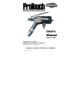
1
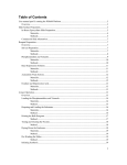
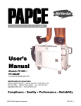
Automatic Spray
Equipment Cleaning
System
User’s
M anual
UG-45V
Smith Eastern Corporation
10630-S Riggs Hill Road • Jessup, Maryland 20794-9425 USA
301.497.7600 • 800.937.HVLP (4857) • Fax 301.497.7613
[email protected] • www.airverter.com
Compliance • Quality • Performance • Reliability
© 2001 Smith Eastern Corporation
AirVerter® Automatic Spray Equipment Cleaning System
DO NOT OPERATE WITHOUT PERSONAL SAFETY EQUIPMENT
AirVerter® Automatic Spray Equipment Cleaning System
Please Read This Owner’s Manual BEFORE
Using Your Automatic Spray Equipment Cleaning
System
DO NOT OPERATE THIS EQUIPMENT WITHOUT USING PROPER
PERSONAL SAFETY EQUIPMENT INCLUDING RESPIRATOR, GOGGLES
AND SAFETY CLOTHING. OBSERVE ALL PRECAUTIONS RELATED TO
SPRAYING.
WARNING
THIS EQUIPMENT IS OPERATED USING PRESSURIZED AIR. ALWAYS
DISCONNECT THE SYSTEM FROM AIR AND FLUID HOSES AND
DEPRESSURIZE SYSTEM PRIOR TO ANY MAINTENANCE OR
DISASSEMBLY PROCEDURE.
WARRANTY
Smith Eastern Corporation warrants to the Purchaser that the Automatic Spray Equipment
Cleaning System is free from defects in material or workmanship under normal use and service for
a period of twelve (12) months from the date of purchase. Should any failure appear during this
period, Smith Eastern shall, if given prompt written notice by the Purchaser, correct such
nonconformity by repair or replacement of the nonconforming part, F.O.B. Smith Eastern’s repair
facility. Repair parts are warranted for ninety (90) days from the date of shipment, but repairs or
replacements to original equipment shall not renew or extend the warranty period of such
equipment. Equipment and parts furnished by Smith Eastern but manufactured by others shall be
limited to the warranty offered by the manufacturer thereof.
Smith Eastern reserves the right to limit this warranty in cases of misuse or abuse. Any
modifications to equipment or recommended procedures will void the warranty.
The foregoing warranty is exclusive and in lieu of other warranties of quality or performance,
expressed, implied or statutory, including any warranties of merchantability or of fitness for a
particular purpose.
DO NOT OPERATE WITHOUT PERSONAL SAFETY EQUIPMENT
AirVerter® Automatic Spray Equipment Cleaning System
BEFORE USING
1. Carefully inspect the shipping carton for any
signs of transport damage. Damage to the
transport carton often indicates damage to
the unit inside. In case of damage call 1800-937-4857 for instructions.
2. Carefully remove the equipment from the
shipping carton
3. Check the equipment immediately and
carefully to insure that it is not damaged,
particularly the adjustable legs on the
bottom of the unit. Report any damage to
the carrier without delay to initiate claim
procedures. Smith Eastern Corporation is
not responsible for damage to the
equipment after it leaves our warehouse.
4. A Serial Number Label complying with
applicable Marking and Labeling System
Standards is permanently affixed to the
inside back of the base cabinet door. Vital
information, such as Serial Number, Model
Number, Air Supply Specifications, etc. is
clearly marked on the label.
5. Check to ensure you received the following
accessories:
a.
Operating Manual (1)
b.
Trigger Holding Clamp (2)
c.
Air Inlet Cap (2)
d.
Nozzle Adapter (1)
e.
Tapered Plug (1)
All items listed above are packaged in a sealed
clear plastic bag.
6. This manual is a very important document
for the safe and effective operation of this
equipment.
Carefully read this manual
before operation. Keep this manual close at
hand so that it is readily available as
required.
DO NOT OPERATE WITHOUT PERSONAL SAFETY EQUIPMENT
AirVerter® Automatic Spray Equipment Cleaning System
EQUIPMENT SET-UP
1. Position the unit in a well-ventilated area.
2. Select the installation position so that the
unit is not near sparks, open flame, or a
source of heat.
3. Set the Adjustable Legs to suit floor level
and solvent container height.
4. Connect Ground Wire firmly to the bare
surface of a grounded metal object.
5. The Air Inlet Fitting is located on the right
side of the unit. Connect the air supply
firmly to the Air Inlet Fitting (1/4" female
threads) and ensure there is no air leakage
at the connection.
6. The compressed air supply must be free of
water, dust, grease, and other foreign
material, and the air pressure must be 75-85
P.S.I.
Smith
Eastern
Corporation
recommends the use of an inline
moisture separator filter.
7. Maintenance
–
when
service
or
maintenance is required, be sure to
disconnect the air supply or release
pressure at source.
8. Open the door of the Base Cabinet.
9. Check to ensure the Drain Valve Handle
located under the Cleaning Tank is in the
closed (horizontal) position.
10. Prepare two 5-gallon pails full of clean and
good quality gun cleaner solvent and
remove spout caps.
11. Disconnect Quick Coupler of Siphon Pipe
Assembly from Drain Valve and bring it to
outside of Base Cabinet.
12. Bring Rinse Pump to outside of Base
Cabinet.
13. Fully insert Rinse Pump into the first solvent
pail.
14. Move the pail into the Base Cabinet on the
right hand side.
15. Assemble Taper Adapter (supplied in
Accessory Kit) onto Siphon Pipe Assembly.
16. Remove half of the solvent from the second
solvent pail. Note: This is required only for
the initial setup.
17. Insert Siphon Pump Assembly into second
solvent pail through top spout.
18. Place second solvent pail under the Drain
Valve and connect Quick Coupler of Siphon
Pipe Assembly to Male Connector.
19. Turn Handle of Drain Valve to Open
Position (vertical) and close cabinet door.
Efficient Use of Gun Cleaner
Always clean spray guns and other painting equipment after use while the paint is still wet. To
keep the spray gun cleaner operating efficiently, replace contaminated solvent and clean or
replace filters regularly. Dirty solvent will decrease the performance of the equipment.
OPERATING INSTRUCTIONS
1. Before cleaning, remove excess paint from
spray guns, cups, paint pots, and hoses.
2. Open the lid of the cleaning tank fully.
3. Always place paint pot upside down over
the center spray post and paint cups upside
down over the low spray jets that protrude
through the work screen.
4. Release air cap of spray gun two full turns
and lock trigger in open position with a
trigger lock spring.
5. Install spray gun onto appropriate cleaning
nozzle with gun facing corner jets.
6.
Guns can be washed with or without air cap
installed. The air cap can be stored inside
the cleaning cabinet.
7. The cleaning tank is not recommended for
the storage of spray guns.
8. Press the Air Flush Button for no more than
2-3 seconds. Excessive use of the air flush
will cause solvent loss through atomization.
9. Although the rinse function may be used
repeatedly, wait 30 seconds for the Rinse
Pump to fully recharge.
DO NOT OPERATE WITHOUT PERSONAL SAFETY EQUIPMENT
AirVerter® Automatic Spray Equipment Cleaning System
10. After the cleaning operation has been
completed, remove guns and paint cups
from the cabinet, and wipe dry.
DO NOT OPERATE WITHOUT PERSONAL SAFETY EQUIPMENT
AirVerter® Automatic Spray Equipment Cleaning System
Cleaning Spray Guns and Cups
1. Set the valve
(vertical).
handle
to
“equipment”
2. Any paint left in the gun, cup, or paint pot
should be emptied into a waste paint
container for proper disposal.
3. Lock trigger of paint gun in open position
with the trigger lock spring provided.
4. Open lid of cleaning tank and install adapter
nozzle onto taper nozzle.
5. Fit paint inlet of spray gun onto nozzle
adapter.
a.
The flexible nozzle adapter may be
used to clean a spray gun by fitting a
taper adapter into the paint inlet of
the flexible adapter.
b.
Paint cup of gravity or siphon type
sray gun may be cleaned by placing
it upside down over the taper nozzle
and spray jet.
6. Close the lid and turn Timer Knob clockwise
to start wash cycle. The automatic wash
cycle is complete in about 45 seconds.
7. Push Air Flush Button for about 3 seconds
to send air through inside passages of spray
gun and to inside of paint cup. This helps
flush out contaminated solvent.
8. Push Clean Rinse Button for about 5
seconds to rinse inside passages of spray
gun and paint cup with about 100cc of clean
solvent. The solvent is followed by a flow of
air for extra cleaning.
DO NOT OPERATE WITHOUT PERSONAL SAFETY EQUIPMENT
AirVerter® Automatic Spray Equipment Cleaning System
Cleaning Paint Feeder Hose
This equipment can clean a Paint Feeder Hose
up to 100 feet long. Inlet and outlet fittings are
¼" NPT female threads. If the hose to be
cleaned is fitted with a quick connector, you
should install matching Male and Female Quick
Connectors to the inlet and outlet fittings before
starting the hose cleaning operation.
1. Set the handle to
(horizontal) position.
“Hose”
cleaning
2. Connect one end of the hose to the outlet
fitting, located at the right side of the unit.
3. Connect the other end of the hose to the
inlet fitting, located at the upper front of the
tank.
4. Turn Timer Knob to start wash cycle. The
wash cycle stops automatically in about 45
seconds.
5. Make sure both ends of the hose are
connected firmly and that no solvent is
leaking at the connections.
6. Push the Air Flush Button for about 3
seconds to send air into the pot to flush out
contaminated solvent.
1. Press Clean Rinse Button for about 5-7
seconds to rinse the pot with about 100cc of
clean solvent. This is followed by a flow of
air for extra cleaning.
2. Disconnect the hose from the inlet and
outlet fittings.
DO NOT OPERATE WITHOUT PERSONAL SAFETY EQUIPMENT
AirVerter® Automatic Spray Equipment Cleaning System
UG-45V Illustrated Parts Breakdown
DO NOT OPERATE WITHOUT PERSONAL SAFETY EQUIPMENT
AirVerter® Automatic Spray Equipment Cleaning System
Automatic Spray Equipment Cleaning System Parts List
Part # Description
Part # Description
1
6
8
10
11
12
13
16
17
Lid assembly
Lid / Door Handle
Lid Switch Plate, Adjustable
Delivery Tubes
Nozzle Adapter
Spray Jet Assembly
Gun Cleaner Taper Nozzle
Mechanical Timer Control Knob
Air Rinse Control Knob
36
37
38
39
40
41
42
43
Hose Clamp (7mm)
Air Hose
Solvent Hose
Hose Clamp #4
Hose Clamp
Hose Barb, 3/8" x 1/8" NPT
Pump Clamp
Main Pump, Dual Seals
45
Rubber Cushion
19
20
22
23
24
25
27
29
30
31
32
33
34
35
Mechanical Timer Assembly
Air Rinse Valve Assembly
Adjustable Leveler Foot, Long
Stop Cock Valve Assembly
Quick Coupling Nipple (male)
Solvent Suction Pump Assembly
Door Assembly, Complete
Base Cabinet
Spray Gun Hanger Bar
Filter Pad (10 pack)
Flame Retardant Screen
Lid Opening Stop Arm
Stainless Steel Tank Assembly
Pump Mounting Bracket
46
Hose Barb ¼"
47
Hose Clamp
48
Exhaust Silencer Tube
49
Lid Switch Valve Assembly
50
Fume Exhaust Tube Assembly
51
Toggle Switch Air Valve
55
Valve Handle
56
Three-way Valve Assembly
57
Four-way Valve Assembly
58
Rinsing Pump Assembly
59
Tapered Plug Stopper
60
Elbow Fitting
61
Solvent Tube
DO NOT OPERATE WITHOUT PERSONAL SAFETY EQUIPMENT
AirVerter® Automatic Spray Equipment Cleaning System
WARNING
Disconnect all air and fluid hoses prior to performing any maintenance
operation.
Daily Maintenance
When the unit is not in use, drain solvent from
the cleaning tank into the solvent container.
Then close the drain valve. Keep spray gun
cleaner and surrounding area clean at all times.
Always
inspect
the
solvent
storage
compartment of the unit to ensure there is no
leakage from the solvent containers. Open the
drain to the solvent container before operating.
Automatic Spray Equipment Cleaning System
Troubleshooting Guide
Trouble
Probable Cause
Remedy
1. Low air pressure
1. Increase air pressure to 75-85 P.S.I.
2. Filter screen inside air inlet
fitting clogged with debris
2. Disconnect air supply and clean the filter
screen
3. Blocked spray jet nozzles
3. Remove and clean
4. Filter pad too dirty
4. Clean or replace filter pad
5. Drain valve is closed and
solvent is not draining
5. Turn drain valve to open (vertical)
position
6. Dirty solvent
6. Replace solvent
7. Pump defective
7. Repair/replace pump
8. Poppet in combination valve
is stuck in closed position
8. Repair/replace combination valve
1. Trigger Lock Spring is not
properly installed or paint valve
of spray gun is closed
1.
2. Spray gun not properly
installed onto cleaning nozzle
2. Ensure paint gun is firmly installed and
not too loose on cleaning nozzle. Use
suitable nozzle adapter as required
1. Main seals of pump worn
1. Repair or replace pump
2. Air pressure too high
2. Decrease air pressure to 75-85 P.S.I.
Timer spins back
to original
position
1. Timer defective
1. Replace Timer
Timer not clicking
1. Timer defective
1. Replace Timer
1. Rinse Pump defective
1. Replace Rinse Pump
2. Clean Rinse Air Valve is
defective
2. Replace Clean Rinse Air Valve
Little or no
washing action
Inside of spray
gun is not
cleaned
Solvent leaking
around tank lid
Clean rinse does
not work
Install Trigger Lock Spring/ ensure paint
valve is open
DO NOT OPERATE WITHOUT PERSONAL SAFETY EQUIPMENT
AirVerter® Automatic Spray Equipment Cleaning System
Trouble
Probable Cause
Dirty solvent
moving into clean
solvent pail
Solvent leaking
from air rinse
valve
Remedy
1. Combination Valve is
defective and leaking
1. Repair/replace Combination Valve
1. One-way check valve in the
Combination Valve is
defective
1. Repair/replace Combination Valve
2. Repair/replace One-way Check Valve
2. One-way Check Valve in the
Check Valve Assembly is
defective
Diagnostic Procedures
When the pump does not work and there is no
obvious defect such as excessive air leaking
out of the exhaust pipe at the top of the pump
try the following:
1. Disconnect the air hose from the pump Air
Inlet (cut close to pump if necessary). Turn
the timer “On”.
2. If air blows out of air hose leading from the
timer when the timer is turned on and stops
when timer is turned off, the timer is
working, but the pump may be defective.
3. Using a hand blowgun, apply air pressure to
the Air Inlet of the pump. If the pump works
normally, there may be a kink or blockage in
the air line.
4. When the timer is working normally and the
solvent pail is full, but no solvent comes out
of the spray jets, either the pump is
defective or the suction line before the
pump is blocked.
5. Disconnect Suction Pump Assembly from
the bottom of the tank. Check the suction
vacuum of the pump by testing the suction
inlet of Suction Pipe Assembly for a
vacuum. If no vacuum is present the pump
is defective and must be repaired/replaced.
6. If strong vacuum is present, the pump is
operating correctly and the problem may be
due to a blockage in the suction hose or
suction pipe. Disconnect the suction hose
(black) at the suction pipe and test for
vacuum by closing the end of the suction
hose.
7. If no vacuum is present, the suction hose is
blocked and must be cleaned or replaced.
8. If strong vacuum is present, the blockage is
probably in the suction pipe assembly.
Remove the blockage by blowing air into air
barb of the suction pipe assembly.
DO NOT OPERATE WITHOUT PERSONAL SAFETY EQUIPMENT