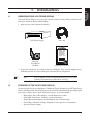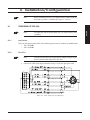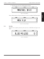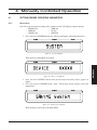
1
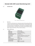
Model 3410 Torque Display User’s Manual Purchase Record Please record all model numbers and serial numbers of your Magtrol equipment, along with the general purchase information. The model number and serial number can be found on either a silver identification plate or white label affixed to each unit. Refer to these numbers whenever you communicate with a Magtrol representative about this equipment. Model Number: _____________________________ Serial Number: _____________________________ Purchase Date: _____________________________ Purchased From: _____________________________ While every precaution has been exercised in the compilation of this document to ensure the accuracy of its contents, Magtrol, Inc. assumes no responsibility for errors or omissions. Additionally, no liability is assumed for any damages that may result from the use of the information contained within this publication. COPYRIGHT Copyright ©2005–2012 Magtrol, Inc. All rights reserved. Copying or reproduction of all or any part of the contents of this manual without the express permission of Magtrol is strictly prohibited. TRADEMARKS LabVIEW™ is a trademark of National Instruments Corporation. National Instruments™ is a trademark of National Instruments Corporation. Windows® is a registered trademark of Microsoft Corporation. Preliminary Manual, revision I – October 2012 Safety Precautions 1. Make sure that all Magtrol Torque Transducers and electronic products are earth-grounded, to ensure personal safety and proper operation. 2. Make sure that torque transducers and motors under test are equipped with appropriate safety guards. i Revisions To This Manual The contents of this manual are subject to change without prior notice. Should revisions be necessary, updates to all Magtrol User’s Manuals can be found at Magtrol’s web site at www.magtrol.com/support/manuals.htm. Please compare the date of this manual with the revision date on the web site, then refer to the manual’s Table of Revisions for any changes/updates that have been made since this edition. REVISION DATE Prelimimary Manual, revision I – October 2012 TABLE OF REVISIONS Date 10/11/12 10/02/12 09/17/12 09/21/10 05/14/10 02/10/09 12/18/08 12/18/08 08/24/07 08/24/07 08/24/07 07/20/06 07/20/06 Edition Preliminary manual, rev. I Preliminary manual, rev. H Preliminary manual, rev. G Preliminary manual, rev. F Preliminary manual, rev. E Preliminary manual, rev. D Preliminary manual, rev. C Preliminary manual, rev. C Preliminary manual, rev. B Preliminary manual, rev. B Preliminary manual, rev. B Preliminary manual, rev. A Preliminary manual, rev. A Change Section(s) The OV and OS command added to section 5.2.1. The CALS and 5.2.1, 5.3 FREQ# command added to section 5.3 Code UD = 6 added for TF 3xx series Torque Flange Sensors. 5.2.2, 5.2.2.1 Calibration procedure updated. 6.3, 6.3.1, 6.3.2, 6.3.3 TF models 205 and 209 added 5.2.2.1 TF models 205 and 209 added 4.1.2 Pin 2 of RS-232C connector changed from “RX” to “TX”. Pin 3 of RS-232C connector changed from “TX” to “RX”. 2.2.1, 5.1 Deca-Newton meters (daN·m) added to torque units selection 4.1.3, 5.2.2 TF 220 added to model selection 4.1.2, 5.2.2.1 *IDN? command added 5.2.1 OD command data string changed 5.2.1 TM 301 and 302 added to model selection/codes 4.1.2, 5.2.2.1 Speed Output BNC changed to 3.3 VHC pulse (buffered from 1.3 transducer) To accommodate Magtrol Dial Weight Dynamometers: Pin 7 of TRANSDUCER connector changed from “N/C” to “5 V OUT”. 2.2.1 Pin 8 of TRANSDUCER connector changed from “N/C” to “5 V COM”. ii Table of Contents SAFETY PRECAUTIONS..........................................................................................................................I REVISIONS TO THIS MANUAL................................................................................................................II REVISION DATE..................................................................................................................................................................II TABLE OF REVISIONS.......................................................................................................................................................II TABLE OF CONTENTS...........................................................................................................................III PREFACE................................................................................................................................................ VI PURPOSE OF THIS MANUAL......................................................................................................................................... VI WHO SHOULD USE THIS MANUAL.............................................................................................................................. VI MANUAL ORGANIZATION............................................................................................................................................. VI CONVENTIONS USED IN THIS MANUAL...................................................................................................................VII 1. INTRODUCTION.................................................................................................................................1 1.1 UNPACKING YOUR 3410 TORQUE DISPLAY.......................................................................................................... 1 1.2 FEATURES OF THE 3410 TORQUE DISPLAY.......................................................................................................... 1 1.3 DATA SHEET................................................................................................................................................................. 2 2. CONTROLS..........................................................................................................................................4 2.1 FRONT PANEL.............................................................................................................................................................. 4 2.2 REAR PANEL................................................................................................................................................................ 5 2.2.1 REAR PANEL INPUTS AND OUTPUTS...................................................................................................... 5 2.2.2 REAR PANEL CONTROLS AND BUTTONS............................................................................................... 6 3. INSTALLATION/CONFIGURATION.....................................................................................................7 3.1 POWERING UP THE 3410........................................................................................................................................... 7 3.1.1 LINE VOLTAGE.............................................................................................................................................. 7 3.1.2 SELF-TEST..................................................................................................................................................... 7 3.1.3 MAIN MENU.................................................................................................................................................. 8 4. MANUALLY CONTROLLED OPERATION..........................................................................................9 4.1 SETTING DESIRED OPERATING PARAMETERS................................................................................................... 9 4.1.1 DEVICE SETUP.............................................................................................................................................. 9 4.1.2 MODEL SELECTION................................................................................................................................... 10 4.1.3 TORQUE UNITS SETUP.............................................................................................................................. 11 4.1.4 POWER UNITS SETUP................................................................................................................................ 11 4.1.5 CONTRAST SETUP..................................................................................................................................... 12 4.1.6 SYSTEM SETUP CHECK............................................................................................................................ 12 4.1.7 TARE FUNCTION........................................................................................................................................ 13 4.1.8 BITE FUNCTION.......................................................................................................................................... 13 5. COMPUTER CONTROLLED OPERATION.......................................................................................14 5.1 ABOUT THE RS-232 INTERFACE............................................................................................................................ 14 5.1.1 CONNECTION.............................................................................................................................................. 14 5.1.2 COMMUNICATION PARAMETERS.......................................................................................................... 14 5.2 3410 COMMAND SET................................................................................................................................................ 15 5.2.1 COMMUNICATION COMMANDS............................................................................................................. 15 iii Table of Contents 5.2.2 5.3 Magtrol Model 3410 Torque Display SETUP COMMANDS................................................................................................................................... 15 CALIBRATION COMMANDS.................................................................................................................... 17 6. CALIBRATION...................................................................................................................................18 6.1 CLOSED-BOX CALIBRATION................................................................................................................................. 18 6.2 CALIBRATION SCHEDULE...................................................................................................................................... 18 6.3 BASIC CALIBRATION PROCESS............................................................................................................................. 18 6.3.1 INITIAL CALIBRATION PROCEDURE..................................................................................................... 18 6.3.2 TORQUE OFFSET AND GAIN.................................................................................................................... 18 6.3.3 FREQUENCY GAIN..................................................................................................................................... 19 7. TROUBLESHOOTING........................................................................................................................20 APPENDIX A: SCHEMATICS.................................................................................................................21 A.178P205 BOARD........................................................................................................................................................... 21 GLOSSARY............................................................................................................................................22 INDEX......................................................................................................................................................23 SERVICE INFORMATION.......................................................................................................................24 RETURNING MAGTROL EQUIPMENT FOR REPAIR AND/OR CALIBRATION...................................................... 24 RETURNING EQUIPMENT TO MAGTROL, INC. (UNITED STATES)................................................................. 24 RETURNING EQUIPMENT TO MAGTROL SA (SWITZERLAND)...................................................................... 24 iv Table of Contents Magtrol Model 3410 Torque Display TABLE OF FIGURES 2. CONTROLS Figure 2–1 Figure 2–2 Figure 2–3 Figure 2–4 Front Panel................................................................................................................................................4 Rear Panel.................................................................................................................................................5 Transducer Connector...............................................................................................................................5 RS-232C Interface.....................................................................................................................................5 3. INSTALLATION/CONFIGURATION Figure 3–1 Figure 3–2 Figure 3–3 Figure 3–4 Cable and Connection Diagrams..............................................................................................................7 Title Display..............................................................................................................................................8 Revision Display........................................................................................................................................8 Main Menu................................................................................................................................................8 4. MANUALLY CONTROLLED OPERATION Figure 4–1 Figure 4–2 Figure 4–3 Figure 4–4 Figure 4–5 Figure 4–6 Figure 4–7 Figure 4–8 Figure 4–9 System Display..........................................................................................................................................9 Device Setup Menu....................................................................................................................................9 Saving System Display...............................................................................................................................9 Model Selection Menu.............................................................................................................................10 Torque Units Setup Menu........................................................................................................................11 Power Units Setup Menu.........................................................................................................................11 Contrast Setup Menu...............................................................................................................................12 System Check Display Example..............................................................................................................12 BITE Display...........................................................................................................................................13 5. COMPUTER CONTROLLED OPERATION Figure 5–1 RS-232 Interface......................................................................................................................................14 Figure 5–2 Cable Connection....................................................................................................................................14 v Preface PURPOSE OF THIS MANUAL This manual contains all the information required for the installation and general use of the Model 3410 Torque Display. To achieve maximum capability and ensure proper use of the instrument, please read this manual in its entirety before operating. Keep the manual in a safe place for quick reference whenever a question should arise. WHO SHOULD USE THIS MANUAL This manual is intended for bench test operators who are going to use the 3410 Torque Display in conjunction with any Magtrol TM In-Line Torque Transducer and TF Torque Flange Sesnor. MANUAL ORGANIZATION This section gives an overview of the structure of the manual and the information contained within it. Some information has been deliberately repeated in different sections of the document to minimize cross-referencing and to facilitate understanding through reiteration. The structure of the manual is as follows: Chapter 1: INTRODUCTION - Contains the technical data sheet for the 3410 Torque Transducer Display, which describes the unit and provides its mechanical and electrical characteristics. Chapter 2: CONTROLS - Description of the elements located on the front and rear panels of the unit. Chapter 3: INSTALLATION/CONFIGURATION - Provides information needed for setup of the 3410. Chapter 4: MANUALLY CONTROLLED OPERATION - How to run a test when the 3410 is used as a stand-alone unit. Chapter 5: COMPUTER CONTROLLED OPERATION - How to run a test when the 3410 is used with a personal computer. Includes information on serial (RS-232) interface and command set. Chapter 6: CALIBRATION - Provides recommended calibration schedules along with stepby-step instructions for the calibration procedure. Chapter 7: TROUBLESHOOTING - Solutions to common problems encountered during setup and testing. Appendix A: SCHEMATICS - For the analog section. Glossary: List of abbreviations and terms used in this manual, along with their definitions. vi Preface Magtrol Model 3410 Torque Display CONVENTIONS USED IN THIS MANUAL The following symbols and type styles may be used in this manual to highlight certain parts of the text: Note: This is intended to draw the operator’s attention to complementary information or advice relating to the subject being treated. It introduces information enabling the correct and optimal functioning of the product to be obtained. Caution:This is used to draw the operator’s attention to information, directives, procedures, etc. which, if ignored, may result in damage being caused to the material being used. The associated text describes the necessary precautions to take and the consequences that may arise if the precautions are ignored. WARNING! THIS INTRODUCES DIRECTIVES, PROCEDURES, PRECAUTIONARY MEASURES, ETC. WHICH MUST BE EXECUTED OR FOLLOWED WITH THE UTMOST CARE AND ATTENTION, OTHERWISE THE PERSONAL SAFETY OF THE OPERATOR OR THIRD PARTY MAY BE PUT AT RISK. THE READER MUST ABSOLUTELY TAKE NOTE OF THE ACCOMPANYING TEXT, AND ACT UPON IT, BEFORE PROCEEDING FURTHER. vii 1.1 Introduction UNPACKING YOUR 3410 TORQUE DISPLAY Your 3410 Torque Display was packaged in reusable, shock resistant packing material that will protect the instrument during normal handling. 1. Make sure the carton contains the following: POWER TORQUE SPEED MODEL 3410 TORQUE DISPLAY Line cord 3410 Torque Display Magtrol User Manual CD-Rom Calibration Certificate 2. Inspect the contents for any evidence of damage in shipping. In the event of shipping damage, immediately notify the carrier and Magtrol’s Customer Service Department. 1.2 Note: Save all shipping cartons and packaging material for reuse when returning the instrument for calibration or servicing. FEATURES OF THE 3410 TORQUE DISPLAY Designed specifically for use with Magtrol’s TM In-Line Torque Transducers and TF Torque Flange Sensors, the Model 3410 Torque Display powers the transducer and utilizes high-speed digital signal processing to display torque, speed and mechanical power. Its features include: • High Quality, Easy-to-Read Display: Vacuum fluorescent readout. • Isolated RS-232 Interface: Eliminates system ground loops. • Torque Measurement Options: Standard English, metric and SI settings. • Closed-Box Calibration of Torque: Eliminates need to open box for adjustments. • Speed and Torque Outputs 1 GENERAL INFORMATION 1. Chapter 1 – Introduction M AGTROL DATA SHEET 3410 Data Sheet Model 3410 Torque Display Features • • • • • • • • • • ForusewithallMagtrolTM/TMHS/TMBIn-Line TorqueTransducersandTFTorqueFlangeSensors HighQuality,Easy-to-ReadVacuumFluorescent Readout:Displaystorque,speedandpower AdjustableEnglish,MetricandSITorqueUnits IsolatedRS-232Interface TorqueandSpeedOutputs BITE:Built-InTestEquipment OverloadIndication TareFunction ClosedBoxCalibration IncludesMagtrolTorque1.0Software DesCriPtion torque 1.0 soFtware Magtrol’sModel3410TorqueDisplayisdesignedforusewith allTM,TMHS,TMBandTFTorqueTransducers.Thiseasyto-usedevicepowersthetransducerandutilizeshighspeed DigitalSignalProcessing(DSP)todisplaytorque,speedand mechanicalpower.Itincludesatarefunctiontohelpoffsetany slightresidualscausedbycouplingsorsuspendedloads.The 3410mayalsobeusedwithsensorsrequiring24VDCpower (400mAmax.)andhave±5VDCtorqueoutput(±10VDC max.)and3.3VHCspeedoutput. Magtrol’sTorque 1.0 Software is a user-friendlyWindows® executableprogram,usedtoautomaticallycollecttorque,speed andmechanicalpowerdata.Thedatacanbeprinted,displayed graphicallyorquicklysavedasaMicrosoft®Excelspreadsheet. StandardfeaturesofTorque1.0include: • MeasuredParametervs.Time • AdjustableSamplingRates • PolynomialCurveFitting • PeakTorqueCapture • DirectionofRotation • Multi-AxesGraphing • OptionalUSBInterface:forreadingupto4thermocouples system ConFiguration TF Torque Flange Sensor Receiver PC Torque 1.0 Software SPEED – OR – TARE SELECT SYSTEM TORQUE RS-232C TRANSDUCER MAGTROL MODEL 3410 TORQUE DISPLAY TM, TMHS or TMB Series In-Line Torque Transducer 2 www.magtrol.com GENERAL INFORMATION 1.3 Magtrol Model 3410 Torque Display Chapter 1 – Introduction Magtrol Model 3410 Torque Display GENERAL INFORMATION Specifications 3410 MEASUREMENT CHARACTERISTICS Maximum Speed / 99,999 rpm / 99,999 Hz Input Frequency Speed: 0.01% of reading from Accuracy 5 rpm to 100,000 rpm Torque: 0.01% of range (± 5 V) ELECTRICAL CHARACTERISTICS Fuses (5 × 20 mm) IEC 500 mA 250 V T Power Requirements 30 VA Voltage Requirements 120/240 V 60/50 Hz INPUTS AND OUTPUTS Maximum Torque Input ±10 V DC Torque Output BNC ±10 V DC (direct from transducer) Speed Output BNC 3.3 V HC pulse (buffered from transducer) ENVIRONMENT Operating Temperature 5 ºC to 40 ºC Relative Humidity < 80% Temperature Coefficient 0.001% (5 ºC to 50 ºC) of FS/ºC DIMENSIONS Width 9.88 in 251 mm Height 2.80 in 71 mm Depth 7.49 in 190 mm Weight 2.85 lb 1.28 kg Displays Torque, Speed and Mechanical Power Values Front Panel RS-232C Connection Isolated RS-232 Interface for Connection to PC Select Button Display Current Setup or Make System Selections Tare Button Tare Function Torque Output Speed Output rear Panel Transducer connection - System Button For Use With Any Magtrol TM, TMHS, TMB or TF Torque Transducer Set Desired Model, Torque and Power Units aCCessories Description TM / TMHS / TMB In-Line Torque Transducer Connector Cable, 5 m TM / TMHS / TMB In-Line Torque Transducer Connector Cable, 10 m TM / TMHS / TMB In-Line Torque Transducer Connector Cable, 20m TF Flange Torque Transducer Connector Cable, 5 m TF Flange Torque Transducer Connector Cable, 10 m TF Flange Torque Transducer Connector Cable, 20m Model/Part # ER 113-01 ER 113-02 ER 113-03 ER 116-01 ER 116-02 ER 116-03 Due to the continual development of our products, we reserve the right to modify specifications without forewarning. magtrol inC 70 Gardenville Parkway Buffalo, New York 14224 USA Phone: +1 716 668 5555 Fax: +1 716 668 8705 E-mail: [email protected] magtrol sa Centre technologique Montena 3 1728 Rossens / Fribourg, Switzerland Phone: +41 (0)26 407 3000 Fax: +41 (0)26 407 3001 E-mail: [email protected] Subsidiaries in: Great Britain Germany • France China • India Worldwide Network of Sales Agents 3410-US 07/08 www.magtrol.com 2.1 FRONT PANEL The front panel contains a Vacuum Fluorescent Display (VFD) that provides information about the control functions and torque transduce. POWER TORQUE SPEED MODEL 3410 TORQUE DISPLAY Figure 2–1 Front Panel The displays from left to right are: • POWER • TORQUE • SPEED • Overload Indicator: If the inputs exceed the range of the instrument, “-OL-” will appear in the TORQUE or SPEED portion of the display. Once the condition has cleared, the unit will automatically return to the main menu. 4 GENERAL INFORMATION 2. Controls Chapter 2 – Controls Magtrol Model 3410 Torque Display REAR PANEL The rear panel provides connectors and receptacles for connecting to appropriate equipment along with a power switch and 3 control buttons. TORQUE TRANSDUCER MAGTROL 2.2.1 SPEED TARE RS-232C SELECT SYSTEM 16VA 50/60Hz 85-264VAC INPUT FUSE: 500 mA 250V T 5×20mm Figure 2–2 Rear Panel Rear Panel Inputs and Outputs TRANSDUCER Connect transducer signal cable here. 7 6 5 4 3 2 1 14 13 12 11 10 9 8 8. 9. 10. 11. 12. 13. 14. 1. N/C 2. N/C 3. +24 VDC 4. +24 VDC COM 5. +24 VDC COM 6. N/C 7. 5 V OUT 5 V COM ROTATIONAL DIRECTION SPEED N/C BITE TORQUE COMMON TORQUE SIGNAL Figure 2–3 Transducer Connector RS-232C Isolated RS-232 Connector 5 4 9 3 8 1. 2. TX 3. RX 4. 5. GND 2 7 1 6 6. 7. 8. 9. Figure 2–4 RS-232C Interface POWER Attach IEC approved power cord here. TORQUE Torque Output: Connect to data acquisition system here. SPEED Speed Ouput: Connect to data acquisition system here. 5 GENERAL INFORMATION 2.2 Chapter 2 – Controls Rear Panel Controls and Buttons GENERAL INFORMATION 2.2.2 Magtrol Model 3410 Torque Display The rear panel controls and buttons, from left to right, are: • Power switch • System button • Select button • Tare button The following table provides a quick reference on how to use each button. For more detailed information refer to Chapter 4 – Manually Controlled Operation. Button POWER SYSTEM SELECT TARE To Use Press I to turn power ON. Press O to turn power OFF. Function Turns power ON or OFF. Enables setup of torque measuring device, transducer model, torque units, power units and display contrast settings. During SYSTEM setup, scrolls through During SYSTEM setup, press available torque measuring device, transducer model, torque unit, power unit and display and release. During normal operation, press contrast setting options. and hold button. During normal operation, displays current setup. Sets the current A/D reading as the offset value Press. during calculations. Press. 6 3. Installation/Configuration 3.1 Before installing the 3410, you should become familiar with the front and rear panels, as outlined in Chapter 2–Controls. POWERING UP THE 3410 Note: To reduce the risk of electric shock, the case of the 3410 is earth grounded. Line Voltage The 3410 will operate with either of the following power sources without any modifications: • 120 V 50/60 Hz • 240 V 50/60 Hz 3.1.2 Self-Test Note: To make sure that the 3410 is operational, a Magtrol torque sensor must be installed and connected to the 3410. 1. Connect the 3410 to the torque transducer using a 14-pin to 6-pin signal cable. Figure 3–1 Cable and Connection Diagrams 7 SETUP 3.1.1 Note: Chapter 3 – Installation/Configuration Magtrol Model 3410 Torque Display 2. Turn on the power to the 3410. The Title Display will appea. POWER TORQUE SPEED Figure 3–2 Title Display POWER TORQUE SPEED Figure 3–3 Revision Display 3.1.3 Main Menu When the 3410 is completely powered up and ready for use, the Main Menu will appear on the dispay. POWER TORQUE Figure 3–4 Main Menu 8 SPEED SETUP Then an additional display will appear indicating the version of your Magtrol 3410 Torque Displa. 4. Manually Controlled Operation 4.1 SETTING DESIRED OPERATING PARAMETERS 4.1.1 Device Setup Selects the type of torque measuring device connected to the 3410 Display. Options include: • TM(HS) 200 • TMB 300 • TMB 200 • TF 200 • TM(HS) 300 • SPECIAL 1. Press and release SYSTEM button once. The System Display will flash momentarily. POWER TORQUE SPEED Figure 4–1 System Display Then the Device Setup Menu will appear. POWER TORQUE SPEED OPERATION Figure 4–2 Device Setup Menu 2. Press and release SELECT button until desired torque measuring device appears in display. 3. Press and release SYSTEM button 5 times. The Saving System Display will flash momentarily. POWER TORQUE Figure 4–3 Saving System Display Then the display will return to the Main Menu. 9 SPEED Chapter 4 – Manually Controlled Operation 4.1.2 Magtrol Model 3410 Torque Display Model Selection Selects the specific torque transducer model. Options include: TM / TMHS 200 Series ------TM(HS) 204 TM(HS) 205 TM(HS) 206 TMB 200 Series ------TMB 204 TMB 205 TMB 206 TM / TMHS 300 Series TM 301 TM 302 TM(HS) 303 TM(HS) 304 TM(HS) 305 TM(HS) 306 TMB 300 Series ----TMB 303 TMB 304 TMB 305 TMB 306 TF 200 Series --------TF 205 --- TM(HS) 207 TM(HS) 208 TM(HS) 209 TM(HS) 210 TM(HS) 211 TM(HS) 212 TM(HS) 213 TM(HS) 214 TM(HS) 215 TM(HS) 216 TM(HS) 217 ------- TMB 207 TMB 208 TMB 209 TMB 210 TMB 211 TMB 212 TMB 213 --------------- TM(HS) 307 TM(HS) 308 TM(HS) 309 TM(HS) 310 TM(HS) 311 TM(HS) 312 TM(HS) 313 TM(HS) 314 TM(HS) 315 TM(HS) 316 TM(HS) 317 ------- TMB 307 TMB 308 TMB 309 TMB 310 TMB 311 TMB 312 TMB 313 --------------- ----TF 209 TF 210 TF 211 TF 212 TF 213 TF 214 TF 215 TF 216 TF 217 TF 218 TF 219 TF 220 1. Press and release SYSTEM button 2 times. The Model Selection Menu will appear. TORQUE SPEED Figure 4–4 Model Selection Menu 2. Press and release SELECT button until desired torque transducer model appears in display. 3. Press and release SYSTEM button 4 times. The Saving System Display will flash momentarily and the unit will automatically return to the Main Menu. 10 OPERATION POWER Chapter 4 – Manually Controlled Operation Magtrol Model 3410 Torque Display 4.1.3 Torque Units Setup Selects the desired unit of measure that corresponds with the values displayed. Options include: • oz·in • mN·m • oz·ft • cN·m • lb·in • N·m • lb·ft • daN·m • g·cm • kN·m • kg·cm 1. Press and release SYSTEM button 3 times. The Torque Units Setup Menu will appear. POWER TORQUE SPEED Figure 4–5 Torque Units Setup Menu 2. Press and release SELECT button until the desired unit of measure is displayed. 3 Press and release SYSTEM button 3 times. The Saving System Display will flash momentarily and the unit will automatically return to the Main Menu. 4.1.4 Power Units Setup POWER TORQUE SPEED Figure 4–6 Power Units Setup Menu 2. Press and release SELECT button until the desired unit of power is displayed. 3. Press and release SYSTEM button 2 times. The Saving System Display will flash momentarily and the unit will automatically return to the Main Menu. 11 OPERATION Selects the desired unit of power that corresponds with the values displayed. Options include: • watts • kW • hp 1. Press and release SYSTEM button 4 times. The Power Units Setup Menu will appear. Chapter 4 – Manually Controlled Operation 4.1.5 Magtrol Model 3410 Torque Display Contrast Setup The 3410 is shipped with the Contrast programmed to the lowest setting in order to prolong display life. If it is necessary to increase the Contrast for improved readability, execute the following steps: 1. Press and release SYSTEM button 5 times. The display appears as follows: POWER TORQUE SPEED Figure 4–7 Contrast Setup Menu 2. Press and release SELECT button until desired brightness is reached (select from a range of 1 to 3). 3. Press and release SYSTEM button once. The Saving System Display will flash momentarily and the unit will automatically return to the Main Menu. 4.1.6 System Setup Check 1. To check and make sure that all parameters have been set properly, press and hold SELECT button. Example: POWER TORQUE SPEED Figure 4–8 System Check Display Example 2. When the SELECT button has been released, the unit will automatically return to the Main Menu. 12 OPERATION When testing a TM 314 (which has a 60-bit encoder), with power units expressed in watts and torque units expressed in oz.ft, the System Check Display will appear as follows: Chapter 4 – Manually Controlled Operation Magtrol Model 3410 Torque Display 4.1.7 Tare Function The calibrated offset of the 3410 may be changed using the tare function. To set: 1. Press TARE button. 2. Display will flash “TARE” and the unit will take the current value of the torque input and make it the new zero. 4.1.8 Note: In order to reset the tare value, the power to the unit must be turned OFF. BITE Function Built-In Test Equipment (BITE) has been programmed into the 3410 in order to test the system and make sure all devices are connected and running properly. When the BITE function is activated the software will turn on an NPN transistor internal to the 3410 that is in an open collector configuration. This output, or collector, is found on pin 12 of the 14-pin connector on the back of the unit. This signal is routed to the transducer and will activate internal circuitry to output a test signal. In the case of a TM series transducer, the output will be 5 volts (full scale) in addition to any offset value. As for the TF series, the output will be about 4 volts (about 80% of full scale) in addition to any offset value. To activate: 1. Press SELECT and TARE buttons simultaneously. 2. The display will flash “BITE”, then provide the full-scale voltage at the input of the unit. POWER TORQUE SPEED 3. After 5 seconds, the display automatically returns to the Main Menu. 13 OPERATION Figure 4–9 BITE Display 5. Computer Controlled Operation The 3410 Torque Display can be used with a personal computer for standard or custom torque and encoder setups. Using the 3410 with a computer enables the unit to perform at its full capacity. 5.1 ABOUT THE RS-232 INTERFACE The 3410 is equipped with an Isolated RS-232 (serial) interface that communicates with the host computer through a DB-9 interface connector. The connector pin-out consists of 2-TX, 3-RX and 5-GND. 5 4 9 3 8 2 7 1 6 1. 2. TX 3. RX 4. 5. GND 6. 7. 8. 9. N/C Figure 5–1 RS-232 Interface 5.1.1 Connection 3410 PC TX RX GND DIGITAL GROUND N/C 1. 2. 3. 4. 5. 6. 7. 8. 9. 1. 2. 3. 4. 5. 6. 7. 8. 9. STRAIGHT THROUGH CABLE CONNECTION (PIN TO PIN) Figure 5–2 Cable Connection 5.1.2 Communication Parameters • Default Baud Rate - 115200 • No parity • 8 data bits • 1 stop bit 14 DCD (DATA CARRIER DETECT) RX (RECEIVE DATA) TX (TRANSMIT DATA) DTR (DATA TERMINAL READY) GND (SIGNAL GROUND) DSR (DATA SET READY) RTS (REQUEST TO SEND) CTS (CLEAR TO SEND) RI (RING INDICATOR) OPERATION The RS-232 connection includes null modem wiring internal to the unit. To install, use a straight through pin-to-pin connector cable, which can be purchased from you local electronics store. Chapter 5 – Computer Controlled Operation Magtrol Model 3410 Torque Display 5.2 3410 COMMAND SET When entering a command code: 1. Type all characters in uppercase ASCII format. 2. End all commands with a CR-LF (hex 0D-0A). 3. Do not string multiple commands together in one line. The character # represents a floating-point numerical value following the command. Leading zeroes are not required. 5.2.1 Note: If a command is not recognized, a COMMAND ERROR CR-LF string return will occur accompanied by a beep. Communication Commands Command Code *IDN? Explanation Returns Magtrol identification and software revision. OD Prompts to return speedtorque-direction data string. OV Reads voltage applied to A/D channel in mV. OS Read speed value with more accuracy. --Output Data prompt to return data string with this format: SxxxxxTxxxxxRcrlf or SxxxxxTxxxxxLcrlf R or L is the shaft direction indicator, as viewed looking at the dynamometer shaft where: R = right; clockwise (CW) L = left; counterclockwise (CCW) The speed will equal the displayed value and the torque will be in the same units as displayed on the front panel. Output Data prompt to return data string with this format: XXXXXX.XXX Output Data prompt to return data string with this format: XXXXXX.XXXX Setup Commands Command Code Function Explanation BITE Activates built-in test function. M1 Enables rear panel controls. 15 The display will flash “BITE”, then provide the full-scale voltage at the input of the unit. After 5 seconds, the display automatically returns to the Main Menu. Use this command to enable rear panel control of most functions. OPERATION 5.2.2 Function Chapter 5 – Computer Controlled Operation Command Code Magtrol Model 3410 Torque Display Function Explanation Locks out rear panel controls. TR TS Resets Tare. Sets Tare. UD# Sets attached device. UE# Sets encoder units to # when device = SPECIAL (UD5). UI# Selects model. UR# Sets display torque units to #. UT# Sets torque scale to # when device = SPECIAL (UD5). SAVE Saves setup. 16 OPERATION MØ Use this command to lock out the rear panel controls, so that the Torque Display settings can be changed only by using the computer with RS-232 interface. Resets tare to 0 (zero). Reads current torque and uses as tare value. Values for # are: 0 = TM(HS) 2XX 1 = TMB 2XX 2 = TM(HS) 3XX 3 = TMB 3XX 4 = TF 2XX 5 = SPECIAL 6 = TF 3XX # = 1 to 6000 Programmed value # is not saved at power down. For measurments to be accurate, the correct transducer model must be specified. Note: Refer to table in Section 5.2.2.1 for list of models and corresponding values. Programmed value # is not saved at power down. Values for # are: 0 = oz·in 6 = mN·m 1 = oz·ft 7 = cN·m 2 = lb·in 8 = N·m 3 = lb·ft 9 = kN·m 4 = g·cm 10 = daN·m 5 = kg·cm Torque unit conversion defaults to 0 (oz·in) if out of range. Programmed value # is not saved at power down. # = 0 to 100,000 Programmed value # is not saved at power down. Saves values programmed via serial port. Chapter 5 – Computer Controlled Operation Magtrol Model 3410 Torque Display 5.2.2.1 Transducer Model Codes UI Value for # 0 1 2 3 4 5 6 7 8 9 10 11 12 13 14 15 16 17 5.3 UD = 2 UD = 0 UD = 1 TM(HS) 204 TM(HS) 205 TM(HS) 206 TM(HS) 207 TM(HS) 208 TM(HS) 209 TM(HS) 210 TM(HS) 211 TM(HS) 212 TM(HS) 213 TM(HS) 214 TM(HS) 215 TM(HS) 216 TM(HS) 217 N/A N/A N/A N/A TMB 204 TMB 205 TMB 206 TMB 207 TMB 208 TMB 209 TMB 210 TMB 211 TMB 212 TMB 213 N/A N/A N/A N/A N/A N/A N/A N/A REV 1.2 REV 1.3 TM(HS) 303 TM(HS) 304 TM(HS) 305 TM(HS) 306 TM(HS) 307 TM(HS) 308 TM(HS) 309 TM(HS) 310 TM(HS) 311 TM(HS) 312 TM(HS) 313 TM(HS) 314 TM(HS) 315 TM(HS) 316 TM(HS) 317 N/A N/A N/A TM 301 TM 302 TM(HS) 303 TM(HS) 304 TM(HS) 305 TM(HS) 306 TM(HS) 307 TM(HS) 308 TM(HS) 309 TM(HS) 310 TM(HS) 311 TM(HS) 312 TM(HS) 313 TM(HS) 314 TM(HS) 315 TM(HS) 316 TM(HS) 317 N/A UD = 3 UD = 4 UD = 6 TMB 303 TMB 304 TMB 305 TMB 306 TMB 307 TMB 308 TMB 309 TMB 310 TMB 311 TMB 312 TMB 313 N/A N/A N/A N/A N/A N/A N/A TF 205 TF 209 TF 210 TF 211 TF 212 TF 213 TF 214 TF 215 TF 216 TF 217 TF 218 TF 219 TF 220 N/A N/A N/A N/A N/A TF 309 TF 310 TF 311 TF 312 N/A N/A N/A N/A N/A N/A N/A N/A N/A N/A N/A N/A N/A N/A Calibration Commands ZERO FS# CALS FREQ# Function Explanation Sets unit into calibrate. Sets the offset to the value at the input. Calibrate full scale to this value. Sets the unit into frequency Calibration. Send the frequency meter reading to the device. 17 See Chapter 6 - Calibration. See Chapter 6 - Calibration. # = the value at input See Chapter 6 - Calibration. See Chapter 6 - Calibration. OPERATION Command Code CAL 6. Calibration 6.1 CLOSED-BOX CALIBRATION The 3410 features closed-box calibration. The advantage of closed-box calibration is that the user does not have to disassemble the case or make mechanical adjustments. The torque readout can be calibrated using external reference sources. Correction factors for offset and gain are stored in nonvolatile memory. They remain in effect until the user or the calibration house updates them. 6.2 CALIBRATION SCHEDULE Calibrate the 3410: • After any repairs are performed. • At least once a year; more frequently to ensure required accuracy. 6.3 BASIC CALIBRATION PROCESS The basic calibration process consists of two procedures which must be performed in the following order: 1. Initial Procedure 2. Torque Offset and Gain (computer) 3. Frequency Gain (Note: this is available on Software revision L1 forward) Items needed for calibrating the 3410: • External voltage reference of 0 to 10 volts DC • Digital multimeter (DMM) • Frequency generator capable of generating a square wave 0V to 5V • Frequency meter capable of a measuring square wave 0V to 5V Both measuring instruments should have a accuracy of 0.005% or better. Initial Calibration Procedure 1. Allow the 3410 to stabilize in an environment with: • An ambient temperature of 18°C to 25°C. • Relative humidity less than 80%. 2. Turn on the 3410. 3. Allow the 3410 to warm up for at least 30 minutes. 6.3.2 Torque Offset and Gain 1. Send the command CAL to the unit via the serial port. 2. The response will be ZERO. 3. Apply 0.0000 volts to the input. 4. Send the command ZERO. 5. The response will be FS=X.XXXX 18 MAINTENANCE 6.3.1 Chapter 6 – Calibration Magtrol Model 3410 Torque Display 6. Apply 5.0000 volts to the input (this can vary a few mV but must be measured accurately). 7. Send the command FS=X.XXXX (where X.XXXX is your meter reading). 8. The response will be CAL COMPLETE. 6.3.3 Frequency Gain 1. Send the command CALS to the unit via the serial port. 2. The response will be FREQ=XXXXXX.XX. 3. Apply a square wave of 50 kHz to 99 kHz volts to the input. (this can vary from 50 kHz to 99 kHz but must be measured accurately). 4. Send the command FREQ=XXXXXX.XX (where X.XXXX is your meter reading). 5. The response will be CAL COMPLETE. MAINTENANCE 19 7. Troubleshooting Problem Returned data indicates COMMAND ERROR. Reason Command does not match the unit’s programmed set of instructions. Mechanical power reads much Torque units or scale factor is higher or lower than expected. incorrect. No RS-232 communication. Setup error and/or hardware fault. Solution Use correct command and format. Set torque input units and scale factor to match the specifications of torque transducer. Check: • Baud rate of Torque Transducer Display • Pinout of serial cable • Cable attachment to Torque Display and serial interface port of computer If you require additional assistance, please contact Magtrol Customer Service at 1-716-668-5555. MAINTENANCE 20 B I TE/D PB CEN TER CEN TER +24V FREQ D PA / ROT 5V COM 5V 0U T -24V APPENDICES B O1 14 13 12 11 10 9 8 7 6 5 4 3 2 1 B O2 24V COM B I TE/D PB SPEED B N C I SOL A TED B N C'S T ORQU E B N C C35 .01 C42 .01 C41 .01 C45 .01 249K R23 21 I C13 B I TE D RI V E R4 1K C44 .01 C46 .01 C19 .01 Q2 2N 3904 I C15 69.8K I C14 R9 R7 100K R8 100K 3.3V R19 100K R20 100K R10 10K R6 430 7 3.3V 5V U 9B OP291 69.8K R16 C43 120pf 5 6 R11 249K D PA / ROT FREQ C28 120PF 249K 249K C34 .01 R15 C22 120PF TM D I V I D E B Y x R22 C16 .01 3 C29 .01 5 C17 120pf 1 1 U 7B 74H C14 4 U 7C 74H C14 6 U 7A 74H C14 2 U 9A OP291 3 2 D SP R25 10K R24 10K C21 .01 REF 3.0V I SOL A T I ON D I SPL A Y A /D RS-232 D RI V ER COM TX RX 78P205 BOARD Shi el d - N OT CON N ECTED A T TH I S EN D I sol ated RS232 B O2 1 2 3 4 5 6 7 8 9 B O1 J3 A.1 J2 Appendix A: Schematics Glossary Following is a list of abbreviations and terms used in this manual. CR ���������������������������������������������������������� carriage return DMM ����������������������������������������������������� digital multimeter DSP �������������������������������������������������������� Digital Signal Processing hp ����������������������������������������������������������� horsepower; measure of mechanical power Hz ����������������������������������������������������������� Hertz; frequency I/O ���������������������������������������������������������� input/output LF ���������������������������������������������������������� line feed local �������������������������������������������������������� manual control (use front panel controls) PC ���������������������������������������������������������� personal computer remote ���������������������������������������������������� computer control (uses programmed controls from personal computer) rpm �������������������������������������������������������� revolutions per minute RS-232 ��������������������������������������������������� Recommended Standard-232C, a standard interface approved by the Electronic Industries Association (EIA) for connecting serial devices. SI ������������������������������������������������������������ Systeme Internationale units of measure V ������������������������������������������������������������� volts; typically AC VDC ������������������������������������������������������� volts DC APPENDICES 22 Index 78P205 Board 20 O B BITE 13. See Built-In Test Equipment Built-In Test Equipment 13 Buttons 6 Offset Torque 18 Outputs 5. See also Inputs Speed 5 Torque 5 C P Calibration 18 Procedure 18 Schedule 18 Calibration Commands 17 Closed-Box Calibration 18 Command Set 15–17 Commands Calibration 17 Communication 15 Setup 15 Communication Commands 15 Communication Parameters 14 Connection 7 RS-232 14 Contrast Setup 12 Controls 6 Parameters 9 Communication 14 Power Cord 5 Power Units Setup 11 Setup Menu 11 R Rear Panel 5 RS-232C 5 Connection 14 Interface 14 S Schematics 78P205 Board 20 Self-Test 7 Setup Contrast 12 Device 9 Model 10 Power Units 11 Torque Units 11 Setup Check 12 Setup Commands 15 SPEED 5 System Setup Check 12 D Data Sheet 2 Device Setup 9 F Features 1 Front Panel 4 Functions. See also Controls and Buttons G T Gain Torque 18 Tare 13 TORQUE 5 Torque Offset and Gain 18 Torque Units Setup 11 Setup Menu 11 Transducer Connector 5 Troubleshooting 19 I Inputs 5. See also Outputs L Line Voltage 7 M Main Menu 8 Menus Contrast Setup 12 Main 8 Power Units Setup 11 Torque Units Setup 11 Model Selection 10 U Unpacking 1 V Vacuum Fluorescent Display 4 VFD. See Vacuum Fluorescent Display 23 Service Information RETURNING MAGTROL EQUIPMENT FOR REPAIR AND/OR CALIBRATION Before returning equipment to Magtrol for repair and/or calibration, please visit Magtrol’s Web site at http://www.magtrol.com/support/rma.htm to begin the Return Material Authorization (RMA) process. Depending on where the equipment is located and which unit(s) will be returned, you will be directed to either ship your equipment back to Magtrol, Inc. in the United States or Magtrol SA in Switzerland. Returning Equipment to Magtrol, Inc. (United States) When returning equipment to Magtrol, Inc.’s factory in the United States for repair and/or calibration, a completed Return Material Authorization (RMA) form is required. 1. Visit Magtrol’s Web site at http://www.magtrol.com/support/rma.htm to begin the RMA process. 2. Complete the RMA form online and submit. 3. An RMA number will be issued to you via e-mail. Include this number on all return documentation. 4. Ship your equipment to: MAGTROL, INC. 70 Gardenville Parkway Buffalo, NY 14224 Attn: Repair Department 5. After Magtrol’s Repair Department receives and analyzes your equipment, a quotation listing all the necessary parts and labor costs, if any, will be faxed or e-mailed to you. 6. After receiving your repair estimate, provide Magtrol with a P.O. number as soon as possible. A purchase order confirming the cost quoted is required before your equipment can be returned. Returning Equipment to Magtrol SA (Switzerland) If you are directed to ship your equipment to Switzerland, no RMA form/number is required. Just send your equipment directly to Magtrol SA in Switzerland and follow these shipment instructions: 1. Ship your equipment to: MAGTROL SA After Sales Service Route de Montena 77 1728 Rossens / Fribourg Switzerland VAT No: 485 572 2. 3. 4. Please use our forwarder : TNT • 1-800-558-5555 • Account No 154033 Only ship ECONOMIC way (3 days max. within Europe) Include the following documents with your equipment: • Delivery note with Magtrol SA’s address (as listed above) • Three pro forma invoices with: • Your VAT number • Value - for customs purposes only • Description of returned goods • Origin of the goods (in general, Switzerland) • Noticed failures A cost estimate for repair will be sent to you as soon as the goods have been analyzed. If the repair charges do not exceed 25% the price of a new unit, the repair or calibration will be completed without requiring prior customer authorization. 24 Testing, Measurement and Control of Torque-Speed-Power • Load-Force-Weight • Tension • Displacement MAGTROL INC 70 Gardenville Parkway Buffalo, New York 14224 USA Phone: +1 716 668 5555 Fax: +1 716 668 8705 E-mail: [email protected] MAGTROL SA Route de Montena 77 1728 Rossens / Fribourg, Switzerland Phone: +41 (0)26 407 3000 Fax: +41 (0)26 407 3001 E-mail: [email protected] www.magtrol.com Subsidiaries in: Germany • France China • India Worldwide Network of Sales Agents