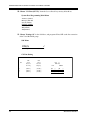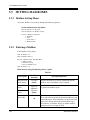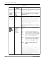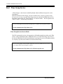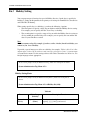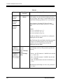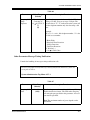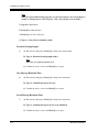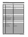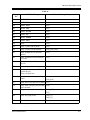
1
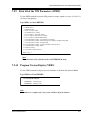
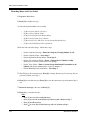
Voice Processing System
Installation Manual
Panaso
nic
Model
KX-TVS120
KX-TVS220 KX-TVS320
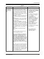
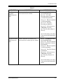
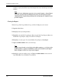
Thank you for purchasing a Panasonic Voice Processing System, Model KX-TVS120/KX-TVS220/KX-TVS320.
Please read this manual before installing, customizing, or operating the Voice Processing System.
Thank you for purchasing the Panasonic Model
Voice Processing System.
We are confident that it will provide your customer or client with many years of dependable
service.
This Voice Processing System was especially tailored for the American environment. For
example, it can be configured for English, a second language, or a third language:
System prompts—Recorded at the factory in English
User 1 prompts—Record in any language you like
User 2 prompts—Recorded at the factory in Spanish
These prompts guide subscribers and non-subscribers through specific VPS operations.
However, we would like to stress that for outside callers who merely need to be guided to an
extension, a mailbox, or other destinations (e.g., a fax machine), they can be greeted by a
Custom Service. This supports many languages as there are 12 keys on a touchtone phone and
you can record up to 100 Custom Service menus. One twelfth of these menus can be recorded
in one language if you desire. Another twelfth can be recorded in another language, and so on.
Thus callers can be guided entirely in their native languages. For a multi-cultural United States,
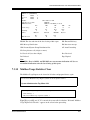
Custom Service is a truly powerful feature. Please see "Custom Service" in Appendix
A1 SYSTEM FEATURES for more details.
Note
This product is only for connection behind a suitable PBX and should not be connected directly
to the network.
Panasonic World Wide Web Address: http://www.panasonic.com
for customers in the United States or Puerto Rico.
2
Installation Manual
Important Information
Important Information
SAFETY REQUIREMENTS
• Follow all product warnings, cautions, and instructions.
• Handle the unit carefully. Do not drop or otherwise expose the unit to physical shock.
• If the unit malfunctions, disconnect the unit from the telephone line and check the line by
reconnecting the telephone. If the telephone operates properly, have the VPS repaired by a
qualified Panasonic Factory Service Technician.
• Install the unit so that the power cord is not obstructed in any way. Do not connect this unit
to an extension cord.
• Keep the unit free of dust, moisture, condensation, high temperature exposure (more than
40 °C {104 °F}) and vibration. Do not expose the unit to direct sunlight.
• Mount the unit on a stable wall surface. Do not mount the VPS inside of a separate
enclosure unless it is properly ventilated.
• Read all the information contained in this manual.
• This unit is designed to operate at one specific voltage and current setting. The proper
voltage and current required for this unit are listed on the product label.
• This unit is equipped with a 3-wire grounding plug. The plug will only fit into a grounded
power outlet. Do not modify this plug in any way. If it cannot be inserted into the outlet,
have the outlet replaced by a licensed electrician.
• Unplug and transport the unit to a service technician if the power supply cord is frayed or
damaged, if the cabinet is cracked or broken, or when the unit has been exposed to moisture,
has been dropped, or is not otherwise operating properly.
• Unplug the unit from its power source before cleaning.
• Do not block the vent slots and openings located on all sides of the unit.
• Do not disassemble this product. Dangerous electrical shock could result. The unit must
only be disassembled and repaired by qualified Panasonic Factory Service Technicians.
• Do not insert wires, pins, or any other material into the unit's vent slots or access points.
This could result in electrical shock and serious unit malfunction.
• Do not install the unit near water or moisture, heating appliances, or electrical noise
generating devices such as televisions, monitors, fluorescent lamps, or electric motors.
• Do not overload wall outlets. Overloaded outlets could result in fire and/or electrical shock.
• Do not use solvents, liquid cleaners, water, or abrasive powders to clean this unit. Use only
a damp soft cloth for cleaning.
• Do not use the telephone during a lightning storm or to report a gas leak in the vicinity of
the leak.
WARNING
TO PREVENT FIRE OR ELECTRICAL SHOCK, DO NOT EXPOSE THIS UNIT TO
RAIN OR MOISTURE.
Installation Manual
3
Important Information
When you ship the product
Carefully pack and send it prepaid, adequately insured and preferably in the original carton.
Attach a postage-paid letter, detailing the symptom, to the outside of the carton. DO NOT
send the product to the Executive or Regional Sales offices. They are NOT equipped to
make repairs.
Product service
Panasonic Factory Servicenters for this product are listed in the servicenter directory.
Consult your authorized Panasonic dealer for detailed instructions.
The serial number of this product may be found on the label affixed to the bottom of the unit.
You should note the serial number of this unit in the space provided and retain this book as a
permanent record of your purchase to aid in identification in the event of theft.
MODEL NO.:
SERIAL NO.:
For your future reference
DATE OF PURCHASE
NAME OF DEALER
DEALER’S ADDRESS
DEALER’S TEL. NO.
WARNING
THIS UNIT MAY ONLY BE INSTALLED AND SERVICED BY QUALIFIED
SERVICE PERSONNEL.
WHEN A FAILURE OCCURS WHICH RESULTS IN THE INTERNAL PARTS
BECOMING ACCESSIBLE, DISCONNECT THE POWER SUPPLY CORD
IMMEDIATELY AND RETURN THIS UNIT TO YOUR DEALER.
DISCONNECT THE TELECOM CONNECTION BEFORE DISCONNECTING THE
4
Installation Manual
Important Information
POWER CONNECTION PRIOR TO RELOCATING THE EQUIPMENT, AND
RECONNECT THE POWER FIRST.
THIS UNIT IS EQUIPPED WITH AN EARTHING CONTACT PLUG. FOR SAFETY
REASONS, THIS PLUG MUST ONLY BE CONNECTED TO AN EARTHING
CONTACT SOCKET WHICH HAS BEEN INSTALLED ACCORDING TO
REGULATIONS.
CAUTION
Danger of explosion if battery is incorrectly replaced.
Replace only with the same or equivalent type
recommended by the manufacturer.
Dispose of used batteries according to the
manufacturer's instructions.
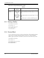
Note
Before you start setting or changing system parameters, we recommend that you turn off the
Call Progression Mode with the OFLN command. While off, the power LED of the VPS will
flash and the VPS will not answer any incoming call. After you finish programming, use the
ONLN command to turn on the Call Progression Mode (normal operation). Please see
7.2.1 Off-line Set (OFLN) and 7.2.2 On-line Set (ONLN) for more details.
Trademarks
• HyperTerminal is either a registered trademark or a trademark of HILGRAEVE,
INCORPORATED in the United States and/or other countries.
• IBM is a trademark of International Business Machines Corporation in the United
States.
• Procomm Plus is either a registered trademark or a trademark of DATASTORM
TECHNOLOGIES, INC. in the United States and/or other countries.
• Smartcom is either a registered trademark or a trademark of Hayes Microcomputer
Products, Inc. in the United States and/or other countries.
• All other trademarks identified herein are the property of their respective owners.
Installation Manual
5
Important Information
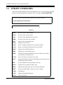
F.C.C. REQUIREMENTS AND RELEVANT INFORMATION
Notify The Telephone Company
This equipment complies with Part 68 of the FCC rules and the requirements adopted by the
ACTA. On the bottom of this equipment is a label that contains, among other information, a
product identifier in the following format:
• US:ACJVM04BKX-TVS220 (KX-TVS120/KX-TVS220)
• US:ACJVM04BKX-TVS320 (KX-TVS320)
If requested, this number must be provided to the telephone company.
Installation must be performed by a qualified professional installer. If required, provide the
telephone company with the following technical information:
• The telephone numbers to which the system will be connected
• Make: Panasonic
• Model: KX-TVS120/KX-TVS220/KX-TVS320
• FCC Registration No.: found on the bottom of the unit
• Ringer Equivalence No.: 0.4B
• Facility Interface Code: 02LS2
• Service Order Code: 9.0F
• Required Network Interface Jack: RJ11C
Ringer Equivalence No. (REN)
The REN is used to determine the number of devices that may be connected to a telephone line.
Excessive RENs on a telephone line may result in the devices not ringing in response to an
incoming call. In most but not all areas, the sum of RENs should not exceed five (5.0). To be
certain of the number of devices that may be connected to a line, as determined by the total
RENs, contact the local telephone company. For products approved after July 23, 2001, the
REN for this product is part of the product identifier that has the following format:
• US:ACJVM04BKX-TVS220 (KX-TVS120/KX-TVS220)
• US:ACJVM04BKX-TVS320 (KX-TVS320)
The digits represented by 04 are the REN without a decimal point (e.g., 03 is a REN of 0.3).
For earlier products, the REN is separately shown on the label.
Telephone Service Problems
If this equipment causes harm to the telephone network, the telephone company will notify you
in advance that temporary discontinuance of service may be required. But if advance notice
isn't practical, the telephone company will notify the customer as soon as possible. Also, you
will be advised of your right to file a complaint with the FCC if you believe it is necessary.
Changes in Telephone Company Communications Facilities, Equipment, Operations,
and Procedures
The telephone company may make changes in its facilities, equipment, operations or
procedures that could affect the operation of the equipment. If this happens the telephone
company will provide advance notice in order for you to make necessary modifications to
maintain uninterrupted service.
6
Installation Manual
Important Information
Trouble with this equipment
If trouble is experienced with this equipment, for repair or warranty information, please see the
attached warranty, which includes the Servicenter Directory. If the equipment is causing harm
to the telephone network, the telephone company may request that you disconnect the
equipment until the problem is resolved.
Connection to the Party Line
Connection to party line service is subject to state tariffs. Contact the state public utility
commission, public service commission or corporation commission for information.
Note
This equipment has been tested and found to comply with the limits for a Class A
digital device, pursuant to Part 15 of the FCC Rules. These limits are designed to
provide reasonable protection against harmful interference when the equipment is
operated in a commercial environment. This equipment generates, uses, and can
radiate radio frequency energy and, if not installed and used in accordance with the
instruction manual, may cause harmful interference to radio communications.
Operation of this equipment in a residential area is likely to cause harmful
interference in which case the user will be required to correct the interference at his
own expense.
CAUTION
Any change or modification made to the terminal equipment, not expressly approved by the
manufacturer, could void the user's authority to operate this equipment.
Installation Manual
7
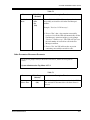
Table of Contents
Table of Contents
1
VOICE PROCESSING SYSTEM OVERVIEW
1.1 WHAT THE VPS CAN AND CANNOT DO............................................................ 14
1.1.1 Why Voice Processing?.............................................................................................. 14
1.1.2 Basic Operations......................................................................................................... 14
1.1.3 VPS Limitations ......................................................................................................... 15
1.2 SYSTEM ADMINISTRATION, MANAGEMENT, AND USE.............................. 16
1.2.1 System Administration ............................................................................................... 16
1.2.2 System Management .................................................................................................. 16
1.2.3 Subscriber Use............................................................................................................ 16
1.3 SYSTEM BASICS ....................................................................................................... 17
1.3.1 General ....................................................................................................................... 17
1.3.2 System Components ................................................................................................... 17
1.3.3 Which Phone Systems are Compatible?..................................................................... 23
1.3.4 Installer Equipment and Software Requirements ....................................................... 24
1.3.5 Specifications ............................................................................................................. 24
1.3.6 Hardware .................................................................................................................... 25
1.3.7 Expansion Capabilities ............................................................................................... 25
1.3.8 Internal Modem Card (KX-TVS320 only) ................................................................. 25
1.3.9 Recommendations for System Configuration ............................................................ 26
1.4 VOICE MAIL INTEGRATION ................................................................................ 28
1.4.1 General ....................................................................................................................... 28
1.4.2 Connection Examples—KX-TVS120 ........................................................................ 29
1.4.3 Connection Examples—KX-TVS220 ........................................................................ 31
1.4.4 Connection Examples—KX-TVS320 ........................................................................ 33
2
INSTALLATION
2.1 SAFETY PRECAUTIONS ......................................................................................... 38
2.1.1 Installation .................................................................................................................. 38
2.1.2 Wiring......................................................................................................................... 39
2.1.3 Environmental Requirements ..................................................................................... 40
2.2 UNPACKING .............................................................................................................. 41
2.3 MOUNTING THE VPS ON THE WALL................................................................. 42
2.4 FRAME GROUND CONNECTION ......................................................................... 44
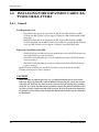
2.5 INSTALLATION STEPS ........................................................................................... 46
2.6 INSTALLING PORT EXPANSION CARDS: KX-TVS102 OR KX-TVS204 ...... 48
2.6.1 General ....................................................................................................................... 48
2.6.2 Installing the KX-TVS102 or KX-TVS204 Port Card ............................................... 49
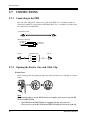
2.7 CONNECTIONS ......................................................................................................... 52
2.7.1 Connecting to the PBX ............................................................................................... 52
2.7.2 Opening the Ferrite Core and Cable Clip ................................................................... 52
2.7.3 Modular Plug Connection........................................................................................... 53
2.7.4 Port Cards ................................................................................................................... 53
2.7.5 Internal Modem Card (KX-TVS320 only) ................................................................. 56
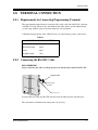
2.8 TERMINAL CONNECTION..................................................................................... 57
2.8.1 Requirements for Connecting Programming Terminal .............................................. 57
2.8.2 Connecting the RS-232C Cable.................................................................................. 57
8
Installation Manual
Table of Contents
2.8.3
3
RS-232C Signals .........................................................................................................58
INTEGRATING THE VPS WITH PANASONIC KX-T PHONE
SYSTEMS
3.1 GUIDELINES FOR INTEGRATION .......................................................................62
3.1.1 DPT or Inband Signaling?...........................................................................................62
3.1.2 Why Integration is Important ......................................................................................62
3.1.3 How the VPS and the PBX Communicate ..................................................................62
3.1.4 PBX Requirements for Integration..............................................................................63
3.2 PBX PARAMETERS AND PORT SETTINGS ........................................................66
3.2.1 General Guidelines and Definitions ............................................................................66
3.2.2 RS-232C Settings ........................................................................................................66
3.2.3 Port Settings ................................................................................................................66
3.2.4 PBX Interface Parameters ...........................................................................................67
3.3 CONNECTING THE VPS WITH PANASONIC KX-T SERIES PBXs ................70
3.3.1 VPS Programming for Inband Integration ..................................................................70
3.3.2 KX-TA series Programming for Inband Integration via the Manager's Extension.....71
3.3.3 KX-TD500 Programming for Inband Integration .......................................................74
3.3.4 KX-TD816, KX-TD1232, KX-TA1232 and KX-TD308 Programming for Inband
Integration via the Manager's Extension....................................................................83
3.3.5 KX-TD816, KX-TD1232, and KX-TA1232 Programming for Inband Integration via
the Operating and Maintenance Tool.........................................................................84
3.3.6 KX-TD308 Programming for Inband Integration via the Operating and Maintenance
Tool ............................................................................................................................87
4
INTEGRATING THE VPS WITH THE PANASONIC KX-T
DIGITAL PBX
4.1 GUIDELINES FOR DPT INTEGRATION ..............................................................92
4.1.1 Why DPT Integration is Important..............................................................................92
4.2 KX-TD500 PROGRAMMING FOR DIGITAL INTEGRATION ..........................94
4.3 CONNECTING THE VPS WITH THE PANASONIC KX-TD816, KX-TD1232,
KX-TA1232 AND KX-TD308 ..................................................................................103
4.3.1 KX-TD1232 Software Verification and Programming for DPT Integration via the
Manager's Extension ................................................................................................103
4.3.2 KX-TD1232 Software Verification and Programming for DPT Integration via the
Operating and Maintenance Tool.............................................................................108
4.3.3 KX-TD308 Software Verification and Programming for DPT Integration via the
Manager's Extension ................................................................................................111
4.4 COMMON DPT INTEGRATION FEATURES AND SETUP PROCEDURES ................. 117
4.4.1 Live Call Screening (LCS) Programming .................................................................117
4.4.2 Live Call Screening Password Assignment ..............................................................117
4.4.3 Live Call Screening Password Canceling .................................................................118
4.4.4 Live Call Screening Recording Mode Assignment via System Programming .........118
4.4.5 Live Call Screening Private/Hands-Free Mode Assignment via Station Programming ........... 119
4.4.6 Live Call Screening Assignment via PC Programming ............................................120
4.4.7 Live Call Screening Button Assignment via Station Programming..........................121
4.4.8 Live Call Screening Cancel Button Assignment via Station Programming..............121
4.4.9 Two-Way Recording Button Assignment via Station Programming........................122
4.4.10 Two-Way Transfer Button Assignment via Station Programming .........................123
Installation Manual
9
Table of Contents
4.4.11
4.4.12
4.4.13
4.4.14
4.4.15
4.4.16
4.4.17
5
Voice Mail Transfer Button Assignment via Station Programming ...................... 123
Button Assignment via PC Programming .............................................................. 124
Live Call Screening Activation .............................................................................. 126
Live Call Screening Password Control................................................................... 127
Two-Way Recording into Mailbox ........................................................................ 127
Two-Way Transfer into Mailbox............................................................................ 127
A Restriction on TWR/TWT Activation ................................................................ 127
CUSTOMIZING THE SYSTEM
5.1 STARTING UP .......................................................................................................... 130
5.1.1 Before Programming ................................................................................................ 130
5.1.2 Quick Setup .............................................................................................................. 130
5.1.3 Starting the Quick Setup........................................................................................... 131
5.2 PORT SETTING OPTIONS .................................................................................... 139
5.2.1 Custom Service Setting Example ............................................................................. 139
5.2.2 Custom Service Features .......................................................................................... 140
5.2.3 Custom Service Programming.................................................................................. 142
5.2.4 Recording Menus...................................................................................................... 145
5.2.5 Checking Operation.................................................................................................. 145
5.2.6 Voice Mail ................................................................................................................ 145
5.2.7 Mailbox Groups........................................................................................................ 146
5.2.8 Extension Groups ..................................................................................................... 146
5.2.9 Interview Service...................................................................................................... 147
5.2.10 Automated Attendant.............................................................................................. 148
5.2.11 Department Dialing Service ................................................................................... 148
5.2.12 Operator Service ..................................................................................................... 149
5.3 SETTING PORTS ..................................................................................................... 150
5.3.1 Port Service Menu .................................................................................................... 150
5.4 AUTOMATED ATTENDANT PARAMETERS.................................................... 152
5.4.1 Automated Attendant Menu ..................................................................................... 152
5.4.2 Department Dialing .................................................................................................. 152
5.4.3 Operator's Parameters ............................................................................................... 153
5.5 SETTING MAILBOXES .......................................................................................... 156
5.5.1 Mailbox Setting Menu .............................................................................................. 156
5.5.2 Entering a Mailbox ................................................................................................... 156
5.5.3 Deleting a Mailbox ................................................................................................... 160
5.5.4 Password Reset ......................................................................................................... 160
5.5.5 Mailbox Listing ........................................................................................................ 161
5.6 TRAINING THE SUBSCRIBER............................................................................. 162
6
FINAL SETUP
6.1 MESSAGE MANAGER'S MAILBOX (Mailbox 9998)......................................... 164
6.1.1 Accessing the Message Manager's Mailbox............................................................. 164
6.1.2 Main Menu of Message Manager's Service.............................................................. 164
6.1.3 Company Greetings (Enter #6*9998,5,1)................................................................. 165
6.1.4 Custom Service Greetings (Enter #6*9998,5,4)....................................................... 165
6.1.5 Customizing User Prompts (Enter #6*9998,5,6) ..................................................... 165
6.2 SETTING UP MAILBOXES.................................................................................... 167
6.2.1 Recording Personal Greetings .................................................................................. 167
10
Installation Manual
Table of Contents
6.2.2 Recording the Owner's Name....................................................................................168
6.3 BACKING UP THE SYSTEM..................................................................................169
7
SYSTEM MAINTENANCE AND TROUBLESHOOTING
7.1 INITIALIZING THE SYSTEM ...............................................................................172
7.2 UTILITY COMMANDS............................................................................................174
7.2.1 Off-line Set (OFLN)..................................................................................................175
7.2.2 On-line Set (ONLN)..................................................................................................175
7.2.3 Set Password (PASS) ................................................................................................175
7.2.4 Set Time (TIME) .......................................................................................................176
7.2.5 Print Reports at Specified Time (PSET) ...................................................................177
7.2.6 Error Log Display (ELOG) .......................................................................................178
7.2.7 Saving the System Data to the Backup Device (SAVE) ...........................................180
7.2.8 Loading New or Saved Data to the VPS (LOAD) ....................................................182
7.2.9 Print All of the VPS Parameters (GPRN) .................................................................183
7.2.10 Program Version Display (VERS) ..........................................................................183
7.2.11 Custom Service Report (CREP) ..............................................................................184
7.2.12 Custom Service Menu Access Count Clear (CCLR) ..............................................185
7.2.13 Message Waiting Lamp Retry Times (MWL) ........................................................185
7.2.14 Setting Minimum Recording Length (MRL) ..........................................................186
7.2.15 Modified Prompt List (MPLT)................................................................................186
7.2.16 Utility Command List (HELP) ................................................................................187
7.2.17 Quick Setup (QSET) ...............................................................................................188
7.2.18 Circuit Condition Display (LMON) ........................................................................188
7.2.19 Touchtone Information Display (PUTD) ................................................................189
7.2.20 Wait for Caller ID (WCID) .....................................................................................190
7.3 SYSTEM REPORTS..................................................................................................191
7.3.1 Mailbox Assignments................................................................................................192
7.3.2 COS (Class of Service) Assignments........................................................................192
7.3.3 System Service Report ..............................................................................................194
7.3.4 Call Account Report..................................................................................................195
7.3.5 Port Usage Report .....................................................................................................195
7.3.6 Port Usage Statistics Clear ........................................................................................196
7.3.7 Disk Usage Report ....................................................................................................197
7.3.8 Disk Usage Statistics Clear .......................................................................................198
7.3.9 Mailbox Usage Report ..............................................................................................198
7.3.10 Mailbox Usage Statistics Clear ...............................................................................199
7.3.11 Fax Call Report .......................................................................................................200
7.3.12 Fax Call Statistics Clear ..........................................................................................200
7.4 REMOTE PROGRAMMING (KX-TVS320 Only) ................................................201
7.5 TROUBLESHOOTING GUIDE ..............................................................................203
7.6 SPECIFICATIONS ....................................................................................................207
Appendix
A1
Appendix
B1
B2
A
SYSTEM FEATURES
SYSTEM FEATURES ...............................................................................................210
B
SYSTEM ADMINISTRATOR'S GUIDE
SYSTEM NAVIGATION ..........................................................................................240
SYSTEM ADMINISTRATION—MAILBOXES ....................................................245
Installation Manual
11
Table of Contents
B3
SYSTEM ADMINISTRATION—SETTING COS (CLASS OF SERVICE)
PARAMETERS........................................................................................................ 252
B4 SYSTEM ADMINISTRATION—PORT/TRUNK SERVICE .............................. 262
B4.1 Port Assignment........................................................................................................ 262
B4.2 Trunk Group Assignment ......................................................................................... 264
B5 SYSTEM ADMINISTRATION—SERVICE SETTINGS..................................... 267
B5.1 Automated Attendant Parameters ............................................................................. 267
B5.2 Custom Service ......................................................................................................... 275
B5.3 Caller ID Call Routing Parameters ........................................................................... 278
B6 SYSTEM ADMINISTRATION—SYSTEM PARAMETER SETTINGS ........... 281
B6.1 System Group Assignment ....................................................................................... 281
B6.2 Time Group Service.................................................................................................. 284
B6.3 Holiday Setting ......................................................................................................... 288
B6.4 Daylight Saving Time (DST).................................................................................... 290
B6.5 Prompt Setting .......................................................................................................... 291
B6.6 System Caller Name Announcement ........................................................................ 293
B6.7 Other Parameters....................................................................................................... 294
B7 SYSTEM ADMINISTRATION—HARDWARE SETTINGS .............................. 306
B7.1 RS-232C Parameters................................................................................................. 306
B7.2 Port Setting ............................................................................................................... 307
B7.3 PBX Interface Parameters......................................................................................... 308
Appendix
C1
C2
C3
C4
C5
C6
C7
C8
C9
C10
C11
Appendix
D1
D2
D3
D4
D5
D6
D7
D8
D9
C
SYSTEM MANAGER'S GUIDE
ACCESSING THE SYSTEM MANAGER'S MAILBOX ..................................... 318
SETTING UP MAILBOXES.................................................................................... 320
SETTING COS (CLASS OF SERVICE) PARAMETERS ................................... 323
SETTING THE SYSTEM CLOCK ......................................................................... 330
CHANGING THE SERVICE MODE SETTING .................................................. 332
CHANGING THE COMPANY GREETING SETTING ...................................... 334
INITIALIZING THE INTERNAL MODEM (KX-TVS320 Only)....................... 336
CHECKING SYSTEM USAGE (SYSTEM REPORTS)....................................... 337
DELIVERING MESSAGES..................................................................................... 339
CUSTOMIZING THE SYSTEM MANAGER'S MAILBOX ............................. 342
LISTENING TO SYSTEM MANAGER MESSAGES ........................................ 343
D
MESSAGE MANAGER'S GUIDE
ACCESSING THE MESSAGE MANAGER'S MAILBOX .................................. 346
MANAGING THE GENERAL DELIVERY MAILBOX ..................................... 348
SETTING UP MESSAGE WAITING NOTIFICATION...................................... 350
CUSTOMIZING THE MESSAGE MANAGER'S MAILBOX ............................ 353
SETTING THE SYSTEM CLOCK ......................................................................... 355
RECORDING MESSAGES...................................................................................... 357
REMOTE CALL FORWARDING SET ................................................................. 362
LIST OF PROMPTS FOR VOICE MAIL AND AA SERVICE .......................... 365
LIST OF MODIFIABLE PROMPTS...................................................................... 368
Glossary ........................................................................................................................... 421
INDEX .............................................................................................................................. 433
12
Installation Manual
VOICE PROCESSING SYSTEM OVERVIEW
Section 1
VOICE PROCESSING SYSTEM OVERVIEW
Installation Manual
13
VOICE PROCESSING SYSTEM OVERVIEW
1.1
WHAT THE VPS CAN AND CANNOT DO
1.1.1
Why Voice Processing?
The VPS handles incoming and outgoing calls. When a call comes in, it answers, forwards to
appropriate extensions, takes and stores messages, and notifies subscribers when messages are
left. Subscribers may send and transfer messages to other subscribers within the system. The
VPS is easy to use, helping callers through the system with step-by-step voice prompts.
Unlike handwritten messages or those left with answering services, VPS messages are
confidential; they are stored in a mailbox and retrieved only with the subscriber's password.
Other advantages of the VPS are clarity and accuracy, which are commonly lacking with
written messages. The messages come directly from the caller, in the caller's own voice. To
further ensure accuracy, the system allows the sender to correct or change messages before
saving them. Messages can be erased or transferred by the recipient.
1.1.2
Basic Operations
Greeting Callers:
The VPS greets callers with a prerecorded message that includes directions for leaving and
editing messages. The VPS can list single-digit numbers for each available extension or
mailbox. Callers who know the extension of the person they wish to reach may dial the
extension number at any time. Callers with rotary phones are transferred to a preprogrammed
destination (which is often an operator or the General Delivery Mailbox) to leave a message.
Sending Messages:
Callers can review and edit messages before leaving them in a mailbox. Subscribers can send
messages to an individual or to several mailboxes at once. The message sender can then verify
that the other subscriber has received the message.
Receiving Messages:
There are several different message notification methods that subscribers can use. They can
choose to be notified by message waiting lamp, beeper, or a call from the system to another
line. System programming determines whether a subscriber will be notified each time a
message is left. (Subscribers can choose to receive message notifications differently depending
on the time of day.) Mailbox parameters, which accommodate 5-100 messages, determine the
maximum length of messages. If the system is connected using DPT Integration, subscribers
can press a pre-assigned button to record conversations into their own mailboxes or other
subscribers' mailboxes while talking on the phone. DPT Integration also allows subscribers to
screen messages as they are being left, or intercept them if required.
14
Installation Manual
VOICE PROCESSING SYSTEM OVERVIEW
1.1.3
VPS Limitations
The VPS does not support:
UCD functions
UCD (Uniform Call Distribution) is a service that distributes calls evenly among extensions;
when all extensions are unavailable, it returns to callers to say that all extensions are busy. Calls
can be forwarded by the VPS to the KX-TD500/1232/816/308 floating number of a UCD
group. The call then rings at the next available phone.
The VPS supports UCD functions with very limited capabilities. Because the incoming call
is forwarded as an intercom path and not a DIL (direct in line), the following items will not
work:
• time table
• overflow function
• DISA message from a DISA card
• IRNA
Integration with the wrong PBX or with certain Key Systems presents limitations to the VPS'
standard functions. We do not recommend these systems for integration with the VPS. The
section 1.3.3 Which Phone Systems are Compatible? explains problems with compatibility.
Installation Manual
15
VOICE PROCESSING SYSTEM OVERVIEW
1.2
1.2.1
SYSTEM ADMINISTRATION,
MANAGEMENT, AND USE
System Administration
System Administration is accomplished by the installer using terminal emulation software. It
concerns setting and changing system parameters and diagnosing system problems.
1.2.2
System Management
Two system functions are performed by the customer: System Management and Message
Management.
System Management concerns changing system parameters through the System Manager's
Mailbox.
Message Management concerns recording voice prompts through the Message Manager's
Mailbox. These messages include Company Greetings, Company Name, Department Dialing
menu, Custom Service menus, voice labels for System Group Distribution Lists, user prompts,
multilingual selection menu and System Caller Names.
1.2.3
Subscriber Use
System users are called subscribers. Subscribers are assigned personal mailboxes which they
can customize. Subscribers can record their names, record personal greetings, set covering
extensions, record questions for an interview mailbox, set the message reception mode, set
incomplete call handling status, set call transfer status, enter Personal Group Distribution Lists,
set the message waiting lamp, and set notification by calling.
16
Installation Manual
VOICE PROCESSING SYSTEM OVERVIEW
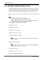
1.3
SYSTEM BASICS
1.3.1
General
Initial Configuration and Expansion Capabilities
• The KX-TVS120 is initially configured with 4 ports and approximately 32 h of storage,
and can be expanded to support 6 ports.
• The KX-TVS220 is initially configured with 4 ports and approximately 64 h of storage,
and can be expanded to support 12 ports.
• The KX-TVS320 is initially configured with 4 ports and approximately 128 h of storage,
and can be expanded to support 24 ports.
1.3.2
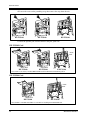
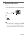
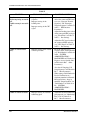
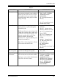
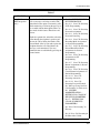
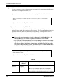
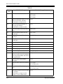
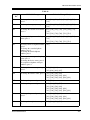
System Components
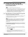
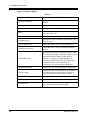
Main Cabinet—All Models
RS-232C
Connector
Ground Terminal
Fuse and fuse rating
AC Inlet
Panaso
nic
Power Switch
Power Indicator
Note
EIA port is at SELV.
Installation Manual
17
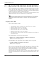
VOICE PROCESSING SYSTEM OVERVIEW
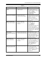
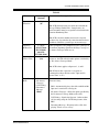
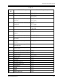
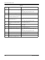
Inside View of the Main Cabinet—KX-TVS120
Grounding Strap
Slot for an optional
KX-TVS102 card
SLOT 3
SLOT 2
Factory-installed
KX-TVS204 card
SLOT 1
Rotary Switch
3.5" Hard Disk
Drive
Ferrite Core
Power Indicator
POWER
Note
Ports 1-6 are at TNV.
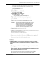
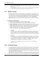
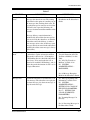
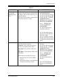
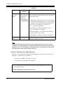
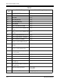
Inside View of the Main Cabinet—KX-TVS220
Grounding Strap
SLOT 3
SLOT 2
SLOT 1
Factory-installed
KX-TVS204 card
Slots For
Optional Port
Cards
Rotary Switch
3.5 "Hard Disk
Drive
Ferrite Core
Power Indicator
POWER
Note
Ports 1-12 are at TNV.
18
Installation Manual
VOICE PROCESSING SYSTEM OVERVIEW
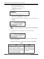
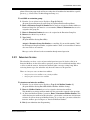
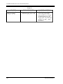
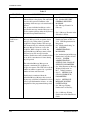
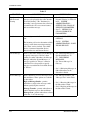
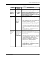
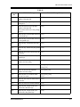
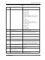
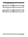
Inside View of the Main Cabinet—KX-TVS320
MODEM
SLOT 6
SLOT 5
SLOT 4
SLOT 3
SLOT 2
SLOT 1
Internal Modem
Card
Slots For
Optional Port
Cards
Factory-installed
KX-TVS204 card
Grounding Strap
3.5" Hard Disk
Drive
DIP Switch
Ferrite Cores
Power Indicator
Cable Clip
Note
Ports 1-24 are at TNV.
System Components
Power Indicator:
Indicates the system status: when flashing, the system is off-line (not ready to receive calls).
RS-232C Connector:
Connects an ASCII or VT terminal to the VPS that is necessary to program the system.
Ground Terminal:
Should be connected to a ground source with less than 1
resistance.
Fuse:
Protects the system from power line surges and should only be replaced with the same type.
Please see the fuse socket on the cabinet for the value of the fuse.
AC Inlet:
Connects the power cable to an AC outlet dedicated to the VPS.
Power Switch:
Starts the system and begins the self-test.
SAFETY PRECAUTION: When making any connections or removing the cover, be sure the
power switch is switched off.
Internal Modem Card—KX-TVS320:
Modem card for remote administration.
Installation Manual
19
VOICE PROCESSING SYSTEM OVERVIEW
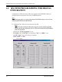
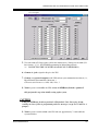
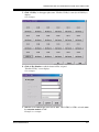
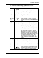
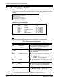
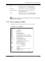
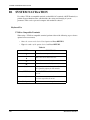
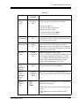
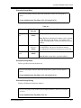
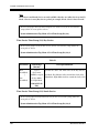
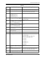
MODE (DIP Switch)—KX-TVS320:
By setting one of the following positions and executing power down and up, you can achieve
a desired result:
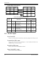
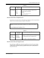
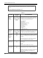
Table 1
Position
Additional Function
0
1•
2•
3•
4•
0
0
0
0
1
1
1
1
Normal setting. (All switches in 0 position.)
1
1•
2•
3•
4•
0
0
0
0
1
1
1
1
Initializes RS-232C parameters.
RS-232C default parameters: 9,600, N, 8, 1
2*
1•
2•
3•
4•
0
0
0
0
1
1
1
1
Auto Configuration is automatically executed and
all ports are set for Automated Attendant service.
3*
1•
2•
3•
4•
0
0
0
0
1
1
1
1
Auto Configuration is automatically executed and
all ports are set for Voice Mail service.
4
5
6
Reserved.
1•
2•
3•
4•
0
0
0
0
1
1
1
1
1•
2•
3•
4•
0
0
0
0
1
1
1
1
7
8
Initializes the VPS. Clears all voice data (except
User 1 and User 2 prompts) and returns all system
parameters to the default setting.
Test Mode (Hard Disk Drive Read/Write Test)
Reserved.
1•
2•
3•
4•
0
0
0
0
1
1
1
1
9-11
Initializes the VPS. Clears all voice data and
returns all system parameters to the default setting.
CAUTION: User 1 and User 2 Prompts will be
erased!
Reserved.
12
1•
2•
3•
4•
0
0
0
0
1
1
1
1
All service prompts are set to System Prompts.
13
1•
2•
3•
4•
0
0
0
0
1
1
1
1
All service prompts are set to User 1 Prompts.
14
1•
2•
3•
4•
0
0
0
0
1
1
1
1
All service prompts are set to User 2 Prompts.
15
Reserved.
* For Panasonic KX-T series telephone systems with DPT Integration.
To change the position, use a pointed object, such as a pen, etc.
20
Installation Manual
VOICE PROCESSING SYSTEM OVERVIEW
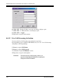
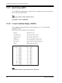
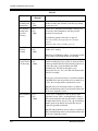
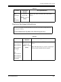
MODE (Rotary Switch)—KX-TVS120 and KX-TVS220:
By setting one of the following positions and executing power down and up, you can achieve
a desired result:
Table 2
Position
Additional Function
0
Normal setting.
1
Initializes RS-232C parameters.
RS-232 default parameters: 9,600, N, 8, 1
2*
Auto Configuration is automatically completed
and all ports are set for Automated Attendant
service.
3*
Auto Configuration is automatically completed
and all ports are set for Voice Mail service.
4
Reserved
5
Initializes the VPS. Clears all voice data (except
User 1 and User 2 prompts) and returns all system
parameters to the default setting.
6
Test Mode (Hard Disk Drive Read/Write Test)
7
Reserved
8
Initializes the VPS. Clears all voice data and
returns all system parameters to the default setting.
CAUTION: User 1 and User 2 Prompts will be
erased!
9
Reserved
* For Panasonic KX-T series telephone system with DPT Integration.
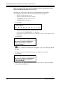
When setting the DIP/Rotary Switch to any position (except 0):
1. Disconnect the station wire(s) and wait a few minutes.
2. Turn the power switch off at the VPS.
3. Set the DIP/Rotary Switch.
4. Turn the power switch back on at the VPS.
5. Connect the station wire(s) to the VPS and wait approximately 5 min.
6. Return the DIP/Rotary Switch to position 0.
Grounding Strap:
Protects the printed circuit board from static electricity.
(Ground) SAFETY PRECAUTION: Discharge any body static by touching the metal bar.
Installation Manual
21
VOICE PROCESSING SYSTEM OVERVIEW
Optional Port Cards:
The following types of port cards can be installed in the VPS.
• Four digital port expansion cards (KX-TVS204)
• Two digital/analog port expansion cards (KX-TVS102)
SLOT 2 of the KX-TVS120 is not available for installing the KX-TVS204 card.
KX-TVS102 consists of the following 2 cards:
• Telephone line interface card
• Digital processor (DSP) card
The telephone line interface transmits and receives analog and digital signals to and from
the telephone line. The analog input signal is digitized at a sampling rate of 8 kHz to create
a 16-bit digital signal.
The DSP has the following features:
• Voice Compression and Decompression
• Touchtone Detection
• Touchtone Generation
• Call Progress Tone Detection
KX-TVS204 consists of a telephone line interface and a DSP. The telephone interface of the
KX-TVS204 transmits and receives ONLY digital signals with a Panasonic KX-TD or KXTA1232 Digital PBX. The DSP has the same features as the KX-TVS102.
Hard Disk Drive:
(One/system) Stores the proprietary system program, the system administration table, and the
voice prompts; has the recording area for the messages from callers. (The hard disk is
controlled by the central micro processor.)
Note: The actual Hard Disk Drive mounted on your VPS may look different from the one
shown in the corresponding illustration provided in the beginning of this section.
CPU Board:
(One/system) Main processing unit for the system. Comprised of central microprocessor,
ROM, dynamic RAM, system controller, DIP Switch (KX-TVS320) or Rotary Switch (KXTVS120 and KX-TVS220), and an RS-232C interface.
22
Installation Manual
VOICE PROCESSING SYSTEM OVERVIEW
1.3.3
Which Phone Systems are Compatible?
We recommend integration with the following Panasonic phone systems:
• Panasonic KX-TD500
• Panasonic KX-TD1232
• Panasonic KX-TA1232
• Panasonic KX-TD816
• Panasonic KX-TA series
• Panasonic KX-TD308
We cannot guarantee adequate integration of the VPS with other PBX systems or with Key
Systems. If the customer does not have a recommended Panasonic PBX system, be sure that
the system has the features listed below.
The PBX should have the following features for successful integration:
• Single line (tip/ring) port circuits (Some PBXs need an OPX card to provide this
connection.)
• Station to station touchtone signaling
• Message Waiting Notification from an SLT (single-line telephone)
• Screened transfer from an SLT
• Message Waiting Notification on proprietary (multi-line) sets (message waiting lamp
accessed by dialing on/off codes)
If the PBX does not have these features, VPS operation will be limited.
See 3.1.4 PBX Requirements for Integration. You will find the following information about
each feature listed:
• Description
• Limitations of the system without the feature
• Tests to determine whether the PBX has the feature
VOICE MAIL
The recommended Panasonic PBX systems have Follow-on ID and Inband Integration. When
callers are transferred to an extension that is forwarded to Voice Mail, Follow-on ID sends
callers directly to the mailbox. Without Follow-on ID, the caller would have to re-enter the
mailbox number when connected to Voice Mail.
Touchtone Integration enables the VPS to recognize the current state of the call and improve
its call handling performance. When enabled, the PBX informs the VPS of the status of the call
(busy, answered, ringing, etc.) by sending a code with touchtones before sending the normal
call progress tones. For example, when a caller hangs up before making a selection, the PBX
sends # 9 to the VPS port that answered. This informs the VPS that the caller has hung up.
Upon receiving these digits, the VPS goes on-hook and is ready to handle another call.
DPT Integration is available when the VPS is connected to a Panasonic KX-TD series or KX-
Installation Manual
23
VOICE PROCESSING SYSTEM OVERVIEW
TA1232 PBX (depending on the software version). This DPT Integration provides the VPS
with more information than Touchtone Integration. This information enables the system to
identify the extension number of the caller, know where from and why the call is forwarded,
and recognize what the caller wants to do. Some features are available only with DPT
Integration (Remote Call Forwarding Set, Live Call Screening, Two-Way Recording, TwoWay Transfer, Direct Mailbox Access, Intercom Paging, Auto Configuration, Caller Name
Announcement [system/personal], Caller ID Call Routing, Personal Greeting for Caller ID,
Time Synchronization with PBX).
1.3.4
Installer Equipment and Software Requirements
The installer must have a personal computer or data terminal equipped with terminal
emulation software. We suggest that you use something like HyperTerminal by HILGRAEVE.
Use the personal computer to program the VPS. Terminal emulation software enables the
keyboard to be used as a data entry device.
While both the personal computer and data terminal are working, the personal computer allows
screens to be saved in a file throughout the process. It is often helpful to retrieve these files later
if technical support is needed.
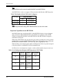
1.3.5
Specifications
Table 3
Compression Rate: 32 Kbps
Ports (maximum): • KX-TVS120: 6 ports
• KX-TVS220: 12 ports
• KX-TVS320: 24 ports
Voice Storage (approximate): • KX-TVS120: 32 h
• KX-TVS220: 64 h
• KX-TVS320: 128 h
Custom Services: 100
Message Retention: 1 to 30 days or unlimited
Number of Mailboxes: • KX-TVS120: 62 Subscriber and 2 Manager
Mailboxes
• KX-TVS220 and KX-TVS320: 1022
Subscriber and 2 Manager Mailboxes
Number of Messages per Mailbox: 100 maximum (programmable)
Internal Modem (KX-TVS320 only): Maximum data transfer rate at 33600 bps.
24
Installation Manual
VOICE PROCESSING SYSTEM OVERVIEW
1.3.6
Hardware
Table 4
1.3.7
KX-TVS120
KX-TVS220
KX-TVS320
• One Hard Disk Drive
• One Port Card (KXTVS204)
• One Optional Port Card
Slot for KX-TVS102 Card
• One RS-232C Connector
• One Rotary Switch
• One Hard Disk Drive
• One Port Card (KXTVS204)
• Two Optional Port Card
Slots for KX-TVS102
and/or KX-TVS204 Cards
• One RS-232C Connector
• One Rotary Switch
• One Hard Disk Drive
• One Port Card (KXTVS204)
• One Internal Modem Card
• Five Optional Port Card
Slots for KX-TVS102
and/or KX-TVS204 Cards
• One RS-232C Connector
• One DIP Switch (4-bit)
Expansion Capabilities
Expansion requires additional port card(s): KX-TVS102 or KX-TVS204.
• The KX-TVS102 card has 2 digital/analog ports, and the ports are increased in
increments of 2.
• The KX-TVS204 card has 4 digital ports, and the ports are increased in increments of 4.
Both the KX-TVS102 and the KX-TVS204 card can be installed in all models. (But SLOT 2
of the KX-TVS120 is not available for installing the KX-TVS204 card.)
1.3.8
Internal Modem Card (KX-TVS320 only)
An internal modem card is installed in the KX-TVS320 prior to factory shipment. This card is
necessary for programming and maintenance from remote locations.
The maximum data transfer rate of the internal modem is 33600 bps.
Installation Manual
25
VOICE PROCESSING SYSTEM OVERVIEW
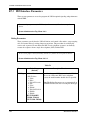
1.3.9
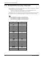
Recommendations for System Configuration
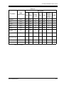
General guideline: a ratio of 6/1 (for every 6 lines, 1 port). There are 2 questions to ask when
considering how many ports are desirable:
• Are the ports answering all incoming calls or just forwarded/transferred calls?
• If they are answering incoming calls, how busy are the lines?
The guideline above (6/1) usually works well with moderate traffic. However, this may have
to be modified for heavy traffic. Recommendations are outlined in the following charts.
Notes
• The KX-TVS120 can support a maximum of 6 ports.
• The KX-TVS220 can support a maximum of 12 ports.
• The KX-TVS320 can support a maximum of 24 ports.
PBX
CO Lines
1-6
7-12
13-18
19-24
25-30
31-36
37-42
43-48
49-54
55-60
61-66
67-72
73-78
79-84
85-90
91-96
97-102
103-108
109-114
115-120
121-126
127-132
133-138
139-144
26
VPS
Port
1
2
3
4
5
6
7
8
9
10
11
12
13
14
15
16
17
18
19
20
21
22
23
24
Installation Manual
VOICE PROCESSING SYSTEM OVERVIEW
One port may not support an Automated Attendant configuration with 5 CO lines. The
preceding recommendations for Automated Attendant ports may have to be modified for heavy
traffic.
PBX
CO Lines
1-4
5-8
9-12
13-16
17-20
21-24
25-28
29-32
33-36
37-40
41-44
45-48
49-52
53-56
57-60
61-64
65-68
69-72
73-76
77-80
81-84
85-88
89-92
93-96
Installation Manual
VPS
Port
1
2
3
4
5
6
7
8
9
10
11
12
13
14
15
16
17
18
19
20
21
22
23
24
27
VOICE PROCESSING SYSTEM OVERVIEW
1.4
VOICE MAIL INTEGRATION
1.4.1
General
DPT Integration
To the Panasonic KX-T series PBX that uses DPT Integration, the VPS ports look like digital
extensions. The PBX thinks that the VPS is a digital phone, and the VPS mimics all actions of
a digital set. Another advantage of DPT Integration is that the 2B+D communication provides
2 VPS ports for each Digital Station port. Communication between the VPS and the PBX
through DPT Integration requires the proper software level in the PBX and 4-wire connections
for each port. To communicate between the VPS and the PBX through DPT Integration, the
PBX and VPS must be programmed to work together.
DPT Integration is available when the VPS is connected to a KX-TD series and KX-TA1232
PBX with the proper software level.
Notes
To use DPT Integration, the lowest numbered jack of the VPS must be connected to the
lowest numbered jack assigned as a Voice Mail Port Assignment in the PBX. See the DPT
connection example(s) for your VPS model in the following section,
1.4.2 Connection Examples—KX-TVS120,
1.4.3 Connection Examples—KX-TVS220, or
1.4.4 Connection Examples—KX-TVS320.
Connect the other jacks to the VPS in the order of Voice Mail Port Assignment in the PBX.
Inband/None Integration
To the PBX, the VPS looks like SLT sets through standard single-line (tip/ring) telephone
interfaces.
28
Installation Manual
VOICE PROCESSING SYSTEM OVERVIEW
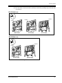
1.4.2
Connection Examples—KX-TVS120
DPT Integration
For example, when you mount 1 KX-TVS204 card and 1 KX-TVS102 card, you can use 6 VPS
ports in total by connecting 3 jacks of the KX-TD series or KX-TA1232 PBX to 3 jacks of the
KX-TVS120.
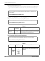
Notes
• The KX-TA1232 supports a maximum of 4 jacks as VPS ports.
• SLOT 2 of the KX-TVS120 is not available for installing the KX-TVS204 card.
Connection Example (KTVS204 1, KX-TVS102 1, DPT Integration Mode)
KX-TVS120
PBX (KX-TD1232)
SLOT 2
Jack 3
Jack 3
Jack 4
Port 5 Port 6
Jack 2
SLOT 1
Jack 1
Jack 1
Jack 2
Port 1 Port 2 Port 3 Port 4
Assigned as DPT VPS ports
SLOT 3
SLOT 2
SLOT 1
SLOT 1
Telephone Line
Modular Jacks
The lowest numbered
jack on the slot.
Connect the odd-numbered jack on the KX-TVS102 card to your PBX (see the diagram
above). The VPS will support 2 ports for the KX-TVS102 card, with only one jack connected.
Note
Do not connect the even-numbered jacks on the KX-TVS102 card.
Installation Manual
29
VOICE PROCESSING SYSTEM OVERVIEW
Inband/None Integration
Connection Example (KX-TVS102 2, Inband/None Integration Mode)
KX-TVS120
PBX (KX-TD1232)
Jack 4
SLOT 2
Jack 3
Jack 2
SLOT 1
Jack 1
Jack 3
Jack 4
Port 3
Port 4
Jack 1
Jack 2
Port 1
Port 2
SLOT 3
SLOT 2
SLOT 1
SLOT 1
Telephone Line
Modular Jacks
The lowest numbered
jack on the slot.
Connect both jacks on each KX-TVS102 card to your PBX (see the diagram above). The VPS
will support 2 ports for each KX-TVS102 card, with both jacks connected.
30
Installation Manual
VOICE PROCESSING SYSTEM OVERVIEW
1.4.3
Connection Examples—KX-TVS220
DPT Integration
For example, when you mount 3 KX-TVS204 cards, you can use 12 VPS ports in total by
connecting 6 jacks of the KX-TD series or KX-TA1232 PBX to 6 jacks of the KX-TVS220.
Note
The KX-TA1232 supports a maximum of 4 jacks as VPS ports.
Connection Example (KX-TVS204 3)
PBX (KX-TD1232)
KX-TVS220
Jack 6
SLOT 3
Jack 5
Jack 4
Jack 5
Port 9 Port 10 Port 11 Port 12
Jack 3
SLOT 2
Jack 3
Jack 2
SLOT 1
Jack 1
Jack 6
Jack 4
Port 5 Port 6 Port 7 Port 8
Jack 1
Jack 2
Port 1 Port 2 Port 3 Port 4
Assigned as DPT VPS ports
SLOT 3
SLOT 2
SLOT 1
SLOT 1
Telephone Line
Modular Jacks
Installation Manual
The lowest numbered
jack on the slot.
31
VOICE PROCESSING SYSTEM OVERVIEW
Connection Example (KX-TVS102 3, DPT Integration Mode)
PBX (KX-TD1232)
KX-TVS220
Jack 5
Jack 3
SLOT 3
Jack 2
SLOT 2
Jack 1
SLOT 1
Jack 6
Port 9 Port 10
Jack 4
Jack 3
Port 5 Port 6
Jack 2
Jack 1
Port 1 Port 2
Assigned as DPT VPS ports
SLOT 3
SLOT 2
SLOT 1
SLOT 1
Telephone Line
Modular Jacks
The lowest numbered
jack on the slot.
Connect the odd-numbered jack on each KX-TVS102 card to your PBX (see the diagram
above). The VPS will support 2 ports for each KX-TVS102 card, with only one jack connected.
Note
Do not connect the even-numbered jacks on the KX-TVS102 card.
32
Installation Manual
VOICE PROCESSING SYSTEM OVERVIEW
Inband/None Integration
Connection Example (KX-TVS102 3, Inband/None Integration Mode)
PBX (KX-TD1232)
KX-TVS220
Jack 6
SLOT 3
Jack 5
Jack 4
SLOT 2
Jack 3
Jack 2
SLOT 1
Jack 1
Jack 5
Jack 6
Port 9
Port 10
Jack 3
Jack 4
Port 5
Port 6
Jack 1
Jack 2
Port 1
Port 2
SLOT 3
SLOT 2
SLOT 1
SLOT 1
Telephone Line
Modular Jacks
The lowest numbered
jack on the slot.
Connect both jacks on each KX-TVS102 card to your PBX (see the diagram above). The VPS
will support 2 ports for each KX-TVS102 card, with both jacks connected.
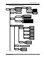
1.4.4
Connection Examples—KX-TVS320
DPT Integration
For example, when you mount 6 KX-TVS204 cards, you can use 24 VPS ports in total by
connecting 12 jacks of the KX-TD series or KX-TA1232 PBX to 12 jacks of the VPS.
Note
The KX-TA1232 supports a maximum of 4 jacks as VPS ports.
Installation Manual
33
VOICE PROCESSING SYSTEM OVERVIEW
Connection Example (KX-TVS204 6)
PBX (KX-TD500)
VPS
VPS Card 2
Jack 3
Jack 12
Jack 10
Jack 9
Port 19 Port 20 Port 17 Port 18
SLOT 5
Jack 2
Jack 1
Jack 11
Port 23 Port 24 Port 21 Port 22
SLOT 6
Jack 4
VPS Card 1
Jack 7
Jack 8
Port 15 Port 16 Port 13 Port 14
Jack 6
Port 11 Port 12 Port 9 Port 10
Jack 4
Port 7 Port 8 Port 5 Port 6
Jack 2
Jack 1
Port 3 Port 4 Port 1 Port 2
SLOT 1
Jack 2
Jack 1
Jack 3
SLOT 2
Jack 4
Jack 3
Jack 5
SLOT 3
Jack 6
Jack 5
Jack 7
SLOT 4
Jack 8
Assigned as DPT VPS ports
MODEM
SLOT 6
SLOT 5
SLOT 4
SLOT 3
SLOT 1
34
SLOT 1
SLOT 2
Telephone Line
Modular Jacks
The lowest numbered
jack on the slot.
Installation Manual
VOICE PROCESSING SYSTEM OVERVIEW
Connection Example (KX-TVS102 6, DPT Integration Mode)
VPS
PBX (KX-TD500)
Jack 12
Jack 6
Jack 11
Port 21 Port 22
Jack 9
Port 17 Port 18
Jack 7
Port 13 Port 14
Jack 5
Port 9 Port 10
Jack 3
Port 5 Port 6
Jack 1
Port 1 Port 2
SLOT 1
Jack 2
Jack 1
SLOT 2
Jack 4
Jack 2
SLOT 3
Jack 6
Jack 3
SLOT 4
Jack 8
Jack 4
SLOT 5
Jack 10
Jack 5
SLOT 6
VPS Card 1
Assigned as DPT VPS ports
MODEM
SLOT 6
SLOT 5
SLOT 4
SLOT 3
SLOT 1
SLOT 1
SLOT 2
Telephone Line
Modular Jacks
The lowest numbered
jack on the slot.
Connect the odd-numbered jack on each KX-TVS102 card to your PBX (see the diagram
above). The VPS will support 2 ports for each KX-TVS102 card, with only one jack connected.
Note
Do not connect the even-numbered jacks on the KX-TVS102 card.
Installation Manual
35
VOICE PROCESSING SYSTEM OVERVIEW
Inband/None Integration
Connection Example (KX-TVS102 6, Inband/None Integration Mode)
PBX
VPS
Jack 9
Port 18
Port 17
Jack 8
Jack 7
Port 14
Port 13
Jack 6
Jack 5
Port 10
Port 9
Jack 4
Jack 3
Port 6
Port 5
Jack 2
Jack 2
Jack 1
Jack 1
Port 2
Port 1
Jack 9
Jack 8
Jack 7
Jack 6
Jack 5
Jack 4
Jack 3
SLOT 1
Jack 10
Jack 10
SLOT 2
Port 21
SLOT 3
Port 22
Jack 11
SLOT 4
Jack 11
SLOT 5
Jack 12
SLOT 6
Jack 12
MODEM
SLOT 6
SLOT 5
SLOT 4
SLOT 3
SLOT 1
SLOT 1
SLOT 2
Telephone Line
Modular Jacks
The lowest numbered
jack on the slot.
Connect both jacks on each KX-TVS102 card to your PBX (see the diagram above). The VPS
will support 2 ports for each KX-TVS102 card, with both jacks connected.
36
Installation Manual
INSTALLATION
Section 2
INSTALLATION
Installation Manual
37
INSTALLATION
2.1
SAFETY PRECAUTIONS
Please read the following precautions before installing the VPS.
2.1.1
Installation
The VPS needs to be mounted on a wall. Improper placement of the system may result in
malfunction, noise, or discoloration. Avoid installing the VPS in the following places:
• in direct sunlight; in hot, cold, or humid places
• in new areas where there are thermal springs, etc. (where sulfuric gas may damage the
equipment or contacts).
• where shocks or vibrations are frequent or strong.
• in dusty places or places where water or oil may come in contact with the unit.
• near high frequency generating devices such as sewing machines, elevators or electric
welders.
• on or near computers, telexes, or other office equipment; near microwave ovens or air
conditioners. (Ideally, the VPS should not be in the room with these items and should be
at least 1.8 m {6 feet} away from televisions.)
Do not obstruct the areas around the PBX and the VPS. Both require space above for cooling
and space on the sides for maintenance and inspection.
38
Installation Manual
INSTALLATION
2.1.2
Wiring
• To assure good quality telephone connection, it is recommended new and modifications to
existing installation of customer premise wiring shall use solid twisted pair copper
conductors with minimum 24 gauge that comply with the electrical specifications for
Category 3 wiring as detailed in ANSI/EIA/TIA-570A Building Wiring Standards.
• Do not wire the telephone cable parallel to an AC power source, computer, etc. If cables
are run near those wires, shield them with metal tubing or use shielded cables and ground
the shields.
• Use protectors if running cables on the floor. Avoid running cables under carpets.
• Avoid sharing a 120 V AC power supply for computers, telexes, and other office equipment
with the VPS. Induction noise from such equipment may interrupt the VPS operation.
When making any connections or removing the cover, be sure the power switch is turned off.
When installing telephone wiring, basic safety precautions should always be followed to
reduce the risk of fire, electric shock and injury to persons, including the following:
• Never install telephone wiring during a lightning storm.
• Never install telephone jacks in wet locations unless the jack is specifically designed for
wet locations.
• Never touch uninsulated telephone wires or terminals unless the telephone line has been
disconnected at the network interface.
• Use caution when installing or modifying telephone lines.
Note
If you live in an area that can have frequent power failures, we strongly recommend that you
purchase a suitable UPS (uninterruptible power supply) for your VPS (and PBX if needed).
The power rating of your VPS may be found in the specifications.
Installation Manual
39
INSTALLATION
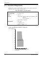
2.1.3
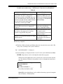
Environmental Requirements
The hard disk is sensitive to cold, heat, dryness, humidity, shock, vibration, and magnetic
fields. Please observe the conditions specified below.
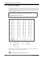
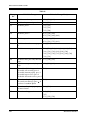
Table 5 Hard Disk Drive Usage Environment
Operating Temperature
: 5 °C to 40 °C {41 °F to 104 °F}
Operating Humidity
: See Graph 1 below.
Shock
: Under 5 G
Vibration
: 5 Hz to 22 Hz : 0.0042 cm {0.020 inch} displacement; double
amplitude,
1 octave per minute.
23 Hz to 350 Hz : Under 0.5 G
Magnetic Field
: DC : 0.6 mT
to 700 kHz : 0.7 µ T
700 kHz to 1.5 MHz : 3 µ T
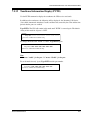
Graph 1: Allowable Relative Humidity vs. Temperature
Relative Humidity (%)
100
90
80
70
60
50
Operating Area
40
30
20
10
0
5
41
15
59
25
77
35
95
45
113
55
131
(˚C)
(˚F)
Temperature
40
Installation Manual
INSTALLATION
2.2
UNPACKING
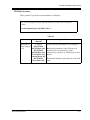
Unpack the box and check the items below.
Table 6
Main Unit
1
AC Cord
1
Screws (Wall Mounting)
3
Anchor Plugs (Wall Mounting)
3
Installation Manual
41
INSTALLATION
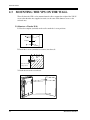
2.3
MOUNTING THE VPS ON THE WALL
The wall where the VPS is to be mounted must be able to support the weight of the VPS. If
screws other than the ones supplied are used, use the same-sized diameter screws as the
enclosed ones.
To Mount on a Wooden Wall:
1. Place the template (included) on the wall to mark the 3 screw positions.
Template
;;
;;
2. Install the 3 screws (included accessories) into the wall.
Wooden
Wall
Drive the screw
to this position.
3. Hook the unit on the screw heads.
42
Installation Manual
INSTALLATION
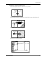
To Mount on a Concrete or Mortar Wall:
1. Place the template on the wall to mark the 3 screw positions.
Template
2. Drill 3 holes and drive the anchor plugs (included) with a hammer, flush with the wall.
To the wall surface
Anchor Plug
Concrete or
Mortar Wall
6.4 mm
(1/4 inch)
29 mm
(1-1/8 inch)
;;
;;
3. Install the 3 screws into the anchor plugs.
Drive the screw
to this position.
4. Hook the unit on the screw heads.
Installation Manual
43
INSTALLATION
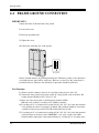
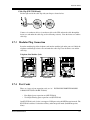
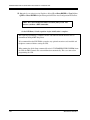
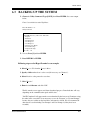
2.4
FRAME GROUND CONNECTION
IMPORTANT!!!
Connect the frame of the main unit to the ground.
1. Loosen the screw.
2. Insert the grounding wire.
3. Tighten the screw.
4. Connect the grounding wire to the ground.
Panaso
nic
To ground
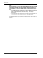
In most of North America, the ground provided by the "Third wire ground" at the commercial
or residential power outlet will be satisfactory. However, in some cases this ground may be
installed incorrectly. Therefore, the following test procedure should be performed.
Test Procedure
1. Obtain a suitable voltmeter and set it for a possible reading of up to 250 V AC.
2. Connect the meter probes between the 2 main AC voltage points on the wall outlet. The
reading obtained should be 108 V AC-132 V AC.
3. Move one of the meter probes to the third prong terminal (GND).
Either the same reading or a reading of 0 V should be obtained.
4. If a reading of 0 V at 1 terminal and a reading of 108 V AC-132 V AC at the other terminal
is not obtained, the outlet is not properly grounded. This condition should be corrected by
a qualified electrician (per article 250 of the National Electrical Code).
5. If a reading of 0 V at 1 terminal and a reading of 108 V AC-132 V AC at the other terminal
is obtained, then set the meter to the "OHMS/RX1" scale, place 1 probe at the GND
Terminal and the other probe at the terminal which gave a reading of 0 V. A reading of less
44
Installation Manual
INSTALLATION
than 1 should be obtained. If the reading is not obtained, the outlet is not adequately
grounded. See a qualified electrician.
Installation Manual
45
INSTALLATION
2.5
INSTALLATION STEPS
The following is an overview of the standard installation process using DPT Integration. When
necessary, other sections in this manual have been referenced for more detailed descriptions or
instructions.
1. Obtain a list of current users, their extension numbers, their departments, and the type of
systems they use (mailbox, no mailbox, beeper, car phone, etc.).
2. Assess your customers' needs before setting up the system. You will save yourself time later
by giving customers what they need up front. Ask the office manager how the VPS will be
used. Give examples.
Recommend that your customer use a word processor to log the greetings. You will find
these files much more easily than the worksheet pages if you need to make changes down
the road.
3. Connect the power cord to the VPS, then turn power switch on.
CAUTION
The power supply cord is used as the main disconnect device. Ensure that the socket-outlet
is located/installed near the equipment and is easily accessible.
4. If necessary, install optional port expansion cards (see 2.6 INSTALLING PORT
EXPANSION CARDS: KX-TVS102 OR KX-TVS204).
5. Standard Initialization (For DPT Integration Connection)
a) Program the ports of the PBX for voice processing (see Section 4 INTEGRATING THE
VPS WITH THE PANASONIC KX-T DIGITAL PBX).
Program the KX-TD500, the KX-TD1232, the KX-TA1232, the KX-TD816 or the
KX-TD308 for Voice Mail integration.
• KX-TD500, KX-TD816, KX-TD1232, KX-TA1232, KX-TD308
Program may be performed on-site or at the office.
All memory is stored and will be retained when the unit is powered up as long as
the DIP/Rotary Switch has been reset to position [0] prior to turning the unit off.
b) Turn the power switch off at the VPS.
c) Plug station wire(s) from the PBX into VPS (see 2.7 CONNECTIONS).
d) Connect the personal computer to the VPS with a Null Modem Cable (see
2.8.2
Connecting the RS-232C Cable).
e) Set the DIP/Rotary Switch to position 5.
f) Turn the power switch back on at the VPS.
46
Installation Manual
INSTALLATION
g) Wait until the "warning" appears on the screen.
h) Set the DIP/Rotary Switch back to position 0.
CAUTION
If the DIP/Rotary Switch is not reset to position 0 after initialization, all programming
will be lost when the voice processor loses power!
6. Perform Quick Setup (see Section 5 CUSTOMIZING THE SYSTEM).
7. Check Quick Setup:
• The Power Indicator on the Voice Processor should be solid.
• The screen output should be: [On Line].
If you do not see the "On Line" message, check the following:
• The line cord to the Voice Processor has 4 conductors.
• The programming on the KX-TD816, KX-TD1232, KX-TA1232 or KX-TD308 is
correctly set in System Program [117].
• The programming on the KX-TD500 is correctly set in the "1-4 VPS (DPT) Port
Assignment" screen.
8. Set up Class of Service (COS) for each user. Customize voice prompts if necessary (see
Appendix B SYSTEM ADMINISTRATOR'S GUIDE).
9. Perform Administrative Program through a personal computer (see Appendix B SYSTEM
ADMINISTRATOR'S GUIDE).
CAUTION
Do not turn the power off while the VPS is activated so as not to cause malfunction.
To turn the power off after installing the VPS, unplug the power cord from the VPS a
few minutes after disconnecting station wire(s).
Installation Manual
47
INSTALLATION
2.6
2.6.1
INSTALLING PORT EXPANSION CARDS: KXTVS102 OR KX-TVS204
General
Port Expansion Cards
• The KX-TVS102 card can be installed in the KX-TVS120, KX-TVS220, and KXTVS320. One KX-TVS102 card can support 2 VPS ports, under either Inband or DPT
Integration.
• The KX-TVS204 card can be installed in the KX-TVS120, KX-TVS220, and KXTVS320 (but SLOT 2 of the KX-TVS120 is not available for installing the KX-TVS204
card). One KX-TVS204 card can support 4 VPS ports, under DPT Integration.
Expansion Capabilities of the VPS
• The KX-TVS120 can handle up to 6 ports simultaneously when 1 KX-TVS204 port card
and 1 KX-TVS102 port card are installed.
• The KX-TVS220 can handle up to 12 ports simultaneously when 3 KX-TVS204 port
cards are installed.
• The KX-TVS320 can handle up to 24 ports simultaneously when 6 KX-TVS204 port
cards are installed.
The KX-TVS120, KX-TVS220, and KX-TVS320 have one port expansion card (KXTVS204) installed prior to factory shipment.
CAUTION
Before installing an optional port card, it is very important that the power to the unit be
turned off. Before beginning the actual installation and touching the card or any circuitry
within the unit, discharge any static electricity from your body by touching the grounding
strap. This is a critical step that must be performed to protect the printed circuit board and
any other electronic components from static electricity. Refer to the manual accompanying
the optional card concerning the precautions that must be taken and the steps for completing
the installation.
48
Installation Manual
INSTALLATION
2.6.2
Installing the KX-TVS102 or KX-TVS204 Port Card
1. Remove the adhesive tape from the card.
KX-TVS102 Card
KX-TVS204 Card
2. (KX-TVS102 only) Loosen, remove and discard the screw under the tape with a
screwdriver.
3. Loosen two screws on the right side of the main unit, then open the front cover in the
direction of arrow A .
A
Panason
ic
All Models
Installation Manual
49
INSTALLATION
4. Loosen the screw on the grounding strap, then remove the strap from the unit.
SLOT 3
SLOT 3
SLOT 2
SLOT 2
SLOT 1
SLOT 1
KX-TVS220
KX-TVS120
KX-TVS320
5. Insert the optional port card into SLOT 2 using the guide rails.
KX-TVS102 Card
SLOT 3
SLOT 3
SLOT 2
SLOT 2
SLOT 1
SLOT 1
Guide Rails
KX-TVS120
Guide
Rail
Guide Rails
KX-TVS220
KX-TVS320
Note: Remove the factory-installed KX-TVS204 card from SLOT1 for lnband integration.
KX-TVS204 Card
Guide
Rail
SLOT 3
SLOT 2
SLOT 1
Guide Rails
KX-TVS220
KX-TVS320
Note: SLOT 2 of the KX-TVS120 is not available for installing the KX-TVS204 card.
50
Installation Manual
INSTALLATION
6. Press the latches at both ends of the card firmly, then fix the grounding strap to the unit with
a screwdriver.
KX-TVS102 Card
Press
Latch
Card
Latches
Latches
Latches
SLOT 3
SLOT 3
SLOT 2
SLOT 2
SLOT 1
SLOT 1
KX-TVS120
KX-TVS220
KX-TVS320
KX-TVS204 Card
Press
Latch
Card
Latches
Latches
SLOT 3
SLOT 2
SLOT 1
KX-TVS220
Installation Manual
KX-TVS320
51
INSTALLATION
2.7
CONNECTIONS
2.7.1
Connecting to the PBX
One jack of the VPS can be connected to 1 jack of the PBX. Use a 4-conductor cable for
connection with KX-T systems that use DPT Integration. Use a 2-conductor (T and R) cable
for connection to all other PBXs.
4-Conductor Cable
Y
G
R
B
Y
G
R
B
Modular Connection
B:
R:
G:
Y:
BLACK
RED
GREEN
YELLOW
RJ-11
Outer Pins
Inner Pins
Terminal wire
L
T
R
H
2.7.2
RJ-11
5
4
3
2
Opening the Ferrite Core and Cable Clip
Ferrite Core
Insert your finger into the opening of either one of the two ferrite cores and open it as shown
below:
Notes
The illustration above is for the KX-TVS320 as an example; please refer to it for the KXTVS120 and KX-TVS220.
• The KX-TVS120 and KX-TVS220 are equipped with only one ferrite core.
• The ferrite core for the KX-TVS120 and KX-TVS220 has the lock on the right side.
52
Installation Manual
INSTALLATION
Cable Clip (KX-TVS320 only)
Lift the right end of the cable clip with your finger as shown below:
Connect a 4-conductor cable or 2-conductor cable to the VPS and run the cable through the
ferrite core and under the cable clip (see the following sections). Close the ferrite core and the
cable clip.
2.7.3
Modular Plug Connection
Insert the modular plug of the telephone cord into the modular jack on the port card. Guide the
telephone cord through a ferrite core and under the cable clip. Close the ferrite core and the
cable clip.
Telephone Line Modular Jacks
MODEM
SLOT 3
SLOT 3
SLOT 2
SLOT 2
SLOT 1
SLOT 1
POWER
KX-TVS120
2.7.4
SLOT 6
SLOT 5
SLOT 4
SLOT 3
SLOT 2
SLOT 1
POWER
KX-TVS220
KX-TVS320
Port Cards
There are 2 types of port expansion cards (see 2.6
CARDS: KX-TVS102 OR KX-TVS204).
INSTALLING PORT EXPANSION
• Four Digital ports expansion card (KX-TVS204)
• Two Digital/Analog ports expansion card (KX-TVS102)
One KX-TVS204 card (2 jacks) can support 4 VPS ports using the DPT Integration mode. The
KX-TVS204 card does not function with any other integration mode (Inband Integration,
None).
Installation Manual
53
INSTALLATION
Note
The KX-TVS204 card can not be installed in SLOT 2 of the KX-TVS120.
One KX-TVS102 (2 jacks) can support 2 VPS ports under either Inband or DPT Integration.
Table 7 The Number of Ports VPS Cards Can Support
Card Type
Integration Mode
DPT
Inband/None
KX-TVS204
4
Not available
KX-TVS102
2
2
Note
Only 1 integration mode among DPT, Inband and None can be used at a time.
Expansion Capabilities for the KX-TVS120
One KX-TVS204 card is installed in SLOT 1 of the KX-TVS120 prior to factory shipment.
You can install an additional KX-TVS102 card in SLOT 2 for expansion. (Only the KXTVS102 can be installed in SLOT 2 of the KX-TVS120.) The KX-TVS120 can support a
maximum of 6 VPS ports.
When using a KX-TVS102 card, only the first 2 ports of the 4 available ports can be used. For
example, when you mount the KX-TVS204 in SLOT 1, the VPS supports ports 1-4. When the
KX-TVS102 is installed in SLOT 1, the VPS is only able to support ports 1 and 2.
When installing, ensure that the proper number of VPS ports have been set up and correspond
to the port parameters established by the System Administrator.
See Table 8 for card configuration examples, and the available number of ports in each case.
Table 8 Card Configuration Examples (DPT Integration)—KX-TVS120
Example No.
SLOT 2
(Port 5, 6)
SLOT 1
(Port 1-4)
Total Number
of Ports
1
TVS102
(Port 5, 6)
TVS102
(Port 1, 2)
4
TVS102
(Port 1, 2)
2
TVS204
(Port 1-4)
6
TVS204
(Port 1-4)
4
2
3
4
54
TVS102
(Port 5, 6)
Installation Manual
INSTALLATION
Expansion Capabilities for the KX-TVS220 and KX-TVS320
There are 3 SLOTs available in the KX-TVS220, and 6 SLOTs available in the KX-TVS320.
Four VPS ports are assigned to each SLOT. The KX-TVS220 can support a maximum of 12
VPS ports; the KX-TVS320, 24.
When using a KX-TVS102 card, only the first 2 ports of the 4 available ports can be used. For
example, when you mount the KX-TVS204 in SLOT 1, the VPS supports ports 1-4. When the
KX-TVS102 is installed in SLOT 1, the VPS is only able to support ports 1 and 2. When
installing, ensure that the proper number of VPS ports have been set up and correspond to the
port parameters established by the System Administrator.
See Table 9 (for the KX-TVS220) or 10 (for the KX-TVS320) for card configuration examples,
and the available number of ports in each case.
Table 9 Card Configuration Examples (DPT Integration)—KX-TVS220
Example No.
SLOT 3
(Port 9-12)
SLOT 2
(Port 5-8)
SLOT 1
(Port 1-4)
Total Number
of Ports
1
TVS204
(Port 9-12)
TVS204
(Port 5-8)
TVS204
(Port 1-4)
12
2
TVS102
(Port 9, 10)
TVS102
(Port 5, 6)
TVS102
(Port 1, 2)
6
TVS102
(Port 5, 6)
TVS204
(Port 1-4)
6
TVS102
(Port 5, 6)
TVS204
(Port 1-4)
8
3
4
TVS102
(Port 9, 10)
Table 10 Card Configuration Examples (DPT Integration)—KX-TVS320
Example
SLOT 6
SLOT 5
SLOT 4
SLOT 3
SLOT 2
No.
(Port 21-24) (Port 17-20) (Port 13-16) (Port 9-12) (Port 5-8)
SLOT 1
Total
(Port 1-4) Number of
Ports
1
TVS204
TVS204
TVS204
TVS204
(Port 21-24) (Port 17-20) (Port 13-16) (Port 9-12)
TVS204
(Port 5-8)
TVS204
(Port 1-4)
24
2
TVS102
TVS102
TVS102
TVS102
TVS102
(Port 21, 22) (Port 17, 18) (Port 13, 14) (Port 9, 10) (Port 5, 6)
TVS102
(Port 1, 2)
12
3
TVS102
(Port 5, 6)
TVS204
(Port 1-4)
6
4
TVS102
TVS102
(Port 9, 10) (Port 5, 6)
TVS204
(Port 1-4)
8
Installation Manual
55
INSTALLATION
2.7.5
Internal Modem Card (KX-TVS320 only)
The Internal Modem Card allows programming and maintenance of the KX-TVS320 from a
remote location.
Insert the telephone line from the Central Office into the modular jack on the internal modem
card. Guide the telephone cord through either one of the two ferrite cores and under the cable
clip. Close the ferrite core and the cable clip.
KX-TVS320
MODEM
SLOT 6
SLOT 5
SLOT 4
SLOT 3
SLOT 2
SLOT 1
Central Office
(Public Exchange)
Telephone Line
Modular Jack of the
Internal Modem Card
Telephone Line
Personal Computer
with Modem
Notes
• The internal modem can also be connected to the Central Office via your PBX. This
will save you a CO line. However, the actual data transfer rate of the internal modem
(maximum 33600 bps) will be subject to the throughput limitations of the PBX.
• If you start the VPS with the internal modem card properly installed, the following
message will appear on the screen: "Modem Card Initialization Completed".
If "Modem Card Initialization Failed" appears instead, retry after ensuring that the
modem card has been properly installed.
56
Installation Manual
INSTALLATION
2.8
TERMINAL CONNECTION
2.8.1
Requirements for Connecting Programming Terminal
The programming terminal must be connected with a serial cable with an RS-232C connector
at the RS-232C port. This must be a null modem cable. This enables system administration
(system setup, mailbox setup, and system diagnosis) to be performed.
Communication parameters of the VPS have been set to the following values at the factory:
Table 11
COMMUNICATION PARAMETERS
2.8.2
Baud Rate:
9600 bps
Word Bit Length:
8 Bits
Parity:
None
Stop Bit Length:
1 Bit
Connecting the RS-232C Cable
RECOMMENDED:
Before connecting the cable, switch off the power on both the data terminal and the VPS.
RS-232C Cable
Data Terminal
Or Printer
Panaso
nic
RS-232C port
Insert the RS-232C cable into the VPS with the connector indicating the same direction.
The cable must be shielded and no longer than 2 m {6.5 feet}.
Installation Manual
57
INSTALLATION
Standard IBM ® 25-Pin Connection
Circuit Type
(RS-232C)
AA
BA
BB
Signal
Name
FG
TXD
RXD
Pin No.
Pin No.
1
2
3
AB
SG
7
CD
DTR
20
1
3
2
20
7
5
6
8
Signal
Name
FG
RXD
TXD
DTR
SG
CTS
DSR
DCD
Circuit Type
(RS-232C)
AA
BB
BA
CD
AB
CB
CC
CF
Table 12 Pin Configuration of the RS-232C
Pin
Number
2.8.3
Signal Name
Circuit Type
RS-232C
CCITT
1
2
FG
TXD
Frame Ground
Transmitted Data
AA
BA
101
103
3
4
RXD
RTS
Received Data
Request To Send
BB
CA
104
105
6
DSR
Data Set Ready
CC
107
7
8
SG
DCD
Signal Ground
Data Carrier Detect
AB
CF
102
109
20
DTR
Data Terminal Ready
CD
108.2
RS-232C Signals
Frame Ground (FG)
Connects an external ground to the unit frame, usually the ground pin of the AC power cord.
Transmitted Data (TXD)—output
Conveys signals from the unit to the terminal/printer. A "mark" condition is held unless data
or BREAK signals are being transmitted.
Received Data (RXD)—input
Conveys signals from the terminal/printer to the unit.
Request To Send (RTS)—output
This lead is held on whenever DSR is on.
58
Installation Manual
INSTALLATION
Signal Ground (SG)
Connects to the DC ground of the unit for all interface signals.
Data Terminal Ready (DTR)—output
This signal line is turned on by the unit to indicate that it is RS-232C on-line. Circuit DTR ON
does not indicate that communication has been established with the terminal/printer. It is
switched off when the unit is RS-232C off-line.
Installation Manual
59
INSTALLATION
60
Installation Manual
INTEGRATING THE VPS WITH PANASONIC KX-T PHONE SYSTEMS
Section 3
INTEGRATING THE VPS WITH
PANASONIC KX-T PHONE SYSTEMS
Installation Manual
61
INTEGRATING THE VPS WITH PANASONIC KX-T PHONE SYSTEMS
3.1
GUIDELINES FOR INTEGRATION
3.1.1
DPT or Inband Signaling?
There are 2 types of integration available on the VPS: Inband Signaling and DPT. The VPS
used with any other brand of telephone equipment requires inband equipment.
KX-TD series PBXs that can use DPT Integration are:
• KX-TD500 Version Q171AA or higher
• KX-TD308 Version P871F or higher
• KX-TD816 Version P301O or higher
• KX-TD1232 Version P231U or higher
Likewise, the KX-TA1232 can also use DPT Integration:
• KX-TA1232 Version P831AA or higher (all versions)
Notes
• To the VPS, the KX-TA1232 looks identical to the KX-TD1232.
• Depending on the model and/or the software version of the connected PBX, you may
not be able to utilize some of the features available only with DPT Integration (see
4.1.1 Why DPT Integration is Important). For more information, call National Parts
Center at 1-800-833-9626.
3.1.2
Why Integration is Important
The VPS works well with most PBXs because its connections are made through a standard
single-line (tip/ring) telephone interface. However, the VPS operation depends on the
capabilities and features provided by the PBX; its performance will vary when connected with
different PBX systems. For example, Follow-on (or Called Party) ID is a feature of the PBX.
If the PBX does not have this feature, the VPS cannot transfer calls directly to the correct
mailbox and play the Busy or No Answer greeting for that mailbox.
3.1.3
How the VPS and the PBX Communicate
To the PBX, the VPS looks like SLT sets. The PBX thinks that the VPS is an SLT, and the VPS
mimics all actions a live attendant would carry out from an SLT.
For the VPS and the PBX to communicate, proper signaling is important. Like an attendant,
the VPS places calls by going off-hook and dialing numbers. It starts call transfers with a
hookswitch flash to put callers on hold and then dials the extension number. By recognizing
call progress tones from the PBX, the VPS decides how calls should be handled. Inband
Integration allows the PBX to send certain digits (touchtone) to the VPS, allowing it to
recognize the status of the extension and take the appropriate action.
62
Installation Manual
INTEGRATING THE VPS WITH PANASONIC KX-T PHONE SYSTEMS
Table 13
VPS/PBX COMMUNICATION
VPS to PBX
PBX to VPS
Call Progress Tones
• ringback
• busy
• reorder
Touchtones
SLT Signals
• on/off hook
• hookswitch flash
• touchtones
The VPS must also have access to certain PBX features. For example, if the VPS takes a
message, one way it can notify the mailbox owner is by dialing the PBX's Message-WaitingLamp-On code. Once new messages are retrieved, the VPS dials the Message-Waiting-LampOff code for that same mailbox owner.
3.1.4
PBX Requirements for Integration
The PBX must have certain capabilities and features to work with the VPS. (Although this
section includes tests to help you evaluate the PBX, it may be necessary to refer to the PBX's
documentation for detailed capability and feature descriptions.)
Single Line (Tip/Ring) Port Circuits
The VPS can only be connected to a PBX that supports SLT sets. Some PBXs need an OPX
card to provide this connection. However, some OPX cards do not provide all the capabilities
listed in this section.
Following are the minimum current and voltages that the PBX must supply:
Table 14
Minimum Loop Current
20 mA
Minimum Line Voltage
7 V DC
Minimum Ringing Voltage
40 V AC
Station to Station Touchtone Signaling
For system users to access VPS services and features, they must be able to send touchtones
from their telephones to the VPS port. As a general rule, SLT sets can perform station-tostation touchtone signaling; however, many proprietary telephones cannot. Some PBXs need
to be programmed to make proprietary sets use touchtone signaling.
If the PBX does not provide station-to-station touchtone signaling, VPS services and
features will be limited.
Installation Manual
63
INTEGRATING THE VPS WITH PANASONIC KX-T PHONE SYSTEMS
TEST: Call an SLT extension from the telephone in question. When the call
is answered, see if the person receiving the call hears touchtones when
numbers are dialed.
Message Waiting Notification from an SLT
The PBX extensions should light a lamp or receive stutter dial tone when the MessageWaiting-Lamp-On code is dialed by the VPS. The VPS functions best when the extension
number of the voice mailbox owner follows the Light-On or Light-Off code. On some PBXs,
however, the extension number is dialed first, followed by a hookswitch flash and then the On
code. This presents a problem if the extension is answered before the VPS sends the hookswitch flash.
If the PBX does not provide message waiting notification from an SLT, the VPS can only
notify mailbox owners by dialing a beeper number or user-assigned extension.
This process slows down VPS performance as it dials the beeper or extension number and
waits to confirm notification. The beeper or user-assigned extension notification is meant to be
used for necessity, usually for mailbox owners who are often out of the office (e.g., sales people
or field representatives). The only other option, without message waiting notification, is for
mailbox owners to periodically call the VPS to check for messages.
TEST: See if dialing the On code from an SLT can turn on an extension's
message waiting indicator.
Screened Transfer from an SLT
The PBX must provide a screened transfer from an SLT for the VPS to function properly.
A screened transfer:
1. Puts the caller on hold, usually with a hookswitch flash.
2. Dials the extension.
3. Checks to see if the called subscriber is in, out, or on another line, and whether or not that
subscriber accepts the transfer.
4. Completes the transfer (by going on-hook) or returns to the caller to say that the party is
busy or not available. It then gives the caller an opportunity to leave a message.
If the PBX does not provide screened transfer from an SLT, the VPS cannot give callers the
option to leave a message in a subscriber's mailbox.
64
Installation Manual
INTEGRATING THE VPS WITH PANASONIC KX-T PHONE SYSTEMS
TEST: Place an outside call from an SLT. See if you can set up a screened
transfer to another extension. Next, try the same test with an internal call.
(The VPS may have to transfer both types of calls.)
Follow-on ID or Called Party ID
When forwarding or transferring a call to the VPS, a PBX with Follow-on ID sends the mailbox
number of the called subscriber to the VPS before connecting the caller. The VPS responds by
playing that subscriber's personal greeting. This operation is sometimes called Call Forward to
Mailbox. Without this feature, the VPS cannot immediately play the greeting when the line is
busy or there is no answer and allow the caller to leave a message.
Installation Manual
65
INTEGRATING THE VPS WITH PANASONIC KX-T PHONE SYSTEMS
3.2
PBX PARAMETERS AND PORT SETTINGS
3.2.1
General Guidelines and Definitions
Optimal performance of the VPS/PBX system relies on proper VPS programming. There are
3 categories of hardware settings: RS-232C, Port Settings, and PBX Interface Parameters.
Entering a number sets some of the parameters, while others use sequence codes.
3.2.2
RS-232C Settings
• Baud Rate (300-38400): Specifies the speed at which the data is transferred in bits-persecond.
• Word Bit Length (7-8): Defines the number of bits in each byte or character.
• Parity (N, O, E): Specifies the parity used for error detection.
• Stop Bit Length (1-2): Specifies the number of bits used to signify the end of the byte.
• Default: 9600, 8, N, 1
3.2.3
Port Settings
There is no need to change these in a typical installation. Only change these parameters when
connecting the VPS to a PBX other than a KX-T series PBX. Each port on the VPS should
match the type of signaling the PBX expects. If you need to change these settings, refer to the
PBX manual or customer support office to get the correct values for these settings.
• Flash Time—100 ms, 300 ms, 600 ms, 900 ms:
The minimum length of time that the PBX requires to recognize a hookswitch flash.
Choose the amount that is equal to or greater than the PBX's setting.
• CPC Signal (Calling Party Control Signal)—NONE, 6.5 ms, 150 ms, 300 ms, 450 ms,
600 ms:
The length of time allowed for the short break in loop current that is used to indicate that
the caller has hung up; usually set to NONE, since most PBXs do not provide this signal
to single line ports. If choosing a setting other than NONE, use an amount equal to or
less than the PBX or telephone company provided CPC signal.
• Disconnect Time—1 s-8 s:
The length of time that the line is temporarily unavailable after a call has ended.
• Dial Mode—Touchtone, Pulse 10 pps, Pulse 20 pps:
The type of signaling the PBX single line port expects to receive (pps = pulses per
second).
66
Installation Manual
INTEGRATING THE VPS WITH PANASONIC KX-T PHONE SYSTEMS
3.2.4
PBX Interface Parameters
Dialing Parameters
• PBX Type:
Specifies the type of PBX which is connected to the VPS.
• Integration Mode:
Specifies the method of integration to be used between the VPS and PBX. If PBX type is set
to the Panasonic KX-T series, the Inband Signaling parameters are set automatically and
should not be altered. DPT Integration is only available when a KX-TD series or KXTA1232 PBX is connected and the software is upgraded.
Table 15
SEQUENCE CODES
D
Disconnect
F
Hookswitch Flash
R
Ring Detection
S
Silence Detection
T
Dial Tone Detection
W
Wait for 1 Second
X
Dial Extension
A:
Answer
0-9,
,#
Touchtone Digits
• Operator Transfer Sequence:
Tells the VPS how to transfer a call to the operator.
Example: FTX [hookswitch flash—dial tone—dial (operator) extn.]
• Extension Transfer Sequence:
Tells the VPS how to transfer a call to an extension.
Example: FTX [hookswitch flash—dial tone—dial extn.]
• Alternate Extension (Transfer Sequence):
Tells the VPS how to transfer a call to an extension that belongs to the "Alternate Extension
Group". This is useful for extensions that need a special transfer procedure (i.e., blind
transfer) such as modem extensions.
Example: FTXD [hookswitch flash—dial tone—dial extn.—hang up]
• Reconnect Sequence on Busy:
Tells the VPS how to return to the caller if the called extension is busy. PBXs differ in how
they handle this function. Test from an SLT to determine the sequence.
Installation Manual
67
INTEGRATING THE VPS WITH PANASONIC KX-T PHONE SYSTEMS
• Reconnect Sequence on No Answer:
Tells the VPS how to return to the caller if the called extension does not answer. PBXs differ
in how they handle this function. Test from an SLT to determine the sequence.
• Reconnect Sequence on Refused Call:
Tells the VPS how to return to the caller if the called extension's owner has enabled Call
Screening to not take the call. PBXs differ in how they handle this function. Test from an
SLT to determine the sequence.
• Light On Sequence for Message Waiting Lamp:
This is the dialing sequence that the VPS must use to turn on a message waiting lamp at an
extension.
• Light Off Sequence for Message Waiting Lamp:
This is the dialing sequence that the VPS must use to turn off a message waiting lamp at an
extension.
• Call Waiting Sequence:
This sequence is carried out by the VPS to perform call waiting when the called extension
is busy. PBXs differ in how they handle this function. Test from an SLT to determine the
sequence.
• Release Sequence for Call Waiting:
This sequence is carried out by the VPS to release call waiting. PBXs differ in how they
handle this function. Test from an SLT to determine the sequence.
Inband Signaling
These parameters are used when the Integration Mode is set to Inband. If the PBX type is set
to a KX-T series system, these parameters will be automatically set. If another type PBX is
used, check that system's installation manual for settings.
Table 16
Code
(default)
Call State
1
Ringback Tone
The extension dialed is ringing.
2
Busy Tone
The extension dialed is busy.
Reorder Tone
An invalid extension number is dialed or the call is
inadvertently connected to another Voice Mail port (also
heard when no touchtone receiver is available to the Voice
Mail extension).
4
DND
The extension dialed has set DND feature (Do Not Disturb).
5
Answer
The extension dialed is answered.
Forwarded to
Voice Mail
(Ringing)
The extension dialed is forwarded to Voice Mail and another
Voice Mail port is able to answer. (This lets the first Voice
Mail port, usually an Auto Attendant, send the call to the
other Voice Mail port.)
3
6
68
Sent to the Voice Mail Port When...
Installation Manual
INTEGRATING THE VPS WITH PANASONIC KX-T PHONE SYSTEMS
Table 16
Code
(default)
Call State
Sent to the Voice Mail Port When...
7
Forwarded to
The extension dialed is forwarded to Voice Mail and no
Voice Mail (Busy) other Voice Mail ports are available to accept the call. (This
signals the Voice Mail port [usually Auto-Attendant] to let
the caller to leave a message.)
8
Forwarded to Extn. The extension dialed is forwarded to another non-Voice
Mail extension.
9
Confirmation Tone The Message Waiting Lamp On or Message Waiting Lamp
Off code is dialed successfully.
Disconnect
#9
The caller disconnects. The central office must set a CPC
signal to the PBX line for this signal to work for outside
calls.
Digit Translation Table Parameters
These parameters allow PBXs that have a fixed Follow-on ID sequence to be used with the
VPS. For example, a Follow-on ID sequence of [
1001] can be changed to [#61001] by
using these parameters.
• Inter-Digit Time-Out: This parameter defines the interval of incoming signals (Followon ID) from the PBX to the VPS. The Digit Translation Table applies the digits received
within this time to translation.
• Input-Output (up to 8 alphanumeric characters): When the system receives digits
within the inter-digit time, it checks them against the input table. If they are found, the
system utilizes the output digits in their place.
The remainder of this section consists of step-by-step guides for software verification
and programming of the recommended Panasonic PBX systems.
If you (the dealer) have any problem as you go through this section, please call
1-800-211-PANA(7262).
Installation Manual
69
INTEGRATING THE VPS WITH PANASONIC KX-T PHONE SYSTEMS
3.3
CONNECTING THE VPS WITH PANASONIC
KX-T SERIES PBXs
3.3.1
VPS Programming for Inband Integration
Set parameters from the System Administration Terminal. The table below lists recommended
parameters for Panasonic KX-T series PBXs.
Table 17
PBX Type
Integration Mode
Other
T308
Manufacturers
None
None
T616
T1232/
TA series
T96
None
None
None
Inband
Inband
T336
TD816/
TD1232/
TA1232/
TD308
TD500
None
None
None
Inband
Inband
Inband Inband
Operator Transfer
Sequence
FX (A)
FTX
(A)
FTX
(A)
FTX (A)
FTX
(A)
FTX
(A)
FTX (A)
FTX (A)
Extension
Transfer
Sequence
FX (A)
FTX
(A)
FTX
(A)
FTX (A)
FTX
(A)
FTX
(A)
FTX (A)
FTX (A)
Alternate
Extension
Transfer
Sequence
FX (A)
FTX
(A)
FTX
(A)
FTX (A)
FTX
(A)
FTX
(A)
FTX (A)
FTX (A)
Reconnect
Sequence on
Busy
FWW
FWW FWW
FWW
FWW FWW
FWW
FWW
Reconnect
Sequence on NoAnswer
FWW
FWW FWW
FWW
FWW FWW
FWW
FWW
Reconnect
Sequence on
Refuse Call
FWW
FWW FWW
FWW
FWW FWW
FWW
FWW
Light-On
Sequence for
Message Waiting
Lamp
*
N/A
N/A
T701X#
T#91X T 9X
T701X
T701X
Light-Off
Sequence for
Message Waiting
Lamp
*
N/A
N/A
T702X#
T#90X T#9X
T700X
T700X
70
Installation Manual
INTEGRATING THE VPS WITH PANASONIC KX-T PHONE SYSTEMS
Table 17
Other
T308
Manufacturers
PBX Type
T616
T1232/
TA series
T96
T336
TD816/
TD1232/
TA1232/
TD308
TD500
Call Waiting
Sequence
*
N/A
N/A
1
N/A
N/A
1
1
Release Sequence
for Call Waiting
*
N/A
N/A
F
N/A
N/A
F
F
*
Check with manufacturer.
N/A
Not Available
(A)
Adding "A" for "answer" to the operator and extension transfer eliminates the message:
"You have a call" when the AA transfers a call. The VPS disconnects after line is
answered. Adding "D" for "disconnect" creates a blind transfer.
3.3.2
KX-TA series Programming for Inband Integration via the
Manager's Extension
Note
If your PBX is the KX-TA1232, please refer to the procedure described in 3.3.4 KXTD816, KX-TD1232, KX-TA1232 and KX-TD308 Programming for Inband Integration via
the Manager's Extension or 3.3.5 KX-TD816, KX-TD1232, and KX-TA1232 Programming
for Inband Integration via the Operating and Maintenance Tool for programming.
1. Enable System Program [102] for each extension connected to the VPS. Jack 07, or jacks
07 and 08 can be assigned for the VPS as the Voice Mail port.
This parameter is used to tell the KX-TA series which extensions are connected to the VPS.
Ports with this parameter enabled can receive Follow-on ID and touchtone call status
Signaling (busy, answered, disconnect, etc.) if the Voice Mail integration and Touchtone
Integration features are also enabled.
2. Enable System Program [103] to turn on Touchtone Integration. On extensions with the
Voice Mail port parameter enabled, the KX-TA series can send codes (touchtones) to
indicate call states; this increases VPS efficiency. Codes apply to all transferred calls;
outside calls only indicate disconnect (provided the KX-TA series is programmed for CPC
Detection, and the Central Office sends the CPC signal). Refer to the Table 15 in Section
3.2.4 PBX Interface Parameters.
3. Put all extensions connected to the VPS into 1 extension group using System Program
[600].
Installation Manual
71
INTEGRATING THE VPS WITH PANASONIC KX-T PHONE SYSTEMS
Reserve this extension group for these extensions! Do not mix other extensions into this
group.
4. Enable hunting for the VPS extension groups using System Program [100].
5. Set the hunting type for the VPS extension groups to circular using System Program [101].
6. At every VPS extension, temporarily connect an SLT or butt set, go off-hook and dial
7301# to turn on Data Line Security. This prevents the KX-TA series from sending
Executive Override or Call Waiting tones to these extensions. We recommend that all Voice
Mail port extensions have this feature enabled to avoid interruption of recording.
7. Select the appropriate outside (CO) line feature settings depending on how your customer
plans to use the VPS: A) to answer all incoming calls, B) as an operator backup, or C) to
only answer calls not answered by user extensions.
Recommended outside (CO) line feature settings:
a) If the VPS is answering all incoming calls:
Outside (CO) Line Mode—Use System Programs [414] (Day Mode), [415] (Night
Mode), [416] (Lunch Mode) to set this parameter. Program all lines DIL to the first
extension of the Voice Mail hunt group. The KX-TA series will allow incoming
outside calls to hunt only if the outside (CO) lines are DIL to the first port of the hunt
group. Lines programmed as "Normal" do not hunt.
b) If the VPS is only answering calls not answered by the operator (Operator Backup):
Flexible Ringing Assignment—For each outside (CO) line, use System Programs
[408] (Day Mode), [409] (Night Mode) and [410] (Lunch Mode) to enable ringing at
the operator's extension (jack).
Delayed Ringing Assignment—To give the operator time to answer the call before
the VPS picks up, we recommend setting the delay to a few seconds for each
extension connected to the VPS. Use System Programs [411] (Day Mode), [412]
(Night Mode) and [413] (Lunch Mode).
Outside (CO) Line Mode—Set the mode for each outside (CO) line to "Normal".
Use System Programs [414] (Day Mode), [415] (Night Mode) and [416] (Lunch
Mode) to set this parameter.
c) If the VPS is only answering calls not answered by user extensions:
Flexible Ringing Assignment—For each outside (CO) line, use System Programs
[408] (Day Mode), [409] (Night Mode) and [410] (Lunch Mode) to enable ringing
on every extension (jack) that you want to have ring.
Delayed Ringing Assignment—To give users time to answer the call before the
VPS picks up, we recommend setting the delay to a few seconds for each extension
connected to the VPS. Use System Programs [411] (Day Mode), [412] (Night Mode)
and [413] (Lunch Mode).
Outside (CO) Line Mode—Set the mode for each outside (CO) line to "Normal".
Use System Programs [414] (Day Mode), [415] (Night Mode) and [416] (Lunch
Mode) to set this parameter.
72
Installation Manual
INTEGRATING THE VPS WITH PANASONIC KX-T PHONE SYSTEMS
Extension 106
6
KX-TA series
VPS
Port 1
Extension 107
Port 2
Extension 108
7
8
Mailbox for Extension 106
Installation Manual
73
INTEGRATING THE VPS WITH PANASONIC KX-T PHONE SYSTEMS
3.3.3
KX-TD500 Programming for Inband Integration
Whenever possible, we recommend that you use DPT Integration. However, in some cases, this
is not possible. In the following situations, you need to use Inband Integration:
• Your PBX is a third-party telephone system.
• You have a KX-TD500, but all the extension cards are analog types.
• You have a KX-TD500, but the DHLC/DLC cards are ancient versions (therefore,
cannot support DPT Integration).
1. Assignment of the extension card to be connected to the VPS
a) Go to the "1-1 Slot Assignment" screen.
b) Assign the slot card type to be installed to "DHLC", "HLC", "SLC", "ESLC", or
"SLC-M" SLT interface supports.
c) Click "Apply" to save the slot card type assignment.
d) Set "Card Status" to "INS".
Screen output:
74
Installation Manual
INTEGRATING THE VPS WITH PANASONIC KX-T PHONE SYSTEMS
2. Assignment of the extension ports to be connected to the VPS
a) Go to the "1-3 Extension Port Assignment" screen.
b) Assign "Attribute" of the port to be connected to "TEL" (default).
c) Assign "DN" for the port (click "DN Refer" to check the available directory numbers).
Note:
This program allows you to assign an extension number to each Voice Mail port.
To reach the Voice Mail system, users dial these extension numbers.
d) Assign "Extension Group No." for the port.
Note:
Specify the extension group number (126 or 127 by default) to which VM or AA
extension groups have been assigned. Group numbers 1 to 128 are available to the
VPS through additional programming.
e) Click "Apply" to save the changed data.
f) Set "Port Status" to "INS".
Screen output:
Installation Manual
75
INTEGRATING THE VPS WITH PANASONIC KX-T PHONE SYSTEMS
3. Assignment of the extension line to be connected to the VPS
a) Go to the "4-2 Extension Line" screen.
b) Set "Data Line Mode" to "Yes".
c) Click "Apply" to save the changed data.
Note:
This program prevents the VM port from being interrupted by "Call Waiting",
"Hold Recall", and "Executive Busy Override" features during a call.
Screen output:
76
Installation Manual
INTEGRATING THE VPS WITH PANASONIC KX-T PHONE SYSTEMS
4. Settings for the trunk (CO line) features
Select the appropriate trunk (CO line) feature settings depending on how your
customer plans to use the VPS.
• The VPS answers all incoming outside calls promptly.
Go to [Recommended Settings (1)].
• The VPS answers when the operator does not take the call after a specified number of
rings.
Go to [Recommended Settings (2)].
• The VPS answers when an extension user does not take the call after a specified
number of rings.
Go to [Recommended Settings (3)].
[Recommended Settings (1)]
If the VPS is answering all incoming outside calls:
a) Assignment of DIL 1:1 line
1) Go to the "4-1 Trunk Line" screen.
2) Assign "Destination Day/Night/Lunch/Break" for each trunk (CO line) to a
specific extension number (VPS port).
3) Click "Apply" to save the changed data.
Note:
Specify the FDN for the extension group to which VM or AA has been assigned.
In order to utilize the Caller ID features, you must Set "Caller ID" to "Enable".
Screen output:
Installation Manual
77
INTEGRATING THE VPS WITH PANASONIC KX-T PHONE SYSTEMS
[Recommended Settings (2)]
If the VPS is only answering incoming outside calls not answered by the Operator (Operator
backup):
a) Assignment of DIL 1:1 line
1) Go to the "4-1 Trunk Line" screen.
2) Assign "Destination Day/Night/Lunch/Break" for each trunk (CO line) to a
specific extension number.
3) Click "Apply" to save the changed data.
Note:
Specify the FDN for the extension group to which Operator has been assigned.
Screen output:
78
Installation Manual
INTEGRATING THE VPS WITH PANASONIC KX-T PHONE SYSTEMS
b) Assignment of IRNA (Intercept Routing No Answer) destination:
1) Go to the "3-1 Trunk Group" screen.
2) Assign "Intercept Destination Day/Night" for the trunk (CO line) group.
3) Click "Apply" to save the changed data.
Note:
Specify the FDN for the extension group to which VM or AA has been assigned.
Screen output:
Installation Manual
79
INTEGRATING THE VPS WITH PANASONIC KX-T PHONE SYSTEMS
c) Assignment of IRNA (Intercept Routing No Answer) timer:
1) Go to the "2-4 System Timer 1/2" screen.
2) Assign "Intercept Time" parameter.
3) Click "Apply" to save the changed data.
Note:
This parameter tells the KX-TD500 how long to let a call ring at an extension
before forwarding (redirecting).
Screen output:
80
Installation Manual
INTEGRATING THE VPS WITH PANASONIC KX-T PHONE SYSTEMS
[Recommended Settings (3)]
If the VPS is only answering incoming outside calls not answered by user extensions:
a) Assignment of DIL 1:1 line
1) Go to the "4-1 Trunk Line" screen.
2) Assign "Destination Day/Night/Lunch/Break" for each trunk (CO line) to a
specific extension number.
3) Click "Apply" to save the changed data.
Screen output:
Installation Manual
81
INTEGRATING THE VPS WITH PANASONIC KX-T PHONE SYSTEMS
b) Assignment of IRNA (Intercept Routing No Answer) destination:
1) Go to the "3-1 Trunk Group" screen.
2) Assign "Intercept Destination Day/Night" for the trunk (CO line) group.
3) Click "Apply" to save the changed data.
Note:
Specify the FDN for the extension group to which VM or AA has been assigned.
Screen output:
82
Installation Manual
INTEGRATING THE VPS WITH PANASONIC KX-T PHONE SYSTEMS
c) Assignment of IRNA (Intercept Routing No Answer) timer:
1) Go to the "2-4 System Timer 1/2" screen.
2) Assign "Intercept Time" parameter.
3) Click "Apply" to save the changed data.
Note:
This parameter tells the KX-TD500 how long to let a call ring at an extension
before forwarding (redirecting).
Screen output:
3.3.4
KX-TD816, KX-TD1232, KX-TA1232 and KX-TD308
Programming for Inband Integration via the Manager's
Extension
Select a maximum of 2 station ports to be connected to the VPS. Plug each station into a Voice
Mail port.
Go into System Program [602] and assign the Voice Mail stations to a different extension
group. By default, all stations are in Extension Group 1.
Go into System Program [106] and assign the new Extension Group to Auto Attendant (AA).
Installation Manual
83
INTEGRATING THE VPS WITH PANASONIC KX-T PHONE SYSTEMS
3.3.5
KX-TD816, KX-TD1232, and KX-TA1232 Programming for
Inband Integration via the Operating and Maintenance Tool
1. Go to the Main Menu. Choose "System Data Programming".
(BATCH [1] or INTERACTIVE [2]).
• Before choosing Batch Programming, you must open a file in the Disk File
Management Menu (Item 3).
• Before choosing Interactive Programming, you must connect with the system in the
DSHS Connect/Disconnect menu.
Main Menu
1. System Data Programming (BATCH)
2. System Data Programming (INTERACTIVE)
3. Disk File Management
4. DSHS Management
5. DSHS Connect/Disconnect
6. Quit
Select the number : [ ]
2. Choose "Station" from the System Data Programming Main Menu.
System Data Programming Main Menu
1. Line
2. Station
3. System
4. Toll Restriction
5. ARS
6. Aux. Ports
7. Additional Function
8. Caller ID
Select the number: [2]
3. Choose "Station Setting" from the Station Menu.
Station Menu
1. Station Setting
2. COS & Mailbox ID
3. CO line Outgoing
4. DIL 1:N
5. ISDN Extension Setting
6. SDN Extension CO outgoing
7. Flexible CO Keys
8. Flexible PF Keys
9. DSS
10. Lunch/Break Group
11. FWD/DND Setting
12. FWD/DND Setting (OPX)
Select the number: [1]
84
Installation Manual
INTEGRATING THE VPS WITH PANASONIC KX-T PHONE SYSTEMS
4. Enable XDP ports. Place Voice Mail extensions in Extension Group 8.
Station Setting
Jack EXT
01-1 [ 101 ] [
01-2 [ 201 ] [
02-1 [ 102 ] [
02-2 [ 202 ] [
03-1 [ 103 ] [
03-2 [ 203 ] [
04-1 [ 104 ] [
04-2 [ 204 ] [
05-1 [ 105 ] [
05-2 [ 205 ] [
06-1 [ 106 ] [
06-2 [ 206 ] [
07-1 [ 107 ] [
07-2 [ 207 ] [
08-1 [ 108 ] [
08-2 [ 208 ] [
Name
X
D
P
]N
] ]N
] ]N
] ]N
] ]Y
] ]Y
] ]N
] ]N
] -
E
X
G
[1]
[1]
[1]
[1]
[1]
[1]
[1]
[1]
[1]
[8]
[1]
[8]
[1]
[1]
[1]
[1]
Doorphone
Day
Night
1 2 3 4 1 2 3 4
YYYY YYYY
NNNN NNNN
NNNN NNNN
NNNN NNNN
NNNN NNNN
NNNN NNNN
NNNN NNNN
NNNN NNNN
NNNN NNNN
NNNN NNNN
NNNN NNNN
NNNN NNNN
NNNN NNNN
NNNN NNNN
NNNN NNNN
NNNN NNNN
LCS
Mode
Stop Rec
Stop Rec
Stop Rec
Stop Rec
Stop Rec
Stop Rec
Stop Rec
Stop Rec
FWD Cordless
N/A
PITS
Time
N
[00]
–
[00]
N
[00]
–
[00]
N
[00]
–
[00]
N
[00]
–
[00]
N
[00]
–
[00]
N
[00]
–
[00]
N
[00]
–
[00]
N
[00]
–
[00]
5. Return to the System Data Programming Main Menu. Select "System".
6. Choose "Miscellaneous" from the System Menu.
System Menu
01. Day/Night
02. Class of Service
03. Emergency/Quick Dial
04. Speed Dial
05. Absent Message
06. Flexible Numbering
07. Account Code
08. Special Carrier
09. Timer
10. Voice Mail
11. Voice Mail Integration
12. UCD
13. Phantom
14. Opera/Manager/EXT Group
15. Miscellaneous
16. Caller ID Modification
17. Switch Type
18. DID
19. Lunch/Break Time
20. System Time
21. Version
22. ISDN Card
23. T1 Card
24. T1 Minor Error
Select the number: [15]
Installation Manual
85
INTEGRATING THE VPS WITH PANASONIC KX-T PHONE SYSTEMS
7. Choose the "Call Hunting" extension group. Set the last extension group to [A] for
Automated Attendant.
Miscellaneous
EXP1
COT
COT
EXP2
EXT1
EXT1
EXP3
EXT2
EXT2
Local Access => Priority = 1
TRG No. = [1]
2
[2]
3
[3]
4
[4]
5
[5]
6
[6]
7
[7]
8
[8]
Call Hunting => EXG No. = 1
D
2
D
3
D
4
D
5
D
6
D
7
D
8
A
Expansion Card Type (Master) =>
(Slave ) =>
Disable
Enable
Disable
[01:00] AM
SPD TRS Override
CO Auto-Hold by Push DSS-Key
CO-Key
Adjust Time
=>
=>
=>
=>
PBX Code
=> [
=> Off
=> EXT Number
=> Enable
HOTEL FEATURE
DID SELECT
Off-Hook Monitor
Caller ID Extension
EXP 1 Not Stored
EXP 2 Not Stored
EXP 3 Not Stored
EXP 4 Not Stored
]
8. Return to the System Data Programming Main Menu. Select "Line" and then select "CO
Line Setting 1". Program all lines DIL to the first extension of the Voice Mail hunt group.
CO Line Setting
86
CO
C
T
D
D
P
C
CPC
DIL 1:1
R
No
O
R
I
T
P
I
Detection
EXT No
E
N
G
A
M
S
D
Mode
L
F
Out
Day
Night
V
DIL 1:1
Lunch Break
Group Grroup
01
Y
[1]
D
80
10
N
Disable
Disable
EXT[205]
EXT[205]
Reg.
[ ]
[ ]
02
Y
[2]
D
80
10
N
Disable
Disable
EXT[205]
EXT[205]
Reg.
[ ]
[ ]
03
Y
[3]
D
80
10
N
Disable
Disable
EXT[205]
EXT[205]
Reg.
[ ]
[ ]
04
Y
[4]
D
80
10
N
Disable
Disable
EXT[205]
EXT[205]
Reg.
[ ]
[ ]
05
Y
[5]
D
80
10
N
Disable
Disable
EXT[205]
EXT[205]
Reg.
[ ]
[ ]
06
Y
[6]
D
80
10
N
Disable
Disable
EXT[205]
EXT[205]
Reg.
[ ]
[ ]
07
Y
[7]
D
80
10
N
Disable
Disable
EXT[205]
EXT[205]
Reg.
[ ]
[ ]
08
Y
[8]
D
80
10
N
Disable
Disable
EXT[205]
EXT[205]
Reg.
[ ]
[ ]
09
Y
[8]
D
80
10
N
Disable
Disable
EXT[205]
EXT[205]
Reg.
[ ]
[ ]
10
Y
[8]
D
80
10
N
Disable
Disable
EXT[205]
EXT[205]
Reg.
[ ]
[ ]
11
Y
[8]
D
80
10
N
Disable
Disable
EXT[205]
EXT[205]
Reg.
[ ]
[ ]
12
Y
[8]
D
80
10
N
Disable
Disable
EXT[205]
EXT[205]
Reg.
[ ]
[ ]
Installation Manual
INTEGRATING THE VPS WITH PANASONIC KX-T PHONE SYSTEMS
3.3.6
KX-TD308 Programming for Inband Integration via the
Operating and Maintenance Tool
1. Go to the Main Menu. Choose "System Data Programming".
(BATCH [1] or INTERACTIVE [2])
• Before choosing Batch Programming, you must open a file in the Disk File
Management Menu (Item 3).
• Before choosing Interactive Programming, you must connect with the system in the
DSHS Connect/Disconnect menu.
Main Menu
1. System Date Programming (BATCH)
2. System Date Programming (INTERACTIVE)
3. Disk File Management
4. DSHS Management
5. DSHS Connect/Disconnect
6. Quit
Select menu Number:[ ]
2. Choose "Station (ALT-S)" from the System Data Programming Main Menu.
System Data Programming Main Menu
AuxPorts (ALT-U)
Manager (ALT-M)
System (ALT-Y)
CO-Line (ALT-L)
Station (ALT-S)
TRS (ALT-T)
ARS (ALT-A)
3. Choose "Settings (1)" in the Sub Menu.
Sub Menu
Settings (1)
Settings (2)
CO Line (O)utgoing
(D)il Line 1:N
Flex (C)o Keys :1-24
Flex (P) F Buttons :1-12
1
2
O
D
C
P
4. Choose which single line extensions will be attached to Voice Mail.
If using XDP ports, enable "XDP" for the connect jacks.
Place Voice Mail extensions in Extension Group "8".
Installation Manual
87
INTEGRATING THE VPS WITH PANASONIC KX-T PHONE SYSTEMS
Station Setting 1
Jack
1-1
1-2
2-1
2-2
3-1
3-2
4-1
4-2
5-1
5-2
6-1
6-2
7-1
7-2
8-1
8-2
Ext.
[11
[21
[12
[22
[13
[23
[14
[24
[15
[25
[16
[26
[17
[27
[18
[28
Name
]
]
]
]
]
]
]
]
]
]
]
]
]
]
]
]
[
[
[
[
[
[
[
[
[
[
[
[
[
[
[
[
]
]
]
]
]
]
]
]
]
]
]
]
]
]
]
]
XDP
EXG
DoorPhone
Day Night
LCS Mode
[N]
[1]
[1]
[1]
[1]
[1]
[1]
[1]
[1]
[1]
[8]
[1]
[1]
[1]
[1]
[1]
[1]
[Y]
[N]
[N]
[N]
[N]
[N]
[N]
[N]
[N]
[N]
[N]
[N]
[N]
[N]
[N]
[N]
[N]
[N]
[N]
[Y]
[N]
[N]
[N]
[Y]
[N]
[N]
[N]
[N]
[N]
[N]
[N]
[N]
[N]
[N]
[N]
[N]
[N]
[N]
[N]
[STOP REC]
[STOP REC]
[STOP REC]
[STOP REC]
[STOP REC]
[STOP REC]
[STOP REC]
[STOP REC]
5. Select "SAVE(F7)". Return to the System Data Programming Main Menu. Select
"System".
6. Choose "System (ALT-Y)" from the System Data Programming Main Menu.
System Data Programming Main Menu
Auxports (ALT-U)
Manager (ALT-M)
System (ALT-Y)
CO-Line (ALT-L)
Station (ALT-S)
TRS (ALT-T)
ARS (ALT-A)
88
Installation Manual
INTEGRATING THE VPS WITH PANASONIC KX-T PHONE SYSTEMS
7. Choose "Miscellaneous" from the System Menu.
System Menu
(A)ccount Codes
Caller (I)D
Class of Se(R)vice
(D)ay/Night
(E)mergency/Quick Dial
(F)loating Extensions
Fle(X)ible Numbers
(M)iscellaneous
P(H)antom Extensions
Seria(L) Interface
S(P)ecial Carrier
(T)imers
Add. F(U)nctions - SYSTEM
Add. Functions - (C)OS
(V)M Status/Command DTMF Set
Voice Mail Inte(G)ration
A
I
R
D
E
F
X
M
H
L
P
T
U
C
V
G
8. Choose the "Call Hunting" extension group. Set the last extension group to "[AA]" for
Automated Attendant.
Miscellaneous
Automatic Access => Priority
CO No.
=> 1
=> [1]
Call Hunting => EXG No.
=>
Automatic Hold By CO Button
=> [Disable]
Automatic Hold By DSS Button
=> [Enable]
SPD TRS Override
=> [Disable]
FAX Transfer Extension
=> [
]
Caller ID Extension
=> [
]
Caller ID Modification
Area Code
Local Call Del,Add
Long Distance Call Del,Add
=> [
]
=> [3 ] [
=> [0 ] [1
2
[2]
3
[3]
1
2
3
4
5
6
7
8
[DIS] [DIS] [DIS] [DIS] [DIS] [DIS] [DIS] [AA]
]
]
9. Select "SAVE(F7)". Return to the System Data Programming Menu.
Installation Manual
89
INTEGRATING THE VPS WITH PANASONIC KX-T PHONE SYSTEMS
10. Choose "CO-Line (ALT-L)" from the System Data Programming Main Menu.
System Data Programming Main Menu
AuxPorts (ALT-U)
Manager (ALT-M)
System (ALT-Y)
CO-Line (ALT-L)
Station (ALT-S)
TRS(ALT-T)
ARS(ALT-A)
11. Choose "Settings (2)" in the Sub Menu, and program all lines DIL to the first extension
of the Voice Mail hunt group.
Sub Menu
Settings (1)
1
Settings (2)
2
(I)ntercept/Timers/PBX Access Code I
CO Line Setting
CO
1
2
3
90
CPC
Signal
Detection
Incoming
CPC
Signal
Detection
Outgoing
[400 ms]
[400 ms]
[400 ms]
[Disable]
[Disable]
[Disable]
DIL 1:1
EXT NO.
DAY
NIGHT
[25
[25
[25
]
]
]
[25
[25
[25
]
]
]
Installation Manual
INTEGRATING THE VPS WITH THE PANASONIC KX-T DIGITAL PBX
Section 4
INTEGRATING THE VPS WITH THE
PANASONIC KX-T DIGITAL PBX
Installation Manual
91
INTEGRATING THE VPS WITH THE PANASONIC KX-T DIGITAL PBX
4.1
GUIDELINES FOR DPT INTEGRATION
4.1.1
Why DPT Integration is Important
The VPS works well with most PBXs because its connections are made through a standard
single line (tip/ring) telephone interface. However, the communication between the PBX and
VPS is best when DPT Integration is used; the VPS is already set up to communicate through
DPT Integration.
Once DPT Integration is established, the PBX sends information to the VPS through the data
link. This information enables the VPS to identify the extension that is calling, know where
from and why a call is forwarded, and recognize what the caller wants to do. This
communication allows features that are only available with DPT Integration—several of which
are described below:
Table 18
DPT INTEGRATION FEATURES
92
Remote Call Forwarding Set
The subscribers and the Message Manager can
program their extensions from a remote location to
forward various types of calls to a desired extension or
an outside telephone.
Auto Configuration
The VPS knows what extension numbers exist on the
PBX and creates mailboxes for each extension
automatically. Also sets the VPS clock with data from
the PBX clock.
Live Call Screening
Extension users can monitor messages as they are
being left in the mailbox or intercept if required.
Two-Way Recording
Extension users can record conversations into their
own mailboxes by pressing one button.
Two-Way Transfer
Extension users can record conversations into another
person's mailbox by pressing a button and dialing an
extension number.
Direct Mailbox Access
The subscriber can directly enter his mailbox when he
calls the VPS. He does not have to dial his mailbox
number.
Trunk Service
(Universal Port)
Each PBX trunk (CO line) group can be assigned one
of 4 incoming call services: Voice Mail Service,
Automated Attendant Service, Interview Service and
Custom Service.
Installation Manual
INTEGRATING THE VPS WITH THE PANASONIC KX-T DIGITAL PBX
Table 18
DPT INTEGRATION FEATURES
Intercom Paging*
Callers can page subscribers through built-in speakers
and external paging equipment. For a Caller ID Caller,
if his name has been recorded for the Caller Name
Announcement feature, the name will be announced at
the end of the page.
Caller Name Announcement
(System/Personal)*
The VPS announces the prerecorded Caller ID callers'
names when: (1) extension users listen to messages
from assigned numbers left in their mailboxes, (2) the
VPS transfers calls from assigned numbers to the
users, and (3) the VPS pages the users by intercom.
If the same Caller ID number is programmed for both
system and personal caller name announcements, the
VPS will use the personal caller name.
Caller ID Call Routing*
The VPS automatically sends calls from pre-assigned
Caller ID numbers to the desired extension, mailbox
or Custom Service.
Personal Greeting for Caller ID* Each subscriber can record up to 4 personal greeting
messages for special callers.
Time Synchronization
*
Whenever the PBX sets a new date and time or when
DPT Integration is established, the data is
automatically registered in the VPS.
Caller ID Note 1: When an incoming outside call reaches the VPS via the
PBX, the VPS will wait about 2 rings before answering the call to receive the
Caller ID information properly from the PBX.
This waiting time can be changed by using the WCID command (see
7.2.20 Wait for Caller ID (WCID) in 7.2 UTILITY COMMANDS).
Caller ID Note 2: In the documentation for the KX-TD816/1232 series PBX,
the Caller ID feature is called CLIP (Calling Line Identification
Presentation).
Note
Depending on the model and/or the software version of the connected PBX (see 3.1.1 DPT
or Inband Signaling?), you may not be able to utilize some of the features listed above. For
more information, call National Parts Center at 1-800-833-9626.
Installation Manual
93
INTEGRATING THE VPS WITH THE PANASONIC KX-T DIGITAL PBX
4.2
KX-TD500 PROGRAMMING FOR DIGITAL
INTEGRATION
A maximum of 2 VPS cards for the VPS can be installed at the KX-TD500. Follow the
procedure below to program the VPS card(s) for DPT Integration.
Note:
The following procedure is for when connecting the KX-TVS320; please refer to it when
connecting the KX-TVS120 or KX-TVS220.
1. Assignment of the VPS card to be connected to the VPS
Note:
If the VPS card to which the VPS will be assigned is already installed in the KXTD500, skip the steps a through d. If a new VPS card is installed in the KX-TD500,
follow the steps below.
a) Go to the "1-1 Slot Assignment" screen.
b) Assign the slot "Card Type" to be installed to "DLC" or "DHLC" card.
c) Click "Apply" to save the card type assignment.
d) Set "Status" to "INS".
Screen output:
94
Installation Manual
INTEGRATING THE VPS WITH THE PANASONIC KX-T DIGITAL PBX
e) Check the information of "Card Properties" and confirm the LPR version of the card.
Note:
The LPR Version must be "2" or higher for the first VPS card (101: DLC/DHLC)
to which the control channel will be assigned, or "1" or higher for the second VPS
card (201: DLC/DHLC).
Screen output:
f) Check the information of "CPU Card Information" and confirm the Software
Version of the KX-TD500. The software version must be Q171A or higher for DPT
Integration to be utilized.
Notes:
• If the software version of the KX-TD500 is lower than this, you may not be able
to utilize some of the features available only with DPT Integration. For more
information, call National Parts Center at 1-800-833-9626.
• In the example below, Q171AB represents the software version and 010427A
represents the software production date code (year, month, day).
Screen output:
Installation Manual
95
INTEGRATING THE VPS WITH THE PANASONIC KX-T DIGITAL PBX
2. Assignment of the ports to be connected to the VPS
a) Go to the "1-3 Extension Port Assignment" screen.
b) Select the appropriate VPS card (101: DLC/DHLC or 201: DLC/DHLC) in the "Card
No." menu.
c) Set the attribute of the valid ports to be connected to the VPS to "VPS (DPT)".
d) Click "Apply" to save the changed data.
Note:
The parameters except for "Attribute" will disappear and the DN (Directory
Number) will be cleared.
Screen output:
96
Installation Manual
INTEGRATING THE VPS WITH THE PANASONIC KX-T DIGITAL PBX
3. Assignment of VPS card and its model
a) Go to the "1-4 VPS (DPT) Port Assignment" screen.
b) Select the corresponding equipment number in the "TVS No." menu.
c) Select your VPS model in the "Type" menu.
• When connecting the KX-TVS120 or KX-TVS220, select "TVS80/110/200-1/
200-2".
Note:
Depending on the version of the KX-TD500, the selection might be "TVS200-1".
In this case, select "TVS200-1" to connect the KX-TVS120 or KX-TVS220.
• When connecting the KX-TVS320, select "TVS300".
d) Select the card (101: DLC/DHLC for jacks 1-8; 201: DLC/DHLC for jacks 9-12) which
connects with the VPS in the "VPS Card" menu.
Screen output:
Installation Manual
97
INTEGRATING THE VPS WITH THE PANASONIC KX-T DIGITAL PBX
4. Assignment of the extension ports connected to the VPS
a) Continue the programming in the "1-4 VPS (DPT) Port Assignment" screen.
b) Select the extension port number of the card (DLC/DHLC) to which the VPS (DPT) jack
is to be connected in the "Port No." menu.
Notes:
• You can assign a maximum of 12 jacks (24 ports) with the KX-TD500.
• This menu is displayed only when the attribute of the ports is assigned to "VPS
(DPT)" in step 2.
• This program tells the KX-TD500 which extension ports are connected to the
VPS. This allows the KX-TD500 to send the proper Digital Integration
information to these ports.
• Jack No.1 must be assigned, because its port is used as the channel to control
the VPS.
c) Assign "DN" for the port (click "DN Refer" to check the available directory numbers).
Note:
This program allows you to assign an extension number to each Voice Mail port.
Since each port connected to the VPS provides two extensions, this enables you to
assign extension numbers to each port. To reach the Voice Mail system, users dial
these extension numbers.
d) Assign "Extension Group No." for the port.
Note:
Specify the extension group number (126 or 127 by default) to which VM or AA is
assigned. Group numbers 1 to 128 are available to the VPS through additional
programming.
(Selecting VM has the same effect as selecting AA, regardless of how the VPS is
programmed.)
e) Click "Apply" to save the changed data.
f) Set "Status" to "INS".
98
Installation Manual
INTEGRATING THE VPS WITH THE PANASONIC KX-T DIGITAL PBX
Screen output:
5. To set the trunk (CO line) features, follow the instructions in "Settings for the trunk (CO
line) features" (3.3.3 KX-TD500 Programming for Inband Integration in
3.3 CONNECTING THE VPS WITH PANASONIC KX-T SERIES PBXs).
6. Connect the jack assigned in Step 4 to the VPS.
7. Connect your personal computer to the VPS and start your communication software (i.e.,
HyperTerminal, Procomm Plus, Smartcom...).
Communication Parameters: 9600, 8 Bit, None, 1
8. Turn the power switch off at the VPS and set the DIP/Rotary Switch to position 5.
Only perform this step when initially setting up the system.
CAUTION
Setting the DIP/Rotary Switch to position 5 will default the Voice Processing System,
resulting in a loss of all user programming and voice messages (except User 1 and User 2
prompts).
9. Turn the power switch back on at the VPS and wait approximately 7-8 min while the
system initializes.
Installation Manual
99
INTEGRATING THE VPS WITH THE PANASONIC KX-T DIGITAL PBX
Before starting the VPS, make sure all installation and line connections have been
done as described in Section 2 INSTALLATION.
The calls to the VPS can be processed after the Power Indicator stops flashing.
After turning the power on, the system starts up in the following sequence:
• The Power Indicator light goes on.
• The Power Indicator light begins to flash.
• "CARD TEST" is displayed on the screen.
• "SYSTEM SETUP" is displayed.
Screen output:
CARD TEST...
SYSTEM SETUP...
1... 2... 3... 4... 5... 6... 7...
11... 12... 13... 14... 15... 16... 17...
8... 9... 10...
• The VPS tests the CPU board, the hard disk drive, and
the CO cards as "SYSTEM SETUP..." is displayed.
• Active ports are displayed on the screen (the number of active ports depends on the
VPS model).
Screen output:
Active COs: 1 2 3 4 5 6 7 8 9 10 11 12
13 14 15 16 17 18 19 20 21 22 23 24
DPT Interface Connection is Established
Modem Card Initialization Completed
** ON LINE MODE **
Note:
You will see "Modem Card Initialization Completed" only when connecting the KXTVS320.
The display will alert you if System Setup is not completed successfully.
Screen output:
Active COs: 1 2 3 4 5 6 7 8 9 10 11 12
13 14 15 16 17 18 19 20 21 22 23 24
DPT Interface Connection is not Established
Modem Card Initialization Completed
** OFF LINE MODE **
This message will appear when the DPT connection between the VPS and telephone
system cannot be established.
100
Installation Manual
INTEGRATING THE VPS WITH THE PANASONIC KX-T DIGITAL PBX
Possible causes of the message: "DPT Interface Connection is not Established"
Table 19
Cause
Remedy
The PBX is not a KX-TD series or KX-TA1232
system. Since the VPS is configured to
communicate with the default PBX type at the
factory (KX-TD500 for the KX-TVS320; KXTD1232 for the KX-TVS120 and KX-TVS220),
this message will always appear when
connecting to another type of PBX.
Connect a KX-TD series or
KX-TA1232 PBX and set the
PBX type by using Quick Setup
(see Section 5 CUSTOMIZING
THE SYSTEM).
The cabling between the PBX extension ports
and the VPS is not 4-wire or is improperly
connected.
Confirm the cabling is
connected as described in
Section 2 INSTALLATION.
The PBX is a KX-TD series or KX-TA1232 but Contact National Parts Center
does not have the proper level of software
at 1-800-833-9626
required to support DPT Integration.
or use Inband Integration under
hardware settings.
The PBX is not programmed properly to support Do required integration
DPT Integration.
programming as described in
this chapter.
10. Start up completed.
a) The Power Indicator light stops blinking when the start-up has been successful. (The
delay varies according to the system's condition.)
b) "**ON LINE MODE**" is displayed.
c) System prompt [>] is displayed on the screen. To enter system administration, Press
ENTER. All parameters can be set through the menu-driven program.
When the System Administrator starts operation, the system asks for the terminal
type. By choosing VT100 [2], all parameters can be set through the menu-driven
program.
Please Select Your Terminal Type.
1. ASCII TERMINAL
2. VT100
Please Enter the Number := ______
Please Enter the Number:= [2]
Select [2] because Quick Setup is only available when using a personal scomputer
that can emulate a VT100 terminal.
Installation Manual
101
INTEGRATING THE VPS WITH THE PANASONIC KX-T DIGITAL PBX
11. Go to the System Administration Top Menu. Select [5] and Press ENTER, or Type [3] then
QSET and Press ENTER for Quick Setup and follow the Auto Configuration Instructions.
TEST: Press the INTERCOM button and then [1065]. If the VPS
answers, you have a DPT connection.
Set the DIP/Rotary Switch to position 0 after initialization is complete.
The required programming is complete and the VPS and KX-TD500 should be able to
communicate through DPT Integration.
We recommend that the KX-TD500 system has any optional extension cards installed and
telephones connected before starting the VPS.
When running the Quick Setup command (Section 5 CUSTOMIZING THE SYSTEM) from
the VPS, the PBX transmits the station information automatically. This saves time when
programming the VPS.
102
Installation Manual
INTEGRATING THE VPS WITH THE PANASONIC KX-T DIGITAL PBX
4.3
CONNECTING THE VPS WITH THE
PANASONIC KX-TD816, KX-TD1232, KXTA1232 AND KX-TD308
Notes
• Do not use system programs [106] or [602] for DPT Integration.
• The next 2 sections (4.3.1 KX-TD1232 Software Verification and Programming for DPT
Integration via the Manager's Extension and 4.3.2 KX-TD1232 Software Verification
and Programming for DPT Integration via the Operating and Maintenance Tool) are for the
KX-TD1232 as examples. Please refer to them for the KX-TD816 or KX-TA1232.
• And the following Section (4.3.3 KX-TD308 Software Verification and Programming
for DPT Integration via the Manager's Extension) is for the KX-TD308.
4.3.1
KX-TD1232 Software Verification and Programming for DPT
Integration via the Manager's Extension
It is important that the KX-TD1232 has the proper software level to allow DPT Integration with
the VPS. Follow the procedures below to confirm the software level, then complete the
required programming before starting up the VPS.
Note
Two methods of programming are available on the KX-TD1232. The instructions below
show how to program without the operating and maintenance tool. For instructions on
programming with the operating and maintenance tool, please see 4.3.2 KX-TD1232
Software Verification and Programming for DPT Integration via the Operating and
Maintenance Tool.
All of the following procedures must be done after entering system programming. Refer
to the KX-TD1232 Programming Guide or Installation Manual for instructions on how
to enter the system programming mode.
Software Verification
1. Verify Software—If you are configuring a 2-cabinet system, remember to check both
cabinets. The software must be the same in each. Check the software version of the KXTD1232 using System Program [116].
Example: P231UYMMDDA
The underlined digits represent the software production date code (year, month, day). For
DPT Integration, the software version of the PBX must be P231U or higher.
(For KX-TD816, the version must be P301O or higher; for KX-TA1232, the version must
be P831AA or higher.)
Installation Manual
103
INTEGRATING THE VPS WITH THE PANASONIC KX-T DIGITAL PBX
If the software version of the PBX is lower than this, you may not be able to utilize some
of the features available only with DPT Integration. For more information, call National
Parts Center at 1-800-833-9626.
From the SYS-PGM NO ? screen:
a) Enter [116].
b) Press the NEXT button (SP-PHONE).
c) Enter the system number ([0] or [1], master/slave). The system displays the ROM
version and the date it was created.
This version must be P231U or higher for DPT Integration to be utilized (both systems
if system connection is used).
2. Set the date and time using System Program [000].
3. Set PBX extension numbering using System Program [003].
4. Assign the Voice Mail Port. This program tells the PBX which jack will be connected to
the VPS. This allows the PBX to send the proper DPT Integration information to those
ports.
Notes
• You can assign a maximum of 6 jacks (12 ports) with the KX-TD1232.
(6 jacks [12 ports] with the KX-TD816; 4 jacks [8 ports] with the KX-TA1232.)
• If you are configuring a 2-cabinet system, all Voice Mail Ports should be assigned
to either the Master or Slave System.
From the SYS-PGM NO ? screen:
a) Enter [117].
b) Press the NEXT button (SP-PHONE).
Screen output: M: # # # #
c) Enter the jack number (02-64) of the port you will use for the Voice Mail.
d) Press STORE.
e) Press END (HOLD) when finished.
Conditions:
Jack 01 cannot be used as a Voice Mail port. A jack
programmed as a Manager Extension (System Program
[006]) cannot be used in this program.
5. Skip this step unless setting flexible numbering.
System Program [118] (Voice Mail Extension Number Assignment) is automatically set.
This program allows you to assign an extension number to each Voice Mail port. Since
a jack connected to the VPS provides 2 extensions, this enables you to assign extension
numbers to each port. You can assign any extension number that is not already assigned
104
Installation Manual
INTEGRATING THE VPS WITH THE PANASONIC KX-T DIGITAL PBX
to another port. To reach the VPS, users dial these extension numbers. It is not necessary
to change the default programming for the extensions 165 and 166.
From the SYS-PGM NO ? screen:
a) Enter [118].
b) Press the NEXT button (SP-PHONE).
Screen output: VM NO?
c) Press the NEXT button (SP-PHONE).
Screen output: VM-01:#_ _ -1: 165
( _ _ = the port number you entered in program 117)
d) Enter the Extension Number that you want this port to have.
(The default extension number for port 1: 165; port 2: 166)
e) Press STORE.
f) Repeat steps c, d, and e until all extension numbers are entered.
Conditions:
No 2 jacks on the system can have the same extension
number. If you try to enter a number that is already
assigned, you will hear an error tone. Each digital
extension connected provides 2 Voice Mail ports and
must have 2 different extension numbers assigned.
6. Connect the jack assigned in Step 4 to the VPS.
7. Connect your personal computer to the VPS and start your communication software (i.e.,
HyperTerminal, Procomm Plus, Smartcom...).
Communication Parameters: 9600, 8 Bit, None, 1
8. Turn the power switch off at the VPS and set the DIP/Rotary Switch to position 5.
Only perform this step when initially setting up the system.
CAUTION
Setting the DIP/Rotary Switch to position 5 will default the Voice Processing System,
resulting in a loss of all user programming and voice messages (except User 1 and User 2
prompts).
9. Tiurn the power switch back on at the VPS and wait approximately 7-8 min while the
system initializes.
Before starting the VPS, make sure all installation and line connections have been
done as described in Section 2 INSTALLATION.
The calls to the VPS can be processed after the Power Indicator stops flashing.
After turning the power on, the system starts up in the following sequence:
Installation Manual
105
INTEGRATING THE VPS WITH THE PANASONIC KX-T DIGITAL PBX
• The Power Indicator light goes on.
• The Power Indicator light begins to flash.
• "CARD TEST" is displayed on the screen.
• "SYSTEM SETUP" is displayed.
Screen output:
CARD TEST...
SYSTEM SETUP...
1... 2... 3... 4... 5... 6... 7...
11... 12... 13... 14... 15... 16... 17...
8... 9... 10...
• The VPS tests the CPU board, the hard disk drive, and
the CO cards as "SYSTEM SETUP..." is displayed.
• Active ports are displayed on the screen (the number of active ports depends on the
VPS model).
Screen output:
Active COs: 1 2 3 4 5 6 7 8 9 10 11 12
13 14 15 16 17 18 19 20 21 22 23 24
DPT Interface Connection is Established
Modem Card Initialization Completed
** ON LINE MODE **
Note:
You will see "Modem Card Initialization Completed" only when connecting the KXTVS320.
The display will alert you if System Setup is not completed successfully.
Screen output:
Active COs: 1 2 3 4 5 6 7 8 9 10 11 12
13 14 15 16 17 18 19 20 21 22 23 24
DPT Interface Connection is not Established
Modem Card Initialization Completed
** OFF LINE MODE **
This message will appear when the DPT connection between the VPS and telephone
system cannot be established.
Possible causes of the message: "DPT Interface Connection is not Established"
Table 20
106
Cause
Remedy
The PBX is not a KX-TD series or KX-TA1232
system. Since the VPS is configured to
communicate with the default PBX type at the
factory (KX-TD500 for the KX-TVS320; KXTD1232 for the KX-TVS120 and KX-TVS220),
this message will always appear when
connecting to another type of PBX.
Connect a KX-TD series or
KX-TA1232 PBX and set the
PBX type by using Quick Setup
(see Section 5CUSTOMIZING
THE SYSTEM).
Installation Manual
INTEGRATING THE VPS WITH THE PANASONIC KX-T DIGITAL PBX
Table 20
Cause
The cabling between the PBX extension ports
and the VPS is not 4-wire or is improperly
connected.
Remedy
Confirm the cabling is
connected as described in
Section 2 INSTALLATION.
The PBX is a KX-TD series or KX-TA1232 but Contact National Parts Center
does not have the proper level of software
at 1-800-833-9626
required to support DPT Integration.
or use Inband Integration under
hardware settings.
The PBX is not programmed properly to support Do required integration
DPT Integration.
programming as described in
this chapter.
10. Start up completed.
a) The Power Indicator light stops blinking when the start-up has been successful. (The
delay varies according to the system's condition.)
b) "**ON LINE MODE**" is displayed.
c) System prompt [>] is displayed on the screen. To enter system administration, Press
ENTER. All parameters can be set through the menu-driven program.
When the System Administrator starts operation, the system asks for the terminal type.
By choosing VT100 [2], all parameters can be set through the menu-driven program.
Please Select Your Terminal Type.
1. ASCII TERMINAL
2. VT100
Please Enter the Number := ______
Please Enter the Number:= [2]
Select [2] because Quick Setup is only available when using a personal computer that
can emulate a VT100 terminal.
11. Go to the System Administration Top Menu. Select [5] and Press ENTER, or Type [3] then
QSET and Press ENTER for Quick Setup and follow the Auto Configuration Instructions.
TEST: Press the INTERCOM button and then [165]. If the VPS
answers, you have a DPT connection.
Installation Manual
107
INTEGRATING THE VPS WITH THE PANASONIC KX-T DIGITAL PBX
Set the DIP/Rotary Switch to position 0 after initialization is complete.
The required programming is complete and the VPS and KX-TD1232 should be able to
communicate through DPT Integration.
We recommend that the KX-TD1232 system has any optional extension cards installed and
telephones connected before starting the VPS.
When running the Quick Setup command (Section 5 CUSTOMIZING THE SYSTEM) from
the VPS, the PBX transmits the station information automatically. This saves time when
programming the VPS.
4.3.2
KX-TD1232 Software Verification and Programming for DPT
Integration via the Operating and Maintenance Tool
Follow these steps after communication between the KX-TD1232 and the programming
software has been established. Refer to the Operating and Maintenance manual for
connection information.
1. Check the software version.
a) Go to the Main Menu. Press the ALT key and the letter [V] at the same time.
b) Verify the Operating and Maintenance version being used.
Sample display:
Connect DSHS: KX-TD1232
ROM Version: [---P231UxxxxxB] CAN
DB data (PC): Empty
Version: 4.03A5 [0008301332] MUK
This version must be 4.0xA5 or higher to program the KX-TD1232 for DPT
Integration.
Note
If you have an older version of the maintenance tool but have the correct ROM
version in the system, you may still program the KX-TD1232 but you must program
using the Manager's Extension.
c) Verify the ROM version of the KX-TD1232.
Example: P231UYMMDDB
This version must be at least version P231U or higher for DPT Integration to be utilized
(both systems if system connection is being used).
(For KX-TD816, the version must be P301O or higher; for KX-TA1232, the version
108
Installation Manual
INTEGRATING THE VPS WITH THE PANASONIC KX-T DIGITAL PBX
must be P831AA or higher.)
If the software version of the PBX is lower than this, you may not be able to utilize
some of the features available only with DPT Integration. For more information, call
National Parts Center at 1-800-833-9626.
In the example above, the underlined digits represent the software production date code
(year, month, day).
2. Go to the Main Menu. Choose "System Data Programming" (BATCH [1] or
INTERACTIVE [2]).
Main Menu
1. System Data Programming (BATCH)
2. System Data Programming (INTERACTIVE)
3. Disk File Management
4. DSHS Management
5. DSHS Connect/Disconnect
6. Quit
Select the number : [ ]
3. Choose "System" from the System Data Programming Main Menu.
System Data Programming Main Menu
1. Line
2. Station
3. System
4. Toll Restriction
5. ARS
6. Aux. Ports
7. Additional Function
8. Caller ID
Select the number : [ 3 ]
Installation Manual
109
INTEGRATING THE VPS WITH THE PANASONIC KX-T DIGITAL PBX
4. Choose "Voice Mail Integration" from the System Menu.
System Menu
14. Opera/Manager/EXT Group
15. Miscellaneous
16. Caller ID Modification
17. Switch Type
18. DID
19. Lunch/Break Time
20. System Time
21. Version
22. ISDN Card
23. T1 Card
24. T1 Minor Error
01. Day/Night
02. Class of Service
03. Emergency/Quick Dial
04. Speed Dial
05. Absent Message
06. Flexible Numbering
07. Account Code
08. Special Carrier
09. Timer
10. Voice Mail
11. Voice Mail Integration
12. UCD
13. Phantom
Select the number: [11]
5. First, enter the port numbers that will be connected to the VPS. If desired, change the
default extension numbers of the Voice Mail ports.
Voice Mail Integration
Master [30] [ ] [ ] [ ] [ ] [ ]
Slave [ ] [ ] [ ] [ ] [ ] [ ]
VM Port No.
VM
01
02
03
04
05
06
07
08
09
10
11
12
Jack
30-1
30-2
-1
-2
-1
-2
-1
-2
-1
-2
-1
-2
EXT
Name
EXG
VM
Jack
EXT
Name
EXG
[165]
[166]
[167]
[168]
[169]
[170]
[177]
[178]
[181]
[182]
[183]
[184]
[V.MAIL01]
[V.MAIL02]
[V.MAIL03]
[V.MAIL04]
[V.MAIL05]
[V.MAIL06]
[V.MAIL07]
[V.MAIL08]
[V.MAIL09]
[V.MAIL10]
[V.MAIL11]
[V.MAIL12]
[1]
[1]
[1]
[1]
[1]
[1]
[1]
[1]
[1]
[1]
[1]
[1]
13
14
15
16
17
18
19
20
21
22
23
24
-1
-2
-1
-2
-1
-2
-1
-2
-1
-2
-1
-2
[171]
[172]
[173]
[174]
[175]
[176]
[179]
[180]
[185]
[186]
[187]
[188]
[V.MAIL13]
[V.MAIL14]
[V.MAIL15]
[V.MAIL16]
[V.MAIL17]
[V.MAIL18]
[V.MAIL19]
[V.MAIL20]
[V.MAIL21]
[V.MAIL22]
[V.MAIL23]
[V.MAIL24]
[1]
[1]
[1]
[1]
[1]
[1]
[1]
[1]
[1]
[1]
[1]
[1]
6. Step 6 should only be done if the VPS is going to answer all incoming Central Office lines
directly.
Return to the System Data Programming Main Menu. Select "Line" and then select "CO
Line Setting 1". Program all lines DIL to the first extension of the Voice Mail hunt group.
110
Installation Manual
INTEGRATING THE VPS WITH THE PANASONIC KX-T DIGITAL PBX
CO Line Setting
CO
C
T
D
D
P
C
CPC
DIL 1:1
R
No
O
R
I
T
P
I
Detection
EXT No
E
N
G
A
M
S
D
Mode
L
F
Out
Day
Night
V
DIL 1:1
Lunch Break
Group Grroup
01
Y
[1]
D
80
10
N
Disable
Disable
EXT[165]
EXT[165]
Reg.
[ ]
[ ]
02
Y
[2]
D
80
10
N
Disable
Disable
EXT[165]
EXT[165]
Reg.
[ ]
[ ]
03
Y
[3]
D
80
10
N
Disable
Disable
EXT[165]
EXT[165]
Reg.
[ ]
[ ]
04
Y
[4]
D
80
10
N
Disable
Disable
EXT[165]
EXT[165]
Reg.
[ ]
[ ]
05
Y
[5]
D
80
10
N
Disable
Disable
EXT[165]
EXT[165]
Reg.
[ ]
[ ]
06
Y
[6]
D
80
10
N
Disable
Disable
EXT[165]
EXT[165]
Reg.
[ ]
[ ]
07
Y
[7]
D
80
10
N
Disable
Disable
EXT[165]
EXT[165]
Reg.
[ ]
[ ]
08
Y
[8]
D
80
10
N
Disable
Disable
EXT[165]
EXT[165]
Reg.
[ ]
[ ]
09
Y
[8]
D
80
10
N
Disable
Disable
EXT[165]
EXT[165]
Reg.
[ ]
[ ]
10
Y
[8]
D
80
10
N
Disable
Disable
EXT[165]
EXT[165]
Reg.
[ ]
[ ]
11
Y
[8]
D
80
10
N
Disable
Disable
EXT[165]
EXT[165]
Reg.
[ ]
[ ]
12
Y
[8]
D
80
10
N
Disable
Disable
EXT[165]
EXT[165]
Reg.
[ ]
[ ]
7. Follow steps 5-11 in 4.3.1 KX-TD1232 Software Verification and Programming for DPT
Integration via the Manager's Extension.
The required programming is now complete and the VPS and KX-TD1232 should be able
to communicate through DPT Integration.
We recommend that the KX-TD1232 system has any optional extension cards installed and
telephones connected before starting the VPS.
When running the Quick Setup command (Section 5 CUSTOMIZING THE SYSTEM)
from the VPS, the PBX transmits the station information automatically. This saves time
when programming the VPS.
4.3.3
KX-TD308 Software Verification and Programming for DPT
Integration via the Manager's Extension
It is important that the KX-TD308 has the proper software level to allow DPT Integration with
the VPS. Follow the procedures below to confirm the software level, then complete the
required programming before starting up the VPS.
All of the following procedures must be done after entering system programming. Refer
to the KX-TD308 Programming Guide or Installation Manual for instructions on how to
enter the system programming mode.
Installation Manual
111
INTEGRATING THE VPS WITH THE PANASONIC KX-T DIGITAL PBX
Software Verification
1. Verify Software—check the software version of the KX-TD308 using System Program
[116].
Example: P871FYMMDDA
The underlined digits represent the software production date code (year, month, day). For
DPT Integration, the software version of the PBX must be P871F or higher.
If the software version of the PBX is lower than this, you may not be able to utilize some
of the features available only with DPT Integration. For more information, call National
Parts Center at 1-800-833-9626.
From the SYS-PGM NO ? screen:
a) Enter [116].
b) Press the NEXT button (SP-PHONE).
c) The system displays the ROM version and the date it was created.
This version must be P871F or higher for DPT Integration to be utilized.
2. Set the date and time using System Program [000].
3. Set PBX extension numbering using System Program [003].
4. Assign the Voice Mail Port. This program tells the PBX which jack will be connected to
the VPS. This allows the PBX to send the proper DPT Integration information to those
ports.
Note
You can assign a maximum of 2 jacks (4 ports) with the KX-TD308.
From the SYS-PGM NO ? screen:
a) Enter [117].
b) Press the NEXT button (SP-PHONE).
Screen output: M: # #
c) Enter the jack number (2-8) of the port you will use for the Voice Mail.
d) Press STORE.
e) Press END (HOLD) when finished.
Conditions:
112
Jack 01 cannot be used as a Voice Mail port. A jack
programmed as a Manager Extension (System Program
[006]) cannot be used in this program.
Installation Manual
INTEGRATING THE VPS WITH THE PANASONIC KX-T DIGITAL PBX
5. Skip this step unless setting flexible numbering.
System Program [118] (Voice Mail Extension Number Assignment) is automatically set.
This program allows you to assign an extension number to each Voice Mail port. Since
a jack connected to the VPS provides 2 extensions, this enables you to assign extension
numbers to each port. You can assign any extension number that is not already assigned
to another port. To reach the VPS, users dial these extension numbers. It is not necessary
to change the default programming for the extensions 295 and 296.
From the SYS-PGM NO ? screen:
a) Enter [118].
b) Press the NEXT button (SP-PHONE).
Screen output: VM NO?
c) Press the NEXT button (SP-PHONE).
Screen output: VM-1: #_ _ -1: 295
( _ _ = the port number you entered in program 117)
d) Enter the extension number that you want this port to have.
(The default extension number for port 1: 295; port 2: 296)
e) Press STORE.
f) Repeat steps c, d, and e until all extension numbers are entered.
Conditions:
No 2 jacks on the system can have the same extension
number. If you try to enter a number that is already
assigned, you will hear an error tone. Each digital
extension connected provides 2 Voice Mail ports and
must have 2 different extension numbers assigned.
6. Connect the jack assigned in Step 4 to the VPS.
7. Connect your personal computer to the VPS and start your communication software (i.e.,
HyperTerminal, Procomm Plus, Smartcom...).
Communication Parameters: 9600, 8 Bit, None, 1
8. Turn the power switch off at the VPS and set the DIP/Rotary Switch to position 5.
Only perform this step when initially setting up the system.
CAUTION
Setting the DIP/Rotary Switch to position 5 will default the Voice Processing System,
resulting in a loss of all user programming and voice messages (except User 1 and User 2
prompts).
9. Turn the power switch back on at the VPS and wait approximately 7-8 min while the
system initializes.
Installation Manual
113
INTEGRATING THE VPS WITH THE PANASONIC KX-T DIGITAL PBX
Before starting the VPS, make sure all installation and line connections have been
done as described in Section 2 INSTALLATION.
The calls to the VPS can be processed after the Power Indicator stops flashing.
After turning the power on, the system starts up in the following sequence:
• The Power Indicator light goes on.
• The Power Indicator light begins to flash.
• "CARD TEST" is displayed on the screen.
• "SYSTEM SETUP" is displayed.
Screen output:
CARD TEST...
SYSTEM SETUP...
1... 2... 3... 4... 5... 6... 7...
11... 12... 13... 14... 15... 16... 17...
8... 9... 10...
• The VPS tests the CPU board, the hard disk drive, and the CO cards
as "SYSTEM SETUP" is displayed.
• Active ports are displayed on the screen (the number of active ports depends on the
VPS model).
Screen output:
Active COs: 1 2 3 4 5 6 7 8 9 10 11 12
13 14 15 16 17 18 19 20 21 22 23 24
DPT Interface Connection is Established
Modem Card Initialization Completed
** ON LINE MODE **
Note:
You will see "Modem Card Initialization Completed" only when connecting the KXTVS320.
The display will alert you if System Setup is not completed successfully.
Screen output:
Active COs: 1 2 3 4 5 6 7 8 9 10 11 12
13 14 15 16 17 18 19 20 21 22 23 24
DPT Interface Connection is not Established
Modem Card Initialization Completed
** OFF LINE MODE **
This message will appear when the DPT connection between the VPS and telephone
system cannot be established.
114
Installation Manual
INTEGRATING THE VPS WITH THE PANASONIC KX-T DIGITAL PBX
Possible causes of the message: "DPT Interface Connection is not Established"
Table 21
Cause
Remedy
The PBX is not a KX-TD series or KX-TA1232
system. Since the VPS is configured to
communicate with the default PBX type at the
factory (KX-TD500 for the KX-TVS320; KXTD1232 for the KX-TVS120 and KX-TVS220),
this message will always appear when
connecting to another type of PBX.
Connect a KX-TD series or
KX-TA1232 PBX and set the
PBX type by using Quick Setup
(see Section 5 CUSTOMIZING
THE SYSTEM).
The cabling between the PBX extension ports
and the VPS is not 4-wire or is improperly
connected.
Confirm the cabling is
connected as described in
Section 2 INSTALLATION.
The PBX is a KX-TD series or KX-TA1232 but Contact National Parts Center
does not have the proper level of software
at 1-800-833-9626
required to support DPT Integration.
or use Inband Integration under
hardware settings.
The PBX is not programmed properly to support Do required integration
DPT Integration.
programming as described in
this chapter.
10. Start up completed.
a) The Power Indicator light stops blinking when the start-up has been successful. (The
delay varies according to the system's condition.)
b) "**ON LINE MODE**" is displayed.
c) System prompt [>] is displayed on the screen. To enter system administration, Press
ENTER. All parameters can be set through the menu-driven program.
When the System Administrator starts operation, the system asks for the terminal type.
By choosing VT100 [2], all parameters can be set through the menu-driven program.
Please Select Your Terminal Type.
1. ASCII TERMINAL
2. VT100
Please Enter the Number := ______
Please Enter the Number:= [2]
Select [2] because Quick Setup is only available when using a personal computer that
can emulate a VT100 terminal.
Installation Manual
115
INTEGRATING THE VPS WITH THE PANASONIC KX-T DIGITAL PBX
11. Go to the System Administration Top Menu. Select [5] and Press ENTER, or Type [3] then
QSET and Press ENTER for Quick Setup and follow the Auto Configuration Instructions.
TEST: Press the INTERCOM button and then [295]. If the VPS
answers, you have a DPT connection.
Set the DIP/Rotary Switch to position 0 after initialization is complete.
The required programming is complete and the VPS and KX-TD308 should be able to
communicate through DPT Integration.
We recommend that the KX-TD308 system has any optional extension cards installed and
telephones connected before starting the VPS.
When running the Quick Setup command (Section 5 CUSTOMIZING THE SYSTEM) from
the VPS, the PBX transmits the station information automatically. This saves time when
programming the VPS.
116
Installation Manual
INTEGRATING THE VPS WITH THE PANASONIC KX-T DIGITAL PBX
4.4
COMMON DPT INTEGRATION FEATURES
AND SETUP PROCEDURES
The following features can be used on any KX-T proprietary telephone (7000 series analog;
7200/7400 series digital).
4.4.1
Live Call Screening (LCS) Programming
LCS notifies subscribers of incoming messages to their mailboxes. The notification method is
programmable for hands-free or private. Hands-free allows the user to monitor a recording
through the speakerphone and, if desired, intercept the call by lifting the handset. The private
mode notifies the user with an alert tone when a message is being recorded. By pressing the
LCS button, the user can monitor the message and intercept the call by going off-hook. System
Programming or PC Programming (only available for KX-TD500 users) also determines
whether the mailbox continues to record after the user intercepts the call.
4.4.2
Live Call Screening Password Assignment
To allow the Live Call Screening feature to work at an extension, the extension must have the
LCS button lit. To light this button on the telephone, press the LCS button, then enter the
password. This password prevents others from activating the LCS feature and listening to the
messages as they are being left. (It is not necessary to enter PITS Programming to activate this
feature.)
PC programming is also available for KX-TD500 users (see 4.4.6 Live Call Screening
Assignment via PC Programming).
1. Lift the handset or Press the SP-PHONE button.
2. Dial the feature number [799].
3. Enter a 3-digit password ([000]-[999]) twice.
You will hear a confirmation tone, then a dial tone.
Screen output: The 3-digit password you entered is displayed.
4. Hang up or Press the SP-PHONE button.
5. Repeat these steps for each telephone.
Installation Manual
117
INTEGRATING THE VPS WITH THE PANASONIC KX-T DIGITAL PBX
4.4.3
Live Call Screening Password Canceling
To cancel the password, follow the procedure below. (It is not necessary to enter PITS
Programming to activate this feature).
PC programming is also available for KX-TD500 users (see 4.4.6 Live Call Screening
Assignment via PC Programming).
1. Lift the handset or Press the SP-PHONE button.
2. Dial the feature number [799].
3. Enter the password ([000]-[999]).
You will hear a confirmation tone, then a dial tone.
Screen output: Password Cancel
4. Hang up or Press the SP-PHONE button.
5. Repeat these steps for each telephone.
4.4.4
Live Call Screening Recording Mode Assignment via System
Programming
This program allows the VPS to continue recording the conversation in the mailbox after the
extension intercepts the call during the Live Call Screening.
PC programming is also available for KX-TD500 users (see 4.4.6 Live Call Screening
Assignment via PC Programming).
1. Enter [610] from system program.
2. Press the NEXT button (SP-PHONE).
Screen output: Jack No.?
3. Enter the jack number.
Screen output: # _ _ :Stop Rec
(_ _ = the jack number you entered)
4.
5.
6.
7.
118
Press the SELECT button (AUTO-ANSWER) until the desired selection is displayed.
Press STORE.
Press the NEXT button (SP-PHONE).
Repeat the steps 4 to 6 until all jacks are programmed.
Installation Manual
INTEGRATING THE VPS WITH THE PANASONIC KX-T DIGITAL PBX
4.4.5
Live Call Screening Private/Hands-Free Mode Assignment via
Station Programming
This program assigns a VPS response for when a message is being left in a mailbox. It
determines whether an alert tone is sent or whether the recorded message is played through the
built-in speaker of the extension. The default mode is hands-free. (This is a station level
program and should be done at each individual telephone.)
PC programming is also available for KX-TD500 users (see 4.4.6 Live Call Screening
Assignment via PC Programming).
1. Enter Station Programming:
a. With the phone on-hook, Press the PROGRAM button.
b. Dial [99]. (Display changes to PT-PGM Mode.)
2. Dial the code for the mode you want this telephone to have.
Hands-Free = 71
Private = 72
Screen output: Hands-Free or Private
3. Press STORE.
4. To exit the Station Programming mode, Press the PROGRAM button or lift the handset.
5. Repeat these steps for each telephone.
Conditions:
None
A single-line telephone that is connected to the same extension as a proprietary telephone can
also be used to monitor an incoming message. Be sure that Live Call Screening on the
connected proprietary telephone has been activated. This feature is useful when you are using
a cordless telephone. The handset sounds an alert tone to let you know that a message is being
recorded. To intercept the call, flash the hook.
Installation Manual
119
INTEGRATING THE VPS WITH THE PANASONIC KX-T DIGITAL PBX
4.4.6
Live Call Screening Assignment via PC Programming
The KX-TD500 users can program Live Call Screening features via PC programming. Follow
the procedure below to assign each feature.
1. Go to "4-2 Extension Line" screen.
Screen output:
2. Select the "Card No." and "Port No." which you are going to program.
3. In "LCS Settings":
a) To set LCS Password, Enter a 3-digit number (using "0-9") in "LCS Password".
Note
To cancel the password, erase the 3-digit number
b) To assign LCS Recording Mode, Set "Recording Mode" to "Keep Rec" or "Stop Rec".
c) To assign LCS Private/Hands-free Mode, Set "Operation Mode" to "Private" or
"Hands-free".
d) To activate the LCS status, Set "Status" to "Active".
Note
To utilize the Live Call Screening features, it is necessary to first assign the LCS
Password and LCS Button (see 4.4.12 Button Assignment via PC Programming), and
then activate the LCS status.
4. Click "Apply".
5. Repeat steps 2 to 4 for each extension.
120
Installation Manual
INTEGRATING THE VPS WITH THE PANASONIC KX-T DIGITAL PBX
4.4.7
Live Call Screening Button Assignment via Station
Programming
For the Live Call Screening feature to work at an extension, the extension must have an LCS
button lit at the time of the message reception. This key must either be a DSS/BLF or CO key
with a lamp. Follow the procedure below to assign an LCS button on an extension. (This is a
station level program and should be done at each individual telephone.)
PC programming is also available for KX-TD500 users (see 4.4.12 Button Assignment via
PC Programming).
1. Enter PITS Programming:
a. With the phone on-hook, Press the PROGRAM button.
b. Dial [99]. (Display changes to PT-PGM Mode.)
2. Press the desired FLEXIBLE (CO or DSS/BLF) button you want to assign as the LCS
button.
3. Dial [92].
Screen output: LCS
4. Press STORE.
5. To exit the Station Programming mode, Press the PROGRAM button or lift the handset.
6. Repeat these steps for each telephone.
4.4.8
Live Call Screening Cancel Button Assignment via Station
Programming
This button assignment allows you to assign a Flexible (CO, DSS) button as a Live Call
Screening Cancel button.
PC programming is also available for KX-TD500 users (see 4.4.12 Button Assignment via
PC Programming).
1. Enter PITS Programming:
a. With the phone on-hook, Press the PROGRAM button.
b. Dial [99]. (Display changes to PT-PGM Mode.)
2. Press the Flexible (CO, DSS) button that you wish to assign as a Live Call Screening
Cancel button.
3. Dial [93].
Screen output: LCS Cancel
4. Press STORE. The STORE indicator light turns on.
The display shows the initial programming mode.
5. To exit the Station Programming mode, Press the PROGRAM button or lift the handset.
6. Repeat these steps for each telephone.
Installation Manual
121
INTEGRATING THE VPS WITH THE PANASONIC KX-T DIGITAL PBX
The Live Call Screening Cancel Button Assignment is optional; Live Call Screening can also
be canceled by Pressing the FLASH button.
4.4.9
Two-Way Recording Button Assignment via Station
Programming
For the Two-Way Recording feature to work at an extension, the extension must have a TWR
button on it. This key must either be a DSS/BLF or CO key with a lamp. Follow the procedure
below to assign a TWR button on an extension. (This is a station level program and should be
done at each individual telephone.)
PC programming is also available for KX-TD500 users (see 4.4.12 Button Assignment via
PC Programming).
1. Enter PITS Programming:
a. With the phone on-hook, Press the PROGRAM button.
b. Dial [99]. (Display changes to PT-PGM Mode.)
2. Press the Flexible button (CO or DSS/BLF) that you want to assign as the TWR button.
3. Dial [90].
Screen output: 2Way-Rec:
4. Dial the Voice Mail extension number.
Screen output: 2Way-Rec: _ _ _
(_ _ _ = The extension number you entered).
5. Press Store.
6. To exit the Station Programming mode, Press the PROGRAM button or lift the handset.
7. Repeat these steps for each telephone.
Conditions:
122
This button must be a CO or DSS/BLF key to be
programmed as a TWR button. If this key is pressed
when all Voice Mail ports are busy, the user will hear a
reorder tone.
Installation Manual
INTEGRATING THE VPS WITH THE PANASONIC KX-T DIGITAL PBX
4.4.10
Two-Way Transfer Button Assignment via Station
Programming
For the Two-Way Transfer feature to work at an extension, the extension must have a TWT
button on it. This key must either be a DSS/BLF or CO key with a lamp. Follow the procedure
below to assign a TWT button on an extension. (This is a station level program and should be
done at each individual telephone.)
PC programming is also available for KX-TD500 users (see 4.4.12 Button Assignment via
PC Programming).
1. Enter PITS Programming:
a. With the phone on-hook, Press the PROGRAM button.
b. Dial [99]. (Display changes to PT-PGM Mode.)
2. Press the desired FLEXIBLE (CO or DSS/BLF) button that you want to assign as the
TWT button.
3. Dial [91].
Screen output: 2Way-Trans:
4. Dial the Voice Mail extension number.
Screen output: 2Way-Trans: _ _ _
(_ _ _ = The extension number you entered).
5. Press STORE.
6. To exit the Station Programming mode, Press the PROGRAM button or lift the handset.
7. Repeat these steps for each telephone.
Conditions:
4.4.11
This button must be a CO or DSS/BLF key to be
programmed as a TWT button. When all Voice Mail
ports are busy and this key is pressed, the user will hear
reorder tone.
Voice Mail Transfer Button Assignment via Station
Programming
This feature allows an extension user to transfer calls directly to a Voice Mailbox. This is
available with both DPT and Inband Integrations.
PC programming is also available for KX-TD500 users (see 4.4.12 Button Assignment via
PC Programming).
1. Enter PITS Programming:
a. With the phone on-hook, Press the PROGRAM button.
b. Dial [99]. (Display changes to PT-PGM Mode.)
2. Press the desired Flexible (CO or DSS/BLF) button that you want to assign as the VTR
button.
Installation Manual
123
INTEGRATING THE VPS WITH THE PANASONIC KX-T DIGITAL PBX
3. Dial [8].
Screen output: VTR
4. Dial the Voice Mail extension number.
Screen output: VTR- _ _ _
(_ _ _ = The extension number you entered).
5. Press STORE.
6. To exit the Station Programming mode, Press the PROGRAM button or lift the handset.
7. Repeat these steps for each telephone.
Conditions:
4.4.12
This button must be a CO or DSS/BLF key to be
programmed as a VTR button. When all Voice Mail
ports are busy and this key is pressed, the user will hear
reorder tone.
Button Assignment via PC Programming
The KX-TD500 users can assign buttons via PC programming. Follow the procedure below to
assign each button.
1. Go to "4-2 Extension Line" screen (refer to the screen image in 4.4.6 Live Call
Screening Assignment via PC Programming).
2. Select the "Card No." and "Port No." which you are going to program.
124
Installation Manual
INTEGRATING THE VPS WITH THE PANASONIC KX-T DIGITAL PBX
3. Click "CO Key" in the upper right corner. "Flexible CO Key" screen (for all CO Keys)
displays.
Screen output:
4. Click the Key Number to which a button will be assigned.
"Flexible CO Key" screen displays.
Screen output:
5. Select the desired Key Type. When 2WAY-REC, 2WAY-TRN, or VTR is selected, enter
the extension number in "DN".
Example screen output:
Installation Manual
125
INTEGRATING THE VPS WITH THE PANASONIC KX-T DIGITAL PBX
6.
7.
8.
9.
4.4.13
Click "OK". "Flexible CO Key" screen (for all CO Keys) displays again.
Click "OK". "4-2 Extension Line" screen displays again.
Click "OK" or "Apply".
Repeat these steps for each extension.
Live Call Screening Activation
To activate the Live Call Screening status, follow the steps below.
PC programming is also available for KX-TD500 users (see 4.4.6 Live Call Screening
Assignment via PC Programming).
1.
2.
3.
4.
Press the assigned LCS Button.
Press the assigned LCS Password.
Confirm the assigned LCS Button is red-on.
Repeat these steps for each telephone.
Conditions:
126
To activate the Live Call Screening features, it is
necessary to light the LCS button after assigning the
LCS password and LCS button.
Installation Manual
INTEGRATING THE VPS WITH THE PANASONIC KX-T DIGITAL PBX
4.4.14
Live Call Screening Password Control
This feature allows Operator(s) and the Manager of the PBX to cancel the password for LCS
at any extension. If a user forgets the preprogrammed password, Operator(s) and the Manager
of the PBX can cancel the LCS password.
1. Enter PITS Programming:
a. With the phone on-hook, Press the PROGRAM button.
b. Dial [99]. (Display changes to PT-PGM Mode.)
2. Dial [03].
Screen output: Ext NO?
3.
4.
5.
6.
4.4.15
Dial the desired Extension Number, or Press [ ] to remove all passwords.
Press STORE.
To exit the Station Programming mode, Press the PROGRAM button or lift the handset.
Repeat these steps for each telephone.
Two-Way Recording into Mailbox
This feature allows extension users to record conversations into their mailboxes by pressing
the Two-Way Recording (TWR) button.
4.4.16
Two-Way Transfer into Mailbox
This feature allows an extension user to record a conversation into another person's mailbox
by pressing the Two-Way Transfer (TWT) button and dialing the mailbox number. This is
commonly used by a person who is taking a detailed message for someone else and wants the
message recorded in the mailbox at the same time.
4.4.17
A Restriction on TWR/TWT Activation
If your PBX is a basic KX-TD500, you can have only 8 simultaneous activations of Two-Way
Recording and Two-Way Transfer, because the basic KX-TD500 supports only 8 three-way
conferences. However, if you add the KX-TD50104 TSW-CONF (TSW Conference
Expansion) Card to your PBX, then the PBX supports an additional 64 three-way conferences.
In this case, the PBX will not limit the VPS on Two-Way conversation recordings.
Installation Manual
127
INTEGRATING THE VPS WITH THE PANASONIC KX-T DIGITAL PBX
128
Installation Manual
CUSTOMIZING THE SYSTEM
Section 5
CUSTOMIZING THE SYSTEM
Installation Manual
129
CUSTOMIZING THE SYSTEM
5.1
STARTING UP
5.1.1
Before Programming
1. Determine the customer's needs.
• Work with the owner, manager, and receptionist to build the Custom Service
Greetings and Holiday Greetings.
• Figure out which ports are to be answered by which greetings.
• Check the software level of the PBX.
2. Use "System Administration" and your personal computer for the startup sequence.
3. After the system becomes "on line", disconnect the CO lines going into the system until the
greetings have been completed.
4. Work with the receptionist to record the system greetings. These are listed in Appendix
D6
5.1.2
RECORDING MESSAGES.
• It is important to spend time training the receptionist. Making sure that the
receptionist understands the system and is capable of answering basic questions will
save you time in the end.
• Show the receptionist how to transfer "General Delivery Mailbox" messages. See
Appendix D2 MANAGING THE GENERAL DELIVERY MAILBOX.
Quick Setup
Quick Setup provides a quick way to set the following programming items. Each of these must
be initially set to start the VPS operation.
Notes
• Quick Setup requires VT100 emulation software.
• Quick Setup cannot be performed in ASCII mode.
1.
2.
3.
4.
5.
6.
7.
8.
130
PBX type
Extension numbers of VPS ports
Extension numbers for mailboxes
Creating mailboxes
Port service setting
Password setting
Date and time setting
Activating the Quick Setup
Installation Manual
CUSTOMIZING THE SYSTEM
Depending on your PBX type, some steps will be skipped as shown below.
Table 22
PBX Type
Required Procedures
KX-T308/T616
1
2
3
4
5
6
7
KX-T1232/TA series/
T336/T96*
1
3
4
5
6
7
8
Non-Panasonic System
1
3
4
5
6
7
8
KX-TD816/TD1232/TA1232/TD500/TD308
1
4
5
6
8
8
* Not available in the United States.
5.1.3
Starting the Quick Setup
The sequence must be followed through to the end to take effect. If you press "\", you will have
to start over. Quick setup may be performed again without erasing prior data.
Notes
• The screen samples given in this section are for the KX-TVS320; if your VPS model
is the KX-TVS120 or KX-TVS220, some of the screens may look different.
• Depending on PBX extension numbering, the mailbox numbers might be 2- to 5-digit
long.
At the System Administration Top Menu, Type [5] and Press ENTER, or Type [3] then QSET
and Press ENTER. See 7.2.17 Quick Setup (QSET) for more information.
Screen output:
System Administration Top Menu
or
System Administration Top Menu
5
3
QSET
Quick Setup Utility for connection to Panasonic KX-T series telephone systems
This utility provides a quick way of programming the Voice Processing System to operate
in a standard automated attendant or voice mail configuration when connected to a
Panasonic KX-T series telephone system. The system will prompt you to enter, modify or
confirm settings based upon which PBX type you select.
By entering the appropriate information in the following screens, the system sets PBX
integration parameters, identifies the extension numbers connected to it, creates default
mailboxes, sets its ports to handle callers with automated attendant or voice mail service,
sets system passwords and sets the time and date. Finally, it confirms that you want to
activate the system based on the information you entered, modified or confirmed.
To proceed, press Enter. To exit and cancel Quick Setup now, press \ .
Installation Manual
131
CUSTOMIZING THE SYSTEM
1. PBX Type
a) Press ENTER.
Screen output:
Quick Setup - PBX type
Please select your PBX type.
1. KX-T308
2. KX-T616
3. KX-T1232/TA series
4. KX-T96
5. KX-T336
6. KX-TD816
7. KX-TD1232/KX-TA1232
8. KX-TD500
9. KX-TD308
0. OTHERS
b) Select your PBX type. The required steps are different for some models. Go to the step
indicated below for that type.
Table 23
1. KX-T308, 2. KX-T616
Go to Step 2.
3. KX-T1232/KX-TA series, 4. KX-T96,
5. KX-T336, 0. Others
Go to Step 3.
6. KX-TD816, 7. KX-TD1232/KX-TA1232,
8. KX-TD500, 9. KX-TD308
Go to Step 4.
Notes
• DPT Integration with the KX-TD816, KX-TD1232/KX-TA1232, KX-TD500, or
KX-TD308 will be activated automatically by selecting "6. KX-TD816", "7. KXTD1232/KX-TA1232", "8. KX-TD500", or "9. KX-TD308".
• DPT Integration provides a quicker way to create mailboxes and set the time and
date by transferring extension and time information from the PBX automatically.
2. Extension Numbers of VPS Ports
Screen output:
Quick Setup - Enter extension number of VPS Port
Please enter extension number of VPS.
1:
2:
3:
4:
5:
6:
7:
8:
9:
10:
11:
12:
13:
14:
15:
16:
17:
18:
19:
20:
21:
22:
23:
24:
Please enter extension numbers.
(2 digits) : =
S: Next Screen
132
Installation Manual
CUSTOMIZING THE SYSTEM
Enter extension numbers of VPS ports with 2-digit numbers. This improves the VPS
integration with the KX-T308 or KX-T616 by allowing the VPS to discriminate between
VPS extensions and non-VPS extensions.
Type [S] to go to the next screen.
Note
The maximum number of VPS ports depends on the VPS model.
3. Extension Numbers for Mailboxes
Screen output:
Quick Setup - Enter Extensions for Mailboxes
What extensions need a mailbox on this system?
1:
6:
11:
16:
21:
26:
31:
36:
41:
46:
51:
56:
61:
2:
7:
12:
17:
22:
27:
32:
37:
42:
47:
52:
57:
62:
3:
8:
13:
18:
23:
28:
33:
38:
43:
48:
53:
58:
63:
4:
9:
14:
19:
24:
29:
34:
39:
44:
49:
54:
59:
64:
5:
10:
15:
20:
25:
30:
35:
40:
45:
50:
55:
60:
Please enter extension numbers.
:=
P: Previous menu, N: Next menu, S: Next Screen
Enter extension numbers of subscribers who need personal mailboxes (the VPS accepts
any extension numbers within a 2- to 5-digit range). For example, to enter the extension
number 1001, Press [1001] and Press ENTER. You can also enter multiple extensions.
Enter the extensions from No.1001 to No.1010 by Pressing [1001-1010] and Pressing
ENTER.
The VPS will create mailboxes with the extension numbers entered. (See Step 4.)
Note
The maximum number of mailboxes depends on the VPS model.
• With the KX-TVS120, a maximum of 62 extension numbers can be entered.
• With the KX-TVS220 and KX-TVS320, a maximum of 1022 extension numbers
can be entered.
Installation Manual
133
CUSTOMIZING THE SYSTEM
4. Creating Mailboxes
To go to the next screen (S) or to change the menu (P or N), the cursor must be in the
MBX column.
Screen output:
Quick Setup - Mailbox Editing
Extension and mailbox list Assigned 17
EXTN.
MBX
OWNER (Last Name)
•••
1002
1003
1004
1005
1006
2007
1008
1009
1010
1011
1012
1013
1014
1015
:
:
:
:
:
:
:
:
:
:
:
:
:
:
9001
1002
1003
1004
1005
1006
2007
1008
1009
1010
1011
1012
1013
1014
1015
••••••••••••••••
••••••••••••••••
••••••••••••••••
••••••••••••••••
••••••••••••••••
••••••••••••••••
••••••••••••••••
••••••••••••••••
••••••••••••••••
••••••••••••••••
••••••••••••••••
••••••••••••••••
••••••••••••••••
••••••••••••••••
••••••••••••••••
P: Previous menu,
N: Next menu,
Vacant 1005
MAKE (Make/Delete)
Page 1/2
Make
Make
Make
Make
Make
Make
Make
Make
Make
Make
Make
Make
Make
Make
Make
S: Next Screen
a) To create or discard mailboxes
In the "MAKE (Make/Delete)" field: Type [M] (Make) to create the mailbox; Type [D]
(Delete) to discard the mailbox. If there are more than 1022 (or 62, with the KXTVS120) mailboxes, the first 1022 (or 62) of them are displayed with "Make" and the
rest are displayed with "Delete" (screen output: [Assigned 1022 (62), Vacant 0]).
To change the status of a mailbox from "Delete" to "Make", first change the status of a
mailbox from "Make" to "Delete" (screen output: [Assigned 1021 (61), Vacant 1]). Then
change the status from "Delete" to "Make".
b) Owner's last name
Up to 16 alphabetic characters can be assigned as an Owner's Last Name.
Note
• Mailbox numbers displayed on this screen
Panasonic KX-TD Series or KX-TA1232 System
The same numbers as the extensions of the KX-TD series system that were
automatically transmitted to the VPS—Auto Configuration.
Other Systems
The same numbers as those of the extensions entered in step 3.
134
Installation Manual
CUSTOMIZING THE SYSTEM
• The length of mailbox numbers
The Message Manager mailbox (General Delivery Mailbox) might be 2- to 5-digit long
(98, 998, 9998, or 99998).
The System Manager mailbox might be 2- to 5-digit long (99, 999, 9999, or 99999).
If both 3 and 4-digit extension numbers exist at the same time, the VPS will unify all
mailbox numbers to 4-digit length by entering [0] at the end of all 3-digit numbers.
Example:
Extension
Numbers
Mailbox
Numbers
201
202
203
2000
2001
2002
201(0) *
202(0) *
203(0)*
2000
2001
2002
*The VPS puts [0] at the end of 3-digit numbers.
Note
After creating mailboxes for subscribers by Quick Setup, the COS parameter
"Authorization for Message Notification" (see Table 44 in B3 SYSTEM
ADMINISTRATION—SETTING COS (CLASS OF SERVICE) PARAMETERS) for
COS number 1 will be set to "Yes". It will stay "No" for COS number 2 through
number 62.
To program mailbox parameters other than the extension numbers and Owner's Last
Name (or First Name), see 5.5 SETTING MAILBOXES. The caller can use "Dial by
Name" feature using the Owner's Last Name when in Automated Attendant Service or
Voice Mail Service.
Installation Manual
135
CUSTOMIZING THE SYSTEM
5. Port Service Setting
Screen output:
Quick Setup- Port Service Setting
All ports are currently set up to handle callers with standard automated attendant operation, day and night mode, using the Custom Service feature (Custom
1). You can change the operation to standard voice mail (Custom 2) or leave it
as automated attendant. If necessary, Custom 1 and Custom 2 can be modified
under the menu 'Program -> Service Setting -> Custom Service'.
PORT 1
PORT 2
PORT 3
PORT 4
PORT 5
PORT 6
PORT 7
PORT 8
PORT 9
PORT 10
PORT 11
PORT 12
Day Mode
Auto. Attend.
Auto. Attend.
Auto. Attend.
Auto. Attend.
Auto. Attend.
Auto. Attend.
Auto. Attend.
Auto. Attend.
Auto. Attend.
Auto. Attend.
Auto. Attend.
Auto. Attend.
Night Mode
Auto. Attend.
Auto. Attend.
Auto. Attend.
Auto. Attend.
Auto. Attend.
Auto. Attend.
Auto. Attend.
Auto. Attend.
Auto. Attend.
Auto. Attend.
Auto. Attend.
Auto. Attend.
A: Auto. Attend., V: Voice Mail
Auto. Attend. (using Custom 1), Voice Mail (using Custom 2)
P: Previous Menu, N: Next Menu, S: Next Screen
Incoming Call Services for all ports (Day/Night) can be defined by this setting. Default
values for all ports (Day/Night) are "Automated Attendant Service (Custom 1)". To
select other incoming call services, go to "Setting Ports".
Note
The maximum number of ports depends on the VPS model.
6. Password Setting
Screen output:
Quick Setup-Password Setting
System Administrator Password
(Maximum 10 characters)
NEW PASSWORD : =
VERIFICATION : =
System Reset/Clear Password
(Maximum 10 characters)
NEW PASSWORD : =
VERIFICATION : =
You can assign the System Administrator Password and System Reset/Clear Password
in this screen, if necessary.
IMPORTANT
• We strongly recommend that you set the password to 10 characters for maximum
protection against hackers.
• Do not carelessly reveal the password to other persons.
136
Installation Manual
CUSTOMIZING THE SYSTEM
• Please change the password periodically (for instructions, see 7.2.3
(PASS) in 7.2 UTILITY COMMANDS.)
Set Password
To go to the next screen without assigning the password, Press ENTER.
7. Date and Time Setting
Screen output:
Quick Setup-Time Setting
Current time is 3:04, PM
Enter new time (HH:MM, AM/PM) : =
Current date is MON JAN-1-2001
Enter new date (MM-DD-YY) : =
Enter the time (hour, minute in 2 digits, comma and A or P) and date (month, day and
year in 2 digits).
To go to the next screen, Press ENTER.
8. Activating the Quick Setup
Screen output:
Quick Setup - Setup
To set up the mailbox and restart, select 'Yes.'
To cancel and exit, select 'No.'
1: Yes
2: No
To activate the Quick Setup, Press [1] and Press ENTER.
Note
To cancel the Quick Setup, Press [2] and Press ENTER. This cancels all changes
made up to this point.
The VPS begins to change system programming data.
Screen output:
Quick-Setup
To set up the mailbox and restart, select "Yes."
To cancel and exit, select "No."
1: Yes
2: No
Setup 9998...
Then "CARD TEST..." "SYSTEM SETUP..." and "1...2...3..." appear on the screen one by
one.
Note (KX-TVS320 only)
When activating the Quick Setup remotely through the internal modem, the line will
Installation Manual
137
CUSTOMIZING THE SYSTEM
be disconnected because the VPS will automatically restart upon finishing the Quick
Setup. Please re-establish remote access to the VPS via the internal modem
Screen output:
CARD TEST ...
SYSTEM SETUP ...
1 ... 2 ... 3 ...
Screen output when Quick Setup is finished:
**ON LINE MODE**
>
138
Installation Manual
CUSTOMIZING THE SYSTEM
5.2
PORT SETTING OPTIONS
Design each system according to the needs of your customer. You should be familiar with all
options for port assignment so that customers get exactly what they need and expect. Each port
can be assigned as Voice Mail, Interview Service, Automated Attendant, or Custom Service.
Custom Service is the most flexible of all the services because it allows access to the other
services by pressing one key. We recommend programming all ports as Custom Service for
caller convenience.
5.2.1
Custom Service Setting Example
Custom Service incorporates all features of the Automated Attendant and Voice Mail. Custom
Service offers callers a menu of single digits that they may use to reach the desired location
quickly and easily.
Sample Company Greeting 1
"Thank you for calling ABC company". (Company greeting should be short!)
Sample Custom Service Message
"If you know the extension number of the person you are calling, you can dial it at any time.
For a list of extensions, Press [1]; to reach the sales section, Press [2]; to reach the service
section, Press [3]; if you would like to place an order, Press [4]; all other callers, please wait
and an operator will be right with you".
Sample Custom Service Tree
Create a tree to design a route that leads callers to the desired extension, mailbox, or next menu.
This tree should include all available caller options and cannot be deeper than 8 layers.
Moreover, callers cannot jump between Custom Service menus more than 8 times. Discuss
available options with the customer before programming the system.
Company Greeting
Custom Service
100
Main Greeting
all ports day
Custom 2
Extension List
Custom 3
Extension List
New Cars
Installation Manual
Transfer
to Service
Transfer
to Orders
Used Cars
139
CUSTOMIZING THE SYSTEM
The top of the tree should include what callers will hear when they are first connected to the
VPS. Then create a branch for each option until each caller option has been documented. Next,
fill in each box with the action that it represents so you can easily remember what action
corresponds to each keystroke.
Remember that it is possible and often necessary to have 1 custom service lead to another
custom service. For example, if someone presses [1] for sales, you might want another menu
to say "for new car sales, press [1]; for used car sales, press [2]". This way, callers are routed
directly to the person best suited to handle them.
Sample Custom Service for Foreign Languages
If you are an airline or travel agency, your callers might not be fluent in English. You can easily
accommodate several languages with Custom Service. For example, each key on the keypad
(there are 12 keys) could be assigned to a language. Record Custom Service Menu 100 so that
the caller can select a language with one-touch dialing. For example, the top menu could be:
"For English, press 1. For French, press 2. For Spanish, press 3. For German, press 4. For
Japanese, press 5. For Chinese, press 6... etc." (of course, selections should be recorded in
their respective languages).
At the next level, create menus in each language for Day Mode. For example, Custom Service
Menu 2 (the one for English callers) might be: "For departure information, press 1. For arrival
information, press 2. For reservations, press 3. To leave a message, press 4. To send a fax, press
5". Thus at this level (or at an even lower level) a caller can be guided in his native tongue to
the right person (extension), the right message-taker (mailbox), or the right device (fax
machine).
In parallel, create menus in each language for Night, Lunch, and Break Modes. For example,
Custom Service Menu 16 for Night Mode might be: "Sorry, we are closed for the day. Our
regular business hours are from 9 am to 5 pm, Monday through Friday. If you would like to
leave a message, press 1 now. If you would like to send a fax, press 2 now". Record a similar
message for the other languages in each mode.
5.2.2
Custom Service Features
Time Service (1-5-2-2)
Set each day of the week for the correct Day, Night, Lunch, or Break Mode.
Intercom Paging (1-5-7-7)
This feature is only available with DPT Integration.
When needed, change the paging code for each of the paging groups.
Example for KX-TD1232: All sales telephones have been placed in extension group 3 in
system program [602]. No hunting type assigned in system program [106]. Assign each
salesperson’s mailbox to a different COS in the VPS and assign the paging group to that
140
Installation Manual
CUSTOMIZING THE SYSTEM
COS. (This tells the VPS which paging group to dial). In the Intercom paging section, assign
the number "333" to the paging group assigned to the sales dept.
Fax Management (1-5-7-8)
Assigns up to 2 fax machines that can be extensions from the PBX. If the CNG tone is heard,
the VPS will automatically forward the call to the first fax machine. If the first fax machine is
busy or does not answer (is out of paper), the VPS forwards the call to the second fax machine.
This also allows to assign an extension as the fax manager to be notified on incoming faxes.
Disconnect Parameter (1-5-7-9)
Determines how many seconds of silence the VPS allows during a caller's message before
disconnecting the call.
RS-232C Settings (1-6-1)
Allows the System Administrator to change the baud rate, parity bit, etc.
Port Setting (1-6-2)
Only to be used when connecting the VPS to a PBX other than a KX-T series PBX. Use the
CPC control of the PBX for normal disconnect problems.
Dialing Parameters (1-6-3-1)
These parameters are set automatically when Quick Setup is conducted.
Most of the settings will be left unchanged. The only setting that will be changed quite often
is the Transfer Sequence for the operator or the extension. By default, it is set at FX on DPT
Integration and FTX for Inband Integration. In other words, the voice processor dials the flash,
waits for intercom tone and dials the extension number. By default, the VPS will stay on the
line to monitor the status of the call. If the extension user answers, the voice processor will
announce "you have a call" prior to releasing the call. This can be alleviated by adding the
letter "A" or "D" to the sequence. "A" stands for answer; the call will be transferred without
the announcement "you have a call". For a blind or unscreened transfer, add the letter "D" for
disconnect.
Installation Manual
141
CUSTOMIZING THE SYSTEM
5.2.3
Custom Service Programming
After you have finished constructing the tree, enter the System Programming Custom Service
Settings Menu.
Access the Custom Service Setting Menu through the following sequence:
System Administration Top Menu:
Enter The Number: = 1 (Program)
Enter The Number: = 4 (Service Setting)
Enter The Number: = 2 (Custom Service)
The system then asks what Custom Service number you want to edit. Enter the desired number
(1-100).
The Custom Service screen is displayed:
Program - Service Setting - Custom Service Setting - Custom 1 (Not recorded)
1. Description [ ]
:=
2. Prompt Mode [ System ]
1:System 2:User1 3:User2 :=
3. Menu Repeat Cycle [ 3 ] (1-3 times) :=
4. Call Transfer Anytime [ Extn. ] (Extn./Mbx/No) :=
5. Wait for Second Digit (1-5 s) :=
6. No DTMF Input Operation [ c ] (a - f)
a. Transfer to Mailbox
b. Transfer to Extension
c. Operator
d. Exit
e. Previous Menu
f. Custom Service
Select Operation :=
7. Keypad Assignment
Keypad 0 [ c ]
a. Transfer to Mailbox
h. Call Transfer Service
b. Transfer to Extension
i. Subscriber Service
c. Operator
j. Department Dialing
d. Exit
k. Dial by Name
e. Previous Menu
l. Repeat Menu
f. Custom Service
m. Main Menu
g. Voice Mail Service
n. Fax Transfer
142
Installation Manual
CUSTOMIZING THE SYSTEM
Enter data into the Custom Service menu; use the table below as a guide.
Table 24
Description
Description
Value Range
(Default)
Description/Function
Up to 32
characters
(None)
The information typed in this field is for reference only.
Any ASCII character (except \) can be used.
Prompt Mode 1. System
2. User 1
3. User 2
(System)
Specifies the language that the caller will hear when
calling this Custom Service.
Menu Repeat
Cycle
1-3 Times
(3)
Specifies the number of times the Custom Service
menu will be repeated before the No DTMF Input entry
is used.
Call Transfer
Any Time
Extn./Mbx/No
(Extn.)
Specifies where a caller will be transferred when
dialing an extension or mailbox number during the
menu. If this entry is set to "Extn.", the caller will be
transferred to the corresponding extension. If it is set to
"Mbx", the caller will be sent directly to the
corresponding mailbox. If it is set to "No", extension
transfer and mailbox transfer are disabled; only 1-digit
entries work (following the Custom Service menu).
Note: This parameter should be set to "No" when
Subscriber Service is specified as a Custom Service
option and it is desired that digits can be entered very
quickly to specify a mailbox. Therefore, in most cases,
"No" is the best setting for this parameter. This is
especially true if you do not want to explain "Call
Transfer Any Time" in your Custom Service menu
recording.
Wait for
Second Digit
1-5 s
(1)
Used when the first digit of an extension is also a menu
choice within the Custom Service. If a second digit is
not dialed within the specified time, the menu choice is
used.
No DTMF
Input
Operation
a.-f.
(c.)
Used when a caller does not dial anything when hearing
the menu (usually rotary callers).
a.-n.
( =d, 0=c,
others=None)
Specifies the action to be performed when a keypad
digit is dialed. Callers can access specific services by
pressing the appropriate keys on their telephones.
Keypad
Assignment
Installation Manual
143
CUSTOMIZING THE SYSTEM
Keypad Assignment Options
Table 25
Entry
144
Function
a. Transfer to Mailbox
Allows the caller to leave messages in a specific
mailbox.
b. Transfer to Extension
Transfers the caller to a specific extension.
c. Operator
Transfers the caller to the operator.
d. Exit
Plays the Custom Service exit prompt and
disconnects the caller.
e. Previous Menu
Returns the caller to the previous menu.
f. Custom Service
Transfers the caller to another Custom Service and
plays the menu.
g. Voice Mail Service
Allows the caller to access Voice Mail Service.
h. Call Transfer Service
Allows the caller to access Automated Attendant
Service.
i. Subscriber Service
Allows the caller to access Subscriber Service. Digits
received after entering this code are assumed to be the
subscriber's mailbox number. If this option is
enabled, it is strongly recommended that each
subscriber establish a password; this will prevent
unauthorized callers from accidentally or
intentionally accessing subscribers' mailboxes.
j. Department Dialing
Transfer the caller to the Department Dialing menu.
k. Dial by Name
Requests the caller to enter the first 3 or 4 letters of a
last name of the person they wish to reach, then
transfers him to the corresponding extension.
l. Repeat Menu
Repeats the Custom Service menu prompts.
m. Main Menu
Returns the caller to the Custom Service top menu.
n. Fax Transfer
Allows the caller to send fax messages to the
extension specified as the fax extension.
Installation Manual
CUSTOMIZING THE SYSTEM
5.2.4
Recording Menus
After you have finished entering the parameters in each menu, record the menu messages.
Menu messages inform the caller of available options and their corresponding keys. For this
reason, the prompts must match the programming that has been input.
Note
The Message Manager's mailbox might be 98, 998, 9998, or 99998.
1. Dial an Extension Number that is connected to the VPS to access the Message Manager's
mailbox (9998).
2.
3.
4.
5.
When the VPS answers, Press [#6 9998] to enter the Message Manager's mailbox.
Press [5] to modify messages.
Press [4] to change the Custom Service Menu.
You will hear:
Enter the Custom Service prompt number [1] through [100].
To record Custom Service Exit prompt, press [0].
6. Enter Custom Service Number you want to record.
7. You will hear:
Custom Service number (entered number).
Record menu at the tone...
Follow the instructions until all Custom Service prompts have been recorded, using the tree
that you created as a guide.
5.2.5
Checking Operation
After you have entered and recorded all menus, it is important to try the program yourself to
see that all functions perform properly. Dial into the system and try all the choices to see if you
are routed correctly. Verify that each menu choice works as it should.
5.2.6
Voice Mail
Voice Mail service is a message-taking service that allows non-subscribers to leave messages
to subscribers. This service is often assigned when incoming calls are answered by a live
person. This person can then send the caller to the Voice Mail service if desired.
Callers can access Voice Mail service by:
• Voice Mail Port—This service can be programmed independently of any or all ports of
the VPS. Callers reaching these ports immediately access Voice Mail service.
• Voice Mail Trunk—This service can be programmed on a per trunk (CO line) basis.
Callers reaching these trunks (CO lines) immediately access Voice Mail service.
Installation Manual
145
CUSTOMIZING THE SYSTEM
• Service Access Command—A caller can switch to Voice Mail service by dialing [#6]
during a call.
• Via Custom Service—This service can be assigned to a keypad digit within a Custom
Service. After pressing this key, the caller enters Voice Mail service.
5.2.7
Mailbox Groups
This program allows a message to be delivered to several mailboxes at once. The message
activates the message waiting lamps on all of the proprietary telephones. These mailboxes may
be assembled into a list called a System Group Distribution List. The Message Manager can
record a voice label for each System Group Distribution List (see D6 RECORDING
MESSAGES). There are 20 group lists available, and each group list can have up to 20 entries.
To establish a mailbox group:
1. From the System Administration Top Menu, Type [1-5-1-1-1]
(Program-System Parameter-System Group Assignment-Mailbox Group-Enter).
2. Assign a List Number to the Mailbox Group. This number can be from 2-5 digits (same as
mailbox numbers). This number must be an unused number. In other words, the number
assigned to this group cannot be the same as another System Group Distribution List
number or mailbox number. For example, we will use the number 250.
There are 2 ways to use a System Group Distribution List:
Option A:
For inside messages: The System Group Distribution List number can be designed so
that any subscriber can press [2] and then enter the list number (which is [250] in this
example) to deliver a message. The message will be delivered to all specified mailboxes.
Option B:
For outside messages: The System Group Distribution List number can be designed as
a custom greeting for incoming callers. For instance, the greeting might be: "To leave a
message for the parts section, press 3". The digit "3" would be assigned to System
Group Distribution List number 250 in Custom Service Setting.
Each message waiting lamp will remain on until the message is cleared from the
individual station.
5.2.8
Extension Groups
An extension group places several extensions into the same mailbox. These extensions may be
assembled into a list called a Extension Group List. The extensions in the group list cannot
have a personal mailbox! When a message is left in this mailbox, it lights all of the message
waiting lamps of the phones that are in this group list. There are 20 group lists available, and
each group list can have up to 20 entries.
When a message is left for the extension group, it will light the message waiting lamps on each
phone. The first person that retrieves the call cancels the message waiting lamp on the other
146
Installation Manual
CUSTOMIZING THE SYSTEM
phones. Extension groups work well in areas where the call would not be intended for a specific
person (e.g., a Parts Center, Technical Support Group, etc.).
To establish an extension group:
1. From the System Administration Top Menu, Type [1-5-1-2-1]
(Program-System Parameter-System Group Assignment-Extension Group-Enter).
2. Enter an Extension Group List Number that has not been assigned to another mailbox or
Extension Group List (this must be a vacant number). Enter the Extensions that are to be
assigned to this group list.
3. Enter the Extension Numbers that are to be assigned to the Extension Group List.
4. Return to the Main Program Menu.
5. Type [1-1-1]
(Program-Mailbox Setting-Enter/Edit).
Assign the Extension Group List Number to a mailbox. If you used the number "7000"
for an Extension Group List number, assign the number "7000" as a new mailbox. You must
also enter 7000 as an extension.
Messages can be delivered to the new number through normal operation.
5.2.9
Interview Service
The subscriber can leave a series of prerecorded questions (up to 10) for the caller in an
Interview Mailbox. As the caller answers questions, answers are recorded in the mailbox. After
a caller records the answers, the interview mailbox lights a message waiting lamp. When
retrieving the messages, the subscriber only hears the answers to the questions.
There are 2 ways to access an interview mailbox:
• Assign an interview mailbox to an existing mailbox
• Assign a port as an interview mailbox
To structure an interview mailbox:
1. From the System Administration Top Menu, Type [1-1-1 Mailbox Number-1]
(Program-Mailbox Setting-Enter/Edit-Mailbox Number-Mailbox Setting).
2. Enter the Mailbox Number that is to be assigned to the interview mailbox.
This should be an existing mailbox number for the person who responds to the questions.
3. At "Interview Mailbox Number "parameter, Enter a Nonexistent Mailbox Number. This
will be the interview mailbox for this subscriber—please make a written note of it for future
reference. It will not show up in Mailbox Listing. If, at a later time, you want to delete the
interview mailbox, press backspace at "Interview Mailbox Number".
4. Exit System Administration Programming.
Installation Manual
147
CUSTOMIZING THE SYSTEM
5. Enter the subscriber's mailbox and Record the Questions. Call the VPS and Press [#6 ]
then Dial the Mailbox Number assigned to the interview mailbox. From the Main Menu
Press [6-1].
6. Confirm that your questions have been recorded. Call the VPS and Press [#6] and the
Interview Mailbox Number. All your questions should be played.
Note
When using the Custom Service setting, 1 digit can be assigned to go to the mailbox
of the Interview Service. The mailbox owner's message waiting lamp will go on for
normal Voice Mail messages and for message left in the separate interview mailbox.
5.2.10
Automated Attendant
Automated Attendant service answers incoming calls and waits for the caller to input an
extension number. It transfers the caller to the appropriate extension.
Callers can access Automated Attendant Service by:
• Automated Attendant Port—This service can be programmed independently of any or
all ports of the VPS. Callers reaching these ports access Automated Attendant service.
• Service Access Command—A caller can switch to Automated Attendant service by
dialing [#8] during a call.
• Via Custom Service—The call transfer service can be assigned to a keypad digit within
a Custom Service. After pressing this key, the caller enters Automated Attendant Service.
Note:
When the VPS calls an extension, the VPS waits for a reply. This waiting time is established
by "Call Transfer No Answer Time" in Table 66 (B6.7 Other Parameters).
5.2.11
Department Dialing Service
Callers can access extensions by pressing a key 1 through 9 (one-touch dialing). As a guide for
the caller, the Message Manager should record the Department Dialing Menu—for example,
"Thank you for calling. For overseas travel, press 1. For domestic travel, press 2. For group
travel, press 3".
This service can be assigned to a keypad digit within Custom Service; after pressing this key,
the caller will hear the Department Dialing Menu.
148
Installation Manual
CUSTOMIZING THE SYSTEM
5.2.12
Operator Service
This service (when enabled) can be accessed via:
• Voice Mail—Rotary Telephone Service allows rotary callers to reach the General
Delivery Mailbox or Operator Service.
• Automated Attendant—Dial 0 and your call will go to Operator Service.
• Custom Service—The Operator Service can be assigned to a keypad digit within a
Custom Service; after pressing this key, the caller enters Operator Service. Operator
Service can also be the destination of "no-DTMF-input".
Operator Service offers callers many chances to reach a human operator. Operator Service can
be structured as a cascade so that if Operator 1 cannot take the call, it goes to Operator 2. If that
fails, the call goes to Operator 3. If that fails, the caller can record a message. At each stage,
there are other options for busy cases and no-answer cases. Operator Service can be
programmed differently for Day, Night, Lunch, or Break Mode. Each operator can be assigned
a mailbox for message-taking.
Installation Manual
149
CUSTOMIZING THE SYSTEM
5.3
SETTING PORTS
5.3.1
Port Service Menu
Access the Port Service Menu through the following sequence:
System Administration Top Menu:
Enter The Number: = 1 (Program)
Enter The Number: = 3 (Port/Trunk Service)
Enter The Number: = 1 (Port Service)
Screen output:
Program - Port/Trunk Service - Port Service
Enter the Port Number (1-24) :=
Note
The maximum number of ports depends on the VPS model.
From Program-Port/Trunk Service-Port Service Menu:
Enter the data using the table below as a guide.
Note
In the table below, the sub-parameter "Prompt for Rotary Callers" is underlined. This subparameter can be assigned only when "Incoming Call Service Prompt" is set to "Selective".
Table 26
Description
Company
Greeting No.
150
Value Range
(Default)
Description/Function
1-32
S: System
Greeting
N: None
(System
Greeting)
Specifies the company greeting to be played on the port.
The System Greeting is: "Good Morning/Afternoon/
Evening. Welcome to the Voice Processing System".
Installation Manual
CUSTOMIZING THE SYSTEM
Table 26
Description
Value Range
(Default)
Description/Function
Incoming Call 1. Voice Mail
Service
2. Auto. Attn.
3. Interview
4. Custom
(Auto. Attn.)
Specifies one of 4 incoming call services.
[Notes]
• When you specify the Interview Service, one of
Subscriber's Interview mailbox numbers should also
be specified.
• When you specify the Custom Service, one of 100 (1100) Custom Service numbers should also be
specified.
Incoming Call 1. System
Service
2. User 1
Prompt
3. User 2
4. Selective
(User 1)
Specifies the language of voice prompts to be played on
this port. When set to "Selective", the caller can select the
language of his choice, provided the Message Manager
has recorded the Multilingual Selection Menu and the
System Administrator has specified Prompt Selection
Number in "System/User 1/User 2 Prompt Selection
Number" in Table 63 in B6.5 Prompt Setting.
[Note]
• If "Selective" is specified, you will need to select a
prompt available for rotary callers. See "Prompt for
Rotary Callers" below.
1. System
Prompt for
Rotary Callers 2. User 1
3. User 2
(System)
Specifies which language (System/User 1/User 2) a
rotary caller or an External Delivery Message receiver
hears when he cannot enter any digit (Prompt Selection
Number) after the Multilingual Selection Menu has been
played.
Delayed
Answer Time
0-60 s
(0)
Specifies whether the port answers immediately (0) or in
delay (1-60 s).
Time Group
No.
1-8
(1)
Assigns a Time Group number to the port in Day Mode
setting menu.
Installation Manual
151
CUSTOMIZING THE SYSTEM
5.4
AUTOMATED ATTENDANT PARAMETERS
Automated Attendant parameters include: Department Dialing, Operator Parameters, and
Alternate Extension.
If the VPS needs a special transfer procedure for an extension (such as modem extension),
alternate extension should be assigned (see "Alternate Extension Assignment" in
B5.1 Automated Attendant Parameters).
5.4.1
Automated Attendant Menu
Access the Automated Attendant Menu through the following sequence:
System Administration Top Menu:
Enter The Number: = 1 (Program)
Enter The Number: = 4 (Service Setting)
Enter The Number: = 1 (Automated Attendant)
Program - Service Setting - Auto. Attn. Setting Menu
1. Department Dialing
2. Operator's Parameters
3. Alternate Extension
5.4.2
Department Dialing
Department Dialing numbers (1-9) represent department extensions; the VPS will provide
these numbers to the caller in the initial list of prompts.
Return to Program-Service Setting-Auto. Attn. Setting Menu:
Enter The Number : = 1
Program - Service Setting - Auto. Attn. Setting - Department Dialing Menu
1. Department Dialing No.1 [ ] := 1002
2. Department Dialing No.2 [ ] := 1004
3. Department Dialing No.3 [ ] := 1015
4. Department Dialing No.4 [ ] := 1036
5. Department Dialing No.5 [ ] := 1007
6. Department Dialing No.6 [ ] := 1008
7. Department Dialing No.7 [ ] := 1009
8. Department Dialing No.8 [ ] := 1010
9. Department Dialing No.9 [ ] := 1011
152
Installation Manual
CUSTOMIZING THE SYSTEM
5.4.3
Operator's Parameters
If you enable operator service, you must set the following parameters: Operator's Extension
and Mailbox Number, Coverage Modes, and Message Repeat Cycle.
Operator 1:
The default is set at "0" which coincides with the operator of the PBX. When a caller
tries to leave a message to the Operator 1, the message will automatically go to the
General Delivery Mailbox (GDM) by default.
Operators 2 and 3:
For KX-TD500, KX-TD816, KX-TD1232 and KX-TA1232, Operators 2 and 3 can be
assigned to a floating number that is assigned to a ring group.
Return to Program-Service Setting-Auto. Attn. Setting Menu:
Enter The Number : = 2
Program - Service Setting - Auto. Attn. Setting - Operator's Parameters Menu
1. Day Mode
2. Night Mode
3. Lunch Mode
4. Break Mode
SELECT ITEM AND PRESS KEY
1. Operator 1
2. Operator 2
3. Operator 3
SELECT ITEM AND PRESS KEY
Enter the data using the table below as a guide. The table below is for Operator 1 as an
example. Please refer to it for Operators 2 and 3.
Table 27
Description
Operator
Service
Installation Manual
Value Range
(Default)
1. Disable
2. Enable
(Enable)
Description/Function
Enables or disables the Operator Service feature.
[Note]
• All non-touchtone input calls in Automated
Attendant Service will be transferred to the
General Delivery Mailbox when the Operator
Service is disabled.
153
CUSTOMIZING THE SYSTEM
Table 27
Description
Value Range
(Default)
Description/Function
1-5 Digits
(0)
Specifies the extension number for Operator 1.
[Notes]
• The default setting (0) cannot be used with the
Message Waiting Notification—Lamp feature
and the Remote Call Forwarding Set feature.
When using these features, you must assign the
extension number that is included in the
Extension Numbering Plan.
• The extension number must not be assigned
anywhere else (in particular, the extension must
not have a mailbox). Otherwise, you will get an
error message.
Operator's
Mailbox No.
2-5 Digits
(KX-TVS120/KXTVS220: 998;
KX-TVS320: 9998)
Callers to Operator 1 are prompted to leave a
message in this mailbox depending upon how the
Busy Coverage or No Answer Coverage modes are
set.
Operator No
Answer Time
10-60 s
(30)
When a call to Operator 1, 2, or 3 is not answered
within the time set, the VPS will offer other options
as defined by the "No Answer Coverage Mode".
[Notes]
• This timer applies to Operator 1, 2, and 3.
• If more than 1 operator is assigned, we
recommend to reduce the time on the "Operator
No Answer Time" to 15 s.
Operator's
Extension
Busy
Coverage
Mode
154
1. Hold
Specifies how to handle calls when the Operator 1
2. No Answer Coverage extension is busy.
3. Call Waiting
1. Hold—Automatically places the caller on hold
4. Disconnect Message
and the Operator 1 extension is called again.
(Hold)
2. No Answer Coverage—Offers the option
specified by the No Answer Coverage Mode to
the caller.
3. Call Waiting—Signals the Operator 1 when
another call is waiting using the Call Waiting
feature of the PBX.
4. Disconnect Message—Disconnects the caller
after playing "Thank you for calling."
Installation Manual
CUSTOMIZING THE SYSTEM
Table 27
Description
No Answer
Coverage
Mode
Message
Repeat Cycle
Value Range
(Default)
Description/Function
1. Caller Select
2. Leave Message
3. Disconnect Message
4. Next Operator
(Caller Select)
Specifies how to handle Operator 1 calls when not
answered within the time period set by the
"Operator No Answer Time" mode.
1-3 Times
(3)
1. Caller Select*—Allows the caller to leave a
message or call another extension.
2. Leave Message—Instructs the caller to leave a
message in Operator 1's mailbox.
3. Disconnect Message—Disconnects the caller
after playing "Thank you for calling."
4. Next Operator—Transfers the caller to
Operator 2.
Specifies the number of times that the VPS will
play the Automated Attendant top menu.
*: Note
In the following cases, the caller cannot "select". He is directed to Operator 1's mailbox
when he is transferred to the operator but the operator does not answer:
1. No input to Automated Attendant.
2. No input to Custom Service menu when "No DTMF Input Operation" is set to "C.
Operator" in Table 53 in B5.2
Custom Service.
3. No input to Voice Mail service when "Rotary Telephone Call Coverage" is set to
"Operator Extension" in Table 70 in B6.7
Installation Manual
Other Parameters.
155
CUSTOMIZING THE SYSTEM
5.5
SETTING MAILBOXES
5.5.1
Mailbox Setting Menu
Access the Mailbox Setting Menu through the following sequence:
System Administration Top Menu:
Enter The Number: = 1 (Program)
Enter The Number: = 1 (Mailbox Setting)
Program - Mailbox Setting Menu
1. Enter/Edit
2. Delete
3. Password Reset
4. Mailbox Listing
5.5.2
Entering a Mailbox
From Mailbox Setting Menu:
Enter The Number : = 1
Enter the Mailbox number: =
Program - Mailbox Setting - Enter/Edit Menu
1. Mailbox Setting
2. Notification Setting
3. Remote Call FWD to CO
Enter The Number : = 1
Enter the data using the following table as a guide.
Table 28
156
Description
Value Range
(Default)
The Extension
of the Owner
2-5 Digits
(None)
Sets the extension to be used in conjunction with the
mailbox. Any valid number can be assigned.
Owner First
Name
The Dial by Name feature uses the last name. Both will
be printed on mailbox report.
Owner Last
Name
Up to 16
alphabetic
characters
(None)
Class of
Service No.
COS No.1-62
(1)
Defines a set of services available to each subscriber. The
Class of Services 63 and 64 are fixed to the Message and
System Managers. Most subscribers can be placed in the
same COS. Anyone who needs unclaimed messages
forwarded to a cell phone, beeper or another mailbox
would need to be in a separate COS.
Description/Function
Installation Manual
CUSTOMIZING THE SYSTEM
Table 28
Description
Value Range
(Default)
Description/Function
Covering
Extension
2-5 Digits
(None)
Specifies where a caller will be transferred when
Covering Extension is dialed or set under Incomplete
Call Handling.
Interview
Mailbox
Number
2-5 Digits
(None)
Used to permit mailbox owner to have an interview
mailbox. Must be an unused mailbox.
All Calls
Transfer to
Mailbox
1. Yes
2. No
(No)
If set to Yes, calls coming to the extension through
Automated Attendant go directly to the mailbox without
ringing the extension. (Message Waiting Lamp will not
be turned on.)
From Mailbox Setting Menu:
Enter The Number : = 1
Enter the Mailbox number: =
Program - Mailbox Setting - Enter/Edit Menu
1. Mailbox Setting
2. Notification Setting
3. Remote Call FWD to CO
Enter The Number : = 2
Program - Mailbox Setting - Enter/Edit - Notification Setting
1. 1st Device
2. 2nd Device
3. 3rd Device
Enter The Number : =
Installation Manual
157
CUSTOMIZING THE SYSTEM
Enter the data using the following table as a guide.
Table 29
Parameter
Dial Number
Value Range
(Default)
Description/Function
Up to 32 digits
consisting of 1-9,
0, , #
P, T, M, X
(None)
Assigns a telephone or beeper number to Device 1, 2,
or 3. The subscriber can also specify the dial number
from his telephone.
P: Pause
T: Dial Tone Detection
M: Dial Mode Switching Code (Touchtone to Pulse, or
Pulse to Touchtone)
X: Callback Number Entry Code
1-9, 0, , #: Dial Codes
Note: The callback number entry code "X" must be
included in the number to be called if the Beeper
Callback No. Entry Mode is enabled through COS and
"Type of Device" is set to "Beeper". The proper number
of "Pauses" must be inserted before the callback entry
code.
Important Note: When the VPS calls to a CO line via
the KX-TD500 PRI Card (KX-TD50290: PRI23 [ISDN
Primary Rate Access Interface card]), be sure to add "#"
after the telephone number (1112223333 in the
example here):
Example: 9P1112223333#PP123PP456PPX#
Type of Device 1. Telephone
2. Beeper
(Telephone)
Use Mode
158
Specifies the device to receive notification. This is
automatically set to "Beeper" when "X" is used in the
Dial Number (above). The subscriber can also specify
the type of device from his telephone.
Specifies how Device 1, 2, or 3 is to be used. The
1. Not Use
subscriber can also specify the use mode from his
2. Continuously
telephone.
3. Scheduled
(Continuously)
1. Not Use—Device 1, 2, or 3 is not used for a
notification call.
2. Continuously—Device 1, 2, or 3 is called whenever
a message is recorded in the mailbox.
3. Scheduled—Device 1, 2, or 3 is called on a schedule
basis when a message has been left in the mailbox.
Installation Manual
CUSTOMIZING THE SYSTEM
Table 29
Parameter
Value Range
(Default)
Description/Function
No. of Retries
0-9 times
(0)
Specifies the number of times that a notification call to
Device 1, 2, or 3 should be attempted after a busy or no
answer condition is received.
Busy Delay
Time
0-120 min
(3)
Specifies the time (in minutes) the VPS must wait after
a busy condition is received before making another
notification call to Device 1, 2, or 3.
No Answer
Delay Time
60-120 min
(60)
Specifies the time (in minutes) the VPS must wait after
a no-answer condition is received before making
another notification call to Device 1, 2, or 3.
Time Frame 1, 2
MON:
TUE:
WED:
THU:
FRI:
SAT:
SUN:
1-12: h
00-59: min
AM/PM:
a.m./p.m.
Specifies the daily schedule for the Message Waiting
Notification service for 1 week for this device.
: All Day
Space: No Use
(No Use)
Note: These parameters are active only when "Use
Mode" is set to "Scheduled".
From Mailbox Setting Menu:
Enter The Number : = 1
Enter the Mailbox number: =
Program - Mailbox Setting - Enter/Edit Menu
1. Mailbox Setting
2. Notification Setting
3. Remote Call FWD to CO
Enter The Number : = 3
Program - Mailbox Setting - Enter/Edit - Remote Call FWD to CO
1. Telephone No.1 [ ] (0-9, )
Enter the telephone No.1 : =
2. Telephone No.2 [ ] (0-9, )
Enter the telephone No.2 : =
Installation Manual
159
CUSTOMIZING THE SYSTEM
Enter the data using the following table as a guide.
Table 30
Parameter
Telephone
Number 1, 2
5.5.3
Value Range
(Default)
Description/Function
Up to 24 digits
(With the KXTD500)
or
Up to 16 digits
(With other KX-T
series PBXs)
(None)
Specifies the telephone number to which the callers are
forwarded when Remote Call Forwarding is set to a CO
line.
The telephone number can contain the digits "0-9" and
" ".
Note: This feature is available with DPT Integration
only.
Deleting a Mailbox
From Mailbox Setting Menu:
Enter The Number : = 2
Program - Mailbox Setting - Delete
Enter the Mailbox Number : =
Are you sure? (Y/ N) : =
5.5.4
Password Reset
To reset a subscriber's password, go to the Password Reset Menu. "Enter the Mailbox Number"
appears on the screen. Enter the mailbox number you wish to reset. "Enter the Mailbox
Number" appears again. Enter a new number, if you wish to reset more than one password.
From Mailbox Setting Menu:
Enter The Number : = 3
Program - Mailbox Setting - Password Reset
Enter the Mailbox Number : =
Enter the Mailbox Number : =
160
Installation Manual
CUSTOMIZING THE SYSTEM
5.5.5
Mailbox Listing
This listing is a report of mailbox number assignments.
From Mailbox Setting Menu:
Enter The Number : = 4
Program - Mailbox Setting - Mailbox Listing
1: 1003
6: 1006
11: 1011
16: 1016
21: ---26: ----
1001: ---1006: ---1011: ---1016: ---1021: ----
2: 1001 3: 1002
7: 2007 8: 1008
12: 1012 13: 1013
17: 9001 18: ---22: ---23: ---27: ---28: ----
1002: ---1007: ---1012: ---1017: ---1022: ----
1003: ---1008: ---1013: ---1018: ----
4: 1004
9: 1009
14: 1014
19: ---24: ---29: ----
1004: ---1009: ---1014: ---1019: ----
5: 1005
10: 1010
15: 1015
20: ---25: ---30: ----
1005: ---1010: ---1015: ---1020: ----
System Manager’s Mailbox No. :9999
Message Manager’s Mailbox No. :9998
Notes
• The maximum number of mailboxes depends on the VPS model.
• Depending on the PBX extension numbering, the mailbox numbers might be 2- to 5digit long.
Installation Manual
161
CUSTOMIZING THE SYSTEM
5.6
TRAINING THE SUBSCRIBER
The System Administrator should explain the basic functions of the VPS to all the subscribers.
He should explain which service (Voice Mail service, Automated Attendant service, Interview
Service, or a Custom service) will play during the day, and what services will play during night,
lunch, and breaks. He should explain that outside callers are called "non-subscribers" because
they do not have mailboxes. VPS guidance prompts will assist non-subscribers in reaching the
extension or mailbox they need. He should explain the responsibilities of the System
Administrator, the Message Manager, and the System Manager—and how each can be
contacted (phone number and/or mailbox number).
The System Administrator should also explain the special privileges of VPS subscribers.
Subscribers can call from any touchtone telephone in the world and get their messages. To
check messages (or change mailbox parameters) from an outside telephone, do the following:
As soon as the VPS plays a guidance message, Press code [# 6 ] and then the mailbox
number. For example, a subscriber who has extension 1015 and mailbox 1015 would press
code [# 6 1015]. If the subscriber has a password enabled, the password must be entered.
If the subscriber forgets his password, he should contact either the System Administrator or the
System Manager. Either one can clear the password so that the subscriber can establish a new
password.
Explain the purpose of the General Delivery Mailbox. The Message Manager will periodically
check it, and forward the contents to the appropriate subscriber.
Explain the purpose of the System Group Distribution Lists. They can be created by the System
Administrator to facilitate the distribution of messages to several subscribers. In particular,
senior staff members ought to know how to take advantage of System Group Distribution Lists.
Twenty lists can be created, with 20 mailboxes in each list.
Finally, if Custom Service menus are used, subscribers should be encouraged to listen to these
menus often and make suggestions for improvement. Custom service is a very powerful feature
of the Panasonic VPS. Make the most out of this feature.
162
Installation Manual
FINAL SETUP
Section 6
FINAL SETUP
Installation Manual
163
FINAL SETUP
6.1
MESSAGE MANAGER'S MAILBOX (Mailbox
9998)
The Message Manager is responsible for recording and updating a wide variety of system
messages. Please refer to D6 RECORDING MESSAGES to see the full array of recording
tasks. Follow the instructions below to record Custom Service prompts and user prompts.
Note:
The Message Manager’s mailbox might be 98, 998, 9998, or 99998.
6.1.1
Accessing the Message Manager's Mailbox
1. Enter an Extension Number that is connected to Voice Mail.
You will hear the initial prompt:
Good morning/Good afternoon/Good evening.
Welcome to the Voice Processing System...
2. Press [# 6 9 9 9 8] to access the Message Manager's mailbox.
You will hear the following prompt if mailbox 9998 has a password set:
Enter your password, followed by a pound sign.
3. Enter the Message Manager's Password (if programmed). Otherwise, you will hear the
Main Menu of Message Manager's Service.
6.1.2
Main Menu of Message Manager's Service
You have (number) new message(s).
To transfer General Delivery Mailbox messages, press [1].
To set up message waiting notification, press [2].
To customize your mailbox, press [3].
To set the clock, press [4].
To modify message, press [5].
To set station call forwarding, press [6].
To end this call, press [ ].
164
Installation Manual
FINAL SETUP
6.1.3
Company Greetings (Enter #6 9998,5,1)
1.
2.
3.
4.
Access the Message Manager's Main Command Menu.
Press [5] to modify messages.
Press [1] to change the Company Greeting.
Continue following voice prompts through appropriate menus. Prompts lead you through
the choices and recording process.
After you record the company greeting, it may be necessary to enter programming through
the terminal and set the company greeting assignment under the Port Settings Menu, Trunk
Service Menu and Holiday Service Menu. This tells the system what company greeting to
play on each port and trunk (CO line) group. A company greeting should be very short.
Example: "Thank you for calling ABC Company". It is not necessary to give any other
instruction within the company greeting because instructions will follow the company
greeting automatically. If Interview Service follows, explanations should be included in the
first question (work for the subscriber who maintains the Interview Service mailbox). If
Custom Service follows, explanations should be included in the first menu (work for the
Message Manager).
6.1.4
Custom Service Greetings (Enter #6 9998,5,4)
1.
2.
3.
4.
Access the Main Menu of Message Manager's Service.
Press [5] to modify messages.
Press [4] to change the Custom Service Menu.
Continue following voice prompts through appropriate menus. Prompts lead you through
the choices and recording process.
Example: Custom Service Greeting: "Thank you for calling ABC Company. If you know
your party's extension, you may dial it at any time during this message".
Note
This prompt should match the prompt that is selected for each port. The recording will
be played directly after the call is received.
6.1.5
Customizing User Prompts (Enter #6 9998,5,6)
The customer may want to enter user prompts in place of the factory-provided system prompts.
To change the user prompts:
1. Access the Main Menu of Message Manager's Service.
2. Press [5] to modify messages.
3. Press [6] to modify the User Prompts.
Installation Manual
165
FINAL SETUP
4.
5.
6.
7.
Press [1] to change User Prompt 1, or Press [2] to change User Prompt 2.
Press [1] to change specified prompts, or Press [2] to change all prompts.
Enter the Prompt Number you want to change.
Continue following voice prompts through appropriate menus.
Prompts lead you through the choices and recording process.
Note
Prompt 645: The system prompt is "This is the General Delivery Mailbox". You can
record User Prompt 1 or User Prompt 2 as, "Thank you for calling ABC company. We
are currently closed, however, if you leave your name and phone number, we will
return your call as quickly as possible".
166
Installation Manual
FINAL SETUP
6.2
SETTING UP MAILBOXES
The following steps complete the basic installation of the VPS. For each mailbox on the
system, a No Answer, Busy, and After Hours Greetings should be recorded, as well as the
Owner's Name and Password. Please follow the steps below to set up the mailboxes
accordingly.
6.2.1
Recording Personal Greetings
• The No Answer Greeting plays whenever the caller enters your mailbox during business
hours.
• The Busy Greeting plays when the caller is told your line is busy and then selects to leave
a message in your mailbox.
• The After Hours Greeting plays whenever the caller enters your mailbox when the VPS is
in the Night Mode.
1. Dial the Extension Number of the VPS.
2. When the VPS answers, Press [#6 ] and Dial the Number of the mailbox for which you
wish to record Personal Greetings.
3. Enter your Password (if programmed), then Press [#].
You are now inside the mailbox.
4.
5.
6.
7.
Press [5] for Mailbox Management.
Press [1] to change the Personal Greetings.
Press [1] again to change the No Answer Greeting.
The system will then say: "No Answer Greeting is not recorded. Record greeting at the
tone".
8. State your Greeting at the tone.
Example: "Hi this is Tom. I am away from my desk right now but please leave a message at
the tone and I will return your call as soon as possible".
9. Press [1] when finished.
The system gives the options of reviewing, accepting, or erasing the message.
10. Press [1] to review the greeting.
11. Press [2] to accept the greeting.
12. The system will then play the menu for changing the No Answer Greeting, Busy Signal
Greeting and the After Hours Greeting. Record the Busy Signal Greeting as you did for the
No Answer Greeting.
13. Continue on to the After Hours Greeting and hang up when finished.
Installation Manual
167
FINAL SETUP
6.2.2
Recording the Owner's Name
1. Dial the Extension Number of the VPS.
2. When the VPS answers, Press [#6 ] and Dial the Number of the mailbox to which you
wish to record the Owner's Name.
3. Enter your Password (if programmed), then Press [#].
You are now inside the mailbox.
4.
5.
6.
7.
8.
Press [5] for Mailbox Management.
Press [3] to change the Owner's Name.
The system will say: "Owner's name is not recorded. Record owner's name at the tone".
State the Owner's First and Last Name at the tone.
Press [1] when finished.
The VPS tells you the customer's name.
9. Press [2] to accept.
TEST THE SYSTEM
Before backing up the system, call each extension to see that each port functions as it
should. Check for proper greetings and call transfers.
168
Installation Manual
FINAL SETUP
6.3
BACKING UP THE SYSTEM
1. Choose the Utility Command. Type [SAVE], then Press ENTER. See screen output
below.
From System Administration Top Menu:
Enter The Number : = 3
Utility Command
$ SAVE
VPS DISK Data Save ( VPS -> PC : Xmodem )
1: Program
2: Parameters
3: System Prompts
4: User Prompts-1
5: User Prompts-2
6: Custom Service Menus
7: Personal Greetings
8: Company Greetings
Select No. : = 2
2. To start, Press [2] and then ENTER.
3. Press RETURN or ENTER.
Following steps are for HyperTerminal as an example.
4. Select Receive File from the Transfer Menu.
5. Specify a folder where data is to be saved (if necessary, use "Browse").
6. Select Xmodem as the protocol to save data.
7. Click "Receive".
8. Enter desired filename and click "OK".
The file transfer screen appears and shows download progress. Download time will vary
depending on the communication speed and file sizes.
"SAVE Completed" will appear on the screen when the file has been saved. Continue saving
the other items as needed. It is not necessary to save the "Program" or "System Prompts"
because they are resident on the hard drive and cannot be altered. We do recommend all
other data be saved including User Prompt 1 and User Prompt 2 (if they have been
recorded).
Installation Manual
169
FINAL SETUP
Notes
Recorded caller names for the Caller Name Announcement (System/Personal) cannot be
saved by the above procedure, only Caller ID numbers can be saved. When the saved
Caller ID numbers are loaded using LOAD command, the following things should be
done:
• For System Caller Name Announcement, the Message Manager rerecords caller
names (see "Recording System Caller Names" in D6 RECORDING
MESSAGES).
• For Personal Caller Name Announcement, subscribers rerecord caller names (see
4.12 Personal Caller Name Announcement in the Subscriber's Guide).
User Prompt files are very large and can take several hours to save. Store saved files in a
safe area.
170
Installation Manual
SYSTEM MAINTENANCE AND TROUBLESHOOTING
Section 7
SYSTEM MAINTENANCE AND
TROUBLESHOOTING
Installation Manual
171
SYSTEM MAINTENANCE AND TROUBLESHOOTING
7.1
INITIALIZING THE SYSTEM
Initializing the system clears all voice data except user prompts and returns all system
parameters to their default settings. Throughout this section, menu selections are indicated as
"System Administration Top Menu-(Selection Number)". This means that the System
Administration Top Menu must first be accessed. On the first menu displayed, make the menu
selection corresponding to the first menu displayed. Repeat this process for each subsequent
menu when additional selection numbers are listed.
To initialize the system, follow the menu path as shown:
System Administration Top Menu-4
Note
In the following steps (steps 1 through 6), the output of the VT100 TERMINAL mode is
presented. The output of the ASCII TERMINAL mode is slightly different. For example, in
Step 1, "5: Quick Setup" does not appear when you are in the ASCII TERMINAL mode.
There are other differences, but the basic steps are the same.
1. Go to the System Administration Top Menu
1 : Program
2 : System Reports
3 : Utility command
4 : System Reset/Clear
5 : Quick Setup
SELECT ITEM and PRESS Return-Key
2. Type [4] for System Initialization.
System Reset/Clear Menu
Mailbox No. Length :4
System Manager's Mailbox No. :9999
Message Manager's Mailbox No. :9998
Will you change the settings ? (Y/N): =
Note
Depending on the PBX extension numbering, the "Mailbox No. Length" might be 2
to 5.
172
Installation Manual
SYSTEM MAINTENANCE AND TROUBLESHOOTING
3. Type [Y] (this places the VPS in the off-line mode).
System Reset/Clear Menu
Mailbox No. Length :4
System Manager's Mailbox No. :9999
Message Manager's Mailbox No. :9998
Reset System Parameters : Press /
4. Type [\].
********************************
* Caution!!!
*
* Now, System Initialization Starts. *
********************************
Is it all right ? (Y/N):=
5. Type [Y] to start the system resetting.
System Initializing
Wait a moment...
6. When system initializing is complete, the following display will appear:
>
(KX-TVS320 only.) When activating the Quick Setup remotely through the internal modem,
the line will be disconnected because the VPS will automatically restart upon finishing the
Quick Setup. Please re-establish remote access to the VPS via the internal modem.
Note
The execution time for System Reset/Clear may differ each time it is performed because
of system capacity and system programs.
Generally, initialization will take about 10 min to accomplish.
Installation Manual
173
SYSTEM MAINTENANCE AND TROUBLESHOOTING
7.2
UTILITY COMMANDS
In the Utility Command Mode, the System Administrator can access the functions described
below by entering the appropriate command at the "$" prompt, and Pressing RETURN.
To select the Utility Commands Menu, follow the menu path as shown:
System Administration Top Menu-3
Utility Command (Type 'HELP' for command list.)
$
Table 31
174
OFLN:
Sets the system to off-line mode
ONLN:
Sets the system to on-line mode
PASS:
Sets the System Administrator's password
TIME:
Sets the system clock, date, and time
PSET:
Specifies the reports printing time
ELOG:
Displays device error log
SAVE:
Stores a backup of the program or data in the hard disk
LOAD:
Restores a backup of the program or data to the VPS
GPRN:
Displays all of the VPS parameters
VERS:
Displays the version of the program
CREP:
Displays the keypad assignments, message recording status and the
tree-structure of a Custom service
CCLR:
Clears a Custom service menu access count
MWL:
Specifies the number of times the VPS attempts to turn on the message
waiting lamp on the extensions
MRL:
Sets the minimum recording length of a message
MPLT:
Displays the user prompt recording status
HELP:
Displays brief instructions and a list of Utility Commands
QSET:
Set up your VPS roughly so that you can use it quickly
LMON:
Line Monitor
PUTD:
Displays Touchtone Information
WCID:
Wait for Caller ID
Installation Manual
SYSTEM MAINTENANCE AND TROUBLESHOOTING
7.2.1
Off-line Set (OFLN)
Use the OFLN command to turn off the VPS Call Progression Mode. Set the VPS to Off-Line
Mode before deleting a mailbox, since this operation involves the updating of a large number
of related parameters.
Type OFLN, then Press RETURN. If no VPS ports are in use, the VPS will immediately
suspend the Call Progression Mode.
$ OFLN
** OFF LINE MODE **
If any VPS port is in use, the VPS will display the following warning:
*** Now line is used!! *** <WAIT>
The following message indicates that the VPS is in the Off-Line Mode.
** OFF LINE MODE **
7.2.2
On-line Set (ONLN)
Use the ONLN command to place the VPS in the Call Progression Mode.
Type ONLN, then Press RETURN.
$ ONLN
** ON LINE MODE **
7.2.3
Set Password (PASS)
Use the PASS command to create, change and clear system passwords. Valid passwords are
created using up to 10 characters; any alphanumeric character, [(space)], [.] and [_] can be
used.
IMPORTANT
• We strongly recommend that you set the password to 10 characters for maximum
protection against hackers.
• Do not carelessly reveal the password to other persons.
• Please change the password periodically.
Installation Manual
175
SYSTEM MAINTENANCE AND TROUBLESHOOTING
1. Type PASS, then Press RETURN.
$ PASS
1: Administrator Password 2: System Reset/Clear Password :=
2. To create a password or change an existing password, Go to Step 3.
To clear a password, Go to Step 4.
3. To create a password or change an existing password:
a) Type [1] or [2]
Maximum 10 characters
NEW PASSWORD : =
Note
When you press [2] to change the System Reset/Clear password, you should
type the current (OLD) password before entering a new one.
b) Type the password.
VERIFICATION: =
c) Type the password again for verification.
4. To clear a password:
a) Type [1] or [2].
Maximum 10 characters
NEW PASSWORD : =
b) Press ENTER. Do not type a password on this screen.
VERIFICATION : =
c) Press ENTER. Do not type a password on this screen.
Note
The password entered on the screen will not appear. The VPS does not
distinguish the capital letter from the small letter.
7.2.4
Set Time (TIME)
Use the TIME command to set the system date and time. A number of system functions require
that the system time and date be set correctly. These functions include message waiting
notification, external message delivery, call-retries-after initial-failure-to-connect, and
automatic deletion of messages.
Time Synchronization: If you have DPT Integration between the VPS and your PBX (latest
software version), the date and time are automatically sent from the PBX to the VPS whenever
the PBX sets the date and time. Also, this transfer occurs whenever DPT Integration is
established.
176
Installation Manual
SYSTEM MAINTENANCE AND TROUBLESHOOTING
1. Type TIME, then Press RETURN.
$ TIME
Current time is 12:34, PM
Enter new time (HH:MM, AM/PM) : =
2. Type the current time.
Current date is MON JAN-1-2001
Enter new date (MM-DD-YY) : =
3. Type the current date. For the year, type the last 2 digits.
Note
Enter the exact time and date. This command cannot be used when either the System
or the Message Manager is accessing the time setting feature.
7.2.5
Print Reports at Specified Time (PSET)
Use the PSET command to issue system usage reports (Disk Usage Report, Port Usage Report,
Call Account Report) at a specified time each day. A printer or data terminal must be connected
to the VPS at the RS-232C port for the reports to be printed or displayed.
1. Type PSET, then Press RETURN.
$ PSET
Report Print Out Service [ Disable ]
1 : Enable 2: Disable :=
2. Type [1] to enable this function or Type [2] to disable it.
Enter The Print Out Time (HH:MM, AM/PM) :=
3. Type the time to print the reports.
Note
The reports will be displayed only if the system is in the mode where you see the
following prompt:
>
Installation Manual
177
SYSTEM MAINTENANCE AND TROUBLESHOOTING
7.2.6
Error Log Display (ELOG)
Use the ELOG command to diagnose VPS problems. Selection of this command will display
an error log.
COM. Communication error between CPU and DSP
DATA Process error of voice data
MEM. Memory error
PRG. Program error in CPU card
R/W Read/Write error of Hard Disk
Type ELOG, then Press RETURN.
$ ELOG
DEVICE
ERROR
TIME
1.
2.
3.
4.
5.
6.
MEM-GET
JUL-14
JUL-14
JUL-14
JUL-14
JUL-14
JUL-14
CPU
CLOCK
DISK
DSP*
DSP*
CPU
DATA R/W (xx:yyyy)
SCAN
FIFO
APPLICATION (x)
2:00
2:00
2:00
2:00
2:00
2:00
PM
PM
PM
PM
PM
PM
* = Port number (KX-TVS120: 1-6; KX-TVS220: 1-12; KX-TVS320: 1-24)
Note
The following tables display and explain the errors that the system can identify.
Table 32 Device Error Log Indications
Indication
CPU
MEM-GET
CLOCK
Meaning
CPU board software memory acquisition error.
CPU board is short of memory temporarily
because of too much traffic.
Clock access error. Clock IC is out of order.
Check the hardware.
DISK
DATA R/W (xx:yyyy) HDD access error. If there is a sector that often
causes errors, check the disk.
xx :
IDE error code
yyyy : read/write error sector number
DSP*
SCAN
DSP-SCAN error. DSP is out of order. Check the
hardware.
DSP*
FIFO
DSP/FIFO error. During the system is handling
calls, there is something wrong with DSP and
FIFO memory temporarily.
CPU
APPLICATION (x)
Application error. While the system is handling
calls, temporary application error occurs.
x: port number
* = Port number (KX-TVS120: 1-6; KX-TVS220: 1-12; KX-TVS320: 1-24)
178
Installation Manual
SYSTEM MAINTENANCE AND TROUBLESHOOTING
Examples of a terminal display when errors are generated:
Table 33 Error Indications at System Startup
Indication
Meaning
ROM ERROR: Sum Error!!
ROM checksum error.
DISK ERROR: Initialize Error!!
HDD initialization error.
DISK ERROR: No System!!
No system HDD present.
DISK ERROR: Program Load Error!!
Program could not be loaded from system HDD.
DISK ERROR: Program Sum Error!!
Checksum error in program loaded from system
HDD.
DISK ERROR: System Data Error!!
Error Loading of administrator data from system
HDD.
SYSTEM ERROR: 1
Administrator data error.
SYSTEM ERROR: 2
Error loading of report data.
SYSTEM ERROR: 3
Clock error.
SYSTEM ERROR: 4
Mailbox data error.
SYSTEM ERROR: 5
Message data error (1).
SYSTEM ERROR: 6
Message data error (2).
SYSTEM ERROR: 7
Error loading of control data.
SYSTEM ERROR: 8
Error loading of voice prompt data.
SYSTEM ERROR: 9
Error loading of MWL control data.
SYSTEM ERROR: 10
Error loading of disk identify data.
SYSTEM ERROR: 11
Error writing of VBI chain data.
SYSTEM ERROR: 12
Error writing of BLK chain data.
SYSTEM ERROR: 13
Error loading of user prompt modify data.
SYSTEM ERROR: 14
Error loading of Class of Service data.
No CO lines are active!!
No Port cards present.
COs are all disabled!!
All Ports are malfunctioning.
DPT Interface Connection is not
Established.
Ports are malfunctioning for DPT Integration
because telephone lines are disconnected or
Integration with PBX is not set to DPT integration
mode.
Installation Manual
179
SYSTEM MAINTENANCE AND TROUBLESHOOTING
Table 34 Error and Warning Indications During System Operation
Indication
7.2.7
Meaning
DISK STORAGE SPACE IS NOW
EXCEEDING
80%...
80 % or more of the HDD voice message
save area is used.
ASCII TERMINAL program Load Error
Error loading of ASCII terminal control
program.
VT100 program Load Error
Error loading of VT100 control program.
Saving the System Data to the Backup Device (SAVE)
All system programming data and voice prompts (8 functional areas) can be saved in separate
data files. To save this data, connect a data terminal to the RS-232C port of the VPS. Save the
files individually. Execute the SAVE command for each data file. It will require several
minutes to execute this command for all the data selected. When performing this operation,
always wait until the process completion indication appears.
WARNING
Never save (back-up) and upload the "Program" without Panasonic Technical support.
The memory required to save each data component is indicated below.
1. Program—approximately 2 Mbytes (See Warning above)
2. Parameters—approximately 4.4 Mbyte (System Configuration)
3. System Prompts—approximately 23 Mbytes (Do not save—prompts are
saved as defaults in the drive)
Saving items 4-7 below will depend upon the length of the recorded messages.
4. User Prompts-1
5. User Prompts-2
6. Custom Service Menus (Custom service recordings)
7. Personal Greetings (Subscriber greetings)
8. Company Greetings
180
Installation Manual
SYSTEM MAINTENANCE AND TROUBLESHOOTING
1. Type SAVE, then Press RETURN.
$ SAVE
VPS Disk Data Save (VPS -> PC : Xmodem)
1: Program
2: Parameters
3: System Prompts
4. User Prompts-1
5. User Prompts-2
6. Custom Service Menus
7. Personal Greetings
8. Company Greetings
Selection No. :=
2. Select item to be backed up, then Press RETURN. The size of the file will be displayed.
To start press 'RETURN'
3. Press RETURN.
- - - - - - SAVE Start!!
4. Perform a Standard File Transfer. Set the data terminal to the receiving (Answer) mode
(Xmodem) and specify the backup filename. The specified data will be transmitted to the
data terminal.
Notes
• The data terminal that you use must be equipped with communications software that
supports the Xmodem file transfer protocol. The command can be canceled by Typing
[\] before entering the receiving mode. Once the receiving mode has been selected, use
the cancel command of the communication software being used.
• If your data terminal supports a high speed, it is recommended that you SAVE at the
maximum speed of 38400 bps. First, change the RS-232C setting of the VPS (see
B7.1 RS-232C Parameters). Next, change the RS-232C setting of your data terminal
to the same speed.
Installation Manual
181
SYSTEM MAINTENANCE AND TROUBLESHOOTING
7.2.8
Loading New or Saved Data to the VPS (LOAD)
Use the LOAD command to install new data or to restore saved data to the VPS. Execute this
command for each data file.
When performing this operation, always wait until the process completion indication appears
before proceeding.
1. Type LOAD, then Press RETURN.
$ LOAD
VPS Disk Data Load (PC -> VPS : Xmodem)
1: Program
2: Parameters
3: System Prompts
4. User Prompts-1
5. User Prompts-2
6. Custom Service Menus
7. Personal Greetings
8. Company Greetings
Selection No.:=
2. Select the item to be restored to the hard disk, then Press RETURN.
To start press 'RETURN'
3. Press RETURN.
- - - - - - Load Start!!
When "CCC" appears, the VPS is ready for loading.
4. Set the data terminal to the sending (Call) mode (Xmodem). Then enter the backup
filename. Press ENTER. The backup data will be restored to the hard disk.
5. When the load to the VPS has been completed, power-off and restart the VPS.
Notes
• The data terminal that you use must be equipped with communications software that
supports the Xmodem file transfer protocol. The command can be canceled by Typing
[\] before entering the sending mode. Once the sending mode has been selected, use
the cancel command of the communication software being used.
• If your data terminal supports a high speed, it is recommended that you LOAD at the
maximum speed of 38400 bps. First, change the RS-232C setting of the VPS (see
B7.1 RS-232C Parameters). Next, change the RS-232C setting of your data terminal
to the same speed.
182
Installation Manual
SYSTEM MAINTENANCE AND TROUBLESHOOTING
7.2.9
Print All of the VPS Parameters (GPRN)
Use the GRPN command to print all VPS parameter settings (output to screen). Use Ctrl-C at
any time to stop printing.
Type GPRN, then Press RETURN.
$ GPRN
0: All Parameters
1: Mailbox Setting
2: Class of Service Setting
3: Port/Trunk Service Setting
4: Service Setting - Auto Attn. Setting
5: Service Setting - Custom Service Setting
6: Service Setting - Caller ID Call Routing
7: System Parameter Setting - System Group Assignment
8: System Parameter Setting - Time Group Service, Holiday, Daylight Saving Time
9: System Parameter Setting - Prompt Setting
10: System Parameter Setting - System Caller Name Announcement
11: System Parameter Setting - Others
12: Hardware Setting
13: System Reset Clear Parameter
Please select : =
Note
This command is only valid when in the ASCII TERMINAL mode.
7.2.10
Program Version Display (VERS)
Use the VERS command to display the version numbers of the hard disk and main ROM.
Type VERS, then Press RETURN.
$ VERS
V.P.S. PROGRAM VERSION
MAIN DISK : VV21AA (0.22)
MAIN ROM : VV01AA (1.02)
Note
The numbers are examples only. Your system will show different numbers.
Installation Manual
183
SYSTEM MAINTENANCE AND TROUBLESHOOTING
7.2.11
Custom Service Report (CREP)
Use the CREP command to display the Custom Service menu access count, the keypad
assignments, message recording status and the tree-structure of the Custom Service.
Type CREP, Press Space, Enter the Custom Service number (1-100), and Press RETURN.
Custom [100] (System) (Access: 9 ) (Menu Msg. : None)
| < multilingual pick >
[N]- Xfer Mbx (9998)
[0 ]- Operator
[1 ]- Custom [1] (System) (Access: 2) (Menu Msg. : None)
|
| <English service>
|
[N]- Operator
|
[0 ]- Operator
|
[1 ]- A.A. Service
|
[2 ]- V.M.Service
|
[3 ]- FAX Transfer
|
[ ]- Subscriber
[2 ]- Custom [2] (User -1) (Access: 2) (Menu Msg. : None)
|
| <French service>
|
[N]- Operator
|
[0 ]- Operator
|
[1 ]- A.A. Service
|
[2 ]- V.M.Service
|
[3 ]- FAX Transfer
|
[ ]- Subscriber
[3 ]- Custom [3] (User -2) (Access: 3) (Menu Msg. : None)
|
| < Vietnamese service>
|
[N]- Operator
|
[0 ]- Operator
|
[1 ]- A.A. Service
|
[2 ]- V.M.Service
|
[3 ]- FAX Transfer
|
[ ]- Exit
[4 ]- Dept Dial
[5 ]- Repeat Menu
[ ]- Exit
[# ]- Main Menu
184
Custom [100]:
Indicates that Custom Service No. is "100".
System:
Indicates that "System" prompts are active.
Access: 9:
Indicates that the callers have accessed this Custom
Service 9 times. This counter can be cleared. See
7.2.12 Custom Service Menu Access Count Clear
(CCLR).
Menu Msg. :None:
Indicates that the menu message for this Custom Service
is "None (not recorded)". If menu message is recorded,
"Rec" will appear.
[N]-Xfer Mbx (9998):
Caller will be sent to General Delivery Mailbox (GDM)
if he dials nothing.
Installation Manual
SYSTEM MAINTENANCE AND TROUBLESHOOTING
7.2.12
[1]-Custom [1]:
Custom Service 1 will play when the "1" key is pressed.
[2]-Custom [2]:
Custom Service 2 will play when the "2" key is pressed.
[3]-Custom [3]:
Custom Service 3 will play when the "3" key is pressed.
[4]-Dept Dial:
Department Dialing menu will play when the "4" is
pressed.
Custom Service Menu Access Count Clear (CCLR)
Each Custom Service has an access counter that counts the number of times the service has
been accessed. This command clears this counter.
Type CCLR, Press Space, and Enter Custom Service Menu (1-100), then Press RETURN.
$ CCLR 20
Custom Menu <20> Access Counter Cleared !!
Note
Type CCLR 0 to clear the access counters of all Custom Services.
7.2.13
Message Waiting Lamp Retry Times (MWL)
Use the MWL command to specify the number of times the VPS will attempt to turn on the
Message Waiting Lamp of the called extension. Apply this setting when a PBX other than the
Panasonic KX-T series telephone system is used.
$ MWL
Current Setting of M.W.L. Retry Count is 3
Enter M.W.L. Retry Count (1-3) =
Note
This setting is not valid if "Message Waiting Lamp for Every Message" is set to "Yes".
Installation Manual
185
SYSTEM MAINTENANCE AND TROUBLESHOOTING
7.2.14
Setting Minimum Recording Length (MRL)
Use the MRL command to specify the minimum message recording length (0-3 s). Messages
shorter than the specified minimum recording length are discarded from the mailbox.
Note
The minimum recording length can only be set using this command.
1. Type MRL, then Press RETURN.
$ MRL
Current Setting of Minimum Recording Length is 2
Enter Minimum Recording Length (0-3) =
2. Type the message length.
7.2.15
Modified Prompt List (MPLT)
Use the MPLT command to display the user prompt recording status: recorded, not recorded,
or turned off.
1. Type MPLT, then Press RETURN.
MPLT —> both prompts
MPLT 1 —> User 1 prompts
MPLT 2 —> User 2 prompts
$ MPLT 1
***List of Registered User Prompt 1 No. ([1], [2], . . ., [931])***
,
1,
,
, OFF,
,
5*,
6,
,
,
,
,
,
,
,
,
,
,
,
,
,
,
,
,
,
,
,
,
,
,
,
,
,
,
,
,
,
,
,
,
,
,
,
,
,
,
,
,
,
,
,
,
,
,
,
,
,
,
,
,
,
,
,
,
,
,
,
,
,
,
,
,
,
,
,
,
,
,
,
,
,
,
,
,
,
,
,
,
,
,
,
,
,
,
,
,
,
,
,
,
,
,
,
,
,
*** Total number of Registered = 3 ***
*** Total number of TURN OFF = 2 ***
186
Installation Manual
SYSTEM MAINTENANCE AND TROUBLESHOOTING
Blank:
The prompt has not been recorded (but the default
[System Prompt] is active)—WILL BE HEARD
Prompt No.:
The prompt has been recorded—WILL BE HEARD
Prompt No. with an*:
The prompt has been recorded but is turned off—
WILL NOT BE HEARD
"OFF":
The prompt has never been recorded and the default
prompt has been turned off—WILL NOT BE HEARD
Note
The "Total Number of Registered" shown at the bottom of the screen does not include the
prompts that have been turned off.
7.2.16
Utility Command List (HELP)
Use the HELP command to display the list of all available utility commands.
1. Type HELP, then Press RETURN.
$ HELP
OFLN
ONLN
PASS
TIME
PSET
ELOG
SAVE
LOAD
GPRN
VERS
CREP [no.]
CCLR [no.]
MWL
MRL
MPLT [opt]
QSET
LMON
PUTD
WCID
$
Installation Manual
: System Off-line
: System On-line
: Password setting
: Time & Date setting
: Report Print Out Time setting
: Device Error Log Listing
: VPS Program & Date Save (VPS —> PC : Xmodem)
: VPS Program & Date Load (VPS <— PC : Xmodem)
: Parameter Global Printing (only ‘ASCII Terminal’ mode)
: Program Version Check
: Custom Menu Information List
[no] : Custom Menu No. (1-100)
: Custom Menu Access Counter Clear
[no] : Custom Menu No. (1-100/0) (0: Clear All)
: MWL Retry count Set (1-3)
: Minimum Recording Length Set (0-3)
: Registered User Prompt No. List
[opt] : 1
—> User Prompt 1
2
—> User Prompt 2
None —> User Prompt 1&2
: Quick Setup
: Line Monitor
: DTMF Information Display (Don't leave enabled after
troubleshooting.)
: Wait Time for Caller ID
187
SYSTEM MAINTENANCE AND TROUBLESHOOTING
7.2.17
Quick Setup (QSET)
Use the QSET command initially to setup the VPS very roughly when you use it for the first
time or after system initialization.
Note
Quick setup requires VT100 emulation software.
Type QSET, then Press RETURN.
7.2.18
Circuit Condition Display (LMON)
Use the LMON command to display the circuit condition every 1.5 s. To turn off this
command, enter [\].
The following circuit conditions may be displayed.
"Ready"
: Possible to serve
"Incoming Call"
: Processing arrival service
"Outgoing Call"
: Processing sending service
"DSP Reset"
: Processing DSP reset disposition
"PT connect"
: Processing PT connect disposition
"Error"
: DSP Card is not loaded
$ LMON
No.:
1:
2:
3:
4:
5:
6:
7:
8:
9:
10:
11:
12:
Status
Ready
Ready
Ready
Ready
Ready
Ready
Ready
Ready
Ready
Ready
Ready
Ready
No.:
13:
14:
15:
16:
17:
18:
19:
20:
21:
22:
23:
24:
Status
Error
Error
Error
Error
Error
Error
Error
Error
Error
Error
Error
Error
Note
The maximum number of ports depends on the VPS model.
188
Installation Manual
SYSTEM MAINTENANCE AND TROUBLESHOOTING
7.2.19
Touchtone Information Display (PUTD)
Use the PUTD command to display the touchtones the VPS receives and sends.
In addition to the touchtones, the following will be displayed—the Incoming Call Service
(Voice Mail, Automated Attendant, Custom, and Interview) entered by the caller and the time
periods that the ports are enabled.
Type PUTD. The VPS will remain in this mode until "PUTD" is entered again. The default
setting of this mode for all ports is "OFF".
$ PUTD
Target Port : * * * * * * * * * * * * * * * * * * * * * * * *
Don't leave enabled after troubleshooting.
$
To change the mode from "PUTD" to "OFF", Type PUTD again.
$ PUTD
Target Port : 0000 0000 0000 0000 0000 0000
Don't leave enabled after troubleshooting.
$
Note
"*" means "enable" for the port. "0" means "disable" for the port.
To set the mode for only 1 port, Type PUTD and the port number.
$ PUTD 1
Target Port : 0000 0000 0000 0000 0000 000*
Don't leave enabled after troubleshooting.
$
Installation Manual
189
SYSTEM MAINTENANCE AND TROUBLESHOOTING
Sample display:
$ PUTD
Target Port for Debug : * * * * * * * * * * * * * * * * * * * * * * * *
Don't leave enabled after troubleshooting.
$
[1] DTMF:3
[1] DTMF:8
[1] A.Attend
[1] DTMF:#
[1] DTMF:6
[1] Voice Mail
[1] DTMF:1
[1] DTMF:0
[1] DTMF:1
[1] NonSub Svc
[1] * * *
[1] DTMF:#
[1] DTMF:9
[1] Thank you
Note
The maximum number of ports depends on the VPS model.
WARNING
"PUTD" is a command originally used when troubleshooting. Do not use this command
for any other purpose. Do not disconnect the RS-232C connection while the "PUTD"
command is enabled. This could cause data overflow.
7.2.20
Wait for Caller ID (WCID)
Use the WCID command to specify the length of time (in seconds) the VPS must wait for the
Caller ID after the VPS has received the incoming call from the PBX.
If Caller ID is not needed at all, set the waiting time to "0" to accelerate the VPS response to
incoming calls.
Type WCID, then Press RETURN.
$ WCID
WAIT TIME FOR CALLER ID (5 sec) [0-60 sec] : = 0
$
190
Installation Manual
SYSTEM MAINTENANCE AND TROUBLESHOOTING
7.3
SYSTEM REPORTS
The System Administrator is able to generate 8 System Reports to monitor VPS operating
status. The reports can be displayed on a data terminal or printed. The terminal or printer must
be connected to the RS-232C port. (The System Manager is also able to output System
Reports.)
To select the System Reports Menu, follow the menu path as shown:
System Administration Top Menu-2-1
System Reports
System Report Menu
1. Mailbox Assignments
2. COS Assignments
3. System Service Report
4. Call Account Report
5. Port Usage Report
6. Disk Usage Report
7. Mailbox Usage Report
8. Fax Call Report
Enter the Number : =
The following 4 reports can be cleared of all values and prepared for use again.
To clear the following 4 reports, follow the menu path as shown:
System Administration Top Menu-2-2
System Reports
System Clear Menu
1. Port Usage Statistics Clear
2. Disk Usage Statistics Clear
3. Mailbox Usage Statistics Clear
4. Fax Call Report Clear
Enter the Number : =
Installation Manual
191
SYSTEM MAINTENANCE AND TROUBLESHOOTING
7.3.1
Mailbox Assignments
The Mailbox Assignments report provides information about the applied mailbox authorized
features and current parameter settings.
Note
Depending on the PBX extension numbering, the mailbox numbers might be 2- to 5-digit
long.
To select the Mailbox Assignments Report, follow the menu path as shown:
System Administration Top Menu-2-1-1
**Mailbox Assignments
MBOX
5010
5011
5012
5020
5021
5022
5023
Extn.
2001
2002
2003
3010
3020
4100
4201
Name (Fir/Lst)
JONE / DELY
SCHE /---------MAY /----------JONE /---------DAVE /--------CLUS / ALCC
WHIT / BLUE
COS
2
2
16
1
1
21
32
CExtn
6001
6002
6003
-----
IVMBOX
6021
6011
6012
8088
6042
AITrf
X
-
JUL-28-2001 11:30 AM **
MN1st MN2nd MN3rd
------Bep
Tel
--Tel
Bep
----Tel
Bep
-------------------
COS:
Class of Service
CExtn:
Covering Extension
IVMBOX: Interview Mailbox
AlTrf:
All Call Transfer to Mailbox
MN1st:
Message Notification Device 1
MN2nd:
Message Notification Device 2
MN3rd:
Message Notification Device 3
Bep:
Beeper
Tel:
Telephone
Note
An 'X' displayed on the screen indicates that the feature marked with the X is set to "YES".
7.3.2
COS (Class of Service) Assignments
The COS (Class of Service) Assignments report provides information concerning all Class of
Service numbers.
For a complete explanation of COS parameters, please see Tables 44 and 45 in B3 SYSTEM
ADMINISTRATION—SETTING COS (CLASS OF SERVICE) PARAMETERS.
To select the COS Assignments Report, follow the menu path as shown:
System Administration Top Menu-2-1-2
192
Installation Manual
SYSTEM MAINTENANCE AND TROUBLESHOOTING
* * COS Assignments
COS
1
2
3
GL
16
16
8
63
64
-
RtN RtS
10 10
7 7
7 7
30
30
6
6
Ln
5
3
3
JUL-29-2001 11:30 AM * *
CaN CaT
10 10
10 10
10 10
RO
L
L
F
Un 100 100 L
6 100 100 L
SI
N
Y
Y
SP
N
N
N
N
N
-
CW MC DM
N N N
N N N
N N N
-
-
PG
1
2
3
-
Pr
U1
U1
S
RC DC CN
N N 30
N N 30
N N 30
- U1 N N
- U1 - N
-
GC
Y
Y
Y
CS
Y
Y
Y
MN
X
X
X
-
-
X
-
ED (pr) AF
X U1 X U1 - -
-
(mbox/
-------------
-
COS:
Class of Service number
GL:
Personal Greeting Length
RtN:
New Message Retention
RtS:
Saved Message Retention
Time
Ln:
Message Length Time
(Un=Unlimited)
CaN:
Maximum Message
CaT:
Maximum Message Time
(Un=Unlimited)
RO:
Message Retrieval Order
(L=LIFO, F=FIFO)
SI:
Message Scanning with
Information
SP:
Play System Prompt after
Personal Greeting
CW:
Use Call Waiting on Busy
DM:
Direct Mailbox Access
PG:
Intercom Paging Group
Pr:
Prompt Mode (S=System
Prompts, U1=User 1 Prompts,
U2=User 2 Prompts)
RC:
Remote Call Forward to CO
DC:
Delete Message Confirmation
CN:
Maximum number of names
for Personal Caller Name
Announcement
GC:
Play Personal Greeting for
Caller ID
CS:
Caller ID Screening
MN:
Authorization for Message
Waiting Notification
ED (pr):
Authorization for External
Message Delivery (Prompt
Mode)
(SY=System, U1=User 1,
U2=User 2, SL=Selective)
AF:
Authorization for Auto
Forwarding
(mbox)=Mailbox No
(dl)=Delay Time
(md)=Forwarding Mode
(M=move, C=copy)
-
dl/ md)
-
-
Note
An "X" displayed on the screen indicates that the feature marked with the X is set to "Yes".
Installation Manual
193
SYSTEM MAINTENANCE AND TROUBLESHOOTING
7.3.3
System Service Report
The System Service Report provides information about the VPS's usable ports, trunk (CO line)
groups and Holiday Services. It also indicates the services assigned to each VPS port and each
trunk (CO line) group (for Day, Night, Lunch and Break modes), each Holiday Service, and all
incoming and outgoing call services.
To select the System Service Report, follow the menu path as shown:
System Administration Top Menu-2-1-3
** System Service Report
Port
1
2
3
4
5
6
7
8
9
10
11
12
13
14
15
16
17
18
19
20
21
22
23
24
[Day mode]
Grt
Srv
SYS
A.A.
SYS
A.A.
SYS
A.A.
SYS
A.A.
SYS
A.A.
SYS
A.A.
SYS
A.A.
SYS
A.A.
SYS
A.A.
SYS
A.A.
SYS
A.A.
SYS
A.A.
SYS
A.A.
SYS
A.A.
SYS
A.A.
SYS
A.A.
SYS
A.A.
SYS
A.A.
SYS
A.A.
SYS
A.A.
SYS
A.A.
SYS
A.A.
SYS
A.A.
SYS
A.A.
Trunk [Day mode]
Grt
Srv
[Holiday List]
Name of Holiday
NEW YEAR DAY
SPRING HOLIDAY
APR- 9-2001 11:31 AM**
[Night mode]
Grt Srv
SYS A.A.
SYS A.A.
SYS A.A.
SYS A.A.
SYS A.A.
SYS A.A.
SYS A.A.
SYS A.A.
SYS A.A.
SYS A.A.
SYS A.A.
SYS A.A.
SYS A.A.
SYS A.A.
SYS A.A.
SYS A.A.
SYS A.A.
SYS A.A.
SYS A.A.
SYS A.A.
SYS A.A.
SYS A.A.
SYS A.A.
SYS A.A.
[Lunch mode]
Grt Srv
SYS A.A.
SYS A.A.
SYS A.A.
SYS A.A.
SYS A.A.
SYS A.A.
SYS A.A.
SYS A.A.
SYS A.A.
SYS A.A.
SYS A.A.
SYS A.A.
SYS A.A.
SYS A.A.
SYS A.A.
SYS A.A.
SYS A.A.
SYS A.A.
SYS A.A.
SYS A.A.
SYS A.A.
SYS A.A.
SYS A.A.
SYS A.A.
[Break mode]
Grt Srv
SYS A.A.
SYS A.A.
SYS A.A.
SYS A.A.
SYS A.A.
SYS A.A.
SYS A.A.
SYS A.A.
SYS A.A.
SYS A.A.
SYS A.A.
SYS A.A.
SYS A.A.
SYS A.A.
SYS A.A.
SYS A.A.
SYS A.A.
SYS A.A.
SYS A.A.
SYS A.A.
SYS A.A.
SYS A.A.
SYS A.A.
SYS A.A.
[Night mode]
Grt Srv
[Lunch mode]
Grt Srv
[Break mode]
Grt Srv
Start
JAN- 1
MAR-24
End
Grt
15
APR-5 16
Srv
C.S. (100)
C.S. (99)
Port
1-24
1-24
Trunk
1-48
1-48
V.M.:
Voice Mail Service
C.S.:
Custom Service
A.A.:
Automated Attendant
Service
I.S.:
Interview Service
Grt:
Company Greeting
Trunk data (Trunk 1 is shown above) is shown only when 1 (or more) service mode is not
NONE. By default, all trunks for all modes are NONE.
Note
The maximum number of ports depends on the VPS model.
194
Installation Manual
SYSTEM MAINTENANCE AND TROUBLESHOOTING
7.3.4
Call Account Report
The VPS can store information for up to 64 outgoing calling sequences (for accounting and
billing purposes). Outgoing calling information includes the mailbox numbers that executed
outgoing calls, the telephone numbers called, the call dates, and call duration times. When the
number of outgoing calling sequences reaches 64, the first 10 items are automatically sent to
the terminal. Any information sent to the terminal is automatically deleted from the system's
memory.
To select the Call Account Report, follow the menu path as shown:
System Administration Top Menu-2-1-4
** Call Account
MBOX:1011
MBOX:1016
MBOX:1014
MBOX:1018
MBOX:1012
JAN-4
JAN-7
JAN-7
JAN-8
JAN-8
7:46
2:26
5:06
9:07
10:24
PM
PM
PM
AM
AM
00:01:32
00:03:32
00:02:45
00:01:15
00:04:51
NOV-14-2001 3:40 PM**
DIAL:91111111
DIAL:92222222
DIAL:93333333
DIAL:94444444
DIAL:95555555
Note
Depending on PBX extension numbering, the mailbox numbers might be 2- to5-digit long.
7.3.5
Port Usage Report
The Port Usage Report provides information about port usage and allows system and port
traffic to be measured. The report includes the accumulated duration times of incoming and
outgoing calling services and the total connect time for each port.
To select the Port Usage Report, follow the menu path as shown:
System Administration Top Menu-2-1-5
Installation Manual
195
SYSTEM MAINTENANCE AND TROUBLESHOOTING
** Port Usage Report
FEB-21-2001 12:10 PM**
FROM : : FEB-13-2001 6:08 PM
Port
1
2
3
4
5
6
7
8
9
10
11
12
13
14
15
16
17
18
19
20
21
22
23
24
Total
ED
1
4
0
0
1
1
0
0
0
0
0
0
0
0
0
0
0
0
0
0
0
0
0
0
7
MN
6
3
0
0
2
2
0
0
0
0
0
0
0
0
0
0
0
0
0
0
1
0
0
0
14
Rcv
105
8
1
1
2
0
0
0
0
0
0
0
1
0
0
0
0
0
0
0
3
0
0
0
121
Connect Time
01:43:34
00:03:41
00:00:02
00:00:01
00:01:03
00:00:55
00:00:00
00:00:00
00:00:00
00:00:00
00:00:00
00:00:00
00:00:01
00:00:00
00:00:00
00:00:00
00:00:00
00:00:00
00:00:00
00:00:00
00:00:28
00:00:00
00:00:00
00:00:00
01:49:45
Full-line Time 00:00:00
FROM: The date and time of the last clearing of this report
ED: External Delivery
MN: Message Notification
Rcv: Receive
Full-line Time: The total time that all ports were used simultaneously.
Note
The maximum number of ports depends on the VPS model.
7.3.6
Port Usage Statistics Clear
Clears the Port Usage Report for use again.
To clear the Port Usage Statistics Report, follow the menu path as shown:
System Administration Top Menu-2-2-1
196
Installation Manual
SYSTEM MAINTENANCE AND TROUBLESHOOTING
System Reports - System Report Clear - Port Usage Statistics Clear
May I clear port usage report data? (Y/N) : =
Type [Y] (yes) or [N] (no). If "Y" is entered, the system will clear the data. Wait until "Port
Usage Report Data Cleared!!" appears on the screen before proceeding.
7.3.7
Disk Usage Report
The Disk Usage Report indicates the amount of disk storage used and the disk availability in
minutes. It also presents the following statistics:
• The number of messages that were recorded by callers and were copied since the last
clearing of this report.
• The number of messages that were copied since the last clearing of this report.
• The number of messages that were deleted by subscribers, and expired and were removed
by the system since the last clearing of this report.
• The number of messages that expired and were removed by the system since the last
clearing of this report.
To select the Disk Usage Report, follow the menu path as shown:
System Administration Top Menu-2-1-6
** Disk Usage Report
Drive
1
FROM : :
MSGs
MAR-29-2001 1:32 PM**
Avail
3916 min
Used
0min
JAN-29-2001 1:25 PM
New
Cpy
0
0
(%)
(0)
Del
0
Exp
0
FROM: The date and time of the last clearing of this report
Cpy: Copy (Transfer)
Del: Deleted
Exp: Expired and Removed
Note
The maximum available recording time depends on the VPS model.
Installation Manual
197
SYSTEM MAINTENANCE AND TROUBLESHOOTING
7.3.8
Disk Usage Statistics Clear
The Disk Usage Report can be cleared of all values and prepared for use again.
To clear the Disk Usage Report, follow the menu path as shown:
System Administration Top Menu-2-2-2
System Reports - System Report Clear - Disk Usage Statistics Clear
May I clear disk usage report data ? (Y/N) : =
Type [Y] (yes) or [N] (no). If "Y" is entered, the system will clear the data. Wait until "Disk
Usage Report Data Cleared!!" appears on the screen before proceeding.
7.3.9
Mailbox Usage Report
The Mailbox Usage Report provides information about the usage at specific mailbox. It
includes the number of recorded messages, the total amount of outgoing calling time, and
external message, message notification and group message delivery.
To select the Mailbox Usage Report, follow the menu path as shown:
System Administration Top Menu-2-1-7
Enter the Range : = 1111
Note
Specify the range or the mailbox number. To obtain information on specific mailboxes from
No.2000 to No.2009, Type [200 ] and Press RETURN, or [2000] [,] [2009] and Press
RETURN.
198
Installation Manual
SYSTEM MAINTENANCE AND TROUBLESHOOTING
** Mailbox Usage Report
MBOX:1111 [JONE BLUE]
New
MSGs
4
MSGs
6
Received
MSGs
0
ED
FROM : :
Subscriber Access Time
MBOX Use Time
ED
Feature Usage
11
Outcalling
(Time)
MSG Received
JAN-4-2001 7:46 PM**
JAN-3-2001 9:53 AM
00:00:40
00:00:12 of 01:40:00 ( 1% Used)
MN
IM
GM
31
20
14
LD
6
00:05:10
Lcl
13
00:10:45
Rcv
42
Del
30
Beep
0
00:00:00
AF
22
Extn.
28
00:31:21
Exp
11
FROM: The date and time of the last clearing of this report
ED: External Delivery
MN: Message Notification
IM: Interview message
GM: Personal/System Group Distribution List
AF: Auto Forwarding
LD: Long distance call (8 digits or more)
Lcl: Local call (less than 8 digits)
Rcv: Received
Del: Deleted
Exp: Expired
Note
New MSGs, Received MSGs, and ED MSGs are current status indications. All else are
accumulated indications since the last clearing of this report.
7.3.10
Mailbox Usage Statistics Clear
The Mailbox Usage Report can be cleared of all values and prepared for use again.
To clear the Mailbox Usage Report, follow the menu path as shown:
System Administration Top Menu-2-2-3
System Reports - System Report Clear - Mailbox Usage Statistics Clear
Enter the Range : =
May I clear mailbox usage report data ? (Y/N) : =
Type [Y] (yes) or [N] (no). If "Y" is entered, the system will clear the data. Wait until "Mailbox
Usage Report Data Cleared!!" appears on the screen before proceeding.
Installation Manual
199
SYSTEM MAINTENANCE AND TROUBLESHOOTING
7.3.11
Fax Call Report
The Fax Call Report provides information about fax transfer when the VPS receives a fax
signal. It includes the fax data receiving date, the port number used, and the fax transfer status
for up to 64 fax messages.
To select the Fax Call Report, follow the menu path as shown:
System Administration Top Menu-2-1-8
** Fax Call Report
[DATE/TIME]
JAN-11
11:15 AM
MAR-01 07:58 PM
MAR-01 10:23 AM
NOV-14-2001 3:50 PM**
[PORT]
1
2
1
[FAX-1]
connect
(busy)
(busy)
[FAX-2]
(no-ans.)
connect
FAX-1: Main facsimile machine
FAX-2: Alternate facsimile machine
connect: Call was answered by the facsimile machine no-ans.: No Answer
7.3.12
Fax Call Statistics Clear
The Fax Call Report can be cleared of all values and prepared for use again.
To clear the Fax Call Statistics Report, follow the menu path as shown:
System Administration Top Menu-2-2-4
System Reports - System Report Clear - Fax Call Report Clear
May I clear fax call report data ? (Y/N) : =
Type [Y] (yes) or [N] (no). If "Y" is entered, the system will clear the data. Wait until "Fax Call
Report Data Cleared!!" appears on the screen before proceeding.
200
Installation Manual
SYSTEM MAINTENANCE AND TROUBLESHOOTING
7.4
REMOTE PROGRAMMING (KX-TVS320
Only)
There are 2 methods available for VPS programming:
• Method 1—On-Site Programming Using RS-232C
Connect the programming terminal with a serial cable with an RS-232C connector to the
VPS (see 2.8 TERMINAL CONNECTION).
• Method 2—Remote Programming
You can perform programming and maintenance from a remote location by accessing the
internal modem card.
This section provides important information about Remote Programming.
Below is an example of the display that will appear when you access the VPS from a remote
location.
Screen output:
Atdt91234567
CONNECT 33600/LAPM/NONE
Terminal Connected
Enter the Administrator Password :=
Please Select Your Terminal Type.
1. ASCII TERMINAL
2. VT100
Please Enter the Number :=
If the access to the internal modem of the VPS is successfully established, the display will
show "Terminal Connected" as in the example above.
The maximum data transfer rate of the internal modem is 33600 bps.
When you access from a remote location, keep in mind the following:
1. You cannot perform the On-Site Programming and Remote Programming at the same
time.
If you try to establish remote access while On-Site Programming is in progress, the access
will be denied and the display will show "Another Terminal Connected".
To establish remote access, the screen for the System Administrator using the RS-232C
connection must be as below:
Installation Manual
201
SYSTEM MAINTENANCE AND TROUBLESHOOTING
>
Likewise, access via RS-232C will be denied while remote access is established; the display
will show the same message, "Another Terminal Connected".
2. After terminating the remote access, the VPS will automatically initialize the internal
modem. It is not possible to re-access during the initialization (about 30 s).
If you try to re-establish the remote access during the initialization period, the display will
show "Another Terminal Connected". Please retry after waiting for a while.
3. When activating the following 2 features, the VPS will automatically restart at the end
of the procedure. Therefore, the access to the internal modem will be disconnected.
• Quick Setup
• System Reset/Clear
After the system has restarted, it is necessary to re-establish the remote access to the internal
modem.
202
Installation Manual
SYSTEM MAINTENANCE AND TROUBLESHOOTING
7.5
TROUBLESHOOTING GUIDE
Table 35
PROBLEM
Nothing is heard from the
VPS when accessing the
VPS.
PROBABLE CAUSE
POSSIBLE SOLUTION
• Improper connection of jacks. • Confirm that you are using the
correct extension number for
• Bad connection with PBX.
the VPS. Ask your System
Administrator.
• Check if the jacks of the VPS
are connected to the proper
jacks of the PBX (see
1.4 VOICE MAIL
INTEGRATION).
• Check the "1-4 VPS (DPT) Port
Assignment" screen of the KXTD500, or System Program
[117] of other KX-T series
telephone systems that use DPT
Integration to see if the
programming agrees with the
actual connection.
Unable to utilize some of the • Your PBX cannot support the
feature.
DPT Integration features,
even though DPT
• The software version of your
Integration has been
PBX is lower than required.
established properly.
• Call National Parts Center at
1-800-833-9626.
The VPS does not operate.
• Bad printed circuit board.
• Bad connection with PBX.
• Incomplete card insertion.
• Change the printed circuit
board.
• Check the connection between
the VPS and PBX.
• Insert the card firmly into the
card slot.
Dialing is not registered.
• A pulse phone is being used by • Change to a touch tone phone.
mistake.
• Adjust the integration mode
• Improper setting of integration
properly between the VPS and
mode.
your PBX (see "Integration
Mode" in Table 77 in
B7.3 PBX Interface
Parameters).
Installation Manual
203
SYSTEM MAINTENANCE AND TROUBLESHOOTING
Table 35
PROBLEM
PROBABLE CAUSE
• Improper setting of the
Line disconnection occurs
sequence.
while transferring an outside
call.
• Improper setting of the
hooking time.
Unable to transfer an outside
call.
• Improper setting of the CPC
signal.
Unable to call an outside
party.
• Adjust the transfer sequence to
that of the connected PBX and
reset (see "Operator Transfer
Sequence" and "Extension
Transfer Sequence" in Table 79
in B7.3 PBX Interface
Parameters).
• Adjust the hooking time to that
of the connected PBX and reset
(see "Flash Time" in Table 75
in B7.2 Port Setting).
• Adjust the CPC signal to that of
the connected PBX and reset
(see "CPC Signal" in Table 75
in B7.2 Port Setting).
• Improper setting of the outside • Reset the CO line access
call dial procedure.
sequence of the connected PBX
(see "Dial Number" in Table 42
in B2 SYSTEM
ADMINISTRATION—
MAILBOXES and "Number of
Digits to Access Outside Line"
in Table 66 in B6.7 Other
Parameters).
• Also check "Outgoing Call
Setup Sequence" in Table 66 in
B6.7 Other Parameters.
• When setting a Dial Number for
Device Notification or a
telephone number for External
Message Delivery, keep in
mind the "Important Note" for
"Dial Number" in Table 42 in
B2 SYSTEM
ADMINISTRATION—
MAILBOXES.
Unable to call an extension. • Improper setting of extension
numbering plan.
204
POSSIBLE SOLUTION
• Adjust the extension numbering
plan properly (see "Numbering
Plan 1-16" in Table 65 in
B6.7 Other Parameters).
Installation Manual
SYSTEM MAINTENANCE AND TROUBLESHOOTING
Table 35
PROBLEM
Unable to access the
mailbox.
PROBABLE CAUSE
• Improper setting of the
mailbox number.
POSSIBLE SOLUTION
• Readjust the number of digits in
the mailbox number (see
"Mailbox Number" in Table 40
in B2 SYSTEM
ADMINISTRATION—
MAILBOXES).
Unable to access to Operator • Improper setting of the
1
operator extension number.
• Adjust the operator extension
number to that of the connected
PBX (see "Operator's
Extension" in Table 49 in
B5.1 Automated Attendant
Parameters).
Connected terminal (RS• Improper connection.
232C port) does not operate. • Improper setting of the
parameter.
• Be sure you are using a null
modem cable (see
2.8 TERMINAL
CONNECTION).
• The terminal and VPS should
have the same parameter
settings for Baud Rate, Word
Bit Length, Parity and Stop Bit
Length (see B7.1 RS-232C
Parameters).
Unable to make
• Improper setting of the busy
• Readjust the busy signal
reconnection when the line is
signal reconnection procedure.
reconnection procedure to that
busy.
of the connected PBX (see
"Reconnect Sequence on Busy"
in Table 79 in B7.3 PBX
Interface Parameters).
Unable to make a noresponse reconnection.
• Improper setting of the noresponse reconnection
procedure.
• Readjust the no-response
reconnection procedure to that
of the connected PBX (see
"Reconnect Sequence on No
Answer" in Table 79 in
B7.3 PBX Interface
Parameters).
Unable to generate a call
waiting tone from the VPS.
• Improper setting of sequence.
• Adjust the Call Waiting
sequence to that of the
connected PBX (see "Call
Waiting Sequence" in Table 79
in B7.3 PBX Interface
Parameters).
Installation Manual
205
SYSTEM MAINTENANCE AND TROUBLESHOOTING
Table 35
PROBLEM
PROBABLE CAUSE
Unable to make an Intercom • Improper setting of the
Paging for groups.
Intercom Paging access code.
206
POSSIBLE SOLUTION
• Adjust the Intercom Paging
access code to that of the
connected PBX (see "Paging
Code for Group 1-16" and
"Paging Code for All Groups"
in Table 71 in B6.7 Other
Parameters).
Installation Manual
SYSTEM MAINTENANCE AND TROUBLESHOOTING
7.6
SPECIFICATIONS
Table 36
Port Cards:
KX-TVS102 (2 digital/analog port expansion card) and KXTVS204 (4 digital port expansion card)
Dialing Method:
Touchtone/Pulse (10/20 pps)
Flash Time:
100 ms/300 ms/600 ms/900 ms (programmable)
CPC Detection
None/6.5 ms/150 ms/300 ms/450 ms/600 ms (programmable)
Type of Line:
Loop start minimum Loop Current: 20 mA
minimum Line Voltage: 7 V DC
minimum Ringing Voltage: 40 V AC
Extension Numbering:
2 to 5 digits (programmable)
Pause Time:
1 s to 9 s (programmable)
Message Waiting Lamp:
Programmable Touchtone sequence
Main CPU:
16-bit microprocessor
Hard Disk Capacity:
• KX-TVS120: Approximately 32 h
• KX-TVS220: Approximately 64 h
• KX-TVS320: Approximately 128 h
Number of Mailboxes:
• KX-TVS120: Maximum 64
• KX-TVS220 and KX-TVS320: Maximum 1024
(including System Manager and Message Manager mailboxes)
Number of Messages:
Maximum 100 per mailbox (programmable)
Personal Greeting Message
Length:
8 s to 60 s (programmable)
Message Retention Time:
1 to 30 days or unlimited (programmable)
Maximum Message Length:
1 min to 6 min, or unlimited length (programmable)
Reports:
Mailbox Assignment, COS (Class of Service) Assignment, System
Service Report, Call Account Report, Port Usage Report, Disk
Usage Report, Mailbox Usage Report, FAX Call Report
Installation Manual
207
SYSTEM MAINTENANCE AND TROUBLESHOOTING
Table 36
Connections Telephone Line:
In case of Inband:
• KX-TVS120: 2-conductor cable
4
• KX-TVS220: 2-conductor cable
6
• KX-TVS320: 2-conductor cable
In case of DPT:
Data Port:
12
• KX-TVS120: 4-conductor cable with DPT interface
3
• KX-TVS220: 4-conductor cable with DPT interface
6
• KX-TVS320: 4-conductor cable with DPT interface
12
RS-232C interface port
Operating Temperature:
Please see Table 5 in 2.1.3
Environmental Requirements.
Operating Relative Humidity:
Please see Table 5 in 2.1.3
Environmental Requirements.
Power Source:
120 V AC, 60 Hz
Power Consumption:
• KX-TVS120: Approximately 25 W
• KX-TVS220: Approximately 30 W
• KX-TVS320: Approximately 45 W
Dimensions (H
Mass (Weight):
208
W
D):
470 mm
335 mm
110 mm {18-1/2"
13-3/16"
4-21/64"}
• KX-TVS120: Approximately 5.2 kg {11.46 lb}
(with 1 KX-TVS204 card installed at the factory)
• KX-TVS220: Approximately 5.0 kg {11.02 lb}
(with 1 KX-TVS204 card installed at the factory)
• KX-TVS320: Approximately 5.3 kg {11.68 lb}
(with 1 KX-TVS204 card installed at the factory)
Installation Manual
SYSTEM FEATURES
Appendix
A
SYSTEM FEATURES
Installation Manual
209
SYSTEM FEATURES
A1
SYSTEM FEATURES
The Voice Processing System has many features that are available to the System Administrator,
the System Manager, and/or System Subscribers. The Table 37 lists and briefly describes each
key VPS system feature. In addition, references to specific sections of this manual and the
Subscriber's Guide are provided in the references column that pertains to each feature listed.
The specific procedure steps required to initiate, access, or utilize each feature are detailed at
these references.
Note
Depending on the model and/or the software version of the connected PBX, you may not be
able to utilize some of the features available only with DPT Integration. For more
information, call National Parts Center at 1-800-833-9626.
Table 37
FEATURE
DESCRIPTION
REFERENCES
Alternate Extension a group of extensions, which require a
• See "Dialing Parameters" in
Group
different call transfer sequence than normal,
3.2.4 PBX Interface
placed into a separate group.
Parameters.
• See "Alternate Extension
Assignment" in
B5.1 Automated Attendant
Parameters.
• See "Alternate Extension
Group" in Glossary.
• See "System Components" in
Auto Configuration creates mailboxes by obtaining extension
1.3.2 System Components.
(DPT Integration
numbers from the Panasonic KX-T series
Only)
telephone system that uses DPT Integration. • See 4.1 GUIDELINES FOR
Also sets the time and date automatically by
DPT INTEGRATION.
obtaining time information from the PBX.
• See "Creating Mailboxes" in
5.1.3 Starting the Quick
Setup.
• See "The length of mailbox
numbers" in 5.1.3 Starting the
Quick Setup.
• See "Auto Configuration" in
Glossary.
210
Installation Manual
SYSTEM FEATURES
Table 37
FEATURE
DESCRIPTION
REFERENCES
Auto Forwarding
moves or copies unretrieved messages from • See "Private Message" in this
Table.
one mailbox to another, after a specified
period of time. This service is only available • See "Authorization for Auto
to subscribers (you cannot auto forward
Forwarding" in Table 44 in
messages to the System Group Distribution
B3 SYSTEM
Lists). Class of Service programming
ADMINISTRATION—
determines the mailboxes that can use this
SETTING COS (CLASS OF
feature. Messages marked as "private" cannot
SERVICE) PARAMETERS.
be forwarded. Also, a message is never
• See C3 SETTING COS
forwarded to the original sender of the
(CLASS OF SERVICE)
message.
PARAMETERS.
• See "Auto Forwarding" in
Glossary.
Automated
Attendant
answers incoming calls and routes those calls • See 5.2.10 Automated
to the desired extension. The service can be
Attendant.
assigned to all of Day, Night, Lunch, and
• See 5.4 AUTOMATED
Break time periods. Available for both Port
ATTENDANT
and Trunk Services.
PARAMETERS.
• See B5.1 Automated
Attendant Parameters.
• See "Automated Attendant" in
Glossary.
Broadcasting
Messages
permits the System Manager to deliver the
same message to all VPS subscribers at the
same time.
This feature is only available to the System
Manager.
Busy Coverage
Mode
specifies how the VPS will handle calls to the • See "Busy Coverage Mode" in
operator when the line is busy. The Busy
Table 27 in 5.4.3 Operator's
Coverage options that are available include:
Parameters.
Hold, No Answer Coverage, Call Waiting,
• See "Busy Coverage Mode" in
and Disconnect Message.
Tables 49, 50 and 51 in
B5 SYSTEM
ADMINISTRATION—
SERVICE SETTINGS.
Installation Manual
• See "Delivering Messages to All
Mailboxes (Broadcasting
Messages)" in
C9 DELIVERING
MESSAGES.
211
SYSTEM FEATURES
Table 37
FEATURE
Call Services
DESCRIPTION
REFERENCES
• See "Port Service Setting" in
include a series of both incoming and
5.1.3 Starting the Quick
outgoing call services.
Setup.
Incoming Call Services: Automated
Attendant Service, Voice Mail Service,
• See "Incoming Call Service" in
Interview Service, Custom Service.
Table 26 in 5.3.1 Port Service
Outgoing Call Services: Message Waiting
Menu.
Notification, and External Message Delivery.
• See "Incoming Call Service" in
Table 46 in B4.1 Port
Assignment.
• See "Incoming Call Service" in
Table 47 in B4.2 Trunk Group
Assignment.
Call Transfer Status permits subscribers to specify how the VPS
will handle calls to their individual
extensions. Call Transfer Status options
include: Call Screening, Call Blocking,
Intercom Paging, and Calling a Beeper.
• See "Calling a Beeper" and
"Intercom Paging (DPT
Integration Only)" in this Table.
• See "Call Transfer" in Glossary.
• See 4.1 Call Transfer Status in
the Subscriber's Guide.
Callback Number
Entry
212
enables the caller to leave a callback number • See "Notification Setting" in
in several different ways depending upon
B2 SYSTEM
which option is programmed into the VPS.
ADMINISTRATION—
The VPS can forward the callback number to
MAILBOXES.
a beeper.
• See "Beeper Callback No. Entry
Mode" in Tables 44 and 45 in
B3 SYSTEM
ADMINISTRATION—
SETTING COS (CLASS OF
SERVICE) PARAMETERS.
• See "Other Parameters-Message
Waiting Notification" in
B6.7 Other Parameters.
• See C3 SETTING COS
(CLASS OF SERVICE)
PARAMETERS.
Installation Manual
SYSTEM FEATURES
Table 37
FEATURE
Caller ID Call
Routing
(DPT Integration
Only)
DESCRIPTION
REFERENCES
allows the System Administrator to assign up • See 4.1 GUIDELINES FOR
DPT INTEGRATION.
to 120 Caller ID numbers and program the
route for the calls from these assigned
• See B5.3 Caller ID Call
numbers to the desired extension, mailbox
Routing Parameters.
(System Group Distribution List included) or
• See "Caller ID Call Routing" in
Custom Service.
Glossary.
The Company Greetings will not play when
calls are routed as programmed by this
feature.
Caller ID Screening allows extension users to hear prerecorded
• See "Caller Name
(DPT Integration
caller names when calls from assigned
Announcement—Personal" and
Only)
numbers are transferred from the VPS to the
"Caller Name Announcement—
extension users.
System" in this Table.
Caller Name
Announcement—
Personal
(DPT Integration
Only)
Installation Manual
allows subscribers to assign up to 30 Caller • See 4.1 GUIDELINES FOR
DPT INTEGRATION.
ID numbers and record a caller name for each
Caller ID number from their telephone. The • See "Number of CIDs for Caller
caller name is announced when: (1)
Name Announcement" and
subscribers listen to the messages from
"Caller ID Screening" in Table
assigned numbers left in their mailboxes, (2)
44 in B3 SYSTEM
the VPS transfers calls from assigned
ADMINISTRATION—
numbers to the subscribers (Caller ID
SETTING COS (CLASS OF
Screening), and (3) the VPS pages the
SERVICE) PARAMETERS.
subscribers by intercom (Intercom Paging).
• See C3 SETTING COS
Caller ID Screening is enabled or disabled in
(CLASS OF SERVICE)
the COS (Class of Service) settings.
PARAMETERS.
• See "Caller Name
If the same Caller ID number is programmed
Announcement (System/
for both the system and personal caller name
Personal)" in Glossary.
announcement, the VPS will use the personal
caller name.
• See 4.12 Personal Caller Name
Announcement in the
Subscriber's Guide.
213
SYSTEM FEATURES
Table 37
FEATURE
Caller Name
Announcement—
System
(DPT Integration
Only)
214
DESCRIPTION
REFERENCES
• See 4.1 GUIDELINES FOR
DPT INTEGRATION.
• See "Caller ID Screening" in
Table 44 in B3 SYSTEM
ADMINISTRATION—
SETTING COS (CLASS OF
SERVICE) PARAMETERS.
• See B6.6 System Caller Name
Announcement.
• See C3 SETTING COS
(CLASS OF SERVICE)
PARAMETERS.
• See "Recording System Caller
Names" in D6 RECORDING
If the same Caller ID number is programmed
MESSAGES.
for both the system and personal caller name
announcement, the VPS will use the personal • See "Caller Name
Announcement (System/
caller name.
Personal)" in Glossary.
allows the System Administrator to assign up
to 120 Caller ID numbers. Each Caller ID
number can have a caller name recorded by
the Message Manager. The caller name is
announced when: (1) extension users listen to
the messages from assigned numbers left in
their mailboxes, (2) the VPS transfers calls
from assigned numbers to the subscribers
(Caller ID Screening), and (3) the VPS pages
the subscribers by intercom (Intercom
Paging).
Caller ID Screening is enabled or disabled in
the COS (Class of Service) settings.
Installation Manual
SYSTEM FEATURES
Table 37
FEATURE
Calling a Beeper
DESCRIPTION
REFERENCES
allows a subscriber to be notified by a beeper • See "Dial Number" and "Type
of Device" in Table 42 in
when he has message(s). If the beeper has a
B2 SYSTEM
display, it is possible to send to it a callback
ADMINISTRATION—
number. The callback number can be
MAILBOXES.
recorded when a caller leaves a message. If
the caller does not leave a callback number, • See "Authorization for Message
the System Callback No., or the caller's
Notification" and "Beeper
number if it is received through a telephone
Callback No. Entry Mode" in
company's Caller ID service, will be sent
Tables 44 and 45 in
instead.
B3 SYSTEM
ADMINISTRATION—
To utilize this feature, follow the procedure
SETTING COS (CLASS OF
below.
SERVICE) PARAMETERS.
• See "System Callback Number"
1)
in Table 67 in B6.7 Other
Go to the System Administration Top Menu,
Parameters.
and type 1-2 (Program-Class of Service) and
• See C3 SETTING COS
COS No.(1-63).
(CLASS OF SERVICE)
Select "Yes" in the Authorization for Message
PARAMETERS.
Notification parameter. Make 1 selection
from the available options in the Beeper
Callback No. Entry Mode parameter.
2)
From the System Administration Top Menu,
type 1-1-1-Mailbox No.-Y-2-Device No.(1-3)
(Program-Mailbox Setting-Enter/EditMailbox No. Entry-Do you want to edit this
mailbox?-Notification Setting-Device No.
Entry).
For the Dial Number parameter: enter your
PBX's line access code before the beeper
number for dialing outward; enter an X after
the beeper number. (The X is for the caller to
enter his number as the callback number
which will later appear on your beeper.)
Finally, select "Beeper" in the Type of Device
parameter.
Installation Manual
215
SYSTEM FEATURES
Table 37
FEATURE
DESCRIPTION
REFERENCES
Class of Service
(COS)
There are 62 COS levels for subscribers.
• See 7.3.2 COS (Class of
Service) Assignments.
COS 63 is for the Message Manager and COS
• See B3 SYSTEM
64 is for the System Manager.
ADMINISTRATION—
SETTING COS (CLASS OF
Either the System Administrator (using a
SERVICE) PARAMETERS.
personal computer) or the System Manager
• See "Creating and Editing a
(using a telephone) can change COS
Mailbox" in C2 SETTING UP
assignments.
MAILBOXES.
• See C3 SETTING COS
(CLASS OF SERVICE)
PARAMETERS.
Company Greeting
is a prerecorded message designed to greet all • See 6.1.3 Company Greetings
incoming callers and provide relevant
(Enter #6*9998,5,1).
information. This feature allows the use of up • See C6 CHANGING THE
to 32 different greetings for each individual
COMPANY GREETING
Time Service period (Day, Night, Lunch and
SETTING.
Break) as well as holidays*. Available for
• See "Company Greeting No." in
both Port and Trunk services.
Tables 46 and 47 in
B4 SYSTEM
Note: The System Manager can change the
ADMINISTRATION—PORT/
Company Greeting setting remotely by
TRUNK SERVICE.
simply calling the VPS.
• See "Company Greeting No." in
Table 61 in B6.3 Holiday
*: Only the System Administrator can assign
Setting.
specific greetings for holidays.
• See D6 RECORDING
MESSAGES.
• See "Company Greeting" in
Glossary.
Company Name
is used by External Message Delivery Service • See D6 RECORDING
MESSAGES.
when the intended receiver enters the
password incorrectly 3 times. The VPS
• See "Company Name" in
announces the Company Name so that the
Glossary.
receiver realizes what company placed the
call to him.
• See 3.5 Receiving External
Delivery Messages in the
Subscriber's Guide.
216
Installation Manual
SYSTEM FEATURES
Table 37
FEATURE
DESCRIPTION
REFERENCES
Covering Extension forwards calls to a second extension when the • See "Covering Extension" in
first extension's subscriber is not available to
Table 41 in B2 SYSTEM
take the call. The caller can also access the
ADMINISTRATION—
Covering Extension by pressing [0] while a
MAILBOXES.
Personal Greeting is being played, or while • See "Covering Extension" in
leaving a message.
Glossary.
• See 4.2 Covering Extension in
the Subscriber's Guide.
Custom Service
allows callers to access specific functions by • See 5.2 PORT SETTING
OPTIONS.
entering numbers or symbols through the
telephone keypad.
• See 6.1.4 Custom Service
Greetings (Enter #6*9998,5,4).
The Message Manager can record up to 100
• See 7.2.11 Custom Service
Custom Service menus. These menus can be
Report (CREP).
recorded in various foreign languages, and
• See 7.2.12 Custom Service
help guide outside callers to the desired
Menu Access Count Clear
extension, mailbox, System Group
(CCLR).
Distribution List, Department Dialing menu,
• See B5.2 Custom Service.
operator, fax machine, etc.
• See "Recording Menus and
Note: Callers cannot jump between Custom
Voice Labels" in
Service menus more than 8 times.
D6 RECORDING
MESSAGES.
• See "Custom Service Setting" in
Glossary.
Daylight Saving
Time Assignment
changes the internal clock of the VPS for the • See B6.4 Daylight Saving
start and end of Daylight Saving Time.
Time (DST).
Delete Message
Confirmation
requests confirmation from mailbox owner • See "Delete Message
before erasing a message left in the mailbox.
Confirmation" in Tables 44 and
45 in B3 SYSTEM
ADMINISTRATION—
This feature can be enabled or disabled in the
SETTING COS (CLASS OF
COS (Class of Service) settings.
SERVICE) PARAMETERS.
• See C3 SETTING COS
(CLASS OF SERVICE)
PARAMETERS.
Installation Manual
217
SYSTEM FEATURES
Table 37
FEATURE
DESCRIPTION
REFERENCES
Department Dialing is a speed-dialing feature that permits the
• See 5.4.2 Department Dialing.
caller to quickly reach the desired extension • See "Department Dialing" in
by dialing a 1 digit number either during or
B5.1 Automated Attendant
after the playing of the Department Dialing
Parameters.
message.
• See "Recording Menus and
Voice Labels" in
D6 RECORDING
MESSAGES.
• See "Department Dialing" in
Glossary.
• See "Owner Last Name" in
Table 41 in B2 SYSTEM
ADMINISTRATION—
MAILBOXES.
Dialing by Name
allows the caller to reach the intended
mailbox/extension (when the number is not
known) by entering the first 3 or 4 letters of
the mailbox owner's last name. The VPS
identifies all subscribers with that letter
combination and states each name for the
caller. The caller selects the desired
subscriber by entering the appropriate
number.
Direct Mailbox
Access
(DPT Integration
Only)
allows subscribers to call the VPS and access • See 4.1 GUIDELINES FOR
their mailbox without entering the mailbox
DPT INTEGRATION.
number.
• See "Direct Mailbox Access" in
Table 44 in B3 SYSTEM
ADMINISTRATION—
SETTING COS (CLASS OF
SERVICE) PARAMETERS.
• See C3 SETTING COS
(CLASS OF SERVICE)
PARAMETERS.
• See "Direct Mailbox Access" in
Glossary.
218
Installation Manual
SYSTEM FEATURES
Table 37
FEATURE
DESCRIPTION
REFERENCES
• See "Voice Mail" in
1.3.3 Which Phone Systems
are Compatible?
• See 1.4 VOICE MAIL
INTEGRATION.
• See 2.7 CONNECTIONS.
• See 3.1.1 DPT or Inband
Signaling?.
• See Section 4 INTEGRATING
THE VPS WITH THE
PANASONIC KX-T DIGITAL
PBX.
Note: Depending on the model and/or the
software version of the connected PBX, you • See "DPT Integration" in
Glossary.
may not be able to utilize some of the features
available only with DPT Integration. For
more information, call National Parts Center
at 1-800-833-9626.
DPT Integration
is the interface data link that permits certain
information and command functions to be
transmitted between the VPS and PBX. The
information and command functions include:
Remote Call Forwarding Set, Auto
Configuration, Caller ID Call Routing, Caller
Name Announcement (System/Personal),
Direct Mailbox Access, Intercom Paging,
Live Call Screening, Personal Greeting for
Caller ID, Time Synchronization with PBX,
Two-Way Record and Two-Way Transfer.
Extension Group
places several extensions into the same
mailbox to share information using an
Extension Group List. The System
Administrator must establish this list. The
VPS can maintain up to 20 lists with a
maximum of 20 entries on each.
• See 5.2.8 Extension Groups.
• See "System Group
Assignment-Extension Group"
in B6.1 System Group
Assignment.
Extension
Numbering Plan
permits the VPS to recognize an extension
number as valid.
• See "Other ParametersExtension Numbering Plan" in
B6.7 Other Parameters.
External Message
Delivery List
• See "External Message Delivery
allows a subscriber to send a message to
Service" in this Table.
outside parties and/or extensions with a
single operation. One subscriber can maintain • See "External Delivery
up to 2 lists with a maximum of 8 entries on
Message", "External Message
each.
Delivery List", and "External
Message Delivery Redial" in
This feature is only available when External
Glossary.
Message Delivery has been authorized for the
subscriber's COS.
• See 3.3 Setting up an External
Message Delivery List in the
Subscriber's Guide.
Installation Manual
219
SYSTEM FEATURES
Table 37
FEATURE
External Message
Delivery Service
DESCRIPTION
REFERENCES
allows a subscriber to send a message to
several subscribers and non-subscribers
(including outside parties) at a specified time
(or immediately). This feature also permits
the receiver to reply to the message without
having to specify the mailbox number.
If the sender wishes, he can require the
receiver to enter a 4-digit password to receive
the sender's message. If the receiver enters
the password incorrectly 3 times, the VPS: (1)
plays the Company Name (if it has been
recorded), (2) plays the Company's
Telephone Number (if registered), and (3)
plays the sender's extension (if both the
Company's Telephone Number and the
Extension of the Owner have been
registered). With this information, the
receiver can possibly track down the message
even if he does not remember the password.
• See "The Extension of the
Owner" in Table 41 in
B2 SYSTEM
ADMINISTRATION—
MAILBOXES.
• See "Authorization for External
Message Delivery" in Table 44
in B3 SYSTEM
ADMINISTRATION—
SETTING COS (CLASS OF
SERVICE) PARAMETERS.
• See "Other Parameters-External
Message Delivery" in
B6.7 Other Parameters.
• See C3 SETTING COS
(CLASS OF SERVICE)
PARAMETERS.
• See "External Delivery
Message", "External Message
Delivery List", and "External
Message Delivery Redial" in
Glossary.
COS programming determines whether this
feature can be used or not.
• See 3.4 Sending External
Delivery Messages in the
Subscriber's Guide.
• See 3.5 Receiving External
Delivery Messages in the
Subscriber's Guide.
• See 3.6 Replying to External
Delivery Messages in the
Subscriber's Guide.
External Message
Delivery Status
allows the subscriber to check the status of • See "External Message Delivery
Service" in this Table.
undelivered and pending external delivery
messages.
• See "External Delivery
Message", "External Message
This feature is only available when External
Delivery List", and "External
Message Delivery has been authorized for the
subscriber's COS.
Message Delivery Redial" in
Glossary.
• See 3.7 Checking and Setting
External Message Delivery
Status in the Subscriber's Guide.
220
Installation Manual
SYSTEM FEATURES
Table 37
FEATURE
DESCRIPTION
REFERENCES
Fax Management
allows the VPS to automatically route an
incoming fax signal to a specific fax machine.
Up to 2 fax machines can be assigned using
this feature. Outside callers can also reach the
fax machine via Custom Service selection, if
programmed.
A special mailbox can be assigned to the Fax
Manager. In this way, the VPS can notify the
Fax Manager of the status of faxes.
• See "Fax Management (1-5-78)" in 5.2.2 Custom Service
Features.
• See 7.3.11 Fax Call Report.
• See 7.3.12 Fax Call Statistics
Clear.
• See "Other Parameters-Fax
Management" in B6.7 Other
Parameters.
Group Distribution
List—Personal
allows a subscriber to simultaneously send a • See "Group Distribution List—
message to several mailboxes using a Group
System" in this Table.
Distribution List. This list is established by • See "Personal Group
the subscriber. Each subscriber can maintain
Distribution List" in Glossary.
a maximum of 4 lists with up to 20 entries on
each list.
• See 4.5 Personal Group
Distribution Lists in the
Subscriber's Guide.
• See 4.6 Deleting Group
Distribution Members in the
Subscriber's Guide.
• See 4.7 Deleting Group
Distribution List Names in the
Subscriber's Guide.
Group Distribution
List—System
• See "System Group
allows a subscriber to send a message to
Assignment-Mailbox Group" in
several mailboxes using a Group Distribution
B6.1 System Group
List. Also allows a caller to record a message
Assignment.
into all mailboxes within the list. The System
Administrator must establish this list. The
• See C9 DELIVERING
VPS can maintain up to 20 lists with a
MESSAGES.
maximum of 20 entries on each.
• See "System Group Distribution
List" in Glossary.
Hold
• See "Other Parameters-Call
provides the caller with the option of
Hold" in B6.7 Other
temporarily holding the call when the line is
Parameters.
busy. The VPS automatically recalls the
extension after a specified period of time.
When several callers hold their calls to the
same extension, callers are connected in the
order in which they originally called.
Installation Manual
221
SYSTEM FEATURES
Table 37
FEATURE
Holiday Service
DESCRIPTION
REFERENCES
permits the VPS to record, store, and play
• See B6.3
several different holiday greetings. Up to 20
Holiday Service settings can be programmed.
Holiday Setting.
It is possible to either specify a single day or
a range of days on which to enable the
Holiday Service setting.
Note: Holidays cannot overlap.
• See "Voice Mail" in
1.3.3 Which Phone Systems
are Compatible?
• See 1.4 VOICE MAIL
INTEGRATION.
• See 2.7 CONNECTIONS.
• See 3.1.1 DPT or Inband
Signaling?.
• See Section 3 INTEGRATING
THE VPS WITH PANASONIC
KX-T PHONE SYSTEMS.
• See "Inband Signaling" in
Glossary.
Inband Integration
allows the PBX, using Inband Integration, to
send information to the VPS using
Touchtones. Inband integration is
characterized as Voice Mail Integration and
Touchtone Integration. Voice Mail
Integration works with the Call Forwarding
Feature of the PBX to permit a caller to leave
a message when the mailbox number of the
called extension is not known. Touchtone
Integration works with the Automated
Attendant Service to enable the VPS to
immediately recognize the state of the call
(busy, answered, ringing, etc.) and improve
its call handling performance.
Incomplete Call
Handling Service
allows the subscriber to offer callers several • See "Calling a Beeper" and
"Intercom Paging (DPT
service options when the extension is busy or
Integration Only)" in this Table.
there is no answer: Leaving a Message,
Transfer to Covering Extension, Returning to • See "Incomplete Call Handling
the Automated Attendant Top Menu,
Service" in Glossary.
Intercom Paging, Calling a Beeper, or Calling
Operators.
• See 4.3 Incomplete Call
Handling Status in the
Subscriber's Guide.
222
Installation Manual
SYSTEM FEATURES
Table 37
FEATURE
Intercom Paging
(DPT Integration
Only)
DESCRIPTION
REFERENCES
permits callers to page subscribers by PBX
paging (there are different kinds of PBX
paging, and these can be specified by VPS
programming) when the subscribers have set
Intercom Paging for Call Transfer or when
the subscribers have set Intercom Paging for
Incomplete Call Handling. The caller is
briefly placed on hold while the VPS
announces the page and until the subscriber
answers the page. The subscriber can answer
the page from any extension using the paging
answer code; this code is specified in the PBX
User Manual. For a Caller ID Caller, if his
name has been recorded for the Caller Name
Announcement feature, the name will be
announced at the end of the page. If the
caller's name has been recorded for both the
System and Personal Caller Name
Announcement, the VPS will use the personal
caller name.
• See 4.1 GUIDELINES FOR
DPT INTEGRATION.
• See "Intercom Paging (1-5-7-7)"
in 5.2.2 Custom Service
Features.
• See "Intercom Paging Group" in
Table 44 in B3 SYSTEM
ADMINISTRATION—
SETTING COS (CLASS OF
SERVICE) PARAMETERS.
• See "Other Parameters-Intercom
Paging Parameter" in
B6.7 Other Parameters.
• See "Intercom Paging" in
Glossary.
To utilize this feature, follow the procedure
below.
1)
Go to the System Administration Top Menu,
and type 1-2 (Program-Class of Service) and
COS No.(1-62). Select an Intercom Paging
Group (1-17) for this COS. If set to Group 17,
the Intercom Paging feature is activated for
all groups.
2)
From the System Administration Top Menu,
type 1-5-7-7 (Program-System Parameter
Setting-Others-Intercom Paging Parameters).
Adjust the "No Answer Time for Intercom
Paging" to your preference (the default is 5 s).
For the Intercom Paging Group you selected
in Step 1, set the Intercom Paging access code
in "Paging Code for Group 1-16" and "Paging
Code for All Groups".
Installation Manual
223
SYSTEM FEATURES
Table 37
FEATURE
Interview Service
DESCRIPTION
REFERENCES
plays a set of recorded questions when a
• See 5.2.9 Interview Service.
caller accesses the service. The caller is
• See "Interview Mailbox
provided an opportunity to answer each
Number" in Table 41 in
question after it has been asked. Subscribers
B2 SYSTEM
are able to record questions directly into their
ADMINISTRATION—
own Interview Mailbox.
MAILBOXES.
• See "Creating and Editing a
Mailbox" in C2 SETTING UP
MAILBOXES.
• See "Interview Service" in
Glossary.
• See 4.9 Interview Mailbox in the
Subscriber's Guide.
224
Installation Manual
SYSTEM FEATURES
Table 37
FEATURE
DESCRIPTION
REFERENCES
Live Call Screening permits the subscriber to monitor incoming • See 4.1 GUIDELINES FOR
DPT INTEGRATION.
(DPT Integration
calls as messages are being recorded. The
Only)
subscriber has the option of answering calls • See 4.4.1 Live Call Screening
while monitoring or allowing the message to
(LCS) Programming.
be recorded without interruption. There are
• See 4.4.2 Live Call Screening
two modes in this feature: Hands-free and
Password Assignment.
Private.
• See 4.4.3 Live Call Screening
Password Canceling.
Hands-free permits the subscriber to hear the
• See 4.4.4 Live Call Screening
caller through the telephone's speaker and
Recording Mode Assignment
answer the call by lifting the handset. The
via System Programming.
Private Mode alerts by tone and requires the
• See 4.4.5 Live Call Screening
telephone handset to be lifted before the
Private/Hands-Free Mode
message can be monitored. Two-way
Assignment via Station
communication is established by pressing the
Programming.
feature button.
• See 4.4.6 Live Call Screening
Assignment via PC
Programming.
• See 4.4.7 Live Call Screening
Button Assignment via Station
Programming.
• See 4.4.8 Live Call Screening
Cancel Button Assignment via
Station Programming.
• See 4.4.13 Live Call
Screening Activation.
• See 4.4.14 Live Call
Screening Password Control.
• See "Message Cancel for Live
Call Screening" in Table 44 in
B3 SYSTEM
ADMINISTRATION—
SETTING COS (CLASS OF
SERVICE) PARAMETERS.
• See C3 SETTING COS
(CLASS OF SERVICE)
PARAMETERS.
• See "Live Call Screening" in
Glossary.
• See 4.13 Live Call Screening in
the Subscriber's Guide.
Installation Manual
225
SYSTEM FEATURES
Table 37
FEATURE
DESCRIPTION
REFERENCES
Logical Extension
(All Calls Transfer
to Mailbox)
is an extension that always receives calls
• See "All Calls Transfer to
directly into its mailbox. This feature is used
Mailbox" in Table 41 in
by subscribers that are often unavailable or
B2 SYSTEM
that do not have a telephone.
ADMINISTRATION—
MAILBOXES.
• See "Creating and Editing a
Mailbox" in C2 SETTING UP
MAILBOXES.
• See "Logical Extension" in
Glossary.
Mailbox
is a place where all messages to a subscriber • See 5.5 SETTING
MAILBOXES.
are stored. Several mailbox options exist:
Subscriber Mailbox, Interview Mailbox,
• See 6.2 SETTING UP
System Manager's Mailbox, and Message
MAILBOXES.
Manager's Mailbox (General Delivery
• See 7.3.1 Mailbox
Mailbox).
Assignments.
• See 7.3.9 Mailbox Usage
Report.
• See 7.3.10 Mailbox Usage
Statistics Clear.
• See B2 SYSTEM
ADMINISTRATION—
MAILBOXES.
• See C2 SETTING UP
MAILBOXES.
• See Section 1 Mailbox Setup in
the Subscriber's Guide.
Message Delivery,
Internal
226
allows the VPS to automatically deliver a
single message to multiple mailboxes.
• See "Group Distribution List—
Personal", "Group Distribution
List—System" and "Message
Delivery Status" in this Table.
Installation Manual
SYSTEM FEATURES
Table 37
FEATURE
Message Delivery
Status
DESCRIPTION
REFERENCES
• See 3.2 Checking Mailbox
allows a subscriber to check the status of
Distribution in the Subscriber's
messages that have been sent. The sending
Guide.
subscriber has the option of canceling any of
the messages after checking their status. If a
recorded message has not been received, the
VPS will voice report the following: the
message's destination mailbox number and its
contents.
Message delivery status information is
automatically deleted after the message has
been received by the subscriber, or when the
subscriber cancels the delivery, or when a
new message arrives after 84 delivery status
messages have been stored in the subscriber's
mailbox (the oldest status message is always
deleted first).
Message Reception allows incoming calls to be received by either • See "Interview Service" and
"Logical Extension (All Calls
Mode
a subscriber's regular or interview mailbox.
Transfer to Mailbox)" in this
This mode is effective for: (1) Incomplete
Table.
Call Handling Service (when the subscriber's
line is busy, or he cannot take the call, or
• See "All Calls Transfer to
when he has enabled Call Blocking), and (2)
Mailbox" in Table 41 in
when the transfer destination of calls is set to
B2 SYSTEM
a Logical Extension.
ADMINISTRATION—
MAILBOXES.
• See 4.4 Message Reception
Mode in the Subscriber's Guide.
Message Scan
permits the subscriber to scan the first 4 s of • See "Message Scanning with
each message. The subscriber can replay the
Information" in Table 44 in
previous message, play the next message, or
B3 SYSTEM
play the entire message.
ADMINISTRATION—
SETTING COS (CLASS OF
SERVICE) PARAMETERS.
• See C3 SETTING COS
(CLASS OF SERVICE)
PARAMETERS.
• See "Scanning Messages" in
Glossary.
• See 2.1 Receiving Messages in
the Subscriber's Guide.
Installation Manual
227
SYSTEM FEATURES
Table 37
FEATURE
DESCRIPTION
REFERENCES
Message Transfer
allows the subscriber to transfer messages to • See "Transferring Messages" in
D2 MANAGING THE
other mailboxes after playing. The subscriber
GENERAL DELIVERY
can also add a personal comment at the
MAILBOX.
beginning of the message to be transferred if
desired.
• See "Message Transfer" in
One or more individual mailboxes can be
Glossary.
specified for message transfer. Messages can
also be transferred using either the System or
• See 2.3 Message Transfer in the
Personal Group Distribution Lists.
Subscriber's Guide.
Message Waiting
Notification—
Device
• See "Message Waiting
automatically notifies the subscriber/
Notification from an SLT" in
Message Manager of the reception of new
3.1.4 PBX Requirements for
message(s) by calling either a specified
Integration.
telephone or beeper number. The message
will automatically play when the subscriber/ • See "Notification Setting" in
Message Manager answers a call to the
B2 SYSTEM
telephone. When a beeper is called, the
ADMINISTRATION—
subscriber/Message Manager must call the
MAILBOXES.
VPS and access the message from the
• See "Authorization for Message
mailbox. Notification can be scheduled either
Notification" in Tables 44 and
on or off for a maximum of 2 times during
45 in B3 SYSTEM
any 24 h period.
ADMINISTRATION—
SETTING COS (CLASS OF
The subscriber/Message Manager can
SERVICE) PARAMETERS.
program a maximum of 3 telephones or
• See "Other Parameters-Message
beepers in sequence. The VPS will recall the
Waiting Notification" in
number or number sequence for a specified
B6.7 Other Parameters.
number of times until answered.
• See C3 SETTING COS
(CLASS OF SERVICE)
Notification is terminated when the
PARAMETERS.
subscriber/Message Manager has received
the message, when the last number has been • See D3 SETTING UP
MESSAGE WAITING
called a specified number of times, or at the
NOTIFICATION.
completion of the programmed time period.
• See "Message Waiting
Notification" in Glossary.
• See 4.8 Message Waiting
Notification in the Subscriber's
Guide.
228
Installation Manual
SYSTEM FEATURES
Table 37
FEATURE
DESCRIPTION
REFERENCES
Message Waiting
automatically illuminates the message
• See "Message Waiting
Notification—Lamp waiting lamp on the subscriber's or the
Notification from an SLT" in
Message Manager's telephone when there are
3.1.4 PBX Requirements for
unplayed messages waiting in the mailbox.
Integration.
• See 7.2.13 Message Waiting
Note: The extension assigned for Operator 1
Lamp Retry Times (MWL).
in the Day Mode is the Message Manager's • See "MWL Notification for
telephone. However, its default extension
Unreceived Message" in Tables
number (0) cannot be used with this feature.
44 and 45 in B3 SYSTEM
When using this feature, you must assign the
ADMINISTRATION—
extension number that is included in the
SETTING COS (CLASS OF
Extension Numbering Plan.
SERVICE) PARAMETERS.
• See "Other Parameters-Message
Waiting Notification" in
B6.7 Other Parameters.
• See C3 SETTING COS
(CLASS OF SERVICE)
PARAMETERS.
• See D3 SETTING UP
MESSAGE WAITING
NOTIFICATION.
• See "Message Waiting Lamp" in
Glossary.
• See 4.8 Message Waiting
Notification in the Subscriber's
Guide.
Multilingual Service permits up to 3 languages to be used for
prompt options. If the "Selective" mode is
selected, callers are able to choose their
desired language.
Installation Manual
• See "Incoming Call Service
Prompt" in Table 26 in
5.3.1 Port Service Menu.
• See "System/User 1/User 2
Selection Number" in Table 63
in B6.5 Prompt Setting.
• See "Recording Menus and
Voice Labels" and "Recording
User Prompts" in
D6 RECORDING
MESSAGES.
• See "Multilingual Selection
Menu" in Glossary.
229
SYSTEM FEATURES
Table 37
FEATURE
No Answer
Coverage Mode
DESCRIPTION
REFERENCES
specifies how the calls will be handled when • See "No Answer Coverage
Mode" in Table 27 in
Operator 1, 2 and/or 3 do not answer them
5.4.3 Operator's Parameters.
within the specified "Operator No Answer
Time". There are 4 options:
• See "No Answer Coverage
Mode" in Tables 49, 50 and 51
Caller Select*1—caller may leave a message
in B5.1 Automated Attendant
or call another extension.
Parameters.
*1
Leave Message —caller may leave a
message in Operators' mailbox.
Disconnect Message*1—caller is
disconnected from the VPS after hearing
"Thank you for calling."
Next Operator*2—caller is transferred to the
next operator (Operator 2 or 3) extension.
*1: Assignable for Operator 1, 2 and 3
*2: Assignable for Operator 1 and 2
Operator Service
permits callers to request a live operator by • See 5.4.3 Operator's
pressing [0] on the telephone keypad. Up to 3
Parameters.
operators can be specified to receive calls in • See "Operator's Parameters" in
the Day, Night, Lunch and Break Modes.
B5.1 Automated Attendant
Parameters.
• See "Operator's Extensions" in
D4 CUSTOMIZING THE
MESSAGE MANAGER'S
MAILBOX.
Password
Administration
allows the System Administrator or System
Manager to clear a subscriber password (so
that a new one can be assigned).
PBX Integration
allows the VPS and PBX to work together as • See 2.7 CONNECTIONS.
an integrated unit. Two integration options • See Section 3 INTEGRATING
are available: Inband Integration and DPT
THE VPS WITH PANASONIC
Integration.
KX-T PHONE SYSTEMS.
• See Section 4 INTEGRATING
THE VPS WITH THE
PANASONIC KX-T DIGITAL
PBX.
230
• See 5.5.4 Password Reset.
• See "Deleting a Mailbox
Password" in C2 SETTING
UP MAILBOXES.
Installation Manual
SYSTEM FEATURES
Table 37
FEATURE
Personal Greeting
for Caller ID
(DPT Integration
Only)
DESCRIPTION
REFERENCES
permits subscribers to record up to 4 personal • See 4.1 GUIDELINES FOR
greetings for calls from pre-assigned Caller
DPT INTEGRATION.
ID numbers. Each greeting supports up to 8 • See "Personal Greeting Length"
caller ID numbers.
and "Personal Greeting for CID"
This feature can be enabled or disabled in the
in Table 44 in B3 SYSTEM
COS (Class of Service) settings.
ADMINISTRATION—
SETTING COS (CLASS OF
SERVICE) PARAMETERS.
• See C3 SETTING COS
(CLASS OF SERVICE)
PARAMETERS.
• See "Personal Greeting for
Caller ID" in Glossary.
• See 4.10 Recording Personal
Greetings for Caller ID in the
Subscriber's Guide.
• See 4.11 Assigning Caller ID
Numbers for Personal Greeting
for Caller ID in the Subscriber's
Guide.
Personal Greetings
Installation Manual
permit the subscriber to record the following • See 6.2.1 Recording Personal
3 personal message greetings:
Greetings.
No Answer—Plays when unavailable to
• See "Personal Greeting Length"
answer the call during business hours.
in Table 44 in B3 SYSTEM
ADMINISTRATION—
Busy Signal—Plays whenever the line is
SETTING COS (CLASS OF
busy.
SERVICE) PARAMETERS.
After Hours—Plays when the VPS is in the
• See C3 SETTING COS
Night Mode.
(CLASS OF SERVICE)
PARAMETERS.
The No Answer Greeting will also play:
• See "Personal Greetings" in
• when the caller accesses the mailbox
Glossary.
directly.
• when the Busy Signal or the After Hours
• See 1.2 Recording Personal
Greeting has not been recorded.
Greetings in the Subscriber's
Guide.
231
SYSTEM FEATURES
Table 37
FEATURE
DESCRIPTION
REFERENCES
Play System Prompt allows the "Guidance for Recording"
• See "Play System Prompt after
After Personal
message to be played for the caller after the
Personal Greeting" in Table 44
Greeting
"Personal Greeting". The "Guidance for
in B3 SYSTEM
Recording" message instructs the caller how
ADMINISTRATION—
to terminate the call, access more features,
SETTING COS (CLASS OF
SERVICE) PARAMETERS.
and rerecord the message.
• See C3 SETTING COS
(CLASS OF SERVICE)
PARAMETERS.
• See 5.2 PORT SETTING
OPTIONS.
• See B4 SYSTEM
The incoming call service determines which
ADMINISTRATION—PORT/
service is used when answering incoming
TRUNK SERVICE.
calls. These services include: Voice Mail
Service, Automated Attendant Service,
Interview Service and Custom Service.
Port Service
allows assignment of call services to each
port.
Private Message
allows a subscriber and the System Manager • See "Delivering Messages to
Specified Mailboxes" in
to specify a message as "Private" when
C9 DELIVERING
sending it to other subscribers, the Message
MESSAGES.
Manager and/or the System Manager. A
message specified as "Private" cannot be
• See "Private Message" in
transferred. It is also possible to specify
Glossary.
messages recorded in the Voice Mail Service
as "Private".
• See 3.1 Delivering Messages to
Other Subscribers in the
Subscriber's Guide.
Receive Message
allows subscribers to access messages left in • See "Message Transfer" and
their mailboxes. Three options are available
"Message Scan" in this Table.
to subscribers:
Reply to Message Sender—permits
• See 2.1 Receiving Messages in
subscribers to reply to the message sender
the Subscriber's Guide.
without specifying the extension.
• See 2.2 Replying to Messages in
Message Transfer—permits subscribers to
the Subscriber's Guide.
transfer their messages to other mailboxes.
Message Scan—permits subscribers to listen
to the first 4 s of each message.
232
Installation Manual
SYSTEM FEATURES
Table 37
FEATURE
Remote Call
Forwarding Set
(DPT Integration
only)
DESCRIPTION
REFERENCES
allows a subscriber and the Message Manager
to program his extension from a remote
location to forward various types of calls to a
desired extension or an outside telephone.
There are 6 forwarding settings available:
FWD All—Forward all incoming calls to a
desired extension number.
FWD Busy—Forward all incoming calls to a
desired extension number when the line is
busy.
FWD No Answer—Forward all incoming
calls to a desired extension number when
there is no answer.
FWD Busy or No Answer—Forward all
incoming calls to a desired extension number
when the line is busy or there is no answer.
FWD to CO*—Forward all incoming calls
to the Telephone number 1 or 2 (programmed
in the Mailbox Setting), or to any other
number.
FWD Cancel—Cancel the forwarding
setting.
• See 5.5.2 Entering a Mailbox.
• See "Remote Call Forward to
CO Setting" in B2 SYSTEM
ADMINISTRATION—
MAILBOXES.
• See "Remote Call Forward to
CO" in Tables 44 and 45 in
B3 SYSTEM
ADMINISTRATION—
SETTING COS (CLASS OF
SERVICE) PARAMETERS.
• See C3 SETTING COS
(CLASS OF SERVICE)
PARAMETERS.
• See D7 REMOTE CALL
FORWARDING SET.
• See "Remote Call Forwarding
Set" in Glossary.
• See 4.16 Remote Call
Forwarding Set in the
Subscriber's Guide.
*: Must be enabled in the COS (Class of
Service) settings to be utilized.
With respect to PBX programming, it is
possible that "Call Forward to CO" is
disabled. To enable VPS Remote Call
Forwarding, the KX-TD1232, for example,
must be programmed properly. For the
COS of the extensions whose calls are to be
forwarded to a CO line, enable the
following: [504] Call Forward to Outside
Line.
Note: The extension assigned for Operator 1
in the Day Mode is the Message Manager's
extension. However, its default extension
number (0) cannot be used with this feature.
When using this feature, you must assign the
extension number that is included in the
Extension Numbering Plan.
Installation Manual
233
SYSTEM FEATURES
Table 37
FEATURE
DESCRIPTION
REFERENCES
Rotary Telephone
Service
provides guidance to callers using rotary
telephone systems or when several seconds
pass without anything being entered by the
caller.
• See "Other Parameters-Rotary
Telephone Service" in
B6.7 Other Parameters.
• See "Rotary Telephone" in
Glossary.
Service Access
Commands
allow the caller to directly access several
standard features.
• See 5.2.6 Voice Mail.
• See 5.2.10 Automated
Attendant.
(0) to repeat the Help Menu or call the
operator
( ) to return to previous menu
(#) (1) to dial by name
(#) (3) Department Dialing
(#) (5) Login
(#) (6) Voice Mail Service
(#) (7) to restart (Subscriber's main menu)
(#) (8) to call transfer
(#) (9) to exit
Service Mode
234
• See 1.5 Service Access
Commands in the Subscriber's
Guide.
• See "Time Group" and "Time
allows the System Administrator or the
Service" in this Table.
System Manager to change the call handling
method that is programmed for each Time
• See "Time Group ServiceGroup 1-8.
Service Mode" in B6.2 Time
Group Service.
Once the Service Mode has been changed, it
is retained unless the System Manager or
• See C5 CHANGING THE
System Administrator changes it again, even
SERVICE MODE SETTING.
after the power turns off.
There are 6 Service Modes available:
Automatic Mode—Operates according to
the setting in Time Service.
Manual Day Mode—Operates only in Day
Mode.
Manual Night Mode—Operates only in
Night Mode.
Manual Lunch Mode—Operates only in
Lunch Mode.
Manual Break Mode—Operates only in
Break Mode.
PBX Control Mode—Operation changes
depending on PBX time period (DPT
Integration only).
Installation Manual
SYSTEM FEATURES
Table 37
FEATURE
DESCRIPTION
REFERENCES
Special Feature
Authorization
permits mailbox owners to use the following • See "Remote Call Forward to
CO", "Delete Message
special features: Remote Call Forward to CO,
Confirmation", "Authorization
Delete Message Confirmation, Message
for Message Notification",
Waiting Notification, External Message
"Authorization for External
Delivery, and Auto Forwarding.
Message Delivery", and
"Authorization for Auto
But the Message Manager can only utilize the
Forwarding" in Table 44 in
following features: Remote Call Forward to
B3 SYSTEM
CO, Delete Message Confirmation, and
ADMINISTRATION—
Message Waiting Notification; and the
SETTING COS (CLASS OF
System Manager can only utilize the Delete
SERVICE) PARAMETERS.
Message Confirmation feature.
• See "Remote Call Forward to
CO", "Delete Message
Confirmation", and
"Authorization for Message
Notification" in Table 45 in
B3 SYSTEM
ADMINISTRATION—
SETTING COS (CLASS OF
SERVICE) PARAMETERS.
• See C3 SETTING COS
(CLASS OF SERVICE)
PARAMETERS.
System Clock
allows the correct setting of the date and time • See 7.2.4 Set Time (TIME).
to be made for proper VPS operation.
• See C4 SETTING THE
SYSTEM CLOCK.
• See D5 SETTING THE
SYSTEM CLOCK.
System Reports
• See 7.3 SYSTEM REPORTS.
Eight System Reports are available to the
System Administrator and System Manager • See C8 CHECKING
to monitor VPS operating status. These
SYSTEM USAGE (SYSTEM
reports include: Mailbox Assignments, COS
REPORTS).
Assignments, System Service Report, Call
• See "System Report" in
Account Report, Port Usage Report, Disk
Glossary.
Usage Report, Mailbox Usage Report, and
the Fax Call Report.
Installation Manual
235
SYSTEM FEATURES
Table 37
FEATURE
DESCRIPTION
REFERENCES
Time Group
is a time frame in which Day, Night, Lunch • See "Service Mode" and "Time
Service" in this table.
and Break time periods can be programmed.
It is possible to assign up to 8 different Time • See "Time Group No." in Table
Groups.
46 in B4.1 Port Assignment,
It is necessary to assign a specific Time
and Table 47 in B4.2 Trunk
Group for use in both Port and Trunk Services
Group Assignment.
(in the Day Mode setting menu).
• See B6.2 Time Group Service.
• See C5 CHANGING THE
SERVICE MODE SETTING.
Time Service
is a timer function that initiates the
• See "Service Mode" and "Time
appropriate call handling method depending
Group" in this table.
on the time of day: Day, Night, Lunch, and • See "Time Service (1-5-2-2)" in
Break Service periods.
5.2.2 Custom Service
Each Time Group (1-8) can have different
Features.
Time Service setting.
• See "Time Group Service-Time
Service" in B6.2 Time Group
Service.
Time
Synchronization
(DPT Integration
only)
occurs between the VPS and PBX when the • See 4.1 GUIDELINES FOR
PBX sets a new date and time, or when DPT
DPT INTEGRATION.
Integration is established. The date and time • See 7.2.4 Set Time (TIME).
are automatically sent from the PBX to the
• See "Time Synchronization" in
VPS.
Glossary.
Trunk Service
(Universal Port)
(DPT Integration
only)
allows call services to be assigned to each
trunk (CO line) group.
236
• See 4.1 GUIDELINES FOR
DPT INTEGRATION.
• See B4 SYSTEM
ADMINISTRATION—PORT/
The incoming call service determines which
TRUNK SERVICE.
service is used when answering incoming
calls. These services include: Voice Mail
Service, Automated Attendant Service,
Interview Service and Custom Service.
Installation Manual
SYSTEM FEATURES
Table 37
FEATURE
Two-Way
Recording
(DPT Integration
only)
DESCRIPTION
permits a subscriber to record two-way
conversations into his mailbox.
REFERENCES
• See 4.1 GUIDELINES FOR
DPT INTEGRATION.
• See 4.4.9 Two-Way
Recording Button Assignment
via Station Programming.
• See 4.4.12 Button Assignment
via PC Programming.
• See 4.4.15 Two-Way
Recording into Mailbox.
• See 4.4.17 A Restriction on
TWR/TWT Activation.
• See "Two-Way Recording" in
Glossary.
• See 4.14 Recording a Two-Way
Conversation in the Subscriber's
Guide.
Two-Way Transfer
(DPT Integration
only)
permits a subscriber to record two-way
• See 4.1 GUIDELINES FOR
conversations into another person's mailbox.
DPT INTEGRATION.
• See 4.4.10 Two-Way Transfer
Button Assignment via Station
Programming.
• See 4.4.12 Button Assignment
via PC Programming.
• See 4.4.16 Two-Way Transfer
into Mailbox.
• See 4.4.17 A Restriction on
TWR/TWT Activation.
• See "Two-Way Transfer" in
Glossary.
• See 4.14 Recording a Two-Way
Conversation in the Subscriber's
Guide.
Installation Manual
237
SYSTEM FEATURES
Table 37
FEATURE
DESCRIPTION
REFERENCES
Unlimited Message permits a mailbox owner to record two-way • See "Two-Way Recording" and
"Two-Way Transfer" in this
Length
conversations of unlimited length into his or
table.
another person's mailbox (Two-Way
Recording or Two-Way Transfer). The
• See "Message Length" in Tables
maximum recording time for other messages
44 and 45 in B3 SYSTEM
will automatically be set to 6 min.
ADMINISTRATION—
To allow unlimited recording time, the
SETTING COS (CLASS OF
"Message Length" parameter must be set to
SERVICE) PARAMETERS.
"0: Unlimited" in the COS (Class of Service)
• See C3 SETTING COS
settings.
(CLASS OF SERVICE)
PARAMETERS.
• See "Unlimited Message
Length" in Glossary.
Utility Commands
allow the System Administrator to access
critical VPS functions.
• See 7.2 UTILITY
COMMANDS.
Voice Mail Service
permits a caller/non-subscriber to leave a
message in any mailbox.
• See 5.2.6 Voice Mail.
• See B4 SYSTEM
ADMINISTRATION—PORT/
TRUNK SERVICE.
• See "Voice Mail" in Glossary.
Voice Prompts
are announcements that instruct the caller.
• See 6.1.5 Customizing User
Prompts (Enter #6*9998,5,6).
• See " Prompt Mode" in Tables
44 and 45 in B3 SYSTEM
ADMINISTRATION—
SETTING COS (CLASS OF
SERVICE) PARAMETERS
• See B6.5 Prompt Setting.
• See C3 SETTING COS
(CLASS OF SERVICE)
PARAMETERS.
• See "Recording User Prompts"
in D6 RECORDING
MESSAGES.
• See "Voice Prompt" in
Glossary.
There are 3 kinds of voice prompts:
(1) System Prompts (recorded at the factory
in English),
(2) User 1 Prompts (not recorded),
and
(3) User 2 Prompts (recorded at the factory
in Spanish).
238
Installation Manual
SYSTEM ADMINISTRATOR'S GUIDE
Appendix
B
SYSTEM ADMINISTRATOR'S GUIDE
Installation Manual
239
SYSTEM ADMINISTRATOR'S GUIDE
B1 SYSTEM NAVIGATION
Use either a VT100 or compatible terminal or other RS-232C terminals (ASCII Terminals) to
perform System Administration, which includes the setting and changing of system
parameters. This can be a personal computer with emulation software.
Keyboard Use
VT100 or Compatible Terminals
When using a VT100 or compatible terminal, perform either of the following steps to choose
options from screen menus:
• Move the cursor to the desired listed option and Press RETURN.
• Type the number of the option desired and Press RETURN.
Table 38
KEY
FUNCTIONS
Moves the cursor up one line.
Moves the cursor down one line.
Moves the cursor to the right.
Moves the cursor to the left.
(1)-(9)
(RETURN)
(\)
(Back space)
240
Typing any number 1 through 9 will select the
corresponding option for that number.
Also the ENTER key. Selects the number
entered.
Exits the current screen and returns to the
previous step within the menu.
Used to correct any mis-typed entry.
Installation Manual
SYSTEM ADMINISTRATOR'S GUIDE
Other RS-232C Terminals (ASCII Terminals)
When using RS-232C Terminals, Type the number of the option desired and Press RETURN
to choose menu options.
Table 39
KEY
FUNCTIONS
(1)-(9), then (RETURN) Typing any number 1 through 9 will select
the corresponding option for that number.
Pressing RETURN will select the number
entered.
(\)
Exits the current screen and returns to the
previous step within the menu.
Using the Interface
Programming Guidance
Each parameter is accessed through a series of menu screens. The Programming Menu
Structure Diagram provided below depicts this menu flow. A menu flow that corresponds to
the Programming Menu Structure Diagram is given at the beginning of each section. This flow
is designed to guide the user through the appropriate menus to the parameter to be setup or
changed. The following example illustrates how the menu flow is used.
Example:
System Administration Top Menu - 1 - 4 - 1 - 1
1. Press 1 at the System Administration Top Menu. Press RETURN.
2. Press 4 at the Program Menu. Press RETURN.
3. Press 1 at the Service Setting Menu. Press RETURN.
4. Press 1 on the Automated Attendant Menu to select "1. Department Dialing," when selected.
5. Press RETURN. Auto. Attn-Department Dialing Menu will be displayed on the terminal.
Installation Manual
241
SYSTEM ADMINISTRATOR'S GUIDE
1. Program
1. Mallbox
Setting
2. Class of
Service
3. Port/Trunk
Service
4. Service
Setting
1. Automated
Attendant
1. Department
Dialing
2. Operator's
Parameter
3. Alternate
Extension
2. Custom
Service
242
Installation Manual
SYSTEM ADMINISTRATOR'S GUIDE
Programming Menu Structure Diagram
Mailbox No
Entry
1. Enter/Edit
1. Program
1. Mailbox
Setting
1. Mailbox
Setting
2. Delete
2. Notification
Setting
3. Password Reset
1. 1st Device
2. 2nd Device
4. Mailbox Listing
3. 3rd Device
2. Class of
Service
3. Remote Call
FWD to CO
COS No. (1-64)
Entry
1. Telephone No.1
2. Telephone No.2
1. Day Mode for each port
2. Night Mode for each port
1. Port Service
3. Lunch Mode for each port
4. Break Mode for each port
3. Port/Trunk
Service
1. Day Mode for each trunk group
2. Night Mode for each trunk group
2. Trunk Service
3. Lunch Mode for each trunk group
4. Break Mode for each trunk group
4. Service
Setting
1. Automated
Attendant
1. Department
Dialing
1. Operator 1
2. Operator's
Parameter
1. Day Mode
2. Operator 2
3. Operator 3
1. Operator 1
2. Night Mode
2. Operator 2
3. Operator 3
1. Operator 1
3. Lunch Mode
2. Operator 2
3. Operator 3
1. Operator 1
4. Break Mode
2. Operator 2
3. Operator 3
1. Enter Extension
3. Alternate
Extension
2. Delete Extension
3. Extension Listing
2. Custom
Service
Custom Service No. (1-100) Entry
1. Enter
3. Caller ID
Call Routing
2. Delete
3. Caller ID Listing
Continued Next Page
Installation Manual
243
SYSTEM ADMINISTRATOR'S GUIDE
1. Enter
5. System
Parameter
Setting
1. System Group
Assignment
1. Mailbox
Group
2. Delete
3. Listing
1. Enter
2. Extension
Group
2. Delete
3. Listing
2. Time Group
Service
1. Service Mode
2. Time Service
1. Day Service
Time Group
No. Entry
2. Lunch Service
3. Break Service
3. Holiday Setting
1. Holiday Setting Enter
2. Holiday Setting Delete
4. Daylight Saving
Time
3. Holilay Listing
5. Prompt Setting
1. Enter
6. System Caller Name
Announcement
2. Delete
3. Caller ID Listing
7. Others
6. Hardware
Setting
1. Extension Numbering Plan 1-16
2. Dialing Parameter
3. Message Waiting Notification
4. External Message Delivery
5. Call Hold
6. Rotary Telephone Service
7. Intercom Paging Parameters
8. Fax Management
9. Disconnect Parameter
1. RS-232C
2. Port Setting
for each port
3. PBX Interface
Parameter
1. Dialing
Parameter
2. Inband
Signaling
244
3. Digit Translation
Table
1. Inter-digit
Timeout
4. VPS Port
2. Input/Output
Installation Manual
SYSTEM ADMINISTRATOR'S GUIDE
B2
SYSTEM ADMINISTRATION—MAILBOXES
Up to 62 (KX-TVS120) or 1022 (KX-TVS220/KX-TVS320) subscriber Mailboxes can be
created or edited by following the correct sequence of steps.
To access the proper menu for mailbox setup, follow the menu path as shown:
System Administration Top Menu-1-1-1-Mailbox No.
Table 40
Parameter
Mailbox
Number
Value Range
(Default)
Description/Function
2-5 digits
(None)
Specifies the subscriber's mailbox number. Mailbox
number length is determined during setup or when
initializing the system. Mailbox numbers cannot begin with
"0". If the length of the mailbox number has been defined
as 4 digits, for example, the valid range for all mailbox
numbers would be 1000 through 9997 (9998 and 9999
would be reserved for the Message Manager and the
System Manager). The length of the mailbox number
cannot be changed through the Mailbox Setting screen once
it has been specified.
Editing Mailboxes
The parameters of each mailbox can be edited based upon the needs of the subscriber.
To access the proper menu for mailbox editing, follow the menu path as shown:
System Administration Top Menu-1-1-1-Mailbox No.-1
Installation Manual
245
SYSTEM ADMINISTRATOR'S GUIDE
Table 41
Parameter
The Extension
of the Owner
Value Range
(Default)
Description/Function
2-5 digits
(None)
Used to transfer calls through the VPS to a subscriber's
mailbox.
Any valid extension number including an Extension Group
List number can be assigned.
Note: If an Extension Group List number is assigned to a
mailbox, all group members are able to share the
information stored there.
Owner First
Name
Owner Last
Name
Up to 16
alphabetic
characters
(None)
The first 4 letters of both the first and last name is printed
on the Mailbox Assignments report.
The Dialing by Name feature uses the last name.
Class of Service COS No.1-62 Used to define the set of services available to the
No.
(1)
subscriber.
Note 1: We recommend that parameters for each COS
number be defined before assigning a Class of Service
(COS) number.
Note 2: COS No.63 pertains to the Message Manager while
COS No.64 pertains to the System Manager. These
numbers cannot be entered in the COS No. data field.
Covering
Extension
2-5 digits
(None)
Identifies the extension number that will receive
unanswered subscriber calls. The Automated Attendant
Service accomplishes this call transfer. The caller is given
the option of transferring the call or leaving a message in
the subscriber's mailbox.
The Covering Extension is one of the Incomplete Call
Handling Service options that can be enabled or disabled by
the subscriber using the telephone keypad.
Note: The Extension Group List or Logical Extension
Numbers cannot be assigned as covering extensions.
246
Installation Manual
SYSTEM ADMINISTRATOR'S GUIDE
Table 41
Parameter
Interview
Mailbox
Number
Value Range
(Default)
Description/Function
2-5 digits
(None)
Permits a mailbox owner to own an interview mailbox. The
interview mailbox number must be an unassigned mailbox
number.
Note: The replies to an interview session constitute one
message. If the subscriber expects many interview
messages, "Mailbox Capacity Maximum Messages" (see
Table 44 in B3 SYSTEM ADMINISTRATION—
SETTING COS (CLASS OF SERVICE) PARAMETERS)
should be raised to a higher value. Possibly, the subscriber
should be assigned to a different COS.
All Calls
Transfer to
Mailbox
1. Yes
2. No
(No)
If this parameter is set to "Yes", all calls routed to the
extension are automatically forwarded to the extension's
mailbox without ringing the telephone. Forwarding is
accomplished through the Automated Attendant service.
Callers are permitted to leave a message.
Note: When this feature has been set to "Yes", the mailbox
owner's extension does not necessarily need to exist as a
phone extension of the PBX.
Notification Setting
Follow the procedure below to set the parameters for the Message Waiting Notification Device
feature. A maximum of 3 destinations (Device 1, 2, 3) can be specified per mailbox.
• Class of Service programming determines if the subscriber is able to use this feature.
• If the destination device is a telephone, the subscriber will be called when he has
message(s), and will have a chance to listen to the message(s).
• If the destination device is a beeper, the subscriber will be notified when he has
message(s). If the beeper has a display, it is possible to send to it a callback number. The
caller can enter the callback number when he leaves a message. If he does not enter a
callback number, either the System Callback No., or the caller's number if it is received
through a telephone company's Caller ID service, will be sent instead.
To access the proper menu for Message Waiting Notification, follow the menu path
as shown:
System Administration Top Menu-1-1-1-Mailbox No.-2-Device No. 1, 2, or 3.
Installation Manual
247
SYSTEM ADMINISTRATOR'S GUIDE
Notification Setting-Device 1, 2, or 3
Table 42
Parameter
Dial Number
Value Range
(Default)
Description/Function
Up to 32 digits
consisting of 1-9,
0, , #
P, T, M, X
(None)
Assigns a telephone or beeper number to Device 1, 2,
or 3. The subscriber can also specify the dial number
from his telephone.
P: Pause
T: Dial Tone Detection
M: Dial Mode Switching Code (Touchtone to Pulse, or
Pulse to Touchtone)
X: Callback Number Entry Code
1-9, 0, , #: Dial Codes
Note: The callback number entry code "X" must be
included in the number to be called if the Beeper
Callback No. Entry Mode is enabled through COS and
"Type of Device" is set to "Beeper". The proper number
of "Pauses" must be inserted before the callback entry
code.
Important Note: When the VPS calls to an outside line
via a PRI (ISDN Primary Rate Access Interface) card of
a Panasonic PBX, please be sure to add "#" after the
telephone number (1112223333 in the example here):
Example: 9P1112223333#PP123PP456PPX#
Please contact your System Administrator for more
explanation.
Type of Device 1. Telephone
2. Beeper
(Telephone)
Use Mode
248
Specifies the device to receive notification. This is
automatically set to "Beeper" when "X" is used in the
Dial Number (above). The subscriber can also specify
the type of device from his telephone.
Specifies how Device 1, 2, or 3 is to be used. The
1. Not Use
subscriber can also specify the use mode from his
2. Continuously
telephone.
3. Scheduled
(Continuously)
1. Not Use—Device 1, 2, or 3 is not used for a
notification call.
2. Continuously—Device 1, 2, or 3 is called whenever
a message is recorded in the mailbox.
3. Scheduled—Device 1, 2, or 3 is called on a schedule
basis when a message has been left in the mailbox.
Installation Manual
SYSTEM ADMINISTRATOR'S GUIDE
Table 42
Parameter
Value Range
(Default)
Description/Function
No. of Retries
0-9 times
(0)
Specifies the number of times that a notification call to
Device 1, 2, or 3 should be attempted after a busy or no
answer condition is received.
Busy Delay
Time
0-120 min
(3)
Specifies the time (in minutes) the VPS must wait after
a busy condition is received before making another
notification call to Device 1, 2, or 3.
No Answer
Delay Time
60-120 min
(60)
Specifies the time (in minutes) the VPS must wait after
a no-answer condition is received before making
another notification call to Device 1, 2, or 3.
Time Frame 1, 2
MON:
TUE:
WED:
THU:
FRI:
SAT:
SUN:
1-12: h
00-59: min
AM/PM:
a.m./p.m.
Specifies the daily schedule for the Message Waiting
Notification service for 1 week for this device.
: All Day
Space: No Use
(No Use)
Note: These parameters are active only when "Use
Mode" is set to "Scheduled".
Remote Call Forward to CO
Follow the procedure below to specify the destination outside telephone number(s) to which
the callers are forwarded when the Remote Call Forwarding feature is set to an outside (CO)
line.
Telephone number 1 and Telephone number 2 can be specified per mailbox.
• Class of Service programming determines if the mailbox owner is able to use this
feature.
• This feature is only available with DPT Integration.
To access the proper menu for Remote Forward to CO, follow the menu path as
shown:
System Administration Top Menu-1-1-1-Mailbox No.-3-Telephone Number 1
or 2.
Installation Manual
249
SYSTEM ADMINISTRATOR'S GUIDE
Table 43
Parameter
Telephone
Number 1, 2
Value Range
(Default)
Description/Function
Up to 24 digits
(With the KXTD500)
or
Up to 16 digits
(With other KX-T
series PBXs)
(None)
Specifies the telephone number to which the callers are
forwarded when Remote Call Forwarding is set to a CO
line.
The telephone number can contain the digits "0-9" and
" ".
The telephone number should begin with a Line Access
Code (to seize a CO line).
Note: Pressing [(back space)] will clear the parameter.
Deleting a Mailbox
When a mailbox is deleted, the Voice Processing System erases all messages in the mailbox,
removes the mailbox from all group distribution lists, deletes the personal group distribution
lists assigned to the mailbox, erases the subscriber's name, and cancels all external delivery
messages.
To access the proper menu for Deleting a Mailbox, follow the menu path as shown:
System Administration Top Menu-1-1-2-Mailbox No.
Resetting a Mailbox Password
Follow the procedure below to set the parameters for clearing a mailbox password.
To access the proper menu for clearing a mailbox password, follow the menu path
as shown:
System Administration Top Menu-1-1-3-Mailbox No.
250
Installation Manual
SYSTEM ADMINISTRATOR'S GUIDE
Listing Mailboxes
Follow the procedure below to display the mailbox number list.
To display the list of all mailbox numbers, follow the menu path as shown:
System Administration Top Menu-1-1-4
Installation Manual
251
SYSTEM ADMINISTRATOR'S GUIDE
B3
SYSTEM ADMINISTRATION—SETTING COS
(CLASS OF SERVICE) PARAMETERS
The COS-Class of Service parameters define the set of services that are available to mailbox
owners. A maximum of 64 (1-64) classes can be specified. A class of service number can be
assigned for each mailbox. More than 1 subscriber can share the same class of service.
• COS number 63 is only available to the Message Manager while COS number 64 is only
available to the System Manager.
• The procedure below determines the utilization of the following special features on a
COS basis:
• Remote Call Forward to CO (available for COS numbers 1-63)
• Delete Message Confirmation (available for COS numbers 1-64)
• Message Waiting Notification (available for COS numbers 1-63)
• External Message Delivery (available for COS numbers 1-62)
• Auto Forwarding (available for COS numbers 1-62)
To access the proper menu for Class of Service Numbers 1-64, follow the menu path
as shown:
System Administration Top Menu-1-2-COS No.(1-64)
Note
In Tables 44 and 45, sub-parameters are underlined. These sub-parameters can be assigned
only when the corresponding authorization parameter is set to "Yes".
Class of Service Setting
COS Nos. 1-62 (for subscribers)
To access the proper menu for Class of Service Numbers 1-62 for subscribers, follow
the menu path as shown:
System Administration Top Menu-1-2-COS No.(1-62)
252
Installation Manual
SYSTEM ADMINISTRATOR'S GUIDE
Table 44
Parameter
Personal
Greeting
Length
Value Range
(Default)
8-60 s in 4 s
increments
(16)
Description/Function
Defines the maximum length of the personal greeting
message that can be recorded by the subscriber.
This parameter applies to:
• Personal greeting on No Answer
• Personal greeting on Busy
• Personal greeting for After Hours
• Personal greeting for Caller ID
New Message
Retention Time
1-30 days
(5)
Defines the number of days that an unplayed message
will remain in the mailbox. The storage period begins the
day after the message reception.
Saved Message
Retention Time
1-30 days
0: Unlimited
(5)
Defines the number of days that a played message will
remain in the mailbox. The timing is "refreshed"
whenever the message is played back. If "0: Unlimited"
is selected, the saved message will remain in the mailbox
until erased by the subscriber.
Message
Length
1-6 min
0: Unlimited
(3)
Defines the maximum message length.
If set to "0: Unlimited", a subscriber can record two-way
conversations of unlimited length into his or another
person's mailbox (Two-Way Recording or Two-Way
Transfer). The maximum recording time for other
messages will automatically be set to 6 min.
Mailbox
Capacity
Maximum
Messages
5-100 msgs
(10)
Specifies the maximum number of (both new and saved)
messages that can be stored in a mailbox.
Mailbox
Capacity
Maximum
Message
Time
5-100 min
0: Unlimited
(10)
Specifies the total number of available minutes for
storing (both new and saved) messages in each mailbox.
Message
Retrieval
Order
1. LIFO
2. FIFO
(LIFO)
Specifies the order in which messages will be retrieved
(played back for listening).
1. LIFO—Messages are retrieved starting with the most
recent.
2. FIFO—Messages are retrieved starting with the
oldest.
Installation Manual
253
SYSTEM ADMINISTRATOR'S GUIDE
Table 44
Parameter
Value Range
(Default)
Description/Function
Message
1. Yes
Scanning with 2. No
Information
(No)
If set to "Yes", the VPS adds the message sender's name
and the recording date and time to the message during
the message scan.
Play System
Prompt after
Personal
Greeting
If set to "Yes", directions for recording a message are
given to the caller immediately after the personal
greeting has been played.
1. Yes
2. No
(No)
The following guidance messages are played:
"To end recording, hang up or press 1 for more
features".
"To pause and restart recording, press 2".
Use Call
Waiting
on Busy
1. Yes
2. No
(No)
If set to "Yes", the VPS signals the busy extension that
another call is waiting.
Note: To use Call Waiting on Busy, you must also enable
the use of the Call Waiting feature at your PBX.
Message
1. Yes
Cancel for Live 2. No
Call Screening
(Yes)
The Live Call Screening feature permits the subscriber to
monitor incoming messages as they are being recorded,
or intercept them if desired. If the subscriber chooses to
speak to the caller, if not disabled by the PBX
beforehand, the VPS will record the two-way
conversation. If set to "Yes", the VPS will automatically
delete this recording.
The two-way conversation may be saved in the mailbox
if the PBX allows the conversation to be recorded. If set
to "No", the recording will be automatically saved.
Note: The Live Call Screening feature is available if
DPT Voice Mail Integration is activated with a Panasonic
KX-T series telephone system.
Direct Mailbox 1. Yes
Access
2. No
(Yes)
If set to "Yes", a subscriber is able to directly enter
Subscriber Service. This is accomplished by calling a
VPS extension directly from the subscriber's extension.
The Subscriber Service Access Code (" " and mailbox
number) need not be dialed. Password entry may be
required if specified beforehand.
Note: The Direct Mailbox Access feature is available if
DPT Voice Mail Integration is activated with a Panasonic
KX-T series telephone system.
254
Installation Manual
SYSTEM ADMINISTRATOR'S GUIDE
Table 44
Parameter
Intercom
Paging Group
Value Range
(Default)
Description/Function
1-17
(Group 1)
Specifies the Intercom Paging group number available to
the subscriber.
If set to "17", the Intercom Paging feature is activated for
all groups.
Note: The Intercom Paging feature is available if DPT
Voice Mail Integration is activated with a Panasonic KXT series telephone system.
Prompt Mode
1. System
2. User 1
3. User 2
(User 1)
Specifies the language used for voice prompts played for
the subscriber during a Message Waiting Notification
Call and Subscriber Service.
Note: If the specified Prompts are not recorded by the
Message Manager, the VPS will automatically play the
factory-recorded System prompts in English.
Remote Call
1. Yes
Forward to CO 2. No
(No)
If set to "Yes", Remote Call Forwarding can be set to an
outside (CO) line; a subscriber can program his
extension from a remote location to forward various
types of calls to either "Telephone No.1" or "Telephone
No.2" (preprogrammed in the Mailbox Setting), or to
any other telephone number.
Note: The Remote Call FWD to CO feature is available
if DPT Voice Mail Integration is activated with a
Panasonic KX-T series telephone system.
Important Note: With respect to PBX programming, it
is possible that "Call Forward to CO" is disabled. To
enable VPS Remote Call Forwarding, the KX-TD1232,
for example, must be programmed properly. For the COS
of the extensions whose calls are to be forwarded to a CO
line, enable the following: [504] Call Forward to Outside
Line.
Delete
Message
Confirmation
Number of
CIDs for Caller
Name
Announcement
Installation Manual
1. Yes
2. No
(No)
0-30
(30)
If set to "Yes", the VPS requests confirmation from the
mailbox owner before erasing a message left in the
mailbox. If set to "No", the message is erased
immediately.
Specifies the maximum number of Caller IDs which
subscribers can assign for the Personal Caller Name
Announcement.
255
SYSTEM ADMINISTRATOR'S GUIDE
Table 44
Parameter
Value Range
(Default)
Description/Function
Personal
Greeting for
CID
1. Yes
2. No
(Yes)
If set to "Yes", subscribers can utilize the personal
greeting feature for Caller ID.
Caller ID
Screening
1. Yes
2. No
(Yes)
If set to "Yes", subscribers can utilize the Caller ID
Screening feature.
Authorization
for Message
Notification
1. Yes
2. No
(No)
If set to "Yes", subscribers are able to utilize the Message
Waiting Notification feature. The sub-parameters to be
set include Beeper Callback No. Entry Mode, MWL
Notification for Unreceived Message, and Device
Notification for Unreceived Message. If set to "No", subparameters cannot be assigned.
Note: This parameter in COS No.1 is set to "Yes" when
the Quick Setup procedure is used to create Subscriber
Mailboxes.
Beeper
Callback
No. Entry
Mode
1. Caller Select
2. Without
3. Before
4. After
5. Disable
(Disable)
Permits subscribers to use the Callback Number Entry
feature.
Caller
Select:
After recording a message, the caller is
asked if the message is urgent. If urgent, the
caller is asked to enter the callback number.
Without:
Without recording a message, the caller is
asked to enter the callback number.
Before:
Before recording a message, the VPS asks
the caller to enter the callback number.
After:
After recording a message, the VPS asks
the caller to enter the callback number.
Disable:
Disables the Callback Number Entry
feature.
Note: To utilize this feature, the callback number entry
code must be included in the subscriber's beeper number.
When "Disable" is selected or if the caller does not enter
a callback number, "System Callback No." (see Table
67) will be displayed on the beeper's display. If a caller's
number is received through a telephone company's
Caller ID service, the caller's number will be displayed
instead of "System Callback No.".
256
Installation Manual
SYSTEM ADMINISTRATOR'S GUIDE
Table 44
Parameter
Value Range
(Default)
Description/Function
MWL
1. Yes
Notification for 2. No
(Yes)
Unreceived
Message
If set to "Yes", the message waiting lamp will illuminate
when unplayed messages remain after the subscriber has
accessed the mailbox for Subscriber Service.
Device
1. Yes
Notification for 2. No
(No)
Unreceived
Message
If set to "Yes", the VPS calls the appropriate device in
numerical order until all unplayed messages are
received.
Authorization
for External
Message
Delivery
1. Yes
2. No
(No)
If set to "Yes", subscribers are able to utilize the External
Message Delivery feature. The sub-parameter to be set is
Prompt Mode. If set to "No", sub-parameter cannot be
assigned.
Prompt Mode
1. System
2. User 1
3. User 2
4. Selective
(User 1)
When an external message is delivered, the receiver will
be greeted by the VPS in the specified language
(prompt). However, if "Selective" is enabled, then the
receiver has a choice of prompts. See related explanation
in "Incoming Call Service Prompt" in Table 26 in
5.3.1 Port Service Menu.
Note: When "Selective" is enabled and the receiver uses
a rotary telephone, the no-entry selection is specified by
"Prompt for Rotary Callers" in Table 26 in 5.3.1 Port
Service Menu.
Authorization
for Auto
Forwarding
Mailbox
Number
1. Yes
2. No
(No)
2-5 digits
(None)
If set to "Yes", the VPS automatically forwards messages
that have not been accessed for a specific length of time
to another mailbox. The sub-parameters to be set for this
feature include Mailbox Number, Delay Time, and
Forwarding Mode. If set to "No", sub-parameters cannot
be assigned.
Specifies the mailbox to which the messages will be
forwarded.
Note: The numbers of the System Group Distribution
List cannot be specified as the destination.
Delay Time
(h) (min)
00:05 to 99:59
(00:30)
Specifies the length of time in hours and minutes that the
VPS must wait before forwarding unretrieved messages.
The maximum delay time is 99 h, 59 min.
Note: The delay time must be less than the New Message
Retention Time, or else messages will be deleted before
being forwarded.
Installation Manual
257
SYSTEM ADMINISTRATOR'S GUIDE
Table 44
Parameter
Forwarding
Mode
258
Value Range
(Default)
1. Copy
2. Move
(Move)
Description/Function
Specifies if forwarded messages are to be retained in the
original mailbox. When set to "Copy", copies of the
messages are retained in the original mailbox after
forwarding. When set to "Move", messages are
forwarded to the receiving mailbox and are not retained
at the original location.
Installation Manual
SYSTEM ADMINISTRATOR'S GUIDE
COS Nos. 63 & 64 (for Managers)
To access the proper menu for Class of Service Numbers 63 & 64 for Managers,
follow the menu path as shown:
System Administration Top Menu-1-2-COS No.(63-64)
Only the parameters listed below can be assigned for COS numbers 63 and 64. COS number
64 cannot assign the parameters relating to the Message Waiting Notification and the Remote
Call Forward to CO features.
Table 45
Parameter
Value Range
(Default)
Description/Function
New Message
Retention Time
1-30 days
(30)
Defines the number of days that an unplayed message can
remain in the mailbox. The storage period begins the day
after the massage reception.
Defines the number of days a played saved message will
Saved Message
1-30 days
Retention Time 0: Unlimited remain in the mailbox. The timing is "refreshed" whenever
the message is played back. If "0: Unlimited" is selected,
(30)
saved messages will remain in the mailbox until erased by
the mailbox owner.
Message
Length
Defines the maximum message length.
1-6 min
0: Unlimited
(6)
If set to "0: Unlimited", a manager can record two-way
conversations of unlimited length into his or another
person's mailbox (Two-Way Recording or Two-Way
Transfer). The maximum recording time for other messages
will automatically be set to 6 min.
Mailbox
Capacity
Maximum
Messages
5-100 msgs
(100)
Mailbox
Capacity
Maximum
Message Time
5-100 min Specifies the total number of available minutes for storing
0: Unlimited (both new and saved) messages in each mailbox.
(100)
Installation Manual
Specifies the maximum number of (both new and saved)
messages that can be stored in a mailbox.
259
SYSTEM ADMINISTRATOR'S GUIDE
Table 45
Parameter
Value Range
(Default)
Message
1. LIFO
Retrieval Order 2. FIFO
(LIFO)
Description/Function
Specifies the order in which messages will be retrieved
(played back for listening).
1. LIFO—Messages are retrieved starting with the most
recent.
2. FIFO—Messages are retrieved starting with the oldest.
Message
1. Yes
Scanning with 2. No
Information
(No)
If set to "Yes", the VPS adds the message sender's name and
the recording date and time to the message during the
message scan.
Prompt Mode
Specifies the language used for voice prompts.
1. System
2. User 1
3. User 2
(User 1)
Remote Call
1. Yes
Forward to CO 2. No
(No)
Note: If the specified Prompts are not recorded by the
Message Manager, the VPS will automatically play the
factory-recorded System prompts in English.
If set to "Yes", Remote Call Forwarding can be set to an
outside (CO) line; the Message Manager can program his
extension from a remote location to forward various types
of calls to either "Telephone No.1" or "Telephone No.2"
(preprogrammed in the Mailbox Setting), or to any other
telephone number.
Note: The Remote Call FWD to CO feature is available if
DPT Voice Mail Integration is activated with a Panasonic
KX-T series telephone system.
Important Note: With respect to PBX programming, it is
possible that "Call Forward to CO" is disabled. To enable
VPS Remote Call Forwarding, the KX-TD1232, for
example, must be programmed properly. For the COS of the
extensions whose calls are to be forwarded to a CO line,
enable the following: [504] Call Forward to Outside Line.
260
Delete
Message
Confirmation
1. Yes
2. No
(No)
If set to "Yes", the VPS requests confirmation from the
mailbox owner before erasing a message left in the mailbox.
If set to "No", the message is erased immediately.
Authorization
for Message
Notification
1. Yes
2. No
(Yes)
If set to "Yes", the Message Manager is able to utilize the
Message Waiting Notification feature. The sub-parameters
to be set include Beeper Callback No. Entry Mode, MWL
Notification for Unreceived Message, and Device
Notification for Unreceived Message. If set to "No", subparameters cannot be assigned.
Installation Manual
SYSTEM ADMINISTRATOR'S GUIDE
Table 45
Parameter
Beeper
Callback
No. Entry
Mode
Value Range
(Default)
1. Caller
Select
2. Without
3. Before
4. After
5. Disable
(Disable)
Description/Function
Permits the Message Manager to use the Callback Number
Entry feature.
Caller
Select:
After recording a message, the caller is asked
if the message is urgent. If urgent, the caller is
asked to enter the callback number.
Without:
Without recording a message, the caller is
asked to enter the callback number.
Before:
Before recording a message, the VPS asks the
caller to enter the callback number.
After:
After recording a message, the VPS asks the
caller to enter the callback number.
Disable:
Disables the Callback Number Entry feature.
Note: To utilize this feature, the callback number entry code
must be included in the subscriber's beeper number. When
"Disable" is selected or if the caller does not enter a callback
number, "System Callback No." (see Table 67) will be
displayed on the beeper's display. If a caller's number is
received through a telephone company's Caller ID service,
the caller's number will be displayed instead of "System
Callback No.".
MWL
1. Yes
Notification for 2. No
(Yes)
Unreceived
Message
If set to "Yes", the message waiting lamp illuminates when
unplayed messages remain after the Message Manager has
accessed the mailbox.
Device
1. Yes
Notification for 2. No
(No)
Unreceived
Message
If set to "Yes", the VPS calls the appropriate device in
numerical order until all unplayed messages are received.
Installation Manual
261
SYSTEM ADMINISTRATOR'S GUIDE
B4
SYSTEM ADMINISTRATION—PORT/TRUNK
SERVICE
One of 4 incoming call services can be assigned to each VPS port and each PBX trunk (CO
line) group: Voice Mail, Automated Attendant, Interview, or Custom Service.
The Port Assignment menu and Trunk Group Assignment menu allow the Company Greeting
Number, Prompt Mode, Delayed Answer Time, and Time Group Number to be programmed.
Services have this order of priority:
Holiday Service > Caller ID Call Routing > Trunk Service > Port Service
(Holiday Service has the highest priority.)
To access the proper menu for Port/Trunk Service Menu, follow the menu path as
shown:
System Administration Top Menu-1-3
B4.1
Port Assignment
To access the proper menu for Day, Night, Lunch or Break Mode for the selected
port, follow the menu path as shown:
System Administration Top Menu-1-3-1-Port No.(1-24)
Note
The maximum number of ports depends on the VPS model.
Port (1-24)-Day Mode
To access the proper menu for Day Mode features for the selected port, follow the
menu path as shown:
System Administration Top Menu-1-3-1-Port No.(1-24)-1
Note
In Tables 46 and 47, the sub-parameter "Prompt for Rotary Callers" is underlined. This subparameter can be assigned only when "Incoming Call Service Prompt" is set to "Selective".
262
Installation Manual
SYSTEM ADMINISTRATOR'S GUIDE
Table 46
Parameter
Company
Greeting No.
Value Range
(Default)
Description/Function
1-32
S: System
Greeting
N: None
(System
Greeting)
Specifies the company greeting to be played on the port.
Incoming Call 1. Voice Mail
Service
2. Auto. Attn.
3. Interview
4. Custom
(Auto. Attn.)
The System Greeting is: "Good Morning/Afternoon/
Evening. Welcome to the Voice Processing System".
Specifies one of 4 incoming call services.
Note 1: When you specify the Interview Service, one of
subscriber's Interview Mailbox numbers should also be
specified.
Note 2: When you specify the Custom service, one of 100
(1-100) Custom service numbers should also be specified.
Incoming Call 1. System
Service Prompt 2. User 1
3. User 2
4. Selective
(User 1)
Specifies the language of voice prompts to be played on
this port. When set to "Selective", the caller can select the
language of his choice, provided the Message Manager
has recorded the Multilingual Selection Menu and the
System Administrator has specified Prompt Selection
Number in "System/User 1/User 2 Prompt Selection
Number" in Table 63 in B6.5 Prompt Setting.
Note: If "Selective" is specified, you will need to select a
prompt available for rotary callers. See "Prompt for
Rotary Callers" below.
Prompt for
1. System
Rotary Callers 2. User 1
3. User 2
(System)
Specifies which language (System/User 1/User 2) a rotary
caller or an External Delivery Message receiver hears
when he cannot enter any digit (Prompt Selection
Number) after the Multilingual Selection Menu has been
played.
Delayed
Answer
Time
Specifies whether the port answers immediately (0) or
with delay (1-60 s).
Time Group
No.
Installation Manual
0-60 s
(0)
1-8
(1)
Assigns a time group number to the port.
263
SYSTEM ADMINISTRATOR'S GUIDE
Port (1-24)-Night Mode
To access the proper menu for Night Mode features for the selected port, follow the
menu path as shown:
System Administration Top Menu-1-3-1-Port No.(1-24)-2
Port (1-24)-Lunch Mode
To access the proper menu for Lunch Mode features for the selected port, follow the
menu path as shown:
System Administration Top Menu-1-3-1-Port No.(1-24)-3
Port (1-24)-Break Mode
To access the proper menu for Break Mode features for the selected port, follow the
menu path as shown:
System Administration Top Menu-1-3-1-Port No.(1-24)-4
B4.2
Trunk Group Assignment
This assignment is effective only with DPT Integration.
To access the proper menu for Day, Night, Lunch or Break Mode for the selected
PBX trunk (CO line) group, follow the menu path as shown:
System Administration Top Menu-1-3-2-Trunk Group No.(1-48)
Note
For KX-TD series (except for KX-TD500), "trunk (CO line) group number" in this section
(assignment) means "CO line number".
264
Installation Manual
SYSTEM ADMINISTRATOR'S GUIDE
Trunk (1-48)-Day Mode
To access the proper menu for Day Mode features for the selected PBX trunk (CO
line) group, follow the menu path as shown:
System Administration Top Menu-1-3-2-Trunk Group No.(1-48)-1
Table 47
Parameter
Company
Greeting No.
Value Range
(Default)
Description/Function
1-32
S: System
Greeting
N: None
(System
Greeting)
Specifies the company greeting to be played on the trunk
(CO line) group.
Incoming Call 1. Voice Mail
Service
2. Auto. Attn.
3. Interview
4. Custom
5. None
(None)
The System Greeting is: "Good Morning/Afternoon/
Evening. Welcome to the Voice Processing System".
Specifies one of 4 incoming call services.
Note 1: When you specify the Interview Service, one of
subscriber's Interview Mailbox numbers should also be
specified.
Note 2: When you specify the Custom service, one of 100
(1-100) Custom service numbers should also be specified.
Incoming Call 1. System
Service Prompt 2. User 1
3. User 2
4. Selective
(User 1)
Specifies the language of voice prompts to be played on
this trunk (CO line) group. When set to "Selective", the
caller can select the language of his choice, provided the
Message Manager has recorded the Multilingual Selection
Menu and the System Administrator has specified Prompt
Selection Number in "System/User 1/User 2 Prompt
Selection Number" in Table 63 in B6.5 Prompt Setting.
Note: If "Selective" is specified, you will need to select a
prompt available for rotary callers. See "Prompt for
Rotary Callers" below.
Prompt for
1. System
Rotary Callers 2. User 1
3. User 2
(System)
Specifies which language (System/User 1/User 2) a rotary
caller or an External Delivery Message receiver hears
when he cannot enter any digit (Prompt Selection
Number) after the Multilingual Selection Menu has been
played.
Delayed
Answer
Time
Specifies whether the trunk (CO line) group answers
immediately (0) or with delay (1-60 s).
Installation Manual
0-60 s
(0)
265
SYSTEM ADMINISTRATOR'S GUIDE
Table 47
Parameter
Value Range
(Default)
Description/Function
1-8
(1)
Assigns a time group number to the trunk (CO line) group.
Time Group
No.
Trunk (1-48)-Night Mode
To access the proper menu for Night Mode features for the selected PBX trunk (CO
line) group, follow the menu path as shown:
System Administration Top Menu-1-3-2-Trunk Group No.(1-48)-2
Trunk (1-48)-Lunch Mode
To access the proper menu for Lunch Mode Features for PBX trunk (CO line) group,
follow the menu path as shown:
System Administration Top Menu-1-3-2-Trunk Group No.(1-48)-3
Trunk (1-48)-Break Mode
To access the proper menu for Break Mode Features for the selected PBX trunk (CO
line) group, follow the menu path as shown:
System Administration Top Menu-1-3-2-Trunk Group No.(1-48)-4
266
Installation Manual
SYSTEM ADMINISTRATOR'S GUIDE
B5
SYSTEM ADMINISTRATION—SERVICE
SETTINGS
B5.1
Automated Attendant Parameters
The Automated Attendant Service has 3 main functions: Department or Speed Dialing,
Operator's Parameters, and Alternate Extension.
To access the proper menu for Automated Attendant Parameters, follow the menu
path as shown:
System Administration Top Menu-1-4-1
Department Dialing
Department Dialing is a speed-dialing feature that permits a caller to reach the intended
extension by dialing a single digit (1-9).
To access the proper menu for Department Dialing, follow the menu path as shown:
System Administration Top Menu-1-4-1-1
Table 48
Parameter
Value Range
(Default)
Department
Dialing No.1-9
2-5 digits
(None)
Description/Function
Specifies the department extension number.
Note 1: The Extension Group List or Logical Extension
Numbers cannot be assigned.
Note 2: The Message Manager must record the
Department Dialing menu.
Installation Manual
267
SYSTEM ADMINISTRATOR'S GUIDE
Operator's Parameters
Use these parameters to specify the operator's (operator 1, 2, 3) extensions and mailboxes, as
well as how to treat operator-seeking calls.
Operator's parameters can be individually set for Day, Night, Lunch and Break Modes.
To access the proper menu for Operator's Parameters, follow the menu path as
shown:
System Administration Top Menu-1-4-1-2
Operator's Parameters-Day Mode-Operator 1
Use this parameter to enable or disable the Operator Service. It specifies Operator 1's extension
and the treatment of the calls transferred to that extension. The extension number assigned for
Operator 1 in the Day Mode will be for the Message Manager. When Operator service is
enabled, operator-seeking calls first reach Operator 1's extension.
Notes
• Because the extension number assigned for Operator 1 in the Day Mode is for the
Message Manager, you cannot assign this extension to any other mailbox.
• By default, the extension number for the Message Manager's extension (assigned for
Operator 1 in the Day Mode) is "0". However, the default setting cannot be used with
the Message Waiting Notification—Lamp feature and the Remote Call Forwarding
Set feature. When using these features, You must assign the extension number that is
included in the Extension Numbering Plan.
To access the proper menu for Operator Parameters-Day Mode-Operator 1, follow
the menu path as shown:
System Administration Top Menu-1-4-1-2-1-1
Table 49
Parameter
Operator
Service
268
Value Range
(Default)
1. Disable
2. Enable
(Enable)
Description/Function
Enables or disables the Operator Service feature.
Note: All non-touchtone input calls in Automated
Attendant Service will be transferred to the General
Delivery Mailbox when the Operator Service is disabled.
Installation Manual
SYSTEM ADMINISTRATOR'S GUIDE
Table 49
Parameter
Operator's
Extension
Value Range
(Default)
1-5 digits
(0)
Description/Function
Specifies the extension number for Operator 1.
Note 1: The default setting (0) cannot be used with the
Message Waiting Notification—Lamp feature. An
extension number must be assigned that is included in the
Extension Numbering Plan.
Note 2: The extension number must not be assigned
anywhere else (in particular, the extension must not have
a mailbox). Otherwise, you will get an error message.
Operator's
Mailbox No.
Operator No
Answer Time
Callers to Operator 1 are prompted to leave a message in
2-5 digits
(KX-TVS120/ this mailbox depending upon how the Busy Coverage or
KX-TVS220: No Answer Coverage modes are set.
998; KXTVS320: 9998)
10-60 s
(30)
When a call to Operator 1, 2, or 3 is not answered within
the time set, the VPS will offer other options as defined by
the "No Answer Coverage Mode".
Note 1: This timer applies to Operator 1, 2, and 3.
Note 2: If more than 1 operator is assigned, we
recommend to reduce the time on the "Operator No
Answer Time" to 15 s.
Busy Coverage 1. Hold
Mode
2. No Answer
Coverage
3. Call Waiting
4. Disconnect
Message
(Hold)
Specifies how to handle calls when the Operator 1
extension is busy.
1. Hold—Automatically places the caller on hold and the
Operator 1 extension is called again.
2. No Answer Coverage—Offers the option specified by
the No Answer Coverage Mode to the caller.
3. Call Waiting—Signals the Operator 1 when another
call is waiting using the Call Waiting feature of the
PBX.
4. Disconnect Message—Disconnects the caller after
playing "Thank you for calling".
Installation Manual
269
SYSTEM ADMINISTRATOR'S GUIDE
Table 49
Parameter
No Answer
Coverage
Mode
Value Range
(Default)
Description/Function
1. Caller Select
2. Leave Message
3. Disconnect
Message
4. Next Operator
(Caller Select)
Specifies how to handle Operator 1 calls when not
answered within the time period set by the "Operator No
Answer Time" mode.
1. Caller Select—Allows the caller to leave a message or
call another extension. (In some cases, a call to another
extension is not available. For more information, see
the "Note" on "Caller Select" in Table 27 in
5.4.3 Operator's Parameters.)
2. Leave Message—Instructs the caller to leave a
message in Operator 1's mailbox.
3. Disconnect Message—Disconnects the caller after
playing "Thank you for calling".
4. Next Operator—Transfers the caller to Operator 2.
Message
Repeat Cycle
1-3 times
(3)
Specifies the number of times the VPS will play the
Automated Attendant top menu.
Note
Extension Call Forwarding to the VPS can override the operator call coverage settings
depending on the timing parameters of the PBX and VPS. Even if the operator call coverage
parameters are set to "Next Operator" on Busy/No Answer, the call may go to the VPS (if
the Operator has set the call forwarding to the VPS).
Operator's Parameters-Day Mode-Operator 2
Operator 2 receives operator-seeking calls when Operator 1 is busy or does not answer and
Operator 1's parameters are set as follows:
• Busy Coverage Mode—No Answer Coverage
• No Answer Coverage Mode—Next Operator
To access the proper menu for Operator Parameters-Day Mode-Operator 2, follow
the menu path as shown:
System Administration Top Menu-1-4-1-2-1-2
270
Installation Manual
SYSTEM ADMINISTRATOR'S GUIDE
Table 50
Parameter
Value Range
(Default)
Description/Function
Operator's
Extension
1-5 digits
(None)
Specifies the extension number for Operator 2. Any
valid extension number can be assigned.
Operator's
Mailbox No.
2-5 digits
(None)
Specifies the mailbox number for Operator 2. Callers to
Operator 2 are prompted to leave a message in this
mailbox depending upon how the Busy Coverage or No
Answer Coverage modes are set.
Busy Coverage 1. Hold
Mode
2. No Answer
Coverage
3. Call Waiting
4. Disconnect
Message
(Hold)
Specifies how to handle calls when the Operator 2
extension is busy.
1. Hold—Automatically places the caller on hold and
the Operator 2 extension is called again.
2. No Answer Coverage—Offers the option specified
by the No Answer Coverage Mode to the caller.
3. Call Waiting—Signals the Operator 2 when another
call is waiting using the Call Waiting feature of the
PBX.
4. Disconnect Message—Disconnects the call after
playing "Thank you for calling".
No Answer
Coverage
Mode
1. Caller Select
2. Leave Message
3. Disconnect
Message
4. Next Operator
(Caller Select)
Specifies how to handle Operator 2 calls when not
answered within the time period set by the "Operator No
Answer Time" mode.
1. Caller Select—Allows the caller to leave a message
or call another extension. (In some cases, a call to
another extension is not available. For more
information, see the "Note" on "Caller Select" in
Table 27 in 5.4.3 Operator's Parameters.)
2. Leave Message—Instructs the caller to leave a
message in Operator 2's mailbox.
3. Disconnect Message—Disconnects the caller after
playing "Thank you for calling".
4. Next Operator—Transfers the caller to Operator 3.
Installation Manual
271
SYSTEM ADMINISTRATOR'S GUIDE
Operator's Parameters-Day Mode-Operator 3
Operator 3 receives operator-seeking calls when Operator 2 is busy or unanswered and
Operator 2's parameters are set as follows:
• Busy Coverage Mode—No Answer Coverage
• No Answer Coverage Mode—next Operator
To access the proper menu for Operator Parameters-Day Mode-Operator 3, follow
the menu path as shown:
System Administration Top Menu-1-4-1-2-1-3
Table 51
Parameter
Value Range
(Default)
Description/Function
Operator's
Extension
1-5 digits
(None)
Specifies the extension number for Operator 3. Any
valid extension number can be assigned.
Operator's
Mailbox No.
2-5 digits
(None)
Specifies the mailbox number for Operator 3. Callers to
Operator 3 are prompted to leave a message in this
mailbox depending upon how the Busy Coverage or No
Answer Coverage modes are set.
Busy Coverage 1. Hold
Mode
2. No Answer
Coverage
3. Call Waiting
4. Disconnect
Message
(Hold)
Specifies how to handle calls when the Operator 3
extension is busy.
1. Hold—Automatically places the caller on hold and
the Operator 3 extension is called again.
2. No Answer Coverage—Offers the option specified
by the No Answer Coverage Mode to the caller.
3. Call Waiting—Signals Operator 3 when another call
is waiting using the Call Waiting feature of the PBX.
4. Disconnect Message—Disconnects the call after
playing "Thank you for calling".
272
Installation Manual
SYSTEM ADMINISTRATOR'S GUIDE
Table 51
Parameter
No Answer
Coverage
Mode
Value Range
(Default)
Description/Function
Specifies how to handle Operator 3 calls when not
1. Caller Select
2. Leave Message answered within the time period set by the "Operator No
Answer Time" mode.
3. Disconnect
Message
(Caller Select)
1. Caller Select—Allows the caller to leave a message
or call another extension. (In some cases, a call to
another extension is not available. For more
information, see the "Note" on "Caller Select" in
Table 27 in 5.4.3 Operator's Parameters.)
2. Leave Message—Instructs the caller to leave a
message in Operator 3's mailbox.
3. Disconnect message—Disconnects the caller after
playing "Thank you for calling".
Notes
• An operator-seeking call will always reach Operator 1 first. The call will then be
transferred to Operator 2 and Operator 3 sequentially, depending on system
programming.
• "Next Operator" is not applicable for "No Answer Coverage Mode" of Operator 3.
Operator's Parameters-Night Mode-Operator 1, 2, 3
Same as Day Mode.
Operator's Parameters-Lunch Mode-Operator 1, 2, 3
Same as Day Mode.
Operator's Parameters-Break Mode-Operator 1, 2, 3
Same as Day Mode.
Installation Manual
273
SYSTEM ADMINISTRATOR'S GUIDE
Alternate Extension Assignment
Assigns extensions that should be transferred differently from the normal extension transfer
sequence. Calls to the extensions in this group will be transferred following the sequence
defined by "Alternate Extension Transfer Sequence" (see "Alternate Extension Transfer
Sequence" in Table 79 in B7.3 PBX Interface Parameters).
To access the proper menu for Alternate Extension Assignment Parameter, follow
the menu path as shown:
System Administration Top Menu-1-4-1-3
Alternate Extension Group-Enter
The system can create up to 32 extensions that use the same alternate transfer sequence.
To access the proper menu for Alternate Extension-Enter Parameter, follow the
menu path as shown:
System Administration Top Menu-1-4-1-3-1
Table 52
Parameter
Alternate
Extension
(1-32)
Value Range
(Default)
2-5 digits
(None)
Description/Function
Specifies an extension, which requires a different
transfer sequence than normal.
Note: The Extension Group List or Logical Extension
Numbers cannot be assigned.
Alternate Extension-Delete
The system can delete extension numbers from the alternate extension group.
To access the proper menu for Alternate Extension-Delete Parameter, follow the
menu path as shown:
System Administration Top Menu-1-4-1-3-2
274
Installation Manual
SYSTEM ADMINISTRATOR'S GUIDE
Alternate Extension-Listing
Lists all of the extensions registered in the alternate extension group.
To access the proper menu for Alternate Extension-Listing Parameter, follow the
menu path as shown:
System Administration Top Menu-1-4-1-3-3
B5.2
Custom Service
Custom Service is one of 4 incoming call services. By assigning a function to each key, you
can provide callers with a customized key operation service. You can establish a maximum of
100 Custom Services with the possible depth of 8 layers. The Message Manager should record
Custom Service Menus so that callers will know which key to press.
Note
Callers cannot jump between Custom Service menus more than 8 times.
To access the proper menu for Custom Service Parameter, follow the menu path as
shown:
System Administration Top Menu-1-4-2-Custom Service No.(1-100)
Table 53
Parameter
Description
Prompt Mode
Menu Repeat
Cycle
Installation Manual
Value Range
(Default)
Description/Function
Up to 32
characters
(None)
The information typed in this field is for reference only.
Any ASCII character (except \) can be used.
1. System
2. User 1
3. User 2
(System)
1-3 times
(3)
Specifies the language of services within Custom
Service.
Note: This parameter overrides "Incoming Call Service
Prompt".
Specifies the number of times Custom Service menu
messages will be repeated to the caller.
275
SYSTEM ADMINISTRATOR'S GUIDE
Table 53
Parameter
Value Range
(Default)
Description/Function
Call Transfer
Anytime
Extn./Mbx/No
(Extn.)
Specifies the destination to which the call will be
transferred. The "Extn." setting (enter "E") enables
callers to be transferred directly to their intended party
by dialing the extension number. The "Mbx" setting
(enter "M") enables callers to leave messages in a
mailbox by entering the mailbox number. The "No"
setting (enter "N") disables extension transfer and
mailbox transfer; only 1-digit entries work (following
the Custom Service menu).
Note: This parameter should be set to "No" when
Subscriber Service is specified as a Custom Service
option and it is desired that digits can be entered very
quickly to specify a mailbox. Therefore, in most cases,
"No" is the best setting for this parameter. This is
especially true if you do not want to explain "Call
Transfer Any Time" in your Custom Service menu
recording.
Wait for
Second Digit
No DTMF
Input
Operation
276
1-5 s
(1)
Resolves the problem when the first digit of the
extension or mailbox number is the same as one of the
Custom Service menu choices. The VPS waits the
specified period of time for a second digit to be dialed.
If the time period expires without a second digit being
entered, the system assumes the caller has selected a
menu choice. Use this parameter only if "Call Transfer
Anytime" is set to "Extn." or "Mbx".
a-f
(c)
*
See the following
"Keypad
Assignment".
Specifies how to handle a call when there is no response
to the menu message. No response usually indicates
that the caller is using a rotary phone. The factory
setting is "C. Operator", which allows the caller to be
automatically connected to an operator after message
playback.
Installation Manual
SYSTEM ADMINISTRATOR'S GUIDE
Table 53
Parameter
Keypad
Assignment
0-9, , #
Value Range
(Default)
a-n
( : d, 0: c
Others: None)
Description/Function
Any of the 14 services listed below (a-n) can be
assigned to the 0 through 9, , and # keys on the
telephone keypad. Callers are able to access these
services by pressing the corresponding keys on their
telephones.
(a) Transfer to Mailbox—Allows the caller to leave
messages in a specific mailbox. Enter "a"
followed by a mailbox number.
(b) Transfer to Extension—Transfers the caller to a
specific extension. Enter "b" followed by an
extension number.
(c) Operator—Connects the caller to the operator.
(d) Exit—Plays the Custom Service exit prompt and
disconnects the caller. The Message Manager is
responsible for recording this prompt.
(e) Previous Menu—If programmed, returns the
caller to the previous menu.
(f) Custom Service—If programmed, transfers the
caller to another Custom Service.
(g) Voice Mail Service—Allows the caller to access
Voice Mail Service.
(h) Call Transfer Service—Allows the caller to access
Automated Attendant Service.
Installation Manual
277
SYSTEM ADMINISTRATOR'S GUIDE
Table 53
Parameter
Keypad
Assignment
0-9, , #
Value Range
(Default)
Description/Function
a-n
( : d, 0: c
Others: None)
(i) Subscriber Service—Allows the caller to access
Subscriber Service. If this option is enabled, it is
strongly recommended that each subscriber
establish a password; this will prevent
unauthorized callers from accidentally or
intentionally accessing subscribers' mailboxes.
(j) Department Dialing—Transfers the caller to the
Department Dialing menu.
(k) Dial by Name—Requests the caller to enter the
first 3 or 4 letters of a last name of the person they
wish to reach, then transfers him to the
corresponding extension.
(l) Repeat Menu—Repeats the Custom Service menu
prompts.
(m) Main Menu—Returns the caller to the Custom
Service top menu.
(n) FAX Transfer—Allows the caller to send fax
messages to an extension specified as the fax
extension.
B5.3
Caller ID Call Routing Parameters
Up to 120 Caller ID numbers can be assigned to be automatically forwarded to a desired
destination. The VPS automatically forwards the calls from the assigned Caller ID numbers to
a programmed extension, mailbox (System Group Distribution List included) or Custom
Service. It also forwards "Private" (caller's number is not received) and "Out of Area" calls to
a desired extension, mailbox or Custom Service.
The company greetings will not play for calls forwarded by this feature.
Services have this order of priority:
Holiday Service > Caller ID Call Routing > Trunk Service > Port Service
(Holiday Service has the highest priority.)
To access the proper menu for Caller ID Call Routing, follow the menu path as
shown:
System Administration Top Menu-1-4-3
278
Installation Manual
SYSTEM ADMINISTRATOR'S GUIDE
Caller ID Call Routing-Enter
To access the proper menu for Caller ID Call Routing-Enter, follow the menu path
as shown:
System Administration Top Menu-1-4-3-1-Caller ID List No.(1-120)
Table 54
Parameter
Value Range
(Default)
Description/Function
Caller ID No.
P, O or
Up to 20 digits
consisting of 1-9,
0,
(None)
Assigns the telephone number to which the VPS applies
automatic forwarding to a desired destination. " "
substitutes any number (=wild card). For example, to
route all calls from Area Code 201, enter "201
".
To have a "Private" call automatically forwarded to a
desired destination, enter "P".
For an "Out of Area" call, enter "O".
Up to 20
characters
(None)
Enters a name and/or description of the Caller ID number.
Any ASCII character (except "\") can be used.
Description
Note: When nothing is registered in this parameter but
the caller's name is transmitted from the Central Office,
the name will be automatically registered in this
parameter. When this is done, an asterisk " " will appear
with the Call Transfer parameter if "PUTD" is enabled.
See 7.2.19 Touchtone Information Display (PUTD) for
more information. For example, you might see this:
"Custom 3 ". This indicates the name was automatically
registered in the VPS.
Call Transfer
Installation Manual
Custom/Extn./
Mbx
(None)
Specifies the destination to which the call from an
assigned Caller ID number is automatically forwarded.
The "Custom" setting (enter "C") forwards callers to the
specified Custom Service menu. The "Extn." setting
(enter "E") forwards callers to the specified extension.
The "Mbx" setting (enter "M") enables callers to leave
messages in the specified mailbox. A System Group
Distribution List number can be specified here instead of
a mailbox number.
279
SYSTEM ADMINISTRATOR'S GUIDE
Caller ID Call Routing-Delete
Permits specified Caller ID List numbers to be deleted from the list.
To access the proper menu for Caller ID Call Routing-Delete, follow the menu path
as shown:
System Administration Top Menu-1-4-3-2-Caller ID List No.(1-120)
Caller ID Call Routing-Listing
Displays all Caller ID List numbers.
To access the proper menu for Caller ID Call Routing-Listing, follow the menu path
as shown:
System Administration Top Menu-1-4-3-3
280
Installation Manual
SYSTEM ADMINISTRATOR'S GUIDE
B6
SYSTEM ADMINISTRATION—SYSTEM
PARAMETER SETTINGS
B6.1
System Group Assignment
To access the proper menu for System Group Assignment, follow the menu path as
shown:
System Administration Top Menu-1-5-1
System Group Assignment-Mailbox Group
This parameter allows a caller to send a message simultaneously to several mailboxes. These
mailboxes may be assembled into a list called a System Group Distribution List. The VPS is
able to maintain up to 20 System Group Distribution Lists. Each list can have up to 20
destination mailbox numbers. Mailboxes can be added to or deleted from these lists and
reviewed as needed.
To access the proper menu for Mailbox Group, follow the menu path as shown:
System Administration Top Menu-1-5-1-1
Mailbox Group-Enter
To access the proper menu for Mailbox Group-Enter, follow the menu path as
shown:
System Administration Top Menu-1-5-1-1-1-Group List No.
Table 55
Parameter
Group
List No.
Installation Manual
Value Range
(Default)
Description/Function
2-5 digits
(None)
Specifies any vacant mailbox number. The caller can
specify that the VPS transfers or delivers messages to all
members of a group by simply specifying the System
Group Distribution List No.
281
SYSTEM ADMINISTRATOR'S GUIDE
Table 55
Parameter
Value Range
(Default)
Description/Function
Group Name
Up to 16
characters
(None)
Specifies a group name. If a group name is not required,
press RETURN, and specify the mailbox numbers.
Any alphanumeric character and [(space)] can be used.
Member
1-20
2-5 digits
(None)
Specifies mailbox numbers belonging to this group.
Mailbox Group-Delete
Deletes specified mailboxes from the list.
To access the proper menu for Mailbox Group-Delete, follow the menu path as
shown:
System Administration Top Menu-1-5-1-1-2-Group List No.
Mailbox Group-Listing
Displays all System Group Distribution List numbers.
To access the proper menu for Mailbox Group-Listing, follow the menu path as
shown:
System Administration Top Menu-1-5-1-1-3
System Group Assignment-Extension Group
You can assemble several extensions into a single list. The VPS is able to maintain up to 20
Extension Group Lists. Each list can support up to 20 extensions. You can add, delete, and
review the extensions. Members within a list are able to share the same mailbox and be notified
by the Message Waiting Notification—Lamp feature (if authorized) when a message is present.
282
Installation Manual
SYSTEM ADMINISTRATOR'S GUIDE
Extension Group-Enter
To access the proper menu for Extension Group-Enter, follow the menu path as
shown:
System Administration Top Menu-1-5-1-2-1-Group List No.
Table 56
Parameter
Group List
No.
Value Range
(Default)
2-5 digits
(None)
Description/Function
Specifies any vacant extension number.
Note: The Extension Group List number can be assigned
as "The Extension of the Owner" of a mailbox. This
permits all group members to share the information in the
mailbox.
Group Name
Up to 16
characters
(None)
Specifies a group name. If a group name is not required,
press RETURN, and specify the mailbox numbers.
Any alphanumeric character and [(space)] can be used.
Member
1-20
2-5 digits
(None)
Specifies the extension number belonging to the group.
Note: Members cannot have a personal mailbox.
Extension Group-Delete
Deletes specified extensions from the list.
To access the proper menu for Extension Group-Delete, follow the menu path as
shown:
System Administration Top Menu-1-5-1-2-2-Group List No.
Extension Group-Listing
Displays all Extension Group List numbers.
To access the proper menu for Extension Group List Numbers, follow the menu path
as shown:
System Administration Top Menu-1-5-1-2-3
Installation Manual
283
SYSTEM ADMINISTRATOR'S GUIDE
B6.2
Time Group Service
A Time Group is a time frame in which Day/Night, Lunch and Break time periods can be
programmed.
The VPS maintains 8 Time Groups, and each of which can be assigned a specific setting.
It is necessary to assign a specific Time Group for use in each Port and Trunk Service in its
Day Mode setting menu (see "Time Group No." in Table 46 in B4.1 Port Assignment and
Table 47 in B4.2 Trunk Group Assignment).
To access the proper menu for Time Group Service, follow the menu path as shown:
System Administration Top Menu-1-5-2
Time Group Service-Service Mode
The VPS automatically activates the appropriate call handling method according to the Time
Service setting (Day/Night, Lunch, and Break Services) for each Time Group 1-8; however,
the System Administrator or the System Manager can change the current call handling method
by assigning a specific Service Mode to the desired Time Group.
To access the proper menu for Time Group Service-Service Mode for the selected
time group, follow the menu path as shown:
System Administration Top Menu-1-5-2-1-Time Group No.(1-8)
284
Installation Manual
SYSTEM ADMINISTRATOR'S GUIDE
Table 57
Parameter
Time Group
1-8
Value Range
(Default)
1. Automatic
Mode
2. Manual Day
Mode
3. Manual
Night Mode
4. Manual
Lunch Mode
5. Manual
Break Mode
6. PBX Control
Mode
(Automatic
Mode)
Description/Function
Assigns a specific Service Mode to the Time Group.
There are 6 options available:
1. Automatic Mode—Operates according to the setting in
the Time Service.
2. Manual Day Mode—Operates only in Day Mode.
3. Manual Night Mode—Operates only in Night Mode.
4. Manual Lunch Mode—Operates only in Lunch Mode.
5. Manual Break Mode—Operates only in Break Mode.
6. PBX Control Mode—Operation changes depending
on PBX time period.
Note: Once the Service Mode has been changed, it is
retained unless the System Manager or System
Administrator changes it again, even after the power is
cut and restored.
PBX Control Mode is available only if DPT Integration is
activated with a Panasonic KX-T series telephone
system. If PBX Control Mode does not function after it
has been selected, the VPS will operate in Automatic
Mode.
In Automatic Mode, services have this order of priority:
Holiday Service > Caller ID Call Routing > Trunk Service > Port Service
(Holiday service has the highest priority.)
In Manual Modes (Day, Night, Lunch, or Break), services have this order of priority:
Caller ID Call Routing > Trunk Service > Port Service
(Holiday Service is disregarded.)
Time Group Service-Time Service
Time Service is a timer function that selects the desired call handling method based upon time
of day: Day, Night, Lunch and Break Services are available.
Night Service can be assigned within Day Service parameters; Night Service starts when Day
Service ends, and ends when Day Service starts. There are 3 periods for Break Service: Break
1 Service, Break 2 Service and Break 3 Service.
You can have different Time Service settings for each Time Group 1-8.
In each Time Service period, the parameters for Port Service, Trunk Group Service and
Operator's Parameters can be specified differently.
Installation Manual
285
SYSTEM ADMINISTRATOR'S GUIDE
Note
Break Service and Lunch Service are only available when they are in Day Service period. If
Break 3 Service is out of Day Service period, for example, Break 3 Service does not work.
To access the proper menu for Time Group Service-Time Service for the selected time
group, follow the menu path as shown:
System Administration Top Menu-1-5-2-2-Time Group No.(1-8)
Time Service-Time Group (1-8)-Day Service
To access the proper menu for Day Service for the selected time group, follow the
menu path as shown:
System Administration Top Menu-1-5-2-2-Time Group No.(1-8)-1
Table 58
Parameter
Mon
(Start/End)
|
Sun
(Start/End)
Value Range
(Default)
Description/Function
1-12: h
Specifies the "Start" and "End" times of the Day Service.
00-59: min
AM/PM: a.m./p.m. Day Mode: Day Mode in effect around the clock (24 h)
Night Mode: Night Mode in effect around the clock (24 h)
D: Day Mode
N: Night Mode
(9:00 AM-5:00
PM)
Time Service-Time Group (1-8)-Lunch Service
To access the proper menu for Lunch Service for the selected time group, follow the
menu path as shown:
System Administration Top Menu-1-5-2-2-Time Group No.(1-8)-2
286
Installation Manual
SYSTEM ADMINISTRATOR'S GUIDE
Table 59
Parameter
Mon
(Start/End)
|
Sun
(Start/End)
Value Range
(Default)
Description/Function
1-12: h
Specifies the "Start" and "End" times of the Lunch
Service.
00-59: min
AM/PM: a.m./p.m.
(None)
Time Service-Time Group (1-8)-Break Service
To access the proper menu for Break Service for the selected time group, follow the
menu path as shown:
System Administration Top Menu-1-5-2-2-Time Group No.(1-8)-3
Table 60
Parameter
Mon
Break 1 Service
Break 2 Service
Break 3 Service
(Start/End)
|
Sun
Break 1 Service
Break 2 Service
Break 3 Service
(Start/End)
Installation Manual
Value Range
(Default)
Description/Function
1-12: h
Specifies the "Start" and "End" times of the Break
Service.
00-59: min
AM/PM: a.m./p.m.
Note: When Break Service periods overlap Lunch
(None)
Service period, Lunch Service has priority.
287
SYSTEM ADMINISTRATOR'S GUIDE
B6.3
Holiday Setting
You can program special settings for up to 20 Holiday Services. On the day(s) specified as
holiday(s), settings in this parameter have priority over settings for Trunk Service, Port Service
and Caller ID Call Routing.
When setting specific day(s) as holiday(s), you have the following 2 options:
• The first option is to specify a single day on which to enable the Holiday Service setting.
For example, you can specify the New Year's Day as a holiday.
• The second option is to specify a range of days to enable the Holiday Service setting on
all days within the specified range. For example, you can specify the start and the end
dates of your Christmas vacation.
Note
Holidays cannot overlap. For example, if you have set Dec. 22nd to Jan. 6th as holidays, you
cannot set Jan. 1st as a holiday.
To provide a special message to callers on a holiday (for example, "Today is New Year's Day
and our office is closed. If you wish to record a message, please press 1 now".), you can create
a Custom Service menu. Use this setting to direct calls to this Custom Service on Jan. 1st. Use
foreign languages where appropriate.
To access the proper menu for Holiday Setting, follow the menu path as shown:
System Administration Top Menu-1-5-3
Holiday Setting-Enter
To access the proper menu for Holiday Setting-Enter, follow the menu path as
shown:
System Administration Top Menu-1-5-3-1-Holiday No.(1-20)
Table 61
Parameter
Name of
Holiday
288
Value Range
(Default)
Description/Function
Up to 16 characters For reference. Any alphanumeric character, and
(None)
[(space)], [-], [.] and ['] can be used.
Installation Manual
SYSTEM ADMINISTRATOR'S GUIDE
Table 61
Parameter
Date
Value Range
(Default)
Description/Function
MM/DD-MM/DD Specifies the day or the range of days on which to
enable Holiday Service setting.
or
MM/DD
(MM: Month
• If you want to set a single day as a holiday, specify
DD: Day)
only one date.
(None)
• If you want to set a range of days as holidays,
specify both the start and the end dates of the range.
Note: Holidays cannot overlap.
Retain Holiday 1. Yes
2. No
(No)
Stores the Holiday Service setting for future use. If set
to "Yes", the same setting will be activated
automatically on the same day every year. If set to
"No", the setting will be canceled automatically after
the holiday is over.
Service
1. Voice Mail
2. Auto. Attn.
3. Interview
4. Custom
(Auto. Attn.)
Specifies one of 4 incoming call services for the
holiday.
1-32
S: System Greeting
N: None
(S: System
Greeting)
Specifies the Company Greeting to be played on the
holiday.
Company
Greeting No.
Port Affected
Port No.
(1-24)
Note: When Interview Service is specified, one of
Subscriber's Interview Mailbox numbers should also
be specified. When the Custom Service is specified,
one of Custom Service numbers (1-100) should also be
specified.
The System Greeting is: "Good Morning/Afternoon/
Evening. Welcome to the Voice Processing System".
(However, the Message Manager can change this.)
Specifies the port number on which the Holiday
Service setting is activated. The unspecified ports
provide the usual incoming call service.
Note: Pressing [(back space)] will clear the parameter.
The maximum number of ports depends on the VPS
model.
Installation Manual
289
SYSTEM ADMINISTRATOR'S GUIDE
Table 61
Parameter
Value Range
(Default)
Description/Function
Trunk Affected
Trunk No.
(1-48)
Specifies the trunk (CO line) number on which the
Holiday Service setting is activated. The unspecified
trunks (CO lines) provide the usual incoming call
service.
Note: Pressing [(back space)] will clear the parameter.
Holiday Setting-Delete
Cancels the Holiday Service Setting by specifying a holiday number (1-20).
To access the proper menu for Holiday Setting-Delete, follow the menu path as
shown:
System Administration Top Menu-1-5-3-2
Holiday Setting-Listing
Displays all of the specified holiday names and dates.
To access the proper menu for Holiday Setting-Listing, follow the menu path as
shown:
System Administration Top Menu-1-5-3-3
B6.4
Daylight Saving Time (DST)
Adjusts the internal clock of the VPS to the starting and ending date of daylight saving time.
To access the proper menu for Daylight Saving Time, follow the menu path as
shown:
System Administration Top Menu-1-5-4
290
Installation Manual
SYSTEM ADMINISTRATOR'S GUIDE
Table 62
Parameter
Value Range
(Default)
Description/Function
Start Date/End
Date
MM: Month
DD: Day
(None)
Specifies the starting and ending dates of daylight
saving time. The VPS advances 1 h on the starting date
of daylight saving time, and restores the time on the
ending date. Both the starting date and the ending date
must be set. The same date cannot be used for both
settings.
Warning: Time Synchronization (see 7.2.4 Set
Time (TIME)) overrides the DST setting of the VPS.
Note
The VPS changes to and from DST at 2:00 AM. According to current U.S. guidelines, in
most of the United States, DST begins at 2:00 AM on the first Sunday in April and ends at
2:00 AM on the last Sunday in October.
B6.5
Prompt Setting
This setting is required when Multilingual Service is enabled.
To access the proper menu for Prompt Setting, follow the menu path as shown:
System Administration Top Menu-1-5-5
Installation Manual
291
SYSTEM ADMINISTRATOR'S GUIDE
Table 63
Parameter
Value Range
(Default)
Description/Function
System Prompt
Selection
Number
1-9
(None)
Assigns a selection number (1-9) to each prompt. Callers
use the numbers to select the desired language for their
message prompts. This setting is required when either one
or both of the following parameters are set to "Selective".
User 1 Prompt
Selection
Number
Port Assignment—Incoming Call Service Prompt
Authorization of External Message Delivery—Prompt
Mode
User 2 Prompt
Selection
Number
Example:
For service in English, press (7).
For service in French, press (8).
For service in Chinese, press (9).
The Message Manager is responsible for recording this
Multilingual Selection Menu.
Note: The Prompt Selection Number should not match the
first digit of any mailbox number, because mailbox/
extension access is possible during and after the
Multilingual Selection Menu.
Position of
"AM/PM" in
Time Stamp for
User 1 Prompt
Position of
"AM/PM" in
Time Stamp for
User 2 Prompt
1. Before
2. After
3. 24-h
(User 1 Prompt:
After;
User 2 Prompt:
24-h)
This parameter setting is functional only when User 1 or
User 2 Prompts are in use. This parameter specifies the
following:
1. Before—the VPS announces "AM/PM" before the time
(e.g., P.M. 3:42).
2. After—The VPS announces "AM/PM" after the time
(e.g., 3:42 P.M.).
3. 24-h—the VPS announces the time in 24-h format (e.g.,
15:42).
Note: When System Prompts are in use, the parameter is
set to "After".
292
Installation Manual
SYSTEM ADMINISTRATOR'S GUIDE
B6.6
System Caller Name Announcement
Up to 120 Caller ID numbers can be assigned to announce prerecorded Caller ID caller names
when extension users listen to messages from the assigned numbers left in their mailbox.
Extension users can also hear caller names when the VPS forwards calls from the assigned
numbers to them (Caller ID Screening). The recorded caller names will also play when the
callers use the Intercom Paging features; the recorded names will be added to the end of the
page.
The Caller ID Screening feature is enabled or disabled in the COS (Class of Service) settings.
This feature is also enabled by selecting "Call Screening" in 4.1 Call Transfer Status in the
Subscriber's Guide.
The Intercom Paging feature is enabled by selecting "Intercom Paging" in 4.1 Call Transfer
Status, and/or in 4.3 Incomplete Call Handling Status in the Subscriber's Guide.
The Message Manager is responsible for recording System Caller Names.
To access the proper menu for System Caller Name Announcement, follow the menu
path as shown:
System Administration Top Menu-1-5-6
System Caller Name Announcement-Enter
To access the proper menu for System Caller Name Announcement-Enter, follow the
menu path as shown:
System Administration Top Menu-1-5-6-1-Caller ID List No.(1-120)
Table 64
Parameter
Value Range
(Default)
Description/Function
Caller ID No.
Up to 20 digits
Assigns the telephone number for which the VPS
consisting of 1-9, 0 announces prerecorded caller name to extension users.
(None)
Description
Up to 20 characters Enters a name and/or description of the Caller ID
(None)
number. Any ASCII character (except \) can be used.
Installation Manual
293
SYSTEM ADMINISTRATOR'S GUIDE
System Caller Name Announcement-Delete
Deletes specified Caller ID List numbers from the list.
To access the proper menu for System Caller Name Announcement-Delete, follow
the menu path as shown:
System Administration Top Menu-1-5-6-2-Caller ID List No.(1-120)
System Caller Name Announcement-Listing
Displays all Caller ID List numbers.
To access the proper menu for System Caller Name Announcement-Listing, follow
the menu path as shown:
System Administration Top Menu-1-5-6-3
B6.7
Other Parameters
To access the proper menu for Other Parameters, follow the menu path as shown:
System Administration Top Menu-1-5-7
Other Parameters-Extension Numbering Plan
Specifies the extension numbers of the PBX so that the VPS is able to recognize the dialed
extension as valid. This setting promotes the call handling of the Automated Attendant Service.
We recommend that this parameter be set for better integration with the PBX.
To access the proper menu for Extension Numbering Plan, follow the menu path as
shown:
System Administration Top Menu-1-5-7-1
294
Installation Manual
SYSTEM ADMINISTRATOR'S GUIDE
Table 65
Parameter
Numbering
Plan
1-16
Value Range
(Default)
Description/Function
2-5 digits
consisting
of 0-9, X
(Numbering
Plan 1:
1XX [KXTVS120/220]
or
1XXX
[KX-TVS320];
Numbering
Plan 2-16:
None)
Specifies the first 1 or 2 digits of the PBX extension
numbers. You can add up to 16 entries to the list. Each entry
can contain 2-5 digits "0-9", and a letter "X" which matches
any digit. Extension numbers cannot begin with "0".
Examples:
a) If valid PBX extension numbers are to be specified
1001 through 1064 and 2001 through 2064, specify the
numbers as follows:
1XXX Indicates any 4-digit extension number starting
: with "1".
2XXX Indicates any 4-digit extension number starting
: with "2".
b) If valid PBX extension numbers are to be specified 400
through 450 and 3300 through 3399, specify the
numbers as follows:
4XX: Indicates any 3-digit extension number starting
with "4".
33XX: Indicates any 4-digit extension starting with
"33".
Note:
Auto Configuration will set this parameter automatically.
The Automated Attendant will dial any 2-5 digit PBX
extension number (except numbers beginning with "0")
whether valid or not. If the dialed number is included in the
numbering plan, the Automated Attendant will
immediately send it to the PBX without waiting for further
input. If not, the Automated Attendant will wait until the
dialed number is recognized as an extension number, the
internal inter-digit timer expires, or the caller dials 5 digits.
If the number for an outgoing call is not found on the
Numbering Plan, the VPS will consider it an outside
number. The VPS will then attempt to dial it using the
"Outgoing Call Setup Sequence".
Installation Manual
295
SYSTEM ADMINISTRATOR'S GUIDE
Other Parameters-Dialing Parameter
To access the proper menu for Dialing Parameter, follow the menu path as shown:
System Administration Top Menu-1-5-7-2
Table 66
Parameter
Number of
Digits
to Access
Outside Line
Value Range
(Default)
Description/Function
0-8 digits
(1)
Specifies the number of digits necessary to access an
outside (CO) line.
Example:
If the PBX requires callers to dial "9" to access an
outside (CO) line, this parameter should be set as "1".
This enables the system to recognize that an outgoing
call setup sequence is completed once the initial "9"
has been dialed (9-123-4567). The full sequence is
therefore: 9-(outgoing call setup sequence)-123-4567.
The VPS can discriminate between local and long
distance calls and can report outgoing calls and calling
times for billing purposes on periodic port usage
reports.
Call Transfer
No Answer
Time
10-60 s
(20)
Specifies the length of time that the VPS must wait
before retrieving the transferred call when there is no
answer at the destination extension.
Note: Make sure that the duration of Call Transfer No
Answer Time is longer than the duration of Call
Forwarding No Answer Time at the PBX. Otherwise,
the PBX may forward the call (transferred by the VPS)
immediately to its destination without leaving enough
time to answer the call.
Outgoing Call
No Answer
Time
Pause Time
296
10-90 s
(30)
1-9 s
(2)
Specifies the length of time that the VPS must wait
before concluding that there is no answer at the outside
number called.
Specifies the pause time between dialed digits.
Installation Manual
SYSTEM ADMINISTRATOR'S GUIDE
Table 66
Parameter
Value Range
(Default)
Description/Function
Outgoing Call
Setup
Sequence
Up to 12 digits
consisting of
0-9, , #, F, R, S, T,
W
(T)
Specifies the sequence of codes used by the VPS when
calling a CO line. You can set up to 12 digits. The
default value is "T". "T" indicates that the system will
dial the telephone number only after detecting a dial
tone.
Example:
9W = (9) - 1-s wait - dial telephone number. "9" is the
CO line access number.
F: Hook Flash
R: Ringback Tone Detection
S: Silence Detection
T: Dial Tone Detection
W: Wait for 1 s
1-9, 0, , #: Dial Codes
Other Parameters-Message Waiting Notification
Controls the handling of message waiting notification calls.
To access the proper menu for Message Waiting Notification Parameter, follow the
menu path as shown:
System Administration Top Menu-1-5-7-3
Table 67
Parameter
Value Range
(Default)
Description/Function
Outgoing Call
Ports
Port No.
(1-24)
Specifies the port numbers used for the Message Waiting
Notification Device feature. The VPS makes outgoing
calls using the port specified in this parameter. At least 1
port must be specified.
Note: The maximum number of ports depends on the
VPS model.
Installation Manual
297
SYSTEM ADMINISTRATOR'S GUIDE
Table 67
Parameter
Value Range
(Default)
Description/Function
Message
Waiting Lamp
Ports
Port No.
(1-24)
Specifies the port numbers used for the Message Waiting
Notification Lamp feature.
The VPS turns on the Message Waiting Lamp of the
extension using the port specified in this parameter. At
least 1 port must be specified.
Note: The maximum number of ports depends on the
VPS model.
Message
1. No
Waiting Lamp 2. Yes
for Every
(Yes)
Message
If set to "Yes", the VPS will turn on the Message Waiting
Lamp of the extension each time a new message is
recorded in the mailbox. This will occur even if the
Message Waiting Lamp was not turned off from a
previous message. This setting is useful when the first
attempt is unsuccessful.
If set to "No", the VPS will turn on the Message Waiting
Lamp for the first message only. The VPS will not turn on
the lamp for subsequent messages until the subscriber has
accessed the VPS to retrieve the messages stored there.
Max. Digits for
Callback No.
1-48 digits
(20)
Specifies the maximum number of digits the caller can
enter as a callback number. This number will display on
beepers if the "Beeper Callback No. Entry Mode" is
enabled.
Callback No.
Entry Interdigit
Time-Out
1-10 s
(5)
Sets the maximum allowable time between each digit on
Beeper Callback No. Entry. If the caller does not enter
any digits within the specified time, the VPS will not
accept entry of any additional digits.
Up to 32 digits
(None)
Specifies a telephone number that will display on the
subscriber's beeper as a callback number. The callback
number entry mode "X" must be included in the
telephone number.
System
Callback No.
Note: If "Beeper Callback No. Entry Mode" is enabled
through COS, the callback number entered by the caller
will display on the destination beeper. However, if the
caller fails to enter a callback number, the System
Callback No. will display instead.
298
Installation Manual
SYSTEM ADMINISTRATOR'S GUIDE
Other Parameters-External Message Delivery
Controls the handling of External Message Delivery calls.
To access the proper menu for External Message Delivery, follow the menu path as
shown:
System Administration Top Menu-1-5-7-4
Table 68
Parameter
Value Range
(Default)
Description/Function
Retry Times
0-9 times
(3)
Specifies the number of times to attempt an external
message delivery call when the destination is busy or if
there is no answer.
Busy Delay
1-60 min
(3)
Specifies the length of time in minutes the VPS must wait
after a busy condition is received before trying to deliver
the message again.
No Answer
Delay
60-120 min
(60)
Specifies the length of time in minutes the VPS is to wait
after a no answer condition is received before trying to
deliver the message again.
Port No.
(1-24)
Specifies the port numbers used for the External Message
Delivery feature.
Outgoing Call
Ports
Note: The maximum number of ports depends on the VPS
model.
Message
Length
1-6 min
(3)
Max. Messages
for Mailboxes
1-100 msgs
(3)
System
External
Message
Delivery
Duration Time
1-9 min
(3)
Installation Manual
Specifies the allowable message length of external
delivery messages that the subscriber can record.
Specifies the maximum number of external delivery
messages that can be stored in 1 mailbox.
Specifies the maximum telephone connect time allowed
for an external message delivery call to prevent excessive
telephone charges. Time begins counting when the
destination number answers the call. The VPS terminates
the call when it exceeds the specified length of time.
However, the VPS does not terminate a call until the
whole message is played even though the specified time
expires.
299
SYSTEM ADMINISTRATOR'S GUIDE
Table 68
Parameter
Company's
Telephone No.
Value Range
(Default)
Description/Function
Up to 32 digits Specifies the Company's Telephone Number. When the
(None)
recipient has failed to retrieve the sender's message
because of incorrect password entries, the VPS announces
the Company's Telephone Number for him to call in order
to retrieve it.
Other Parameters-Call Hold
To access the proper menu for Call Hold, follow the menu path as shown:
System Administration Top Menu-1-5-7-5
Table 69
Parameter
Call Hold
Mode
300
Value Range
(Default)
1. Disable
2. Enable
(Enable)
Description/Function
If set to "Enable", the VPS gives callers the option of
either holding for a specific extension or selecting one of
several Incomplete Call Handling service options.
While on hold, the VPS periodically gives callers the
choice to either continue to hold or select one of the
Incomplete Call Handling service options.
If set to "Disable", the VPS immediately offers callers the
Incomplete Call Handling service.
Call Queuing 1. Disable
Announcement 2. Enable
(Enable)
Mode
If set to "Enable", callers on hold are informed of their
current position in the call hold queue.
Example:
"One other person is waiting to connect".
Call Retrieval
Announcement
Timing
Specifies the interval between the voice guidance
message that asks whether or not calls are to be retrieved
during call holding.
Example:
"To cancel holding, press 2 now.
Otherwise, I'll try your party again".
1-30 s
(2)
Installation Manual
SYSTEM ADMINISTRATOR'S GUIDE
Table 69
Parameter
Value Range
(Default)
Redialing
1. 15 s
Cancel Timing 2. 30 s
3. 45 s
4. 60 s
(30)
Description/Function
Specifies the interval between the voice guidance
messages that ask if continuous redials are to be
attempted during call holding.
Example:
"To continue holding, press 1.
Otherwise, press 2".
Other Parameters-Rotary Telephone Service
Specifies how to treat callers who are calling from rotary telephones (unable to input touchtone
signals) or who are unable to properly respond to VPS guidance.
To access the proper menu for Rotary Telephone Service, follow the menu path as
shown:
System Administration Top Menu-1-5-7-6
Table 70
Parameter
Value Range
(Default)
Rotary
1. G. D. M.
Telephone Call 2. Operator
Coverage
Extension
(Day), (Night)
(G. D. M.)
Description/Function
Defines how the VPS treats calls received from rotary
telephones or calls from callers that are unfamiliar with
the VPS operation in the Voice Mail Service.
Note: G.D.M. = General Delivery Mailbox.
Other Parameters-Intercom Paging Parameter
Intercom Paging is a PBX feature that makes it possible to page the caller's party through
telephone speakers. To utilize this feature, the PBX must have the Intercom Paging feature
available and the VPS must be properly programmed. This feature is available for DPT
Integration mode only.
Installation Manual
301
SYSTEM ADMINISTRATOR'S GUIDE
To access the proper menu for Intercom Paging Parameter, follow the menu path as
shown:
System Administration Top Menu-1-5-7-7
Table 71
Parameter
Value Range
(Default)
Description/Function
Intercom
Paging
Sequence
Up to 12 digits con- Specifies the intercom paging sequence required by
sisting of 0-9, , # the PBX. This can be programmed using up to 12 of
and special codes the following 8 letters and 12 dial codes.
(FXW)
D: Disconnecting
F: Hook Flash
R: Ringback Tone Detection
S: Silence Detection
T: Dial Tone Detection
W: Wait for 1 s
X: Pager Dialing
A: Answer
1-9, 0, , #: Dial Codes
Release for
Intercom
Paging
Up to 12 digits con- Specifies the intercom paging release code required by
sisting of 0-9, , # the PBX. This can be programmed using up to 12 of
and special codes the 8 letters and 12 dial codes as specified above.
(FW)
No Answer
Time for
Intercom
Paging
1-30 s
(5)
Specifies the length of time (in seconds) the VPS must
wait before concluding Intercom Paging when there is
no answer.
The VPS will return to the caller if the paged party
does not respond before this timer expires.
Announcement
Repeat Cycle
1-3 times
(1)
Specifies the number of times to announce the
intercom page.
Example:
"I have a call for (mailbox owner's name)".
Intercom
Paging Retry
1-10 times
(2)
Specifies the number of times to retry paging when the
paging destination is busy or if there is no answer.
Note: This setting applies only when the subscriber has
enabled "Intercom Paging" in Incomplete Call
Handling Status.
302
Installation Manual
SYSTEM ADMINISTRATOR'S GUIDE
Table 71
Parameter
Value Range
(Default)
Description/Function
Paging Code
for Group 1-16
Up to 12 digits
consisting of
0-9, ,# for each
group
(KX-TVS120/
KX-TVS220:
Group 1-8:
331-338;
All Groups
[Group 17]: 33 )
or
(KX-TVS320:
Group 1-16:
3301-3316;
All Groups
[Group 17]: 33 )
Specifies the intercom paging access code required by
the PBX.
Paging Code
for All Groups
Note: The Intercom Paging Group Number available
for each subscriber is determined on a COS-by-COS
basis.
Other Parameters-Fax Management
You can program the VPS to automatically forward incoming fax calls to a fax extension. You
can specify a maximum of 2 fax extensions as the destination for the Automatic Fax Transfer.
If the main fax extension is not available to receive a fax, the VPS will forward the fax
transmission to the alternate fax extension.
To access the proper menu for Fax Management, follow the menu path as shown:
System Administration Top Menu-1-5-7-8
Table 72
Parameter
Automatic
Transfer of
Incoming Fax
Call
Main Fax
Extension No.
Installation Manual
Value Range
(Default)
1: Disable
2: Enable
(Disable)
Description/Function
Enables or disables the Automatic Transfer of Incoming
Fax Call Service.
Note: Automatic detection works for only the first 30s.
2-5 digits
(None)
Specifies the main fax extension number.
303
SYSTEM ADMINISTRATOR'S GUIDE
Table 72
Parameter
Alternate Fax
Extension No.
Fax No Answer
Time
Value Range
(Default)
Description/Function
2-5 digits
(None)
Specifies the alternate fax extension number. When the
main fax extension is busy or does not answer within the
specified "Fax No Answer Time", the VPS forwards the
fax call to the alternate fax extension.
5-60 s
(10)
Specifies the length of time (in seconds) the VPS must
wait before taking other action when there is no answer at
either fax extension.
Note: This timer applies to the fax call that has been
transferred to the main or alternate fax extension.
Fax Manager
Mailbox No.
2-5 digits
(None)
Fax No Answer 1. No
Coverage Mode 2. Mbx
3. Ext
(No)
Specifies the Fax Manager Mailbox Number. The VPS
will notify the fax manager of the status of fax calls
depending upon the settings of the "Fax No Answer
Coverage Mode" and "Fax Notification Mode "
parameters.
If set to "Mbx", the VPS will leave the number of
unanswered fax calls in the Fax Manager's mailbox.
Example: "The FAX transfer situation is as follows. One
attempt was no answer".
1. If set to "Ext", the VPS will call the Fax Manager's
extension to specify the number of unanswered fax
calls received.
2. If set to "Mbx", the VPS will leave the number of
unanswered fax calls in the Fax Manager's mailbox.
3. If set to "No", the VPS will take no action concerning
unanswered fax calls.
304
Installation Manual
SYSTEM ADMINISTRATOR'S GUIDE
Table 72
Parameter
Value Range
(Default)
Fax Notification 1. No
Mode
2. Mbx
3. Ext
(No)
Description/Function
If set to "Mbx", the VPS will leave the number of
successfully received fax calls in the Fax Manager's
mailbox.
Example: "You have 1 FAX message".
1. If set to "Ext", after a fax extension successfully
receives a fax call, the VPS will automatically call the
Fax Manager's extension and play a voice prompt:
"You have 1 FAX message". The VPS will also leave
the total number of received fax calls in the Fax
Manager's mailbox.
2. If set to "No", the VPS will not take any action
concerning successfully received fax calls.
Other Parameters-Disconnect Parameter
To access the proper menu for Disconnect Parameter, follow the menu path as
shown:
System Administration Top Menu-1-5-7-9
Table 73
Parameter
Maximum
Silence Time
Installation Manual
Value Range
(Default)
5-60 s
(10)
Description/Function
Specifies the length of time (in seconds) that the VPS
must wait until it disconnects the call when silence is
detected.
305
SYSTEM ADMINISTRATOR'S GUIDE
B7
SYSTEM ADMINISTRATION—HARDWARE
SETTINGS
For System Administration (system setup, mailbox setup, and system diagnosis), an RS-232C
terminal must be connected to the serial interface of the VPS.
To access the proper menu for Hardware Setting, follow the menu path as shown:
System Administration Top Menu-1-6
B7.1
RS-232C Parameters
To access the proper menu for RS-232C Parameter, follow the menu path as shown:
System Administration Top Menu-1-6-1
Table 74
Parameter
306
Value Range
(Default)
Description/Function
Baud Rate
1. 300 bps
2. 600 bps
3. 1200 bps
4. 2400 bps
5. 4800 bps
6. 9600 bps
7. 19200 bps
8. 38400 bps
(9600)
Specifies the speed at which the data is transferred in
bits per second.
Word Bit
Length
1. 7 bits
2. 8 bits
(8 bits)
Defines the number of bits in each byte or character.
Parity
1. None
2. Odd
3. Even
(None)
Specifies the parity to use for error detection.
Stop Bit
Length
1. 1 bit
2. 2 bits
(1 bit)
Specifies the number of bits used to signify the end of
the byte.
Installation Manual
SYSTEM ADMINISTRATOR'S GUIDE
B7.2
Port Setting
To access the proper menu for Port Setting, follow the menu path as shown:
System Administration Top Menu-1-6-2
Port Setting Menu
To access the proper menu Port Setting Menu for the selected port, follow the menu
path as shown:
System Administration Top Menu-1-6-2-Port No.(1-24)
Note
The maximum number of ports depends on the VPS model.
Table 75
Parameter
Value Range
(Default)
Description/Function
Flash Time
1. 100 ms
2. 300 ms
3. 600 ms
4. 900 ms
(600)
Specifies the length of time the hook switch must be
pressed before the PBX will recognize it as a flash hook
signal. See the PBX manual to determine the correct
value.
CPC Signal
1. None
2. 6.5 ms
3. 150 ms
4. 300 ms
5. 450 ms
6. 600 ms
(None)
Specifies the minimum time necessary to detect an
interruption in the CPC (Calling Party Control) signal
received from the PBX. The VPS is able to determine
that the line has been disconnected when it detects an
interruption of the CPC signal.
Disconnect
Time
Dial Mode
1-8 s
(2)
1. DTMF
2. Pulse 10 pps
3. Pulse 20 pps
(DTMF)
Specifies the length of time the line will temporarily be
unavailable after a call has ended.
Specifies the dial mode for DTMF (touchtone) or Pulse.
If Pulse is specified, pulse speed (10/20 pps) must be
selected.
Note: This setting only affects outward dialing from the
VPS. The VPS can only receive DTMF (touchtone)
signals.
Installation Manual
307
SYSTEM ADMINISTRATOR'S GUIDE
B7.3
PBX Interface Parameters
Three separate parameters are used to program the VPS for optimal signaling and performance
with the PBX.
To access the proper menu for PBX Interface Parameters, follow the menu path as
shown:
System Administration Top Menu-1-6-3
Dialing Parameters
These parameters specify how the VPS will initiate and control call transfers, setup outgoing
calls, and control message waiting lamps on extensions. The procedure for verifying the
correct code sequences for non-Panasonic KX-T series telephone systems is to manually
execute the sequences from a single line telephone (SLT) with the PBX.
To access the proper menu for Dialing Parameters, follow the menu path as shown:
System Administration Top Menu-1-6-3-1
Table 76
Parameter
PBX Type
308
Value Range
(Default)
Description/Function
1. Other Manufacturers
2. KX-T Series
1. T308
2. T616
3. T1232/TA series
4. T96
5. T336
6. TD816
7. TD1232/TA1232
8. TD500
9. TD308
(KX-TVS120/KXTVS220: TD1232;
KX-TVS320: TD500)
Specifies the type of PBX connected to the VPS. In
the case of a Panasonic KX-T series telephone
system, the model number should also be specified.
Note: The Dialing Parameters are set automatically to
each PBX default value after selecting the PBX type.
Installation Manual
SYSTEM ADMINISTRATOR'S GUIDE
Table 77
PBX Type
Integration
Mode
Other
Manufacturers T308 T616
None
Inband
None None
KX-T series
T1232/
TA
series
T96
TD816/
T336
TD1232/
TA1232/TD308
None
None
None
None
Inband Inband Inband Inband
*DPT
TD500
None
Inband
*DPT
Operator
Transfer
Sequence
FX
FTX
FTX
FTX
FTX
FTX
FTX
FX
FTX
FX
Extension
Transfer
Sequence
FX
FTX
FTX
FTX
FTX
FTX
FTX
FX
FTX
FX
Alternate
Extension
Transfer
Sequence
FX
FTX
FTX
FTX
FTX
FTX
FTX
FX
FTX
FX
Reconnect
Sequence on
Busy
FWW
FWW FWW
FWW
FWW FWW
FWW
F
FWW
F
Reconnect
Sequence on
No-Answer
FWW
FWW FWW
FWW
FWW FWW
FWW
F
FWW
F
Reconnect
Sequence on
Refused Call
FWW
FWW FWW
FWW
FWW FWW
FWW
F
FWW
F
Light-On
Sequence for
Message
Waiting Lamp
None
N/A
N/A
T701X# T#91X T 9X T701X
—
T701X
—
Light-Off
Sequence for
Message
Waiting Lamp
None
N/A
N/A
T702X# T#90X T#9X T700X
—
T700X
—
Call Waiting
Sequence
None
N/A
N/A
1
N/A
N/A
1
1
1
1
Release
Sequence for
Call Waiting
None
N/A
N/A
F
N/A
N/A
F
F
F
F
* When your KX-T series telephone system is in DPT Integration mode.
Installation Manual
309
SYSTEM ADMINISTRATOR'S GUIDE
N/A
—
Not available
Not needed
Table 78
Parameter
Integration
Mode
Value Range
(Default)
1. None
2. Inband
3. DPT
(DPT)
Description/Function
Specifies the method of integrating the VPS with the
PBX.
1. None—Both PBX and VPS work independently,
without accessing information concerning the status
of the other.
2. Inband—The PBX sends touchtone codes to the VPS
to indicate the state of the call (busy, answered,
disconnect, etc.). Inband Integration improves the
VPS performance because call state recognition is
faster than with standard call progress tone detection.
The PBX code for each call state must be set in the
Inband Signaling Parameters. If PBX type is set to a
KX-T series telephone system, the Inband Signaling
Parameters will automatically default to the proper
codes. This is available with any of the following
Panasonic KX-T series telephone systems: T1232,
TA series, T96, T336, TD816, TD1232, TA1232,
TD500, and TD308.
3. DPT—The VPS communicates with the PBX via the
DPT interface. This is available with any of the
following Panasonic KX-T series telephone systems:
TD816, TD1232, TA1232, TD500, and TD308.
To program the following 10 Parameters in the next table, use the Special Commands and Dial
Codes listed below. You can set up to 12 digits for each parameter.
D: Disconnecting
F: Hook Flash
R: Ringback Tone Detection
S: Silence Detection
T: Dial Tone Detection
W: Wait for 1 s
X: Extension dialing
A: Answer
1-9, 0,
310
, #: Dial Codes
Installation Manual
SYSTEM ADMINISTRATOR'S GUIDE
Table 79
Parameter
Value Range
(Default)
Description/Function
Operator
Transfer
Sequence
(FX)
The VPS performs this sequence when transferring calls
to the operator's extension.
Extension
Transfer
Sequence
(FX)
The VPS performs this sequence when transferring calls
to any extension except the operator's.
Alternate
Extension
Transfer
Sequence
Reconnect
Sequence on
Busy
(FX)
The VPS performs this sequence when transferring calls
to extensions in the Alternate Extension Group.
(F)
If an extension is busy, this sequence allows the VPS to
reconnect to the caller.
Reconnect
Sequence on
No Answer
(F)
If the extension does not answer, this sequence allows the
VPS to reconnect with the caller.
Reconnect
Sequence on
Refuse Call
(F)
Light-On
Sequence for
Message
Waiting Lamp
Light-Off
Sequence for
Message
Waiting Lamp
(None)
(None)
Call Waiting
Sequence
(1)
Release
Sequence for
Call Waiting
(F)
The VPS performs this sequence to retrieve a call placed
on hold after the extension (in the Call Screening mode)
has refused to accept it.
This is the dialing sequence that the VPS must perform to
enable the Message Waiting Lamp at an extension.
This is the dialing sequence that the VPS must perform to
disable the Message Waiting Lamp at an extension.
The VPS carries out this sequence when performing call
waiting if the extension being called is busy.
The VPS performs this sequence to release call waiting.
Inband Signaling Parameters
Use these parameters if the PBX sends touchtones to the VPS to indicate the state of a call
(busy, answered, disconnected, etc.). The integration mode must be set to "Inband". If PBX
type is set to a KX-T series telephone system, the Inband Signaling parameters will
automatically default to the proper codes.
Installation Manual
311
SYSTEM ADMINISTRATOR'S GUIDE
To access the proper menu for Inband Signaling Parameters, follow the menu path
as shown:
System Administration Top Menu-1-6-3-2
The following parameters can be programmed using "0-9", " ", "#", and "A-D".
Table 80
Parameter
Ringback
Value Range
(Default)
Description/Function
(1)
Indicates "Ringback Tone". Sent to the VPS when the
extension dialed is ringing.
(2)
Indicates "Busy Tone". Sent to the VPS when the
extension dialed is busy.
(3)
Indicates "Reorder Tone". Sent to the VPS when an
invalid extension number is dialed or when inadvertently
connected to another VPS.
(4)
Indicates "Do Not Disturb Tone". Sent to the VPS if the
dialed extension has the Do Not Disturb feature enabled.
(5)
Sent to the VPS when the called extension answers the
call.
Forward to VM
Ringing
(6)
Sent to the VPS if the called extension is forwarded to a
voice mail port and that voice mail port is available to
accept the call.
Forward to VM
Busy
(7)
Sent to the VPS if the called extension is forwarded to a
voice mail port and that voice mail port is not available to
accept the call.
Busy
Reorder
DND
Answer
Forward to
Other
Extension
Confirmation
Disconnect
(8)
Sent to the VPS if the called extension is forwarded to
another, non-Voice Mail extension.
(9)
Sent to the VPS when it successfully dialed a Message
Waiting Lamp On or Message Waiting Lamp Off Code.
(#9)
Sent to the VPS when the other party goes "on-hook".
Note
Default values in the above table vary depending on the settings of "PBX type" and "Inband
Integration" (PBX Interface Parameters).
312
Installation Manual
SYSTEM ADMINISTRATOR'S GUIDE
Table 81
KX-T series
Parameter
Other
Manufacturers T308
T616
T1232/
TA series
T96
T336
TD816/
TD1232/
TA1232/
TD308
TD500
Ringback
N/A
N/A
N/A
1
A1
A1
1
1
Busy
N/A
N/A
N/A
2
B1
B1
2
2
Reorder
N/A
N/A
N/A
3
B2
B2
3
3
DND
N/A
N/A
N/A
4
B3
B3
4
4
Answer
N/A
N/A
N/A
5
A2
A2
5
5
Forward to VM
Ringing
N/A
N/A
N/A
6
C1
C1
6
6
Forward to VM
Busy
N/A
N/A
N/A
7
C2
C2
7
7
Forward to
Other Extension
N/A
N/A
N/A
8
C3
C3
8
8
Confirmation
N/A
N/A
N/A
9
D1
D1
9
9
Disconnect
N/A
N/A
N/A
#9
DD
DD
#9
#9
N/A: Not available
Installation Manual
313
SYSTEM ADMINISTRATOR'S GUIDE
Digit Translation Table Parameters
Use the Digit Translation Table to translate the Follow On ID Signal from the PBX into the
proper codes for the VPS. This translation table is only effective for the incoming signal.
To access the proper menu for Digit Translation Table Parameters, follow the menu
path as shown:
System Administration Top Menu-1-6-3-3
Digit Translation Table Parameters-Inter-Digit Timeout
To access the proper menu for Inter-Digit Timeout, follow the menu path as shown:
System Administration Top Menu-1-6-3-3-1
Table 82
Parameter
Value Range
(Default)
Description/Function
1-4 s
(1)
Defines the incoming signal interval (Follow on ID). The
Digit Translation Table is translated by a series of signals
received within the specified time period.
Inter-Digit
Timeout
Digit Translation Table Parameters-Input/Output
To access the proper menu for Input/Output, follow the menu path as shown:
System Administration Top Menu-1-6-3-3-2
Table 83
Parameter
Value Range
(Default)
Table Input digit
1-8
Up to 8
digits
consisting of
Output
digit
314
Description/Function
Do not assign more than 1 code to an incoming
signal. If this occurs, the system will take the first
assignment.
0-9, , #,
A-D
(None)
Installation Manual
SYSTEM ADMINISTRATOR'S GUIDE
VPS Port Parameters
These parameters specify the extension numbers of VPS ports.
To access the proper menu for VPS Port Parameters, follow the menu path as
shown:
System Administration Top Menu-1-6-3-4
Table 84
Parameter
Value Range
(Default)
Extension No.
2-4 digits
of the VPS port
(KX-TVS120:
1-24
165-170 [Port 1-6];
KX-TVS220:
165-170 [Port 1-6],
177-178 [Port 7-8],
181-184 [Port 9-12];
KX-TVS320:
None [Port 1-24])
Installation Manual
Description/Function
Specifies the extension number of each VPS port.
Note: Extension numbers of the VPS ports will
automatically be assigned when: (1) Auto
Configuration is executed, or (2) PBX type has been
changed.
The maximum number of ports depends on the VPS
model.
315
SYSTEM ADMINISTRATOR'S GUIDE
316
Installation Manual
SYSTEM MANAGER'S GUIDE
Appendix
C
SYSTEM MANAGER'S GUIDE
Installation Manual
317
SYSTEM MANAGER'S GUIDE
C1
ACCESSING THE SYSTEM MANAGER'S
MAILBOX
The System Manager's Mailbox must be accessed before performing any System Manager
task. To access the System Manager's Mailbox, three items of information must be known: the
telephone number connected directly to the Voice Mail Service, the System Manager's Mailbox
Number and the Password for that mailbox (if assigned). The System Manager's Mailbox
Number is 99, 999, 9999 or 99999 depending upon the mailbox number length specified in
System Programming. The System Manager's password is assigned through the System
Manager's Service.
Note
• If your VPS is the KX-TVS120 or KX-TVS220, the mailbox number is 999 by default.
• If your VPS is the KX-TVS320, the mailbox number is 9999 by default.
To Access the System Manager's Mailbox
1. Dial the Extension Number connected to the Voice Mail Service. Or Dial any VPS
Extension Number and Press [#] [6] (Service Access Command).
Please enter your party's mailbox number.
To enter by name, press [#] and [1].
If you are using a rotary telephone, stay on the line.
To call the operator, press [0].
2. Press [ ], then Type the System Manager's Mailbox Number (99, 999, 9999 or 99999).
Enter your password, followed by [#].
3. Type the Password followed by [#]. The Main Menu of System Manager's Service will be
played:
318
Installation Manual
SYSTEM MANAGER'S GUIDE
You have (number) new message(s).
To receive the message, press [1].
To deliver a message, press [2].
To customize your mailbox, press [3].
To check the mailbox distribution, press [4].
For a system report, press [5].
For other features, press [6].
To end this call, press [ ].
Installation Manual
319
SYSTEM MANAGER'S GUIDE
C2
SETTING UP MAILBOXES
The System Manager's primary function is to create mailboxes for new subscribers and to
maintain system organization by deleting unneeded passwords and mailboxes.
Note
While the System Administrator programs via a personal computer, the System Manager
cannot set up mailboxes. The VPS plays "Sorry, this function is not available".
Creating and Editing a Mailbox
The System Manager can both create and edit Subscriber Mailboxes by following the steps
below.
At any step, when editing an assigned mailbox's parameters, change current settings by
Pressing [1]. To leave the current setting unchanged, Press [2].
When creating a new mailbox, the following parameters can be set:
• Mailbox Number
• Subscriber's Voiced Name—The VPS allows a maximum of 4 s to record the name. The
name must be spoken slowly and clearly. Use the subscriber's last name.
• Extension Number
• Initial 3 or 4 Letters of the Subscriber's Last Name—Enter only the first 3 or 4 letters of
the owner's last name.
• Class of Service Number—Enter any COS number (1-62).
• Interview Mailbox Number—Interview Mailbox Numbers must be different from
Subscriber Mailbox Numbers
• All Calls Transfer Mailbox
Follow the steps listed below to create, edit or delete any mailbox parameter.
1. Log in to the Main Menu.
2. Press [6] for Other Features.
3. Press [1] for Mailbox Setup.
4. Press [1] to Assign or Edit.
5. Type the mailbox number.
320
Installation Manual
SYSTEM MANAGER'S GUIDE
6. Press [2] to accept the entry.
7. As each parameter plays:
a) Press [1] to enter the new parameter or [2] to leave the parameter unchanged.
b) Enter the parameter.
c) Confirm the new parameter is correct and Press [2] to accept it.
8. The All Calls Transfer to Mailbox parameter is the last parameter to be entered. When this
entry is completed, the prompt at Step 4 will appear. Continue assigning or editing other
mailboxes by repeating Steps 5-7.
9. To return to the Main Menu, Press [ ] twice.
Deleting a Mailbox
The System Manager must delete the mailboxes that are no longer needed. When another
person accesses the VPS, the action is automatically canceled.
1. Log in the Main Menu.
2. Press [6] for Other Features.
3. Press [1] for Mailbox Setup.
4. Press [2] for Delete.
5. Type the mailbox number.
6. Press [1] to delete the mailbox.
Installation Manual
321
SYSTEM MANAGER'S GUIDE
Deleting a Mailbox Password
When a password is forgotten, the System Manager must delete the password before it can be
reassigned by the subscriber.
1. Log in the Main Menu.
2. Press [6] for Other Features.
3. Press [1] for the Mailbox Setup.
4. Press [3] for Password Reset.
5. Type the mailbox number.
6. Press [1] to delete the password.
322
Installation Manual
SYSTEM MANAGER'S GUIDE
C3
SETTING COS (CLASS OF SERVICE)
PARAMETERS
Class of Service defines the set of VPS services available to mailbox owners. A maximum of
64 Class of Services can be established. Each Class of Service can be set using the telephone.
COS No.63 and No.64 are assigned to the Message Manager and the System Manager
respectively.
For a complete explanation of COS parameters, please see Table 44 and Table 45 in
B3 SYSTEM ADMINISTRATION—SETTING COS (CLASS OF SERVICE)
PARAMETERS.
Follow the steps detailed below to set the following Class of Service parameters:
• *1Personal Greeting Length—Length ranges from 8-60 s in increments of 4 s.
• New Message Retention Time—Maximum time is 30 days.
• Saved Message Retention Time—Up to 30 days/0: Unlimited.
• Message Length—Length ranges from 1-6 min/0: Unlimited.
• Number of Messages—The number of messages range from 5-100.
• Total Message Time—Total message time ranges from 5-100 min/0: Unlimited.
• Message Retrieval Order—Settings are LIFO (Last In First Out) or FIFO (First In First
Out).
• Message Scanning with Information—Settings are enable or disable.
• *1Play System Prompt after Personal Greeting—Settings are enable or disable.
• *1Call Waiting on Busy—Settings are enable or disable.
• *1Message Cancel for Live Call Screening—Settings are enable or disable.
• *1Direct Mailbox Access—Settings are enable or disable.
• *1Intercom Paging Group Number—1-17
• Subscriber Service Prompt Mode
1. System Prompt
2. User 1 Prompt
3. User 2 Prompt
*2
• Remote Call Forward to CO—Settings are enable or disable.
• Delete Message Confirmation—Settings are enable or disable.
• *1Number of Caller IDs for Personal Caller Name Announcement—0-30
• *1Play Personal Greeting for Caller ID—Settings are enable or disable
• *1Caller ID Screening—Settings are enable or disable
• *2Message Notification—Settings are enable or disable
• *1External Message Delivery—Settings are enable or disable
• *1Auto Forwarding—Settings are enable or disable
*1
*2
Not available for COS No.63 (Message Manager) and COS No.64 (System Manager)
Not available for COS No.64 (System Manager)
Installation Manual
323
SYSTEM MANAGER'S GUIDE
Note
While the System Administrator programs via a personal computer, the System Manager
cannot set COS parameters. The VPS plays "Sorry, this function is not available".
1. Log in the Main Menu.
2. Press [6] for Other Features.
3. Press [2] to set Class of Service.
4. Type the Class of Service Number (1-64).
Personal Greeting Length
5.
a) The current setting plays. Press [1] to change the current length.
b) Type the Personal Greeting length (8-60 s).
Note
The value goes up in increments of 4 s.
c) Confirm the entry is correct and Press [2] to accept it.
New Message Retention Time
6.
a) The current setting plays. Press [1] to change the current time.
b) Type the retention time (up to 30 days).
c) Confirm the entry is correct and Press [2] to accept it.
Saved Message Retention Time
7.
a) The current setting plays. Press [1] to change the current time.
b) Type the retention time (up to 30 days or 0: unlimited).
c) Confirm the entry is correct and Press [2] to accept it.
324
Installation Manual
SYSTEM MANAGER'S GUIDE
Message Length
8.
a) The current setting plays. Press [1] to change the current length.
b) Type the message length (1-6 min or 0: unlimited).
c) Confirm the entry is correct and Press [2] to accept it.
Number of Messages
9.
a) The current setting plays. Press [1] to change the current number.
b) Type the number of messages (5-100).
c) Confirm the entry is correct and Press [2] to accept it.
Total Message Time
10.
a) The current setting plays. Press [1] to change the current time.
b) Type the total message time (5-100 min or 0: unlimited).
c) Confirm the entry is correct and Press [2] to accept it.
Message Retrieval Order
11.
a) The current setting plays. Press [1] to change the current order (LIFO or FIFO).
b) Confirm the entry is correct and Press [2] to accept it.
Message Scanning with Information
12.
a) The current setting plays. Press [1] to change the setting (enable or disable).
b) Confirm the entry is correct and Press [2] to accept it.
Installation Manual
325
SYSTEM MANAGER'S GUIDE
Play System Prompt after Personal Greeting
13.
a) The current setting plays. Press [1] to change the setting (enable or disable).
b) Confirm the entry is correct and Press [2] to accept it.
Call Waiting on Busy
14.
a) The current setting plays. Press [1] to change the setting (enable or disable).
b) Confirm the entry is correct and Press [2] to accept it.
Message Cancel for Live Call Screening
15.
a) The current setting plays. Press [1] to change the setting (enable or disable).
b) Confirm the entry is correct and Press [2] to accept it.
Direct Mailbox Access
16.
a) The current setting plays. Press [1] to change the setting (enable or disable).
b) Confirm the entry is correct and Press [2] to accept it.
Intercom Paging Group Number
17.
a) The current setting plays. Press [1] to change the current number.
b) Type the group number (1-17).
c) Confirm the entry is correct and Press [2] to accept it.
Note
If set to "17 (Group 17)", the Intercom Paging feature is activated for all groups
(1-16).
326
Installation Manual
SYSTEM MANAGER'S GUIDE
Subscriber Service Prompt Mode
18.
a) The current setting plays. Press [1], [2], or [3] to change the desired mode.
• [1] System Prompt
• [2] User 1 Prompt
• [3] User 2 Prompt
b) Confirm the entry is correct and Press [4] to accept it.
Remote Call Forward to CO
19.
a) The current setting plays. Press [1] to change the setting (enable or disable).
b) Confirm the entry is correct and Press [2] to accept it.
Delete Message Confirmation
20.
a) The current setting plays. Press [1] to change the setting (enable or disable).
b) Confirm the entry is correct and Press [2] to accept it.
Number of Caller IDs for Personal Caller Name Announcement
21.
a) The current setting plays. Press [1] to change the current number.
b) Type the number of Caller IDs (0-30).
c) Confirm the entry is correct and Press [2] to accept it.
Play Personal Greeting for Caller ID
22.
a) The current setting plays. Press [1] to change the setting (enable or disable).
b) Confirm the entry is correct and Press [2] to accept it.
Installation Manual
327
SYSTEM MANAGER'S GUIDE
Caller ID Screening
23.
a) The current setting plays. Press [1] to change the setting (enable or disable).
b) Confirm the entry is correct and Press [2] to accept it.
Message Notification
24.
a) The current setting plays. Press [1] to change the setting (enable or disable). If the
Message Notification is enabled, go to Step 24b below.
b) Press [1], [2], [3], [4], or [5] to choose the desired Beeper Callback Number Entry
Mode.
• [1] Caller Select Mode
• [2] Without message mode
• [3] Before message recording mode
• [4] After message recording mode
• [5] Disable All Entry Mode (Caller cannot access beeper)
c) Confirm the entry is correct and Press [6] to accept it.
d) The current setting of MWL Notification for Unreceived Message plays. Press [1]
to change the setting (enable or disable).
e) Confirm the entry is correct and Press [2] to accept it.
f) The current setting of Device Notification for Unreceived Message plays. Press [1]
to change the setting (enable or disable).
g) Confirm the entry is correct and Press [2] to accept it. Return to Step 24a above.
328
Installation Manual
SYSTEM MANAGER'S GUIDE
External Message Delivery
25.
a) The current setting plays. Press [1] to change the setting (enable or disable). If the
External Message Delivery is enabled, set the prompt mode for receiving External
Delivery Messages (go to Step 25b below).
b) The current prompt mode plays. Press [1], [2], [3], or [4] to choose the desired
mode.
• [1] System Prompt
• [2] User 1 Prompt
• [3] User 2 Prompt
• [4] Selective Prompt
c) Confirm the entry is correct and Press [5] to accept it. Return to Step 25a above.
Auto Forwarding
26.
a) The current setting plays. Press [1] to change the setting (enable or disable). If Auto
Forwarding is enabled, go to Step 26b below.
b) The current forwarding destination mailbox number plays. Press [1] to change the
mailbox number.
c) Type the mailbox number.
d) Confirm the entry is correct and Press [2] to accept it.
e) The current delay time is played. Press [1] to change the setting. The delay time is
the period of time that the VPS must wait before forwarding messages. For
example, enter 115# to set the delay time to 1 h 15 min; 30# to set 30 min.
f) Confirm the entry is correct and Press [2] to accept it.
g) The current forwarding mode is played. Press [1] to change the setting (copy or
move).
h) Confirm the entry is correct and Press [2] to accept it. Return to Step 26a above.
Installation Manual
329
SYSTEM MANAGER'S GUIDE
C4
SETTING THE SYSTEM CLOCK
The system clock can be set directly from the telephone. It is important to set the exact time
because Message Waiting Notification, External Message Delivery, redialing and rescheduling
of External Message Delivery, and Automatic Message Deletion are all scheduled using this
setting. The System Administrator and Message Manager are also able to set the clock.
The system automatically adjusts the time as appropriate when daylight saving time begins and
ends.
Note
The System Manager cannot set the system clock while:
• the System Administrator programs via a personal computer,
• the Message Manager sets the system clock, records the Voice Labels and System
Caller Names, and customizes the Message Manager's Mailbox.
"The VPS plays Sorry, this function is not available".
1. Log in the Main Menu.
2. Press [6] for Other Features.
3. Press [3] to set the time and date.
4. Press [1] to change the current time.
5. Type the current time and Press [#].
Note
Press [0] for help. "For example, to enter 5 o'clock, press 5 and # or to enter 5:15,
press 5, 1, 5, and #".
6. Press [1] for AM or [2] for PM.
Note
This selection is not available if "24-h" is selected in "Position of 'AM/PM' in Time
Stamp" in Table 63 in B6.5 Prompt Setting.
7. Press [2] to accept the time.
8. Press [1] to change the current date.
9. Type the current month and Press [#].
330
Installation Manual
SYSTEM MANAGER'S GUIDE
Note
Press [0] for help. "For example, to enter January, press 1 and #".
10. Type the day and Press [#].
11. Type the last 2 digits of the year and Press [#].
12. Press [2] to accept the date.
Installation Manual
331
SYSTEM MANAGER'S GUIDE
C5
CHANGING THE SERVICE MODE SETTING
The VPS automatically activates the appropriate call handling method according to the Time
Service setting (Day, Night, Lunch, and Break Services) for each Time Group 1-8; however,
the System Manager or System Administrator can change the current call handling method by
assigning a specific Service Mode to the desired Time Group.
Once the Service Mode has been changed, it is retained unless the System Manager or System
Administrator changes it again, even after the power is cut and restored.
Note
While the System Administrator programs via a personal computer, the System Manager
cannot change the Service Mode setting. The VPS plays "Sorry, this function is not
available".
Assigning the Service Mode
There are 6 Service Modes available:
•
•
•
•
•
•
Automatic Mode: Operates according to the setting in Time Service (default)
Manual Day Mode: Operates only in Day Mode
Manual Night Mode: Operates only in Night Mode
Manual Lunch Mode: Operates only in Lunch Mode
Manual Break Mode: Operates only in Break Mode
PBX Control Mode: Operation changes depending on PBX time period (available only
with DPT Integration)
In the Automatic Mode, services have this order of priority:
Holiday Service > Caller ID Call Routing > Trunk Service > Port Service
(Holiday service has the highest priority.)
In the Manual Modes (Day, Night, Lunch, or Break), Holiday Service is disregarded:
Caller ID Call Routing > Trunk Service > Port Service
(Holiday Service is disregarded.)
When a call is received through a PBX in the PBX Control Mode, the VPS obtains the Time
Service (Day, Night, Lunch or Break) setting from the PBX and operates accordingly.
When the Integration Mode is other than DPT Integration and the PBX Control Mode is
selected, the VPS will operate in the Automatic Mode.
Depending on the model and/or the software version of the connected PBX, the PBX Control
Mode may not function properly. For more information, call National Parts Center at 1-800833-9626.
332
Installation Manual
SYSTEM MANAGER'S GUIDE
Follow the steps below to assign a Service Mode to each Time Group 1-8.
1. Log in the main menu.
2. Press [6] for other features.
3. Press [4] to change Service Mode setting.
4. Type the Time Group number (1-8).
5. The VPS plays the current setting. Press [1] to change the setting.
6. Press [1], [2], [3], [4], [5], or [6] to choose the desired Service Mode entry.
•
•
•
•
•
•
[1] Automatic Mode: Operates according to the setting in Time Service (default)
[2] Manual Day Mode: Operates only in Day Mode
[3] Manual Night Mode: Operates only in Night Mode
[4] Manual Lunch Mode: Operates only in the Lunch Mode
[5] Manual Break Mode: Operates only in the Break Mode
[6] PBX Control Mode: Operation changes depending on PBX time period
7. Confirm the entry is correct and Press [2] to accept it.
Installation Manual
333
SYSTEM MANAGER'S GUIDE
C6
CHANGING THE COMPANY GREETING
SETTING
Company Greeting greets all incoming callers. The System Manager or System Administrator
can choose the appropriate company greeting to each individual Time Service period (Day,
Night, Lunch, and Break) for each port and trunk (CO line) group. The default is set at the
System Greeting prior to factory shipment.
Note
While the System Administrator programs via a personal computer, the System Manager
cannot change the Company Greeting setting. The VPS plays "Sorry, this function is not
available".
1. Log in the Main Menu.
2. Press [6] for Other Features.
3. Press [5] to change Company Greeting setting.
4. Press [1] to change the port setting, or [2] to change the trunk service setting.
5. Type 1-24 (port number) or 1-48 (trunk group number).
Note
The maximum number of ports depends on the VPS model.
6. Press [1], [2], [3], or [4] to choose the desired Time Service period entry.
•
•
•
•
[1] Day Time service
[2] Night Time service
[3] Lunch Time service
[4] Break Time service
7. The current setting plays. Press [1] to change the setting.
8. Press [1], [2], or [3] to choose the desired setting entry.
• [1] To change Company Greeting number
• [2] To set System Greeting—Go to Step 10
• [3] To disable—Go to Step 10
334
Installation Manual
SYSTEM MANAGER'S GUIDE
9. Type the Company Greeting number 1-32.
10. Confirm the entry is correct and Press [2] to accept it.
Installation Manual
335
SYSTEM MANAGER'S GUIDE
C7
INITIALIZING THE INTERNAL MODEM
(KX-TVS320 Only)
An internal modem card is installed prior to factory shipment. This card is necessary for
programming and maintenance from remote locations. System Manager can initialize the
internal modem through the telephone.
Note
While the System Administrator programs via a personal computer, the System Manager
cannot initialize the internal modem. The VPS plays "Sorry, this function is not available".
This menu is not available if the internal modem card has not been installed.
1. Log in the Main Menu.
2. Press [6] for Other Features.
3. Press [6] to initialize the internal modem.
If the initialization is unsuccessful, the VPS plays the message "Initialization failed". In this
case, retry after ensuring that the modem card has been installed properly.
336
Installation Manual
SYSTEM MANAGER'S GUIDE
C8
CHECKING SYSTEM USAGE (SYSTEM
REPORTS)
The System Manager can generate 8 System Reports to help monitor the VPS operating status.
The reports are sent from the RS-232C port to either a printer or a terminal. (The System
Administrator is also able to output System Reports.)
Obtaining System Reports
1. Log in the Main Menu.
2. Press [5] for the System Report Menu.
3. Press [1], [2], [3], [4], [5], [6], [7], or [8] to generate the desired report.
•
•
•
•
•
•
•
•
[1] System Service Report
[2] Disk Usage Report
[3] Port Usage Report
[4] Mailbox Usage Report
[5] Mailbox Parameter Report
[6] Call Account Report
[7] Class of Service Parameter Report
[8] Fax Call Report
Note
The Mailbox Parameter Report is displayed as "Mailbox Assignments". The Class of
Service Parameter Report is displayed as "COS Assignments".
4. For Disk Usage Report, Port Usage Report, Mailbox Usage Report or Fax Call Report,
Press [1]. To generate the Mailbox Usage Report, Go to Step 5.
5. Mailbox Usage Report—Type the mailbox number of the start of the range.
Note
If a [#] is entered in place of each digit of the mailbox numbers (e.g., # # # for 3-digit
mailbox numbers), reports for all mailboxes will be printed and the System Report
Menu will appear. In this case, Step 6 can be skipped.
6. Press [1] to specify the mailbox range and Type the mailbox number of the end of the
range, or Press [2] to obtain all mailbox usage counts. This mailbox number is the end of
the mailbox range. The mailbox number entered in Step 5 is the start of the range. For
Installation Manual
337
SYSTEM MANAGER'S GUIDE
example, to specify the mailbox range 1001 through 1209, enter 1001 in Step 5 and 1209
in Step 6.
Note
While the System Administrator programs via a personal computer, a System Report
will not be generated. The System Report starts to be generated after the System
Administrator has completed programming and system prompt [>] is displayed on the
personal computer.
Clearing the Reports
The Port Usage, Disk Usage, Mailbox Usage, and Fax Call Reports can be cleared.
1. Log in the Main Menu.
2. Press [5] for the System Report Menu.
3. Press [2] to clear the Disk Usage Reports, [3] to clear the Port Usage Reports, [4] to clear
the Mailbox Usage Reports, or [8] to clear the Fax Call Report.
4. Press [2] to clear the report. To clear the Mailbox Usage Reports, Go to Step 5.
5. Type the mailbox number of the start of the range.
Note
If a [#] is entered in place of each digit of the mailbox numbers (e.g., # # # for 3-digit
mailbox numbers), reports for all mailboxes will be cleared and the System Report
Menu will appear. In this case, Step 6 can be skipped.
6. Press [1] to specify the mailbox range, and Type the mailbox number of the end of the
range. Press [2] to clear all Mailbox Usage Reports.
338
Installation Manual
SYSTEM MANAGER'S GUIDE
C9
DELIVERING MESSAGES
The System Manager can deliver the same message to all or specified subscribers' mailboxes.
When delivering a message to specified mailboxes, he can check the distribution status of each
message.
Delivering Messages to All Mailboxes (Broadcasting Messages)
The Broadcasting Messages feature allows the System Manager to deliver the same message
to all subscribers at the same time. The message to broadcast is recorded in the System
Manager's mailbox. This feature is useful when informing subscribers about the current VPS
status such as remaining hard disk capacity, requesting that unnecessary messages be erased,
etc.
1. Log in the Main Menu.
2. Press [2] to deliver a message.
3. Press [1] to record a broadcast message.
4. Record a broadcast message and Press [1].
5. Press [2] to accept the message recorded.
Delivering Messages to Specified Mailboxes
Use this feature to deliver the same message to one or more subscriber mailboxes by specifying
their numbers.
1. Log in the Main Menu.
2. Press [2] to deliver a message.
3. Press [2] to deliver a message.
4. Type the mailbox number of the intended recipient.
Note
Enter by name by Pressing [#] [1] first.
Use a System Group Distribution List by specifying its number.
Installation Manual
339
SYSTEM MANAGER'S GUIDE
5. Press [2] to accept the number if it is correct.
Note
Press [2] to add mailbox numbers. Press [3] to review the mailing list. Press [ ] to
cancel message transfer.
6. Press [1] to record a message.
7. Record the message at the tone and Press [1].
8. Press [2] to accept the entry.
9. Press [1] to specify the delivery time and the private status.
Note
Press [2] to send the message immediately and return to the Main Menu.
10. Press [1] to specify the delivery time.
11. Type the time and Press [#].
12. Press [1] for AM or [2] for PM.
Note
This selection is not available if "24-h" is selected in "Position of 'AM/PM' in Time
Stamp" in Table 63 in B6.5 Prompt Setting.
13. Type the date (month and day) and Press [#].
14. Press [2] to accept the entry.
15. Press [1] to make this message private; otherwise, Press [2].
340
Installation Manual
SYSTEM MANAGER'S GUIDE
Checking Mailbox Distribution
Use this feature to check if messages have been delivered to recipients.
1. Log in the Main Menu.
2. Press [4] to check distribution status.
3. Press [3] to cancel the message or delete verification.
Note
Press [1] to listen to messages. Press [1] twice to check the previous message. Press [2]
to check the next message.
4. Press [1] to delete verification of this message, or [2] to cancel message delivery.
Installation Manual
341
SYSTEM MANAGER'S GUIDE
C10
CUSTOMIZING THE SYSTEM MANAGER'S
MAILBOX
In order to ensure system security, establish a password consisting of up to 10 numeric
characters. Anyone requesting access to the System Manager's service will be required to enter
this password before proceeding.
Note
While the System Administrator programs via a personal computer, the System Manager
cannot access this service. The VPS plays "Sorry, this function is not available".
1. Log in the Main Menu.
2. Press [3] to customize the mailbox.
3. The VPS plays the current password setting. Press [1] to change the mailbox password. If
a password has not yet been assigned, go to Step 4. Press [2] to accept the current setting.
4. Type the password and Press [#].
Note
If a password is not needed, Press [#]. It is recommended that the password be set to
maintain security.
5. The VPS plays the current password setting. Press [2] to accept it.
342
Installation Manual
SYSTEM MANAGER'S GUIDE
C11
LISTENING TO SYSTEM MANAGER
MESSAGES
1. Log in the Main Menu.
2. The VPS plays the number of new messages. Press [1] to listen to the messages.
3. The VPS plays each message, identifying the sender and indicating when the message was
recorded. Press [0] to listen to the entire menu.
•
•
•
•
•
•
•
•
•
Installation Manual
[1] Repeat this message
[1] [1] Replay the Previous Message
[2] Play the Next Message
[3] ([1]) Erase this Message
[4] Reply
[5] Rewind
[6] Fast Forward
[7] Transfer
[8] Message Scan
343
SYSTEM MANAGER'S GUIDE
344
Installation Manual
MESSAGE MANAGER'S GUIDE
Appendix
D
MESSAGE MANAGER'S GUIDE
Installation Manual
345
MESSAGE MANAGER'S GUIDE
D1
ACCESSING THE MESSAGE MANAGER'S
MAILBOX
The Message Manager's Mailbox must be accessed before performing any Message Manager
task. To access the Message Manager's mailbox, three items of information must be known:
the telephone number connected directly to the Voice Mail Service, the Message Manager's
Mailbox Number, and the Message Manager's Password (if assigned). The Message Manager's
Mailbox Number is 98, 998, 9998, or 99998 depending upon the mailbox number length
specified in System Programming. The Message Manager's password is assigned through the
Message Manager's Service.
Note
• If your VPS is the KX-TVS120 or KX-TVS220, the mailbox number is 998 by default.
• If your VPS is the KX-TVS320, the mailbox number is 9998 by default.
To Access the Message Manager's Mailbox
1. Dial the Extension Number connected to the Voice Mail Service. Or Dial any VPS
Extension Number and Press [#] [6] (Service Access Command).
Please enter your party's mailbox number.
To enter by name, press [#] and [1].
If you are using a rotary telephone, stay on the line.
To call the operator, press [0].
2. Press [ ], then enter the Message Manager's Mailbox Number 98, 998, 9998 or 99998.
Enter your password, followed by [#].
3. Type the Password followed by [#]. The Main Menu of Message Manager's Service will
be played.
346
Installation Manual
MESSAGE MANAGER'S GUIDE
You have (number) new message(s).
To transfer General Delivery Mailbox messages, press [1].
To set up message waiting notification, press [2].
To customize your mailbox, press [3].
To set the clock, press [4].
To modify message, press [5].
To set station call forwarding, press [6].
To end this call, press [ ].
Installation Manual
347
MESSAGE MANAGER'S GUIDE
D2
MANAGING THE GENERAL DELIVERY
MAILBOX
One of the Message Manager's functions is to check the General Delivery Mailbox for
messages and transfer them to the appropriate mailbox or mailboxes (System Group
Distribution Lists may be used). This can be done at any time using the telephone.
Listening to Messages
The Message Manager can monitor the status of the General Delivery Mailbox through his
mailbox. He can listen to the messages stored in the General Delivery Mailbox and, if
necessary, transfer them to their intended recipients.
1. Log in the Main Menu.
2. The VPS plays the number of new messages. Press [1] to listen to the messages.
3. The VPS plays each message, identifying the sender and indicating when the message was
recorded. Press [0] to listen to the entire menu.
•
•
•
•
•
•
•
•
•
[1] Repeat this Message
[1] [1] Replay the Previous Message
[2] Play the Next Message
[3] ([1]) Erase this Message
[4] Reply
[5] Rewind
[6] Fast Forward
[7] Transfer
[8] Message Scan
Transferring Messages
Messages left in the General Delivery Mailbox must be transferred to their intended recipients
with voice comments attached when necessary. When a message has been transferred, we
recommend that the original be deleted from the General Delivery Mailbox.
1. Log in the Main Menu.
2. Press [1] to transfer messages from the General Delivery Mailbox.
348
Installation Manual
MESSAGE MANAGER'S GUIDE
3. The VPS plays the first (next/last) message. Press [7] to transfer the message.
4. Type the destination mailbox number.
5. Press [2] to accept the number.
6. Press [2] to transfer with comment.
Note
Press [1] to transfer messages without comment. Press [3] to add a mailbox number.
Press [4] to review the Mailing List.
7. Record the comments and Press [1].
8. Press [2] to accept the comments entered.
Installation Manual
349
MESSAGE MANAGER'S GUIDE
D3
SETTING UP MESSAGE WAITING
NOTIFICATION
The VPS can notify the Message Manager when unplayed messages are waiting in his mailbox.
Two types of Message Waiting Notification are available: Notification by Message Waiting
Lamp and Notification by Calling.
Setting Message Waiting Lamp Status
The VPS illuminates the message waiting lamp on the extension when a new message is
recorded in the Message Manager's Mailbox.
Note
The extension assigned for Operator 1 in the Day Mode is the Message Manager's
extension. However, its default extension number (0) cannot be used with the Message
Waiting Lamp feature. When using this feature, you must assign the extension number that
is included in the Extension Numbering Plan.
1. Log in the Main Menu.
2. Press [2] to set Message Waiting Notification
3. Press [1] to change the Message Waiting Lamp Notification Status.
4. Press [1] to change the Message Waiting Lamp Notification Status, or [2] to accept it.
Setting Notification by Calling Status
The VPS calls the preset telephone or beeper when a new message is recorded in the Message
Manager's Mailbox. Set the following parameters as appropriate.
Setting Device Status
For each device, the notification is enabled or disabled according to a preset schedule. The
Message Manager cannot enable a device according to a schedule. The System Administrator
must accomplish this task (see "Time Frame 1, 2" in Table 42 in B2 SYSTEM
ADMINISTRATION—MAILBOXES).
1. Log in the Main Menu.
350
Installation Manual
MESSAGE MANAGER'S GUIDE
2. Press [2] to set Message Waiting Notification.
3. Press [2] to change the Device Status.
4. Type the device number (1-3).
Note
If a telephone number has not been assigned to the selected device number, you
cannot set the device status. See "Assigning Notification Numbers" to assign a
telephone number.
5. Press [1], [2], or [3] to select the device status.
• [1] Schedule (enabled on the schedule)
• [2] Continuously (enabled whole day)
• [3] Not Use (disabled whole day)
Assigning Notification Numbers
Up to 3 telephone or beeper numbers can be set for message notification. Use the number keys
0 to 9, the tone/pulse switch, and the Beeper Callback Number Display Entry Code [X] to make
these assignments.
When the Beeper Callback No. Entry Code is added at the end of a beeper number, the VPS
will ask the caller to enter the callback number that will display on the beeper. System
Programming determines if the Callback Number Entry is to be entered before, after, or
without the message.
It is also possible to have the caller select whether or not to enter a callback number. The
System Manager must authorize the use of the Beeper Callback No. Entry Code.
1. Log in the Main Menu.
2. Press [2] to set Message Waiting Notification
3. Press [3] to assign Telephone Number.
4. Press [1] to change the first telephone number, [2] to change the second telephone number,
or [3] to change the third telephone number.
5. Press [1] to set the telephone number.
6. Type the telephone number.
Installation Manual
351
MESSAGE MANAGER'S GUIDE
7. Press [2] to accept the entry.
•
•
•
•
•
•
•
•
[1] Change the telephone number
[2] Accept
[3] Review
[4] Add more digits
[5] Insert a pause
[6] Set dial mode
[7] Insert a wait for dial tone
[8] Insert a beeper display command
8. Press [1] to be notified by telephone or [2] by a beeper.
352
Installation Manual
MESSAGE MANAGER'S GUIDE
D4
CUSTOMIZING THE MESSAGE MANAGER'S
MAILBOX
The Message Manager is able to customize the Message Manager's mailbox by specifying: (1)
the password; (2) the extension numbers of Operator 1, 2, and 3; or (3) Telephone numbers 1
and 2 as the call forwarding destinations when Remote Call Forwarding is set to a CO line.
Note
While the System Administrator programs via a personal computer, the Message Manager
cannot access this service. The VPS plays "Sorry, this function is not available".
Message Manager's Password
The Message Manager can specify the password at any time using the telephone. The password
contains up to 10 numeric characters. It must be entered to execute the message management
operation.
Operator's Extensions
When callers require help, they can Press [0] on their telephone keypad to be transferred to an
operator extension. In each Day, Night, Lunch, and Break Modes, up to 3 operators (Operator
1, 2, 3) can be specified. The extension number assigned for Operator 1 in the Day Mode will
be for the Message Manager.
Telephone Numbers 1 and 2 for Remote Call Forward to CO
The customization of the Message Manager's mailbox only allows you to assign Telephone
number 1 and/or 2; to enable call forwarding to the telephone number assigned by following
the steps below, follow the instructions in D7 REMOTE CALL FORWARDING SET.
If you should change the telephone number after you have enabled call forwarding to a CO line,
you must go back to D7 REMOTE CALL FORWARDING SET to reset the call forwarding
setting; otherwise, you will be transferring calls to the old telephone number unknowingly.
1. Log in the Main Menu.
2. Press [3] to customize Mailbox.
3. The VPS plays the current password setting. Press [1] to change the password. If a
password has not yet been assigned, go to Step 4. Press [2] to accept the current setting—
Go to Step 6.
Installation Manual
353
MESSAGE MANAGER'S GUIDE
4. Type the password and Press [#].
5. The VPS plays the current password setting. Press [2] to accept it.
6. The VPS plays the current operator's extension setting. Press [1] to change or assign the
operator's extension. Press [2] to accept the current setting, or Press [3] to delete the current
setting—Go to Step 9.
Note
Operator 1's extension number cannot be deleted.
7. Type the extension number.
8. The VPS plays the current extension setting. Press [2] to accept it.
9. Repeat Steps 6-8 to assign or to delete the extension number for the Day, Night, Lunch and
Break Modes for each operator.
10. The VPS plays the current Telephone number 1 setting. Press [1] to change the telephone
number. If a telephone number has not yet been assigned, go to Step 11. Press [2] to accept
the current setting—Go to Step 13.
11. Type the telephone number using "0-9" and " ".
Notes
• Please make sure you begin the telephone number with a Line Access Code (to
seize a CO line).
• When connected to the KX-TD500, the maximum number of characters allowed to
be entered is 24; when connected to other KX-T series PBX, 16.
12. The VPS plays the current Telephone number 1 setting. Press [2] to accept it.
13. The VPS plays the current Telephone number 2 setting. Press [1] to change the telephone
number. If a telephone number has not yet been assigned, go to Step 14. Press [2] to accept
the current setting.
14. Type the telephone number using "0-9" and " ".
15. The VPS plays the current Telephone number 2 setting. Press [2] to accept it.
354
Installation Manual
MESSAGE MANAGER'S GUIDE
D5
SETTING THE SYSTEM CLOCK
The Message Manager can set the system clock directly from the telephone. It is important to
set the exact time because Message Waiting Notification, External Message Delivery, redialing
and rescheduling of External Message Delivery, and Automatic Message Deletion are all
scheduled using this setting. The System Administrator and System Manager are also able to
set the clock.
The system automatically adjusts the time as appropriate when daylight saving time begins and
ends.
Note
The Message Manager cannot set the system clock while:
• the System Administrator programs via a personal computer,
• the System Manager sets mailboxes and Class of Service (COS), and customizes the
System Manager's Mailbox.
The VPS plays "Sorry, this function is not available".
1. Log in the Main Menu.
2. Press [4] to set the time and date.
3. Press [1] to change the current setting.
4. Type the current time and Press [#].
Note
Press [0] for help. "For example, to enter 5 o'clock, press 5 and # or to enter 5:15,
press 5, 1, 5, and #".
5. Press [1] for AM or [2] for PM.
Note
This selection is not available if "24-h" is selected in "Position of 'AM/PM' in Time
Stamp" in Table 63 in B6.5 Prompt Setting.
6. Press [2] to accept the time.
7. Press [1] to change the current date.
8. Type the current month and Press [#].
Installation Manual
355
MESSAGE MANAGER'S GUIDE
Note
Press [0] for help. "For example, to enter January, press 1 and #".
9. Type the day and Press [#].
10. Type the last 2 digits of the year and Press [#].
11. Press [2] to accept the date entered.
356
Installation Manual
MESSAGE MANAGER'S GUIDE
D6
RECORDING MESSAGES
The Message Manager is responsible for recording various system messages (specifically:
menus, voice labels, user prompts, and system caller names). He is responsible for maintaining
the following:
• Company Greetings—Up to 32 company greetings for business/non-business and Lunch/
Break hours as well as holidays can be selected, recorded, or deleted as necessary.
• Company Name
• The Department Dialing Menu (maximum length: 6 min)—A caller can access departments
with the touch of one key. Nine Department Dialing selections (1 to 9) can be recorded.
• The Custom Service Menus (maximum length: 6 min each)—Up to 100 custom service
menus can be recorded. These menus guide callers to the services they require without the
need for a human operator. This is the most useful and powerful feature of your Panasonic
Voice Processing System. For example, the Message Manager can record menus in a wide
variety of foreign languages.
• * The Voice Labels (maximum length: 6 min each)—Up to 20 System Group Distribution
Lists can be created by the System Administrator. Each list can have a voice label.
• The User Prompts (maximum length: 6 min each)—There are 3 kinds of voice mail prompts:
(1) System Prompts, (2) User 1 Prompts, and (3) User 2 Prompts. Generally, the System
Prompts should be left alone; they are recorded at the factory in English. However, the
Message Manager can record User 1 Prompts and User 2 Prompts in any language he
wishes.
• The Multilingual Selection Menu (maximum length: 6 min)—With this menu, callers can
select the language they prefer to hear all prompts (mentioned in the previous paragraph,
"The User Prompts"). For example, the Message Manager can record a menu like this:
For English, press (7).
For French, press (8).
For Chinese, press (9).
• * The System Caller Names (maximum length: 4 s each)—Up to 120 Caller ID numbers can
be registered by the System Administrator. The Message Manager is responsible for
recording a name for each Caller ID number.
* While the System Administrator programs via a personal computer, the Message Manager
cannot record the Voice Labels and System Caller Names. The VPS plays "Sorry, this
function is not available".
Installation Manual
357
MESSAGE MANAGER'S GUIDE
Recording Menus and Voice Labels
1. Log in the Main Menu.
2. Press [5] to modify messages.
3. Select the desired number to be recorded.
•
•
•
•
•
•
[1] Record the Company Greetings.
[2] Record the Company Name.
[3] Record the Department Dialing Menu.
[4] Record the Custom Service Menus.
[5] Record the Voice Labels for System Group Distribution Lists.
[7] Record the Multilingual Selection Menu.
4. For the item selected in Step 3, follow these steps:
•
•
•
•
For the Company Greetings—Enter the Company Greeting Number (1-32).
For the Company Name—Go to Step 5.
For the Department Dialing Menu—Go to Step 5.
For the Custom Service Menus—Enter a Custom Service Number (1-100).
Enter [0] to record the Custom Service exit prompt.
• For the Voice Labels—Enter a System Group Distribution Lists number to be
labeled. (The System Administrator assigns list numbers.)
• For the Multilingual Selection Menu—Go to Step 5.
5. The VPS plays the current message. Press [1] to change the message. If a message has not
yet been recorded, go to Step 7.
6. Press [1] to record the message. Press [2] to erase the current message and return to Step 3
or 4.
7. Record the message at the tone and Press [1].
8. Press [2] to accept the message.
Note
• Press [1] to review the recorded message.
• Press [3] to erase the recorded message and try again—Return to Step 7.
• Press [4] to add a message.
• Press [ ] to erase the recorded message and exit—Return to Step 3.
358
Installation Manual
MESSAGE MANAGER'S GUIDE
9. Repeat Steps 4-8 to record other Company Greetings, Custom Service Menus, and/or Voice
Labels.
Recording User Prompts
1. Log in the Main Menu.
2. Press [5] to modify messages.
3. Press [6] to modify user prompts.
4. Press [1] to change User Prompt 1, or [2] to change User Prompt 2.
5. To change specific prompts, Go to Step 6.
To change all prompts in a row without reviewing the current recording, Go to Step 7.
6. To change specific prompts:
a) Press [1]
b) Enter the prompt number you want to change. (There is a complete list of modifiable
prompts in D9
LIST OF MODIFIABLE PROMPTS.)
c) The VPS plays the prompt number.
d) Press [1] to change the prompt. If a prompt has not yet been recorded, the VPS plays the
system prompt—go to Step 6g. (If you wish to turn off a certain prompt, please first
record a "dummy" prompt. Then go back to Step 6 and you will be able to turn it off by
going through these steps.)
Note
• Press [2] to return to Step 6b.
e) The VPS plays the current prompt. Press [1] to change the prompt.
Note
• Press [2] to retain the current recording—Return to Step 6b.
f) Press [1] to record a new prompt.
Note
• Press [2] to erase the current recording—Return to Step 6b.
• Press [3] to turn off/on the specified prompt—Return to Step 6b.
g) Record a prompt at the tone and Press [1] to end recording.
h) Press [2] to accept the recorded prompt.
Note
• Press [1] to review the recorded prompt.
• Press [3] to erase the recorded prompt and try again—Return to Step 6f.
• Press [ ] to erase the recorded prompt and exit—Return to Step 6b.
Installation Manual
359
MESSAGE MANAGER'S GUIDE
i) Repeat Steps 6b to 6h to record other prompts.
7. To change all prompts in a row:
a) Press [2]
b) Enter the prompt number you want to change. (There is a complete list of modifiable
prompts in D9
LIST OF MODIFIABLE PROMPTS.)
c) The VPS plays the prompt number.
d) Press [1] to change the prompt.
Note
• Press [2] to go to Step 7g.
• Press [3] to turn off/on the prompt.
e) Record a prompt at the tone and Press [1] to end recording.
f) Press [2] to accept the recorded prompt.
Note
• Press [1] to review the recorded prompt.
• Press [3] to erase the recorded prompt and try again—Return to Step 7e.
• Press [ ] to erase the recorded prompt and exit—Go to Step 7g.
g) The VPS plays the next prompt number.
h) Repeat Steps 7d to 7g to record other prompts.
Note
User prompts can be saved in a personal computer (command SAVE through the RS-232C).
Once they have been saved, they can be restored (with the command LOAD) at any time.
There is a complete list of modifiable prompts and prompt numbers in D9 LIST OF
MODIFIABLE PROMPTS.
Recording System Caller Names
1. Log in the Main Menu.
2. Press [5] to modify messages.
3. Press [8] to modify system caller names.
360
Installation Manual
MESSAGE MANAGER'S GUIDE
4. Enter the Caller ID List Number*1 (1-120) to be modified.
Note
• Enter [ ] to return to Step 3.
• To record system caller names, first Caller ID numbers must be assigned (see
B6.6 System Caller Name Announcement).
5. The VPS plays the Caller ID number and its name. To change the name, Press [1]. If a name
has not yet been recorded for this Caller ID number, go to Step 6.
Note
• Press [2] to accept the current name—Return to Step 4.
• Press [3] to erase the current name—Return to Step 4.
6. Record the name at the tone and Press [1].
7. The VPS plays the recorded name. Press [2] to accept it.
Note
• Press [1] to change the recorded name—Return to Step 6.
• Press [3] to erase the recorded name—Return to Step 4.
8. Repeat Steps 4-7 to record names for other Caller ID List numbers.
*1
Guidance is "Caller Name Announcement number".
Installation Manual
361
MESSAGE MANAGER'S GUIDE
D7
REMOTE CALL FORWARDING SET
The Message Manager can program his extension (assigned for Operator 1 in the Day Mode)
from a remote location to forward various types of calls to a desired extension or an outside
telephone. There are six forwarding settings available:
• FWD All—Forward all incoming calls to a desired extension number.
• FWD Busy—Forward all incoming calls to a desired extension number when the line is
busy.
• FWD No Answer—Forward all incoming calls to a desired extension number when there is
no answer.
• FWD Busy or No Answer—Forward all incoming calls to a desired extension number when
the line is busy or there is no answer.
• FWD to CO—Forward all incoming calls to Telephone number 1 or 2 (preprogrammed in
the Mailbox Setting), or to any other telephone number.
• FWD Cancel—Cancel the forwarding setting.
Notes:
• The Remote Call Forwarding Set feature is available with DPT Integration only.
• By default, the extension number for the Message Manager's extension (assigned for
Operator 1 in the Day Mode) is "0". However, the default setting cannot be used with
this feature. When using this feature, you must assign the extension number that is
included in the Extension Numbering Plan.
• FWD to CO must be enabled in the COS (Class of Service) setting to be utilized (see
"Remote Call Forward to CO" in Table 45 in B3 SYSTEM ADMINISTRATION—
SETTING COS (CLASS OF SERVICE) PARAMETERS).
Assigning Remote Call Forwarding Set
1. Log in the Main Menu.
2. Press [6] to set Remote Call Forwarding.
3. Press [1], [2], [3], [4], [5], or [6] to select the desired forwarding setting.
362
Installation Manual
MESSAGE MANAGER'S GUIDE
•
•
•
•
•
•
[1] FWD All
[2] FWD Busy
[3] FWD No Answer
[4] FWD Busy or No Answer
[5] FWD to CO
[6] FWD Cancel
4. For the items selected in Step 3, follow these steps:
•
•
•
•
•
•
For FWD All—Go to Step 5.
For FWD Busy—Go to Step 5.
For FWD No Answer—Go to Step 5.
For FWD Busy or No Answer—Go to Step 5.
For FWD to CO—Go to Step 7.
For FWD Cancel—Go to Step 10.
5. Type the extension number.
6. Confirm the entry is correct and Press [2] to accept it. Go to Step 11.
Note
Press [1] to change the extension number—Return to Step 5.
7. Press [1] or [2] to select Telephone number 1 or Telephone number 2 (Go to Step 9), or
Press [3] to select another telephone number.
8. Type the telephone number using "0-9" and " ".
Notes
• Please make sure you begin the telephone number with a Line Access Code (to
seize a CO line).
• When connected to the KX-TD500, the maximum number of characters allowed to
be entered is 24; when connected to other KX-T series PBX, 16.
9. Confirm the entry is correct and Press [2] to accept it. Go to Step 11.
Note
Press [1] to change the telephone number. Return to Step 7.
10. Call Forwarding is canceled. Press [2] to accept it.
11. Call Forwarding setting data is transmitted to the PBX. If the forwarding setting or
canceling has been completed properly, you will hear: "Call forwarding accepted" or "Call
forwarding is canceled".
Installation Manual
363
MESSAGE MANAGER'S GUIDE
Note
If you hear "Call Forwarding not accepted. Please check the destination number",
the forwarding setting has not been completed properly at the PBX, possibly because
a nonexistent extension number has been entered as the destination. It is also possible
that the model of the connected PBX does not support the Remote Call Forwarding
Set feature, or its software version is lower than required; for more information, call
National Parts Center at 1-800-833-9626.
364
Installation Manual
MESSAGE MANAGER'S GUIDE
D8
LIST OF PROMPTS FOR VOICE MAIL AND
AA SERVICE
There are over 900 voice prompts (all listed in the next section) and they come in 3 types.
(1) System Prompts—in English (cannot be modified)
(2) User 1 Prompts—recordable
(3) User 2 Prompts—in Spanish (can be erased or modified)
However, in many cases it is not necessary to record all the voice prompts (recording over 900
voice prompts is a big undertaking). When an outside party calls AA service or VM service,
he only hears some of the following prompts. Therefore, it is necessary only to record (or
modify) these prompts. Please change prompts as needed for your application. For example,
prompt no. [915] could be "Thank you for calling ABCD Travel", instead of "Welcome to the
Voice Processing System". (The maximum length of a prompt is fixed at 6 min.)
Note
To identify the prompt(s) linked to each prompt listed below, refer to the next section,
D9 LIST OF MODIFIABLE PROMPTS.
Prompts Common to VM and AA Services
Table 85
Prompt No.
Modifiable Prompts
273
Good afternoon
274
Good evening
275
Good morning
915
Welcome to the Voice Processing System
752
To enter by name, press the pound sign and 1
152
Enter the first 3 or 4 letters of the person's last name
221
For 'Q', press 7
222
For 'Z', press 9
556
Sorry, there are no more matching names
564
Sorry, this name cannot be found
303
Incorrect entry
299
If you are using a rotary telephone, stay on the line
678
To call the operator, press 0
60
Calling the operator
Installation Manual
365
MESSAGE MANAGER'S GUIDE
Table 85
Prompt No.
Modifiable Prompts
467
Please wait a moment
914
Welcome to the general delivery mailbox
466
Please leave a message at the tone
744
To end recording, hang up or press 1 for more features
789
To pause and restart recording, press 2
819
To review, press 1
663
To accept, press 2
755
To erase and try again, press 3
674
To add, press 4
754
To erase and exit, press
783
To make this message private, press 1
432
Otherwise, press 2
590
Thank you for calling
VM Prompts
Table 86
Prompt No.
463
Modifiable Prompts
Please enter your party's mailbox number
AA Prompts
Table 87
Prompt No.
366
Modifiable Prompts
462
Please enter your party's extension
921
You have a call
553
Sorry, no one is available to answer the call
781
To leave a message, press 1
749
To enter another extension, press
561
Sorry, this line is busy
Installation Manual
MESSAGE MANAGER'S GUIDE
Table 87
Prompt No.
Modifiable Prompts
302
If you would like to hold, press 1
683
To cancel holding, press 2 now
Otherwise, I'll try your party again
Installation Manual
367
MESSAGE MANAGER'S GUIDE
D9
LIST OF MODIFIABLE PROMPTS
The table below shows the modifiable prompts. Record prompts as User 1 or User 2. Some of
the modifiable prompts are listed along with their linked prompt number. Whenever possible,
record related prompts together so that the assembled sentence flows naturally and sounds like
one voice.
If your VPS model is the KX-TVS320, you can change all service prompts to User 1 or User
2 by changing the DIP Switch setting (see "MODE (DIP Switch)" in 1.3.2 System
Components).
If you wish to change some of service prompts to User 1 or User 2, but not all of them, please
see the following sections:
• B3 SYSTEM ADMINISTRATION—SETTING COS (CLASS OF SERVICE)
PARAMETERS; "Prompt Mode" of Tables 44 and 45.
• B4 SYSTEM ADMINISTRATION—PORT/TRUNK SERVICE; "Incoming Call
Service Prompt" of Tables 46 and 47.
• B5.2 Custom Service; "Prompt Mode" in Table 53.
• B6.5 Prompt Setting; Table 63.
Table 88
Prompt
No.
Modifiable Prompts
Linked to Prompt No. (s)
1
1 through (number)
[ 1]
2
20 members maximum
[560], [ 2]
3
8 members maximum
[560], [ 3]
4
After hours greeting is (message)
[ 4]
5
After hours greeting is not recorded
[ 5]
6
All beeper entry modes are disabled
[ 6]
7
All caller ID numbers deleted
[ 7]
8
All calls transfer to mailbox disabled [ 8]
9
All calls transfer to mailbox enabled [ 9]
10
All mailboxes are assigned
[ 10]
11
All messages erased
[ 11]
12
All transfer services disabled
[ 12]
13
AM
[ 13]
14
and
[ 14]
[359], [ 15], [ 14]
[367], [ 14]
368
Installation Manual
MESSAGE MANAGER'S GUIDE
Table 88
Prompt
No.
Modifiable Prompts
Linked to Prompt No. (s)
15
and transferred via (mailbox number) [359], [ 15], [ 14]
[ 15]
16
Answer length is (number)
[ 16], [507]
17
Any digit on the telephone keypad
can be used
[ 17]
18
APRIL
[ 18]
19
at
[ 19]
[654], [ 19]
[345], [483], [ 19]
[365], [ 19], [220], [284]
[365], [ 19], [220], [283]
[182], [420], [ 19]
[360], [ 19]
[346], [912], [ 19]
[183], [ 19]
[360], [ 19], [220], [284]
20
(number) attempts were busy
[ 20]
21
(number) attempts were no answer
[ 21]
22
(number) attempts were successful
[ 22]
23
AUGUST
[ 23]
24
Auto forwarding disabled
[ 24]
25
Auto forwarding enabled
[ 25]
26
because message retention time
expired
[181], [911], [ 26]
27
Beeper access disabled
[ 27]
28
Beeper access enabled
[ 28]
29
Beeper callback number entry mode [ 29]
is after message recording
30
Beeper callback number entry mode [ 30]
is before message recording
31
Beeper callback number entry mode [ 31]
is caller select
32
Beeper callback number entry mode [ 32]
is without message
Installation Manual
369
MESSAGE MANAGER'S GUIDE
Table 88
Prompt
No.
Modifiable Prompts
Linked to Prompt No. (s)
33
being delivered now
34
Break mode first operator's extension [ 34]
is (extension number)
35
Break mode first operator's extension [ 35]
is not assigned
36
Break mode second operator's
extension is (extension number)
[ 36]
37
Break mode second operator's
extension is not assigned
[ 37]
38
Break mode third operator's
extension is (extension number)
[ 38]
39
Break mode third operator's
extension is not assigned
[ 39]
40
Busy signal greeting is (message)
[ 40]
41
Busy signal greeting is not recorded
[ 41]
42
Call blocking enabled
[ 42]
43
Call forwarding accepted
[ 43]
44
Call forwarding is canceled
[ 44]
45
Call forwarding not accepted
[ 45]
Please check the destination number
46
Call screening enabled
[ 46]
47
Call transferred from the voice
processing system
[ 47]
48
CALLBACK NUMBER
[ 48]
49
Caller ID (number)
[ 49], [277]
[ 49], [278]
50
Caller ID number and caller name
deleted
[ 50]
51
Caller ID number entries for this box [ 51]
are full, there are 30 entries for caller
ID allowed
52
Caller ID number is (telephone
number)
370
[366], [ 33]
[ 52]
[ 52], [722], [663]
Installation Manual
MESSAGE MANAGER'S GUIDE
Table 88
Prompt
No.
Modifiable Prompts
Linked to Prompt No. (s)
53
Caller ID number is not assigned
[ 53]
[ 53], [722], [432]
54
Caller ID numbers assigned
[601], [ 54]
55
Caller ID screen disabled
[ 55]
56
Caller ID screen enabled
[ 56]
57
Caller name is (name)
[ 57]
58
Caller name is erased
[ 58]
59
Caller name is not recorded
[ 59]
60
Calling the operator
[ 60], [467]
61
Cannot be retrieved
[ 61]
62
Class of service number is (number) [ 62], [643]
[ 62], [644]
[ 62]
63
Company greeting number (number) [ 63], [178]
64
Company greeting number is
(number)
[ 64]
65
Company name (name)
[ 65]
66
Company name erased
[ 66]
67
Counts cleared
[ 67]
68
Covering extension is (extension
number)
[ 68]
69
Covering extension not assigned
[ 69]
70
Covering extension transfer disabled [ 70]
71
Covering extension transfer enabled
[ 71]
72
Current company greeting setting is
disabled
[ 72]
73
Current company greeting setting is
number (number)
[ 73]
74
Current company greeting setting is
System Greeting
[ 74]
Installation Manual
371
MESSAGE MANAGER'S GUIDE
Table 88
Prompt
No.
Modifiable Prompts
Linked to Prompt No. (s)
75
Current service mode for Time Group [ 75], [312]
number (number)
[ 75], [314]
[ 75], [316]
[ 75], [315]
[ 75], [313]
[ 75], [317]
76
Custom service menu
[ 76]
[ 76], [178]
77
Custom service number (number)
[ 77]
78
Date is (date)
[ 78]
79
Day mode first operator's extension is [ 79]
(extension number)
80
Day mode first operator's extension is [ 80]
not assigned
81
Day mode second operator's
extension is (extension number)
[ 81]
82
Day mode second operator's
extension is not assigned
[ 82]
83
Day mode third operator's extension [ 83]
is (extension number)
84
Day mode third operator's extension [ 84]
is not assigned
85
days
[ 85]
[381], [ 85]
[502], [ 85]
86
DECEMBER
[ 86]
87
Delay time is (time)
[ 87], [289], [374]
[ 87], [289]
[ 87], [374]
88
Delete message confirmation
disabled
[ 88]
89
Delete message confirmation enabled [ 89]
90
deleted
[329], [ 90]
91
Delivering message to (name)
[ 91]
372
Installation Manual
MESSAGE MANAGER'S GUIDE
Table 88
Prompt
No.
Modifiable Prompts
Linked to Prompt No. (s)
92
Delivery list number is (number)
[ 92]
93
Department dialing menu erased
[ 93]
94
Department dialing menu is (menu)
[ 94]
95
Device notification for unreceived
message disabled
[ 95]
96
Device notification for unreceived
message enabled
[ 96]
97
Device number is (number)
[ 97]
98
DIAL TONE
[ 98]
99
digits
[151], [918], [ 99]
[461], [918], [ 99]
[461], [918], [ 99], [916]
[139], [918], [ 99]
[168], [918], [ 99]
100
Direct mailbox access disabled
[100]
101
Direct mailbox access enabled
[101]
102
EIGHT
[102]
103
EIGHT [HOUR]
[103]
104
EIGHTEEN
[104]
105
EIGHTEEN [HOUR]
[105]
106
EIGHTEEN [MINUTE]
[106]
107
EIGHTEENTH
[107]
108
EIGHTH
[108]
109
EIGHTY
[109]
110
EIGHTY EIGHT
[110]
111
EIGHTY FIVE
[111]
112
EIGHTY FOUR
[112]
113
EIGHTY NINE
[113]
114
EIGHTY ONE
[114]
115
EIGHTY SEVEN
[115]
116
EIGHTY SIX
[116]
Installation Manual
373
MESSAGE MANAGER'S GUIDE
Table 88
Prompt
No.
Modifiable Prompts
Linked to Prompt No. (s)
117
EIGHTY THREE
[117]
118
EIGHTY TWO
[118]
119
ELEVEN
[119]
120
ELEVEN [HOUR]
[120]
121
ELEVEN [MINUTE]
[121]
122
ELEVENTH
[122]
123
Enter 1 for AM, or 2 for PM
[123]
124
Enter a class of service number from [124]
1 to 62
125
Enter a class of service number from [125]
1 to 64
126
Enter a group number from 1 to 17
[126]
127
Enter a group number, 1 through 4
[127]
128
Enter a mailbox list number
[128]
129
Enter a message length from 1 to 6
minutes or 0 for unlimited length
[129]
130
Enter a message retention time up to [130]
30 days
131
Enter a message retention time up to [131]
30 days or 0 for unlimited days
132
Enter a personal greeting length from [132]
8 to 60 seconds
133
Enter delivery list number 1 or 2
[133]
134
Enter device number, 1 through 3
[134]
135
Enter extension number
[135]
136
Enter question number, followed by
the hash sign
[136]
137
Enter question number, followed by
the pound sign
[137]
138
Enter the 4 digits password
[138], [840]
[138], [839]
139
Enter the caller ID number
[139], [918], [ 99]
374
Installation Manual
MESSAGE MANAGER'S GUIDE
Table 88
Prompt
No.
Modifiable Prompts
Linked to Prompt No. (s)
140
Enter the caller name announcement [140]
number 1 through 120
141
Enter the company greeting number 1 [141]
through 32
142
[142]
Enter the custom service prompt
number 1 through 100
To record custom service exit prompt,
press 0
143
Enter the day of the month, followed [143]
by the hash sign
144
Enter the day of the month, followed [144]
by the pound sign
145
Enter the day, followed by the hash
sign
146
Enter the day, followed by the pound [146]
sign
147
Enter the delay time, followed by the [147]
hash sign
148
Enter the delay time, followed by the [148]
pound sign
149
Enter the destination extension
number for forwarding
150
Enter the destination mailbox number [150], [752]
[150], [751]
151
Enter the destination telephone
number for forwarding
[151], [918], [99]
152
Enter the first 3 or 4 letters of the
person's last name
[152], [221], [222]
[152]
153
Enter the first 4 letters of the owner's [153]
last name
154
Enter the interview mailbox number [154]
155
Enter the last 2 digits of the year,
followed by the hash sign
[155]
156
Enter the last 2 digits of the year,
followed by the pound sign
[156]
Installation Manual
[145]
[149]
375
MESSAGE MANAGER'S GUIDE
Table 88
Prompt
No.
Modifiable Prompts
Linked to Prompt No. (s)
157
Enter the mailbox number
158
Enter the maximum number of caller [158]
IDs for caller name announce
Valid entries are from 0 to 30
159
Enter the maximum number of
messages per mailbox
Valid entries are from 5 to 100
160
Enter the month, followed by the hash [160], [232]
sign
161
Enter the month, followed by the
pound sign
[161], [232]
162
Enter the new time, followed by the
hash sign
[162], [232]
163
Enter the new time, followed by the
pound sign
[163], [232]
164
Enter the operator's extension number [164]
165
Enter the owner's extension number
[165]
166
Enter the port number
[166], [272]
167
Enter the prompt number
[167]
168
Enter the telephone number
[168], [918], [99]
169
Enter the telephone number and wait. [169]
To insert a pause or special command,
enter the partial number and wait for
the options menu
170
Enter the Time Group number 1
through 8
171
Enter the time, followed by the hash [171], [232]
sign
[171], [740], [232]
172
Enter the time, followed by the pound [172], [232]
sign
[172], [741], [232]
173
Enter the total message time available [173]
per mailbox.
Valid entries are from 5 to 100
minutes or 0 for unlimited time
376
[157]
[157], [908]
[157], [909]
[159]
[170]
Installation Manual
MESSAGE MANAGER'S GUIDE
Table 88
Prompt
No.
Modifiable Prompts
Linked to Prompt No. (s)
174
Enter the trunk group number
[174], [272]
175
Enter your party's mailbox number
[175], [752]
[175], [751]
176
Enter your password, followed by the [176]
hash sign
[176], [839]
177
Enter your password, followed by the [177]
pound sign
[177], [840]
178
erased
[ 63], [178]
[ 76], [178]
179
Extension (extension number)
[179]
180
Extension number (extension
number)
[180]
181
External delivery message for (name) [181], [911], [ 26]
182
External delivery message scheduled [182], [420], [ 19]
for (name)
183
External delivery message scheduled [183], [ 19]
on (date)
184
External delivery message will be
sent right away
[184]
185
External delivery message will be
sent to (name)
[185], [500]
186
External message delivery disabled
[186]
187
External message delivery enabled
[187]
188
FAX messages
[920], [188]
189
FEBRUARY
[189]
190
FIFTEEN
[190]
191
FIFTEEN [HOUR]
[191]
192
FIFTEEN [MINUTE]
[192]
193
FIFTEENTH
[193]
194
FIFTH
[194]
195
FIFTY
[195]
196
FIFTY [MINUTE]
[196]
Installation Manual
377
MESSAGE MANAGER'S GUIDE
Table 88
Prompt
No.
Modifiable Prompts
Linked to Prompt No. (s)
197
FIFTY EIGHT
[197]
198
FIFTY EIGHT [MINUTE]
[198]
199
FIFTY FIVE
[199]
200
FIFTY FIVE [MINUTE]
[200]
201
FIFTY FOUR
[201]
202
FIFTY FOUR [MINUTE]
[202]
203
FIFTY NINE
[203]
204
FIFTY NINE [MINUTE]
[204]
205
FIFTY ONE
[205]
206
FIFTY ONE [MINUTE]
[206]
207
FIFTY SEVEN
[207]
208
FIFTY SEVEN [MINUTE]
[208]
209
FIFTY SIX
[209]
210
FIFTY SIX [MINUTE]
[210]
211
FIFTY THREE
[211]
212
FIFTY THREE [MINUTE]
[212]
213
FIFTY TWO
[213]
214
FIFTY TWO [MINUTE]
[214]
215
FIRST
[215]
216
First telephone number is (telephone [216]
number)
217
First telephone number is not
assigned
[217]
218
FIVE
[218]
219
FIVE [HOUR]
[219]
220
for
[220]
[365], [ 19], [220], [284]
[365], [ 19], [220], [283]
[360], [ 19], [220], [284]
221
For 'Q', press 7
[152], [221], [222]
222
For 'Z', press 9
[152], [221], [222]
378
Installation Manual
MESSAGE MANAGER'S GUIDE
Table 88
Prompt
No.
Modifiable Prompts
Linked to Prompt No. (s)
223
For a system report, press 5
224
For automated attendant status, press [798], [739], [724], [224], [234], [236], [746]
4
[798], [739], [724], [224], [234], [746]
225
For Day time, press 1
For Night time, press 2
For Lunch time, press 3
For Break time, press 4
[225]
226
For department dialing, press
[462], [752], [226]
[462], [751], [226]
227
For example, to enter 5 o'clock press [227]
5 and the hash sign, or to enter 5:15
press 5, 1, 5 and the hash sign
228
For example, to enter 5 o'clock press [228]
5 and the pound sign, or to enter 5:15
press 5, 1, 5 and the pound sign
229
For example, to enter January, press 1 [229]
and the hash sign
230
For example, to enter January, press 1 [230]
and the pound sign
231
For external message delivery, press 3 [231]
232
For help, press 0
233
For interview mailbox management, [233]
press 1
234
For mailbox management, press 5
235
For notification by telephone, press 1 [235]
For notification by beeper, press 2
Installation Manual
[798], [739], [728], [725], [223], [236], [746]
[172], [232]
[172], [741], [232]
[804], [793], [756], [813], [846], [232]
[804], [793], [756], [846], [232]
[163], [232]
[161], [232]
[171], [232]
[171], [740], [232]
[162], [232]
[160], [232]
[798], [739], [724], [224], [234], [236], [746]
[798], [739], [724], [224], [234], [746]
379
MESSAGE MANAGER'S GUIDE
Table 88
Prompt
No.
Modifiable Prompts
Linked to Prompt No. (s)
236
For other features, press 6
[798], [739], [724], [224], [234], [236], [746]
[798], [739], [728], [725], [223], [236], [746]
237
For Port setting, press 1
For Trunk service setting, press 2
[237]
238
For the next name, press 2
[662], [238], [805], [748]
239
FORTY
[239]
240
FORTY [MINUTE]
[240]
241
FORTY EIGHT
[241]
242
FORTY EIGHT [MINUTE]
[242]
243
FORTY FIVE
[243]
244
FORTY FIVE [MINUTE]
[244]
245
FORTY FOUR
[245]
246
FORTY FOUR [MINUTE]
[246]
247
FORTY NINE
[247]
248
FORTY NINE [MINUTE]
[248]
249
FORTY ONE
[249]
250
FORTY ONE [MINUTE]
[250]
251
FORTY SEVEN
[251]
252
FORTY SEVEN [MINUTE]
[252]
253
FORTY SIX
[253]
254
FORTY SIX [MINUTE]
[254]
255
FORTY THREE
[255]
256
FORTY THREE [MINUTE]
[256]
257
FORTY TWO
[257]
258
FORTY TWO [MINUTE]
[258]
259
Forwarding mailbox number is
(mailbox number)
[259]
260
Forwarding mailbox number is not
assigned
[260]
261
Forwarding mode is copy
[261]
262
Forwarding mode is move
[262]
380
Installation Manual
MESSAGE MANAGER'S GUIDE
Table 88
Prompt
No.
Modifiable Prompts
Linked to Prompt No. (s)
263
FOUR
[263]
264
FOUR [HOUR]
[264]
265
FOURTEEN
[265]
266
FOURTEEN [HOUR]
[266]
267
FOURTEEN [MINUTE]
[267]
268
FOURTEENTH
[268]
269
FOURTH
[269]
270
FRIDAY
[270]
271
from (name)
[635], [271]
[291], [271]
[292], [271]
272
from 1 to
[166], [272]
[174], [272]
273
Good afternoon
[273], [915]
[273]
274
Good evening
[274], [915]
[274]
275
Good morning
[275], [915]
[275]
276
Greeting erased
[276]
277
greeting is (message)
[ 49], [277]
278
greeting is not recorded
[ 49], [278]
279
Group member deleted
[279]
280
Group name erased
[280]
281
Group name not recorded
[281]
282
Group number (number)
[282]
283
has been erased, because message
retention time expired
[365], [ 19], [220], [283]
284
has not been received
[365], [ 19], [220], [284]
[360], [ 19], [220], [284]
285
HASH(#)
[285]
Installation Manual
381
MESSAGE MANAGER'S GUIDE
Table 88
Prompt
No.
Modifiable Prompts
Linked to Prompt No. (s)
286
Hello, this is the voice processing
system
287
Hello, this is the voice processing
[287]
system
I have some information for the
system
Cooling fan has stopped functioning
Please call for service
288
Hello, this is voice processing system [288]
with the following information
More than 80 % of the disk space is
now utilized
Please erase unnecessary messages
289
hours (time)
[ 87], [289], [374]
[ 87], [289]
290
HUNDRED
[290]
291
I have a call for (name)
[291]
[291], [271]
292
I have a call for mailbox (mailbox
number)
[292]
[292], [271]
293
I have a message for (name)
[293], [798], [775]
[293], [798], [775], [301]
294
I was unable to reach (name)
[294]
295
I'll notify by beeper
[295]
296
I'll notify by telephone
[296]
297
I'll redial (number)
[297], [379]
298
I'll redial only once
[298]
299
If you are using a rotary telephone,
stay on the line
[299], [678]
[299]
300
If you really want to erase, press 1
If not, press 2
[300]
301
If you want me to call back later,
press 3
[293], [798], [775], [301]
302
If you would like to hold, press 1
[302], [432]
303
Incorrect entry
[303]
382
[286]
Installation Manual
MESSAGE MANAGER'S GUIDE
Table 88
Prompt
No.
Modifiable Prompts
Linked to Prompt No. (s)
304
Initialization completed
[304]
305
Initialization failed
[305]
306
Intercom paging disabled
[306]
307
Intercom paging enabled
[307]
308
Intercom paging group number is
(number)
[308]
309
Interview mailbox number is
(mailbox number)
[309]
310
Interview mailbox number is deleted [310]
311
Interview mailbox number is not
assigned
[311]
312
is Automatic mode
[ 75], [312]
313
is Manual Break mode
[ 75], [313]
314
is Manual Day mode
[ 75], [314]
315
is Manual Lunch mode
[ 75], [315]
316
is Manual Night mode
[ 75], [316]
317
is PBX Control mode
[ 75], [317]
318
JANUARY
[318]
319
JULY
[319]
320
JUNE
[320]
321
Leaving a message is disabled
[321]
322
Leaving a message is enabled
[322]
323
Lunch Mode first operator's
extension is (extension number)
[323]
324
Lunch Mode first operator's
extension is not assigned
[324]
325
Lunch Mode second operator's
extension is (extension number)
[325]
326
Lunch Mode second operator's
extension is not assigned
[326]
327
Lunch Mode third operator's
extension is (extension number)
[327]
Installation Manual
383
MESSAGE MANAGER'S GUIDE
Table 88
Prompt
No.
Modifiable Prompts
Linked to Prompt No. (s)
328
Lunch Mode third operator's
extension is not assigned
[328]
329
Mailbox
[329]
[329], [ 90]
330
Mailbox is in use
[330]
331
Mailbox list label erased
[331]
332
Mailbox list number (number)
[332]
333
Mailbox number already specified
[333]
334
MARCH
[334]
335
Maximum number of caller IDs for
caller name announce is (number)
[335]
336
Maximum number of messages per
mailbox is (number)
[336]
337
MAY
[337]
338
(number) members maximum
[338]
339
Message back up disabled
[339]
340
Message back up enabled
[340]
341
Message cancel for live call screening [341]
disabled
342
Message cancel for live call screening [342]
enabled
343
Message delivery canceled
[343]
344
Message erased
[344]
345
Message for (name)
[345], [483], [ 19]
346
Message from (name)
[346], [912], [ 19]
347
Message from the interview mailbox [347]
348
Message from the Message Manager [348]
349
Message from the System Manager
[349]
350
Message length is (time)
[350], [374]
351
Message length is unlimited
[351]
352
Message Manager
[352]
353
Message notification disabled
[353]
384
Installation Manual
MESSAGE MANAGER'S GUIDE
Table 88
Prompt
No.
Modifiable Prompts
Linked to Prompt No. (s)
354
Message notification enabled
355
Message reception mode is interview [355]
mode
356
Message reception mode is message [356]
recording mode
357
Message reception mode is set to
interview mode
[357]
358
Message reception mode is set to
message recording mode
[358]
359
Message recorded by (mailbox
number)
[359], [ 15], [ 14]
360
Message recorded on (date)
[360], [ 19]
[360], [ 19], [220], [284]
361
Message retrieval order is first-infirst-out
[361]
362
Message retrieval order is last-infirst-out
[362]
363
Message scanning with information
is disabled
[363]
364
Message scanning with information
is enabled
[364]
365
Message sent on (date)
[365], [ 19], [220], [284]
[365], [ 19], [220], [283]
366
Message to (name)
[366], [ 33]
367
Message transferred via (mailbox
number)
[367], [ 14]
368
Message waiting lamp notification
disabled
[368]
369
Message waiting lamp notification
enabled
[369]
370
Message waiting lamp notification
for unreceived message disabled
[370]
371
Message waiting lamp notification
for unreceived message enabled
[371]
Installation Manual
[354]
385
MESSAGE MANAGER'S GUIDE
Table 88
Prompt
No.
Modifiable Prompts
Linked to Prompt No. (s)
372
Messages
[372]
[920], [372]
373
(number) messages to verify
[373]
374
minutes
[374]
[350], [374]
[857], [374]
[ 87], [289], [374]
[ 87], [374]
375
MONDAY
[375]
376
more caller ID numbers
[917], [376]
377
more members
[917], [377]
378
MORE THAN ONE HUNDRED
[378]
379
more times
[297], [379]
380
New message
[380]
381
New message retention time is (day) [381], [ 85]
382
new messages
383
Night mode first operator's extension [383]
is (extension number)
384
Night mode first operator's extension [384]
is not assigned
385
Night mode second operator's
extension is (extension number)
[385]
386
Night mode second operator's
extension is not assigned
[386]
387
Night mode third operator's extension [387]
is (extension number)
388
Night mode third operator's extension [388]
is not assigned
389
NINE
[389]
390
NINE [HOUR]
[390]
391
NINETEEN
[391]
392
NINETEEN [HOUR]
[392]
393
NINETEEN [MINUTE]
[393]
386
[920], [382]
Installation Manual
MESSAGE MANAGER'S GUIDE
Table 88
Prompt
No.
Modifiable Prompts
Linked to Prompt No. (s)
394
NINETEENTH
[394]
395
NINETY
[395]
396
NINETY EIGHT
[396]
397
NINETY FIVE
[397]
398
NINETY FOUR
[398]
399
NINETY NINE
[399]
400
NINETY ONE
[400]
401
NINETY SEVEN
[401]
402
NINETY SIX
[402]
403
NINETY THREE
[403]
404
NINETY TWO
[404]
405
NINTH
[405]
406
No answer greeting is (message)
[406]
407
No answer greeting is not recorded
[407]
408
No external delivery message
pending
[408]
409
No letters have been specified
[409]
410
No messages to verify
[410]
411
No more messages
[411]
412
No one specified by this number
[412]
413
No previous message
[413]
414
No question recorded
[414]
415
NOVEMBER
[415]
416
O'CLOCK
[416]
417
OCTOBER
[417]
418
of (company name)
[652], [418]
419
Old message
[419]
420
on (date)
[182], [420], [ 19]
421
ONE
[421]
422
ONE [HOUR]
[422]
Installation Manual
387
MESSAGE MANAGER'S GUIDE
Table 88
Prompt
No.
Modifiable Prompts
Linked to Prompt No. (s)
423
One attempt was busy
[423]
424
One attempt was no answer
[424]
425
One attempt was successful
[425]
426
One message to verify
[426]
427
One other person is waiting to
connect
[427]
428
Only extension call is available
[550], [428], [465]
429
Operator transfer disabled
[429]
430
Operator transfer enabled
[430]
431
(number) other people are waiting to [431]
connect
432
Otherwise, press 2
[753], [432]
[783], [432]
[591], [722], [432]
[727], [432]
[302], [432]
[592], [722], [432]
[730], [432]
[807], [432]
[729], [432]
[ 53], [722], [432]
433
OWE
[433]
434
OWE EIGHT
[434]
435
OWE FIVE
[435]
436
OWE FOUR
[436]
437
OWE NINE
[437]
438
OWE ONE
[438]
439
OWE SEVEN
[439]
440
OWE SIX
[440]
441
OWE THREE
[441]
442
OWE TWO
[442]
443
Owner's extension is (extension
number)
[443]
388
Installation Manual
MESSAGE MANAGER'S GUIDE
Table 88
Prompt
No.
Modifiable Prompts
Linked to Prompt No. (s)
444
Owner's extension is not assigned
445
Owner's extension number is deleted [445]
446
Owner's name erased
[446]
447
Owner's name is (name)
[447]
448
Owner's name is deleted
[448]
449
Owner's name is not recorded
[449]
450
Password deleted
[450]
451
Password entry failure
Check the password
[451]
452
Password is (number)
[452]
453
Password not assigned
[453]
454
PAUSE
[454]
455
Personal greeting for caller ID
disabled
[455]
456
Personal greeting for caller ID
enabled
[456]
457
Personal greeting length is (time)
[457], [507]
458
Play system prompt after personal
greeting disabled
[458]
459
Play system prompt after personal
greeting enabled
[459]
460
Please call (telephone number)
[460]
461
Please enter your callback number
[461], [918], [ 99]
[461], [918], [ 99], [916]
462
Please enter your party's extension
[462], [752]
[462], [752], [226]
[462], [751]
[462], [751], [226]
463
Please enter your party's mailbox
number
[463], [752]
[463], [752], [678]
[463], [751]
[463], [751], [678]
464
Please hold while I page your party
[464]
Installation Manual
[444]
389
MESSAGE MANAGER'S GUIDE
Table 88
Prompt
No.
Modifiable Prompts
Linked to Prompt No. (s)
465
Please inform System Manager
[559], [465]
[550], [428], [465]
466
Please leave a message at the tone
[466]
467
Please wait a moment
[467]
[ 60], [467]
468
PM
[468]
469
Port number is (number)
[469]
470
POUND(#)
[470]
471
Prompt mode for external message
delivery is caller select
[471]
472
Prompt mode for external message
delivery is system
[472]
473
Prompt mode for external message
delivery is user 1
[473]
474
Prompt mode for external message
delivery is user 2
[474]
475
Prompt mode is system
[475]
476
Prompt mode is user 1
[476]
477
Prompt mode is user 2
[477]
478
Prompt number (number)
[478]
479
Prompt restored
[479]
480
PULSE DIALING MODE
[480]
481
Question erased
[481]
482
Question number (number)
[482]
483
received on (date)
[345], [483], [ 19]
484
Record caller name at the tone
[484]
485
Record company name at the tone
[485]
486
Record greeting at the tone
[836]
487
Record label at the tone
[487]
488
Record menu at the tone
[488]
489
Record owner's name at the tone
[489]
490
Record the group name at the tone
[490]
390
Installation Manual
MESSAGE MANAGER'S GUIDE
Table 88
Prompt
No.
Modifiable Prompts
Linked to Prompt No. (s)
491
Record the prompt at the tone
[491]
492
Record the question at the tone
[492]
493
Record the recipient's name at the
tone
[493]
494
Record your name at the tone
[494]
495
Recording accepted
[495]
496
Remote Call Forward to CO disabled [496]
497
Remote Call Forward to CO enabled [497]
498
Returning to top menu automated
attendant service disabled
[498]
499
Returning to top menu automated
attendant service enabled
[499]
500
right away
[185], [500]
501
SATURDAY
[501]
502
Saved message retention time is (day) [502], [ 85]
503
Saved message retention time is
unlimited
[503]
504
SECOND
[504]
505
Second telephone number is
(telephone number)
[505]
506
Second telephone number is not
assigned
[506]
507
seconds
[507]
[ 16], [507]
[457], [507]
508
Selection Menu
[508]
509
Selection menu erased
[509]
510
Selection menu is (selection menu)
[510]
511
Sending report now to terminal or
printer connected to RS-232C port
[511]
512
SEPTEMBER
[512]
Installation Manual
391
MESSAGE MANAGER'S GUIDE
Table 88
Prompt
No.
Modifiable Prompts
Linked to Prompt No. (s)
513
Set the answer length using the
following options
For 4 seconds, press 1
For 8 seconds, press 2
For 16 seconds, press 3
For 32 seconds, press 4
[513]
514
SEVEN
[514]
515
SEVEN [HOUR]
[515]
516
SEVENTEEN
[516]
517
SEVENTEEN [HOUR]
[517]
518
SEVENTEEN [MINUTE]
[518]
519
SEVENTEENTH
[519]
520
SEVENTH
[520]
521
SEVENTY
[521]
522
SEVENTY EIGHT
[522]
523
SEVENTY FIVE
[523]
524
SEVENTY FOUR
[524]
525
SEVENTY NINE
[525]
526
SEVENTY ONE
[526]
527
SEVENTY SEVEN
[527]
528
SEVENTY SIX
[528]
529
SEVENTY THREE
[529]
530
SEVENTY TWO
[530]
531
SIX
[531]
532
SIX [HOUR]
[532]
533
SIXTEEN
[533]
534
SIXTEEN [HOUR]
[534]
535
SIXTEEN [MINUTE]
[535]
536
SIXTEENTH
[536]
537
SIXTH
[537]
538
SIXTY
[538]
539
SIXTY EIGHT
[539]
392
Installation Manual
MESSAGE MANAGER'S GUIDE
Table 88
Prompt
No.
Modifiable Prompts
Linked to Prompt No. (s)
540
SIXTY FIVE
[540]
541
SIXTY FOUR
[541]
542
SIXTY NINE
[542]
543
SIXTY ONE
[543]
544
SIXTY SEVEN
[544]
545
SIXTY SIX
[545]
546
SIXTY THREE
[546]
547
SIXTY TWO
[547]
548
Sorry
[548]
549
Sorry, I cannot add any more
[549]
550
Sorry, I cannot call this number
[550], [428], [465]
551
Sorry, mailbox in use, cannot be
deleted
[551]
552
Sorry, maximum of 20 destinations
exceeded
[552]
553
Sorry, no one is available to answer
the call
[553]
554
Sorry, no space for recording
[554]
555
Sorry, Operator is not available to
answer the call
Please call back later
[555]
556
Sorry, there are no more matching
names
[556]
[556], [849]
557
Sorry, there is no space for recording [557]
558
Sorry, there is no space for recording [558]
in this mailbox
559
Sorry, this function is not available
[559], [465]
[559]
560
Sorry, this group is full
[560], [ 3]
[560], [ 2]
561
Sorry, this line is busy
[561]
Installation Manual
393
MESSAGE MANAGER'S GUIDE
Table 88
Prompt
No.
Modifiable Prompts
Linked to Prompt No. (s)
562
Sorry, this list is in use for delivery [562]
If this list is edited, all the deliveries
will then be canceled
563
Sorry, this mailbox is in use
[563]
564
Sorry, this name cannot be found
[564]
565
Sorry, this number is not assigned
[565]
566
Sorry, this pager is not available
[566]
567
Sorry, this report is not available
[567]
568
Sorry, you cannot deliver the message [568]
The maximum number of delivery
has already been reached
569
Sorry, you cannot reply
[569], [597]
[569], [653]
[569], [649]
570
Sorry, you cannot transfer a private
message
[570]
571
STAR( )
[571]
572
State your comment at the tone
[572], [745], [789]
573
SUNDAY
[573]
574
Telephone number 1 for Remote Call [574]
Forward to CO is (telephone number)
575
Telephone number 1 for Remote Call [575]
Forward to CO is not assigned
576
Telephone number 1 is (telephone
number)
[576]
577
Telephone number 1 is not assigned
[577]
578
Telephone number 2 for Remote Call [578]
Forward to CO is (telephone number)
579
Telephone number 2 for Remote Call [579]
Forward to CO is not assigned
580
Telephone number 2 is (telephone
number)
[580]
581
Telephone number 2 is not assigned
[581]
582
Telephone number deleted
[582]
394
Installation Manual
MESSAGE MANAGER'S GUIDE
Table 88
Prompt
No.
Modifiable Prompts
Linked to Prompt No. (s)
583
Telephone number is (telephone
number)
[583]
584
Telephone number is not assigned
[584]
585
TEN
[585]
586
TEN [HOUR]
[586]
587
TEN [MINUTE]
[587]
588
TENTH
[588]
589
Thank you
[589]
590
Thank you for calling
[590]
591
The callback number is (telephone
number)
[591], [722], [432]
592
The callback number is not assigned [592], [722], [432]
593
The FAX transfer situation is as
follows
[593]
594
The first 4 letters of the owner's last
name are (name)
[594]
595
The mailbox number entry failure
Check the mailbox number
[595]
596
The message is (message)
[596]
597
The message sender is unknown
[569], [597]
598
The prompt is now turned off
[598]
599
The prompt is now turned on
[599]
600
The system-reserved mailbox cannot [600]
be edited
601
There are (number)
[601], [ 54]
602
There are no messages
[602]
603
There was one unsuccessful attempt
to enter this mailbox
[603]
604
There were (number of failure)
[604], [905]
605
These are the brief segments of your [605]
Message
606
THIRD
Installation Manual
[606]
395
MESSAGE MANAGER'S GUIDE
Table 88
Prompt
No.
Modifiable Prompts
Linked to Prompt No. (s)
607
Third telephone number is (telephone [607]
number)
608
Third telephone number is not
assigned
[608]
609
THIRTEEN
[609]
610
THIRTEEN [HOUR]
[610]
611
THIRTEEN [MINUTE]
[611]
612
THIRTEENTH
[612]
613
THIRTIETH
[613]
614
THIRTY
[614]
615
THIRTY [MINUTE]
[615]
616
THIRTY EIGHT
[616]
617
THIRTY EIGHT [MINUTE]
[617]
618
THIRTY FIRST
[618]
619
THIRTY FIVE
[619]
620
THIRTY FIVE [MINUTE]
[620]
621
THIRTY FOUR
[621]
622
THIRTY FOUR [MINUTE]
[622]
623
THIRTY NINE
[623]
624
THIRTY NINE [MINUTE]
[624]
625
THIRTY ONE
[625]
626
THIRTY ONE [MINUTE]
[626]
627
THIRTY SEVEN
[627]
628
THIRTY SEVEN [MINUTE]
[628]
629
THIRTY SIX
[629]
630
THIRTY SIX [MINUTE]
[630]
631
THIRTY THREE
[631]
632
THIRTY THREE [MINUTE]
[632]
633
THIRTY TWO
[633]
634
THIRTY TWO [MINUTE]
[634]
396
Installation Manual
MESSAGE MANAGER'S GUIDE
Table 88
Prompt
No.
Modifiable Prompts
Linked to Prompt No. (s)
635
This call is for (name)
[635]
[635], [271]
636
This call is from (name)
[636]
637
This caller ID number already exists [637]
638
This device is for continuous use
[638]
639
This device is for scheduled use
[639]
640
This device is not to be used
[640]
641
This group has no members
[641]
642
This is a new mailbox
[642]
643
This is for Message Manager
[ 62], [643]
644
This is for System Manager
[ 62], [644]
645
This is the General Delivery Mailbox [645]
646
This is the last message
[646]
647
This is the last prompt number
[647]
648
This is your mailbox
[648]
649
This is your message
[569], [649]
650
This list member already exists
[650]
651
This mailbox number is already
assigned
[651]
652
This message is from (name)
[652], [418]
[652]
653
This message is from the general
delivery mailbox
[569], [653]
654
This message will be delivered on
(day)
[654], [ 19]
655
THOUSAND
[655]
656
THREE
[656]
657
THREE [HOUR]
[657]
658
THURSDAY
[658]
659
Time is (time)
[659]
660
times
[859], [660]
Installation Manual
397
MESSAGE MANAGER'S GUIDE
Table 88
Prompt
No.
Modifiable Prompts
Linked to Prompt No. (s)
661
To accept the prompt, press 2
[819], [661], [755], [754]
662
To accept, press 1
[662], [238], [805], [748]
663
To accept, press 2
[819], [663], [755], [674], [754]
[828], [663]
[722], [663]
[819], [663], [755]
[712], [663], [820]
[722], [663], [737]
[722], [663], [759]
[722], [663], [820], [668], [778], [830], [779]
[722], [663], [820], [668], [778], [830], [779],
[777]
[722], [663], [808]
[722], [663], [820], [668], [778], [779]
[722], [663], [820], [668], [778], [779], [777]
[ 52], [722], [663]
664
To accept, press 4
[672], [736], [820], [664]
[853], [854], [855], [664]
665
To accept, press 5
[853], [854], [855], [782], [665]
666
To add group members, press 2
[690], [666]
[690], [666], [732], [818]
667
To add more caller ID numbers, press [667], [747]
1
668
To add more digits, press 4
[722], [663], [820], [668], [778], [830], [779]
[722], [663], [820], [668], [778], [830], [779],
[777]
[722], [663], [820], [668], [778], [779]
[722], [663], [820], [668], [778], [779], [777]
669
To add more members, press 1
[669], [747]
670
To add new mailbox number, press 3 [848], [670], [817]
[848], [847], [670], [817]
671
To add new member, press 1
398
[671]
[671], [732], [820]
Installation Manual
MESSAGE MANAGER'S GUIDE
Table 88
Prompt
No.
Modifiable Prompts
Linked to Prompt No. (s)
672
To add, press 1
[672]
[672], [736], [820]
[672], [736], [820], [664]
[672], [723], [737], [821]
673
To add, press 2
[722], [673]
674
To add, press 4
[819], [663], [755], [674], [754]
675
To answer the call, press 1
Otherwise, press 2 and hang up
[675]
676
To assign or edit mailboxes, press 1 [676]
To delete mailboxes, press 2
To reset mailbox passwords, press 3
677
To call message sender, press 1
To record a message, press 2
[677]
678
To call the operator, press 0
[299], [678]
[463], [752], [678]
[678]
[463], [751], [678]
679
To call this person, press 1
[679], [720], [849]
680
To cancel, press
To continue, press 1
[680]
681
To cancel call forwarding, press 6
[761], [762], [764], [763], [765], [681]
[761], [762], [764], [763], [681]
682
To cancel external message delivery, [682], [716]
press 1
683
To cancel holding, press 2 now
Otherwise, I'll try your party again
[683]
684
To cancel mailing list review, press
any key
[684]
685
To cancel this message or
verification, press 3
[685]
Installation Manual
399
MESSAGE MANAGER'S GUIDE
Table 88
Prompt
No.
Modifiable Prompts
Linked to Prompt No. (s)
686
To change caller ID greeting number [686]
1, press 1
To change caller ID greeting number
2, press 2
To change caller ID greeting number
3, press 3
To change caller ID greeting number
4, press 4
687
To change caller ID number, press 1 [687]
To change caller name, press 2
To accept, press 3
688
To change company greeting number, [688]
press 1
To set system greeting, press 2
To disable, press 3
689
To change company greeting setting, [837], [827], [834], [692], [689]
press 5
[837], [827], [834], [692], [689], [776]
690
To change group name, press 1
[690], [666]
[690], [666], [732], [818]
691
To change Remote Call Forwarding
to CO setting, press 6
[709], [708], [706], [836], [698], [691]
692
To change service mode setting, press [837], [827], [834], [692], [689]
4
[837], [827], [834], [692], [689], [776]
693
To change Telephone number 1, press [693]
1
To change Telephone number 2, press
2
694
To change the after hours greeting,
press 3
695
To change the answer length, press 1 [695], [841], [842], [774]
696
To change the busy signal greeting,
press 2
[705], [696], [694]
[705], [696], [694], [697]
697
To change the caller ID greetings,
press 4
[705], [696], [694], [697]
698
To change the caller name and
number, press 5
[709], [708], [706], [836], [698]
[709], [708], [706], [836], [698], [691]
400
[705], [696], [694]
[705], [696], [694], [697]
Installation Manual
MESSAGE MANAGER'S GUIDE
Table 88
Prompt
No.
Modifiable Prompts
Linked to Prompt No. (s)
699
To change the company greeting,
press 1
700
To change the company name, press 2 [699], [700], [702], [701], [718], [786], [711],
[714]
701
To change the custom service menu, [699], [700], [702], [701], [718], [786], [711],
press 4
[714]
[702], [701], [718], [786], [711], [714]
702
To change the department dialing
menu, press 3
703
To change the first telephone number, [703]
press 1
To change the second telephone
number, press 2
To change the third telephone
number, press 3
704
To change the message waiting lamp [704]
status, press 1
To change the device status, press 2
To assign the telephone or beeper
numbers, press 3
705
To change the no answer greeting,
press 1
706
To change the owner's name, press 3 [709], [708], [706], [836]
[709], [708], [706], [836], [698]
[709], [708], [706], [836], [698], [691]
707
To change the password, press 1
[707], [716]
708
To change the password, press 2
[715], [708], [710], [717]
[709], [708], [706], [836]
[709], [708], [706], [836], [698]
[709], [708], [706], [836], [698], [691]
709
To change the personal greeting,
press 1
[709], [708], [706], [836]
[709], [708], [706], [836], [698]
[709], [708], [706], [836], [698], [691]
710
To change the recipient's name, press [715], [708], [710], [717]
3
Installation Manual
[699], [700], [702], [701], [718], [786], [711],
[714]
[699], [700], [702], [701], [718], [786], [711],
[714]
[702], [701], [718], [786], [711], [714]
[705], [696], [694]
[705], [696], [694], [697]
401
MESSAGE MANAGER'S GUIDE
Table 88
Prompt
No.
Modifiable Prompts
Linked to Prompt No. (s)
711
To change the selection menu, press 7 [699], [700], [702], [701], [718], [786], [711],
[714]
[702], [701], [718], [786], [711], [714]
712
To change the setting, press 1
713
To change the specified prompt, press [713]
1
To change all prompts, press 2
714
To change the system caller name
announcement, press 8
[699], [700], [702], [701], [718], [786], [711],
[714]
[702], [701], [718], [786], [711], [714]
715
To change the telephone number,
press 1
[715], [708], [710], [717]
716
To change the time and date, press 2 [707], [716]
[682], [716]
717
To change the time and date, press 4 [715], [708], [710], [717]
718
To change the voice label, press 5
[699], [700], [702], [701], [718], [786], [711],
[714]
[702], [701], [718], [786], [711], [714]
719
To change this question, press 1
[719], [841], [842], [774]
720
To change to the next person, press 2 [679], [720], [849]
721
To change user prompt 1, press 1
To change user prompt 2, press 2
402
[712], [663], [820]
[721]
Installation Manual
MESSAGE MANAGER'S GUIDE
Table 88
Prompt
No.
Modifiable Prompts
Linked to Prompt No. (s)
722
To change, press 1
[722], [663]
[591], [722], [432]
[592], [722], [432]
[722], [663], [737]
[722], [663], [759]
[722], [663], [820], [668], [778], [830], [779]
[722], [663], [820], [668], [778], [830], [779],
[777]
[722], [673]
[722], [663], [808]
[722], [663], [820], [668], [778], [779]
[722], [663], [820], [668], [778], [779], [777]
[ 53], [722], [432]
[ 52], [722], [663]
[722], [843]
[722], [843], [850]
[722], [843], [851]
723
To change, press 2
[672], [723], [737], [821]
724
To check the mailbox distribution,
press 3
[798], [739], [724], [224], [234], [236], [746]
[798], [739], [724], [224], [234], [746]
725
To check the mailbox distribution,
press 4
[798], [739], [728], [725], [223], [236], [746]
726
To clear all mailbox usage counts,
press 2
[844], [726]
727
To continue holding, press 1
[727], [432]
728
To customize your mailbox, press 3
[845], [838], [728], [835], [785], [746]
[845], [838], [728], [835], [785], [832], [746]
[798], [739], [728], [725], [223], [236], [746]
729
To delete all caller ID numbers, press [729], [432]
1
730
To delete all group members, press 1 [730], [432]
731
To delete distribution verification of [731]
this message, press 1
To cancel message delivery, press 2
732
To delete group members, press 3
Installation Manual
[690], [666], [732], [818]
403
MESSAGE MANAGER'S GUIDE
Table 88
Prompt
No.
Modifiable Prompts
Linked to Prompt No. (s)
733
To delete members, press 2
[671], [733], [820]
734
To delete the password, press 1
[734], [780]
735
To delete, press 1
[735], [795]
[735], [792]
[735], [780]
736
To delete, press 2
[672], [736], [820]
[672], [736], [820], [664]
737
To delete, press 3
[722], [663], [737]
[672], [723], [737], [821]
738
To deliver a broadcast message, press [738], [739]
1
739
To deliver a message, press 2
[798], [739], [724], [224], [234], [236], [746]
[798], [739], [724], [224], [234], [746]
[798], [739], [728], [725], [223], [236], [746]
[738], [739]
740
To deliver now, press only the hash
sign
[171], [740], [232]
741
To deliver now, press only the pound [172], [741], [232]
sign
742
To enable call blocking, press 1
[742]
To enable call screening, press 2
To enable intercom paging, press 3
To enable beeper access, press 4
To disable all transfer service, press 5
743
To end recording, hang up
To cancel your message, press
you have a touchtone phone
[743]
, if
744
To end recording, hang up or press 1 [744], [789]
for more features
745
To end recording, press 1
404
[745], [789]
[745]
[572], [745], [789]
Installation Manual
MESSAGE MANAGER'S GUIDE
Table 88
Prompt
No.
Modifiable Prompts
Linked to Prompt No. (s)
746
To end this call, press
[804], [812], [746]
[804], [812], [822], [760], [746]
[807], [746]
[798], [739], [724], [224], [234], [236], [746]
[798], [739], [724], [224], [234], [746]
[845], [838], [728], [835], [785], [746]
[845], [838], [728], [835], [785], [833], [746]
[798], [739], [728], [725], [223], [236], [746]
747
To end, press 2
[669], [747]
[667], [747]
748
To enter a new name or mailbox,
press
[662], [238], [805], [748]
749
To enter another extension, press
[749]
750
To enter another extension, press 2
[781], [750]
751
To enter by name, press the hash sign [463], [751]
and 1
[463], [751], [678]
[463], [751], [226]
[175], [751]
[150], [751]
752
To enter by name, press the pound
sign and 1
753
To enter your callback number, press [753], [432]
1
754
To erase and exit, press
[819], [663], [755], [674], [754]
[819], [661], [755], [754]
755
To erase and try again, press 3
[819], [663], [755], [674], [754]
[819], [661], [755], [754]
[819], [663], [755]
Installation Manual
[463], [752]
[463], [752], [678]
[462], [752]
[462], [752], [226]
[175], [752]
[150], [752]
405
MESSAGE MANAGER'S GUIDE
Table 88
Prompt
No.
Modifiable Prompts
Linked to Prompt No. (s)
756
To erase this message, press 3
757
To erase this prompt and use system [801], [757], [850]
prompt, press 2
[801], [757], [851]
758
To erase this question, press 1
[758], [841], [842], [774]
759
To erase, press 3
[722], [663], [759]
760
To fast forward, press 6
[804], [812], [822], [760], [746]
[804], [811], [793], [756], [813], [822], [760],
[846], [784]
[804], [811], [793], [756], [822], [760], [846],
[784]
761
To forward all calls, press 1
[761], [762], [764], [763], [765], [681]
[761], [762], [764], [763], [681]
762
To forward busy calls, press 2
[761], [762], [764], [763], [765], [681]
[761], [762], [764], [763], [681]
763
To forward busy or no answer calls,
press 4
[761], [762], [764], [763], [765], [681]
[761], [762], [764], [763], [681]
764
To forward no answer calls, press 3
[761], [762], [764], [763], [765], [681]
[761], [762], [764], [763], [681]
765
To forward to a CO line, press 5
[761], [762], [764], [763], [765], [681]
766
To forward to the other number, press [766]
3
767
To forward to your telephone number [767]
1, press 1
768
To forward to your telephone number [768]
2, press 2
769
To generate disk usage report, press 1 [769]
To clear disk usage counts, press 2
770
To generate fax call report, press 1
To clear fax call counts, press 2
406
[804], [793], [756], [813], [846], [232]
[804], [811], [793], [756], [813], [822], [760],
[846], [784]
[804], [793], [756], [846], [232]
[804], [811], [793], [756], [822], [760], [846],
[784]
[770]
Installation Manual
MESSAGE MANAGER'S GUIDE
Table 88
Prompt
No.
Modifiable Prompts
Linked to Prompt No. (s)
771
To generate mailbox usage report,
[771]
press 1
To clear mailbox usage counts, press
2
772
To generate port usage report, press 1 [772]
To clear port usage counts, press 2
773
[773]
To generate system service report,
press 1
For disk usage report management,
press 2
For port usage report management,
press 3
For mailbox usage report
management, press 4
To generate mailbox parameter
report, press 5
To generate call account report, press
6
To generate class of service
parameter report, press 7
To generate fax call report, press 8
774
To go directly to a question, press 4
[695], [841], [842], [774]
[719], [841], [842], [774]
[758], [841], [842], [774]
[841], [842], [774]
775
To hold this call, press 2
[293], [798], [775]
[293], [798], [775], [301]
776
To initialize internal modem, press 6 [837], [827], [834], [692], [689], [776]
777
To insert a beeper display command, [722], [663], [820], [668], [778], [830], [779],
press 8
[777]
[722], [663], [820], [668], [778], [779], [777]
778
To insert a pause, press 5
Installation Manual
[722], [663], [820], [668], [778], [830], [779]
[722], [663], [820], [668], [778], [830], [779],
[777]
[722], [663], [820], [668], [778], [779]
[722], [663], [820], [668], [778], [779], [777]
407
MESSAGE MANAGER'S GUIDE
Table 88
Prompt
No.
Modifiable Prompts
Linked to Prompt No. (s)
779
To insert a wait for dial tone, press 7 [722], [663], [820], [668], [778], [830], [779]
[722], [663], [820], [668], [778], [830], [779],
[777]
[722], [663], [820], [668], [778], [779]
[722], [663], [820], [668], [778], [779], [777]
780
To keep, press 2
[735], [780]
[734], [780]
781
To leave a message, press 1
[781]
[781], [750]
782
To let the caller select prompt
language, press 4
[853], [854], [855], [782], [665]
783
To make this message private, press 1 [783], [432]
784
To message scan, press 8
[804], [811], [793], [756], [813], [822], [760],
[846], [784]
[804], [811], [793], [756], [822], [760], [846],
[784]
785
To modify message, press 5
[845], [838], [728], [835], [785], [746]
[845], [838], [728], [835], [785], [833], [746]
786
To modify the user prompt, press 6
[699], [700], [702], [701], [718], [786], [711],
[714]
[702], [701], [718], [786], [711], [714]
787
To notify your party's beeper, press 4 [787]
788
To page your party, press 3
789
To pause and restart recording, press [745], [789]
2
[744], [789]
[789]
[572], [745], [789]
790
To play the entire message, press 3
791
To play the message, press 1
[791]
To check the previous message, press
1 twice
To check the next message, press 2
792
To play the next caller ID number,
press 2
408
[788]
[810], [793], [790]
[735], [792]
Installation Manual
MESSAGE MANAGER'S GUIDE
Table 88
Prompt
No.
Modifiable Prompts
Linked to Prompt No. (s)
793
To play the next message, press 2
[804], [793], [756], [813], [846], [232]
[804], [811], [793], [756], [813], [822], [760],
[846], [784]
[810], [793], [790]
[804], [793], [756], [846], [232]
[804], [811], [793], [756], [822], [760], [846],
[784]
[811], [793]
[793]
794
To play the next schedule, press 2
[815], [794], [806], [796]
[794], [806], [796]
795
To play the next, press 2
[735], [795]
796
To play the previous schedule, press 4 [815], [794], [806], [796]
[794], [806], [796]
797
To reach the covering extension,
press 2
[797]
798
To receive the message, press 1
[293], [798], [775]
[293], [798], [775], [301]
[798], [739], [724], [224], [234], [236], [746]
[798], [739], [724], [224], [234], [746]
[798], [739], [728], [725], [223], [236], [746]
799
To record a message for external
delivery, press 1
To check external delivery message
status, press 2
To set up mailing list, press 3
[799]
800
To record a message, press 1
[800]
To add new mailbox number, press 2
To review the mailing list, press 3
801
To record a new prompt, press 1
[801], [757], [850]
[801], [757], [851]
802
To record the question, press 1
To set the answer length, press 2
To erase the question, press 3
[802]
803
To record, press 1
To erase, press 2
[803]
Installation Manual
409
MESSAGE MANAGER'S GUIDE
Table 88
Prompt
No.
Modifiable Prompts
Linked to Prompt No. (s)
804
To repeat this message, press 1
[804], [812], [746]
[804], [812], [822], [760], [746]
[804], [793], [756], [813], [846], [232]
[804], [811], [793], [756], [813], [822], [760],
[846], [784]
[804], [793], [756], [846], [232]
[804], [811], [793], [756], [822], [760], [846],
[784]
805
To repeat this name, press 3
[662], [238], [805], [748]
806
To repeat this schedule, press 3
[815], [794], [806], [796]
[794], [806], [796]
807
To repeat, press 1
[807], [746]
[807], [432]
808
To repeat, press 3
[722], [663], [808]
809
To replay the previous message
information, press 1
To play the next message's
information, press 2
To play the message, press 3
[809]
810
To replay the previous message, press [810], [793], [790]
1
811
To replay the previous message, press [804], [811], [793], [756], [813], [822], [760],
1 twice
[846], [784]
[804], [811], [793], [756], [822], [760], [846],
[784]
[811], [793]
[811]
812
To reply, press 2
[804], [812], [746]
[804], [812], [822], [760], [746]
813
To reply, press 4
[804], [793], [756], [813], [846], [232]
[804], [811], [793], [756], [813], [822], [760],
[846], [784]
814
To report all mailbox usage, press 2
[844], [814]
815
To reschedule, press 1
[815], [794], [806], [796]
816
To retrieve the call, press 2
[816]
410
Installation Manual
MESSAGE MANAGER'S GUIDE
Table 88
Prompt
No.
Modifiable Prompts
Linked to Prompt No. (s)
817
To review the mailing list, press 4
[848], [670], [817]
[848], [847], [670], [817]
818
To review this group, press 4
[690], [666], [732], [818]
819
To review, press 1
[819], [663], [755], [674], [754]
[819], [661], [755], [754]
[819], [663], [755]
820
To review, press 3
[671], [733], [820]
[712], [663], [820]
[722], [663], [820], [668], [778], [830], [779]
[722], [663], [820], [668], [778], [830], [779],
[777]
[722], [663], [820], [668], [778], [779]
[722], [663], [820], [668], [778], [779], [777]
[672], [736], [820]
[672], [736], [820], [664]
821
To review, press 4
[672], [723], [737], [821]
822
To rewind, press 5
[804], [812], [822], [760], [746]
[804], [811], [793], [756], [813], [822], [760],
[846], [784]
[804], [811], [793], [756], [822], [760], [846],
[784]
823
To select caller select mode, press 1
To select without message mode,
press 2
To select before message recording
mode, press 3
To select after message recording
mode, press 4
To disable all entry modes, press 5
To accept, press 6
[823]
824
To send to 1 recipient, press 1
To send by mailing list, press 2
[824]
825
To set Automatic mode, press 1
To set Manual Day mode, press 2
To set Manual Night mode, press 3
To set Manual Lunch mode, press 4
To set Manual Break mode, press 5
To set PBX Control mode, press 6
[825]
Installation Manual
411
MESSAGE MANAGER'S GUIDE
Table 88
Prompt
No.
Modifiable Prompts
Linked to Prompt No. (s)
826
To set call transfer status, press 1
[826]
To set up covering extension, press 2
To set message reception mode, press
3
To set incomplete handling status,
press 4
827
To set class of service, press 2
[837], [827], [834]
[837], [827], [834], [692], [689]
[837], [827], [834], [692], [689], [776]
828
To set delivery time or make this
message private, press 1
[828], [663]
829
To set delivery time, press 1
For immediate delivery, press 2
[829]
830
To set dial mode, press 6
[722], [663], [820], [668], [778], [830], [779]
[722], [663], [820], [668], [778], [830], [779],
[777]
831
To set leaving a message status, press [831]
1
To set covering extension transfer
status, press 2
To set intercom paging status, press 3
To set beeper access status, press 4
To set operator transfer status, press 5
To set returning to top menu
automated attendant service status,
press 6
832
To set station call forwarding, press 4 [832]
833
To set station call forwarding, press 6 [845], [838], [728], [835], [785], [833], [746]
834
To set the clock, press 3
[837], [827], [834]
[837], [827], [834], [692], [689]
[837], [827], [834], [692], [689], [776]
835
To set the clock, press 4
[845], [838], [728], [835], [785], [746]
[845], [838], [728], [835], [785], [833], [746]
836
To set the group distribution lists,
press 4
[709], [708], [706], [836]
[709], [708], [706], [836], [698]
[709], [708], [706], [836], [698], [691]
412
Installation Manual
MESSAGE MANAGER'S GUIDE
Table 88
Prompt
No.
Modifiable Prompts
Linked to Prompt No. (s)
837
To set up mailbox, press 1
[837], [827], [834]
[837], [827], [834], [692], [689]
[837], [827], [834], [692], [689], [776]
838
To set up message waiting
notification, press 2
[838]
[845], [838], [728], [835], [785], [746]
[845], [838], [728], [835], [785], [832], [746]
839
To skip setting the password, press
the hash sign
[138], [839]
[176], [839]
840
To skip setting the password, press
the pound sign
[138], [840]
[177], [840]
841
To skip to the next question, press 2
[695], [841], [842], [774]
[719], [841], [842], [774]
[758], [841], [842], [774]
[841], [842], [774]
842
To skip to the previous question,
press 3
[695], [841], [842], [774]
[719], [841], [842], [774]
[758], [841], [842], [774]
[841], [842], [774]
843
To skip, press 2
[722], [843]
[722], [843], [850]
[722], [843], [851]
844
To specify the mailbox range, press 1 [844], [814]
[844], [726]
845
To transfer General Delivery Mailbox [845], [838], [728], [835], [785], [746]
messages, press 1
[845], [838], [728], [835], [785], [833], [746]
846
To transfer this message, press 7
[804], [793], [756], [813], [846], [232]
[804], [811], [793], [756], [813], [822], [760],
[846], [784]
[804], [793], [756], [846], [232]
[804], [811], [793], [756], [822], [760], [846],
[784]
847
To transfer with comment, press 2
[848], [847], [670], [817]
848
To transfer, press 1
[848], [670], [817]
[848], [847], [670], [817]
Installation Manual
413
MESSAGE MANAGER'S GUIDE
Table 88
Prompt
No.
Modifiable Prompts
Linked to Prompt No. (s)
849
To try again, press
[679], [720], [849]
[556], [849]
850
To turn off the prompt, press 3
[801], [757], [850]
[722], [843], [850]
851
To turn on the prompt, press 3
[801], [757], [851]
[722], [843], [851]
852
To use for scheduling, press 1
To use continuously, press 2
To use not at all, press 3
[852]
853
To use the system prompt, press 1
[853], [854], [855], [664]
[853], [854], [855], [782], [665]
854
To use user 1 prompt, press 2
[853], [854], [855], [664]
[853], [854], [855], [782], [665]
855
To use user 2 prompt, press 3
[853], [854], [855], [664]
[853], [854], [855], [782], [665]
856
TONE DIALING MODE
[856]
857
Total message time available per
mailbox is (time)
[857], [374]
858
Total message time available per
mailbox is unlimited
[858]
859
Transferred (number)
[859], [660]
860
Transferred 1 time
[860]
861
Trunk group number is (number)
[861]
862
TUESDAY
[862]
863
TWELFTH
[863]
864
TWELVE
[864]
865
TWELVE [HOUR]
[865]
866
TWELVE [MINUTE]
[866]
867
TWENTY
[867]
868
TWENTY [HOUR]
[868]
869
TWENTY [MINUTE]
[869]
870
TWENTY EIGHT
[870]
414
Installation Manual
MESSAGE MANAGER'S GUIDE
Table 88
Prompt
No.
Modifiable Prompts
Linked to Prompt No. (s)
871
TWENTY EIGHT [MINUTE]
[871]
872
TWENTY EIGHTH
[872]
873
TWENTY FIFTH
[873]
874
TWENTY FIRST
[874]
875
TWENTY FIVE
[875]
876
TWENTY FIVE [MINUTE]
[876]
877
TWENTY FOUR
[877]
878
TWENTY FOUR [HOUR]
[878]
879
TWENTY FOUR [MINUTE]
[879]
880
TWENTY FOURTH
[880]
881
TWENTY NINE
[881]
882
TWENTY NINE [MINUTE]
[882]
883
TWENTY NINTH
[883]
884
TWENTY ONE
[884]
885
TWENTY ONE [HOUR]
[885]
886
TWENTY ONE [MINUTE]
[886]
887
TWENTY SECOND
[887]
888
TWENTY SEVEN
[888]
889
TWENTY SEVEN [MINUTE]
[889]
890
TWENTY SEVENTH
[890]
891
TWENTY SIX
[891]
892
TWENTY SIX [MINUTE]
[892]
893
TWENTY SIXTH
[893]
894
TWENTY THIRD
[894]
895
TWENTY THREE
[895]
896
TWENTY THREE [HOUR]
[896]
897
TWENTY THREE [MINUTE]
[897]
898
TWENTY TWO
[898]
899
TWENTY TWO [HOUR]
[899]
900
TWENTY TWO [MINUTE]
[900]
Installation Manual
415
MESSAGE MANAGER'S GUIDE
Table 88
Prompt
No.
Modifiable Prompts
Linked to Prompt No. (s)
901
TWENTIETH
[901]
902
TWO
[902]
903
TWO [HOUR]
[903]
904
TWO THOUSAND
[904]
905
unsuccessful attempts to enter this
mailbox
[604], [905]
906
Use call waiting on busy signal
disabled
[906]
907
Use call waiting on busy signal
enabled
[907]
908
Use the hash sign key as a wild card
character
[157], [908]
909
Use the pound sign key as a wild card [157], [909]
character
910
Verification deleted
[910]
911
was erased
[181], [911], [ 26]
912
was sent on (date)
[346], [912], [ 19]
913
WEDNESDAY
[913]
914
Welcome to the general delivery
mailbox
[914]
915
Welcome to the Voice Processing
System
[275], [915]
[273], [915]
[274], [915]
[915]
916
When you are finished hang up, stay [461], [918], [ 99], [916]
on the line to confirm or change your
number
917
You can add up to (number)
[917], [377]
[917], [376]
918
You can enter up to (number)
[151], [918], [ 99]
[461], [918], [ 99]
[461], [918], [ 99], [916]
[139], [918], [ 99]
[168], [918], [ 99]
416
Installation Manual
MESSAGE MANAGER'S GUIDE
Table 88
Prompt
No.
Modifiable Prompts
Linked to Prompt No. (s)
919
You can not add any more digits
[919]
920
You have (number)
[920], [382]
[920], [372]
[920], [188]
921
You have a call
[921]
922
You have a call from (name)
[922]
923
You have 1 FAX message
[923]
924
You have 1 message
[924]
925
You have 1 new message
[925]
926
Your extension is call forwarded all
calls to extension (extension)
[926]
927
Your extension is call forwarded busy [927]
calls to extension (extension)
928
Your extension is call forwarded busy [928]
or no answer calls to extension
(extension)
929
Your extension is call forwarded no [929]
answer calls to extension (extension)
930
Your extension is call forwarded to
telephone number (telephone
number)
[930]
931
ZERO
[931]
[Linked Prompts List]
Subscriber Service
Table 89
[920]
You have (number)
[604]
There were (number of failure)
[380]
new message
[905]
unsuccessful attempts to enter this
mailbox
Installation Manual
417
MESSAGE MANAGER'S GUIDE
Receive Message
Table 90
[359]
Message recorded by (mailbox number) [367]
Message transferred via (mailbox
number)
[ 15]
and transferred via (mailbox number)
[ 14]
and (mailbox number)
[ 14]
and (mailbox number)
[360]
Message recorded on (date)
[920]
You have (number)
[ 19]
at (time)
[372]
Messages
Message Scan
Table 91
[346]
Message from (name)
[912]
was sent on (date)
[ 19]
at (time)
Message Delivery
Table 92
[654]
This message will be delivered on (day)
[ 19]
at (time)
Personal Group Distribution List
Table 93
[917]
You can add up to (number)
[377]
more members
418
Installation Manual
MESSAGE MANAGER'S GUIDE
Check Mailbox Distribution
Table 94
[345]
Message for (name)
[365]
Message sent on (date)
[483]
received on (date)
[ 19]
at (time)
[ 19]
at (time)
[220]
for (mailbox number)
[220]
for (mailbox number)
[283]
has been erased, because message
retention time expired
[284]
has not been received
External Message Delivery
Table 95
[182]
External delivery message scheduled for [652]
(name)
This message is from (name)
[420]
on (date)
[418]
of (company name)
[ 19]
at (time)
[181]
External delivery message for (name)
[185]
External delivery message will be sent to [911]
(name)
was erased
[500]
right away
[ 26]
because message retention time expired
[366]
Message to (name)
[297]
I'll redial (number)
[ 33]
being delivered now
[379]
more times
Message Waiting Notification
Table 96
[461]
Please enter your callback number
[461]
Please enter your callback number
[918]
You can enter up to (number)
[918]
You can enter up to (number)
[ 99]
digits
[ 99]
digits
[916]
When you are finished hang up, stay on
the line to confirm or change your
number
[635]
This call is for (name)
[271]
from (name)
Installation Manual
419
MESSAGE MANAGER'S GUIDE
Interview Mailbox Management
Table 97
[ 16]
Answer length is (number)
[507]
seconds
Fax Management
Table 98
[920]
You have (number)
[859]
Transferred (number)
[188]
FAX messages
[660]
times
420
Installation Manual
Glossary
Glossary
Alternate Extension Group
Transfers the call coming into the extensions in this group following the sequence specified
by "Alternate Extension Transfer Sequence".
Auto Configuration
(Available with DPT Integration only.) The VPS can automatically draw information from
the KX-TD500, the KX-TD816, the KX-TD1232, the KX-TA1232 or the KX-TD308. This
information includes, among other things, extension number assignments for each VPS
port. This saves time in the initial setup. Auto Configuration can be executed by DIP/Rotary
Switch settings or by System Administration (Quick Setup).
Auto Forwarding
Allows unretrieved messages to be copied or moved to another mailbox.
Automated Attendant
The Automated Attendant feature of the VPS requests the caller to enter an extension
number and then the VPS dials the number. If there is no answer or the line is busy, the caller
is given some options, including the option to leave a message in a mailbox. This is the
advantage of calling an extension indirectly through the Automated Attendant rather than
calling it directly.
Call Blocking
Connects the caller to the Incomplete Call Handling Service without ringing the
subscriber's extension.
Call Screening
Allows subscribers to screen calls. The VPS prompts the caller with the message "Record
your name at the tone", and records the caller's name; it then puts the caller on hold while
playing the name to the subscriber who decides whether to take the call or not.
Call Transfer
Transfers a call to the requested destination.
Called Party ID
(Sometimes referred to as Follow-On ID) Allows the PBX to dial extra digits to bring the
caller directly to a specified mailbox, rather than to the General Delivery Mailbox.
Installation Manual
421
Glossary
Caller ID Call Routing
(Available with DPT Integration only.) The VPS automatically sends calls from preassigned Caller ID numbers to the desired extension, mailbox (including System Group
Distribution List) or Custom Service.
Caller Name Announcement
(System/Personal)
(Available with DPT Integration only.) The VPS announces prerecorded Caller ID callers'
names when: (1) extension users listen to messages from pre-assigned numbers left in the
users' mailboxes, (2) the VPS transfers calls from pre-assigned numbers to the users (Caller
ID Screening), and (3) the VPS pages the users by intercom (Intercom Paging).
If the same Caller ID number is programmed for both system and personal caller name
announcements, the VPS will use the personal caller name.
Company Greeting
Up to 32 Company Greetings can be recorded to greet callers. One (or System Greeting or
none) can be selected for each Day, Night, Lunch, Break, and Holiday service on a port
basis and trunk (CO line) basis.
Company Name
This is played by the VPS to the intended receiver of an External Delivery Message when
he is unable to enter correctly the password (if required). This helps him to realize where
the call came from.
Covering Extension
This can be a destination for Incomplete Call Handling Service. This can also be accessed
by pressing [0] while a Personal Greeting is being played, or while a caller is leaving a
message.
Custom Service Setting
Allows one-touch access to extensions, other custom service menus, fax machine,
mailboxes, etc. A greeting can be recorded for each of the 100 menus to give verbal
directions to the non-subscribers.
Default Setting
A parameter defined for the system at the factory which can be changed through system
programming by the System Administrator or the System Manager.
422
Installation Manual
Glossary
Delayed Ringing
There are 2 kinds of delayed ringing applications:
(1) The VPS is used as the no-answer destination for the Intercept Routing feature of your
PBX.
(2) DIL 1:N (CO line to several extensions) terminates on telephones and VPS ports. To
give the telephone users a chance to answer calls, the VPS lines should be programmed for
delayed ringing. Otherwise, the VPS will answer the calls immediately.
Delete Message Confirmation
The VPS requests confirmation from the mailbox owner before erasing a message left in
the mailbox.
Delivery Time
The time specified by the subscriber for the VPS to deliver a prerecorded message. You can
specify delivery time in External Delivery Message or when delivering a message to other
subscribers (Subscriber's Guide Section 3.1)
Department Dialing
A speed-dialing feature that permits an outside caller to dial a single digit (1-9) to reach a
specific extension.
Direct Mailbox Access
(Available with DPT Integration only.) A subscriber can enter his mailbox directly when he
calls the VPS from his extension. He does not have to enter any special codes except for his
password, if one is established.
DPT Integration
Digital integration between the VPS and the KX-TD500, the KX-TD816, the KX-TD1232,
the KX-TA1232 or the KX-TD308. Requires upgraded software in the PBX.
Depending on the model and/or the software version of the connected PBX, you may not
be able to utilize some of the features available only with DPT Integration. For more
information, call National Parts Center at 1-800-833-9626.
DTMF
(Dual Tone Multi Frequency) Commonly referred to as touchtone.
External Call Forwarding
(Available on the KX-TD500, the KX-TD816, the KX-TD1232, the KX-TA1232 and the
KX-TD308.) Forwards calls to an extension that has call forwarding activated to an outside
phone.
Installation Manual
423
Glossary
External Delivery Message
A message intended for automatic delivery to outside parties and/or extensions.
The message can be delivered immediately or at a specified time.
External Message Delivery List
Allows the subscriber to create 2 lists to deliver messages to outside parties. Each list can
have 8 destinations.
External Message Delivery Redial
Allows the System Administrator to instruct the VPS when making external message
deliveries how many attempts to make when the line is busy or when there is no answer.
Fast Forward
Puts the user 4 s ahead in the current message.
Follow-On ID
See Called Party ID.
General Delivery Mailbox
When the caller does not dial anything (either because he does not want to or he is using a
rotary telephone), the VPS sends him to the General Delivery Mailbox.
Periodically (daily is best), the Message Manager should transfer the contents of the
General Delivery Mailbox to the appropriate destinations.
Hash Sign
Same as Pound Sign.
HELP
One of the utility commands that is used to list all utility commands with a brief description
of each.
Immediate Reply
Allows the message receiver to reply to a message without specifying the extension number
or the mailbox number of the sender.
Inband Signaling
The Follow-On ID (or Called Party ID) that integrates the VPS and the PBX. Uses intercom
paths to light message wait light. Does not give "high end" features such as: Intercom
Paging, Direct Mailbox Access, Live Call Screening, etc.
424
Installation Manual
Glossary
Incomplete Call Handling Service
Calls are considered incomplete when there is no answer or if the line is busy.
There are 6 options for the Incomplete Call Handling Service:
(1) to record a message from the caller,
(2) transfer the caller to a covering extension,
(3) page the mailbox owner via the PBX,
(4) notify the mailbox owner via beeper,
(5) transfer the caller to the operator, or
(6) let the caller try another extension.
Integration
Required between the VPS and the PBX. See Inband Signaling and DPT Integration.
Intercept Routing No Answer
Transfers an unanswered call to another extension or to the VPS.
(This is a PBX feature.)
Intercom Paging
(Available with DPT Integration only.) Allows up to 16 different paging groups. An outside
party can reach a subscriber who is away from his telephone using either internal or external
page groups. For a Caller ID Caller, if his name has been recorded for the Caller Name
Announcement feature, the name will be announced at the end of the page.
Interview Service
A special type of subscriber mailbox that enables the subscriber to record up to 10
questions. After the answers are recorded, the Message Waiting Lamp turns on at the
subscriber's telephone. (Good for claims departments, order desks, job applications, etc.)
Keypad
All touchtone keys on the telephone.
LCD
Liquid crystal display
Live Call Screening
(Available with DPT Integration only.) The proprietary telephone works like an answering
machine. The subscriber can hear the caller through the speakerphone or the handset while
the message is being recorded.
LOAD
One of the utility commands that is used to load new or saved data to the VPS from a
personal computer.
Installation Manual
425
Glossary
Logical Extension (All Calls Transfer to Mailbox)
An extension that always receives calls directly into its mailbox. This feature is used by
subscribers who are often unavailable or who do not have a telephone.
Mailbox Capacity (messages)
The number of messages that can be recorded in a subscriber's mailbox: should be set
between 5 and 100 messages by the System Administrator or the System Manager.
Mailbox Capacity (recording time)
The total length of time for messages in a subscriber's mailbox: should be set between 5 and
100 min or unlimited length by the System Administrator or the System Manager.
Mailbox Extension
Normally the same number as the telephone extension number.
Mailbox Management
Allows a subscriber to alter the setting for personal mailboxes.
Menu
A list of choices from which the user can select by using the telephone keypad or the keys
from a personal computer.
Message Manager
(Mailbox 98, 998, 9998, or 99998) The person who takes care of the General Delivery
Mailbox and records: the Company Greetings, Company Name, Department Dialing Menu,
Custom Service Menus, Voice Labels, User Prompts (User 1/User 2), Multilingual
Selection Menu, and System Caller Names.
Message Retention Time
New Message Retention Time—the length of time the VPS will store a new (unplayed)
message before deleting the message.
Saved Message Retention Time—the length of time the VPS will store an old (played)
message before deleting the message.
Message Retrieval Order
The order in which the subscriber retrieves messages: Last In First Out (LIFO) or First In
First Out (FIFO).
Message Transfer
Allows a subscriber to reroute a message to another mailbox unless the message was
marked "private". Additional comments can be added to this message.
426
Installation Manual
Glossary
Message Waiting Lamp
Light on proprietary telephones that lights when there are messages in the mailbox.
Message Waiting Notification
The VPS can notify subscribers and the Message Manager when they have received
messages (if authorized by the System Administrator or the System Manager). There are 3
notification methods: (1) by the Message Waiting Lamp, (2) by a telephone, or (3) by a
beeper.
Multilingual Selection Menu
The Message Manager is responsible for recording this menu. Allows callers to choose the
language they want (System, User 1 or User 2 prompts) when they call the VPS.
Non-Subscriber
A caller to the VPS who does not own a mailbox.
Notification Method
(See Message Waiting Notification.)
Operator
Up to three destinations can be assigned as operators. This is the extension that receives
calls when the calling party is on a rotary phone or dials [0].
Owner's Name
After a subscriber records his name, the VPS announces his name during transfers,
Intercom Paging, and confirmation of Dialing by Name.
Independent of this recording is registration of name by System Administrator. This allows
callers to dial parties by name (Dialing by Name) rather than by number. For example, a
caller can dial "S-M-I-T" (Smith) rather than Smith's mailbox number, which can be hard
to remember.
Password
A combination of numbers selected by the subscriber to protect access to his mailbox. If
forgotten, the System Administrator or System Manager can clear it so that the subscriber
can select a new password.
Personal Greetings
A subscriber can record messages to greet callers. There are 3 kinds of Personal Greetings:
(1) No Answer Greeting
(2) Busy Signal Greeting
(3) After Hours Greeting
Installation Manual
427
Glossary
Personal Greeting for Caller ID
(Available with DPT Integration only.) A subscriber can record up to 4 personal greeting
messages for calls from pre-assigned Caller ID numbers. Each greeting supports up to 8
Caller ID numbers.
Personal Group Distribution List
A subscriber can maintain up to 4 distribution lists, each containing a maximum of 20
mailboxes. Using this list, he can send the same message to all members of a specific
distribution list at once.
Port
The point of connection between the PBX and the VPS.
Pound Sign
The [#] key on the telephone keypad.
Private Message
A message recorded as a private message cannot be forwarded. You can specify privacy
when delivering a message to other subscribers (Subscriber's Guide Section 3.1).
Prompt
Prerecorded VPS sentences that guide subscribers and non-subscribers through specific
VPS functions. The VPS supports 3 prompts: (1) System prompts (prerecorded at the
factory in English), (2) User 1 prompts*, and (3) User 2 prompts*.
Prompts are numbered; the Message Manager can turn off and on the prompts individually.
*: freely recorded by the Message Manager
Remote Call Forward to CO
(Available with DPT Integration only.) Allows the System Administrator to program
Telephone number 1 and Telephone number 2 as the destination to which the callers are
forwarded when the Remote Call Forwarding is set to an outside (CO) line. This feature
must be enabled in the COS (Class of Service) setting to be utilized. See Remote Call
Forwarding Set.
428
Installation Manual
Glossary
Remote Call Forwarding Set
(Available with DPT Integration only.) A subscriber and the Message Manager can program
his extension from a remote location to forward various types of calls to a desired extension
or an outside telephone. There are 6 forwarding settings available:
(1) Forward All Calls
(2) Forward Busy Calls
(3) Forward No Answer Calls
(4) Forward Busy or No Answer Calls
(5) Forward to a CO Line
(6) Forward Cancel.
See Remote Call Forward to CO.
Review
Plays back a message.
Rewind
Replays the last 4 s of a message.
Rotary Telephone
A telephone capable of pulse dial only. Callers using a rotary telephone will be
automatically forwarded to the operator or the General Delivery Mailbox.
SAVE
One of the utility commands that is used to save VPS data to a personal computer.
Scanning Messages
Allows the subscriber to listen to only the first 4 s of each message. Another method is to
press [2] while listening to a message; this instructs the VPS to skip to the next message.
Service Mode
The System Administrator or the System Manager can change the call handling method
programmed for each Time Group 1-8.
Station Programming
Programming via the proprietary telephone.
Subscriber
A person who has an assigned mailbox.
Installation Manual
429
Glossary
System Administration
System programming can be performed via 2 ways: (1) Locally (personal computer
connected directly to the RS-232C port of the VPS), or (2) remotely (personal computer
connected via the telephone network and the internal modem card [KX-TVS320 only] of
the VPS).
Note: Local programming and remote programming are mutually exclusive.
System Administrator
Unlike the Message Manager and the System Manager, who use a telephone to perform
their duties, the System Administrator uses a personal computer to program the VPS. The
System Administrator’s handbook is the Installation Manual.
System External Message Delivery Duration Time
The maximum time allowed for an external message that is to be delivered by the VPS,
specified by the System Administrator.
System Group Distribution List
The VPS can maintain up to 20 distribution lists, each containing a maximum of 20
mailboxes. Each list is referenced by a System Group Distribution List number and is
assigned via system administration. A recording into a System Group Distribution List
number will go into the mailboxes of all group members.
System Manager
(Mailbox 99, 999, 9999, or 99999) The person who can perform very basic and limited
system programming using a telephone. He can create/delete mailboxes, clear subscriber
passwords when they are forgotten, set Class of Service parameters, set the System Clock,
and generate System Reports.
System Report
The System Administrator or System Manager can generate 8 System Reports to monitor
the VPS operating status as required.
TIME
One of the utility commands that is used to confirm or set the time and date of the VPS.
Time Group
A time frame in which Day, Night, Lunch or Break time period can be programmed. It is
possible to assign up to 8 different Time Groups.
Time Synchronization
(Available with DPT Integration only.) When the PBX sets a new date and time or when
DPT Integration is established, the data is sent from the PBX to the VPS.
430
Installation Manual
Glossary
Two-Way Recording
(Available with DPT Integration only.) Allows a subscriber to record a conversation into
his mailbox.
Two-Way Transfer
(Available with DPT Integration only.) Allows a subscriber to record a conversation into
another person's mailbox.
Unlimited Message Length
Permits a mailbox owner to record two-way conversations of unlimited length into his or
another person's mailbox (Two-Way Recording or Two-Way Transfer). The maximum
recording time for other messages will automatically be set to 6 min.
Voice Mail
A general term used for messages recorded over the phone from one person to another.
Voice Prompt
Recorded VPS instructions to callers. These are either system prompts or user prompts.
VPS
Voice Processing System (e.g., Panasonic KX-TVS120, KX-TVS220, and KX-TVS320).
Installation Manual
431
Glossary
432
Installation Manual
INDEX
INDEX
433
INDEX
A
G
Alternate extension group 210
Auto configuration 210
Auto forwarding 211
Automated attendant 211
Group distribution list—personal
221
Group distribution list—system
221
B
Broadcasting messages 211
Busy coverage mode 211
Call services 212
Call Transfer No Answer Time 148, 296
Call transfer status 212
Callback number entry 212
Caller ID call routing 213
Caller ID screening
213
Caller name announcement—personal 213
Caller name announcement—system 214
Calling a beeper 215
Class of service (COS) 216
165, 216, 334
Company greeting
Company name 216
Company's Telephone Number 300
56
Connections—internal modem card
Connections—modular plug
53
Connections—PBX 52
Connections—port cards 53
Covering extension
217
Custom service 217
D
Data—loading new or saved data to the VPS
(LOAD) 182
Data—saving the system data to the backup device
(SAVE)
169, 180
Daylight saving time assignment 217
Delete message confirmation
217
Department dialing 218
Dialing by name 218
DIP switch 20, 46, 99, 105, 113, 368
Direct mailbox access 218
DPT Integration 23, 28, 91, 219
Inband Integration
222
Incomplete call handling service
222
172
Initializing the system
Installing port expansion cards: KX-TVS102 or
KX-TVS204
48
223
Intercom paging
Internal modem card
25, 56, 201
Internal modem—initialization
336
Internal modem—remote programming 201
Interview service
224
L
Live Call Screening
225
LOAD
182
226
Logical extension
M
Mailbox
226
Message delivery status
227
226
Message delivery, internal
Message management
16, 164
Message manager's guide
345
227
Message reception mode
Message scan
227
Message transfer
228
228
Message waiting notification—device
Message waiting notification—lamp
229
Multilingual service
229
N
No answer coverage mode
230
O
E
Operator service
Expansion capabilities 25
Extension group 219
219
Extension numbering plan
External message delivery list 219
External message delivery service 220
External message delivery status 220
F
434
Hardware settings
66, 306
Hold 221
Holiday service
222
I
C
Fax management
H
221
230
P
Password administration
230
PBX Integration
230
Personal greeting for Caller ID
231
231
Personal greetings
Play system prompt after personal greeting
Port service
232
232
Private message
232
INDEX
Q
Quick setup
130, 131, 188
R
Receive message
232
Remote Call Forwarding Set 233, 362
Remote programming 201
Rotary switch
21, 46, 99, 105, 113
Rotary telephone service
234
RS-232C parameters 306
S
SAVE
169, 180
Service access commands
234
Service mode
234, 332
235
Special feature authorization
Specifications—hard disk
40
Specifications—outline
24
207
Specifications—VPS
Subscriber service prompt selection
System administration 16
239
System administrator's guide
System clock 235, 330
System components
17
16
System management
System manager's guide
317
System reports
235
255
T
Time group
236
236
Time service
Time synchronization
236
Troubleshooting
203
236
Trunk service
Twenty-four-hour time stamp
Two-Way Recording 237
Two-Way Transfer 237
292
U
Unlimited message length
Utility commands
238
238
V
Voice mail service
238
238
Voice prompts
435
Panasonic Consumer Electronics
Company, Division of Matsushita
Electric Corporation of America
One Panasonic Way, Secaucus,
New Jersey 07094
www.panasonic.com
Panasonic Sales Company (“PSC”)
Division of Matsushita Electric of
Puerto Rico, Inc.
Ave. 65 de Infantería, Km. 9.5,
San Gabriel Industrial Park, Carolina,
Puerto Rico 00985
Copyright:
This manual is copyrighted by Kyushu Matsushita Electric Co., Ltd. (KME). You may print out this manual
solely for internal use with this model. Except above, you may not reproduce this manual in any form, in
whole or part, without the prior written consent of KME and its licensee.
c
2002 Kyushu Matsushita Electric Co., Ltd. All Rights Reserved.
Printed in Japan
PSQX2718ZA KK0702YK0