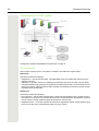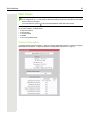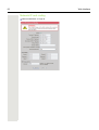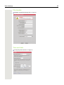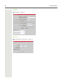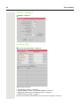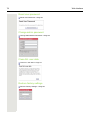
1
OpenStage 5 SIP OpenScape Voice Administration Manual A31003-S2000-M104-3-76A9 Our Quality and Environmental Management Systems are implemented according to the requirements of the ISO9001 and ISO14001 standards and are certified by an external certification company. Copyright © Unify GmbH & Co. KG 10/2014 Hofmannstr. 51, 81379 Munich/Germany All rights reserved. Reference No.: A31003-S2000-M104-3-76A9 The information provided in this document contains merely general descriptions or characteristics of performance which in case of actual use do not always apply as described or which may change as a result of further development of the products. An obligation to provide the respective characteristics shall only exist if expressly agreed in the terms of contract. Availability and technical specifications are subject to change without notice. Unify, OpenScape, OpenStage and HiPath are registered trademarks of Unify GmbH & Co. KG. All other company, brand, product and service names are trademarks or registered trademarks of their respective holders. unify.com Safety Precautions 3 Safety Precautions Important Notes 7 Do not operate the telephone in environments where there is a danger of explosions. 7 Use only original accessories. Using other accessories may be dangerous, and will invalidate the warranty and the CE mark. 7 Never open the telephone or a key module. If you encounter any problems, contact System Support. 7 Attention If the OpenStage 5 SIP is supplied with power over the LAN interface Page 127, the power source must be a limited power source PowerHub compliant with IEC 60950. • This equipment has been tested and found to comply with the limits for a Class B digital device, pursuant to Part 15 of the FCC Rules. These limits are designed to provide reasonable protection against harmful interference when the equipment is operated in a commercial environment. • This equipment generates, uses, and can radiate radio frequency energy and, if not installed and used in accordance with the instructions, may cause harmful interference to radio communications. Operation of this equipment in a residential area is likely to cause harmful interference, in which case the user will be required to correct the interference at his own expense. • The IP telephone OpenStage 5 SIP complies with the European standard EN 60 950. • The earpiece in this telephone handset contains a magnet. To prevent injury, before each use ensure objects such as pins or staples are not stuck to the earpiece. • There is always the danger of small objects being swallowed by young children. In the case of the OpenStage 5 SIP, this applies in particular to the connecting cord clip. Please make sure that such items are not accessible to children. • Never allow the telephone to come into contact with staining or corrosive liquids, such as coffee, tea, juice or soft drinks. The information provided in this document contains merely general descriptions or characteristics of performance features which in case of actual use do not always apply as described or which may change as a result of further development of the products. An obligation to provide the respective performance features only exists if expressly agreed in the terms of contract. 4 Safety Precautions Note! (for U.S.A and Canada only) This equipment has been tested and found to comply with the limits for a Class B digital device, pursuant to Part 15 of the FCC Rules. These limits are designed to provide reasonable protection against harmful interference when the equipment is operated in a residential installation. This equipment generates, uses, and can radiate radio frequency energy and, if not installed and used in accordance with the instructions, may cause harmful interference to radio communications. However, there is no guarantee that interference will not occur in a particular installation. If this equipment does cause harmful interference to radio or television reception, which can be determined by turning the equipment off and on, the user is encouraged to try to correct the interference by one or more of the following measures: • Reorient or relocate the receiving antenna. • Increase the separation between the equipment and receiver. • Connect the equipment into an outlet on a circuit different from that to which the receiver is connected. • Consult the dealer or an experienced radio/TV technician for help. This product is a UL Listed Accessory, I.T.E., in U.S.A. and Canada. Location of the Telephone • The telephone should be operated in a controlled environment with an ambient temperature between 5 °C and 40 °C (41 °F and 104 °F). • To ensure good handsfree talking quality, the area in front of the microphone (front right) should be kept clear. The optimum handsfree distance is 20 inches (50cm). • Do not install the telephone in a room where large quantities of dust accumulate; this can considerably reduce the service life of the telephone. • Do not expose the telephone to direct sunlight or any other source of heat, as this is liable to damage the electronic equipment and the plastic casing. • Do not operate the telephone in damp environments such as bathrooms. Telephone Maintenance • Always use a damp or antistatic cloth to clean the telephone. Never use a dry cloth. • If the telephone is very dirty, clean it with a diluted neutral cleaner containing some form of surfactant, such as a dish detergent. Afterwards, remove all traces of the cleaner with a damp cloth (using water only). • Never use cleaners containing alcohol, cleaners that corrode plastic, or abrasive powders. Safety Precautions 5 Labels The device conforms to the EU guideline 1999/5/EG, as attested by the CE mark. This device has been manufactured in accordance with our certified environmental management system (ISO 14001). This process ensures that energy consumption and the use of primary raw materials are kept to a minimum, thus reducing waste production. All electrical and electronic products should be disposed of separately from the municipal waste stream via designated collection facilities appointed by the government or the local authorities. The correct disposal and separate collection of your old appliance will help prevent potential negative consequences for the environment and human health. It is a precondition for reuse and recycling of used electrical and electronic equipment. For more detailed information about disposal of your old appliance, please contact your city office, waste disposal service, the shop where you purchased the product or your sales representative. The statements quoted above are only fully valid for equipment which is installed and sold in the countries of the European Union and is covered by the directive 2002/96/ EC. Countries outside the European Union may have other regulations regarding the disposal of electrical and electronic equipment. 6 Contents Contents Safety Precautions. . . . . . . . . . . . . . . . . . . . . . . . . . . . . . . . . . . 3 Important Notes. . . . . . . . . . . . . . . . . . . . . . . . . . . . . . . . . . . . . . . . . . . . . . . . . . . . . . . . . . . . . . 3 Location of the Telephone. . . . . . . . . . . . . . . . . . . . . . . . . . . . . . . . . . . . . . . . . . . . . . . . . . . . . . 4 Telephone Maintenance . . . . . . . . . . . . . . . . . . . . . . . . . . . . . . . . . . . . . . . . . . . . . . . . . . . . . . . 4 Labels . . . . . . . . . . . . . . . . . . . . . . . . . . . . . . . . . . . . . . . . . . . . . . . . . . . . . . . . . . . . . . . . . . . . . . 5 General Information . . . . . . . . . . . . . . . . . . . . . . . . . . . . . . . . . . 8 About the Manual . . . . . . . . . . . . . . . . . . . . . . . . . . . . . . . . . . . . . . . . . . . . . . . . . . . . . . . . . . . . Intended Use. . . . . . . . . . . . . . . . . . . . . . . . . . . . . . . . . . . . . . . . . . . . . . . . . . . . . . . . . . . . . . . . Product Identification. . . . . . . . . . . . . . . . . . . . . . . . . . . . . . . . . . . . . . . . . . . . . . . . . . . . . . . . . . Application Version . . . . . . . . . . . . . . . . . . . . . . . . . . . . . . . . . . . . . . . . . . . . . . . . . . . . . . . . . . . Service . . . . . . . . . . . . . . . . . . . . . . . . . . . . . . . . . . . . . . . . . . . . . . . . . . . . . . . . . . . . . . . . . . . . 8 9 9 9 9 Installation . . . . . . . . . . . . . . . . . . . . . . . . . . . . . . . . . . . . . . . . 10 Prerequisites . . . . . . . . . . . . . . . . . . . . . . . . . . . . . . . . . . . . . . . . . . . . . . . . . . . . . . . . . . . . . . . 10 Connecting to the Network . . . . . . . . . . . . . . . . . . . . . . . . . . . . . . . . . . . . . . . . . . . . . . . . . . . . 10 Installing the Phone. . . . . . . . . . . . . . . . . . . . . . . . . . . . . . . . . . . . . . . . . . . . . . . . . . . . . . . . . . 10 Power over LAN information . . . . . . . . . . . . . . . . . . . . . . . . . . . . . . . . . . . . . . . . . . . . . . . . . . . . 11 Startup Procedure . . . . . . . . . . . . . . . . . . . . . . . . . . . . . . . . . . . . . . . . . . . . . . . . . . . . . . . . . . . . 12 Using the OpenStage 5 SIP. . . . . . . . . . . . . . . . . . . . . . . . . . . 13 Dialling Keypad . . . . . . . . . . . . . . . . . . . . . . . . . . . . . . . . . . . . . . . . . . . . . . . . . . . . . . . . . . . . . 13 Programmable Keys . . . . . . . . . . . . . . . . . . . . . . . . . . . . . . . . . . . . . . . . . . . . . . . . . . . . . . . . . . 14 Control Keys . . . . . . . . . . . . . . . . . . . . . . . . . . . . . . . . . . . . . . . . . . . . . . . . . . . . . . . . . . . . . . . . 15 Phone Features . . . . . . . . . . . . . . . . . . . . . . . . . . . . . . . . . . . . 16 Protocol support . . . . . . . . . . . . . . . . . . . . . . . . . . . . . . . . . . . . . . . . . . . . . . . . . . . . . . . . . . . . Capabilities . . . . . . . . . . . . . . . . . . . . . . . . . . . . . . . . . . . . . . . . . . . . . . . . . . . . . . . . . . . . . . . . Call Features. . . . . . . . . . . . . . . . . . . . . . . . . . . . . . . . . . . . . . . . . . . . . . . . . . . . . . . . . . . . . . . DTMF . . . . . . . . . . . . . . . . . . . . . . . . . . . . . . . . . . . . . . . . . . . . . . . . . . . . . . . . . . . . . . . . . . . . 16 16 17 17 Technical Overview . . . . . . . . . . . . . . . . . . . . . . . . . . . . . . . . . 18 Session Initiation Protocol (SIP) . . . . . . . . . . . . . . . . . . . . . . . . . . . . . . . . . . . . . . . . . . . . . . . . 18 IP Network Protocols. . . . . . . . . . . . . . . . . . . . . . . . . . . . . . . . . . . . . . . . . . . . . . . . . . . . . . . . . . 22 IP Network Configuration . . . . . . . . . . . . . . . . . . . . . . . . . . . . . . . . . . . . . . . . . . . . . . . . . . . . . . 26 Administration Interfaces . . . . . . . . . . . . . . . . . . . . . . . . . . . . . 28 Web Interface . . . . . . . . . . . . . . . . . . . . . . . . . . . . . . . . . . . . . . . . . . . . . . . . . . . . . . . . . . . . . . 28 Basic Administration . . . . . . . . . . . . . . . . . . . . . . . . . . . . . . . . 29 Basic Configuration . . . . . . . . . . . . . . . . . . . . . . . . . . . . . . . . . . . . . . . . . . . . . . . . . . . . . . . . . . 29 Contents 7 Extended Administration . . . . . . . . . . . . . . . . . . . . . . . . . . . . . 35 Configure Network Parameters. . . . . . . . . . . . . . . . . . . . . . . . . . . . . . . . . . . . . . . . . . . . . . . . . 35 Configure System Information. . . . . . . . . . . . . . . . . . . . . . . . . . . . . . . . . . . . . . . . . . . . . . . . . . 37 Configuring Date and Time . . . . . . . . . . . . . . . . . . . . . . . . . . . . . . . . . . . . . . . . . . . . . . . . . . . . 40 Multiline . . . . . . . . . . . . . . . . . . . . . . . . . . . . . . . . . . . . . . . . . . . . . . . . . . . . . . . . . . . . . . . . . . . . 41 Dial Plan Configuration and Status . . . . . . . . . . . . . . . . . . . . . . . . . . . . . . . . . . . . . . . . . . . . . . 42 Direct Station Select (DSS). . . . . . . . . . . . . . . . . . . . . . . . . . . . . . . . . . . . . . . . . . . . . . . . . . . . . 43 Feature Access . . . . . . . . . . . . . . . . . . . . . . . . . . . . . . . . . . . . . . . . . . . . . . . . . . . . . . . . . . . . . . 44 Function Key assignments . . . . . . . . . . . . . . . . . . . . . . . . . . . . . . . . . . . . . . . . . . . . . . . . . . . . 44 Software Update/Transferring Files . . . . . . . . . . . . . . . . . . . . . . . . . . . . . . . . . . . . . . . . . . . . . 44 Port Numbering . . . . . . . . . . . . . . . . . . . . . . . . . . . . . . . . . . . . . . . . . . . . . . . . . . . . . . . . . . . . . . 47 Configuration Management. . . . . . . . . . . . . . . . . . . . . . . . . . . . . . . . . . . . . . . . . . . . . . . . . . . . . 48 Use SNMP . . . . . . . . . . . . . . . . . . . . . . . . . . . . . . . . . . . . . . . . . . . . . . . . . . . . . . . . . . . . . . . . 49 Change Speech Parameters. . . . . . . . . . . . . . . . . . . . . . . . . . . . . . . . . . . . . . . . . . . . . . . . . . . . 50 Configure Ringer Settings . . . . . . . . . . . . . . . . . . . . . . . . . . . . . . . . . . . . . . . . . . . . . . . . . . . . . 50 Display static Phone Information. . . . . . . . . . . . . . . . . . . . . . . . . . . . . . . . . . . . . . . . . . . . . . . . . 51 Perform Diagnostic Tests . . . . . . . . . . . . . . . . . . . . . . . . . . . . . . . . . . . . . . . . . . . . . . . . . . . . . 51 Security settings . . . . . . . . . . . . . . . . . . . . . . . . . . . . . . . . . . . . . . . . . . . . . . . . . . . . . . . . . . . . 52 Restart the OpenStage 5 SIP . . . . . . . . . . . . . . . . . . . . . . . . . . . . . . . . . . . . . . . . . . . . . . . . . . . 52 Restore Factory Settings. . . . . . . . . . . . . . . . . . . . . . . . . . . . . . . . . . . . . . . . . . . . . . . . . . . . . . . 53 Change Administrator Password. . . . . . . . . . . . . . . . . . . . . . . . . . . . . . . . . . . . . . . . . . . . . . . . 53 Reset User Password . . . . . . . . . . . . . . . . . . . . . . . . . . . . . . . . . . . . . . . . . . . . . . . . . . . . . . . . 53 Clear ALL user data . . . . . . . . . . . . . . . . . . . . . . . . . . . . . . . . . . . . . . . . . . . . . . . . . . . . . . . . . . 54 Port Control . . . . . . . . . . . . . . . . . . . . . . . . . . . . . . . . . . . . . . . . . . . . . . . . . . . . . . . . . . . . . . . . 54 Resilience and Survivability . . . . . . . . . . . . . . . . . . . . . . . . . . . . . . . . . . . . . . . . . . . . . . . . . . . 54 SIP Security Configuration . . . . . . . . . . . . . . . . . . . . . . . . . . . . . . . . . . . . . . . . . . . . . . . . . . . . . 57 Web Interface. . . . . . . . . . . . . . . . . . . . . . . . . . . . . . . . . . . . . . 59 Establishing the Connection to the Phone . . . . . . . . . . . . . . . . . . . . . . . . . . . . . . . . . . . . . . . . 59 Web Pages . . . . . . . . . . . . . . . . . . . . . . . . . . . . . . . . . . . . . . . . . . . . . . . . . . . . . . . . . . . . . . . . . 61 OpenStage 5 SIP IP number editor. . . . . . . . . . . . . . . . . . . . . . . . . . . . . . . . . . . . . . . . . . . . . . . 81 Alphabetical Reference . . . . . . . . . . . . . . . . . . . . . . . . . . . . . . 82 Description of Functions . . . . . . . . . . . . . . . . . . . . . . . . . . . . . . . . . . . . . . . . . . . . . . . . . . . . . . 82 Abbreviations and Specialized Terms. . . . . . . . . . . . . . . . . . . . . . . . . . . . . . . . . . . . . . . . . . . . 125 Troubleshooting . . . . . . . . . . . . . . . . . . . . . . . . . . . . . . . . . . . 129 General Troubleshooting Tips. . . . . . . . . . . . . . . . . . . . . . . . . . . . . . . . . . . . . . . . . . . . . . . . . 129 Fault Finding . . . . . . . . . . . . . . . . . . . . . . . . . . . . . . . . . . . . . . . . . . . . . . . . . . . . . . . . . . . . . . 129 Phone Configurations . . . . . . . . . . . . . . . . . . . . . . . . . . . . . . 133 Common Configuration (Factory Defaults ). . . . . . . . . . . . . . . . . . . . . . . . . . . . . . . . . . . . . . . 133 Product support on the internet. . . . . . . . . . . . . . . . . . . . . . . . . . . . . . . . . . . . . . . . . . . . . . . . 134 Index . . . . . . . . . . . . . . . . . . . . . . . . . . . . . . . . . . . . . . . . . . . 137 8 General Information General Information About the Manual The instructions within this manual will help you in administering and maintaining the OpenStage 5 SIP. The instructions contain important information for safe and proper operation of the OpenStage 5 SIP. Follow them carefully to avoid improper operation and get the most out of your multi-function telephone in a network environment. This guide is intended for service providers and network administrators who administer VoIP services using the OpenStage 5 SIP and who have a fundamental understanding of SIP. The tasks described in this guide are not intended for end users of the phones. Many of these tasks affect the ability of a phone to function on the network and require an understanding of IP networking and telephony concepts. For your own protection, please read the section dealing with safety. Follow the safety instructions carefully in order to avoid endangering yourself or other persons and to prevent damage to the unit. These instructions are laid out in a user-oriented manner, which means that you are led through the functions of the OpenStage 5 SIP step by step – from the setup, through descriptions of tools and extensions discussions of special administrative and service tasks at the end of the manual. For the users, a separate manual is provided. Symbols in the Manual 7 Attention This symbol indicates a hazard. Failure to follow the instructions given may result in injury or in damage to the unit. Key information important for the proper use of the unit is marked with this symbol. Shows administration tasks on the Web Interface. Shows additional information about each parameter in the Alphabetical Reference. Shows the related web pages. Means that you are in the administration menu and you have already entered the correct administrator password. (Access: Web Interface Page 60). > Means that you are in the diagnostics menu and you have already entered the correct administrator password. (Access: Web Interface Page 60). Y Means that you are in the setup menu and you have already entered the correct user password, if required. 9 General Information Operating the telephone n Lift the handset (off-hook). t Replace the handset (on-hook). s Conduct a call. o u or v Enter a telephone number or code. Increase or reduce the value depending on the current operating mode. Changing and viewing the configuration data in the phone is done by entering different reference numbers. For description of viewing data values on the LEDs of the entry see Page 81. Intended Use The OpenStage phone is a desktop unit designed for voice transmission and for connection to the LAN. It can also be used as a workstation device. Any other use is regarded as unauthorized. Product Identification The identification details of your telephone are given on the nameplate containing the exact product label and serial number on the bottom of the base unit Page 10. Please have these ready whenever you call our service department in case of trouble with or defects on the unit itself. OpenStage 5 SIP S30817-S7400-A101-1 Ser.-Nr.: 0001E320C244 E3/ Application Version To find out the current application version of your OpenStage 5 SIP see Page 51. Service The Unify service department can only help you with problems or defects on the telephone unit itself. Should you have any questions regarding the operation, your specialist retailer or network administrator will gladly help you. For any questions regarding the telephone connection, please contact your network provider. In the case of any trouble or defects on the telephone unit itself, please dial the service number of your local distributor or your local Unify Branch office. 10 Installation Installation Prerequisites The OpenStage 5 SIP acts as an endpoint client on an IP telephony network, and has the following network requirements: • An Ethernet connection to a network with SIP clients and servers (required). • A Dynamic Host Configuration Protocol (DHCP) server (optional). • Either a Call Control System – Proxy server — There must be a device running RFC 3261 SIP-compliant software. – Voice packet gateway (optional) — Required if your VOIP Network is connected to the Public Switched Telephone Network (PSTN). • or a voice packet gateway if the phone is used in gateway routing mode Page 116. Connecting to the Network You have to connect the OpenStage 5 SIP first to the LAN and then to the power supply. The OpenStage 5 SIP has one RJ-45 port labelled “10/100 LAN” The port supports 10/100 Mbps half- or full-duplex connections. We recommend that you use the port setting "Auto" Page 100 on the port for auto detection of transferring speed and type of connected cable (either straight-through or crossed). Installing the Phone Connectors on the bottom of the telephone 1 3 2 OpenStage 5 SIP 1 Ethernet port for LAN connection (optional with PoL1) 2 Handset connector 3 1 Connector for a local power supply unit (optional1) Power over LAN: If power is supplied over the LAN cable, no local power supply is required. 11 Installation Starting up the OpenStage 5 SIP The OpenStage 5 SIP phone is to connect to a Switch. The phone is working also on a Hub, but without a guarantee of quality. The Western plugs of all cable connections must audibly snap into place. • Plug the short end of the handset cable into the handset and the other end into the connector 2 at the bottom of the telephone and feed the cable through the guide channel in the base unit. Only if power not supported by LAN: 7 Use only the plug-in power supply unit fitting the OpenStage 5 SIP: – – – – EU: S30122-H7722-X UK: S30122-H7723-X USA: S30122-H7724-X IM: S30122-H7726-X See also: http://wiki.unify.com/wiki/Power_supply_and_PoE_classes. – Plug the plug-in power supply unit into the mains. – Plug the connector 3 at the bottom of the telephone into the plug-in power supply unit. • Plug the jack of the LAN cable into the connector 1 at the bottom of the telephone and connect the cable with LAN. • Feed the cables through the relief on the back of the housing and fix them by means of the cable clip. Power over LAN information Power over LAN support is provided on the LAN port and complies with the IEEE802.3af standard. 8 wire Ethernet cables are required to use it. 12 Installation Startup Procedure Start Power on Reboot see http://wiki.unify.com/ Key 3 pressed? Ye Netboot request Successful? Yes Netboot Upgrade No Application is starting Run-up and wait 120 s No DHCP activated? Run-up and wait 120 s No Yes VLAN Discovery and L2 activated? No No Using manual configuration L2 activated? Yes Ye DHCP Discover in untagged LAN No No DHCP success- Yes No No VLAN ID in Option No DHCP Discover in untagged LAN Yes DHCP Discover in VLAN Successful? Successful? Yes Yes Registration DHCP Discover in tagged LAN 13 Using the OpenStage 5 SIP Using the OpenStage 5 SIP Speaker for ring tones Keys for telephone settings Handset LEDs Key field – Eight freely programmable keys Keypad Telephone Modes Your administrator can configure the OpenStage 5 SIP for use as: • A SingleLine phone with one line. • A MultiLine phone with up to 8 lines (in relation with the SIP server). Dialling Keypad The dialling keypad of the OpenStage 5 SIP is labeled with digits, letters and some special characters. Generally you use the keypad to dial numbers. 14 Using the OpenStage 5 SIP Programmable Keys The OpenStage 5 SIP is equipped with function keys which are user-programmable in two levels (see User Manual). These keys come already preassigned in the first level Mute 1 Loudspeaker 2 Voice Message 3 Cancel/Release 4 Confirm 5 Blind Transfer 6 Hold 7 Shift 8 Function Key 1 2 3 4 5 6 7 8 Function Switches the handset microphone on/off Switches the loudspeaker on/off Indicates and starts voice messages Cancels an active call/latest activity Confirms input made Transfers a call without announcement Holds a call explicitly Toggles between first and second key levels 15 Using the OpenStage 5 SIP Control Keys The two control keys v and u are located on the left side of the dialling keypad. Depending on the operating mode, you can vary the following settings: Operating mode Receiving a call v key u key Reduce the volume of the Increase the volume of the ringer ringer tone tone Open listening Reduce the volume of the Increase the volume of the loudloudspeaker speaker Using the handset of the tele- Reduce the volume of the Increase the volume of the handhandset loudspeaker phone set loudspeaker Permanent audio settings Adjust loudspeaker volume, ringer volume and handset volume confirmed by key Confirm Restart and factory setting Starts these functions 16 Phone Features Phone Features Protocol support The OpenStage 5 SIP supports the following protocols: • • • • • • • • • • • • SIP (RFC 3261 compliance) SDP TCP/ UDP FTP SNMP SNTP HTTP RTP/ RTCP DNS DHCP EAP (802.1X) Quality of service in accordance with DiffServe and IEEE 802.1p/q. Capabilities The OpenStage 5 SIP supports the following capabilities: Network • • • • • Power over LAN DHCP for automatic IP address assignment or static IP configuration SNTP for automatic time synchronization Support for VLANs Support for configurable Layer 2 and 3 Quality of Service Configuration • • • • Country definition allowing flexible tone generation Feature enable/disable User and administrator levels (password protected) Upload and download of configuration files (INI file format) Management • Deployment service (DLS) for configuring phones • Web interface for configuring individual phones • SNMP Speech • • • • Support for G711 (U and A Law), G723 and G729 High Quality speaker phone functionality G711 Silence Suppression Audio codec G.722 offers a wider audio bandwidth resulting in major improvement in the represented speech quality. 17 Phone Features Call Features • • • • • • • • • • • Call forwarding (Unconditional, On Busy, On no Reply)1 Call waiting Consultation Unattended Transfer Attended Transfer (Join) Do not Disturb Hold Message Waiting MultiLine Call back[1] More features available with server related access code DTMF The phone provides 2 mechanisms for transmitting DTMF information, inband and DTMF in RTP (see RFC 2833). The phone does not support outband DTMF through SIP messaging. There are no configuration parameters on the phone which control the use of DTMF. A process of negotiation is used during call-setup to determine which form of DTMF signaling will be used. The phone supports send DTMF information in response to the user pressing the keys 0-9 and * and # when in a call connected state. When a call is made from a phone it will "Offer" the remote endpoint support for DTMF in RTP (this is carried in the SDP protocol). If the far end does not "answer" that it can support DTMF in RTP then DTMF in-band will be used otherwise DTMF in RTP will be used. When DTMF in RTP is negotiated the phone will always "offer" payload 100 to carry the DTMF events. The far end may accept and confirm this payload or it may suggest a different payload value. In this case the phone will follow that payload preferred by the far end. On an incoming call the phone will follow the payload value suggested by the far end. The phone is not capable of retrieving or understanding DTMF in-band or DTMF in RTP information it may receive. This information is normally used by application or media servers to control feature access. If the user presses keys when in a call connected state and in-band DTMF has been negotiated he will hear the tones being sent in the speech path (handset only). If DTMF in RTP has been negotiated he will here clicks as speech packets are removed and replaced with DTMF in RTP key events. See also Page 108. 1. Server based feature, (de)activated by access codes 18 Technical Overview Technical Overview Session Initiation Protocol (SIP) Overview The Session Initiation Protocol (SIP) is a ASCII-based signalling protocol used for establishing sessions in an IP network. A session could be a simple two-way telephone call or it could be a collaborative multi-media conference session. Like other VoIP protocols, SIP provides signaling and session management within a packet telephony network. Signaling allows call information to be carried across network boundaries. Session management controls the attributes of an end-to-end call. SIP was originally developed in the MMUSIC group within the IETF (Internet Engineering Task Force), it has been published since February 1999 as RFC 2543. The SIP working group is continuing to enhance the protocol and published version 2 as RFC 3261 in 2002. SIP Functions Systems which use SIP are able to provide the following: • The location of the target endpoint — SIP supports address resolution, name mapping, and call redirection. • The media capabilities of the target endpoint—Via Session Description Protocol (SDP), SIP determines the lowest level of common services between endpoints. Conferences are established using only the media capabilities that can be supported by all endpoints. • A session between the originating and target endpoint — If the call can be completed, SIP establishes a session between the endpoints. SIP also supports mid-call changes such as adding another endpoint to the conference and changing media characteristic or codec. 19 Technical Overview Components in a SIP system Configuration example with additional components Page 20 SIP Components SIP is a peer-to-peer protocol. The peers in a session are called user agents (UAs). SIP Clients SIP clients include the following: • Telephones — Act as UAS and UAC. The OpenStage 5 SIP can initiate SIP requests and respond to requests. • Gateways — Provide call control. Gateways provide many services, the most common being translation between SIP conferencing endpoints of transmission format, communications procedures, and codecs. Other functions include call setup and clearing on both the LAN side and the switched-circuit network side. SIP Servers SIP servers include the following: • Proxy servers — Receive SIP requests from a client and forward them to the next SIP server in the network. Proxy servers can provide functions such as authentication, authorization, network access control, routing, reliable request retransmission, and security. • Registrar servers — Process requests from UACs for registration of their current location. Registrar servers are often colocated with redirect or proxy servers. 20 Technical Overview Additional Components • DHCP server Distributes IP data and further information in a network automatically (list of distributed information Page 89). • SNTP server Provides time, date, daylight saving and timezone information. • Messaging server For recording and reading messages. • SNMP server Logging and maintenance of network components. • FTP server For up- and download of files from and to the phone. These include configuration files and music files. • PC with internet browser Enables the administration of the phone by using a Web Client such as Internet Explorer. Registration Note that registration only occurs when the SIP Routing mode Page 116 is set to "Server". Registration is the process by which centralized SIP Server/Registrars become aware of the existence and readiness of an endpoint to make and receive calls. The phone supports a number of configuration parameters to allow this to happen. Registration can be authenticated or un-authenticated depending on how the server and phone is configured. For unauthenticated registration the following parameters must be set on the phone: • Terminal number Page 121 or Terminal name Page 121. • SIP Routing Page 116 set to "Server". • SIP Server/Registrar address Page 114 configured (IP address or host name). In this mode the server must pre-authenticate the user. This procedure is server specific and is not described here. The phone supports the Digest authentication scheme and requires the following parameters to be configured in addition to those for unauthenticated registration: • SIP user ID Page 117. • SIP Password Page 115. • SIP Realm (optional) Page 115. For authentication to work the server must have created an account for the user with matching user ID, password and Realm parameters. Note a challenge from the server for authentication information is not only restricted to the REGISTER message but can also occur in response to other SIP messages eg INVITE. Below are some specific details relating to SIP registration configuration parameters found on the phone: • • • • • • • Terminal Number Page 121 Terminal Name Page 121 Register by Name Page 111 SIP Routing Page 116 SIP Registrar (SIP Addresses) Page 114 SIP Realm Page 115 Registration Timer Page 112 21 Technical Overview If a registration attempt should result in a timeout. The phone waits a random time before sending another REGISTER message. The Reg. backoff (seconds) parameter determines the maximum waiting time. 22 Technical Overview IP Network Protocols DHCP The Phone contains a Dynamic Host Configuration Protocol (DHCP) client that supports automatic configuration of various parameters. If DHCP is enabled in the phone, the phone will try to obtain the following options that are essential for the configuration of its Ethernet interface automatically from a DHCP server: • Terminal IP Address • Terminal Mask (Network Mask) When the telephone requests its IP address, it sends – apart from other information – its default host name to the DHCP server. The default host name consists of telephone model + type + MAC address (e.g. OST5D0001e325a845). The DHCP server forwards this name to the DNS server, together with the IP address assigned. If the phone fails to configure its Ethernet interface from a DHCP server it will eventually time-out indicating no DHCP server found and imminent restart. Other configuration options that the phone attempts to retrieve from the DHCP server include: • • • • • • • • Default Route (Routers option 3) IP Routing/Route 1 & 2 (Static Routes option 33) SNTP IP Address (NTP Server option 42) Timezone offset (Time Server Offset option 2) Primary/Secondary DNS IP Addresses (DNS Server option 6) DNS Domain Name (DNS Domain option 15) SIP Addresses / SIP Server & Registrar (SIP Server option 120) Vendor Unique (option 43 Page 23) These parameters are not essential to basic network configuration the operation of the phone and if not obtained will not cause a reboot. The phone assumes these parameters are not provided by DHCP until they are returned from the DHCP server. If these parameters are returned from the DHCP server they are used and not editable in the various phone menus. If these parameters cannot be obtained from the DHCP server the manually configured settings for these options are used. SIP Server option 120: Because the phone only reads the first name/IP address supplied in option 120, the maximum length of the contents has been limited to 50 octets. Please be aware of this when you are using it. VLAN discovery per DHCP An additional use for DHCP in the phone is the VLAN discovery per DHCP feature. This allows the phone to discover its VLAN from a DHCP server in the untagged LAN. After discovering its VLAN the phone starts its standard DHCP process within that discovered VLAN to configure itself from the DHCP within that VLAN. Technical Overview 23 DHCP Support Explanation of Option 43 As no DHCP option exists for the exchange of VLAN information over DHCP, the Vendor Specific Information option (43) shall be used to encapsulate VLAN and download configuration. The following diagram illustrates the format of the Vendor Specific Option. 10 ’S’ ’i’ ’e’ ’m’ ’e’ ’n’ ’s’ 0 0 0 2 4 Option 2 data to be allocated VID 0 0 0 0 0 0 0 Code Length Option 1 data - "Siemens" identifier Padding 10 11 12 13 14 15 16 17 18 19 20 21 22 23 24 25 Padding 9 Padding 8 Padding 7 Padding 6 VID LO 5 VID HI 4 Code Value 43 20 1 3 Length 2 Code 1 Length Code Byte 0 # Descrip tion 255 Byte 1 contains the tag "43", option 1 data contains the "Siemens" identifier and the VLAN ID is contained in option 2. Five Padding Bytes starting in Byte 20 and the terminate option 255 in byte 25 complete the option frame. If you have to specify a configuration download server for configuration update ( see Page 48) so you have to add the values of the server. You can place the new option before or after the VLAN information but the five Padding Bytes (Value 0) and the terminate option 255 have to close the option frame. Example: Code: 4 length: 28 data: sdlp://dls.siemens.com:18443 Code Length Padding Padding Padding Padding Padding Code 2 2 2 2 2 2 2 2 2 2 3 3 3 3 3 3 3 3 3 3 4 4 4 4 4 4 4 4 4 4 5 5 5 5 5 55 0 1 2 3 4 5 6 7 8 9 0 1 2 3 4 5 6 7 8 9 0 1 2 3 4 5 6 7 8 9 0 1 2 3 4 Option 1 data - "dls server address" 3 2 ’s ’d ’l’ ’p ’:’ ’/’ ’/’ ’d ’l’ ’s ’.’ ’s ’i’ ’e’ ’ ’e ’n’ ’s’ ’.’ ’c ’o’ ’ ’:’ ’1’ ’8’ ’4’ ’4’ ’3’ 0 0 0 0 0 25 8 ’ ’ ’ ’ ’ ’ m ’ ’ m 5 ’ ’ The five Padding Bytes and the terminate option 255 now completes the option frame in byte 48. Using Vendor Classes A "Vendor Class" is used to make sure that vendor-related information is only sent to the telephones (instead of sending it to all other terminal devices as well). By using a vendor class, vendor information elements for each vendor class can be sent to all devices of this vendor class. The vendor class name is "OptiIpPhone". OpenStage 5 SIP telephones send their vendor class name using the option 60 to the DHCP server whenever they request data from the DHCP server. If the option "VLAN Discovery" is set to DHCP on the telephone, the telephone registers using the vendor class name "OptiIpPhone" during the initial boot process, and then using the vendor class name "OptiIpPhone". On the DHCP server, you can therefore use the vendor class name "OpenStage 5 SIP" to assign the VLAN, and use the vendor class name "OptilpPhone" to assign the DLS server address or the name. This enables a more specific configuration of the DHCP server. The Authentication is done via digital Certificates. For detailed informationen refer to the IEEE 802.1x Configuration Management Administration Guide. 24 Technical Overview DNS The phone uses DNS services provided the phones operating system to perform the following: • Resolve the IP address of servers that have been configured as names (DNS A,AAAA records). • Resolve the IP address of the domain part of users called by URL (DNS A,AAAA records). • Identify the location of servers and provide for failover and load balancing (DNS A, AAAA and DNS SRV). For DNS services to be used on the phone the following must be configured either manually or provided by DHCP: • DNS Domain Name Page 94 • Prim DNS IP addr Page 108 • Sec DNS IP addr Page 113 If a DNS Domain Name and one or both of the DNS IP addresses have been configured, then additionally the following host names can be entered alternatively to the corresponding IP addresses: • SIP addresses Page 114 (server, gateway, registrar) • Download server IP address or DNS name Page 94 • SNMP Trap IP address or DNS name Page 118 • SNTP server address or DNS name Page 118 • Message Waiting IP address Page 105 • Ping Page 108 The Primary DNS server IP address must be configured if DNS is to be used however the secondary server is optional. The purpose of the secondary server is to allow a backup DNS server to be used in the system environment to increase system availability and reliability. The phone can contact several types of server for different reasons (SNTP, SNMP, SIP server etc). If a server has been configured by name and not IP address the phone will provide a DNS lookup to resolve the name to an IP address when the server needs to be contacted. To optimize network traffic performance the phone caches the result of the normal A and AAAA record lookups and will not re-issue a request to the DNS server to resolve that address again until the Time To Live value from the previous lookup has expired. If a secondary DNS server has been configured and the primary fails to respond to a request, that request will be re-issued to the secondary DNS server. DNS SRV The phone supports the use of DNS SRV record lookups to allow SIP servers to be located. This mechanism is described in detail in RFC 3263 - Locating SIP Servers. If the location to which a SIP message is to be sent is defined as a name as opposed to an IP address a DNS SRV lookup will be performed. An example query being: _sip._tcp.example.com. This indicates a query for a SIP server supporting the TCP transport protocol. The transport used in this query is determined by the SIP transport menu setting Page 117. The DNS server may return an IP address for the requested SIP server or may return a single name or list of names which require further A or AAAA record lookups to determine an IP address. The response to a DNS SRV query will also contain information regarding the Time To Live for the information returned, the port address to which requests should be sent and weighting information relating to load balancing of requests. Technical Overview 25 DNS SRV and failover Lists of candidate SIP server names are often returned in response to DNS SRV queries to allow failover mechanisms to be implemented which increase overall system availability. If the phone sends a request to the first address in the list but fails to receive a response (the failover time is configurable – default is 32 seconds – see also Page 122) the address is placed in a "penalty box" which means that it will not be tried again until a specific time interval has past (currently pre-set to 10 minutes). The request is sent to the next SIP server in the list and the process continues. The penalty box mechanism ensures that the responsiveness of the phone is maintained by not continually retrying SIP servers that are failing to respond. For example the request to the first SIP server in the list fails, a call to another user hosted on the SIP server will result in the user experiencing a 6 second delay before the failover to the secondary occurs. All subsequent messages for this call will go to the second SIP server until the first SIP server is removed from the penalty box and it can be tried once again to see if it is back in service. Note this mechanism is independent of call setup. The first SIP server will not be retried necessarily when the next call is established, only when it is removed from the penalty box. SNTP The phone support SNTP. The SNTP server address can be supplied via DHCP or manually configured Page 118. If the SNTP server address is available the server will be queried for the time. If a server address is not configured the phone will look for SNTP broadcasts and setup the time accordingly, if these are received any manually configured time and date information would be over written. SNMP The phone provides SNMP which allows network related information to be browsed (MIB II support). Standard SNMP browsers are sufficient for this purpose. 26 Technical Overview IP Network Configuration Routing The phone allows a default route to be configured to allow access to Servers on a different subnet to the one in which the phone resides. In addition it is possible to configure 2 additional routes. Each route consists of a IP address, gateway and mask. Virtual LAN (VLAN) VLAN or virtual LAN is a technology that allows network administrators to partition one physical network into a set of virtual networks (or broadcast domains). Physically partitioning the LAN into separate VLANs allows a network administrator to build a more robust network infrastructure. A good example is of the data and voice networks being partitioned into data and voice VLANs. This isolates the two networks and helps shield the endpoints within the voice network from disturbances in the data network and vice versa. VLAN is a layer 2 (Physical Layer) protocol. In the case of Ethernet the physical header is extended allowing endpoints to be not only be addressed via MAC address, but also VLAN ID Page 105. Ethernet VLANs support the partitioning of a physical LAN into up to 4095 virtual LANs. To implement a voice network based on VLANs requires the network infrastructure (the switch fabric) to support VLANs at layer 2. Dependant on the overall architecture it may or may not be necessary for the endpoint (phone) to support layer 2 VLAN. The ports of the network switches in the switch fabric can be logically grouped as ports belonging to particular VLAN. The switch only forwards traffic to a particular port if that port is a member of the VLAN that the traffic is allocated to. In this way an endpoint connected to a particular port on the switch is automatically a member of that VLAN without being a VLAN aware device; the switch ensures the endpoint only receives traffic for that VLAN and ensures traffic from the endpoint is only forwarded to ports that are configured to be in the same VLAN. This is known as port based VLAN in the switch world. VLAN support The phone can be configured as a VLAN aware endpoint by enabling VLAN support via the configuration menus. The following VLAN related configurations can be achieved: • Manually configured L2 VLAN only. • Manually configured L2 VLAN and QoS. • Automatically discovered VLAN and manual QoS. To configure manual L2 VLAN only the phone must be configured at manual VLAN ID between 1 and 4095. Vlan discovery mode must be set to manual. To configure manual L2 VLAN and QoS the phone must be configured as QoS layer 2 on and a manual VLAN id between 1 and 4095. Vlan discovery mode should be set to manual and QoS layer 2 and 3 values should be configured as described in the QoS section below. If you mis-configure a phone to an incorrect VLAN the phone will behave as though it is not configured for and possibly not connected to the network. In DHCP mode it will behave as though the DHCP server cannot be found, in fixed IP mode no server connections will be possible. To automatically discover a VLAN ID using DHCP the phone must be configured as DHCP enabled and VLAN discovery mode set to DHCP. If QoS is required this can be turned on and QoS layer 2 and 3 values should be configured as described in the QoS section below. Technical Overview 27 The DHCP server must be configured to supply the Vendor Unique Option in the correct Unify VLAN over DHCP format. If a phone configured for Vlan discovery by DHCP fails to discover its VLAN it will proceed to configure itself from the DHCP within the non-tagged LAN. In these circumstances network routing will probably not be correct; the SIP server may or may not be reached. The default setting for the phone is to try and perform VLAN discovery. DLS The Deployment Service (DLS) is a OpenScape Management application for administering workpoints (optiPoint, OpenStage telephones and optiClient installations) in OpenScape Voice networks. It has a Java-supported, web-based unser interface, which runs on an internet browser. Amongst the most important features are: security (e.g. PSS generation and distribution within an SRTP security domain), software deployment, plug&play support, as well as error and activity logging. For detailed informationen about DLS refer to the OpenScape Voice Deployment Service Administration Manual. The Authentication is done via digital Certificates. For detailed informationen refer to the IEEE 802.1x Configuration Management Administration Manual. Quality of Service (QoS) Modern networks can be used to provide various Qualities of Service to network endpoints based upon the importance of the endpoint and its generated traffic. Quality of Service is a term used to describe this catagorisation of network traffic in networks based on the importance of the data and the treatment of that prioritized traffic. A typical example of use of QoS in a network is that of an IP Phone. Telephone Voice traffic is more important that for HTTP related traffic for a PC. Prioritization of voice traffic over that of the HTTP traffic means that during periods of heavy network load that voice service is maintained, whereas the response times for a user's Web Broweser will degrade and possibly stop working. Quality of Service can be supported in networks at both Layer 2 and Layer 3. At Ethernet layer 2 the MAC header is extended to provide VLAN information and Quality of Service priorities. Ethernet layer 2 allows for prioritisation of traffic from 0 (lowest) to 7 (highest). At the layer 3, the IP layer traffic can be prioritized using information embedded in the IP Type of service (DiffServ) field that allows for 64 levels of prioritization. To utilize Quality of Service features the network infrastructure (switch fabric) must support prioritized delivery of traffic based on layer 3 and/or layer 2. Secure Payload OpenStage 5 SIP telephones enable you to establish a secure telephone connection, provided that the recipient’s telephone is also capable of this. Voice transmission is encrypted and subsequently decrypted by the called party’s telephone and vice versa. Even the signaling for the callsetup and the exchange of the encryption data is carried out via a secure connection. The telephones have to have a valid registration at an SIP server via TLS. 28 Administration Interfaces Administration Interfaces You can configure the OpenStage 5 SIP by using any of the following methods. Web Interface For remote configuration of individual IP phones in your network. Direct access to the phone is not required. Menu overview see Page 60. To use this method, the phone must first obtain IP connectivity. The remote configuration is not applicable while the phone is not in idle mode. Basic Administration 29 Basic Administration The phone is factory preconfigured to allow for a minimum of configuration activites required on the unit itself. A number of parameters can be configured centrally by using a DHCP server. When the phone is connected to the network it will react as follows: • If your network use a DHCP server, the telephone will try to get its IP Address, IP Address Mask, SIP Addresses (server, gateway, registrar), SNTP Server Address Configuration Download Server Address and Time Offset from the DHCP server (completely list see Page 22). In this case the telephone will boot with the IP address and will get the exact time from the configured SNTP server. You only have to configure the Terminal number, SIP user ID and password . Page 63 • If the DHCP server is not available or configured to provide these parameters, the telephone will become idle and has to be manually configured Page 30. Basic Configuration Configuration using DHCP Server The OpenStage 5 SIP is factory-configured to have an IP address automatically assigned to it by the DHCP server as soon as it’s connected to LAN. The Authentication is done via digital Certificates. For detailed informationen refer to the IEEE 802.1x Configuration Management Administration Manual. If your network use a DHCP server, the telephone will try to get its IP Address, IP Address Mask, SIP Addresses (server, gateway, registrar), SNTP Server Address Configuration Download Server Address and Time Offset from the DHCP server (completely list see Page 22). In this case the following parameters have to be configured using the Web Interface Administrator Menu. Parameter Terminal Number Page 121 SIP User ID Page 117 SIP Password Page 115 Web Interface path (Menu Page 60) - SIP environment - Terminal number (enter terminal number) - SIP environment - SIP user ID (enter ID) - SIP environment - New/Confirm SIP password (enter/re-enter password) 30 Basic Administration Manual Configuration If your network does not use a DHCP server, you must disable the DHCP IP assignment manually and specify the phone’s IP address and subnet mask and the network gateway IP address (default route) for the phone. Entering the administration area edg Press the keys simultaneously or vuqj Press the keys successively. (all LEDs flash). o Enter admin password (default: 123456). r Terminate the operation. You are now in the Administration Area The top two function keys take over the following functions in this area: 1st Function key Press 1st function key to make settings. <PROG> 2nd Function key Press 2nd function key to view settings (results ASCII codes see Page 81). <VIEW> Configure basics Press 1st function key. <PROG> dd Enter code d Switch the DHCP IP assign off. r Terminate the operation. <PROG> de o r <PROG> df o r <PROG> dg o r Press 1st function key. Enter code. Enter IP address of the OpenStage 5 SIP (to edit see Page 81). Terminate the operation. Press 1st function key. Enter code. Enter terminal mask of the OpenStage 5 SIP (to edit Page 81). Terminate the operation. Press 1st function key.. Enter code. Enter the default Route of the OpenStage 5 SIP (to edit see Page 81). Terminate the operation. Basic Administration 31 Only if you are working in a Virtual LAN (VLAN): Press 1st function key. <PROG> fid r <PROG> fh o r Input the code to define the manual configuration of the VLAN Discovery Mode. Terminate the operation. Press 1st function key. Enter code. Enter (0 - 4095) for the Virtual LAN ID. Terminate the operation. Confirm your entries and start the telephone: Press key. <PROG> mm r Enter the code. Confirm the entry. After restart, you can make the other settings. Other settings All other settings of your OpenStage 5 SIP must be made through the "Webbased Management Tool" Page 59. Example 1: enter the IP address 192.168.1.44 To enter the ASCII code of the IP address follow the steps below: vuqj Press the keys successively. (all LEDs flash). o Enter admin password (default: 123456). r Terminate the operation. You are now in the Administration Area Press 1st function key to make settings. <PROG> de Enter code for IP address. ge Enter character "1" gm Enter character "9" gf Enter character "2" q Enter character dot ge Enter character "1" gl Enter character "8" gj Enter character "6" q Enter character dot ge Enter character "1" 32 Basic Administration q Enter character dot gh Enter character "4" gh Enter character "4" r Terminate the operation. If this is the last operation at all, don’t forget to confirm your entries and restart the telefon (see page before) Example 2: Check the IP address If you want to do other settings through the "Web-based Management Tool" you have to know the current IP address. To find out the address in binary code follow the steps below: vuqj Press the keys successively. (all LEDs flash). o Enter admin password (default: 123456). r Terminate the operation. You are now in the Administration Area Press 2nd function key to view settings (results ASCII codes see Page 81). <VIEW> de Enter code for IP address. r Step to the first character Upper Byte shows 3 (the first 4 LEDs) Lower Byte shows 1 (the second 4 LEDs) r Step to the next character Upper Byte shows 3 (the first 4 LEDs) Lower Byte shows 1 (the second 4 LEDs) r Step to the next character Upper Byte shows 3 (the first 4 LEDs) Lower Byte shows 2 (the second 4 LEDs) r Step to the next character Upper Byte shows 2 (the first 4 LEDs) Lower Byte shows E (the second 4 LEDs) r Step to the first character Upper Byte shows 3 (the first 4 LEDs) Lower Byte shows 1 (the second 4 LEDs) r Step to the first character Upper Byte shows 3 (the first 4 LEDs) Lower Byte shows 8 (the second 4 LEDs) r Step to the first character Upper Byte shows 3 (the first 4 LEDs) Lower Byte shows 6 (the second 4 LEDs) r Step to the next character Upper Byte shows 2 (the first 4 LEDs) Lower Byte shows E (the second 4 LEDs) r Step to the next character Upper Byte shows 3 (the first 4 LEDs) Lower Byte shows 1 (the second 4 LEDs) Basic Administration 33 r Step to the next character Upper Byte shows 2 (the first 4 LEDs) Lower Byte shows E (the second 4 LEDs) r Step to the next character Upper Byte shows 3 (the first 4 LEDs) Lower Byte shows 4 (the second 4 LEDs) r Step to the next character Upper Byte shows 3 (the first 4 LEDs) Lower Byte shows 4 (the second 4 LEDs) r Step to the next character All LEDs are off. The IP address is complete and the operation has finished. 34 Basic Administration After reboot the following parameters have to be configured: Parameter Terminal Number Page 121 SIP User ID Page 117 SIP Password Page 115 SIP Server Address Page 114 SIP Registrar Address Page 114 SIP Routing Page 116 Web Interface path (Menu Page 60) - SIP environment - Terminal number (enter terminal number) - SIP environment - SIP user ID (enter ID) - SIP environment - New/Confirm SIP password (enter/re-enter password) - SIP environment - Server IP address (enter IP address*) - SIP environment - Registrar IP address (enter IP address*) - SIP environment - SIP routing (select routing) Extended Administration 35 Extended Administration Configure Network Parameters To access a SIP server as an IP client some network related information have to be configured. Depending on the SIP network environment different changes are necessary Page 29. Network Addresses Parameter DHCP IP Assignment Page 89 Terminal IP Address Page 121 Terminal Mask Page 121 Default Route (Gateway) Page 89 IP Route 1/2 (IP address/Gateway/Mask) Page 99 DNS Domain Name Page 94 Primary DNS IP Address Page 108 Secondary DNS IP Address Page 113 Terminal hostname Page 120 Use dynamic hostname Page 123 NAT keep alive Page 105 Web Interface path (Menu Page 60) - Network IP and routing - DHCP (activate/deactivate checkbox) - Network IP and routing - Terminal IP address (enter IP address) - Network IP and routing - Terminal mask (enter terminal mask) - Network IP and routing - Default gateway (enter gateway address) - Network IP and routing - IP routing (Route 1/2) - Route (enter IP address) - Gateway (enter IP address) - Mask (enter subnet mask) - Network IP and routing - Domain name (enter domain name) - Network IP and routing - Primary DNS IP address (enter IP address) - Network IP and routing - Secondary DNS IP address (enter IP address) - Network IP and routing - Terminal hostname (change name) - Network IP and routing - Use dynamic hostname concept (mark to enable/disable)) - Network IP and routing - NAT keep alive (range 10 to 3600) Changing either the DHCP IP assignment or the Terminal IP address will take effect as soon as the OpenStage 5 SIP is restarted. 36 Extended Administration Quality of Service (QoS) By changing the Quality of Service parameter you can affect the speech quality results. Further speech quality parameters see Page 50. QoS Configuration Parameter QoS Mode Page 109 Layer 3 Voice (only if L3On) Page 99 Layer 3 Signalling (only if L3On) Page 99 Layer 2 Voice (only if L2On) Page 100 Layer 2 Signalling (only if L2On) Page 100 Layer 2 Default (only if L2On) Page 100 Web Interface path (Menu Page 60) - Quality of Service - Required (select QoS mode) - Quality of Service - Layer 3 Voice (select Layer 3 Voice value) - Quality of Service - Layer 3 Signalling (select Layer 3 Signalling value) - Quality of Service - Layer 2 Voice (enter Layer 2 Voice value) - Quality of Service - Layer 2 Signalling (enter Layer 2 Signalling value) - Quality of Service - Default (enter Default value) Changing any QoS settings will take effect as soon as the OpenStage 5 SIP is restarted. VLAN Settings Parameter Manual VLAN Identifier Page 105 VLAN Discovery Method Page 124 Web Interface path (Menu Page 60) - Quality of Service - Manual vLAN identifier (enter VLAN ID) - Quality of Service - vLAN discovery method (select VLAN discovery) Changing the VLAN Discovery Method will take effect as soon as the OpenStage 5 SIP is restarted. Extended Administration 37 LAN Port Settings Parameter Web Interface path (Menu Page 60) LAN Port Setting Page 100 - LAN Port Settings (select speed for port 1(LAN)) Configure System Information To be granted access to a SIP Server some terminal and SIP related information have to be configured. First of this the SIP server has to be configured. Terminal Details Parameter Terminal Number Page 121 Terminal Name Page 121 Register by Name Page 111 Web Interface path (Menu Page 60) - SIP environment - Phone number (enter terminal number) - SIP environment - Phone name (enter terminal name) - SIP environment - Register by name (activate/deactivate checkbox) 38 Extended Administration SIP Specific Configuration Parameter SIP Routing Page 116 Outbound Proxy Page 107 Default OBP Domain Name Page 89 SIP Server Address Page 114 SIP Registrar Address Page 114 SIP Gateway Address Page 114 SIP Phone Port Page 114 SIP Transport Page 117 SIP server type Page 116 SIP Realm Page 115 SIP User ID Page 117 SIP Password Page 115 SIP Session Timer Page 117 SIP Session Time Page 116 Registration Timer Page 112 Transaction timer Page 122 Registration backoff timer Page 111 Web Interface path (Menu Page 60) - SIP environment - SIP routing (select routing) - SIP environment - Outbound Proxy (activate/deactivate checkbox) - SIP environment - Default domain name (enter domain name) - SIP environment - Server IP address or DNS name (enter IP address) - SIP environment - Registrar IP address or DNS name (enter IP address) - SIP environment - Gateway IP address or DNS name (enter IP address) - SIP environment - SIP Port - RTP Base Port (enter Port addresses) - SIP environment - SIP transport (select transport) - SIP environment - SIP server type (select type) - SIP environment - SIP realm (enter realm name) - SIP environment - SIP user ID (enter ID) - SIP environment - New/Confirm SIP password (enter/re-enter password) - SIP environment - SIP session timer enabled (activate/deactivate checkbox) - SIP environment - SIP session timer value (enter time) - SIP environment - Registration timer value (enter time) - SIP environment - Transaction Timer (enter time) - SIP environment - Registration backoff timer (enter time) Extended Administration 39 Changing either the Terminal Number or the SIP Routing setting will take effect as soon as the OpenStage 5 SIP is restarted. SIP Features Parameter Call handling options Auto answer Page 115 Beep on Auto answer Page 115 Auto reconnect Page 115 Beep on Auto reconnect Page 115 Group pickup Group pickup URI Page 97 HotWarm Phone Phone type Page 98 Default dial string Page 98 Transfer on Ringing Page 123 Callback URIs Page 87 Initial Digit Timer Page 98 Web Interface path (Menu Page 60) - SIP features - Auto answer (mark to be enabled) - SIP features - Beep on Auto answerI (mark to be enabled) - SIP features - Auto reconnect (mark to be enabled) - SIP features - Beep on Auto reconnect (mark to be enabled) - SIP features - Group pickup URI (enter URI) - SIP features - Phone typeI (select type) - Default dial string (enter dial string) - SIP features - Allow transfer on ringing (mark to allow) - SIP features - Callback (enter related access code) - SIP features - Initial digit timer (set timer 1 to 120) 40 Extended Administration Miscellaneous Parameter Emergency Number Page 95 Voicemail Number1 Page 124 Message Waiting Address1 Page 105 1 Web Interface path (Menu Page 60) - SIP environment - Emergency number (enter emergency number) - SIP environment - Voicemail number (enter voicemail number) - SIP environment - Message Waiting IP Address or DNS name (enter IP address) Either the Voicemail Number or the Message Waiting Address should be entered, but not both of them. Configuring Date and Time If the DHCP server in your network provides information about the SNTP server access, the date and time is automatically shown on the phone. If the DHCP server in your network does not provide a SNTP address you have to set the SNTP address manually. If no SNTP server is in your network you have to configure the date and time manually. If SNTP is being used, any user specified value for Time and Date will be overwritten when the next SNTP update occurs! SNTP is available, but no automatic access by DHCP server Parameter SNTP Address Page 118 Timezone Offset Page 122 1 Web Interface path (Menu Page 60) - Time and date - SNTP server IP address or DNS name (enter IP address1) - Time and date - Time zone offset (enter timezone offset) or host name (if DNS is applicable Page 24) No SNTP server available Parameter Date/Time Page 88 Daylight Saving Time Page 89 Web Interface path (Menu Page 60) - Time and date - Local time/Date (enter Local time, enter/select Date) - Time and date - Daylight saving (activate/deactivate checkbox) Extended Administration 41 Multiline Line key configuration In line overview menu you can configure lines and an assign lines to keys. It suffices to assign one line to a key for to go in multiline operation. Parameter Line Page 101 Address of record Page 103 Realm Page 104 Primary line Page 104 Ring Page 104 Hunt ranking Page 103 User ID Page 104 Password Page 104 Shared type Page 103 Web Interface path (Menu Page 60) - Funcktion keys - Phone - Select a key with EDIT a configuration dialog appears - Select:line (A key with line is ready for configuring) Line key configuration dialog - Address of record (enter e.g. phone number) Line key configuration dialog - Realm (enter IP address) Line key configuration dialog - Primary line (mark as primary if required) Line key configuration dialog - Ring (enable/disable) Line key configuration dialog - Hunt ranking (select order) Line key configuration dialog - User ID (enter ID) Line key configuration dialog - Password (enter password) - Line key configuration dialog - Shared type (select type) 42 Extended Administration Configure Multiline Operation Parameter Registration LEDs Page 111 Rollover type Page 113 Rollover Volume Page 113 Originating line preference Page 106 Terminating line preference Page 122 Line action mode Page 102 Show focus Page 114 Forwarding Indication Page 96 Reservation Timer Page 112 Web Interface path (Menu Page 60) - Multiline operation - Registration LEDs (activate/deactivate checkbox) - Multiline operation - Rollover type (select rollover type) - Multiline operation - Rollover volume (select rollover volume) - Multiline operation - Originating line preference (select line preference) - Multiline operation - Terminating line preference (select line preference) - Multiline operation - Line key operation mode (select operation mode) - Multiline operation - Show focus (mark to enable) - Multiline operation - Use LED to indicate Remote Forwarding (mark to enable) - Multiline operation - Reservation timer (set time) Dial Plan Configuration and Status Parameter Dial Plan Page 90 Dial Plan Info Page 90 Web Interface path (Menu Page 60) - System - Dial Plan - Action (enable/disable) - General information - Dial plan - Name and Status Extended Administration 43 Direct Station Select (DSS) Each DSS key will be a special variant of a line key. The configuration specifies whether a line key will be a DSS key or a normal multiline key. The system operation and protocol of the DSS key will be the same as for a line key and the OpenScape Voice will not be required to know if a line appearance is associated with a DSS key or a multiline key. A DSS key will use the line key mechanism to display the line state via the LED associated with the key. However, the DSS key will only present a subset of the line states to the user; i.e. Idle, Alerting and Busy. All other states that a Keyset line key could present will be forced into one of the valid DSS states. A major departure from Keyset line key operation is the action taken when a DSS key is pressed. The DSS action falls into two basic camps 1. Pickup a call alerting the DSS target 2. Make/complete a call using the DSS target as the destination. Completion of a call applies to cases where the user has performed an operation at the phone which results in them being prompted for destination digits. DSS key configuration Each DSS key will be configured similarly to a Keyset line key and will require the following to be specified for the line: • • • • SIP URI of the primary line at the DSS target SIP Realm SIP User ID SIP Password The remaining line configuration items will be forced to specific values for a DSS key line Parameter DSS Page 101 DSS Address of Record Page 95 DSS Realm Page 95 DSS User ID Page 95 DSS Password Page 95 Web Interface path (Menu Page 60) - Funcktion keys - Phone or - Select a key with EDIT a configuration dialog appears - Select:DSS (A key with DSS is ready for configuring) DSS key configuration dialog - Address of record (enter e.g. phone number) DSS key configuration dialog - Realm (enter IP address) DSS key configuration dialog - User ID (enter ID) DSS key configuration dialog - Password (enter SIP-password ) 44 Extended Administration Feature Access Parameter Feature Access Page 96 Web Interface path (Menu Page 60) - Feature Access (mark as enabled if available) Auto answer - CTI Call hold (explicit) Call join Call transfer Do not disturb GPU New Call Beep Message waiting Music on hold Hot keypad dialing Callback - busy Callback - no reply Function Key assignments Parameter Function key Page 97 Web Interface path (Menu Page 60) - Funcktion keys - Phone - Select a key with EDIT a configuration dialog appears - Select a function in the list (configure parameters in the dialog if required) Software Update/Transferring Files The OpenStage 5 SIP is capable of transferring files using the FTP protocol. This feature can be used to update the phone software and up- or download the phone's configuration file. The phone acts as a FTP client and requires a FTP server in the IP network where the files are located or can be placed. Application Software Update If it is necessary to change or upgrade the application software of your OpenStage 5 SIP, perform the following. • Find out the current application version of your OpenStage 5 SIP Page 49. • Decide whether an update is useful and necessary. Be careful! Consider that the software must be compatible with the telephone. • If useful download it from Software Supply Server (SWS) and install the application software via FTP Page 46. Extended Administration 45 FTP Server Requirements There are no specific requirements on the functionality of the FTP server to be used. Any FTP server providing standard functionality will do. There is a variety of servers available including freeware on the internet. Please read the documentation for the FTP software for details of how to install and configure the FTP server. Common FTP Server Access Configuration The FTP client on the phone will open a session and therefore requires: • • • • Account name Username Password Path (optional) Please note that Account name and Username might be the same on the FTP server used. In this case use the name for setting both parameters. The parameter path allows you to specify a directory path on the FTP server where the files you want to up- or download are located. This path is relative to the path set for the user on the FTP server. The combination of both settings will make up the full path. Example: If the user's path on the FTP server is "C:\temp" and the path set on the phone is "os5\files" the directory where you will need to put the files is "C:\temp\os5\files". Parameter Download Server Address Page 94 FTP Account Name Page 96 FTP Username Page 97 FTP Password Page 97 FTP Path Page 97 FTP Passive Mode Page 96 1 Web Interface path (Menu Page 60) - File transfer - Download server IP address or DNS name (enter IP address1) - File transfer - FTP account name (enter account name) - File transfer - FTP username (enter username) - File transfer - New/Confirm FTP password (enter/re-enter password) - File transfer - FTP path (enter path) - File transfer - Use Passive Mode FTP (mark to use) or host name (if DNS is applicable Page 24) 46 Extended Administration Upload Configuration File The OpenStage 5 SIP allows you to upload the phones configuration file. Uploading will be done in the ASCII format to the FTP download server with its common settings. The default name of the file which will be uploaded is os5c without an extension. Regard that the system password is encrypted. Parameter Upload Configuration Page 123 Web Interface path (Menu Page 60) - File transfer (submit with "upload configuration) - Upload configuration Downloading Files Specify and download application file Parameter Web Interface path (Menu Page 60) Application Download filename - File transfer Page 84 - Application filename (enter filename) Download Application - Action on submit (select Download type) Page 94 or - Download Application After the download is completed it will cause the OpenStage 5 SIP to restart. Specify and download configuration file Parameter Configuration Download Filename Page 88 Download Configuration Page 94 Web Interface path (Menu Page 60) - File transfer - Configuration filename (enter filename) - Action on submit (select Download configuration) or - Upload configuration Specify and download netboot file Parameter Web Interface path (Menu Page 60) Netboot Filename Page 106 Download Netboot Page 94 - File transfer - Netboot filename (enter filename) - Action on submit (select Download NETBOOT) Extended Administration 47 Port Numbering The phone will provide the ability to configure any TCP or UDP port number that is currently fixed, with the exception of: • SNMP • SNTP • DNS The table below gives the port addresses that will be configurable. The table also shows the default values (see also RFC 1700 – Assigned numbers). In some cases a port base number is used. The port base number will be the configurable item, not the port numbers derived from the port number base. Function RTP port range (local) Default Value UDP 5010 to 5022 RTP port range (remote) RTCP port range (local) any 5011 to 5023 RTCP port range (remote) HTTP - Hypertext Transfer Protocol HTTPS – Secure Hypertext Transfer Protocol SNMP SNMP Traps SNTP SNTP Heart-beat DNS DHCP Server port any DHCP Client port 68 Default Comment Value TCP RTP port number is even. RTCP port number is (RTP port number)+1. 5004 to 5006 reserved by IANA but can be used by the phone. RTP port number is even. RTCP port number is (RTP port number)+1. 5005 to 5007 reserved by IANA but can be used by the phone. 8085 443 161 162 123 580 53 67 FTP TFTP Service Agent Request Port 69 5100 Auto-discovery Config Service QDC server DLS Sip server 5100 5130 12010 18443 5060 Not configurable Not configurable Not configurable Not configurable Default BOOTP port numbers. Not configurable Default BOOTP port numbers. Not configurable 21 5130 12010 18443 5060 Not configurable SA port base Default value = 5100 SA port base + 0 SA port base + 30 The port numbers and port base numbers will be configurable via the Web pages and by the DLS. Note that changing the value of a port number may require the phone to restart. For detailed information please use the IFMDB. 48 Extended Administration Configuration Management Specify configuration update file Parameter Configuration update Dls DL Params Page 88 Page 88 Configuration update Management Tpye Not in use Configuration update Management Tpye Not in use Web Interface path (Menu Page 59) - Configuration management - Settings - Deployment Service (DLS) - IP address or DNS name/ - Port - Configuration management - Settings - Secure configuration download (HTTPS) Use secure configuration download not in use - Configuration management - Settings - Non-secure configuration download (FTP) Use non-secure configuration download not in use Display Upload/Download Status Before you transfer a file, it could be useful to have a look at the current status of transferred files. Parameter Application download Page 123 Configuration download Page 123 Config upload Page 123 MoH download Page 123 Web Interface path (Menu Page 60) - General Information - File Transfer status - General Information - File Transfer status - General Information - File Transfer status - General Information - File Transfer status System configuration download - General Information Page 123 - File Transfer status Phone configuration download - General Information Page 123 - File Transfer status Extended Administration 49 Display Application Version If you want to update the OpenStage 5 SIP Page 44 you should find out the current version of the application software Page 51. Use SNMP SNMP Server Configuration Parameter SNMP Trap Address Page 118 SNMP Password Page 118 Management Center Port Page 105 Send Generic Taps Page 113 Send QDC Taps Page 114 Queries Allowed Page 118 1 Web Interface path (Menu Page 60) - SNMP Settings - Management Center Address (enter IP address1) - SNMP settings - New/Confirm Query password (enter/re-enter password) - SNMP settings - Management Center Port (enter port address) - SNMP settings - Send Generic Taps to Management Center (enable/disable) - SNMP settings - Send QDC Taps to Management Center (enable/disable) - SNMP settings - Queries Allowed (enable/disable) or host name (if DNS is applicable Page 24) View SNMP Errors Parameter MIB2 Discards Page 93 MIB2 Err Count Page 99 Web Interface path (Menu Page 60) - SNMP - SNMP MIB2 errors - SNMP - SNMP MIB2 errors 50 Extended Administration Change Speech Parameters Parameter Web Interface path (Menu Page 60) Audio Mode Page 84 - Speech - Audio mode (select audio mode) Compression Encoding Page 88 - Speech - Compression encoding (select compression) RTP Packet Size Page 113 - Speech - RTP packet size (select packet size) Silence Page 114 - Speech - Silence Suppression (activate/deactivate checkbox) Play DTMF (RFC 2833) Page 108 - Speech - Play DTMF (RFC 2833) (activate/deactivate checkbox) Configure Ringer Settings Audio/Visual Indications This setting is used to setup Alert Indications that can be used to differentiate between call types. Parameter Alert Indications Page 83 Web Interface path (Menu Page 60) - Ringer Settings (enter alert indication string and enter melody, tone and duration) This feature is only supported in specific system environments. Extended Administration 51 Display static Phone Information Parameter MAC Address Page 105 Application Version Page 123 SIP Stack Version Page 117 SIP Signalling Version Page 117 Web Content Version Page 124 Netboot Version Page 106 Part Number Page 107 Web Interface path (Menu Page 60) - General information (MAC address) - General information - Versions (Application) - General information - Versions (SIP stack) - General information - Versions (SIP signalling) - General information - Versions (Web content) - General information - Versions (Netboot) - General information - Part Number Perform Diagnostic Tests Non user-assisted diagnostic tests These types of diagnostic tests do not require assistance from a local user. Parameter PING Test Page 108 RAM Test Page 111 ROM Test Page 113 1 Web Interface path (Menu Page 60) - Non user-assisted diag. tests - Ping name - IP address or DNS1 (activate checkbox and enter IP address1) - Non user-assisted diag. tests - RAM test (activate checkbox) - Non user-assisted diag. tests - ROM test (activate checkbox) or host name (if DNS is applicable Page 24) 52 Extended Administration User-assisted diagnostic tests These types of diagnostic tests require a local user to confirm the result at the OpenStage 5 SIP. Once a particular test has been started, the local user will assume full control of the test (using the keypad) until the test is terminated. Web Interface path (Menu Page 60) Parameter LED test Page 101 - User-assisted diagnostic tests - LED test Key test Page 99 - User-assisted diagnostic tests - Key test Audio loop test Page 84 - User-assisted diagnostic tests - Audio loop test Line monitor Page 102 - User-assisted diagnostic tests - Line monitor Security settings Web Interface path (Menu Page 60) Parameter Payload Security allowed Page 108 Connectivity check interval Page 88 - Security Settings - Payload Security allowed (mark as allowed) - Security Settings - Connectivity check interval (enter value) SIP Server Validate Page 116 - Security Settings - SIP server validation (mark as enabled) Restart the OpenStage 5 SIP Restart by software Precondition: A confirm key is established ( Page 69) Parameter Phone Restart Terminal press v u q f successively confirm with confirm key Web Interface path (Menu Page 60) - Restart terminal (the connection to the phone will be lost temporarily) Extended Administration 53 Restart by Hardware In the case of PoE: please remove the network connection. In the case of external power supply: please remove the power supply only Restore Factory Settings The following procedure can be invoked in order to reset the OpenStage 5 SIP back to its default factory settings. 7 Attention A factory reset deletes all administration data, passwords (except reset password) and user configurations. IP and SIP connections will be lost. To avoid the necessity of re-entering the phone configuration manually after restoring factory settings use the Upload Configuration function Page 46 to save the configuration. After factory reset the FTP password is replaced with the string "123abc". To perform a factory reset: • Remove the LAN connection Page 10. When Power over LAN do not disconnect the LAN. • • • • Press hard keys '2', '8' and '9' simultaneously, Press the '*' hard key Enter the standard factory reset password "124816", Terminate by pressing the '#' hard key. You also can use the Web Interface to reset factory settings Page 78 Change Administrator Password Parameter Admin Password Page 82 Web Interface path (Menu Page 60) - Change administrator password (enter current and new password and confirm) Reset User Password Parameter Web Interface path (Menu Page 60) Reset User Password Page 78 - Reset user password (enter new password and confirm) 54 Extended Administration Clear ALL user data Parameter Web Interface path (Menu Page 60) Clear ALL user data Page 87 - Clear ALL user data (confirm with OK) Port Control Parameter Port Control Page 108 Web Interface path (Menu Page 60) - Port control - Service Agent - Test Interface SNMP Interface Resilience and Survivability To allow for stable operation even in case of network or server failure, OpenStage 5 SIP has the capability of switching to a fallback system. The switchover is controlled by configurable check and timeout intervals. Survivability is achieved in 3 different ways: DNS SRV can be used for enhanced survivability, either in a scenario with a survivability proxy, or in a scenario with multiple primary SIP servers. The DNS server provides the phone with a prioritized list of SIP servers via DNS SRV. The phone fetches this list periodically from the server, depending on the TTL (time to live) specified for the DNS SRV records. To enable DNS SRV requests from the phone, please make the following settings: • Specifiy the IP address of at least one DNS server that provides the server list via DNS SRV. The web interface path is Network and IP Routing > Primary/Secondary DNS IP address. • Enable the use of an outbound proxy for routing outbound requests. The web interface path is SIP Environment > Outbound proxy. • Set the SIP gateway port to 0. The web interface path is SIP Environment > SIP details > SIP gateway. Additionally if the SIP server, specified in SIP Environment > SIP registrar/server address is to be configured by DNS SRV, set the SIP registrar/server port to 0, too. The web interface path is SIP Environment > SIP details > SIP registrar/server. • As SIP gateway address, enter the DNS domain name for which the DNS SRV records are valid. The web interface path is SIP Environment > SIP details > SIP gateway address. Additionally if the SIP server, specified in SIP Environment > SIP registrar/server address, is to be configured by DNS SRV, set the mentioned parmeter to the DNS domain name for which the DNS SRV records are valid. Additionally the transaction timer ( Page 122) and, if TLS is used, the Connectivity Check Timer ( Page 88) have to be configured. In survivability mode, some features will presumably not be available, e.g. callback. Extended Administration 55 Survivability with a proxy A survivability proxy acts as a relay between the phone and the primary SIP server. Thus, the address of the survivability proxy is specified as gateway at the phone. When the connection between the survivability proxy and the SIP server breaks down, e. g. because of server failure, the survivable proxy itself acts as a replacement for the primary SIP server. Vice versa, in case the phone can not reach the survivability proxy itself, it will register with the primary SIP server, provided in the DNS SRV server list. The survivability proxy notifies the phone whenever the survivability changes. Furthermore, to enhance survivability, the phone will be kept up-to-date about the current survivability state even after a restart. Survivability with multiple, geographically separated SIP Servers Another way to realize survivability is the use of multiple, geographically separated SIP servers. Normally, the phone is registered with that server that has the highest priority in the DNS SRV server list. If the highest priority server fails to respond the phone will register with the server that has the second highest priority. Use of a Backup SIP Server Along with the registration at the primary SIP server, the phone is registered with a backup SIP server. In normal operation, the phone uses the primary server for outgoing calls. If the phone detects that the connection to the primary SIP server is lost, it uses the backup server for outgoing calls. Parameter Backup Address Page 119 Backup Port Page 119 Backup Registration Page 119 Backup Reg Timer Page 119 Backup OBP Page 119 Backup Transport Page 119 1 Web Interface path (Menu Page 60) - Survivability - Backup IP address or DNS name (enter IP address1) - Survivability - Port (enter port address) - Survivability - Backup Registration (mark to enable) - SIP environment - Backup Registration timer value (enter time) - Survivability - Backup Outbound proxy (mark to enable) - Survivability - Backup SIP transport (TCP or UDP;UDP is prepared) or host name (if DNS is applicable Page 24) 56 Extended Administration Behaviour regarding the backup server Please make sure all parameters are set completely and accurately. Backup Server not entered and activated • Backup IP address or DNS name: – No IP address was entered ( Page 119, Page 80) • Backup registration: – The Checkbox for the "Backup registration" feature is not marked ( Page 80) and/or the feature was not activated in the telephone menu ( Page 119) The telephone only registers at the server (OpenScape Voice). In case the server fails or is not available some LEDs are blinking (see Error Messages OpenStage 5 SIP page 130), Backup Server is entered, but not activated • Backup IP address or DNS name: – IP address is entered (e.g. 192.168.1.1 Page 119, Page 80) • Backup registration: – The Checkbox for the "Backup registration" feature is not marked ( Page 80) and/or the feature was not activated in the telephone menu ( Page 119). The telephone only registers at the server (OpenScape Voice). In case the server fails or is not available some LEDs are blinking (see Error Messages OpenStage 5 SIP page 130) Even after restarting the telephone no LEDs are blinking the telephone had registered at the OpenScape Voice. However, outbound calls are possible via the backup server, while inbound calls to this telephone are not possible as it is not registered at the backup server. Backup Server is entered and activated • Backup IP address or DNS name: – IP address is entered (e.g. 192.168.1. Page 119, Page 80) • Backup registration: – The Checkbox for the "Backup registration" feature is marked ( Page 80) and the feature is activated in the telephone menu ( Page 119). The telephone registers both at the server (OpenScape Voice) and the backup server. In case the OpenScape Voice fails or is not available, Both outbound and inbound calls are possible via the backup server.. Extended Administration 57 SIP Security Configuration Overview Aim: secure voice transmission The aim of SIP security configuration is secure voice transmission between telephones. Encrypted voice transmission Prerequisite: secure signal transmission Secure signalling must first be provided for, in order to facilitate secure voice transmission. TLS TLS Additional security: server authentication The server (OpenScape Voice) must authenticate with the telephone. Server certificate Server certificate Additional feature: continuous connection verification This mechanism checks regularly whether the TLS connection is still alive, even if the phone is not in use. If it determines that the default server is not reachable, the phone can switch to a redundant server (if e.g. DNS-SRV is used). This reduces longer waiting times for the user by avoiding that the phone would have to register with the redundant server first before a call can be set up. TLS verified TLS verified 58 Extended Administration Implementation OpenStage 5 SIP telephone settings The following settings must be performed on the telephones for which voice encryption is to be enabled: • Set payload security to allowed ( Page 77) • Set connectivity check interval as required ( Page 77) – (0, when deactivated; 10-3600 = duration of verification in seconds; 1-9 = 10; >3600 = 3600) • Set SIP server validation as required ( Page 77) • Set SIP transport to TLS ( Page 63) • Set SIP port to 5061 ( Page 63) In the case of web settings, references to the corresponding locations are provided. Configuration via DLS The security settings can also be configured using the DLS (DeploymentService). For details, please refer to the DLS Administration Manual. OpenScape Voice settings : See also Test Configuration and Connectivity Solution Manual. Web Interface 59 Web Interface Establishing the Connection to the Phone You can display and configure device and network information for the OpenStage 5 SIP through the Web Interface. You can access the Web Interface using one of the following web browsers: • Microsoft Internet Explorer (recent version recommended) • Mozillla Firefox (recent version recommended) To access the Web Interface, perform the following steps. Open a web browser and enter the URL of the web page for the phone as follows: https://[address] where [address] is the IP address or host name of the OpenStage 5 SIP. You can access the web interface in the browser using the host name assigned to your telephone. The presetting for the host name is the current E164 number. An example for the browser call is: https://hostname.domainname For configuring the phone’s IP address see chapter Basic Administration ( Page 29). For example, the configuration page for the Phone with the IP address 192.168.1.137 is: "https:// 192.168.1.137". After entering the URL, the browser might display a certificate notification. A screen like the following home page appears: Click on the required field in the dialogs to see a description for each parameter. 60 Web Interface Access to the Web Interface Administrator Menu The following steps describe the access to the administrator menu, starting from the home page of the OpenStage 5 SIP. 1. Click on the link "Administration". The following login dialog appears: 2. Enter the administrator password (default: "123456"; max length 24 digits) and confirm. Administrations Menu General Information Network IP and Routing System SIP environment SIP features Quality of service File transfer and phone download settings Time and date SNMP Speech Ringer settings LAN Port settings Multiline operation Function keys... Phone Dial plan Feature Access Configuration Management... Settings Check for updates Error log Upload/Download... Upload configuration Download application Download configuration Download hold music Diagnostics and statistics... Non user-assisted tests User-assisted tests RTP Statistics QoS Data Collection Fault investigation Simplified trace page Security Restart terminal Reset user password Change admin password Clear all user data Restore factory setting Port Control FPN Port Settings Survivability Home Web Interface 61 Web Pages Click on the required field to navigate to the description of a parameter (e.g. move cursor over "Application: 2.3.7" and press the left mouse button to get to the descripton in the alphabetical reference chapter). The links after the symbol lead to the administration tasks with menu paths. If DNS is applicable Page 24, the fields for entering the IP addresses on the following web pages have the addition" or DNS name": • • • • • SIP environment File transfer Time and date SNMP Non user-assisted tests General information Display static Phone Information Page 51, Display Application Version Page 49, Display Upload/Download Status Page 48, Dial Plan Configuration and Status Page 42. 62 Web Interface Network IP and routing Network Addresses Page 35 Web Interface 63 SIP environment Configure System Information Page 37 64 Web Interface SIP features SIP Features Page 39 Transfer on Ringing Quality of Service Quality of Service (QoS) Page 36 Web Interface 65 File transfer Software Update/Transferring Files Page 44 Time and date Configuring Date and Time Page 40 66 Web Interface SNMP Use SNMP Page 49 Speech Change Speech Parameters Page 50 Web Interface 67 Ringer settings Configure Ringer Settings Page 50 LAN port settings LAN Port Settings Page 37 68 Web Interface Multiline operation Multiline Page 41 Function keys Function Key assignments Page 44 Other function keys are: • • • • Function key "Line key" Page 70 Selected dialing Function key "Selected dialing" Page 70 Reppertory dial Function key "Repertory dial" Page 70 DSS Function key "DSS" Page 71 Keys can be locked by Administrator for the user can’t change the contents. Web Interface 69 Example: Function key "Select a function" Function key "Select a function" See also Function key "Select a function" Function Key assignments Page 44 70 Web Interface Function key "Line key" Function key "Selected dialing" Function Key assignments Page 44 Function key "Repertory dial" Function Key assignments Page 44 Web Interface 71 Function key "Feature Toggle" Function Key assignments Page 44 Function key "DSS" Precondition: A line key has to be configured before. Function Key assignments Page 44 72 Web Interface Dial plan Dial Plan Configuration and Status Page 42 Feature Access OpenStage 5 SIP (example) Feature Access Page 44 Web Interface 73 Configuration Management Configuration management settings Specify configuration update file Page 48 74 Web Interface Non user-assisted tests Non user-assisted diagnostic tests Page 51 User-assisted tests User-assisted diagnostic tests Page 52 Web Interface 75 QoS Data Collection 76 Web Interface Session data These parameters are used for development only. Page 75 Web Interface 77 Fault Investigation Available tracing menus: • • • • • • • Trace Configuration Trace View Simplified trace page FTP Client Exception Data Windview Configuration SIP UDP Trace For information how to trace the OpenStage 5 SIP please refer to the Tracing guide. Simplified trace page For information how to trace the OpenStage 5 SIP please refer to the Tracing guide. Security Security settings Page 52 Restart terminal Restart the OpenStage 5 SIP Page 52 78 Web Interface Reset user password Reset User Password Page 53 Change admin password Change Administrator Password Page 53 Clear ALL user data Clear ALL user data Page 54 Restore factory settings Restore Factory Settings Page 53 Web Interface 79 Port Control Port Control Page 54 FPN Port Settings Only available in Web Interface 80 Web Interface Survivability Resilience and Survivability Page 54 Web Interface 81 OpenStage 5 SIP IP number editor The IP number editor permits you to enter a standard IP address of the form w.x.y.z (including the dots). Note that leading zeros are ignored, therefore you may omit them and the editor will overwrite any pre-existing number. In order to insert the dots between the digit fields of the IP number, you should press the phone's '*' hard key. ASCII Result Codes end dot ‘0’ ‘1’ ‘2’ ‘3’ ‘4’ ‘5’ ‘6’ ‘7’ ‘8’ ‘9’ 0x00 0x2E 0x30 0x31 0x32 0x33 0x34 0x35 0x36 0x37 0x38 0x39 0 46 48 49 50 51 52 53 54 55 56 57 82 Alphabetical Reference Alphabetical Reference This reference offers basic information that can be used by the administrator to carry out administration- and diagnostics-related jobs in the OpenStage 5 SIP. • The Chapter explains alphabetically sorted terms that, for instance, you will encounter in the menus. Used symbols: – Shows administration tasks . – Shows the related Web Interface surfaces. – Y Refers to the User Manual. • This is followed by the Chapter “Abbreviations and Specialized Terms“. Description of Functions Action on submit • Select the download type: – No transfer – Upload configuration – Download configuration – Download application – Download NETBOOT Page 46 Page 65 Administrator password • Use this function to change the password that is necessary for accessing the administrator area. • Value range table: Permitted values numeric Length min. Is predefined by DLS Length max. Is predefined by DLS (up to 24 digits) Default value 123456 Page 53 Page 78 Alphabetical Reference 83 Alert indication • Use this function to specify different ring tones for distinctive alert info URLs (identifiers). – Melody – Tone – Duration Identifier • Value range table: Permitted values alphanumeric Length max. 50 digits Example Strings bellcore-dr1, bellcore-dr2, (see system documentation for bellcore-dr3, bellcore-dr4, alert-group, alert-external , identifier string) alert-internal, alert-visual, alert-emergency, alert-autoanswer, alert-priority, alert-acd, alert-community-1, alert-community-2, alert-community-3, alertcommunity-4 Alert Type • List of options: Type Description Ring In case of this type the phone rings. Silence In case of this type the phone does not ring. Ringer • Value range table: Permitted values numeric Range Melody: 1 ... 8 Tone sequence: • 1 (standard melody), • 2 (single-shot tone), • 3 (silence) Default value Melody: 2, Tone sequence: 2 • To hear the configured melody and tone sequence you have to proceed the according call. Duration • Value range table: Permitted values numeric Range 0 ... 300 seconds Default value 60 seconds Page 50 Page 67 Append codes • The following buttons represent the possibility of the append codes: – OK – Clear – Pause Y User Manual Page 70 84 Alphabetical Reference Application filename • Specify the name of the file containing the software of the OpenStage 5 SIP. • The file must exist in a defined directory on the FTP server ( Download server IP address or DNS name, FTP path). • Value range table: Permitted values alphanumeric Length max. 92 digit Default value OS5a Page 46 Page 65 Audio loop test • The test activates the microphone and the loudspeaker in the handset. • You can check these components by speaking and listening. Page 52 Page 74 Audio mode • Use this function to select the audio transfer codec. Audio Mode High Qualitiy Preferred Uncompressed audio transmission. Low Bandwith Preferred Use preferred compressed audio transmission (narow band). Low Bandwith only Use compressed audio transmission only (narow band).. G711 Preferred Uncompressed audio transmission. (narow band) G729 Preferred Compressed transmission. (band of about 8 kbit/s. • The value of compression encoding is depending on the selected compression codec, see Compression encoding Page 88. • Default value: G711 preferred. Audio codec G.711: If the country code is set to US the audio codec G.711 ulaw is preferred. All other country codes causes the audio codec G.711 alaw to be preferred. Audio codec G.722: This speech codec offers a wider audio bandwidth resulting in major improvement in the represented speech quality. Alphabetical Reference 85 Codec Negotiation The following table indicates which codec will be selected depending on which codec is selected on each phone, a G711 always option is included because some non-Unify phones may include this option. Pho- High QualiPhoty Preferred (Codec G729) High G722 Quality Preferred (G729) High G722 Quality Preferred (G723) Low G729 Band Preferred (over 729) Low G729 Band Preferred (over 723) Low G729 Band Only (over 729) Low G723 Band Only (over 723) G711 G711 Preferred (Codec 729) G711 G711 Preferred (Codec 723) G729 G729 Preferred (Codec 723) High Quality Preferred (Codec G723) G722 Low Band Preferred (over 729) Low Band Preferred (over 723) Low Band Only (over 729) Low Band Only (over 723) G711 Prefered (over 729) G711 Prefered (over 723) G729 Prefered (over 723) G729 Prefered (over 729) G722 G722 G7291 G729* G722 G722 G722 G722 G722 G722 G722 G723* G723* G722 G722 G722 G722 G729 G729 G729 G729 G729 G729 G729 G729 G729 G729 G723 G723 G723 G723 G723 G723 G723 G723 G729 G729 G729 G729 g729 G729 G729 G729 G729 G723 G723 G723 G723 G723 G723 G723 G723 G723 G711 G711 G711 G729* G729* G711 G711 G711 G711 G711 G711 G711 G723* G723* G711 G711 G711 G711 G729 G729 G729 G729 G729 G729 G729 G729 G729 86 Alphabetical Reference G729 G729 Preferred (Codec 729) 1 G729 G729 G729 G729 G729 G729 G729 G729 G729 Note that the B party uses a codec in the preferred order of the A party and this regarding RFC 3264 section 6.1. Note that the table is read with Phone A calling Phone B. The table is not symmetrical so does not describe the situation if B calls A. If a call is cleared because the codecs are not compatible, Bandwidth calculation Calculation into dependence of: • Codec • RTP packet size • Transmission medium 1. LAN Maximum LAN-Overhead (Ethernet-Full Duplex per direction) Protocol RTP Bytes 12 UDP 8 IP 20 802.1Q VLAN Tagging 4 MAC (incl. Preamble, FCS) 26 Total 70 Bandwith calculation for Ethernet (Values in brackets – security enabled) Ethernet Packet size Packet size Payload [ms] Bytes G.7111 10 80 (90) 150 (160) 120,0 (128,0) G.7112 20 160 (170) 230 (240) 92,0 (96,0) G723 2 30 24 (34) 1014 (114) 25,1 (30,4) G.729 3 10 10 (20) 80 (90) 64,0 (72,0) G.729 3 20 20 (30) 90 (100) 36,0 (40,0) G.722 4 10 80 (90) 150 (160) 120,0 (128,0) G.722 4 20 160 (170) 230 (240) 92,0 (96,0) Voice Codec 1 2 3 4 [Bytes] Used Ethernet-Bandwidth incl. Preamble [kBit/s] In the SIP environment it is possible to activate silence supression. In this case the bandwidth calculation values are max values For G.723 it is not possible to activate silence suppression and the only available sample size is 30 ms In the SIP environment silence suppression is always active currently. In this case the bandwidth calculation values are max values. For G.722 it is not possible to activate silence suppression. Alphabetical Reference 87 2. WAN (e.g. ATM) WAN-Overhead Protocol RTP Bytes 12 UDP 8 IP 20 ATM-Overhead 5 Total 45 Bandwith calculation for WAN (e.g. ATM) (Values in brackets – security enabled) Packet size Voice Codec G.7111 G.711 2 G723 2 G.729 3 G.729 3 G.7224 G.722 1 2 3 4 4 Payload WAN Used WAN-Bandwidth [kBit/s] [ms] Bytes Packet size [Bytes] 10 80 (90) 125 (125) 100,0 (108,0) 20 160 (170) 205 (215) 82,0 (86,0) 30 24 (34) 69 (79) 18,4 (21,1) 10 10 (20) 55 (65) 44,0 (52,0) 20 20(30) 65 (75) 22,0 (26,0) 10 80 (90) 125 (135) 100,0 (108,0) 20 160 (170) 205 (215) 82,0 (86,0) In the SIP environment it is possible to activate silence supression. In this case the bandwidth calculation values are max values For G.723 it is not possible to activate silence suppression and the only available sample size is 30 ms In the SIP environment silence suppression is always active currently. In this case the bandwidth calculation values are max values. For G.722 it is not possible to activate silence suppression. Page 50 Page 66 Callback URIs For "Callback – Busy line", and "Delete callbacks" enter the access code of the OpenScape Voice. "Callback – No reply" is for future use – not supported with OpenScape Voice. Page 39 Page 64 Clear ALL user data This operation will clear out all personal data relating to the user (including Personal Directory entries and structure definition), ready for the phone to be given to a different user. It does not clear out Phone settings (such as contrast or touch screen calibration settings), nor Administration settings (such as network details). Page 54 Page 78 88 Alphabetical Reference Compression encoding • Use this function to select one of the two compression encodings that should be used if the compressed audio mode was selected, see Audio mode Page 84. • Selectable values: G729 and G723. Page 50 Page 66 Config DLS Port If Deployment service is used, enter the port address of the server. Page 48 Page 73 Configuration filename • Specify the name of the file containing the configuration data of the OpenStage 5 SIP. • The file must exist in a defined directory on the FTP server ( Download server IP address or DNS name, FTP path). • Value range table: Permitted values alphanumeric Length max. 92 digits Default value OS5c Page 46 Page 65 or Config Update DLS IP If Deployment service is used, enter the IP address of the server. Page 48 Page 73 Connectivity check To check the TLS connectivity, the value in this field has to be greater than 0. The default value is 120. To deactivate the check function you set the value to 0. Any value greater than 0 activates the function. After deactiviation/activation the phone has to be restarted. If you only changed the value (greater than 0), you do not have to restart the phone. • 0 = off • 10 - 3600 = normal range (1-9 is equivalent to 10) • >3600 = 3600 Page 52 Page 77 Date/Time • Manual definition is necessary only if this information is not transmitted automatically by a SNTP server. • Select the date format and enter the date and time information. Page 40 Page 65 Alphabetical Reference 89 Daylight saving • If your country uses daylight saving time, you have to switch this feature on and off manually twice a year (independently whether SNTP is used or not Page 118). • "On" means an offset of +1, "Off" means no offset (default). Page 40 Page 65 Default domain name • If you use an Outbound Proxy server you can define a valid domain name of this server. To use this setting you have to activate the Outbound Proxy option Page 107. • Value range table: Permitted values alphanumeric Length max. 92 digits Page 38 Page 63 Default Route • Enter the IP address that was assigned to the router of your IP network if not provided by DHCP dynamically ( DHCP IP assignment). • If the value was assigned dynamically, it can only be read. • The change will only have effect if you restart the phone. • Value range table: Permitted values numeric Length max. 15 digits (incl. dots) Page 35 Page 62 DHCP IP assignment • At power up starting endpoints search for a DHCP server and try to obtain configuration parameters from that central server. The protocol is based on broadcasts and hence the endpoints do not need to know the location of the DHCP server. • DHCP is an extension of the BOOTP protocol. The original BOOTP protocol only allowed for the automatic configuration of IP related parameters and for the detection of a server to boot and endpoint from. DHCP is a more generic in that it allows for the request of a set configuration options and these options are not constrained to the basic IP related parameters. • Activate this option if the required IP data of the telephone should be assigned dynamically by a DHCP server. • If no DHCP server is available, please deactivate this option. In this case, the data corresponding to the Terminal IP address, Terminal mask and Default Route must be defined manually. • List of information obtained by DHCP: 90 Alphabetical Reference Basic informations • Terminal IP Address • Terminal Mask (Network Mask) Optional informations • • • • • • • Default Route (Routers option 3) IP Routing/Route 1 & 2 (Static Routes option 33) SNTP IP Address (NTP Server option 42) Timezone offset (Time Server Offset option 2) Primary/Secondary IP Addresses (DNS Server option 6) DNS Domain Name (DNS Domain option 15) SIP Addresses / SIP Server & Registrar (SIP Server option 120) • Vendor Unique (option 43) • Changes made at the DHCP Server are not automatically accepted by the phone upon DHCP lease renewal. Instead, the phone requires a reboot before the DHCP supplied parameters will be applied to the phone. • Default value: On. Page 35 Page 62 Dial Plan The dial plan of the phone should not be confused with the dial plan of the server. Phone documentation uses the term “number plan” for the server’s “dial plan”. The phone’s terminology usage is supported by standards – RFC. The purpose of the dial plan is to reduce or remove the post dialling delay caused by other methods of determining end of dialling – either use of a timer or pressing of a “done” key. Both alternatives are supported by the phone: the timer defaults to 6 seconds and the done key is either the tick or lifting the handset. The dial plan makes a critical assumption about the number plan – it is possible to determine the total number of digits required from the leading digits. It does support a variable range of lengths for a given set of initial digits, but in this scenario it is not as efficient and brings some restrictions. It is possible to create a SIP number plan which prevents effective use of the dial plan. If it is desired to use a dial plan, it has to be considered when the number plan is created. Dial plans are supported by other manufacturer’s SIP phones. A well planned dial plan can significantly impact on a user’s perception of the system. Absence of a dial plan gives the appearance of a slow system. A bad dial plan gives a view more akin to “sometimes it’s very slow” – the user sees both fast and slow responses. The Make-up of a Dial Plan Currently a dial plan is restricted to 48 entries. This figure was believed to be “enough” while avoiding excessive searching. Each entry consists of a number of fields: • Leading digits – a string to match the dialled digits against. Both * & # can be included. There is also the wildcard X to represent any single digit. There is no “any sequence” value. • Action(s) – Originally, there were two, but these have been joined by a third. – S – Send the digits when the maximum digits have been received or if the timer expires after the minimum digits have been received or on receipt of the terminator after the minimum digits. – C – Check for other actions. Minimum and maximum must match the length of the string. The timer is run at this point only; sending will occur on expiry. If more digits are received, further entries will be checked. It is possible to use C in combination with D and have no timer. Alphabetical Reference • • • • • • 91 – D – Give secondary dial tone when the leading digits match. This action does not depend on later parameters. In theory, there is a choice of 9 tones, but only digit 1 is currently valid. D can be used in combination with C or S. Minimum length – Automatic sending will not occur until at least this many digits have been dialled. Maximum length – Automatic sending will occur when this many digits have been dialled. Timer – A shorter than normal interdigit timer to be used once the minimum number of digits have been dialled or when the “check” function occurs. The timer can be zero if the two lengths are equal or with CD1. Actually, the timer can be set to values larger than the phone’s interdigit timer (it can be as high as 9, while the default internal timer is 6). Terminator – A digit used to indicate that dialling is complete before reaching the maximum number of digits. The terminator can only be * or #. The terminator is sent as part of the digit string. Option – A special function to be applied when the digits are sent. Currently two options are supported: – B – Lock by-pass. Strings with this attribute can be dialled when the phone is locked (other strings are barred by the phone). – E – Emergency; implies B. Dialling these numbers will cancel both forwarding and DND to allow the emergency service to return calls to this caller. There is nothing to prevent the user re-invoking these features later. Comment – although this can be left blank, it is useful to explain why this entry is present. Field separators depend on exactly how the dial plan is put on the phone. Raw database entries use the separator “^”, while an external document uses “,”. Dial plan entries are in priority order. The phone will lock onto a matching entry and not check later ones, except as described for the C action. It is bad practice to have conflicting or duplicate entries as these may confuse other investigations. Examples of Dial Plans Combinations of these examples can be used according to need. These examples are deliberately short to explain specific principles. A SIP server can be used in one of three ways. The nature of the numbers used will vary according to the type of use – a PABX replacement, a complete private network or a public exchange. A PABX replacement in the UK might have only a few entries: • 2,S,,4,,,B, internal numbers, can be dialled when locked • 3,S,,4,,,B, internal numbers, can be dialled when locked • 9,S,4,20,3,,,,external numbers Notice that minimum lengths need not be specified at input time, however the maximum length will be substituted internally (compare the results of viewing “memory” and “file” on the web page with any of these examples). A few refinements can be added, according to need: • There could be an internal emergency number (3333). This has to be placed first. It does not conflict with the use of 3 as a first digit. Once the user deviates from a sequence of 3’s, the search will find the other entry. This entry is only required if it is desired to cancel forwarding and DND to allow calls to be returned to the caller. 3333,S,,4,,,E, internal emergencies • Refinements could be made to the public network entries as having critical timing over such a range of lengths might be hard on a caller. Also, only certain lengths actually exist. Nottingham’s local numbers are typical of large UK cities; smaller cities would have 7 digits, while London needs 9. Some of these entries are order sensitive. – 9999,S,,4,,,E, traditional public emergency number – 99,S,,8,,,, Nottingham local numbers – 98,S,,8,,,, Nottingham local numbers – 9112,S,,4,,,E, European standard emergency number 92 Alphabetical Reference – 9118,S,,6,,,, Directory enquiries, although this would often be barred by a PABX. – 91XX,C,4,4,3,,, Special services, in theory, longer numbers can be used, but there are none at present. Use of “C” will allow these with changes to this plan. – 900,S,13,20,3,,, International numbers – 90,S, 11,12,3,,, National numbers • Secondary dial tone might be wanted after the initial 9. In the initial case, this can be done by changing the action from “S” to “SD1”. When the more refined set of numbers are used, they would need to be preceded by: 9,CD1,1,1,,,, give dial tone after 9 • Feature codes starting with * and # might be useful. Studies similar to that for the public numbers would be needed, but standard values might be possible for a given server. A private network replacement would need longer local numbers, possibly with the leading digits being used to nominally identify the site. Examples would add nothing to those above. British public network usage would need entries similar to the ones used to access the public network above, but removing the leading “9” (the access code) and having one less digit. More discrimination on the international numbers might be used. The American public network uses a different technique for discriminating between local and long distance numbers, so it might include: • • • • • • • *,S,3,15,3,#,, feature codes, 1 #,S,3,15,3,#,, feature codes, 2 911,S,,3,,,E, police X11,C,3,3,3,#,, special service numbers X1,S,,10,,#,,long distance, type 1 X0,S,,10,,#,,long distance, type 2 X,S,,7,,#,,local This sequence is order critical, except that 911 could be moved higher. What it doesn’t do well Variable length local numbers involving subsets give a poor performance, needing the critical timer to dial the shorter numbers. If you have both 2 digit and 4 digit numbers beginning with 2, you need: 2,S,2,4,3,,, Another drawback of this method is that the phone will send 3 digit numbers and these are not valid. You could make extensive use of the check function: • • • • • • • • • • • 21,C,2,2,,, 22,C,2,2,,, 23,C,2,2,,, 24,C,2,2,,, 25,C,2,2,,, 26,C,2,2,,, 27,C,2,2,,, 28,C,2,2,,, 29,C,2,2,,, 20,C,2,2,,, 2,S,,4,,,, This is cumbersome and would cause the table to be too big if other digits followed this practice or the lengths were 3 and 5 (you’d need 100 entries to handle the three-digit values). The dial plan can not be edited on the phone or via the Web Interface. The dial plan is a CSV file. To load the dial plan to the phone, the deployment service (DLS) has to be used. Alphabetical Reference 93 Another example for an US Dialplan below: Dialplan_us.csv !UK_Pri Vpp.pp 555 S 999 S 0 S 1 S 2 S 3 S 4 S 5 S 6 S 7 S 900 S 901 S 902 S 903 S 9118 S 99 S 98 S 9x S * S # S 5 4 4 4 2 6 10 11 11 18 12 12 12 7 8 8 2 6 6 5 5 3 3 3 5 5 # # Emergency Emergency Operator Illegal Extensions Extensions Extensions Extensions Communication Group Private Network Trunks International National National National Directory Enquiries Public Local Area Public Local Area Illegal Feature Codes Feature Codes The dial plan should begin with a line of up to 14 characters providing a unique identification of the Dial Plan. What it can’t do You can’t have different entries which are used when the phone is locked. All entries are processed all of the time. Lock bypass is an option added to the basic functionality. You cannot bar the sending of digit strings, except when the phone is locked. There is no mechanism to activate and deactivate individual entries, although it is possible to turn the whole plan off. Page 42 Page 61 and Page 72 Dial string Y User Manual Page 70 Discarded in-/outbound packets • Displays the number of discard messages according to MIB. • The used MIB objects are: MIB-Objects Explanation ifInDiscards Discarded ingoing packets ifOutDiscards Discarded outgoing packets Page 49 Page 66 94 Alphabetical Reference Domain Name • Is the name of the local domain the phone belongs to. • Value range table: Permitted values alphanumeric Length max. 92 digits • If DHCP is enabled, this field is provided automaticly. It is not writeable Page 35 Page 62 Download Application • Use this function to download an updated software version for the OpenStage 5 SIP from the FTP server. • The following parameters must be set before undertaking the download operation: – Download server IP address or DNS name, FTP path, Application filename – FTP account name – FTP username, FTP password – Detailed description: Page 44. Page 46 Page 65 Download Configuration • Use this function to download a configuration for the OpenStage 5 SIP stored on the FTP server. • The following parameters must be set before undertaking the download operation: – Download server IP address or DNS name, FTP path, Configuration filename – FTP account name – FTP username, FTP password Page 46 Page 65 Download Netboot • Use this function to download the netboot file for the OpenStage 5 SIP stored on the FTP server. • The following parameters must be set before undertaking the download operation: – Download server IP address or DNS name, FTP path, Netboot filename – FTP account name – FTP username, FTP password Page 46 Page 65 Download server IP address or DNS name • Enter the IP address or host name of the FTP server to upload and download files from and to the OpenStage 5 SIP. • Value range table: Permitted values numeric (with DNS also alphanumeric) Length max. 15 digits (incl. dots) (with DNS also 92 digits) Page 45 Page 65 Alphabetical Reference 95 DSS Address of Record Each DSS (Direct Station Select) will have the SIP Address Of Record (AoR) of DSS destination and will have an unshifted function key and LED (DSS key) assigned to it. The assignment of key to DSS is determined by administration. • Value range table: Permitted values numeric Length min. 1 digit Length max. 20 digits Page 43 Page 71 DSS Realm • This field displays the realm of the DSS destination. • Value range table: Permitted values alphanumeric Length max. 92 digits Page 43 Page 71 DSS user ID • Enter the according SIP User ID of DSS destination. • Value range table: Permitted values alphanumeric Length max. 92 digits Page 43 Page 71 DSS password • Enter the according SIP Password. • Value range table: Permitted values alphanumeric Length min. 6 digits Length max. 24 digits Page 43 Page 71 Emergency number • Enter a valid emergency number. • Value range table: Permitted values numeric Length max. 20 digits Page 40 Page 63 96 Alphabetical Reference Feature Access This option allows the Administrator to view the feature access settings and potentially activate or deactivate individual features on the phone. When a feature is deactivated it is no longer available at user level. If a feature is activated (so it is available at User level), its status is shown as "On". If the feature status is shown as "Off", the feature is not available at User level and is not displayed as an option in the Configuration menu. Page 44 Page 72 Feature Code For Feature Toggle: Enter the code for the required OpenScape Voice feature, which you would like to assign to the function key. OpenScape Voice supports the following features for example: • Make line busy: the phone number is treated as busy for the hunt group. • Stop hunt: the phone number is removed from the hunt group. Page 71 Feature toggle Y User Manual Page 71 Forwarding Indication Only for the forwarding function of the OpenScape Voice. If this function is activated, a blinking line key indicates the forwarding on all phones where a forwarded primary or secondary line is active. Page 42 Page 68 FTP account name • Refer to the documentation of your FTP server for information about the FTP account. • Value range table: Permitted values alphanumeric Length max. 92 digits Page 45 Page 65 FTP passive mode If the passive FTP (also "passive mode") is activated, the telephone transmits a PASV command, the server opens a port and transmits this together with the IP address to the telephone. Usually both sides use a port higher than 1023. This method is used if the server cannot reach the telephone. This is for example the case if the telephone is switched by a router which translates the telephone address using NAT, or if a firewall shields the network of the telephone from external attacks. Page 45 Page 65 Alphabetical Reference 97 FTP password • Enter the password defined in the FTP server as password for accessing this server. • The password must correspond to the FTP username and match the password on the server. • Value range table: Permitted values alphanumeric Length max. 24 digits Default value 123abc • After factory reset the FTP password is replaced with the string "123abc". Page 45 Page 65 FTP path • Enter the path of the directory defined in the FTP server for uploading and downloading files. • Value range table: Permitted values alphanumeric Length max. 92 digits Default value . Page 45 Page 65 FTP username • Enter the name defined in the FTP server as user for accessing the server. • The password must correspond to the FTP password and match the username on the server. • Value range table: Permitted values alphanumeric Length max. 92 digits Page 45 Page 65 Function key • A key on the OpenStage 5 SIP that may be logically associated with a supported function. A function key can support a second function: – Normal function – Shifted function Page 44 Page 68 Group pickup URI • To be a member of a Call Pickup group for a notification service or the user initiated service the phone must be configured by administration with the URI of the call Pickup group service which is provided by the server. Enter the URI of the Call Pickup group <groupcallpickup@<SIP Server IP> (e. g. [email protected] or Domain Name) . Page 39 Page 64 98 Alphabetical Reference Hot line for selected line Mark Checkbox if a hotline is defined for this line. Page 70 Hot/Warm line default dial string This control allows the administrator to enter a default dial string associated with the phone to be used in connection with Hot Line or Warm Line working. Page 39 Page 64 Hot line dial string for selected line This is the hotline target for this line. Can only be set by administrator in web interface. Page 70 Hot/Warm Phone This dropdown allows the user to specify the Hot Line/Warm Line operation of the phone. There are three options: • Normal line Action: Any Hot Line/Warm Line parameters associated with the phone will be ignored, regardless of whether or not the phone is in a keysystem group. • Warm line: If there is a default dial string set against the phone then it will be automatically dialled (after the delay set with “Initial Digit Timer“) when the user lifts the handset. This occurs regardless of whether or not the phone is in a keysystem group. • Hot line: There are two cases to consider, depending on whether the phone is part of a keysystem group. 1. If the phone is part of a keysystem group, there may be a Hot Line dial string associated with each of the Line keys on the phone – If there is a Hot Line dial string associated with the line then, it will be automatically dialled immediately when the line is manually selected. – If there is not a Hot Line dial string associated with the Line, but there is a Default dial string set against the phone, then the Default dial string will be automatically dialled immediately when the line is manually selected. – If there is not a Hot Line dial string associated with the Line, and there is not a Default dial string set against the phone, then the user will receive dial tone when the line is manually selected. 2. If the phone is not part of a keysystem group. – If there is a Default dial string set against the phone, then it will be automatically dialled immediately when the line is manually selected. – If there is not a Default dial string set against the phone, then the user will receive dial tone when the line is manually selected. Page 39 Page 64 Initial Digit Timer This timer determines the delay after which the phone goes back to idle mode or calls a specified number (if "Warm line" is active) when the handset was lifted or the speaker key was pressed and no number was dialled. Page 39 Page 64 Alphabetical Reference 99 Invalid in-/outbound packets • Displays the number of error messages according to MIB. • The used MIB objects are: MIB-Objects Explanation iflnErrors Non-valid ingoing packets ifOutErrors Non-valid outgoing packets Page 49 Page 66 IP routing • To have constant access to network subscribers of other domains, you can enter a total of two more network destinations. • An IP address of the domain and gateway, and a Subnet Mask must be entered for each further domain you wish to use. • Use this function to define the following IP addresses for Route 1/2. IP address Use IP address IP addess of the selected route Gateway IP address of the gateway for this route Mask Network mask for this route. • Value range table: Permitted values numeric Length max. 15 digits (incl. dots) Page 35 Page 62 Key test Test to check the functions of the telephone keys. Page 52 Page 74 Layer 2/3 The QoS technology based on layer 2 and the two QoS technologies Diffserv and TOS/IP Precedence based on layer 3 are allowing the VoIP application to request and receive predictable service levels in terms of: • data through put capacity (bandwidth) • latency variations (jitter) • and delay. For further information see Quality of Service (QoS) Page 36 Page 64 Layer 3 Voice Can be defined only if the Layer 3 support is activated . Select the desired value – see Quality of Service (QoS) Page 36 Page 64 100 Alphabetical Reference Layer 3 Signalling Can be defined only if the Layer 3 support is activated . Select the desired value – see Quality of Service (QoS). Page 36 Page 64 Layer 2 Default • Can be defined only if the Layer 2 support is activated ( Quality of Service (QoS)). • Value range table: Permitted values numeric Range 0 ... 7 (for each 64 positions) Default values pos. 12: 6, pos. 18: 3 Page 36 Page 64 Layer 2 signalling Can be defined only if the Layer 2 support is activated ( Quality of Service (QoS)). Page 36 Page 64 Layer 2 voice Can be defined only if the Layer 2 support is activated ( Quality of Service (QoS)). Page 36 Page 64 LAN port settings • Use this function to select the LAN port speed. Page 36 Page 67 LAN port speed • Use this function to define the bandwidth at which the OpenStage 5 SIP should be run. The required value depends on the bandwidth that the switch or router supports in the network. Bandwith Use Automatic in standard case (automatic detection) 10 Mbit/s full in 10 Mbit networks in full duplex1 process 10 Mbit/s half in 10 Mbit networks with half duplex2 process 100 Mbit/s full in 100 Mbit networks in full duplex1 process 100 Mbit/s half in 100 Mbit networks with half duplex2 process 1 2 The data can be transmitted and received simultaneously. The data can only be transmitted or received. • The change will only have effect if you restart the phone. Page 37 Page 67 Alphabetical Reference 101 Last Restart • Use this function to view the date and time of the last restart Page 52 of the OpenStage 5 SIP. Page 52 LED test • Run this test to check the function of the LEDs at the OpenStage 5 SIP. • During the test all LEDs are flashing. The Stop button terminates the test. Page 52 Page 74 Line key Basic terminology Call Appearance The standard OpenStage 5 SIP single line device supports 2 call instances per line. When the line is idle there will be no call instances. In contrast an analogue wired line only supports a single Call Appearance at a time. Multi-Call Appearance [Future] Support of multiple line keys associated with the same Address of Record (AoR) on a single OpenStage 5 SIP. Example: AoR of the primary line appears on multiple line keys on a single device. Function key A key on the OpenStage 5 SIP phone that may be logically associated with a supported function Page 97. Keyset A phone where all lines are represented by a line key plus an LED. Every keyset will have a primary line and may have secondary or phantom lines. 10 Line keys can be configured for a keyset. Line A representation of a valid SIP AoR (Address of Record). A line is the context for connecting SIP calls. A line may support one or more calls. Line Appearance A line (Directory Number) that appears on one or more Keyset devices as a primary line (currently only one device per primary line), secondary Line or phantom line. Line key A function key that is used to represent a line appearance (or, in the future, call appearance on a line). Consultation hold A form of hold which is private to the holding keyset. Manual hold A form of hold which is accessible to any keyset on the same shared line. Private line type A line that only is accessed by one SIP endpoint, i.e. it is exclusively owned. Shared line type A line that may be accessed by multiple SIP endpoints INVITEs to a shared line are FORKED to all SIP endpoints sharing the line. 102 Alphabetical Reference The line that characterises the oP410/420 phone (user) . Every keyset will have a primary line. This line can be expected to use the public DN of the OpenStage 5 SIP phone (user). There is only one Primary line instance per OpenStage 5 SIP phone. A primary line on a different phone may appear as a secondary line on the OpenStage 5 SIP phone. The line type may be: Primary line • Private line type • Shared line type (i.e. secondary line on other SIP endpoints) Secondary line Any line on the Keyset that is a shared appearance of a Primary line (on another Keyset) but not the Primary line for the Keyset. Phantom line A line that is not characteristic of any specific SIP endpoint (i.e. not a primary line on any SIP endpoint). May be shared or private. Page 41 Page 70 Line key operation mode Select the according line key operation mode: • Hold: If a call is initiated to a phone, and speech path is established and then the primary or secondary line function key is pressed then the other phone is set to hold and the phone now is in idle state with two options: – To press the primary or secondary line key that now flashing and reconnect to the other phone or – To initiate another call. • Release: If a call is initiated to a phone, and speech path is established and then the primary or secondary line function key is pressed then the other phone is cleared. Page 42 Page 68 Line monitor The status monitor remains active even during the normal operation of the OpenStage 5 SIP. However, it does not affect the operation of the function keys. Line Monitor information OpenStage 5 SIP LAN Port 1 (LAN) 100 Mb/s Full duplex 100 Mb/s Half duplex 10 Mb/s Full duplex 10 Mb/s Half duplex Page 52 Page 74 LED: LED: LED: LED: 5, 6, 7 5, 6 5, 7 5 Alphabetical Reference 103 Line Address of Record Each line will have a unique SIP Address Of Record (AoR) and will have an unshifted function key and LED (line key) assigned to it. The assignment of key to line is determined by administration. • Value range table: Permitted values numeric Length min. 1 digit Length max. 20 digits Page 41 Page 70 Line Hunt Ranking The ordered rank is used to search for a line that is suitable for making a call when making outgoing calls. Multiple lines may be given the same rank. Lines that are in rank 1 are the first lines to be considered for use. Lines of the same rank are considered for use in key number order. Select the according rank (1 bis 10). Page 41 Page 70 Line Shared type Each line on a keyset may be: • Private; only allocated to that Keyset – Would be normally be used for calls made to the Keyset user. • Shared; accessible by several keysets – A shared line is an Address of Record which appears on multiple Keysets. The SIP server is responsible to coordinating basic call control between the Keyset that have an appearance of the shared line. Each line is treated as if the Keyset Operation is Line based, the server may change call information if the line is Device based. Only one call may be active at a time (connected to the handset or speaker/mic.) but there may be several other calls connected to keyset that have been held or are alerting the Keyset. The line keys may be used to select different lines. A keyset LED for a shared (or private) line reflects the status of a call on the line, whether the call is connected to the keyset or to another keyset with an appearance of the shared line. Select the desired Type. • Shared • Private Page 41 Page 70 104 Alphabetical Reference Line password • Enter the according SIP Password. • Value range table: Permitted values alphanumeric Length min. 6 digits Length max. 24 digits Page 41 Page 70 Line Primary line • Every keyset has a primary line with an Address of Record that typically represents the user of the keyset (line owner). Only one line on a keyset can be designated as the primary line by the downloaded configuration, all other lines are secondary or and referred to as non-primary lines. A non-Keyset phone only has a single line which is considered to be the same as the primary line of a Keyset. • Both primary and non-primary lines can be shared or private. For example a shared primary line appears as a secondary line on another keyset which is then able to monitor the calls to the owner of the primary line. • Some features can only be applied to the primary line to ensure that conflicting feature settings between different keysets on the same shared line cannot occur. • Mark as primary if correct. Page 41 Page 70 Line Realm • This field displays the realm that the phone is registered in. • Value range table: Permitted values alphanumeric Length max. 92 digits Page 41 Page 70 Line Ring If the Keyset is not currently in use, and the alerting line is allowed to ring, the alerting line will get the focus until the call is no longer alerting. The audible ringing will be the standard ring as used on a non-Keyset phone. Mark ringer on/off. Page 41 Page 70 Line user ID • Enter the according SIP User ID. • Value range table: Permitted values alphanumeric Length max. 92 digits Page 41 Page 70 Alphabetical Reference 105 MAC address • Displays the world-wide unique MAC address of your OpenStage 5 SIP. • The MAC address is also visible on the label at the bottom of the OpenStage 5 SIP Page 9. Page 51 Page 61 Management Center Port Allows the user to specify the network management port to receive SNMP traps sent by the phone's SNMP agent. Page 66 Manual VLAN identifier • Can be defined only if the Layer 2 support is activated ( Quality of Service (QoS)). • This value describes the association with a certain VLAN, if a VLAN is used. • Value range table: Permitted values numeric Range 0 ... 4095 Default value 0 Page 36 Page 64 Message Waiting IP address • Use this function to configure the IP address or host name of the message waiting server. • Value range table: Permitted values numeric (with DNS also alphanumeric) Length max. 15 digits (incl. dots) (with DNS also 92 digits) • Either the Voicemail Number Page 124 or the Message Waiting Address should be entered, but not both of them. Page 40 Page 63 NAT keep alive Is a mechanism of sending a periodic "keep alive" packet. This prevent the Phone MAC Address from becoming "aged out" of the Switch security table and hence future packets will be forwarded as intended. Value range is 10 to 3600. Page 35 Page 62 106 Alphabetical Reference Netboot filename • Specify the name of the file containing the software of the OpenStage 5 SIP. • The file must exist in a defined directory on the FTP server ( Download server IP address or DNS name, FTP path). • Value range table: Permitted values alphanumeric Length max. 92 digit Default value OS5n.fli Page 46 Page 65 Netboot Versionn Shows the version of the Netboot of the OpenStage 5 SIP. Page 51 Page 61 Originating line preference Originating Line selection – provides connection of the phone to one of the lines appearing on it, on an automatic basis when the user goes off-hook or starts on-hook dialing. There are four originating options. A Keyset is assigned one of the following preferences. • Prime Line Preference – The designated Prime Line is always selected for originating calls. • Idle Line Preference – Any idle line is selected for originating calls with the lines selected based on line selection table for the device (e.g., prime line first). See also line rank on Page 103 and Terminating line preference on Page 122. • Last Line Preference – The line selected for originating calls is the line selected for the last call (originating or terminating). • No (Originating) Line Preference – A line • key must be pre-selected or post-selected each time the user goes off-hook. Select the according line preference: – – – – Idle line Primary Last None Page 42 Page 68 Alphabetical Reference 107 Outbound proxy • The OpenStage 5 SIP implements outbound proxy routing according to RFC 3261. If set, the phone routes any request outside the context of an existing dialog to the configured proxy, regardless of the contents of the Request-URI. The phone does not apply this rule to requests sent within the context of an existing dialog. These requests will always be sent to the address indicated in the received Contact header (the remote target) or, if present, the Record-Route header. See also RFC 3261. • If the user dials a URI "[email protected]" and the Outbound Proxy flag is "Off" and the Server/ Registrar is in domain "dom2.com" the phone will attempt to resolve the domain part of the URI "dom1.com" the result will be form the request URI that is sent to the server in the "dom2.com" domain. • If the user dials a URI "[email protected]" and the Outbound Proxy flag is on and the Server/ Registrar is in domain "dom2.com" the phone will not attempt to resolve the domain part of the URI "dom1.com" the request URI will contain "[email protected]" but will be sent to the Server/ Registrar in the "dom2.com" domain. It is then upto the Server/Registrar to determine the location of the "dom1.com" domain and forward the request there. • With the Outbound Proxy flag "Off" if the user types just a phone number or name the domain part is automatically per pended and is based on the configured Server/Registrar domain name or IP address eg. If the Server/Registar is in "dom1.com" domain and the user dials "123456" the request URI will be "[email protected]". The phone will resolve the "dom1.com" part via DNS and forward the request there. • With the Outbound Proxy flag "On" if the user types just a phone number or name the domain part can come from 1 of 2 possible sources. If the menu item "Default OBP domain" Page 89 is configured then this will be per pended to the name or number. If it is not configured then the Server/Registrar domain will be per pended and the request sent. • If the Outbound Proxy flag is "On" and the Default OBP domain is set and the user types a URI, not just a name or number, then the entered domain will be used not the Default OBP domain thus providing an override mechanism. • If this flag is "Off" but a Default OBP domain is configured it will be ignored. • If DHCP delivers the address of an SIP Server according to draft-ietf-sip-dhcp-06.txt the server must be treated as an Outbound Proxy server. In this case, if the Outbound Proxy Flag was "Off" but the server address was delivered by DHCP this flag would be automatically enabled and both the flag setting and the Server/Registrar address would be read-only • Configuration examples and their behaviors (Server/Registrar Page 114 is in "dom1.com" and resolves to an IP address "w.x.y.z", "dom2.com" resolves to "a.b.c.d"): OBP option OBP domain User Message routed to [email protected] Enabled (Not set) [email protected] w.x.y.z [email protected] Disabled (Not set) [email protected] a.b.c.d p.kelly Disabled (Not set) [email protected] w.x.y.z p.kelly Enabled dom2.com [email protected] w.x.y.z [email protected] Disabled dom2.com [email protected] w.x.y.z User input • If you use an Outbound Proxy, you have also to configure the domain name of the Outbound Proxy server Page 89. • The default setting for the Outbound Proxy flag is Off. Page 38 Page 63 Part Number Shows the version of the Hardware revision of the OpenStage 5 SIP. Page 51 Page 61 108 Alphabetical Reference Payload security allowed Mark "Payload security allowed" as on to make sure you set up a secure connection whenever possible. Page 52 Page 77 Ping • Run this PING test to check whether a server or another terminal device (e.g. the OpenStage 5 SIP or servers) can be reached by IP or domain name. • For this, enter or select an IP address or domain name as a test target (the connection to which you wish to test). • Value range table (for user specified IP): Permitted values numeric (with DNS also alphanumeric) Length max. 15 digits (incl. dots) (with DNS also 92 digits) Page 51 Page 74 Play DTMF (RFC2833) Playback DTMF-tones, when received as RTP-event according to RFC2833. Playback of DTMFtones is disabled by default. DTMF tones will be played when you enter a conference, assumed the function is enabled (especially in conference server systems). Page 50 Page 66 Port Control This parameters are needed for development only. The following options are available: • Service Agent • TestInterface • SNMP Port Page 54 Page 79 Primary DNS IP address • Enter the IP address of the DNS server if not provided by DHCP dynamically ( DHCP IP assignment). • Value range table: Permitted values numeric Length max. 15 digits (incl. dots) Page 35 Page 62 QDC Address Enter IP address of the Quality Data Collection Server. For more information refer to OpenScape Voice QoS Data Collection V1.0 Interface Description. Page 75 Alphabetical Reference 109 QDC Port Enter port address of the Quality Data Collection Server. For more information refer to OpenScape Voice QoS Data Collection V1.0 Interface Description. Page 75 Quality of Service (QoS) The QoS technology based on layer 2 and the two QoS technologies Diffserv and TOS/IP Precedence based on layer 3 are allowing the VoIP application to request and receive predictable service levels in terms of: • data through put capacity (bandwidth) • latency variations (jitter) • and delay. Please note that all these technologies are just marking packets which allow the network to classify and prioritize the packets accordingly. This means that the network decides which QoS configuration (marking) will be used and should be set in the endpoints. The default values are well known recommendations. Layer 2 / 802.1p QoS on layer 2 is using 3 Bits in the 802.1q/p 4-Byte VLAN Tag which has to be added in the Ethernet header.. The CoS (class of service) value can be set from 0 to 7. The value 7 is describing the highest priority and is reserved for network management. Value 5 is used for voice (RTP-streams) by default. Value 3 is used for signaling by default. PREAM SFD DA SA TAG . 4 Three Bits Used for CoS PT DATA FC S Layer 3 / Diffserv Diffserv is classifying traffic flows, like voice (RTP-streams) or signaling messages into 2 per-HopBehavior groups: 1. Expedited Forwarded (EF referred to RFC 2598) Expedited forwarded is used for voice (RTP-streams) by default. • High priority traffic to be handeled at the arrival rate • DSCP value: 1 0 1 1 1 0 (DSCP = Diffserv Codepoint) • Effectively creates a special low-latency path in the network 2. Assured Forwarding (AF referred to RFC 2597) Assured forwarding is used for signaling messages by default (AF31) and less stringent than EF in a multiple dropping system. The AF values are containing two digits X and Y (AFXY), where X is describing the priority class and Y the drop level. Four classes X are reserved for AFXY: AF1Y (High Priority), AF2Y, AF3Y and AF4Y (Low Priority). Three drop levels Y are reserved for AFXY: AFX1 (low drop level), AFX2 and AFX3 (High drop level). In the case of low drop level, packets are buffered over an extended period in the case of high drop level, packets are promptly rejected if they cannot be forwarded. 110 Alphabetical Reference Version Standard IPV4: Three MSB Called IP Precedence ToS Le ID Off- TT Pro- FC IP- IP- Dat L to S SA DA a 1 Byte n set Layer 3 / IP Precedence (old recommendation, replaced by Diffserv) IP Precedence is classifying traffic flows into 8 different precedence levels. These 3 Bits are the same as the priority Bits from Diffserv. Value 5 (BIN: 101) is used for voice by default. And value 3 (BIN: 011) is used for signaling. These values are already configured by configuring the DiffServ values. If a routing partner can only work with one of the two standards (DiffServ or IP precedence, for example an older router that only works with IP precedence), than the router can translate the ToS field accordingly. This can be set for each PSTN peer or LAN interface. QoS EthernetHeader IP header DiffServ Diffserv- BinaCodepoint ry Decimal Hex (8Bit) 6-Bit 8Bit ToS Field Drop level versus IP Precedence IEEE802.1p Binary Decimal Priority hig med low h EF 1011 10 46 184 B8 very high x <-> 101 101 5 AF 43 1001 10 38 152 98 high x <-> 100 100 4 AF 42 1001 00 36 144 90 <-> 100 100 4 AF 41 1000 10 34 136 88 <-> 100 100 4 AF 33 01111 30 0 120 78 <-> 011 011 3 AF 32 0111 00 28 112 70 <-> 011 011 3 AF 31 0110 10 26 104 68 <-> 011 011 3 AF 23 0101 10 22 88 58 <-> 010 010 2 AF 22 0101 00 20 80 50 <-> 010 010 2 AF 21 0100 10 18 72 48 <-> 010 010 2 AF 13 0011 10 16 64 38 <-> 001 001 1 AF 12 0011 00 12 48 30 <-> 001 001 1 AF 11 0010 10 10 40 28 <-> 001 001 1 Page 36 and Page 27 x x medium x x x low x x x very low Page 64 x x x Alphabetical Reference 111 RAM test • Use this function to test the RAM memory of your OpenStage 5 SIP. • The results are displayed after the test. Page 51 Page 74 Register by terminal name • If set to "On", the phone will send REGISTER messages which contain the contents of the Terminal Name field Page 121. If set to "Off", the phone will send REGISTER messages which contain the contents of the Terminal Number field Page 121. Page 37 Page 63 Registration backoff timer After the timespan specified here, the phone will register anew, if the previous registration attempt has failed. This timer will be used, if a transport connection can be established, but the SIP Server is not yet available. This should work for UDP, TCP and TLS connections. This timer will replace the current fixed 1-minute timer, which will re-send the REGISTER, when no response has been received. This timer will only be applied if there is no response (timeout), an error answer 500/503 without RETRY AFTER header or any other error response next to 403/500/503 Page 38 Page 63 Registration LEDs • This option determines whether the line LEDs will be lit to show if they have been registered successfully when the phone starts up. If set to be On then as each line is successfully registered its LED will be set ON. Page 42 Page 68 112 Alphabetical Reference Registration timer value This field determines whether the phone sends an expires header in the REGISTER messages that it sends, and if so, to what value it sets it. The expires header in a REGISTER is a suggestion to the Registrar server of how long it should be before the phones registration expires. To stop its registration from expiring, the phone has to send another REGISTER to the Registrar before its current one has expired. The expires value which the phone sends is only a suggestion - the actual value to be used will be supplied to the phone by the Registrar in the OK message that it sends in response to the REGISTER. Normally this will be the same as the value that the phone has suggested, but if the suggested value is outside the Registrars range of acceptable values, then it could be different. The phone actually adds 20% to the value that is puts into the expires header, so that if the REGISTERs that it sends get delayed because of a congested network, they will still arrive at the Registrar before the registration expires. If the Registration Timer is set to 0, the phone will not put an Expires header into the REGISTER messages that it sends - i.e. it will not make any suggestion to the Registrar of how long it would like the registration to remain valid. Examples Example 1: • Configured Registration timer value: 3600 secondes • Server doesn’t set a timer value. • 1st registration procedure: – Telephone calculates expires header: 3600 + 20% = 4320 seconds – Telephone -> Server: REGISTER, Expires Tag 4320 seconds – Server -> Telephone: 200OK, Expires Tag 4320 seconds • Re-registration: – 3600 seconds after the first successful registration at the server. Example 2: • Configured Registration timer value: 3600 seconds • Server sets the timer to 120 seconds. • 1st registration procedure: – Telephone calculates expires header: 3600 + 20% = 4320 seconds – Telephone -> Server: REGISTER, Expires Tag 4320 seconds – Server -> Telephone: 200OK, Expires Tag 120 seconds • Re-registration: – Telephone calculates expires header: 120 - 20% = 96 seconds Re-registration 96 seconds after the first successful registration at the server. Value range table: Permitted values numeric Range 0, 10 ... 4320 seconds Default value 3600 seconds Page 38 Page 63 Reservation Timer Determines the timeframe for which a line remains reserved for a user who is dialling; after this timeframe another user who’s phone is using the same line can access the line. Page 42 Page 68 Alphabetical Reference 113 Ringer Settings • See Alert indication Page 83. Rollover type The Rollover ring setting will be used if the Keyset is currently active in a call when an incoming call arrives on a different line. Selectable rollvover types are: • • • • 1=No ring 2=Alert ring 3=Standard ring 4=Alert beep Page 42 Page 68 Rollover Volume While you are active on one line of a keyset telephone, the rollover ringing feature signals additional incoming calls on other lines. The volume can be set from 1 to 5. For more information see operating manual. Page 42 Page 68 ROM test • Use this function to test the ROM memory of your OpenStage 5 SIP. • The results are displayed after the test. Page 51 Page 74 RTP packet size Use this function to define the RTP G711/G729 packet size. Options are: • Auto recognition • 10 milliseconds • 20 milliseconds Page 50 Page 66 Secondary DNS IP address See “Primary DNS IP address“. Send Generic Traps to Management Center Allows the user to control whether or not the phone sends generic (standardised) traps to the management center (see Page 118). Page 66 114 Alphabetical Reference Send QDC Traps to Management Center Allows the user to control whether or not the phone sends QCD (Quality Data Collection) traps to the management center (see Page 118). Page 66 Show focus The Show focus option allows a Keyset to be set so that the LED of the line that is currently being shown in the display flutters to identify it. Page 42 Page 68 Silence Suppression • It suppresses transmission of packets on no conversation. • Effects the following codecs: G.711, G.723 und G.729. Page 50 Page 66 SIP addresses • Use this function to define the following IP addresses or host names. IP address Use SIP Server IP address or host name and port of the SIP proxy server (OpenScape Voice). SIP Registrar This field is only used when the phone is in "Server" routing mode Page 116. It contains the IP address or host name and port of the registration server, to which the phone will send REGISTER messages. Either an IP address or a host name may be entered. With an address entered in the SIP Registrar field, the phone will register and be able to receive incoming calls, but in order to make outgoing calls it is also necessary to enter an address into the SIP Server field (see above). SIP Gateway and Port IP address or host name and port of the SIP gateway. E.g. for a hardware box to phone directly into the public network (conversion of SIP to TDM). SIP routing has to be set to "Gateway" for this function. SIP Port Access base IP port for receiving & sending SIP messages. RTP Base Port Access base IP port for RTP transport. • Value range table: Permitted values numeric (with DNS also alphanumeric) Length max. 15 digits (incl. dots) (with DNS also 92 digits) Page 38 Page 63 Alphabetical Reference 115 SIP Auto answer • This setting controls whether or not alerting calls can obey any auto-answer request signalled for the call. Automatic answering will only apply to the primary line of a Keyset. Mark this option enabled/disabled. • When you dial a number using the CTI application while “Auto Answer” is activated, the telephone automatically switches to handsfree mode. If “Auto Answer” is deactivated, the telephone will ring first and you must then press the loudspeaker key or lift the handset to dial the number and set up the connection to the other station. Page 39 Page 64 SIP Auto reconnect • This setting controls whether or not a toggle (or alternate) between the active call and held call can be signalled to the phone and be automatically applied. Automatic reconnect will only apply to the primary line of a Keyset. Mark this option enabled/disabled. • Use this option for placing a call on hold and for retrieving it again using both a CTI application and the telephone. Page 39 Page 64 SIP Beep on auto answer • This setting controls whether or not beeping is heard (via the current audio path) when an alerting call is auto-answered. Mark this option enabled/disabled. Page 39 Page 64 SIP Beep on auto reconnect • This setting controls whether or not beeping is heard (via the current audio path) when a toggle (or alternate) between the active call and held call occurs automatically. Mark this option enabled/disabled. Page 39 Page 64 SIP password • Value range table: Permitted values alphanumeric Length min. 6 digits Length max. 24 digits Page 38 Page 63 SIP realm • This field displays the realm that the phone is registered in. • Authentication • Value range table: Permitted values alphanumeric Length max. 92 digits Page 38 Page 63 116 Alphabetical Reference SIP routing • When "Server" is selected, the phone will send REGISTER messages to the Registrar server, whose address is in the SIP Registrar field. • If "Gateway" is selected, the gateway address of e.g. a hardware box is used to phone into the public network (direct conversion of SIP to TDM). When The phone will not send REGISTER messages. Routing type Use Server If a SIP proxy server is used. Gateway If a gateway is used. Page 38 Page 63 SIP server type • Select the according server type: – OS Voice (Default) – Other Page 38 Page 63 SIP server validation If this function is activated, a server certificate is requested and validated during the OpenScape Voice registration. Page 52 Page 77 SIP session timer value • The expiration time for the session is set via the system/SIP Session Time value. This value is ignored if the SIP Session Timer is not enabled. The RFC standard defines a Minimum expiry time which is 90 sec. For detailed information see RFC 4028 paragraph 4. • Value range table: Permitted values numeric Range 90 ... 3600 seconds (recommended: 1800) Default value 3600 seconds Page 38 Page 63 Alphabetical Reference 117 SIP session timer enabled • The phone supports the SIP draft ietf-sip-session-timer-08. For detailed information relating to this draft please see http://www.ietf.org. Session timers provide a basic keep-alive mechanism between 2 user agents or phones. This mechanism can be useful to the endpoints concerned or for stateful proxies to determine that a session is still alive. This is achieved by the phone sending periodic re-INVITEs to keep the session alive. The interval for the re-INVITEs is determined through a negotiation mechanism defined in the above draft. If a re-INVITE is not received before the interval passes, the session is considered terminated. Both phones are supposed to terminate the call, and stateful proxies can remove any state for the call. • This feature is sufficiently backward compatible such that only one end of a call need understand the draft and implement the SIP extensions for it to work. • Default value: Off. This is because some server environments support their own mechanism for auditing the health of a session. Page 38 Page 63 SIP Signalling Version • Shows the version of SIP signalling of the OpenStage 5 SIP. Page 51 Page 61 SIP Stack Version • Shows the version of the SIP stack of the OpenStage 5 SIP. Page 51 Page 61 SIP Transport • Use this function to define the transport protocol. Protocol Use UDP Use UDP for SIP messages. TCP Use TCP for SIP messages. TLS Use TLS for SIP messages. Page 38 Page 63 SIP user ID • User name • Value range table: Permitted values alphanumeric Length max. 92 digits Page 38 Page 63 118 Alphabetical Reference SNMP MIB2 errors Lists the following packets: • • • • Discarded inbound packets Invalid inbound packets Discarded outbount packets Invalid outbound packets Page 66 SNMP password • Specify the password that was defined in the SNMP server as the password for accessing this server. • Value range table: Permitted values alphanumeric Length max. 24 digits Default value public Page 49 Page 66 SNMP Queries Allowed Allows the user to control whether or not the phone responds to SNMP queries received from an SNMP manager. Page 66 SNMP Trap IP address or DNS name • If an SNMP server exists in the network, enter the IP address or host name of this server (also called "Management Center"). • Value range table: Permitted values numeric (with DNS also alphanumeric) Length max. 15 digits (incl. dots) (with DNS also 92 digits) Page 49 Page 66 SNTP server address or DNS name • If an SNTP server exists in the network, enter the IP address or host name of this server. • Value range table: Permitted values numeric (with DNS also alphanumeric) Length max. 15 digits (incl. dots) (with DNS also 92 digits) Page 40 Page 65 Alphabetical Reference 119 Survivability Backup Address IP address of the backup server. Has to be entered manually as it cannot be retrieved via DHCP. • Value range table: Permitted values numeric Length max. 15 digits (incl. dots) Page 54 Page 80 Survivability Backup Port The "Backup port" option displays the port number used for SIP communication with the backup proxy server port. Page 54 Page 80 Survivability Backup Registration The "Backup registration" option indicates whether or not the phone treats the Backup proxy server as a SIP .Registrar. If the setting is 'On', the phone tries to register its SIP address with the Backup proxy server. Page 54 Page 80 Survivability Backup Registration Timer The "Backup Reg Timer" option displays the duration of the SIP registration requested by the phone when it registers with the backup proxy server. Note. The phone only registers with the backup proxy if the "Backup registration" setting is 'On'. Page 54 Page 80 Survivability Backup OBP The "Backup OBP flag" indicates whether or not the Backup Proxy Server is used as an outbound proxy. Page 54 Page 80 Survivability Backup Transport The "Backup transport" option displays the current transport protocol used to carry SIP messages to the Backup proxy server. Options: • TCP • UDP UDP is prepared. Page 54 Page 80 120 Alphabetical Reference Terminal Hostname • This field ist provided with the E164 number but you can change it. Enter a new hostname for the telephone. The hostname is transmitted to the DHCP server together with the MAC address while the telephone registers at the DHCP server. The DHCP server sends an IP address to the telephone; at the same time, it transmits this IP address together with the host name to the DNS server, where this association is registered. Within the DNS server's range, the telephone can now be addressed using its host name. • If Mobility is unsing, the hostname is overwriten by the current E164 number of the Mobility user if the option "Use E164 as hostname" is enabled. The new hostname can be used to open the WBM of the phone in the browser. • DHCP has to be activated to enable this feature. Scenarios for "Terminal Hostname" handling: • In the default state, the option "Use E164 as hostname" is activated and the default host name set. If the E164 entry is input or modified, this value is transferred to the "Terminal Hostname" field. • The terminal host name can be modified by the administrator, even if the option "Use E164 as hostname" is activated. This modification is possible both via the telephone menu and via the web interface. • Modification for a mobile user is only possible via DLS if the option "Use E164 as hostname" is deactivated. • Once a value has been entered to the "Terminal Hostname" field, it is no longer possible to set this field to ZERO, not even via DLS. • If a terminal host name is to be modified via DLS, the option "Use E164 as hostname" must be deactivated for this purpose. • If the option "Use E164 as hostname" is activated for a mobile user, the E164 number of the mobile user is entered to the "Terminal Hostname" field when the data is downloaded. • If the option "Use E164 as hostname" is deactivated for a mobile user, the value in the "Terminal Hostname" field is not modified when the data is downloaded. This can be useful when a device name is assigned to the IP address in the DNS, for example. • If the option "Use E164 as hostname" was deactivated for a basic user, the value stored in the "Terminal Hostname" field is used when the data is downloaded (e.g. device name). • If the option "Use E164 as hostname" was activated for a basic user, the E164 number of the basic user is entered to the "Terminal Hostname" field when data is downloaded. Overview of the HostName handling on normal operation mode action Change Hostame FLAG E-164 SET N Host Host Name: Name Change FROM TO A B E-164 E-164 Change FROM TO 1 1 HostName Result B Change E164 # N A A 1 2 A Change Hostame Y A B 1 1 B Change E164 # Y A A 1 2 2 Page 35 Page 62 Remark Alphabetical Reference 121 Terminal IP address • Enter the IP address for the OpenStage 5 SIP if not provided by DHCP dynamically ( DHCP IP assignment). • If the value was assigned dynamically, it can only be read. • The change will only have effect if you restart the phone. • Value range table: Permitted values numeric Length max. 15 digits (incl. dots) Page 35 Page 62 Terminal mask • Enter the Subnet Mask for the OpenStage 5 SIP if not provided by DHCP dynamically ( DHCP IP assignment). • If the value was assigned dynamically, it can only be read. • The change will only have effect if you restart the phone. • Value range table: Permitted values numeric Length max. 15 digits (incl. dots) Page 35 Page 62 Terminal name • The phone will send REGISTER messages containing the contents of this parameter, but only when the Register by Name field Page 111 is set to "On" and the SIP Routing field Page 116 is set to "Server". • Whether this parameter is used, depends on the configuration of the registrar server. • Value range table: Permitted values alphanumeric Length max. 92 digits Page 37 Page 63 Terminal number • The phone will send REGISTER messages containing the contents of this parameter, but only when the Register by Name field Page 111 is set to "Off" and the SIP Routing field Page 116 is set to "Server". • Whether this parameter is used, depends on the configuration of the registrar server. • Value range table: Permitted values numeric Length min. 1 digit Length max. 20 digits Page 37 Page 63 122 Alphabetical Reference Terminating line preference Terminating Line selection – provides connection of the phone to one of the lines appearing on it, on an automatic basis when calls are alerting or ringing (audible) and the user goes off-hook. There are five terminating options. A Keyset is assigned one of the following preferences. • Ringing Line Preference – A line in the ringing state is selected for terminating calls. In the case of multiple lines, lines shall be selected on a first-in, first-out basis. • Ringing Line Preference with prime line preferred – Same as Ringing Line Preference, but if the prime line is ringing at any time it is signaled and selected before calls on secondary lines. • Incoming Line Preference – In the case of multiple lines alerting or ringing on a device, an incoming line is selected based on its ringing assignment. Ringing lines are selected on a first-in, first-out basis first, then alerting (visual only) lines are selected on a first-in, first-out basis. • Incoming Line Preference with prime line preferred – Same as Incoming Line Preference, but if the prime line is ringing at any time it is signaled and selected before calls on secondary lines. Prime line must have ringing arrangement. • No (Terminating) Line Preference – A line key must be pre-selected or post-selected each time the user elects to answer a call. Select the according terminating line preference: – – – – – Ringing Incoming Incoming PLP Ringing PLP None See also Originating line preference on Page 106. Page 42 Page 68 Time zone offset • The specification describes the shift in hours corresponding to the time zone information of the SNTP server. • Make an entry only if an SNTP server provides time zone information. • Value range table: Permitted values numeric min. -12 max. +12 Default value 0 Page 40 Page 65 Transaction timer This timer is timeout when phone uses the 2nd destination address from the DNS SRV query. The default is set to 32000msec (32sec) and can be changed to minimum value of 3000msec (3sec). If a phone uses this mechanism one time, it will remember the 2nd destination as the primary one for a time of 10 minutes. After that it tries to address the 1st destination again (and will again step to the 2nd one if the messages are not answered). Page 38 Page 63 Alphabetical Reference 123 Transfer on Ringing If this function is active, a consultation can be transferred after you have dialled the third participant’s number, but before the third party has answered the call. Page 39 Page 64 Upload Configuration • Use this function to save (back up) an OpenStage 5 SIP configuration on the FTP server. • The following parameters must be set before the upload operation: – Download server IP address or DNS name, FTP path, Configuration filename – FTP account name – FTP username, FTP password Page 46 Page 65 Upload/Download Status Shows the status of the following downloads with the date of the last transfer: • Application file download • Configuration file download • Configuration file upload Page 48 Page 61 Use dynamic hostname concept This option is to be considered in combination with the entry in the "Terminal Hostname" field. Further information is provided on Page 120. Page 35 Page 62 Versions Info • Displays some telephone versions like: – Application version – SIP stack version – SIP signalling version – Web content version – Netboot version – Part number • The application version identifies the release level of the loaded software. The others relate to versions of internal software components. Page 49 Page 61 124 Alphabetical Reference VLAN discovery method • Can be defined only if the Layer 2 support is activated ( Quality of Service (QoS)). • Use this function to define the location from where the Manual VLAN identifier should be fetched, if VLAN is used. Manual The ID entered in Manual VLAN identifier is used. DHCP If a DHCP server is used, then the ID delivered by this server is applied. Page 36 Page 64 Voicemail number • The number of where your voice mail server is located. • Value range table: Permitted values numeric Length max. 20 digits • Either the Voicemail Number or the Message Waiting Address Page 105 should be entered, but not both of them. Page 40 Page 63 Web Content Versionn Shows the version of the Web content of the OpenStage 5 SIP. Page 51 Page 61 Alphabetical Reference 125 Abbreviations and Specialized Terms You will find more information in the relevant literature on the Network Technology and VoIP. DHCP Abbreviation for "Dynamic Host Configuration Protocol". The DHCP is an Ethernet protocol that allows for the automatic configuration of IP based endpoints. Additional information see Page 22. DNS Abbreviation for "Domain Name System". Additional information see Page 24. DTMF Abbreviation for "Dual Tone Multi Frequence". DLS The Deployment and Licensing Server (DLS) is a OpenScape Voice Management application that provides an integrated solution for the customers and the service personal to administer workpoints (that are optiClients and OpenStage devices) in OpenScape Voice- and non-OpenScape Voice networks EAP Extensible Authentication Protocol FTP Abbreviation for "File Transfer Protocol". Is used for transferring files in networks, e.g., to update telephone software ( Download Application). G.711 Audio protocol for uncompressed voice transmission. Requires a bandwidth of 64 kbit/s. G.722 The G.722 recommendation describes ADPCM coding with a sub-band. The bandwidth for the sub-band is 7 kHz at a sampling rate of 16 kHz. The transfer rate is 64 kbps, voice quality has a MOS rating of 4.5 which is quite high. G.723 Audio protocol for compressed voice transmission. The quality is worse than in G.711 and G.729. Requires a bandwidth of about 6 kbit/s. G.729 Audio protocol for compressed voice transmission. The quality is worse than in G.711 and better than in G.723. Uses a bandwidth of about 8 kbit/s. 126 Alphabetical Reference Gateway Mediation components between two different network types, e.g., IP network and ISDN network. HTTP Abbreviation for "Hypertext Transfer Protocol". Protocol for the transfer of data in IP networks. IP Abbreviation for "Internet Protokoll". IP address Also called " IP" in short. The unique address of a terminal device in the network. It consists of four number blocks of 0 to 255 each, separated by a point. To simplify the notation, voice names can be released from a DNS into the IP addresses. Jitter Runtime fluctuations in data transmission in IP networks. LAN Abbreviation for "Local Area Network". Layer 2 2nd layer (Data Link Layer) of the 7-layer OSI model for describing data transmission interfaces. Layer 3 3rd layer (Network Layer) of the 7-layer OSI model for describing the data transmission interfaces. LDAP Abbreviation for "Lightweight Directory Access Protocol". Simplified protocol for accessing standardized directory systems, e.g., a company telephone directory. LED Abbreviation for "Light Emitting Diode". Cold light illumination in different colours at low power consumption. MAC Abbreviation for "Medium Access Control Address". A 48-bit address with the help of which a terminal device (e.g., IP telephone or Network card) identifies itself uniquely in a network all over the world. MIB Abbreviation for "Management Information Base". Database containing descriptions of error messages of the devices and functions in a network. Alphabetical Reference 127 PBX Abbreviation for "Private Branch eXchange". Private telephone system that connects the different internal devices to the ISDN network PING Abbreviation for "Packet Internet Groper". A program to test whether a connection can be made to a defined IP target. Data is sent to the target and returned from there during the test. The result of the test displays the success / failure of the transmission and possible additional information such as the transmission time. PoL/PoE Abbreviation for "Power over LAN". Port Ports are used in IP networks to permit several communication connections simultaneously. Different services often have different port numbers. QoS Abbreviation für „Quality of Service". Additional information see Page 27. RTCP Abbreviation for "Realtime Transport Control Protocol". RTP Abbreviation for "Realtime Transport Protocol". RAM Abbreviation for "Random Access Memory". Memory with read / write access. ROM Abbreviation for "Read Only Memory". Memory with read only access. SDP Abbreviation for "Session Description Protocol ". SIP Abbreviation for "Session Initiation Protocol". Protocol standard for initialising calls in IP networks. Additional information see Page 18. 128 Alphabetical Reference SNMP Abbreviation for "Simple Network Management Protocol". The protocol is used for communication with servers that takeover network management functions. This includes for example, protocolling errors that occur in network components (SNMPTrap). Additional information see Page 25. SNTP Abbreviation for "Simple Network Time Protocol". The protocol is used between timeservers and terminal devices of a network to synchronize the time of the terminal device. Additional information see Page 25. SRTP The Secure Real-time Transport Protocol is a profile of the Real-time Transport Protocol (RTP), which can provide confidentiality, message authentication, and replay protection to the RTP traffic and to the control traffic for RTP, the Real-time Transport Control Protocol (RTCP). More Information see RFC 3711.. Subnet Mask Classifies networks in A-, B- and C networks. Each class has a subnet mask that demasks the relevant bits. 255.0.0.0 for Class A, 255.255.0.0 for Class B and 255.255.255.0 for Class C. In a Class C network, for instance, there are 254 IP addresses. Switch Network device that selects a path or circuit for sending data to its next destination. A switch may also include a router function. TCP Abbreviation for "Transmission Control Protocol". TLS Abbreviation for "Transport Layer Security". This protocol ensures privacy between communicating applications. UDP Abbreviation for "User Datagram Protocol". VLAN Abbreviation for "Virtual Local Area Network". Additional information see Page 26. VoIP Abbreviation for "Voice over IP". E.g., voice transmission through IP technology. Troubleshooting 129 Troubleshooting General Troubleshooting Tips The suggestions in this section are general troubleshooting tips. • If using a DHCP server, make sure that it is operating correctly. The DHCP server should show an incoming request from the MAC address listed on the product label. • If you do not see the idle menu after you connect the Ethernet cable, make sure the power cord and the Ethernet connection are secure. • If you do not hear a dial tone, make sure that the telephone-handset line cord is plugged into the IP Phone port. Also make sure that the appropriate Ethernet cable (crossover or straightthrough) is used, and that all cable connections are secure. • A fast-busy tone indicates that the number you called is not valid or that external circuits are busy. Verify the number or try your call again later. • If you place a call to another IP telephone, hear ringback, and the called party answers but you cannot hear the speaker’s voice ("Incompatible terminal"), verify that the OpenStage 5 SIP and the other IP telephone support at least one common audio codec Page 84. • In some cases it can be useful if you perform a update of the phone’s software Page 44. Fault Finding This section provides guidance of identifying the source of a problem which is affecting the phones ability to function correctly. A description of the various faults and possible actions are described below. No Registration with Line Keys A line key does not register when digest authentication is activated The reason for this is that realm ID is required to be registered with the line key – see SIP realm Page 115, SIP password Page 115 and SIP user ID Page 117. 130 Troubleshooting Error Messages OpenStage 5 SIP The LEDs flash till you switch to the Administration Mode Page 30. LEDs on the phone: No IP address The DHCP server cannot assign a terminal IP address Page 29 Code 1). Possible solution Check the DHCP server. Terminal Mask not assigned The DHCP server has failed to assign a Terminal Mask Page 29 (Code 2). Possible solution Check the DHCP server. No Default Route The DHCP server cannot assign a default route Page 29 (Code 3). Possible solution Check the DHCP server. No IP Address is set The DHCP IP assignment Page 30 is switched off and no terminal IP address is configured (Code 4). Possible solution Activate the DHCP IP assignment Page 30. Enter the terminal IP adress Page 30. No terminal Mask is set The DHCP IP assignment Page 30 is switched off and no terminal Mask is configured (Code 5). Possible solution Activate the DHCP IP assignment Page 30. Enter the terminal Mask Page 30. No Default Route is set The DHCP IP assignment Page 30 is switched off and no default route is configured (Code 6). Possible solution Activate the DHCP IP assignment Page 30. Enter the default route Page 30. Troubleshooting Subscriber identity not set The subscriber identity (number or name) is not configured (Code 7). Possible solution Enter number or/and name Page 63. No network The telephone cannot find the network (Code 8). Possible solution Check the network cable. SIP Server address not set The DHCP setting is switched off an a SIP server has not been configured (Code 9). Possible solution Configure SIP server address Page 63. SIP Server not responding The SIP Server Address has been set but the SIP server is not responding (Code 10). Possible solution Check SIP realm ( Page 63). SIP registration error The SIP server/proxy has rejected registration of the phone (Code 11). Possible solution Check SIP user ID and password ( Page 63). 131 132 Troubleshooting Common problems Phone Can Not Contact Host Names • Ensure that the “DNS Domain Name” is correctly configured Page 94. • Ensure that the “Prim DNS IP addr” is correctly configured Page 108 and can be pinged Page 108. Poor Speech Quality • Poor speech quality can be the result of an overloaded network. Consider the implementing VLANs Page 105 and QoS Page 109. • Ensure that all IP endpoints in your system, including SIP Gateways, are using compatible Speech Codec settings to avoid Duplex Missmatch Page 84. • Ensure that the Room Character is correctly configured for the type of room the phone is located in (see User Manual, chapter "Room Character"). Phone Configurations 133 Phone Configurations This section identifies the configuration settings to allow the phone to operate in OpenScape Voice environments. This configuration is a common one dealing with settings generic to all systems. System specific ones follow. Common Configuration (Factory Defaults ) Table 1: Basics Function standard value Administration password 123456 DHCP IP assign on LAN Port Setting Auto VLAN Discovery DHCP QoS L2/L3 On/On SNMP password public Time zone offset +0 User password "000000" 134 Phone Configurations Table 2: Extended Product support on the internet Parameter Value SIP port RTP Base port SIP transport SIP server type SIP session timer value Registration timer value Transaction timer Registration backoff timer 5060 5010 UDP OS Voice 3600 s 3600 s 32000 ms 60 s Auto answer Beep on auto answer Auto reconnect Beep on auto reconnect Allow transfer on ringing Initial digit timer off on off on on 20 s WEB page SIP details SIP features Quality of Service (QoS) Layer 2 Required Voice Signaling Default on 5 3 0 Required Voice Signaling on EF AF31 VLAN Discovery DHCP Codec Audio mode RTP packet size Silence Suppression Play DTMF (RFC 2833) G.729 G711 Preferred 20 ms off off LAN port 1 (LAN) Auto Auto answer – CTI Callback – busy Call join Call transfer Do not disturb Hot keypad dialing on on on on on on Layer 3 Speech LAN Port Settings Feature access Phone Configurations WEB page 135 Parameter Value Music on hold Callback – no replay Call hold (explicit) GPU New Call Beep Message waiting on off on off on Key 1 Key 2 Key 3 Key 4 Key 5 Key 6 Key 7 Key 8 Mute Loudspeaker Voice Messages Cancel/Release Confirm Blind Transfer Hold Shift Payload security allowed Connectivity check interval SIP server validation off 0 (disabled) off Service Agent Test Interface SNMP Interface off off on Country United Kingdom Phone function key assignments Security Settings Port control Country Settings 136 Phone Configurations WEB page Audio Settings Parameter Value Volume Settings Handset Volume Loudspeaker Volume Key Click Volume Rollover Volume 4 2 0 2 Ringer Settings Ringer Volume Melody Tone Sequence 3 2 2 Auto-dial timer DND feature enabled on Idle dialing mode 6s on Context Audible secure call indicator off Call related parameters User Security Setting Information and support for our products can be found on the Internet at: http://www.unify.com/. Technical notes, current information about firmware updates, frequently asked questions and lots more can be found on the Internet at: http://wiki.unify.com/. Index Index A Abbreviations ......................................................... 125 Action on submit ....................................................... 82 Administrator password ............................................ 82 Alert indication .......................................................... 83 Append codes .......................................................... 83 Application Software download ................................................ 46 Application download filename ................................. 84 Application software Update ................................................................... 44 Audio loop test ......................................................... 84 Audio mode .............................................................. 84 C Codec Negotiation .................................................... 85 Compression encoding ............................................ 88 Configuration Administrator password ......................................... 53 Audio/visual indications ......................................... 50 Date and time ........................................................ 40 Download application ............................................ 46 Environment depending ...................................... 133 LAN ports .............................................................. 37 Miscellaneous ....................................................... 40 Network addresses ............................................... 35 Quality of service ................................................... 36 Restore factory settings ........................................ 53 Ringer .................................................................... 50 SIP parameter ....................................................... 38 SNMP .................................................................... 49 Software update .................................................... 44 Speech parameter ................................................. 50 Status of transferred files ...................................... 48 Terminal details ..................................................... 37 Configuration download filename ............................. 88 Conformity .................................................................. 5 Control keys ............................................................. 15 D Date .......................................................................... 88 Date configuration .................................................... 40 Daylight saving ......................................................... 89 Default domain name ............................................... 89 Default gateway ....................................................... 89 Default host name .................................................... 22 Default Route ........................................................... 30 Default route ............................................................. 89 137 DHCP Assignment ........................................................... 89 Configuration with ................................................. 29 Configuration without ............................................ 30 Overview ............................................................... 22 DHCP IP assignment ............................................... 30 DHCP server ............................................................ 22 Diagnostic tests ........................................................ 51 Dial Plan ................................................................... 90 Dial string ................................................................. 93 Dialling keypad ......................................................... 13 Discards in-/outbound packets ................................. 93 DLS .......................................................................... 27 DNS IP address ....................................................108, 113 Overview ............................................................... 24 Domain name ........................................................... 94 Download Configuration ......................................................... 94 IP address DNS name .......................................... 94 DSS Address of Record ................................................ 95 Password .............................................................. 95 Realm .................................................................... 95 DTMF ..................................................................... 108 E Emergency number .................................................. 95 Error Messages ...................................................... 130 Errors Fixing .................................................................. 129 Explanations to specialized terms .......................... 125 F Factory settings restore ............................................ 53 Fault Finding .......................................................... 129 Feature toggle .......................................................... 96 FTP Account name ....................................................... 96 Password .............................................................. 97 Path ....................................................................... 97 Server requirements ............................................. 45 Username ............................................................. 97 Function key ............................................................. 97 Function keys ........................................................... 14 G G.711 Silence Suppression .................................... 114 G711 Codecs .................................................................. 84 Silence suppression ............................................ 114 138 Index G723 Codecs .................................................................. 84 G729 Codecs .................................................................. 84 Group pickup URI ..................................................... 97 N I OBP domain ........................................................... 107 Originating line preference ..................................... 106 Outbound proxy ..................................................... 107 Interfaces for administration ..................................... 28 Invalid in-/outbound packets .................................... 99 IP routing .................................................................. 99 K Key fields, labeling ................................................... 13 Key test .................................................................... 99 Keypad ..................................................................... 13 Keys Control ................................................................... 15 Dialling .................................................................. 13 Programmable ..................................................13, 14 L Labeling key fields .................................................... 13 LAN port settings .................................................... 100 LAN port speed ...................................................... 100 Last restart ............................................................. 101 Layer 2 Default ....................................................... 100 Layer 3 signalling ................................................... 100 Layer 3 voice .......................................................... 100 LED test ................................................................. 101 LEDs=light emitting diodes ....................................... 13 Line Address of Record .............................................. 103 Hunt Ranking ...................................................... 103 Password ............................................................ 104 Primary line ......................................................... 104 Realm .................................................................. 104 Ring ..................................................................... 104 User ID ...........................................................95, 104 Line key operation mode ........................................ 102 Line monitor ........................................................... 102 Location of the Telephone .......................................... 4 M MAC address ......................................................... 105 Maintenance of the phone .......................................... 4 Message Waiting IP address ................................. 105 Nameplate .................................................................. 9 O P Ping ........................................................................ 108 Ping test ................................................................. 108 Port settings ........................................................... 100 Port speed .............................................................. 100 Precautions ................................................................ 3 Programmable keys ................................................. 14 Q QoS (Quality of Service) Overview ............................................................... 27 R RAM test ................................................................ 111 Register by name ................................................... 111 Registration LEDs .................................................. 111 Registration procedure ............................................. 20 Registration timer value ......................................... 112 Rollover type .......................................................... 113 Rollover Volume ..................................................... 113 ROM test ................................................................ 113 Routing IP ........................................................................... 99 Overview ............................................................... 26 RTP Packet size .......................................................... 113 S Serial number ............................................................. 9 Shared type ............................................................ 103 Silence suppression ............................................... 114 SIP Addresses ........................................................... 114 Auto answer ........................................................ 115 Auto reconnect .................................................... 115 Beep on auto answer .......................................... 115 Beep on auto reconnect ...................................... 115 Clients ................................................................... 19 Overview ............................................................... 18 Index Password ............................................................ 115 Realm .................................................................. 115 Routing ................................................................ 116 Server type .......................................................... 116 Servers .................................................................. 19 Session timer enabled ......................................... 117 Session timer value ............................................. 116 Transport protocol ............................................... 117 User ID ................................................................ 117 Version ................................................................ 117 SNMP DNS name ........................................................... 118 Overview ............................................................... 25 Password ............................................................ 118 Trap IP address ................................................... 118 SNTP DNS name ........................................................... 118 IP address ........................................................... 118 Overview ............................................................... 25 Software download ..............................................44, 46 Specialized terms ................................................... 125 Symbols in the manual ............................................... 8 T Telephone Call features .......................................................... 17 Capabilities ............................................................ 16 Installation ............................................................. 10 Label ....................................................................... 9 Location ................................................................... 4 Maintenance ............................................................ 4 Protocols ............................................................... 16 Registration ........................................................... 20 Restart ................................................................... 52 Special configurations ......................................... 133 Terminal IP address ........................................................... 121 Mask .................................................................... 121 Restart ................................................................... 52 Terminal details Name ................................................................... 121 Number ............................................................... 121 Register by terminal name .................................. 111 Terminal IP Address ................................................. 30 Terminal Mask .......................................................... 30 Terminating line preference ................................... 122 Testing Connections per line monitor .............................. 102 Keys ...................................................................... 99 LEDs ................................................................... 101 Perform tests ......................................................... 51 Ping ..................................................................... 108 RAM .................................................................... 111 ROM .................................................................... 113 Time ......................................................................... 88 139 Time configuration .................................................... 40 Time zone offset .................................................... 122 Tips ........................................................................ 129 Transferring files ...................................................... 44 Troubleshooting ..................................................... 129 U Update software ....................................................... 44 Upload configuration .............................................. 123 Upload/download status ......................................... 123 Used symbols ............................................................. 8 User support .............................................................. 9 V Versions Info .......................................................... 123 Viewing Diagnostic tests ..................................................... 51 Phone information ................................................. 51 VLAN Discovery method ............................................... 124 Manual VLAN identifier ....................................... 105 Overview ............................................................... 26 Voicemail number .................................................. 124 W Web pages Access to .............................................................. 60 Administration interface ........................................ 28 Connection establishing ........................................ 59