1
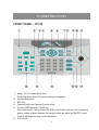
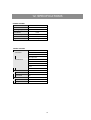
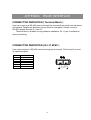
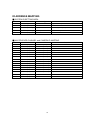
BASIC CONTROL KEYBOARD
STANDARD MODEL
Version 3.4
Before attempting to connect or operate this product, please read these instructions completely.
00-37312-0ED2
ENGLISH
User’s Manual
CONTENTS
1.PREFACE .................................................................................................................. 3
2.FEATURES ................................................................................................................ 4
3. PRECAUTIONS ........................................................................................................ 5
4.QUICK STARTING..................................................................................................... 6
QUICK START - DOME CAMERA CONTROL ......................................................... 6
QUICK START – MULTIPLEXER CONTROL .......................................................... 6
QUICK START – SYSTEM SETTING ....................................................................... 6
5.CONSTRUCTION ...................................................................................................... 7
FRONT PANEL – D7312........................................................................................... 7
REAR PANEL ........................................................................................................... 9
6.INSTALLATION........................................................................................................ 10
RS-485 CABLE....................................................................................................... 10
SYSTEM CONNECTION ........................................................................................ 10
7.OPERATION - COMMON .........................................................................................11
POWER ON .............................................................................................................11
8.OPERATION - SYSTEM SETTING.......................................................................... 12
8.1 Set Group Number .......................................................................................... 12
8.2 System Linking................................................................................................ 12
8.3 Keyboard ID Assignment................................................................................ 12
8.4 Key Press Beep ............................................................................................... 13
8.5 Alarm Reaction ................................................................................................ 13
8.6 Password Setting ............................................................................................ 13
8.7 Camera Type & Class ...................................................................................... 14
9.OPERATION - DOME CAMERA.............................................................................. 15
9.1 OSD CAMERA SETTING ................................................................................. 16
9.2 JOYSTICK ........................................................................................................ 16
9.3 PRESET FUNCTION OPERATION .................................................................. 16
9.4 SEQUENCE FUNCTION OPERATION............................................................. 16
9.5 AUTO-PAN........................................................................................................ 17
9.6 CRUISE............................................................................................................. 18
9.7 LENS CONTROL .............................................................................................. 20
9.8 CAMERA SETTING .......................................................................................... 20
9.8.1 Auto Turn-Around........................................................................................ 20
9.8.2 Zoom Speed Setting ................................................................................... 21
1
9.8.3 Digital Zoom Ratio ...................................................................................... 21
9.8.4 Alarm Setup ................................................................................................ 21
9.8.5 Speed by Zoom........................................................................................... 22
9.8.6 Set Home Position ...................................................................................... 22
9.8.7 Remote RESET .......................................................................................... 23
9.8.8 PAN Speed Test .......................................................................................... 23
9.8.9 Camera Version Check ............................................................................... 23
9.8.10 Auto Save Function................................................................................... 23
9.8.11 Line Lock Phase Adjust Function. ............................................................. 23
9.8.12 Receiver Auxiliary Switch Function. .......................................................... 24
10.OPERATION - MULTIPLEXER .............................................................................. 25
MULTIPLEXER CONTROL..................................................................................... 25
12. SPECIFICATIONS ................................................................................................ 26
APPENDIX RS485 INTERFACE .............................................................................. 27
APPENDIX
FUNCTION TREE ............................................................................... 29
APPENDIX
FIRMWARE UPGRADE ........................................................................ 31
APPENDIX
TROUBLESHOOTING .......................................................................... 32
2
1.PREFACE
This control keyboard is integrated with our full range CCTV products. User can control
our Triplex Multiplexer, High Speed Dome Camera and other CCTV devices easily.
Multi-protocols function allows user to integrate our products into existed systems of
the other brands. Built in firmware upgrade circuits allows user to upgrade the firmware
through RS-232 port easily.
3
2.FEATURES
FEATURES
1.
2.
3.
4.
5.
6.
7.
8.
CCTV devices control.
Joystick control of PTZ functions.
Preset position and pattern control.
Friendly user interface through LCD display.
Firmware upgrade is available from RS-232 port.
Rubber keypad is easier to input commands.
Remote control via RS-485 interface.
Dome cameras, Multiplexers, P/T/Z receivers and All in one cameras can be
controlled through this keyboard.
9. Maximum 16 dome cameras and one multiplexer can be controlled.
10. Optional 3-axis joystick
11. Built in P&D protocols of PELCO (Pelco Corporation).
12. Built in DSCP protocol
* PELCO is a registered trademark of PELCO corporation.
* P protocol and D protocol are protocols what PELCO corporation used.
* DM is a registered trademark of Dedicated Micro corporation.
4
3. PRECAUTIONS
1.
Do not expose the product to rain or moisture
To prevent fire or electric shock, do not expose the product to rain or moisture.
2.
Do not disassemble this product
To prevent the risk of electric shock, do not open it by yourself, please.
3.
Clean the equipment carefully.
Dry cloth is recommended for cleaning.
!
The exclamation point, within an equilateral triangle, is intended to alert the user to
the presence of important operating and maintenance (servicing) instructions in the
literature accompanying the products
The lightning flash with the arrowhead symbol, within an equilateral triangle, is
intended to alert the user to the presence of un-insulated ’’dangerous voltage’’
within the product’s enclosure that maybe of sufficient magnitude to constitute a
risk of electric shock to persons.
NOTE
This equipment generates and radiates radio frequency energy. It may cause harmful
interference to radio communication if it is not installed and used in accordance with the instruction
manual. This equipment has been tested and found to comply with the limits for a Class A computing
device pursuant to subpart J of part 15 of FCC rules which are designed to provide reasonable
protection against harmful interference when operated in a commercial environment. This equipment
has also been tested and found to comply with the requirements for a CE Class A device safety
standards.
5
4.QUICK STARTING
This section is a reference for users to quick start to manipulate dome cameras or
multiplexers in a short time.
QUICK START - DOME CAMERA CONTROL
5. D7313
Press <Camera Selection Key> and input the number of dome camera what you
want to control it. Please remember to press <ENTER> key to confirm your input.
User will be able to P/T/Z the dome camera through joystick now.
6. D7312
The keyboard will scan RS-485 bus to ensure how many devices are connected to
the bus when power on. Press number key to select a dome camera what you want
to control it directly. Please remember to press <ENTER> key to confirm your input.
QUICK START – MULTIPLEXER CONTROL
7. D7313
Press <Multiplexer Selection Key> and input the ID of multiplexer what you want to
control it. Please remember to press <ENTER> key to confirm your input. User will
be able to control the function of multiplexer through keyboard now.
8. D7312
D7312 can only control one Multiplexer. The default Multiplexer ID is 224. User can
control Multiplexer directly through the keypad of Multiplexer region.
QUICK START – SYSTEM SETTING
5. D7313
Press <CCTV System Setup Key> to modify the system setting. Please input a
correct password to enter this mode.
6. D7312
Press <CCTV System Setup Key> to modify the system setting. Please input a
correct password to enter this mode.
6
5.CONSTRUCTION
FRONT PANEL – D7312
1.
2.
3.
4.
5.
6.
Mode : CCTV System Setup Key
Press this button to modify system setting of keyboard.
Camera Setup Key
ESC Key
Direction Keys and Camera Function Keys
Camera OSD Menu key / Enter key
Press this key for 3 seconds and the OSD menu will be opened if the keyboard is
getting control of dome camera. Its function will be the same as ‘ENTER’ if user
press it and does not keep 3 seconds above.
LCD Panel
7
7.
8.
9.
10.
11.
12.
13.
14.
15.
16.
17.
Interactive message will be displayed on this LCD panel
Auto-Pan Function Key
Cruise Function Key
Keyboard Lock Up Key
Press this button for 3 seconds to lock/unlock the keyboard
Auto-Focus Key
Joystick
Multiplexer or Matrix Control Keys
Number Keys
ENTER Key
Zoom Wide/Tele Keys
Focus Near/Far Keys
Brightness Up/Down Keys
8
REAR PANEL
+
-
1. RS-232 D-SUB
User is allowed to upgrade the firmware of keyboard through this port.
2. Termination Switch (TERM ON/OFF) - Default is OFF
This switch is used to terminate the connected RS-485 communication line. It
should be kept in the OFF position normally.
3. Mode Switch ( SLAVE/MASTER ) - Default is MASTER
User can set this keyboard as a master station or slave station. User should set a
second keyboard as SLAVE station if he added this additional keyboard into
existed RS-485 bus.
4. Line Selection Switch ( LINE 4/2 ) – Default is 2 LINES
This switch is used to select full-duplex (4-lines) or half-duplex (2-lines) for the
communication lines.
5. RJ-11 Jack
This jack is a quick connection jack for demo purpose. It only support half-duplex
communication.
6. Terminal Blocks
User should connect RS-485 communication lines through this connector. We offer
additional power input positions on this connector.
7. Power Jack
Please supply power to keyboard through this power jack.
9
6.INSTALLATION
RS-485 CABLE
The communication interface between dome camera and keyboard is RS-485.
Maximum cable length for RS-485 communication over 24-gauge wire is 4000 feet
(1200 meters) without repeater. Shielded twisted pairs are recommended.
‘CAT 5’ cable is a recommended type of cable for installation. Terminal block is
also a recommended connector for long distance connection. ‘RJ-11’ jack is suitable
for testing and demo.
Please reference “Appendix RS485” for detailed pin definition.
SYSTEM CONNECTION
10
7.OPERATION - COMMON
POWER ON
Please follow the following steps to power up all devices.
STEP1: Connect all devices.
STEP2: Power up all devices except for the keyboard.
STEP3: Power up keyboard.
The LCD of keyboard will display the following message first.
CCTV Controller
Version x.xx
Fig.7.1.1
Keyboard will go into ‘Stand By Mode’ and display following message later after
system linking is finished.
CCTV Keyboard
Select Camera No.:
Fig.7.1.2
Note :
D7313 keyboard doesn’t require users follow above steps to start to control
devices. But D7312 keyboard require users follow above steps to start to control
devices. The major difference is D7312 will scan RS-485 bus to find how many
devices are connected to this RS-485 bus. User is required to re-scan devices if
they do not follow the above steps to power up D7312 keyboard.
Re-scan procedure is described on “OPREATION SYSTEM SETTING”
section. Please use “system linking” function to re-scan the devices on RS-485
bus.
■ STANDBY MODE DEFINITION
User will be able to do following actions under ‘Standby Mode'.
1. User is allowed to enter “CCTV System Setting Mode” by pressing <SYS> key.
11
8.OPERATION - SYSTEM SETTING
Keyboard will enter ‘CCTV System Setting Mode’ when user press the <SYS>
key and enter a correct password (default password is 0000). Detailed operation will
be described in the following sections. Please use "▲" and "▼" keys to scroll these
setup items.
1.0 System Setting
Enter password [____]
Fig.8.0.1
8.1 Set Group Number
Item 1.1 allows user to select a group number what they want to control. Please
press "◄" or "►" button to select a group number.
1.1 Set Group Number
(1-16)
Fig.8.1.1
8.2 System Linking
Item 1.1 allows user to scan connected cameras on the RS485 bus again. Please
press "◄" or "►" button to start a new scanning session.
1.1 System Linking
Press ◄ ► to search
Fig.8.2.1
8.3 Keyboard ID Assignment
Item 1.2 allows you to assign a new ID for this keyboard. Please press "◄" or "►"
button to change the ID number. Default ID number for keyboard is 000. Please assign
a different ID for different keyboard if more than one keyboard is connected to one
RS-485 bus.
1.3 Set Keyboard ID
(240-254):240
Fig.8.3.1
12
8.4 Key Press Beep
Item 1.4(as Fig.8.4.1) allows user to turn on/off the built in buzzer. Buzzer will alert
user after key is pressed when this setting is ON. Press ◄ or ► key to change the
setting.
1.4 Key Press Beep
[OFF]
ON
Fig.8.4.1
8.5 Alarm Reaction
Item 1.11(as Fig.8.11.1) allows user to turn on/off the response action of keyboard
when an alarm message is sent to keyboard from other devices
Basically, keyboard will receive an alarm message after the alarm port on dome
camera is triggered. Keyboard can be programmed to do following actions after
keyboard received an alarm message.
1. Buzzer beep.
2. Link to the dome camera which broadcast this alarm message.
3. Switch the video channel to full screen from multiplexer.
Default setting is OFF. Press ‘◄’ or ‘►’ key to change the setting.
1.5 Alarm Reaction
[OFF]
ON
Fig.8.5.1
8.6 Password Setting
Item 1.6.1 (as Fig.8.6.1) allows user to change the password of keyboard. User
must input a new password twice correctly to confirm password change.
1.6.1 Password[****]
1.6.2 Password[****]
Confirm [____ ]
Fig.8.6.1
Fig.8.6.2
13
8.7 Camera Type & Class
Item 1.7 (as Fig.8.7.1) allows users to assign proper individual protocol for every
camera. Press <ENTER> to start to assign individual protocol to every camera. Press
◄ or ► key to change the setting, ▲ or ▼ key to choose different camera.
1.7.1 Group #01 – 01
[DSCP] Pelco-D Pelco-P
1.7 Camera Type
Press ENTER to setup
Fig.8.7.2
Fig.8.7.1
14
9.OPERATION - DOME CAMERA
Please press the ID of dome camera to start to control dome camera under “Standby
Mode”.
CCTV Keyboard
Select Camera No.:
Fig.9.0.1
Keyboard will enter ‘Camera Control Mode’ after user selects a camera to control
it. User can full control the function of cameras now.
CAMERA CONTROL MODE
xxx P/T/Z/F/OSD Cam
___
Fig.9.0.2
The first row on LCD contains following information.
( P=Pan, T=Tilt, Z=Zoom, F=Focus, OSD=OSD available).
The second row on LCD allows user to input any number. User can input a dome
ID and press ‘ENTER’ to select another dome camera to control it. Or user can input a
preset point or other parameters of camera. Detail operation instruction will be
described in the following sections.
15
9.1 OSD CAMERA SETTING
Press <CAMERA MENU> button for 3 seconds to open the OSD menu of dome
camera if the selected camera equipped the OSD function. User can move OSD bar
through direction keys on keyboard after the OSD menu is opened.
9.2 JOYSTICK
Push joystick right/left/up/down to move dome camera directly.
9.3 PRESET FUNCTION OPERATION
User is allowed to control the built in preset function of dome camera under “Camera
Control Mode”. Please follow the following instructions to manipulate this function.
CAMERA CONTROL MODE
xxx P/T/Z/F/OSD Cam
___
Fig.9.3.1
■ Setting
Press a number key for preset point such as <2>. Press <SET PRESET> to record
this position as preset point 2.
■ Recall preset position
Press a number key for preset point such as <2>. Press <GO PRESET> to go to
the preset position 2.
9.4 SEQUENCE FUNCTION OPERATION
User is allowed to control the built in sequence function of dome camera under
‘Camera Control Mode’. There are 4 sets of sequence line can be programmed into
dome cameras. Please follow the following instructions to manipulate this function.
■ Setting
1. Press a number key to set a sequence line such as <1>. Press <SET SEQ.>
to start to modify parameters of sequence 1.
xxx. PST SPD
[001] [10]
DWELL
[000]
Fig.9.4.1
※PST is a shortcut of ‘Preset Point’. ( 1 ~128 )
※SPD is a shortcut of ‘Speed’, ( 1~15 )
16
※DWELL is a shortcut of ‘Dwell time’. Its unit is seconds. ( 1~127 )
2. LCD is displaying “001. PST SPD DWELL” now. You can edit the parameters
such as <4> <ENTER> for PST, <1> <5> <ENTER> for SPD and <5>
<ENTER> for DWELL. That means that the first preset point for sequence 1
is preset point 4, dome camera will staying 5 seconds there and dome will go
to next preset with speed 15.
3. LCD is displaying “002.PST SPD DWELL” now. Please edit the parameters.
4. LCD is displaying “003.PST SPD DWELL” now. Please press <SETUP> to
end the session if you need two presets only.
5. User is allowed to use ▲ ▼ keys to scroll up or down the all pages. User can
also use ◄ ► keys to move the cursor to a item what they want to edit it.
■ Execute sequence function
1. Press a number key to specify a sequence number what you want to
execution.
2. Press <RUN SEQ.> to start sequence function.
xxx P/T/Z/F/OSD Cam
Running Sequence 1~4
Fig.9.4.2
User can insert or delete a preset position from sequence line easily. Press <INS> key
to insert a preset position into the sequence line. Press <DEL> key to delete the
current preset position from this sequence line.
User can press <ESC> or <ENDSEQ> key to exit sequence mode after sequence
line editing is finished. The difference between these two keys is: <ENDSEQ> will
remove all preset positions behind current preset position; <ESC> will keep all preset
positions.
9.5 AUTO-PAN
User is allowed to control the built in Auto-Pan function of dome camera under
‘Camera Control Mode’. Please follow the following instructions to manipulate use this
function.
■ Setting
1. Press <AutoPan> to enter Auto-Pan mode. The LCD on keyboard will display
“1.RUN 2.SETTING”.
3.0 AutoPan select:
1. Run
2.17Setting
Fig.9.5.1
2. Press <2> to start to edit parameters of Auto-Pan.
3. Move dome camera to a specific position and press <ENTER> to save it as
the start position of scan region.
3.1 Auto Pan Setting
Enter for Start Pos.
Fig.9.5.2
4. Pan dome camera to another position and press <ENTER> to save it as the
end position of scan region.
3.2 Auto Pan Setting
Enter for End Pos.
Fig.9.5.3
5. Using direction key to select the scan direction what you want. Press
<ENTER> to confirm this selection.
6. Using direction keys to select speed of Auto-Pan function. Press <ENTER>
to confirm this selection.
■ Execute Auto-Pan function
1. Press <Auto Pan> to enter Auto-Pan mode. The LCD on keyboard will
display “1.RUN 2.SETTING”.
2. Press <1> to execute Auto-Pan function.
xxx P/T/Z/F/OSD Cam
Running Auto Pan…
Fig.9.5.4
9.6 CRUISE
User is allowed to control the built in Cruise function of dome camera under ‘Camera
Control Mode’. Please follow the following instructions to manipulate this function.
■ Setting
1.
Press <CRUISE> key on keyboard to select a mode of cruise function.
18
4.0 Cruise select:
1. Run
2. Setting
Fig.9.6.1
2.
3.
LCD is displaying “1. RUN
2.SETTING” now. Press <2> to enter
modification mode.
LCD is displaying “ENTER for START POS” now. Press <ENTER> to start to
input cruise path.
4.1 Cruise setting
Enter for Start Pos.
Fig.9.6.2
4.
LCD is displaying “ENTER for END POS” now. User can move dome camera
to patrol a path and this path will be recorded into dome camera as cruise
path.
Press <ENTER> to stop cruise recording procedure.
4.2 Cruise setting
Enter for End Pos.
Fig.9.6.3
5.
LCD is displaying “ENTER for SAVING” now. Press <ENTER> to command
dome camera to save this cruise path into EEPROM.
4.3 Cruise setting
Enter for Saving..
Fig.9.6.4
■ Execute cruise function
1.
Press <CRUISE> key on keyboard to select a mode of Cruise function.
Group[xx]Device[xxx]
Running Cruise…
Fig.9.6.5
2.
LCD is displaying “1. RUN
function.
2.SETTING” now. Press <1> to start cruise
19
9.7 LENS CONTROL
User can control the functions of lens through “Lens Control Keys” under “Camera
Control mode”.
■ Zoom Function
1. Tele : Press <Tele> key to zoom in the lens.
2. Wide : Press <Wide> key to zoom out the lens.
■ Focus Function
Press focus keys to adjust the focus of lens under manual focus mode.
1. Focus Near
: Press <Focus Near> key to move focus lens near.
2. Focus Far
: Press <Focus Far> key to move focus lens far.
■ Brightness Function
Press brightness keys to adjust the brightness of lens.
1. Brightness +
2. Brightness-
: Press <Brightness +> key to increase the brightness of video.
: Press <Brightness -> key to decrease the brightness of video.
■ AutoFocus Function
Press <AutoFocus> key to toggle AutoFocus function.
9.8 CAMERA SETTING
Press <SETUP> key to enter camera setting mode under “Camera Control Mode”.
User can setup the main features of cameras here. Password is required at first stage.
CAMERA SETTING MODE
2.0 Camera Setting
Enter password [____]
Fig.9.8.1.
Please press ▲ ▼ keys to scroll page up/down and press ◄ ► keys to change the
setting of items. Press <ESC> key to exit this menu.
9.8.1 Auto Turn-Around
Auto Turn-Around function allows user to keep tracking object even the object
pass through the bottom of camera. You needn’t rotate 180 degrees in pan
direction to keep observing the object. This function will do this for you quickly
2.1 Auto Turn-Around
[OFF]
ON
Fig..9.8.1.1
20
9.8.2 Zoom Speed Setting
User can select a zoom speed to manipulate the lens of camera.
2.2 Zoom Speed
[SLOW]
FAST
Fig.9.8.2.1
9.8.3 Digital Zoom Ratio
User can select a proper digital zoom ratio to control the cameras. The higher
digital zoom ratio, the lower video image quality on screen.
2.3 Digital Zoom X
2X
Fig.9.8.3.1
9.8.4 Alarm Setup
The dome cameras built in 4 alarm input connectors. User can configure the alarm
configuration here.
2.4 Alarm Setup
Press Enter to Setup
Fig.9.8.4.1
Item 2.4.1 allows user to set a dwell time for all alarm pins. This dwell time means
that dome camera will go to a specific preset position and wait for a ‘dwell time’
then go back to original status.
2.4.1 Dwell Time:
[010] sec
Fig.9.8.4.2
Item 2.4.2 allows user to set the configuration of alarm pin1. Press ‘ENTER’ to
enter this menu.
2.4.2 Alarm1 Setting
Press Enter to Setup
Fig.9.8.4.3
Item 2.4.2.1 allows user to enable or disable alarm action related to alarm pin1.
21
2.4.2.1 Alarm1 Setup
[OFF]
ON
Fig.9.8.4.4
Item 2.4.2.2 allows user to configure the normal status of alarm pin1. ‘N.O.’ means
normal status is open circuit. That means alarm sensor will short this alarm pin
when alarm sensor is triggered.
2.4.2.2 Alarm1 Setup
[NO]
NC
Fig. 9.8.4.5
Item 2.4.2.3 allows user to configure the mapped preset position for alarm pin1.
That means dome camera will go to that preset position when a alarm sensor is
triggered on alarm pin1.
2.4.2.3 Alarm1 Setup
Preset : [001]
Fig. 9.8.4.6
9.8.5 Speed by Zoom
User can enable “Pan/Tilt speed inverse proportional to zoom ratio” function. User
can track an object easily through this function.
2.5 Speed by Zoom
[OFF]
ON
Fig. 9.8.5.1
9.8.6 Set Home Position
This item is used to set a home position for dome camera.
2.6 Home Position
Press ENTER to setup
Fig.9.8.6.1
22
9.8.7 Remote RESET
This item is used to reset a dome camera remotely.
2.7 Remote Reset
Press <> to proceed
Fig. 9.8.7.1
9.8.8 PAN Speed Test
This item is used to demo the speed of dome camera for customers.
2.8 PAN Speed Test
Input PAN Speed:
Fig. 9.8.8.1
9.8.9 Camera Version Check
This item allows user to find the version of camera. User can inform this data to
factory to troubleshoot encountered problems.
2.9 Camera Version
H/W:VxxS/W:Vxx
Fig. 9.8.9.1
9.8.10 Auto Save Function.
Auto Save function will record current position when user defined period of time is
reached. Dome will go to that position after the power of your installation site is
recovery after shutdown. ( 1~42 min )
2.10 Auto Save Func.
01 Min.
Fig. 9.8.10.1
9.8.11 Line Lock Phase Adjust Function.
This function enable user to adjust the line lock signal remotely. You can adjust
the phase of line lock signal to synchronize the system from keyboard.
2.11 Llock Phase Adj.
Press ◄ ► to - / +
Fig. 9.8.11.1
23
9.8.12 Receiver Auxiliary Switch Function.
Users can press 1 or 2 to select one of two receiver auxiliary switches and then
press ◄ ► key to turn on/off receiver auxiliary switch.
2.12 Receiver AUX
Press 1/2 to setup
Fig. 9.8.12.1
2.12 Receiver AUX1
ON
[OFF]
Fig. 9.8.12.2
24
10.OPERATION - MULTIPLEXER
MULTIPLEXER CONTROL
D7312 can only control one Multiplexer. The default Multiplexer ID is 224. User can
control Multiplexer directly through the keypad of multiplexer region.
25
12. SPECIFICATIONS
GENERAL FEATURES
Environment
Indoor
Controller I/F
RS-485
Operating Temperature
0° – 40 °C
Power Source
12VDC
Power Consumption
Dimensions
5W
H65mm X W300mm X D175mm
Weight
1.5kg
CONTROL FEATURES
Dome Camera
Lens Control
YES
Zoom: Tele/Wide
Focus: Near/Far/Auto
IRIS: Open/Close
Pan/Tilt Control
Manual
Preset
Sequence
Cruise
Auto-Pan
Multiplexer
YES
Mode Selection
Yes
Menu Control
Yes
Supported Protocols
D&P protocol
YES
DSCP protocol
YES
26
APPENDIX
RS485 INTERFACE
CONNECTOR DEFINITION ( Terminal Block )
User can construct a RS-485 network through the terminal block located on rear panel
of keyboard. Detailed pin definition can be found on rear panel. Please construct
RS-485 network through ‘D+’ and ‘D-‘.
Terminal block is suitable for long distance installation. RJ-11 jack is suitable for
demo and testing.
CONNECTOR DEFINITION ( RJ-11 6P6C )
User could construct a RS-485 network through pin4 and pin5. Pin2 and pin3 is used
for special purpose.
Pin No.
1
2
3
4
5
6
Definition
+12V in
GND
DA
DB
-
.
27
ID ADDRESS MAPPING
■ SYSTEM ID SETTING AREA
Item
1
2
3
4
5
ID Address
00H
(0)
01H~ DFH (1~223)
E0H~ EFH (224~239)
F0H~ FEH (240~254)
FFH
(255)
Device Type
Host controller
Dome cameras
Multiplexer
Control keyboard
Matrix
Remark
Keyboard or computer
Total 223 Dome cameras
224~239 ( Mpx1~Mpx16)
CCTV control keyboard
■ MULTIPLEXER CHANNEL and CAMERA ID MAPPING
MUX No
1
2
3
4
5
6
7
8
9
10
11
12
13
14
15
16
E0H
E1H
E2H
E3H
E4H
E5H
E6H
E7H
E8H
E9H
EAH
EBH
ECH
EDH
EEH
EFH
MUX ID
(224)
(225)
(226)
(227)
(228)
(229)
(230)
(231)
(232)
(233)
(234)
(235)
(236)
(237)
(238)
(239)
Camera ID
01H~ 10H
(1~16)
11H~ 20H
(17~32)
21H~ 30H
(33~48)
31H~ 40H
(49~64)
41H~ 50H
(65~80)
51H~ 60H
(81~96)
61H~ 70H
(97~112)
71H~ 80H
(113~128)
81H~ 90H
(129~144)
91H~ A0H
(145~160)
A1H~ B0H (161~176)
B1H~ C0H (177~192)
C1H~ D0H (193~208)
D0H~ DFH (209~223)
None
None
28
Remark
Map to channel 1~16 of MPX
Only 15 Dome can be connect
Can connect to normal camera
Can connect to normal camera
APPENDIX
FUNCTION TREE
■ DOME FUNCTION TREE
Function
Operation
Description
Dome Selection
<1> ~ <16>
Press number key to select a dome camera to control it.
Lens Control
<Zoom Wide>
Zoom Out
<Zoom Tele>
Zoom In
<Focus Near>
Focus Near
<Focus Far>
Focus Far.
<Auto / Focus>
Auto-Focus
<Brightness ->
Brightness Down
<Brightness +>
Brightness Up
Call Preset
<1> ~ <128> + <Go Preset>
Recall preset point
Save Preset
<1> ~ <128> + <Set Preset>
Record preset point
<1> ~ <4> + <Run SEQ>
Execute Sequence
<1> ~ <4> + <Set SEQ>
Edit Sequence
<AUTOPAN> + <1>
Execute Autopan
<AUTOPAN> + <2>
Edit Autopan
<Camera Menu>
Press this button for 3 seconds to open OSD on
OSD Open
camera.
Lock
<LOCK/UNLOCK>
Lock/Unlock keyboard
Setup
<SETUP>
Enter setup menu of camera
1. Auto Turn-Around
Use ◄ ► key to turn on/off
2. Zoom Speed
Use ◄ ► key to turn fast/slow
3. Digital Zoom
Use ◄ ► key to turn x1/x2/x4/x8
4. Alarm Set
On/Off, NC/NO and Preset setting of alarm function
5. Speed by Zoom
PAN/TILT speed proportional to zoom ratio
6. Home Position
7. Remote Reset
8. Pan speed test
9. Camera Version
Camera's version display
10. Auto Save Func.
Auto restoring parameters setting
11. LLock Phase Adj
12. Receiver Aux
29
■ MULTIPLEXER FUNCTION TREE
Function
Operation
Description
Multiplexer Function
Key pad on Multiplexer region
Multiplexer control
■ SYSTEM FUNCTION TREE
Function
Operation
Description
System Setting
<SYS>
CCTV System Setting Mode
1. Set Group Number
Select group to control devices
2. System Linking
Scan the existed devices
3. Set Keyboard ID
Keyboard ID Setting
4. Key Press Beep
Use ◄ ► key to Turn ON/OFF
5. Alarm Reaction
Use ◄ ► key to Turn ON/OFF
6. Password
Set New Password
7. Camera Type
30
APPENDIX
FIRMWARE UPGRADE
Please follow the following procedures to upgrade the firmware of keyboard.
STEP1: Connect PC to the control keyboard through standard RS-232 cable.
STEP2: Execute the Auto-unpack.exe on the PC.
This program will create a directory which is called as “Keyboard” then it will
unpack three files into that directory. They are ‘Keyboard.exe’, ‘Keyboard.tsk’
and ‘Readme.doc’. Please read the Readme.doc carefully before upgrading
your keyboard.
STEP3 Make sure the setting of ‘S2’ switch is set to slave mode on the rear board.
Please reference ‘Section 2.3’ to make sure S2 (RS-232 setting) is set to ‘S’
(slave) position.
STEP4 Press ‘SETUP’ key and do not release it then power up the keyboard.
The LCD will display “Ready to Download” message on keyboard.
STEP5 Execute Keyboard.exe on the PC.
The download process will be started if you select a correct COM port for this
windows application. It will spend one or two minutes to finish the progress.
Please power off the keyboard after the download process is finished.
Keyboard will operate through new firmware after user power up again.
31
APPENDIX
TROUBLESHOOTING
Please reference “D731X Troubleshooting Guide - Class1”.
The detailed information and instructions are listed in that document.
32