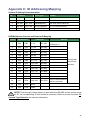
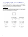
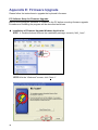
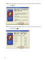
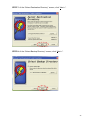
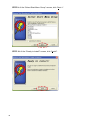
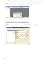
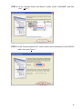
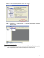
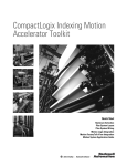
1
CCTV System Control Keyboard User’s Manual Version 2.3 00P373130ZSEB3 Preface The information given in this manual was current when published. The company reserves the right to revise and improve its products. All specifications are subject to change without notice. Notice To work with the Speed Dome Cameras and Control Keyboard, any installer or technician must have the following minimum qualifications: • A basic knowledge of CCTV systems and components • A basic knowledge of electrical wiring and low-voltage electrical hookups • Have read this manual completely Copyright Under copyright laws, the contents of this user manual may not be copied, photocopied, translated, reproduced or reduced to any electronic medium or machine-readable format, in whole or in part, without prior written permission of the company. Important Information Before proceeding, please read and observe all instructions and warnings in this manual. Retain this manual with the original bill of sale for future reference and, if necessary, warranty service. When unpacking your unit, check for missing or damaged items. If any item is missing, or if damage is evident, DO NOT INSTALL OR OPERATE THIS PRODUCT. Contact your dealer for assistance. Regulation This symbol on the product or on its packaging indicates that this product shall not be treated as household waste in accordance with Directive 2002/96/EC. Instead it shall be handed over to the applicable collection point for the recycling of electrical and electronic equipment. By proper waste handling of this product you ensure that it has no negative consequences for the environment and human health, which could otherwise be caused if this product is thrown into the garbage bin. The recycling of materials will help to conserve natural resources. For more details information about recycling of this product, please contact your local city office, your household waste disposal service or the shop where you purchased the product. 1 Compliance is evidenced by written declaration from our suppliers, assuring that any potential trace contamination levels of restricted substances are below the maximum level set by EU Directive 2002/95/EC, or are exempted due to their application. 2 Cautions • Do not expose the product to rain or moisture To prevent fire or electric shock, do not expose the product to rain or moisture. • Do not disassemble this product To prevent the risk of electric shock, do not disassemble the product. There are no user serviceable parts inside. • Clean the equipment carefully. Dry cloth is recommended for cleaning. ! The exclamation point, within an equilateral triangle, is intended to alert the user to the presence of important operating and maintenance (servicing) instructions in the literature accompanying the products The lightning flash with the arrowhead symbol, within an equilateral triangle, is intended to alert the user to the presence of un-insulated ’’dangerous voltage’’ within the product’s enclosure that maybe of sufficient magnitude to constitute a risk of electric shock to persons. NOTE This equipment generates and radiates radio frequency energy. It may cause harmful interference to radio communication if it is not installed and used in accordance with the instruction manual. This equipment has been tested and found to comply with the limits for a Class A computing device pursuant to subpart J of part 15 of FCC rules which are designed to provide reasonable protection against harmful interference when operated in a commercial environment. This equipment has also been tested and found to comply with the requirements for a CE Class A device safety standards. 3 Table of Contents 1. 2. 3. Overview .....................................................................................................................6 Product Features ........................................................................................................7 Functional Buttons and Connectors.........................................................................8 3.1 Front Panel .......................................................................................................8 3.2 Rear Panel ........................................................................................................9 4. System Connection and Power Up .........................................................................10 4.1 Connecting RS-485 Cables.............................................................................10 4.2 RJ-11 (6P6C) Connector Definition.................................................................10 4.3 Power on the Devices .....................................................................................10 4.4 Standby Mode Actions ....................................................................................11 5. Keyboard System Setting ........................................................................................12 5.1 System Linking................................................................................................12 5.2 Keyboard ID Assignment ................................................................................12 5.3 System Monitor ...............................................................................................12 5.4 RS-232 Baud Rate Setting..............................................................................13 5.5 System Date Setting .......................................................................................13 5.6 System Time Setting .......................................................................................14 5.7 Date Time Correction ......................................................................................14 5.8 System Alarm List ...........................................................................................14 5.9 Camera Type and System Baud Rate Setting ................................................14 5.10 Key Press Beep ..............................................................................................16 5.11 Alarm Reaction ...............................................................................................16 5.12 5.13 6. Dome Camera Control..............................................................................................18 6.1 Entrance into Camera OSD Menu ..................................................................18 6.2 Joystick ...........................................................................................................19 6.3 Preset Function ...............................................................................................19 6.3.1 Setting through Keyboard ..................................................................19 6.3.2 Setting through Camera OSD Menu ..................................................20 6.4 Sequence Function .........................................................................................20 6.5 6.6 6.7 4 Password Setting ............................................................................................16 Key Lock .........................................................................................................17 6.4.1 Setting through Keyboard ..................................................................20 6.4.2 Setting through Camera OSD Menu ..................................................23 Auto-Pan .........................................................................................................24 6.5.1 Setting through Keyboard ..................................................................24 6.5.2 Setting through Camera OSD Menu ..................................................25 Cruise..............................................................................................................25 6.6.1 Setting through Keyboard ..................................................................25 6.6.2 Setting through Camera OSD Menu ..................................................26 Camera Lens Control ......................................................................................26 7. DVR Control ..............................................................................................................28 7.1 Mode Function ................................................................................................28 7.2 Freeze Function ..............................................................................................28 7.3 SEQ Function..................................................................................................29 7.4 List Function....................................................................................................29 7.5 Playback Function...........................................................................................29 7.6 Fast Forward and Rewind ...............................................................................29 7.7 Call Function ...................................................................................................30 7.8 MENU .............................................................................................................30 7.9 SET .................................................................................................................30 7.10 Direction Keys .................................................................................................31 7.11 ESC.................................................................................................................31 7.12 ENTER/ZOOM ................................................................................................31 Appendix A: Specification ..............................................................................................32 Appendix B: Function Tree .............................................................................................33 Appendix C: ID Addressing Mapping.............................................................................35 Appendix D: Super MPX and Super MMX System ........................................................36 Appendix E: Firmware Upgrade .....................................................................................38 5 1. Overview This CCTV System Control Keyboard can be integrated with a full range of CCTV products easily, such as Digital Video Recorders (DVR), cameras and other CCTV devices with RS-485 interface for remote control and system configuration. Back lit LCD display and 3-axis joystick control provide userfriendly operations. Built-in firmware upgrade circuits allow users to upgrade firmware through the RS-232 port. The system configuration diagram below shows the application of the control keyboard in a comprehensive surveillance system. NOTE: To extend the network distance up to 1.2 km (4000 feet) and to protect the connected devices, it is highly recommended to place a repeater in the mid-point. However, a repeater may be needed in the network distance less than 1.2 km if the used cables are not the CAT 5, 24-gauge cables. 6 2. Product Features • • • • • • • • CCTV devices control 3-axis Joystick control of PTZ functions (Optional) Preset, sequence, cruise and other automatic control modes User-friendly interface through LCD display Easy firmware upgrade via RS-232 port Rubber keypad makes input easily Remote control via RS-485 interface. Control of dome cameras, DVRs/Multiplexers, P/T/Z receivers and all-in-one cameras • Maximum 255 devices can be connected. (223 Cameras or Receivers, 16 Control Keyboards and 17 DVRs/Multiplexers) • • Built-in clock for date and time recording (3-Axis Keyboard) Built-in protocols: DSCP, Pelco D and Pelco P 7 3. Functional Buttons and Connectors 3.1 Front Panel 1 3 5 7 9 11 13 15 17 19 21 8 Multiplexer/DVR Selection Key Camera/Dome Selection Key Camera Setup Key Direction Keys and Function Keys LCD Panel Cruise Function Key Auto-Focus Function Key Multiplexer, DVR or Matrix Control Keys Home Function Key F1~ F4: Reserved Focus Near/Far Keys 2 4 6 8 10 12 14 16 18 20 22 Reserved CCTV System Setup Key ESC Key Camera OSD Key and Enter Key Auto-Pan Function Key Keyboard Lock Up Key Joystick Number Keys Enter Key Zoom Wide/Tele Keys Brightness Up/Down Keys 3.2 Rear Panel Connector 1 2 Description RS-232 Users are allowed to upgrade firmware of the D-SUB keyboard through this port. Termination Switch This switch is used to terminate the connected RS-485 communication line. It should be kept in the OFF position normally. The default is OFF. Users can set this keyboard as a master or slave 3 Mode station. An additional keyboard added into the Switch system should be a SLAVE station. The switch is MASTER at factory default. This switch is used to select full-duplex (4-lines) or Line 4 Selection half-duplex (2-lines) for the communication lines. The default is 2 lines. Switch NOTE: The 4-lines mode is not available currently. This jack is a quick connection jack for demo 5 RJ-11 Jack purpose. It only supports half-duplex communication. Terminal Blocks Users should connect RS-485 communication lines through this connector. There is an additional power 6 input position on this connector (DC 12V), as shown in the figure. 7 Power Jack Please power up the keyboard through this power jack. 9 4. System Connection and Power Up The control keyboard can be connected with a speed dome camera or DVR. The following sections will describe basic connections in a surveillance system. 4.1 Connecting RS-485 Cables To operate dome cameras, a control keyboard (or other control device, e.g. DVR) is needed to communicate all devices via RS-485 interface. The CAT 5 (Shielded twisted pairs) cables are recommended for RS-485 communication; maximum cable length for over 24-gauge wire is 4000 feet (1219 meters). If the total cable length is over 4000 feet, using a repeater to enlarge the signals is recommended. Terminal block is designed for long distance installation. Users can construct a RS-485 network through the terminal block located on the rear panel of the control keyboard. Detailed pin definition can be found on the terminal block. 4.2 RJ-11 (6P6C) Connector Definition RJ-11 jack is designed for demo and testing purpose, and only supports half-duplex communication. Users could construct a RS-485 network through pin 4 and pin 5. Refer to the table below for pin definition. Pin No. Definition 1 2 +12V in 3 GND 4 D+ 5 D- 6 4.3 Power on the Devices Please follow the steps to power up all devices. (1) Connect all devices. Before connecting cameras and DVR to the system control keyboard, please finish all protocol and unit ID setups. (2) Power up all devices except for the keyboard. Make sure images of connected cameras are displayed on the monitor screen. (3) Power up the control keyboard. 10 As the keyboard is powered on, the software version will be displayed on the LCD as shown below. CCTV Controller Version x.xx The (3-axis) keyboard LCD will display the date and time when the keyboard is under standby mode. CCTV Keyboard 2006/07/05 12:00:00 4.4 Standby Mode Actions Users will be able to do the following actions under the Standby Mode. • • Press the <SYS> key to enter the System Setup mode. Enter the Camera Control mode by pressing <Camera/Dome Mode> key and execute further camera controls such as P/T/Z operations and camera OSD setup. • Enter the DVR/Multiplexer Control mode by pressing <DVR /Multiplexer Mode> key and carry on further DVR control related settings. For detailed instructions on keyboard system setting, dome camera control and DVR control, please refer to the following chapters. 11 5. Keyboard System Setting The keyboard will enter System Setup mode when users press the <SYS> key and enter a correct password (default password is 0000). Detailed operation will be described in the following sections. Please use ▲ (RUNSEQ) and ▼ (SETSEQ) keys to scroll these setup items. 1.0 System Setting Enter password [____] 5.1 System Linking Item 1.1 allows users to scan connected dome cameras on the RS-485 bus; fixed cameras will not be searched out. Please press ◄ or ► button to start a new scanning session. 1.1 System Linking Press ◄► to search.. 5.2 Keyboard ID Assignment The item allows users to assign a new ID for this keyboard. Please press ◄ or ► key to change the ID number. The default ID of the control keyboard is 240. Please assign different ID for different keyboard if more than one keyboard is connected to one RS-485 bus. 1.2 Set Keyboard ID (0 or 240-254):240 NOTE: No two control keyboards connected to the same RS-485 bus should be given the same ID. 5.3 System Monitor Users could select a specific system monitor mode according to different system structure. The options selectable include a. MPX main monitor, c. Super MPX mode (Super Multiplexer) and d. Super MMX mode (Multiplexer-Matrix); b. Matrix output is reserved. Generally, if there are less than 16 cameras within a system, a. MPX main monitor would be a proper alternative. For a large-scaled system, the connected cameras may exceed 16 or more. It is suggested to select either the Super MPX mode or the Super MMX mode for such a situation. Please refer to Appendix D: Super MPX and Super MMX System for further details of Super MPX and Super MMX modes. 12 1.3 System Monitor 1.3 System Monitor a. MPX main monitor b. Matrix output 1.3 System Monitor 1.3 System Monitor c. Super MPX mode d. Super MMX mode NOTE: In the Super MMX mode, the key <ENTER/ZOOM>, as shown below, will become ineffective either under Dome Camera or DVR Control. In other modes (option a, b and c above), press <ENTER/ZOOM> will perform digital zoom in/out. For other use of the key, please refer to 7.7 MENU and 7.11 ENTER/ZOOM. 5.4 RS-232 Baud Rate Setting The item allows users to set RS-232 baud rate when needed. The options include 9600, 4800 and 2400bps. 1.4 RS232 Baudrate 1.4 RS232 Baudrate a. Baudrate 9600bps b. Baudrate 4800bps 1.4 RS232 Baudrate c. Baudrate 2400bps 5.5 System Date Setting The item allows users to set the control keyboard system date. Please press ◄ and ► button to select a column (year, month and date) to modify, and input new system date directly using the number keys located on the control keyboard. Press <ESC> to exit this mode. 1.5 Date setting Press Enter to setup 1.5.1 Date setting YY:xx Mth:xx Day:xx NOTE: Date setting function is only available for the 3-axis control keyboard. 13 5.6 System Time Setting The item allows users to set the control keyboard system time. Input the number into the blocks (hour, minute and second) with number keys. Press ◄ and ► keys to select an input block for modification. Press <ESC> to exit this mode. 1.6 Time setting Press Enter to setup 1.6.1 Time setting hh:xx mm:xx ss:xx NOTE: Time setting function is only available for the 3-axis control keyboard. 5.7 Date Time Correction Item 1.7 allows users to synchronize the local time (of the keyboard) to all devices. The keyboard will synchronize the time of all devices to the time of the keyboard. Please press <ENTER> to enable the function; press <ESC> to exit this mode. 1.7 DateTime Correct Press Enter to setup NOTE: The function is only available for the 3-axis control keyboard. 5.8 System Alarm List The item allows users to list the latest 10 Alarm information from system bus, including event triggered time and triggered camera’s ID. Press <ESC> to exit this mode. 1.8 Alarm list Press Enter to setup 1. xx/xx/xx xx:xx:xx Alarm camera ID: xxx NOTE: Date/time information won’t be shown on the 2-axis keyboard. 5.9 Camera Type and System Baud Rate Setting The item allows users to assign a proper protocol or camera type to each camera through the keyboard so that when under the dome control mode, users could call a specific camera and control it. In addition, users can set system 14 baud rate. Press <1> to assign a protocol. Press ◄ or ► key to change the setting and ▲ or ▼ key to select a camera; Press <ESC> when finished. The options include DSCP, PELCO-D, PELCO-P and Fix Camera. 1.9 Camera Type & Comm. 1.9.1 Camera ID #001 Press 1: Type 2: Comm. [DSCP] PEL-D PEL-P ► 1.9.1 Camera ID #001 ◄ FixCam Press <2> to set system baud rate. Press ◄ or ► key to change the setting. 1.9.2 System Baud Rate 1.9.2 System Baud Rate a. Default Setting b. Baudrate 9600bps 1.9.2 System Baud Rate 1.9.2 System Baud Rate c. Baudrate 4800bps d. Baudrate 2400bps System Baud Device Rate Default 9600 4800 2400 9600 9600 4800 2400 2400 9600 4800 2400 4800 9600 4800 2400 9600 9600 4800 2400 Type Dome Camera (DSCP) Dome Camera (Pelco-D) Dome Camera (Pelco-P) DVR (DSCP) Basically, the camera ID here means camera number. This number is for users to select a camera, which may be of fixed type or dome type, to display a full-screen video output on the monitor through DVRs/MUXs. If this camera is a dome camera, users can control and set this camera through RS-485 connection; each device on the bus should have a unique ID. The keyboard needs to recognize whether a camera is of fixed type or dome type to make correct control and setting. Please refer to Appendix C: ID Address Mapping for information on camera ID and DVR/MUX channel mapping. NOTE: If use a speed dome, ensure the camera No. and camera ID (RS-485) are the same. Additionally, remember to assign a camera No. 15 to each fixed camera within the system, otherwise the fixed camera(s) won’t be searched out under the dome control mode. 5.10 Key Press Beep The item allows users to turn on/off the key beep. When the setting is ON, the key beeps when being pressed. Press ◄ or ► key to change the setting. Then press ▼ to go to next item. 1.10 Key Press Beep [OFF] ON 5.11 Alarm Reaction The item allows users to enable/disable the alarm response function of the keyboard. The default setting is OFF. Press ◄ or ► key to change the setting. 1.11 Alarm Reaction [OFF] ON If alarm reaction is enabled, actions would occur as follows. (1) (2) (3) 5.12 Buzzer beep and LCD flashes when the control keyboard receives alarm signals Afterwards, if users move the joystick or press any key, the control keyboard will try to link to the camera that broadcasts the alarm message. Once the camera is linked, video from it will be displayed in full screen on the monitor. Password Setting The item allows users to change the password of a keyboard. It is required to input a new 4-digits password twice correctly to confirm password change. 1.12.1 PassWord[****] 16 1.12.2 PassWord[****] confirm[___] 5.13 Key Lock Press and hold this key, as shown below, for three seconds and then keys on the control keyboard will be locked, with the LED lightening. To unlock the keys, press and hold this key again for three seconds. 17 6. Dome Camera Control To enter Camera Control mode, press the <Camera/Dome Mode> key ; its LED will be lightening. Then input the ID of the assigned dome camera and press <ENTER> to confirm (see the column below). Camera Control Enter Camera No.: xxx After confirmation, the LCD will display as shown below. Under the situation, users could fully control the dome camera with the joystick. xxx P/T/Z/F/OSD Cam ___ The first row of the LCD display above contains following information: P=Pan, T=Tilt, Z=Zoom, F=Focus, OSD=OSD function available. The second row of the display shows an input number under two kinds of situation. One is for users to execute switch control among various dome/fixed cameras, with full-screen video output via the DVR/MUX. For instance, if input <2> and press the <ENTER> key, the camera no. 2 will be called out and the first row xxx displays as 002; users could call dome/fixed cameras No. 1 to 223 by inputting a corresponding number. Another situation is for preset and sequence setting; further details will be described in the latter sections 6.3 Preset Function and 6.4 Sequence Function. 6.1 Entrance into Camera OSD Menu To enter the camera’s on-screen-display (OSD) menu, the keyboard should be under the camera control mode, and the LCD should display as shown below. xxx P/T/Z/F/OSD Cam ___ Press and hold the <CAMERA MENU> key (see the diagram below) for three seconds to open the OSD menu of the camera if the selected camera is equipped with the OSD function. In the OSD menu, users can make selection and set various parameters with direction and <CAMERA MENU> keys. For the camera with Pelco protocol, the joystick will function as directional control to move the cursor in the Camera OSD. 18 For further details about cameras’ OSD setup, please refer to cameras’ documentation. NOTE: In the dome camera’s OSD, the key <CAMERA MENU> functions as “ENTER” and “Exit.” 6.2 Joystick Push the joystick right/left/up/down to Pan/Tilt/Zoom the dome camera directly. Please also refer to section 6.1 for other function of the joystick when using the camera with Pelco Protocol. 6.3 Preset Function Under the Camera Control mode, users are allowed to operate the preset function. Please follow the instructions to set and run preset positions either through the keyboard or the camera OSD Menu. 6.3.1 Setting through Keyboard xxx P/T/Z/F/OSD Cam ___ Set Preset Positions Up to 128 preset positions could be set through the keyboard. Press a number key, such as <2>, for a view area, and then press <SET PRESET> (see the diagram below) to record this position as preset point 2. xxx P/T/Z/F/OSD Cam Set Preset 002 . . .___ Go Preset Positions Press a number key, such as <2>, and then press <GO PRESET> to go to the defined preset position. xxx P/T/Z/F/OSD Cam Go Preset 002 . . .___ 19 6.3.2 Setting through Camera OSD Menu Set Preset Positions Press and hold the key <CAMERA MENU> to enter the OSD setup menu. Then go to the page with the Preset setting item to set up preset positions; for further details, refer to the dome camera’s user manual. The OSD menu shown below is for your reference; it would change subject to different cameras. MAIN PAGE 2 ID DISPLAY TITLE DISPLAY TITLE SETTING PRESET SEQUENCE AUTOPAN CRUISE ON OFF 01 ENTER ENTER ENTER ENTER Go Preset Positions Select the preset point that you want to execute. After pressing <ENTER>, the camera will turn to the appointed position. 6.4 Sequence Function Under the Camera Control mode, users are able to operate the sequence function. Before setting this function, users must pre-define at least two preset positions. Please follow the instructions below to manipulate this function. 6.4.1 Setting through Keyboard Set Sequence Line Up to 8 sequence lines can be set directly via the keyboard. (1) Press a number key to set a sequence line, e.g. <1> and then press <SET SEQ> (see the diagram below) to start to modify parameters of sequence 1. The LCD display is shown as below xxx. PST SPD [004] [15] DWELL [005] xxx. indicates Serial Points of a sequence line (001~032); 001 in this case PST indicates Preset Positions (1~128). SPD indicates Speed (1~15). DWELL indicates Dwell Time (1~127 seconds). 20 Each sequence line can be composed of up to 32 preset positions when setting through the keyboard. (2) If press <4> <ENTER> for PST, <1> <5> <ENTER> for SPD and <5> <ENTER> for DWELL, for example, the LCD will display as shown below. 001. PST SPD DWELL [004] [15] [005] Description: The first preset point for sequence 1 is preset position 4. The dome camera will stay at that position for 5 seconds and go to the next point at speed 15. Follow the above steps to set other sequence lines; press <SETUP> (PLAY/ENDSEQ) to end the setting when finished. 001. PST SPD DWELL [004] [15] [005] (3) Press ▲ and ▼ keys to scroll up or down all pages. Users can also press ◄ and ► keys to move the cursor. See the diagram follows. Execute Sequence Function Press a number key to specify a sequence line that you want to execute and then press <RUN SEQ> (see the illustrations above) to start running sequential preset points. The LCD will display as shown below. 001 P/T/Z/F/OSD Cam Running Sequence 1 Insert or Delete Setting Users can insert or delete one of the serial points from a sequence line easily. Press the key <AUTO PAN> (STOP/INS) to insert a point into the sequence line; press the key <CRUISE> (PAUSE/DEL) to remove a point from this sequence line. See the illustrations below for the keys mentioned here. 21 Ex. 1: Insert a Point Suppose that Sequence Line 1 consists of 5 preset positions: PST 1, 2, 3, 4 and 5, and you intend to insert PST 4 between 1 and 2. Step 1: Input 1 (Sequence Line 1) and press the key <SET SEQ> to enter the sequence setting menu. 001 P/T/Z/F/OSD Cam 1___ 001. PST SPD [001] [15] DWELL [002] Step 2: Scroll down the page to PST 2. Then press the key <AUTO PAN> (STOP/INS); the LCD will display: Inserting Point… 001. PST SPD [002] [15] DWELL [002] Step 3: Scroll down the page to PST 4. 001. PST SPD [004] [15] DWELL [002] Step 4: Press <ESC> and leave the sequence setting page. Now the sequential points of the Sequence Line 1 should be PST 1, 4, 2, 3, 4 and 5. Press <RUN SEQ> to check whether the sequence resetting is correct. Sequence Line 1: Original Setting After Inserting Serial Point PST PST 001 002 003 004 005 006 001 001 002 004 003 002 004 003 005 004 005 Ex. 2: Delete a Point To delete PST 3 from the Sequence Line 1 (in above example), for instance, please follow the steps below. Step 1: Input 1 (Sequence Line 1) and press the key <SET SEQ> to enter the sequence setting menu. 001 P/T/Z/F/OSD Cam 1___ 001. PST SPD [001] [15] DWELL [002] Step 2: Scroll down the page to PST 3. Then press the key <CRUISE> (PAUSE/DEL); the LCD will display: Deleting Point… 22 001. PST SPD [003] [15] DWELL [002] Step 3: Press <ESC> and leave the sequence setting page. Now the sequential points of the Sequence Line 1 should be PST 1, 2, 4 and 5. Press <RUN SEQ> to check whether the sequence resetting is correct. Sequence Line 1: Original Setting After Deleting Serial Point PST PST 001 002 003 004 005 001 001 002 002 003 004 004 005 005 006 Exit the Sequence Mode Users can press <ESC> or <SET UP> (PLAY/ENDSEQ) key to exit the sequence mode after sequence line building is finished. The differences between these two keys are explained as follows. <SET UP> (PLAY/ENDSEQ) will remove all serial points behind the current point of a sequence line, e.g. The sequence line 1 is composed of 7 serial points, from 001 ~ 007; when you go to the point 005 on the LCD and press (ENDSEQ), the points 005 , 006 and 007 would be deleted. To exit the sequence mode with (ENDSEQ), you need to go to the point next to the last point of a sequence line, i.e. 008 in the above example, and press the key. In addition, exit of the sequence mode with the key <ESC> will still keep all serial points of a sequence line. 6.4.2 Setting through Camera OSD Menu Set Sequence Line Press and hold the key <CAMERA MENU> to enter the OSD setup menu. Then go to the page with the Sequence setting item to set up the sequence lines; for further details, refer to the dome camera’s user manual. The OSD menu shown below is for your reference; it would change subject to different cameras. SEQUENCE SEQUENCE LINE SEQUENCE POINT PRESET POSITION SPEED DWELL TIME RUN SEQUENCE EXIT 1 01 001 1 001 ENTER YES 23 Execute Sequence Function Move the cursor to the item of RUN SEQUENCE to run the sequential preset points. 6.5 Auto-Pan Users are allowed to control the Auto-pan function of dome cameras under the Camera Control Mode; one auto-pan line can be set through the keyboard. Please follow the following instructions to manipulate this function. 6.5.1 Setting through Keyboard Set Auto-Pan Line (1) Press <Auto Pan> to enter Auto-Pan mode. The LCD on the keyboard will display “1.RUN 2.SETTING”. Press <2> to start configuring Auto-Pan parameters. 3.0 Autopan Select: 1. Run 2. Setting (2) Move the dome camera to a specific position and press <ENTER> to save it as the start position of a scan region (see the column 3.1 below); pan the dome camera to another position and press <ENTER> to save it as the end position of scan region (see the column of 3.2 below). 3.1 AutoPan Setting ENTER for Start Pos. 3.2 AutoPan Setting ENTER for End Pos. (3) Select the scan direction and Auto-Pan speed using direction keys (see the columns 3.3 and 3.4 below), and then press <ENTER> to confirm the selection for each item. 3.3 Pan Direction RIGHT/LEFT 3.4 AutoPan Setting Speed (1-4): _ Execute Auto-Pan Line After completing speed setting, the LCD display would read 3.0. Press <1> to run the Auto-Pan function. To exit the auto-pan mode, press <ESC>. xxx P/T/Z/F/OSD Cam Running AutoPan… 24 6.5.2 Setting through Camera OSD Menu Set Auto-Pan Line Press and hold the key <CAMERA MENU> to enter the OSD setup menu. Then go to the page with the Auto-pan setting item to set up the Auto-pan lines; for further details, refer to the dome camera’s user manual. The OSD menu shown below is for your reference; it would change subject to different cameras. AUTOPAN AUTOPAN LINE START POINT END POINT DIRECTION SPEED RUN AUTOPAN EXIT 1 TO FIND TO FIND RIGHT 01 ENTER YES Execute Auto-Pan Line Move the cursor to the item of RUN AUTOPAN to run the auto-pan line. 6.6 Cruise Under the Camera Control mode, users are able to operate the Cruise function. Please follow the instructions below to manipulate this function. 6.6.1 Setting through Keyboard Set Cruise Path (1) Press the <CRUISE> key on the keyboard to enter the Cruise mode. Then the LCD will display “1. RUN 2. SETTING.” Press <2> to set the cruise path. 4.0 Cruise Select: 1. Run 2. Setting (2) When the LCD displays “ENTER for START POS”, press <ENTER> and rotate the dome camera with the joystick to form a cruise path; press <ENTER> to stop cruise recording. The percentage of the memory buffer will be displayed on the screen. 4.1 Cruise Setting ENTER for Start Pos. 4.2 Cruise Setting ENTER for End Pos. (3) When the LCD displays “ENTER for SAVING”, press <ENTER> to 25 save this cruise path. 4.3 Cruise Setting: ENTER for Saving. Execute Cruise Path Go back to 4.0 and press <1> to run the cruise path. Press <ESC> to exit the cruise path setting. xxx P/T/Z/F/OSD Cam Running Cruise… 6.6.2 Setting through Camera OSD Menu Set Cruise Path Press and hold the key <CAMERA MENU> to enter the OSD setup menu. Then go to the page with the cruise setting item to set up the cruise path; for further details, refer to the dome camera’s user manual. The OSD menu shown below is for your reference; it would change subject to different cameras. CRUISE RECORD START RECORD END RUN CRUISE EXIT ENTER ENTER ENTER YES Execute Cruise Path Move the cursor to the item of RUN CRUISE to run the cruise path. 6.7 Camera Lens Control Users can control the functions of camera lens under the Camera Control mode. Please refer to the following descriptions of lens control keys. Brightness Function Press the <Brightness +> key to increase the video brightness and the <Brightness -> key to decrease video brightness. Focus Function Press the <Focus Near> key to move lens’ focus near and the <Focus Far> key to move lens’ focus far. 26 NOTE: <Auto Focus> should be turned off so that the keys (Focus Near/Far) can function. Zoom Function Press the <Tele> key to zoom in the lens and the <Wide> key to zoom out the lens. Auto Focus Function Press <Auto Focus> key to toggle the Auto Focus function, and the LED will be lit. When users use the lens control keys to manually operate the camera, the auto focus LED light will be turned off automatically. 27 7. DVR Control Users are able to control Multiplexers/DVRs remotely through the control Key to enter the keyboard. Press the <Multiplexer/DVR Mode> Multiplexer/DVR control mode; the LED of the key would be lightening. Then input the ID number of Multiplexer/DVR and press the <ENTER> key to confirm your input. Multiplexer/DVR Mode Select MPX (1-14):01 Multiplexer/DVR: 01 CH: xx Under this mode, users can input the channel number for a full-screen display (see the columns above) and other Multiplexer/DVR control functions, which will be described in the following sections. For further details, please refer to documentation of the Multiplexer/DVR. 7.1 Mode Function Press repeatedly to select a mode of main monitor display; there are 4 available view modes: full screen, 4-window (2×2), 9-window (3×3) and 16-window (4×4). 7.2 Freeze Function If press either the key <FREEZE> or <CRUISE> (PAUSE/DEL) while viewing live image, the real-time recording will be paused. To restore to the live mode, simply press the key <FREEZE>/<CRUISE> again. Additionally, If press one of the keys during playback, the playing will be paused; press the same key again would continue playing video. 28 7.3 SEQ Function Under the Multiplexer/DVR mode, press the key <SEQ> would start sequential video display coming from the installed cameras. Press the same key again to switch to REC mode. 7.4 List Function The key <LIST> represents the Search function. In both Playback and Live modes, users can press the key to call the Search menu for searching and playing back recorded video by date and time or events. 7.5 Playback Function The key <SET UP> (PLAY/ENDSEQ) represents Stop/Play function under the DVR control mode. Press this key to switch between live image and playback video. 7.6 Fast Forward and Rewind Under the DVR control mode, the keys <GO PRESET> (FF) and <SET PRESET> (REW), the direction keys (right and left) under the LCD, also represent fast forward and rewind of playback video. When viewing playback video, press the right key for fast forward and left key for rewind. Further details of the direction keys for the Multiplexer/DVR mode will be described in section 7.9 Direction Keys. 29 7.7 Call Function Under the DVR control mode, the key <F1> functions as the DVR’s Call key. In Live mode, press the key would enter call monitor control mode. In Playback mode, press it to quick export video to the external device. 7.8 MENU Press the key <MENU> to call the DVR’s OSD setup main menu. Press <Menu>, and the OSD will display the requirement for password verification. Then you should enter the password (4-8 digits) of your DVR, e.g. if your DVR password is 1234, please enter 01, 02, 03, 04 (shown as XXXX). Afterwards, the main menu page will display on the OSD; select an item under the main menu and press <ENTER/ZOOM> to enter its submenu for further setup. NOTE: Under the DVR control mode, generally if input “01” on the keyboard, the DVR will output as “1”; input “10” on the keyboard, the DVR will output as “10”; refer to the example above. However, in some situations, such as password input, the DVR may interpret input of “10” as “0,” e.g. if the password of the DVR is 0123, you should input “10,” “01,” “02,” and “03” sequentially on the keyboard. 7.9 SET The <SET> key allows users to toggle the dome control Hint Screen and set preset points through a DVR. For further details about setting dome preset positions on the Hint Screen, please refer to the DVR’s user manual. 30 7.10 Direction Keys Users can move the OSD cursor for menu item selection by using the direction keys (left side of the keyboard). Under some menu items, the right and left keys may be used for value setting. 7.11 ESC Press the key <ESC> would cancel or exit from certain OSD menu without saving any changes. 7.12 ENTER/ZOOM Press the key <ENTER/ZOOM> could make the selection of menu item or save OSD setting. 31 Appendix A: Specification GENERAL Manual Pan/Tilt/Zoom Preset Sequence Dome Control Cruise Auto-Pan Zoom: Tele/Wide Camera Lens Control DVR/Multiplexer Supported Protocols Focus Brightness Near/Far/Auto +/- Mode Selection split screen mode: full, 2x2, 3x3, 4x4 Menu Control Yes PELCO D&P, DSCP (Baud rate selectable) GENERAL Environment Indoor Controller Interface RS-485 Operating Temperature 0° ~ 40 °C Power Source DC 12V Power Consumption 5W Dimensions 103mm (H) ×330mm (W) ×175mm (D) Weight 1.7 kg 32 Appendix B: Function Tree System Function Tree Function System Setting Lock the keypad 1. System Linking 2. Set Keyboard ID 3. System Monitor 4. RS-232 Baud-rate setting 5. Date Setting Operation Press <SYS> key Press <KEYLOCK> key Use ◄ ► key to Select (2400/4800/9600) Date setting : Year, Month, Day (3-axis keyboard only) Time setting : Hours, Minute, Second (3-axis keyboard only) System Date/Time Correction (3-axis keyboard only) Record the Latest 10 Alarm Information 6. Time Setting 7. System D/T Correction 8. System Alarm List 9. Camera Type & Speed 10. Key Press Beep 11. Alarm Reaction Description CCTV System Setting Mode Lock/Unlock keyboard Scan the existed device Keyboard ID Setting MPX, Supper MMX and Supper MPX Press <1> to assign the camera’s protocol and <2> to select system baud rate Use ◄ ► key to Turn ON/OFF Use ◄ ► key to Turn ON/OFF 12. Password Setting Set New Password Dome Camera Control Mode Function Dome Selection Pan/Tilt Lens Control Operation + <1> ~ <223> Description Press number keys to select a dome camera to control. Joystick Right/Left for PAN, Up/Down for Tilt <Zoom Wide> Zoom Out <Zoom Tele> Zoom In <Focus Near> Focus Near <Focus Far> Focus Far <Auto/Focus> Auto-Focus <Brightness +> Brightness Up <Brightness -> Brightness Down <1> ~ <128> + <Set Preset> Record preset points <1> ~ <128> + <Go Preset> Recall preset points <1> ~ <8> + <SET SEQ> Record sequence lines <1> ~ <8> + <Run SEQ> Execute Sequence <AUTO PAN> Record and execute the auto-pan line Set Preset Call Preset Set Sequence Call Sequence Build and Run Auto-Pan Build and Run Cruise <CRUISE> OSD Open <Camera Menu> Build and execute the cruise path Press this button for 3 seconds to open the camera OSD menu. 33 Multiplexer/DVR Control Mode Function Multiplexer/DVR Selection Screen Mode Operation <1> ~ <14> + <ENTER> Full screen, 4-window, 9-window and 16-window Pause Recording <FREEZE> or <CRUISE> Pause live video; Press one of the keys (PAUSE/DEL) again to return to live video Pause Playback <FREEZE> or <CRUISE> Pause playback video; Press one of the (PAUSE/DEL) keys again to return to playback Sequence <SEQ> Viewing in the sequence mode Search Files <LIST> or <AUTO PAN> Search files by specific date, time and (STOP/INS) events. Enter Multiplexer/ <MENU> Enter the Multiplexer/DVR OSD setup DVR OSD Main Menu menu for detailed configuration. Dome Camera <SET> Toggle the Hint Screen and proceed Control various parameter settings Playback <SET UP> (PLAY/ENDSEQ) Playback recorded image files Fast Forward <FF> Fast forward playback and speed adjustment Rewind <RW> Rewind playback and speed adjustment 34 <MODE> Description Multiplexer/DVR selection Appendix C: ID Addressing Mapping System ID Setting Recommendation Item ID Address Device Type Remark 1 0 00H Host Controller Keyboard or computer 2 1~223 01H~ DFH Dome Cameras 3 224~239 E0H~ EFH DVR/Multiplexer 224~239 ( MPX1~MPX16) 4 240~254 F0H~ FEH Control Keyboard CCTV control keyboard 5 255 FFH Total 223 dome cameras Super DVR/MUX DVR/Multiplexer Channel and Camera ID Mapping MUX No MUX/DVR ID Camera ID 1 224 E0H 1~16 01H~10H 2 225 E1H 17~32 11H~20H 3 226 E2H 33~48 21H~30H 4 227 E3H 49~64 31H~40H 5 228 E4H 65~80 41H~50H 6 229 E5H 81~96 51H~60H 7 230 E6H 97~112 61H~70H 8 231 E7H 113~128 71H~80H 9 232 E8H 129~144 81H~90H 10 233 E9H 145~160 91H~A0H 11 234 EAH 161~176 A1H~B0H 12 235 EBH 177~192 B1H~C0H 13 236 ECH 193~208 C1H~D0H 14 237 EDH 209~223 D0H~DFH 15 238 EEH None 16 239 EFH None Remark Map to channel 1~16 of DVR/MUX # 1 Connect with Dome/Fixed Cameras Only 15 dome cameras can be connected NOTE: Even though a fixed camera is excluded from RS-485 control and thus has no ID, its corresponding ID still should be reserved. Refer to previous section 5.9 Camera Type Selection for relevant information. 35 Appendix D: Super MPX and Super MMX System Under the Super MPX and Super MMX modes, the systems contain a unique first-tier DVR, named Super DVR (see the illustration below), and multiple second-tier DVRs (Satellite DVR) for video connections. Thus the user can concentrate his attention for a selected camera on a unique system monitor which is connected to the Super DVR. Super MPX System The Super MPX mode is an ideal option when users intend to watch the display on the system main monitor. Additional monitors may be connected to the call monitor output from satellite DVRs for sequential display of the whole system. 36 Super MMX System The Super MMX mode enables users to watch the system call monitor from the Super DVR for a selected camera; meanwhile, all other cameras can be displayed simultaneously with 16-window mode on additional monitors connected to the main output of satellite DVRs. 37 Appendix E: Firmware Upgrade Please follow the instructions to upgrade the keyboard’s firmware. PC Software Setup for Firmware Upgrade: Make sure the program “Renesas” is installed in the PC before executing firmware upgrade. Procedures of installing the program will be described as follows Installation of Firmware Upgrade Windows Application STEP 1: Double-click and execute the installation package, currently “fdt3_1.exe”. STEP 2: At the “Welcome!” screen, click “Next >”. 38 STEP 3: After reading software license agreement, click “Yes”. STEP 4: At the “Select Components” screen, select all options and then click “Next >”. 39 STEP 5: At the “Additional Information” screen, select “Install USB drivers” and then click “Next >”. STEP 6: At the “Additional Information (Kernels – Prot. B/C)” screen, check all options up and then click “Next >”. 40 STEP 7: At the “Select Destination Directory” screen, click “Next >”. STEP 8: At the “Select Backup Directory” screen, click “Next >”. 41 STEP 9: At the “Select Start Menu Group” screen, click “Next >”. STEP 10: At the “Ready to Install!” screen, click “Install”. 42 STEP 11: Please wait during Installation. STEP 12: At the “Installation Completed!” screen, click “Finish”. Carry on the following steps for executing the Renesas program after its installation is completed. Program Setting for Firmware Upgrade STEP 1: Execute the firmware upgrade Windows application. Usually “Start” -> “All Programs” -> “Renesas” -> “Flash Development Toolkit 3.1” -> “Flash Development Toolkit 3.1”. 43 STEP 2: When first time using the application, select “Create a new project workspace” and then click “OK”. STEP 3: Input workspace & project names, e.g. D7313, and then click “OK”. 44 STEP 4: At the “Choose Device And Kernel” screen, select “H8/3064BF” and then click “Next >”. STEP 5: At the “Communication Port” screen, select the connection port of the RS-232 cable; then click “Next >”. 45 STEP 6: At the “Device Settings” screen, input the CPU crystal frequency as “22.1184” Mhz and then click “Next >”. STEP 7: At the “Connection Type” screen, click “Next >”. 46 STEP 8: At the “Programming Options” screen, click “Finish”. STEP 9: Click “Tools” -> “Simple Interface…” at the main menu to enter the simple operation mode. Connect the Keyboard to PC: STEP 1: Turn over the keyboard to the back, and set the HW Download Switch (as marked in the diagram below) to the left side (according to the diagram below). 47 STEP 2: Connect the port COM1 or COM2 of the PC and keyboard with a RS-232 D-Sub9 cable (one-to-one, not a cross-over NULL-MODEM cable). Start Firmware Upgrade: STEP 1: Power ON the keyboard. STEP 2: Start the firmware-upgrade Windows application. STEP 3: Select “Download File” and then click “…” to select the download file. STEP 4: Click the “Program Flash” button to start upgrading firmware. STEP 5: There should be a status bar indicating the download percentage after clicking the “Program Flash” button. If the downloading does not start, please check cable connection and software setting; then try again. 48 STEP 6: Click the “Disconnect” button after the upgrade process is finished. STEP 7: Power OFF the keyboard. The keyboard’s firmware upgrade is finished. Trouble Shooting for Program Download Failure: When program download failure happens, you may need to check the following items: 1. Check whether the HW Download Switch is set properly. 2. Check whether RS-232 cable connection is correct if cannot boot the program. 3. Check whether the selected communication port is correct if cannot boot the program. 4. If the program can be booted but has no response, please check the MCU type in download setting (see the previous section: Program Setting for Firmware Upgrade: STEP 4). 49