1
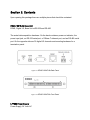
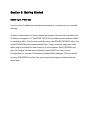
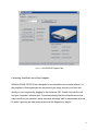
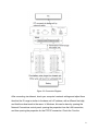
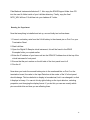
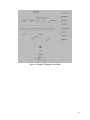
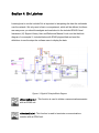
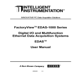
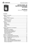
EDAS-1001E-2A Ethernet Data Acquisition System
User Guide
Data Acquisition and Control Systems – CDA 4170
J. Wesley Hulette & Matthew Coyne
Florida Gulf Coast University, Fort Myers FL
Section 1: Introduction
2
Section 2: Contents
2
EDAS-1001E-2A Base Unit
2
LPP002 Power Supply
2
EDAS-1004T-1 Panel
2
Other Hardware Items
2
EDAS-1001-2A CD
2
Section 3: Getting Started
2
Obtaining an IP Address
2
Connecting Your Base Unit to Your Computer
2
Installing the LabView Plugins
2
Running the Experiment
2
Section 4: On Labview
2
Section 5: Conclusion
2
References
2
2
Section 1: Introduction
Welcome to the EDAS-1001E-2A Ethernet Data Acquisition System. This user guide will
walk you through a simple experiment as a process to both test the hardware and to
learn the basics of understanding how to properly utilize it.
The EDAS-1001E-2A Ethernet Data Acquisition System is a kit that allows simple data
to be transmitted over a network. Data can be fed into it through 32 digital I/O ports.
Data can also be introduced through serial ports, but only with specialized devices built
to work with the kit.
This guide will define the materials you should have received in this kit, as well as
materials you may need. It will then give a walkthrough for our first experiment. Finally
this guide will explain how our experiment relates to future usage of the kit and help
explain how it worked.
Section 2: Contents
Upon opening this package there are multiple pieces that should be contained:
EDAS-1001E-2A Base Unit
EDAS, Digital I/O, Base Unit w/RS-232 and RS-485
The actual data acquisition hardware. On the back contains a power-on indicator, the
power input jack, an RS-232 serial port, a 10Base-T ethernet port, and an RS-485 serial
port. On the opposite side are 32 digital I/O channels and mounting hardware for a
termination panel.
Figure 2.1 EDAS-1001E-2A Back Panel
Figure 2.2 EDAS-1001E-2A Front Panel
LPP002 Power Supply
Power Supply, 24 Volts AC
90-120 Volts AC (60 Hz) input
The included power supply for the base unit hardware.
EDAS-1004T-1 Panel
Digital I/O Termination Panel
The termination panel is a a piece of hardware that mounts onto the the front of the
base unit. This panel makes the 32 digital I/O channels easily accessible.
Figure 2.3 EDAS-1004T-1 Termination Panel
For our experiment there are other parts that are also required, which may or may not
be included, please ensure you have these items before continuing:
5
Other Hardware Items
An RS-232 Serial Cable
A Crossover CAT-5 Ethernet Cable
A 9-Volt Battery
Battery Wires
EDAS-1001-2A CD
containing:
edas-hw.pdf - User manual for the hardware
EDAS User and Reference Manual.pdf - User manual for the Labview plugins
edas_lv12.zip - Zip folder containing an installer for the Labview plugins
Converted VI’s folder - Folder containing Labview plugins pre-converted to work within
newer versions of Labview
Errors.txt - List of error codes the software may report
Also included are various images of the hardware and software
6
Section 3: Getting Started
Obtaining an IP Address
If you know an IP address has already been assigned to your base unit, you may skip
this step.
In order to use the base unit over a network as intended, we must first know what local
IP address is assigned to it. This EDAS-1001E-2A kit includes various software utilities
for interfacing with it. The first one we will be using is the EDAS SYSCHECK utility. First
install SYSCHECK by by running edassys3.exe. Using your power supply and serial
cable, plug in your base unit and connect it to your computer. Run SYSCHECK and
open the Program tab and select a desired unused COM Port. In the Current
Configuration box, note the IP Address and Subnet Mask displayed. This is all we will
be using SYSCHECK for at this time, you may quit the program and disconnect the
serial cable.
Figure 3.1 SYSCHECK Program Tab
Connecting Your Base Unit to Your Computer
While the EDAS-1001E-2A kit is designed to be controlled over an entire network, for
the purposes of this experiment we recommend you simply connect your base unit
directly to your computer by plugging in the crossover CAT-5 cable into both the unit
and your computer’s ethernet port. Connecting directly like this minimizes errors that
may come from your network’s setup, because we simply wish to demonstrate how the
kit works, removing as many external errors at the beginning is helpful.
8
Figure 3.2 Connection Diagram
After connecting via ethernet, check your computer’s network settings and adjust them
thus that the IP range is similar to the base unit’s IP address, with a different final digit,
and that the subnet mask is the same. In Windows, this can be done by opening the
Network Connections control panel, opening the properties from the LAN connection,
and then opening the properties for that TCP/IP connection. Check the “Use the
9
following IP address” button and type in information matching the base unit, except
changing the final digit of the IP address.
Figure 3.3 Checking Your Network Properties
Installing the LabView Plugins
From the included CD, open the edas_lv12 zip file and run the setup.exe file. This
package installs various dll files for LabView, LabView plugins we require, and a few
example LabView Virtual Instruments, including the one we will be using. The default
folder these will be installed to is C:\LabView.
Unfortunately, this software is for an older version of Labview, we will have to make
some changes so everything runs smoothly. C:\LabView is no longer where LabView is
installed to, and the plugins need to be converted to work with current Labview versions.
We have included, on the CD, a folder titled Converted VI’s, these have the updated
versions of the VIs that you will need. Copy the EDAS Examples and EDAS Utilities
folders from the CD into your LabView installation folder, most likely at C:\Program
10
Files\National Instruments\Labview 8.*\. Also copy the EDAS Support folder from CD
into the user.lib folder inside of your LabView directory. Finally, copy the final
NPCI_W3V.dll from C:\LabView into your Labview 8.* folder.
Running the Experiment
Now that everything is installed and set up, we can finally test out hardware.
1. Connect one battery wire from the 9-Volt battery to the chassis pin on Port 0 on your
Termination Panel
2. Start LabView
3. Open the Digital IO Sample virtual instrument, this will be found in the EDAS
Examples folder you copied earlier.
4. Enter the IP address of your base unit into the EDAS IP Address box at the top of the
virtual instrument’s front panel
5. Ensure that the port number on the left side of the front panel is set to 0
6. Run the VI
Now when you touch the second battery wire to the numbered bits on Port 0 on the
termination board, the value in the Input Data box at the center of the VI’s front panel
should change. This box defaults to display in hexadecimal, but it can changed it so that
it displays in binary. You can do this by right-clicking on the input data box, selecting
properties, and changing the display format. If you do this you can see exactly which
pins are which bits and how you are effecting them.
11
Figure 3.4 Digital IO Sample Front Panel
12
Section 4: On Labview
Learning how to use the included VIs is important to interpreting the data this unit sends
over the network. We only used a few in our experiment, which will be defined, but there
are many more you should investigate and read about in the included EDAS Virtual
Instrument (VI) Support Library User and Reference Manual. Look over the the block
diagram of our sample VI, included below with EDAS plugins titled and read the
definitions to see the steps the software uses to display the data.
Figure 4.1 Digital IO Sample Block Diagram
nSessionBegin.vi - This function is used to initiate a communications session
with an EDAS unit.
nSessionEnd.vi - This function is used to terminate a communications
session with an EDAS unit.
nSWInit.vi - This function is used to initialize the Net Link drivers.
nSYSInquire.vi - This function is used to obtain ID and power cycle
information on a connected EDAS unit.
nVERInquire.vi - This function obtains version information about the
connected EDAS unit’s firmware.
nDIOConfigureList.vi - This function is used to configure (input or output) a
list of digital I/O ports.
nDIORead.vi - This function is used to read a digital input port.
14
Section 5: Conclusion
The EDAS-1001E-2A Ethernet Data Acquisition System is a simple toolset, and we
have completed just a simple experiment with it here. What have you accomplished this
experiment? Seemingly not much. We have changed only one bit at a time with our
battery. This information was then sent over the network by our system. Finally, it was
interpreted into something we could read by Labview.
But this simple facade betrays what can now be done by just extending the things we
have done here further. In future experimentation all three of those parts of our system
could be made grander.
The only data we looked at was if a battery was connected to a single bit. But by just
looking at the termination panel it becomes obvious that this is a gross underutilization
of the equipment at hand. Our system allows information to be sent from four ports of
eight bits each, for a total of 32 bits. This is a large amount of data, and multiple
different sensors could be connected at the same time.
For simplicities sake during this experiment we only directly connected the main unit
directly to the host computer. But that undermines the point of this system, that it is a
network device. In the future it could be connected to a large network, or even accessed
over the internet.
Our user interface inside of Labview was also rather utilitarian and purpose driven. In
further projects, with more complex data to interpret, this could be improved on as well.
While looking at a simple binary number is useful for seeing our bit flip when we plug in
the battery, it would not prove so helpful when trying to read the results given by a
temperature sensor or pressure meter.
At its core this unit is a simple transmission device, it takes in normal digital information
and sends it over a network, or even the entire Internet. You may have only flipped a
single bit today, but that bit is the start of a very useful device.
16
References
Bishop, R., Learning with Labview 8, Prentice Hall, Upper Saddle River, New Jersey,
2007
FactoryView EDAS-1000 Series Digital I/O and Multifunction Ethernet Data Acquisition
Systems EDAS User Manual, Intelligent Instrumentation Inc., Tucson, Arizona, 1997
EDAS Virtual Instrument (VI) Support Library For National Instruments LabVIEW
Software User and Reference Manual, Intelligent Instrumentation Inc., Tucson, Arizona,
1998