1
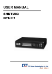
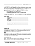
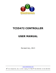
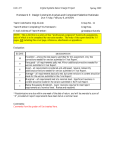
Swan™ CDM
Swan Designer User Manual
revision 1.0 • 12/2014
Product Overview
Swan CDM display products replace alphanumeric character displays and give
your product a fresh new look with no programming required. The module’s USB
interface updates the look of your product with full-color high resolution graphics
for custom logos and eye-catching image display, while the digital interface
provides compatibility with existing legacy systems and low-end microcontrollers.
Using this Document
This user manual’s first chapter steps through a product configuration example,
discussing only the configuration options and features being used. It serves as a
guide for those wanting a known-good example, and is also well-suited for those
who don’t have the software in-hand.
Those who have already experimented with the software may wish to skip to the
subsequent chapters, which discuss each configuration setting and program
feature in detail. This chapter also contains some elementary graphic design tips.
Finally, the appendix contains miscellaneous pertinent information such as
company contact information, references to other documents, and software
specifications.
Copyright
This document is copyrighted by The Chicago Firmware Factory with all rights
reserved. No part of this document may be reproduced in any form without prior
written consent of The Chicago Firmware Factory.
Copyright © 2014 The Chicago Firmware Factory. All rights reserved.
Patents
This product is subject to one or more patent(s) pending.
Disclaimer
This manual has been thoroughly reviewed for accuracy, and every effort has been
made to ensure that the information is accurate and complete. However, different
versions of this product have different features and capabilities, and this manual
only reflects one of those versions. Therefore, The Chicago Firmware Factory
assumes no responsibility for errors, omissions or defects in this material, and
shall not be liable for any damages resulting from their use.
The information in this document is subject to change without notice.
The Chicago Firmware Factory makes no warranty of any kind with respect to this
document, either expressed or implied, including without limitation any implied
warranties of merchantability or fitness for a particular purpose.
1
1 Quick Start
1.1 Overview
Using the Swan Designer software, you can create an attractive, professional, and
full-featured customer experience for your Swan™ CDM-based product in
minutes.
The software is used to customize the overall look and feel of the Swan CDM. The
software is used to configure static (unchanging) properties such as background
image, animations, brightness, and data interface. The software also configures
the look and feel of dynamic (changing) content such as font, color, position,
alignment, shadowing, and custom character images.
The software’s device programming features are suitable for programming one or
multiple Swan CDM displays in a production environment.
This chapter illustrates configuring the display for use in a typical application.
Because it serves only as an example, many configuration details are omitted or
left unexplained. Please refer to the Reference section for detailed information
about various configuration options.
1.2 Application Startup
The Swan Designer software is compatible with Microsoft Windows Vista,
Windows 7, and Windows 8. The software can be used with Windows XP if the
Microsoft .Net Framework version 3.5 or later is installed.
To use the software, no installation is necessary. Simply click the Swan Designer
icon to begin using the program.
Figure 1.1. Swan Designer application startup.
After startup, the Swan Designer application’s functions are categorized using
tabs. Initially, the application displays the “Background” tab.
Figure 1.2. Background Tab.
1.3 Select Background Image
Begin configuration by selecting a background image. Click the “Load Image”
button, then navigate to a folder containing the image shown in Figure 1.3 (this
image is available for download via the website).
Figure 1.3. Loaded background image.
The background image will be shown any time the Swan CDM module is on.
1.4 Set Up Text Options
The Swan CDM is designed to emulate a character display module. When text is
received by the Swan CDM, it can be formatted and positioned on the screen in an
attractive style that complements the background image and product marketing
guidelines.
Figure 1.4. Text Options tab.
Figure 1.4 shows the default Text Options tab. Click the “Line 1 Text” text or the
“Select Line 1” button to edit line 1’s properties.
Figure 1.5. Edit text line 1 properties.
Edit line 1’s properties to locate the text at X=240, Y=40, then change text
alignment to Centered in the “Alignment” dropdown list. Next, select the second
available font in the “Font” dropdown list, “Verdana Regular, 32.0 pt”. To ensure
the text is highly-visible against the background, select “Solid Outline” from the
“Shadow” dropdown list and set the “Depth” value to 1.
Each displayed line emulates a line shown using a character (dot matrix) LCD
display. Select a display RAM (DDRAM) address (“RAM Address” text box) and
line length (“Length” text box). In the example shown, a Lumex LCM-S02004DSF
display connected to a leading security alarm system is emulated.
Enter sample text (“Alarm Disabled” in this example) for line 1. This text is used
to emulate text that will eventually be sent from the host system and assess its
aesthetic qualities.
Figure 1.6. Line 1 properties edited.
Using Figure 1.7 as a guide, configure lines 2, 3, and 4 to be centered at X=240 with
font = “Verdana Regular, 26.0 pt” and “Verdana Regular, 18.0 pt”.
Figure 1.7. Line 1-4 properties configured for security alarm.
1.5 Review Fonts
The Fonts tab allows you to select a font and preview a string of sample text, as
well as inspect the font’s rendered characters.
Figure 1.8. Fonts Tab.
The Swan CDM allows up to 4 font/size combinations to be used. Then, replace
“Verdana Regular, 26.0 pt,” the first font in the list, with a different font by
clicking the “Change Font” button. A dialog box appears and allows selection of
font name, style, and size.
Figure 1.9. Font Selection Dialog.
1.6 Provide Custom Character Bitmaps
The custom characters tab allows you to specify bitmaps to be used in place of
character displays’ low-resolution programmed custom characters. To simplify
this quick start guide, skip this tab.
Figure 1.10. Custom Characters Tab.
1.7 Configure Other Options
The Other Options tab allows selection of foreground/background/transparency
colors, brightness behavior, and digital interface options.
The background image is predominately white, so foreground color can remain
black, and background color can be left white. Transparent color is not used in
this example.
Figure 1.11. Other Options Tab.
For this example, configure the interface for standalone mode by selecting
“Disabled / USB Only” from the Interface list, and checking “Power Up with
Display On”.
Figure 1.12. Interface Type and Power Up Mode.
Now that the display is set up, save the settings to a file. From the “File” menu,
click “Save As…” and specify a filename when prompted.
Figure 1.13. Saving the File.
To program the configuration into the display module, click the “Device
Programming” tab. The “Available Swan Display:” list is continuously updated
as display modules are plugged/unplugged from the computer’s USB port. In
most cases, only one display will appear in the list.
Figure 1.14. Device Programming Tab.
Ensure that the “Update background image only” and “Prompt for display
identifiers” check boxes are checked, the click the “Write To All” button to
program the display module. The “Data Transfer” progress window will be
shown during programming.
Figure 1.15. Device Programming In Progress.
2
2 Reference
2.1 Overview
Using the Swan Designer software, you can create an attractive, professional, and
full-featured customer experience for your Swan™ CDM-based product in
minutes.
The software is used to customize the overall look and feel of the Swan CDM. The
software is used to configure static (unchanging) properties such as background
image, animations, brightness, and data interface. The software also configures
the look and feel of dynamic (changing) content such as font, color, position,
alignment, shadowing, and custom character images.
The software’s device programming features are suitable for programming one or
multiple Swan CDM displays in a production environment.
This section gives as much detail as possible for each configuration option.
Configuration options are grouped by tabs for easy navigation and search.
2.2 Background Tab
Use the Background Tab functions to select an unchanging (static) image or solid
color for the display module.
Figure 2.1. Background Tab.
2.2.1 Clear Image button
Use the Clear Image button to return the background to a solid white background.
2.2.2 Use Solid Color button
Click the Use Solid Color button to replace the background with a solid
background filled with a specific color. After pressing the Use Solid Color button,
the Color dialog box is shown. Press OK to accept the selected color and fill the
background.
Figure 2.2. Background Color Selection.
2.2.3 Load Image button
Click the Load Image button to specify a background image to be displayed at all
times on the display module. After clicking the Load Image button, the Open
dialog box is shown, prompting for an image to be selected.
Bitmap, JPEG, GIF, PNG, and TIFF images formats are supported. Images are
scaled from their native size to 480×272 with 16 bit-per-pixel color (65536 colors).
For best results, select a 4×3 aspect-ratio input image with resolution higher than
480×272 resolution.
2.3 Text Options Tab
The Text Options Tab is used to configure the display’s up-to-four text lines,
including location, font, text alignment, shadow/outline, display RAM
address/length, and preview text.
Figure 2.3. Text Options Tab.
2.3.1 Show Disabled Lines check box
Un-check the “Show Disabled Lines” check box to hide preview text lines that will
not be shown on the display module (display RAM length=0). Once configured,
un-checking this check box gives a more accurate preview of the display module’s
configuration.
2.3.2 Preview line selection
To select and configure a preview text line, click the line or its corresponding
button (e.g. “Select Line 1”). When selected, the text line is outlined in red, and
configuration options for the given text line are shown and can be changed.
Figure 2.4. Configuring Preview Text Line 1.
2.3.3 Location (X, Y) text boxes
Use the location text boxes to specify X and Y coordinates, in pixels, for the
preview text line. Alternatively, the preview line can be moved using the mouse
or arrow keys, and its numeric coordinates will be updated in these boxes.
When text is left-aligned, the “X” coordinate specifies the leftmost edge of the
text’s bounding box. When centered, “X” specifies the center, and when rightaligned, “X” specifies the rightmost edge.
2.3.4 Alignment dropdown list
The alignment list specifies whether text will be left-aligned, centered, or rightaligned relative to the “X” coordinate specified.
2.3.5 Font dropdown list
The Font dropdown list configures the text line to use one of the four fonts
specified using the Fonts Tab (see section 2.4).
2.3.6 Shadow Type dropdown list
The Shadow Type dropdown list allows you to add an outline, full shadow, or
drop-shadow to text. Shadows are used to emphasize large text, or to help
distinguish text from a background image.
Solid Outline: Select “solid outline” to improve readability of text over a multicolored background. The text will be outlined using the “Background Color”
value chosen on the Other Options Tab (see section 2.6).
Figure 2.5. Solid outlined text against a complex background.
Shadow Outline: Select “shadow outline” for an effect more subtle than the solid
outline, which may be more pleasing against a solid background. The text will be
outlined using a color 75% between the “Background Color” value and
“Foreground Color” value chosen on the Other Options Tab (see section 2.6).
Figure 2.6. Shadow outlined text against a complex background.
Light from Top Left (and others): Select “Light from Top Left,” “Light from Top
Right,” and others to create a “drop shadow” effect using a color 75% between the
“Background Color” value and “Foreground Color” value chosen on the Other
Options Tab (see section 2.6). These are typically used against a solid background
to add depth and dimension to text.
Figure 2.7. Drop shadow against a white background.
2.3.7 Depth up/down control
Each shadow type has an associated depth value. While values higher than 1 are
rarely used, values up to 15 are available for use with very large text, unusual
fonts, or complex backgrounds. Selecting a large value can negatively affect text
rendering time.
Figure 2.8. Drop shadows with 1, 2, and 3 depth values.
2.3.8 RAM Address text box
Each text line has an associated starting address in the 256-byte display RAM
string buffer. When emulating a 2-line character display module, address values
of 0 and 64 are typical for lines 1 and 2. 0/32/64/96 are common for 4×20
character displays.
2.3.9 Length text box
In addition to a RAM address, each text line has an associated length value. When
emulating a character display module, the value for each line is set to the number
of display columns (e.g. 20 characters).
To disable (don’t display) a text line, set its length to zero.
2.3.10
Sample Text text box
For each line, example text can be entered to aid in text, graphics, and color layout.
This text is also shown on the display module when the “Preview Text” function is
used via the Device Programming tab (see section 0).
2.4 Fonts Tab
The Fonts tab is used to select up to four fonts for use in the Text Options tab (see
section 2.3). The Fonts tab also provides functions for previewing text as it will be
rendered, measuring memory usage of various fonts, and limiting a larger font to
a specified character range to save space.
Figure 2.9. Fonts Tab.
2.4.1 Available Fonts list box
The Available Fonts list box shows the currently-loaded set of four fonts. Each
row corresponds to one of the display’s four font “slots.” When a font is clicked,
the character preview images, and preview text are shown using the selected font.
2.4.2 Clear Font button
The Clear Font button, when clicked, unloads font data for the “slot” selected in
the Available Fonts list box, freeing font space and updating the “Font Space in
Use” gauge.
2.4.3 Change Font button
The Change Font button, when clicked, displays the Font dialog box. When a new
font and size is specified, and the OK button is clicked, the selected font “slot” is
loaded with new font data, and the “Font Space in Use” gauge is updated.
2.4.4 Font 4 Character Range text boxes
When font space is low, the largest font can be loaded into font 4 and its character
set can be limited to save space. For example, a font may only be needed for digit
display (ASCII 48 to 57 for characters 0 to 9) or lower-case letters may not be
needed (ASCII 32 to 96).
2.4.5 Whole Range button
The Whole Range button is used to restore the Font 4 Character Range text boxes
to their default values, specifying that all ASCII characters will be included in the
slot 4 font character set.
2.4.6 Text Preview text box
The Text Preview text box shows the currently-selected font in the Available Fonts
list box using a default or user-specified string of text. The default preview text
has been chosen to show every alphanumeric character in mixed cases.
2.4.7 Font Space In Use gauge
The Font Space In Use gauge shows the percentage of font space being used by the
rendered characters in all four font “slots.” As fonts are added and changed, this
value is updated. The “in use” value must be below 100% for a configuration file
to be written to the display module.
2.4.8 Total Text Height
The total number of height used by the enabled preview text lines on the Text
Options tab (see section 2.3) is updated as fonts are changed. Writing a too-tall
configuration to the display module will cause an error. Consult display module
documentation for this limit.
Figure 2.10. Too much font space in use, and total text is too high.
2.4.9 Character Preview list box
The Character Preview list box, when clicked, shows a rendered image (glyph) of
the character selected using the Available Fonts list box “slot” font. Clicking a
specific character displays the character at actual size and 200% of actual size.
Clicking a character in the list also displays width and height information for the
font glyph.
2.5 Custom Characters Tab
In the Custom Characters tab, images can be loaded that are displayed when a
display RAM location contains ASCII character values 0 to 15. Alternatively, these
images can be used to animate an area of the screen.
Figure 2.11. Custom Characters tab page with animation.
2.5.1 Load Image 1 button (and others)
The Load Image button, when clicked, displays the Open dialog. When an image
is selected via the Open dialog box, it is displayed in the Custom Character Images
list next to the corresponding Load Image button.
Bitmap, JPEG, GIF, PNG, and TIFF images formats are supported. Images are
scaled from their native size to 1024 pixels with 16 bit-per-pixel color (65536
colors). Typical 1024-pixel image formats are 32×32 or 48×16.
Custom character images are shown using transparency. Background image data
is displayed wherever the Transparent Color from the Other Options tab (see
section 2.6).
2.5.2 Load Multiple Images button
The Load Multiple Images button can be used to select up to 16 images at once
and add them, in order, to the Custom Character Images list. When the button is
clicked, an Open dialog is displayed, allowing multiple images to be selected.
When the Open button is clicked, a starting image location is specified via a
prompt.
2.5.3 Use Images for Animation check box
When checked, the Use Images For Animation check box enables on-screen
animation and displays relevant parameters for editing. When un-checked,
animations are not shown.
2.5.4 Location (X,Y) text boxes
The Location text boxes specify the top, left coordinate where the animation
sequence will be displayed on-screen.
2.5.5 Image Sequence text boxes
The Image Sequence text boxes specify the range of custom character images to be
used in the animation sequence. Specify 0 to 15 to use all images.
2.5.6 Frame Duration text box
The Frame Duration text box value specifies the length in milliseconds that each
image is displayed. When the value is changed, the total duration of the
animation sequence, in milliseconds, is calculated and shown. For example, a 16frame sequence (images 0-15) with a 16ms frame duration lasts 256 ms.
2.5.7 Pause text box
After each animation sequence is displayed, the Pause text box value specifies
how long (in milliseconds) the last animation sequence frame is shown before the
sequence is restarted.
Figure 2.12. Animation settings.
9
image
1
2
12
13
14
15
16
time (ms)
0
32 9 384 416 448 480 512
16
1
2
9
1000 1032 9
Figure 2.13. Animation timeline for Figure 2.12 example.
2.6 Other Options Tab
The Other Options tab contains foreground, background, and transparent colors,
backlight and brightness control, and digital interface selection options.
Figure 2.14. Other Options Tab.
2.6.1 Edit Foreground Color button
Foreground color is used when rendering text. For lighter backgrounds, black is
typically used for this color. White or another complementary color may be
specified for dark or colored backgrounds.
The Edit button for foreground color, when clicked, displays the Color dialog box.
When a color is chosen, it is displayed next to the Edit button.
2.6.2 Edit Transparent Color button
The transparent color is used when rendering custom character images. Pixels
from the custom character image with this specific color are replaced with the
background color. The default fuchsia color (red=255, green=0, blue=255) is often
used for its uncommon use in typical images.
The Edit button for transparent color, when clicked, displays the Color dialog box.
When a color is chosen, it is displayed next to the Edit button.
2.6.3 Edit Background Color button
The background color is typically set to the most common color in the background
image. It is used in solid outline shadows, and is used with the foreground color
to determine the color used in drop shadows.
The Edit button for background color, when clicked, displays the Color dialog
box. When a color is chosen, it is displayed next to the Edit button.
2.6.4 Brightness radio buttons
The Brightness radio buttons select one of two backlight brightness operating
modes. When “Use Fixed Brightness Value” is checked, a constant, fixed
brightness specified in the Brightness up/down box is always used (0=off,
100=100% on).
When “Use Vo Input Pin for Brightness” is checked, backlight brightness is
dynamically controlled using the voltage at the display module’s VO pin and the
gain and offset up/down box values. This is typically used to adjust brightness
linearly from a connected ambient light sensor.
2.6.5 Interface dropdown list
The Interface dropdown list selects the digital interface the display module will
use to receive character data. See the Swan CDM specification for further details
about these interface types.
HD44780-compatible parallel: display module emulates character display modules
with fewer than 128 characters.
Dual HD44780-compatible parallel: module emulates character display modules
with more than 127 characters. E1 signal causes writes to display RAM addresses
0-127. E2 signal causes writes to display RAM addresses 128-255.
NewHaven RS-232: module emulates RS-232 NewHaven™ display modules.
CrystalFontz RS-232: module emulates RS-232 CrystalFontz™ display modules.
Matrix Orbital RS-232: module emulates RS-232 Matrix Orbital display modules.
NewHaven SPI: module emulates SPI NewHaven™ display modules.
CrystalFontz SPI: module emulates SPI CrystalFontz™ display modules.
NewHaven I2C: module emulates I2C NewHaven™ display modules.
CrystalFontz I2C: module emulates I2C CrystalFontz™ display modules.
Matrix Orbital I2C: module emulates I2C Matrix Orbital display modules.
Disabled / USB-Only: module ignores the digital interface and receives text only via
the USB interface. This is typically used with the Power Up with Display On
checkbox checked.
2.6.6 Power Up with Display On check box
When checked, the display module’s backlight will always be enabled. When unchecked, the module must receive a “DISPLAY ON” command via USB or the
digital interface to enable its backlight.
2.7 Device Programming Tab
The Device Programming tab contains controls to view connected Swan CDM
displays, program display modules, and instantly update displayed preview text
on each module.
Figure 2.15. Device Programming Tab.
2.7.1 Available Swan Displays list box
The Available Swan Displays list box contains a real-time view of the display
modules connected to the host computer via USB. As modules are connected,
they appear in the list box. As modules are disconnected, they are removed from
the list box. Each Swan Display is shown using the port name assigned by
Microsoft Windows®, e.g. COM1, COM2, etc.
Each item in the Available Swan Displays list box can be checked (selected) and
write or preview operations can be performed on all selected displays.
2.7.2 Get Identifiers button
In addition to device port information, an identifier value can be written to each
display. This aids in locating displays when multiple devices are connected, or
when displays are connected to a different computer and are assigned different
port names by Windows.
2.7.3 Update Background Image Only check box
The Update Background Image Only check box, when checked, reprograms the
display background specified using the Background tab (see section 2.2), reducing
programming time by 50%. Font data, text options, custom characters, and other
settings are left unchanged.
2.7.4 Prompt for Display Identifiers check box
When the Prompt for Display Identifiers check box is checked, a prompt is
displayed before each display module is programmed and a new identifier string
can be entered. This is typically done once, as identifier values are retained when
modules are subsequently programmed.
2.7.5 Always Preview After Write check box
When the Always Preview After Write check box is checked, the display module’s
backlight will be enabled and preview text will be updated after a new
configuration is written. This facilitates a quick and convenient edit-programpreview development cycle when adjusting images and various display
parameters. Backlight and preview text are retained until they are overridden by
the digital interface port or power is lost (display is removed from USB).
2.7.6 Write to Selected button
When clicked, the Write to Selected button programs each display in the Available
Swan Displays list box that is selected (checked). When clicked, the Data Transfer
dialog appears for each selected display and shows progress during display
programming.
Figure 2.16. Device Programming In Progress.
2.7.7 Preview Text on Selected button
The Preview Text on Selected button enables each selected (checked) display’s
backlight and updates displayed text using the Sample Text value specified via the
Text Options tab (see section 2.3). The update is instant, and no Data Transfer
dialog is shown.
2.7.8 Write To All button
The Write To All button programs all displays shown in the Available Swan
Displays list box, regardless of whether they are selected (checked). It is
functionally equivalent to checking all Swan display check boxes and clicking the
Write To Selected button.
2.7.9 Preview Text On All button
The Preview Text On All button programs all displays shown in the Available
Swan Displays list box, regardless of whether they are selected (checked). It is
functionally equivalent to checking all Swan display check boxes and clicking the
Preview Text On Selected button.
3
3 Character
Display
Emulation
3.1 Overview
This section contains text line RAM address and length values used to emulate
popular character display modules. For all modules, text intended for on-screen
display is programmed into a display RAM buffer. HD44780-based character
displays use a 128-byte display RAM buffer. For displays with more than 128
characters (e.g. 4×80), the display may employ two 128-byte buffers using multiple
enable signals.
3.2 Detailed Example
To illustrate display RAM (sometimes referred to as DDRAM) character mapping,
consider the character display shown below:
Figure 3.1. A typical 2×16 character display module.
This module displays up to 32 characters, split into 2 lines. Line 1’s data is located
at Display RAM address 0 (00 hex), and characters at addresses 0 to 15 (00 to 0F
hex) are displayed on line 1. Characters at address 64 (40 hex) to 79 (4F hex) are
shown in line 2. Characters at addresses 16-63 and 80-127 are ignored by the
display.
Address Display RAM Data:
0 (00h)
T h
i
s
16 (10h)
32 (20h)
48 (30h)
64 (40h) l i
n e
L
80 (50h)
96 (60h)
112 (70h)
i
s
a
C
D
D
i
2
x
1
6
s
p
l
a
Figure 3.2. Display RAM (DDRAM) mapping for a 2×16 character display
module.
For this display, configure lines 1-4 as follows:
Line 1
Line 2
Line 3
Line 4
RAM Address
Length
RAM Address
Length
RAM Address
Length
RAM Address
Length
0
16
64
16
0 / any value
0 (disabled)
0 / any value
0 (disabled)
Figure 3.3. Text line configuration parameters to match sample 2×16
display.
Sample text can be input to match typical data shown on the display.
Figure 3.4. Configuring display line 2 to match sample 2×16 display.
y
3.2.1 Lumex® LCD-S01602DSF/A
16×2 character display with LED backlight. HD44780-compatible parallel bus
interface.
Line 1
Line 2
Line 3
Line 4
RAM Address
Length
RAM Address
Length
RAM Address
Length
RAM Address
Length
0
16
64
16
0 / any value
0 (disabled)
0 / any value
0 (disabled)
3.2.2 NewHaven® NHD‐‐0224 series
24×2 character display with LED backlight. HD44780-compatible parallel bus
interface.
Line 1
Line 2
Line 3
Line 4
RAM Address
Length
RAM Address
Length
RAM Address
Length
RAM Address
Length
0
24
64
24
0
0 (disabled)
0
0 (disabled)
3.2.3 Lumex® LCM-S02404DSF
24×2 character display with LED backlight. HD44780-compatible parallel bus
interface.
Line 1
Line 2
Line 3
Line 4
RAM Address
Length
RAM Address
Length
RAM Address
Length
RAM Address
Length
0
24
64
24
0
0 (disabled)
0
0 (disabled)
3.2.4 Lumex® LCM-S02004DSR
20×4 character display with LED backlight. HD44780-compatible parallel bus
interface.
Line 1
Line 2
Line 3
Line 4
RAM Address
Length
RAM Address
Length
RAM Address
Length
RAM Address
Length
0
20
64
20
20
20
84
20
3.2.5 Kyocera Optrex® C-51847 series
20×4 character display. HD44780-compatible parallel bus interface.
Line 1
Line 2
Line 3
Line 4
RAM Address
Length
RAM Address
Length
RAM Address
Length
RAM Address
Length
0
20
TBD
20
TBD
20
TBD
20
3.2.6 Kyocera Optrex® C-51850 series
40×2 character display. HD44780-compatible parallel bus interface.
Line 1
Line 2
Line 3
Line 4
RAM Address
Length
RAM Address
Length
RAM Address
Length
RAM Address
Length
0
40
64
40
0
0 (disabled)
0
0 (disabled)
3.2.7 NewHaven® NHD-0440 series
40×4 character display with LED backlight. Dual HD44780-compatible parallel
bus interface.
Line 1
Line 2
Line 3
Line 4
RAM Address
Length
RAM Address
Length
RAM Address
Length
RAM Address
Length
0
40
64
40
128
40
192
40
3.2.8 Lumex® LCM-S04004DSF
40×4 character display with LED backlight. Dual HD44780-compatible parallel
bus interface.
Line 1
Line 2
Line 3
Line 4
RAM Address
Length
RAM Address
Length
RAM Address
Length
RAM Address
Length
0
40
64
40
128
40
192
40
3.2.9 General-Purpose Configuration
This configuration can be useful for troubleshooting communications with
undocumented character display modules. Configure each text line with a small,
non-proportional font such as 11 pt Courier.
Line 1
Line 2
Line 3
Line 4
RAM Address
Length
RAM Address
Length
RAM Address
Length
RAM Address
Length
0
64
64
64
128
64
192
64
After using this configuration, it should be possible to determine usable text line
configuration parameters.
3.2.10
Other Displays
Please contact The Circuit Foundry for assistance in emulating any display not
included in this chapter.
4
4 Graphic
Design Tips
4.1 Overview
Graphic design is art, and therefore the attractiveness of a design is subjective.
However, some design guidelines and aesthetics are almost universally accepted.
Other guidelines improve the usefulness of displayed data or help avoid common
limitations in LCD/TFT display technologies.
This chapter details a few guidelines but is in no way an exhaustive list.
4.1.1 Avoid busy backgrounds under text
Areas with overlaid text should be solid color, or at least include minimal shapes
and figures that could distract from overlaid text or cause text to be
misinterpreted.
4.1.2 Maximize contrast between background imagery and text
The foreground color should be chosen to maximize luminance and/or hue
difference from the background area near the text.
4.1.3 Avoid mostly-black backgrounds
Very dark backgrounds, especially when placed near “deep” black items such as a
black plastic display bezel, can exaggerate a display’s lower contrast ratio, making
the black areas appear grey.
4.1.4 Use 50% of the screen area for text
Good display design balances the need for readable text and the attractiveness of
background imagery.
4.1.5 Avoid gradients between similar colors
Color or lightness gradients can add dimension to flat images. However, slow,
gradual gradients exaggerate color quantization that’s inherent in TFT displays,
producing banding in some color/brightness ranges.
4.1.6 Outline text that’s shown over a photographic background
A 1-pixel outline can greatly improve readability of text that’s shown over
multiple colors. If a background color is chosen to match the background image,
readability is improved without a noticeable difference.
4.1.7 Use subtle drop shadows
The drop shadow effect can add dimension to overly-thick text, but drop shadows
should be kept 1-2 pixels deep so shadows don’t become distracting.
4.1.8 Use the same font face for all text
In most cases, vary only the size of text, not its font. In cases where text size is
vastly different and text conveys different information, a second font may be
justified.
4.1.9 Use high contrast and solid colors if grayscale inversion is
an issue
Some LCDs can display radically different colors if viewed from an unusual angle,
such as a portrait-mode display being viewed from below. This issue can be
mitigated by using solid, cartoon-like background coloring and a high-contrast
foreground color.
5
5 Contact
Information
5.1 Contacting The Circuit Foundry
5.1.1 Websites
General information and ordering:
http://www.thecircuitfoundry.com
Swan CDM documentation:
http://www.swan-cdm.com
5.1.2 Mailing Address
The Circuit Foundry
201 Houston Street
Batavia, IL 60510
5.1.3 Phone
All inquiries:
(630) 454-4407
The Circuit Foundry is a division of The Chicago Firmware Factory.