1
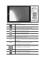
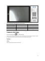
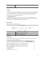
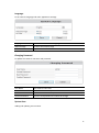
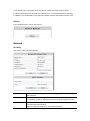
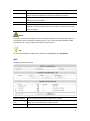
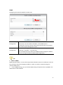
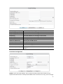
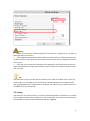
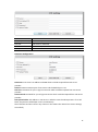
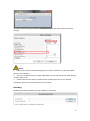
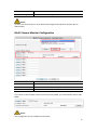
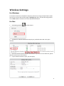
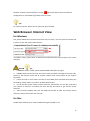
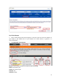
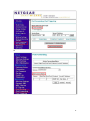
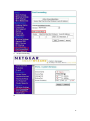
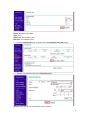
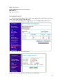
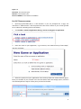
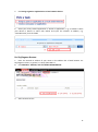
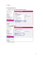
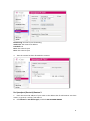
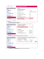
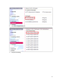
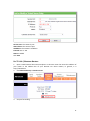
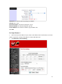
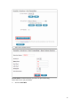
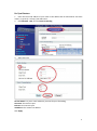
TENVIS Technology Co., LTD
User Manual
For MJPEG Cameras
Version 1.0.2
Catalogue
Basic Setup ................................................................................................................................ 4
Hardware Installation ........................................................................................................ 4
For Windows ...................................................................................................................... 4
Advanced Mode......................................................................................................... 4
LAN View.................................................................................................................... 6
For Mac ............................................................................................................................ 10
Basic Operation ....................................................................................................................... 10
For Internet Explorer ....................................................................................................... 10
For Other Non-IE Web Browsers ..................................................................................... 14
Camera Settings ....................................................................................................................... 15
System ............................................................................................................................. 15
About ....................................................................................................................... 15
PT Setting ................................................................................................................. 16
Backup and Restore Setup ....................................................................................... 17
NTP Setting .............................................................................................................. 17
Misc Setting ............................................................................................................. 18
System Log ............................................................................................................... 18
Language.................................................................................................................. 19
Changing Password .................................................................................................. 19
System User ............................................................................................................. 19
Update ..................................................................................................................... 20
Reboot ..................................................................................................................... 21
Network ........................................................................................................................... 21
IP Config ................................................................................................................... 21
WIFI.......................................................................................................................... 22
DDNS........................................................................................................................ 23
Alarm Setting ................................................................................................................... 24
Alarm Setting ........................................................................................................... 24
Email Setting ............................................................................................................ 24
FTP Setting ............................................................................................................... 27
Recording ................................................................................................................. 29
Multi Camera Monitor Configuration .............................................................................. 30
Wireless Settings ..................................................................................................................... 31
For Windows .................................................................................................................... 31
For Mac ............................................................................................................................ 31
Web Browser Internet View .................................................................................................... 33
For Windows .................................................................................................................... 33
For Mac ............................................................................................................................ 33
Mobile Phone View ................................................................................................................. 34
For LAN View ................................................................................................................... 34
For Internet View ............................................................................................................. 34
Attached List ............................................................................................................................ 35
2
3rd Party DDNS Settings ................................................................................................... 35
DynDns DDNS Settings............................................................................................. 35
NO-IP DDNS settings ................................................................................................ 37
Port Forwarding of Common Routers .............................................................................. 41
For 2wireRouter ....................................................................................................... 41
For Actiontec Routers .............................................................................................. 43
For Apple Airport Extreme or Time Capsule ............................................................ 44
For BT BTHomeHub Routers .................................................................................... 46
For D-link Routers .................................................................................................... 48
For FRITZ!! Routers .................................................................................................. 49
ForHuawei Routers .................................................................................................. 49
For Linksys W Series Routers ................................................................................... 50
For Movistar Routers ............................................................................................... 51
For Netgear Routers 1.............................................................................................. 51
For Netgear Routers 2.............................................................................................. 54
For Netgear Routers 3.............................................................................................. 56
For O2/ Thomson routers ........................................................................................ 57
For Sky/Sagmen Routers.......................................................................................... 58
For Speedport Routers 1.......................................................................................... 60
For Speedport (Deutsch) Routers 2 ......................................................................... 61
For TP-Link Routers 1 ............................................................................................... 64
For TP-Link / Binatone Routers ................................................................................ 65
For Virgin Routers 1 ................................................................................................. 66
For Virgin Routers 2 ................................................................................................. 67
For Webtell Routers ................................................................................................. 68
For Zyxel Routers ..................................................................................................... 71
Notice: Certain functions mentioned in this manual may vary according to camera's
model. For example, pan and tilt function are for Pan/Tilt enabled cameras only.
3
Basic Setup
This section will focus on connecting your IP camera, software installation and basic network
configuration. Other settings and operation will be explained in later chapters.
Notice:
For your security, please update the camera’s default password once you finish the following
procedure and you can turn to camera settings for reference.
Hardware Installation
Open the package. Mount the antenna (for cameras with detachable antenna). Connect the
camera to your router by a network cable and plug it in with the provided AC adapter.
For Windows
For basic installation, please turn to Page 2 of Quick Start Guide and follow the software IP
Camera Wizard step by step.
If you are familiar with IP camera or skilled in basic network configuration, you could also set
up the camera in advanced mode.
Advanced Mode
It will be much easier for you to set the camera LAN view and port forwarding in advanced
mode.
1. Double click the icon IP Camera Wizard.
2. Open the wizard and select advanced mode.
4
3. Advanced Mode Instructions
Current Computer information
5
Your computer’s network information is set for you to adjust the camera’s basic network
settings.
Network Card
Software will detect the network card connecting to Internet
automatically. If the appeared Network card is not the one you are
using, please correct it manually.
IP Address
Your computer’s IP address
Subnet Mask
Your computer’s subnet Mask
Gateway
Your computer’s Gateway
Current List
A list of the cameras in your local network
Mode
Camera’s series number. This user manual is for F series cameras
Name
Camera’s display name which is set to distinguish it from other
devices on your network
IP Address
Camera’s local network IP address that is used to view the camera
in the same local area network. Specify a unique IP address for
your network camera.
Camera Information
Name
HTTP port
IP Address
Sub Mask
Gateway
Inner URL
Outer URL
Camera’s display name which is set to distinguish with other
devices on your network
Camera’s communications port which is set to send video and
audio data
Camera’s local network IP address, which is used to view the
camera on the same local network. Specify a unique IP address for
your network camera.
Specify the mask for the subnet the network camera is located on
Specify the IP address of the default gateway (router) used for
connecting devices attached to different networks and network
segments
Camera’s LAN view URL. You can click Open to view the camera in
your local network
Camera’s remote view URL. You can click Open to view the camera
from Internet after you finish the following configuration
procedure.
LAN View
Click Open button of Inner URL and open the camera’s image from browser. Fill in the
camera’s username and password. Then you will get the live image of the camera. For the
further operation and configuration, please turn to the latter part of this user manual.
6
If it failed to connect to the camera via browser, please adjust the camera’s network setting.
1. Pick the correct network card in Current Computer information. Select your preferred IP
camera from the Current List. (The default IP address of TENVIS IP camera is 192.168.1.239)
2. Then modify the camera’s network setting in Camera Information.
3. If you are not sure how to modify the camera, please click One Key Set. IP Camera
Wizard will detect the computer’s network information and then modify the camera’s
network automatically.
4. Click Apply and then enter the camera’s username and password. The camera’s default
username is admin. There is no password by default, so leave the password field blank.
5. After clicking OK, you are able to view the camera in LAN after clicking Open.
7
Notice:
1. For Windows 7 users, if you could not find the IP Camera Wizard icon on the desktop
after installing the software, please search it in the Start menu.
2. If you could not find the camera from the list, please check the following the below
procedure.
a. Connect the camera to the router via network cable.
b. Disable the firewall and antivirus software of the computer such as AVG and McAfee.
Tips:
1. If your computer detects any virus when you download the searching software, the
reason is that the software has been regarded as the virus when it scans the devices in LAN.
We promise that there is no virus for the software downloaded from our official website or
in CD. Please rest assured.
2. Please disable your computer’s firewall and security software before you install the
software.
If One Key Set is not working, please set up IP address manually.
1. Click on Start, and then click on Control Panel.
2. Click Network and Sharing Center. The above is in Small icons view. If your screen looks
different, change by selecting Small icons from the View by drop-down menu in the top
right hand corner.
8
3. Find the connection connected to Internet and click the link.
4. Click Details
5. Find your PC’s IP address, Subnet Mask, Gateway and DNS.
9
Here are the details in the snapshot:
IP: 192.168.2.165
Subnet Mask: 255.255.255.0
Gateway: 192.168.2.2
6. Set up IP manually by the details above.
Copy the first 3 parts of IP address to camera’s IP and left the 4th part with its own.
Copy Subnet Mask and Gateway to IP camera’s Sub Mask and Gateway.
For Mac
For the LAN view of Mac, please refer to P8 of Quick Start Guide.
Basic Operation
This section will focus on basic operation of the interface including pan/tilt, video, audio, etc.
For Internet Explorer
After inputting the camera’s LAN or Internet access URL in IE browser, the camera’s
username and password will be required. The default username is admin. There is no
password by default, so leave the password field blank.
10
1. Select IE Active X Plug-in to download the IE plug-in and follow the procedure to install.
2. Select ActiveX Plug-in only for IE Browser
3. Click Allow to allow the web browser plug-in running in IE.
11
4.
Then you will see the live video and control panel
12
Instructions of the buttons of main panel
Return to the welcome page
Single camera view mode. For show back to single camera mode
from 4 camera view mode or 9 camera view mode.
4 camera view mode. After set up multiple camera settings, you
could view up to 4 cameras by this mode
9 camera view mode. After set up multiple camera settings, you
could view up to 9 cameras by this mode
Click this button for camera settings
Resolution
Video FPS
PT Speed
Changed the resolution of the video, there are 3 options:
640x480, 320x240 and 160x120.
Change the FPS of video, it means frames per second. The bigger
the number, the smoother the video is. Higher FPS depends on high
speed network.
Change the speed of the pan/tilt of the camera. There are 5
options: Fastest, Fast, Normal, Slower and Slowest.
(only available for the camera with Pan/Tilt)
There are 8 direction keys and the center button is rotation center.
(only available for the camera with Pan/Tilt)
The horizontal cruise will pan automatically
(only available for the camera with Pan/Tilt)
The vertical cruise will tilt automatically
(only available for the camera with Pan/Tilt)
13
Set preset position; this camera supports 6 preset positions.
What is a preset position? See tips below.
(only available for the camera with Pan/Tilt)
Go a specific preset position you have set
(only available for the camera with Pan/Tilt)
Invert the video horizontally
Invert the video vertically
Adjust the brightness of the video
Adjust the contrast of the video
Receive audio from the camera
(only available for the camera with 2-way audio)
Send audio to the camera
(only available for the camera with 2-way audio)
Take snapshot with the camera
Record video to PC, you can change the path in the settings menu
Tips:
What are preset positions?
Preset positions are IP camera's memorized P/T positions. Once you set a preset position,
you do not need to pan the camera to your preferred position. You simply press the preset
button that corresponds to the preset you want to see and the camera will move to that
position automatically.
For Other Non-IE Web Browsers
1. Select For Firefox, Google Chrome, etc for non-IE web browser. This mode is applicable
for Safari in Mac.
2. For other non-IE web browsers, there is a little difference.
14
Here are the details of the difference of the functions.
IE
Multiple Cameras Mode
√
2-way audio
√
Record to PC
√
Time Stamp
√
Non-IE web browser
×
×
×
×
Camera Settings
Click this Settings Button
for camera Settings.
Notice: Certain functions mentioned in this manual may vary according to camera's model.
For example, pan and tilt function are for Pan/Tilt enabled cameras only.
System
About
Basic Device Info & Customer Service info.
15
Device Model
Device SN
Hardware Version
Firmware Version
Manufacturer
Official Website
Contact Customer Service
Camera’s exact model
Camera’s serial number which is also the camera’ MAC address
Camera’s hardware version
Camera’s software version
TENVIS Technology Co., Ltd
http://www.tenvis.com
Consulting with TENVIS customer service if you have any
question about TENVIS IP camera.
Notice:
Customer Service information will be updated on the official website.
PT Setting
Camera’ Pan/Tilt and preset setting (only available for cameras with Pan/Tilt function).
Enable PT
Enable Preset Position
Turn the camera’s Pan/Tilt on/off
Turn the camera’s preset position on/off
16
Startup Position
Preset position that the camera will move to after rebooting
PT Speed
Speed for Pan/Tilt which is also the speed for preset movements
includes 5 speed options.
Backup and Restore Setup
Save or restore camera configuration.
Backup Configuration
Restore Backup
Configuration
Restore Factory
Setting
Keep the camera settings as a backup file. Download the appeared
box IPCamera_Settings.dat and save it on your computer in case
you need to restore your previous settings.
Click Browse to restore the backup settings which has been saved in
advance to restore the previous configuration.
Reset the camera to default factory settings
NTP Setting
Camera’s time setting
Current Time
Time Zone
NTP Server
Camera’s time and you can click Sync With Host to match it to your
computer’s time
Time zone of the place that the camera is located
Time server of the network which is connected with the camera
17
Automatic Calibration
Time Interval(by hour)
Intervals for the camera to correct the time with its own connected
network.
Tips:
1. Since the camera has no built in battery, the time saved in its memory may be lost when
the camera reboots and reset to 1970.01.01. This will not affect the alarm schedule, since
the exact alarm time will be synced from the Internet. You just need to reconnect the
network to correct the camera’s time manually.
2. What is NTP server?
NTP server is a server computer that reads the actual time from a reference clock and
distributes this information to its clients using network. Your camera will get the exact time
through an NTP sever by offering the time zone of its location.
Misc Setting
Camera’s some Miscellaneous Settings
Power line frequency
Power LED
Select the correct power frequency to avoid video flashing, adjust
the options, if your video flickering
The status of front green LED
System Log
You are able to check all the records for the computer operation of your camera starting
from when the camera was powered on.
18
Language
To set camera’s language and other appearance settings.
Language
Welcome Page
UI Color
To choose from 9 different languages
To select the welcome page
To pick the color for the whole interface
Changing Password
To update the camera’s username and password.
User Name
Current Password
New Password
Confirm Password
This camera’s username
To confirm the current password
To fill in the camera’s new password
Fill in the new password to confirm the change
System User
Adding and updating user accounts
19
Defined user contains three different user levels.
Different access is granted to different user levels as specified in the following sheet.
Live
Video
Record
Snapshots
Video
adjustment
Sound
Talkback
PT
operation
Settings
Admin
√
√
√
√
√
√
√
√
Operator
√
√
√
√
√
√
√
×
Guest
√
√
√
×
√
√
×
×
Tips:
PT operation is only available for cameras with Pan/Tilt.
Update
Update the device to the latest firmware version which can be found on our official website.
http://www.tenvis.com/download
Notice:
1. Please choose proper update package for your camera model (i.e. JPT 3815W).
2. Use an Ethernet cable NOT WI-FI to connect to your camera during the update process.
3. Make sure that the camera is not unplugged during the update process.
20
4. The whole process may take about 2-3 minute. Please wait until camera reboots.
5. Please update only with the help of a professional in case of problems while updating.
6. TENVIS is not responsible for any improper update attempts that lead to camera crash.
Reboot
Press reboot button to restart the camera.
Network
IP Config
The Camera’s Basic Network Settings
Device Name
DHCP
IP Address
Camera’s display name which is set to distinguish from other devices on
your network
Enable or disable obtaining IP address from DHCP server automatically. If
it is enabled, IP address and other items cannot be changed manually.
Camera’s local network IP address, which is used to view the camera in
the same local area network.
Specify a unique IP address for your network camera.
21
Net Mask
Default Gateway
DNS Server
Web Port
UPnP
Specify the mask for the subnet the network camera is located on
Specify the IP address of the default gateway (router) used for connecting
devices attached to different networks and network segments
DNS (Domain Name Service) provides the translation of host names to IP
addresses of your network
Camera’s communications port which is set to send video and audio data
Universal Plug and Play (UPnP) is an architecture for peer-to-peer
network connectivity and it will connect to the IP camera from Internet
more seamlessly
Notice:
As UPNP is also easily affected by router or firewall, sometimes it may show failed status. If
this happens, please forward the camera’s port on your router manually. Whether UPNP
succeeds or not, it will not affect the camera’s remote access.
Tips:
For the exact IP address configuration, please turn to P6-P10 of this User Manual.
WIFI
Configuring WI-FI connection
Wireless Network All the nearby wireless signals visible to the camera
Station Profile(Up Select the wireless signal and add it to Station Profile. Then you can
to 4)
switch your preferred wireless network easily.
WI-FI Link Status
Check and change wireless network status
For Set-up procedure please refer to Wireless Setup
22
DDNS
Configuring the camera’s DDNS for remote view
Built-in DDNS
Configuration
Third-party DDNS
Configuration
TENVIS IP Camera has been set with free default built-in DDNS
tenvis.info. You can enable or disable it. If the DDNS status is
“successful”, you can view the camera from Internet after you forward
the camera’s port through your router.
TENVIS camera supports third-party DDNS providers like Dyndns,
Araid.org,Zoneedit,no-ip and Oray.
You can request that we add a new DDNS provider through the TENVIS
Forum if you get third-party DDNS support agreement
Tips:
1. What is DDNS?
DDNS (Dynamic DNS) is a service that maps Internet domain names to IP addresses. Thus we
do not need to know the changing IP address in order to view the camera through the
relevant DDNS server.
2. For the DDNS settings, you can find the DDNS setting for Dyndns and no-ip DDNS in the
attached list of User Manual.
23
Alarm Setting
Alarm Setting
Motion Detection
Sensitivity
On-Screen Display
Warning Tone
Alarm Recording
Email Alarm
FTP Upload Folder
Back to Preset
Alarm Interval
(sec)
Schedule
Enable or disable the motion detection alarm
The sensitivity of the motion detection alarm which contains 5 levels.
Notice on the screen during motion detection alarm which is only
available in IE browser.
Alarm voice when the camera detects moving objects which is only
available for IE browser.
Records to the computer when the camera detects moving objects and
there is only IE browser supports this.
Sending alarm pictures to the specified email when the camera detects
the movements
Sending alarm pictures to FTP server set in advance when the camera
detects movement.
Moves camera to a preset position once the camera detects moving
objects (this is only available for Pan/Tilt IP camera).
Unit of time for periodic motion detection alarm which includes
picture and video alarm.
Specified motion detection period with 15 minutes a unit and one
week per cycle.
Email Setting
Once the motion detection alarm is enabled, camera will send snapshots to the specified
email when it detects the moving objects. There will be six emails per time and one picture
per email.
24
Sender([email protected])
Recipient[1]([email protected])
Recipient[2]
Recipient[3]
Recipient[4]
SMTP Server
SMTP Port (default 25)
Transport Layer Security
SMTP User
SMTP Password
IP Address Reported by Mail
Email address for sending the alarm email
1st email address for receiving the alarm email
2nd email address for receiving the alarm email
3rd email address for receiving the alarm email
4th email address for receiving the alarm email
Sending emails provider ‘s SMTP server address
Service port of SMTP server
Encryption protocol of SMTP Server
Sender email’s login username
Sender email’s login password
Sending the camera’s external access URL to the recipient’s
email
E-mail Alarm Configuration
Sender is your own email address. Since common email providers have a better service
experience and the built-in email provider SMTP servers are easier to set up, you are strongly
25
advised to use Gmail, Yahoo and other common email services as the sender email.
Recipient is the email to accept the email alerts and we suggest that you make it a different
email from the sender email.
SMTP Server: The SMTP (short for Simple Mail Transfer Protocol) works like a post assistant,
handling the sending of emails from the camera to an email server. SMTP Server receives
outgoing mail messages from users to the mail recipients they are intended for.
If your sender email provider is a public server, you can search the IP address of the email
provider’s SMTP server or DDNS from Google.
If your sender email provider is a private one, you can consult with the email provider’s
customer service.
SMTP Port: Service port of SMTP server which you can get with the above procedure
Transport Layer Security: Encryption protocol of SMTP Server and you can also get it from
the above procedure
SMTP User: The account you use to login to the SMTP server which is also the sender email
address
SMTP Password: The password you use to login to the SMTP server which is also the sender
email password
IP Address Reported by Mail: Once it is triggered, the latest external IP address will be sent
to recipient’s email as soon as the camera’s WAN IP address changes.
Then click Save and Test. Once it says Success that means the camera has set up e-mail
settings.
Go back to alarm settings and enable Email Alert to finfish the whole e-mail alert settings.
26
Notice:
1. Please check the basic network settings of the camera if it failed the test, go back to
Basic Operation for reference
2. There might be some delay for motion detection alarm since it is related to the network
condition and the service quality of the sender email’s provider. Thus it is beyond the control
of IP camera.
3. If you still can not receive any email alert after getting the test email, please check your
spam box and add your sender email address in the trust list of the recipient email once your
find it in spam.
Tips:
The email alert is sent via sender email’s provider server which is an SMTP server. Once the
camera signs in to the SMTP server, the email alert will be delivered to the recipient email
after getting SMTP server’s authentication. Therefore, the sender email, recipient email and
the SMTP server are all required.
FTP Setting
FTP, short for File Transfer Protocol, is used to transfer files between computers on a network.
You can upload camera’s alarm snapshots to your FTP storage. Thus, there is no need to keep
the computer on when the motion detection alarm is triggered.
27
FTP Server
FTP Port (default 21)
FTP User
FTP Password
FTP Upload Folder
FTP server’s address
FTP server’s port
FTP server’s username
FTP server’s password
FTP server’s subdirectory. Keep it blank if there is no subdirectory
FTP Alarm Configuration
FTP Server: FTP server’s IP address and DNS which could be required from FTP server
provider.
FTP Port: Communication port of FTP server and the default port is 21.
FTP User: Username for you to sign in FTP server which could be required from FTP server
provider.
FTP Password: Password for you to login FTP server which could be required from FTP server
provider.
FTP Upload Folder: File address in FTP server in which to save the alarm pictures. If it is left
blank, the pictures will be kept in FTP’s root directory.
Then click Save and Test. Once it says “Success” that means the camera has set FTP settings
successfully.
28
Go back to alarm settings and enable FTP Upload Folder to finfish the whole e-mail alert
settings.
Notice:
1. Please check the basic network settings of the camera if failed in test, go back to Basic
Operation for reference
2. FTP server is offered by FTP provider. TENVIS does not provide FTP service. Web Hosting
usually supports FTP.
3. Please make sure the camera is authorized to upload alarm pictures. For detailed
information, please consult with the FTP server provider.
Recording
Recording and alarm recording are only available for IE browser.
29
Recording Path
Alarm Recording Path
Camera’s destination folder to record to
Camera’s alarm recording destination folder
Notice:
If it does not work, please run IE as administrator. Right click IE browser and pick Run as
Administrator
Multi Camera Monitor Configuration
Device List in LAN
Alias:
IP Address: Port
User Name: Password
All MJPEG IP camera in your local network
Camera’s name
Camera’s IP address and port or you can fill in DDNS instead.
Camera’s username and password
If you want to view multiple cameras from Internet by DDNS, you could add the camera with
DDNS.
Notice:
This configuration is only available for IE browser.
30
Wireless Settings
For Windows
For wireless connection of Windows computer, please turn to Page 5 of Quick Start Guide.
You can also connect the wireless signal in Settings page after you view the image. Please
turn to Mac wireless connection for more detailed information.
For Mac
1.
Click Settings Button
and select Wi-Fi.
2. Click Rescan in Wireless Network and pick your preferred WI-FI SSID. Then press
Connect.
3. Fill in the relevant wireless network information. If you are not sure about this, please
keep the auto set-up of the camera.
4. If your wireless network is open, just pick Apply.
31
5. If your wireless encryption is WEP (SHARED), you need to select WEP Key Length & WEP
Key Entry Method. Please keep the auto set-up of the camera if you are not familiar with this.
Then enter the pass phrase and click Apply.
6. If your wireless encryption is WPA or WPA2, then select WPA Algorithms. Please keep
the auto set-up of the camera if you are not familiar with this. Then enter the pass phrase
and click Apply.
7.
Pick the wireless network added in Station Profile (Up to 4) and click Activate.
8.
Wireless network is connected if it appears
.
32
Wireless network is disconnected if it shows
. Please pick Edit to reset the network
configuration or pick Delete to get back to the first step.
Tips:
For security concern, please do not open your Wi-Fi network.
Web Browser Internet View
For Windows
First, please follow the IP camera wizard from step 1 to step 7. You can open the remote URL
in step 7 to view the camera from Internet.
If it failed in step 6, please refer to attached list and forward the camera’s port to the router
manually.
Notice&
Tips:
1. If DDNS still shows “failed”, please update DDNS to 8.8.8.8 to try again.
2. If DDNS shows succeed and you still cannot view the camera through the Internet URL,
please try the Internet access URL in another network since some routers do not support
loop-back.
3. If there are two or more routers and two or more WAN, there should be multi-time port
forwarding. Please contact your ISP or network administrator.
4. For 3G and 4G routers, please confirm with your ISP whether you are able to forward
your camera to Internet. It’s unlikely for most 3G and 4G routers to get Internet access
authority.
5. There is little possibility that your ISP might not be able to offer the Internet access
authority. Please confirm this with your ISP.
For Mac
Double check whether your camera’s DDNS setting succeeded or not.
33
If it appears failed, please refer to the IP address setting from Quick Start Guide and double
check DDNS. Once DDNS succeed, please forward your camera’s port manually by the help of
attached list of port forwarding. Then you could view the camera by the DDNS from Internet.
Notice&
Tips:
1. If DDNS still appears failed, please update DDNS to 8.8.8.8 to have a try.
2. If DDNS shows succeed and you still cannot view the camera through the Internet URL,
please try the Internet access URL in another network since some routers do not support
loop-back.
3. If there are two or more routers and two or more WAN, there should be multi-time port
forwarding. Please contact your ISP or network administrator.
4. For 3G and 4G routers, please confirm with your ISP whether you are able to forward
your camera to Internet. It’s unlikely for most 3G and 4G routers to get Internet access
authority.
5. There is little possibility that your ISP might not be able to offer the Internet access
authority. Please confirm this with your ISP.
Mobile Phone View
For LAN View
If your mobile phone’s network is the same with your camera’s, you can view the camera in
the local network.
Please see Quick Start Guide for the detailed information.
For Internet View
It is possible for you to view the camera from a different network which is usually other Wi-Fi
network or 3G, 4G and other network.
Once you set the remote view successfully on your computer, then you can input the
camera’s Internet Access URL in your mobile phone. Please turn to P11-P15 of Quick Start
Guide for detailed software installation.
34
Attached List
3rd Party DDNS Settings
DynDns DDNS Settings
1. Open www.dyndns.com in the browser.
2. Login directly if you have dyndns account. Register a new account if you do not have one.
3. Click Add Host Service
4. Register one DDNS account.
35
Hostname: DDNS for you to view the camera from Internet. You can select your preferred
dyndns and fill in your favorite hostname.
Service Type: Host with IP address
IP Address: Fill in the assigned IP address. This IP address is set only for registration and will
be updated after the IP address configuration.
Click Activate
5. DDNS configuration
36
DDNS Server: Dyndns.org
Account: Fill in Dyndns account you have set from the above procedure
Password: Enter Dyndns’ password
Click Save
6. Dyndns setup succeed.
NO-IP DDNS settings
1. Open www.no-ip.com in the browser.
2. Log in directly if you have no-ip account. Register a new account if you do not have one.
37
3. Click Add a Host
4. Register an account
38
Hostname: DDNS for you to view the camera from Internet. You can select your preferred
dyndns and fill in your favorite hostname.
Host Type: DNS Host (A)
Service Type: Host with IP address
IP Address: Fill in the assigned IP address. This IP address is set only for registration and will
be updated after the IP address configuration.
Click Create Host
39
5. DDNS configuration
DDNS Server: www.no-ip.com
Account: Fill in no-ip account you have set from the above procedure
Password: Enter no-ip ’s password
DDNS: Typed the DDNS Hostname for no-ip
Click Save
6. Configuration succeed
40
Port Forwarding of Common Routers
Before you set up port forwarding manually, please check 2 things before you do it.
1. Make sure you know the router’s brand, access URL, username and password. If you do
not know them, please get help from the provider of the router, such as your ISP.
2. Find your camera’s IP address and port. You can find them in your network
configuration.
The IP and port of the camera is very important for port forwarding.
For 2wireRouter
1. Open a web browser like Internet Explorer, Chrome, Firefox & etc. Enter the internal IP
address of your router in the address bar of your browser. The default URL is
http://192.168.1.1
2. Click the Firewall Settings button, and then click Add a new user-defined application
41
3.
Add a new user-defined application.
Application Name: It is just a name whatever you want for port forwarding,
Protocol: TCP
Port for range: port of the camera
Protocol timeout: 86400
Click Add.
4. Sign the application for the IP Camera
42
Select Computer
Select the IP camera in the list. You could choose the IP address or input the camera’s IP
address; it depends on the router’s model.
Select allow individual application
Select User-defined
Find your application you just added.
Click Add
For Actiontec Routers
1. Open a web browser like Internet Explorer or Chrome. Enter the internal IP address of
your router in the address bar of your browser. For theses routers, in general, it is
http://192.168.0.1
2. Click Advanced Port Forwarding
43
IP Port Range: The camera’s port.
Protocol: TCP
IP Address: The camera’s IP address.
Click Apply
For Apple Airport Extreme or Time Capsule
1. Go to your finder and type in Airport in the search bar and find your Airport Utility
program.
2. Find the Advanced Tab at the top and select it
3. Choose the Port Mapping option.
44
Add a service for IP camera.
Service: Choose a service
Public UDP Ports: the camera’s port
Public TCP ports: the camera’s port
Private IP Address: the camera’s IP address
Private UDP ports: the camera’s port
Private TCP ports: the camera’s port
Tips:
Be sure to click on the Update button after making these changes to upload them to your
Airport.
45
For BT BTHomeHub Routers
1. Open a web browser like Internet Explorer, Chrome, Firefox & etc. Enter the internal IP
address of your router in the address bar of your browser. For BT routers, in general, it is
http://192.168.1.254
2. Click Advanced Settings and Continue to Advanced Settings
3.
Click Supported Applications and Add new game or application
46
Game/Application name: It is just a name whatever you want for port forwarding,
Protocol: Any or TCP
Port Range: The port of the camera
4. Click Configuration; Select the application you just added in Game or Application List.
Select User Defended IP Address in the Device List.
Enter the camera’s IP address into Device IP Address.
47
For D-link Routers
1. Open a web browser like Internet Explorer or Chrome. Enter the internal IP address of
your router in the address bar of your browser. For D-link routers, in general, it is
http://192.168.0.1
2. Click Advanced - Virtual Server
Name: It is just a name whatever you want for port forwarding,
Public: the camera’s port
Private: the camera’s port
Protocol: TCP
Schedule: Always
48
Inbound Filter: Allow All
Click Save Settings
For FRITZ!! Routers
1. Open a web browser like Internet Explorer or Chrome. Enter the internal IP address of
your router in the address bar of your browser to login your camera. By default the IP
address should be set to http://192.168.178.1
2. Click the Internet link and then click Portfreigabe. In the portfreigabe, click Neue
Portfreigabe.
3.
Do port forwarding
Select Andere Anwendungen from the Portfreigabe aktiv fur drop down box.
Bezeichnung: A name, whatever you want
Protokoll: TCP
von Port: The camera’s port
bis Port:The camera’s port
an Computer: manuelle Eingabe der IP-Adresse
an IP-Adresse: The camera’s IP address
an Port: The camera’s port
ForHuawei Routers
1.
Enter the internal IP address of your router in the address bar of web browser. For these
49
routers, in general, it is http://192.168.1.1
2. Click Advanced - NAT, and click Port Mapping
Name: Whatever you want, it is just a name, e.g. TENVIS IP Camera
Public: the camera’s http port, e.g. 81
Private: the camera’s http port, e.g. 81
Protocol: TCP
Schedule: Always
Inbound Filter: Allow All
Click Save Settings
For Linksys W Series Routers
1. Enter the internal IP address of your router in the address bar of web browser. For these
Series routers, in general, it is http://192.168.1.1
2. Click Application & Gaming and click Single Port Forwarding
Application Game: It is just a name whatever you want for port forwarding,
External Port: the camera’s port
50
Internal Port: the camera’s port
Protocol: TCP
To IP address: the camera’s IP address
Enabled: Enable
For Movistar Routers
1. Enter the internal IP address of your router in the address bar of web browser. For these
routers, in general, it is http://192.168.1.1
2. Click Firewall - Port Forwarding
Comment: It is just a name whatever you want for port forwarding,
Public Port: the camera’s port
Local Port: the camera’s port
Remote IP Address: N/A
Local IP Address: the camera’s IP address
Click Add
For Netgear Routers 1
1. Enter the internal IP address of your router in the address bar of web browser. For these
routers, in general, it is http://192.168.1.254
2. Click Port Forwarding/Port Triggering or Port Forwarding. Select Port Forwarding and
select Add Custom Service
51
Or
52
3.
Do port forwarding
Or
53
Service Name: It is just a name whatever you want for port forwarding,
Starting Port: port of the camera
Ending Port: port of the camera
Service IP Address: IP of the camera
For Netgear Routers 2
1. Enter the internal IP address of your router in the address bar of your browser. For these
routers, in general, it is http://192.168.1.254
2. Click the Services link and Click Add Custom Service button.
3.
Add an IP camera service
54
Name: Whatever you want
Type: TCP
Start Port: The camera’s port
End Port: The camera’s port
4.
Click the Firewall Rules link; and then click the Inbound Services Add button.
5.
Add the user-defined IP Service in Inbound Services.
Service: Select the service you added in Service settings
55
Action: Allow always
Send to LAN Server: The IP of the IP Camera
Wan User: Any
Log: Always or None
For Netgear Routers 3
1. Enter the internal IP address of your router in the address bar of web browser. For these
routers, in general, it is http://192.168.1.254
2. Click the Port Forwarding / Port Triggering link and Click Add Custom Service button.
3.
Add a customer service for the camera
Name: It is just a name, whatever you want for port forwarding,
56
Type: TCP
Start Port: The camera’s port
End Port: The camera’s port
Server IP Address: The camera’s IP address
For O2/ Thomson routers
1. Open http://192.168.1.254 in a web browser. If you are prompted for a login, the
username is "Administrator" and the password is the serial number of your router (printed
on its underside, excluding the bit in brackets).
2. Click Toolbox > Game & Application Sharing > Create a new game or application.
3. Enter the name of your application, e.g. IP Camera, click "Manual Entry of Port Maps",
and then click Next.
4. Select the protocol of your application from the drop down list under Protocol option.
Enter port number of your camera in the two text boxes under Port Range option, and then
click Add. Repeat this step for all the ports you need to forward.
57
5.
Click Assign a game or application to a local network device.
6. Select your newly created application in "Game or Application", e.g. “IP Camera” select
your device in Device or select User Define and input the camera’s IP address, e.g.
“192.168.1.239”, then click Add.
For Sky/Sagmen Routers
1. Enter the internal IP address of your router in the address bar of web browser. For
Sky/Sagmen routers, in general, it is http://192.168.0.1
2. Click SECURITY - SERVICE, and click ADD CUSTOM SERVICE
3.
Add a Custom Service
58
Name: It is just a name whatever you want for port forwarding,
Start Port: the camera’s port
Finish Port: the camera’s port1
Type: TCP
Click APPLY
4. Click SECURITY - FIREWALL RULES - INBOUND SERVICE, add the service to the camera
Service: Select the service you just added.
Action: ALLOW always
Send to LAN Server: The camera’s IP address
WAN Users: Any
Log: Never
59
Click APPLY
For Speedport Routers 1
1.
Login your router. Click Netzwerk and NAT & Portregeln.
2.
Click Neue Regel anlegen
3.
Set port forwarding.
60
Bezeichnung: A name for port forwarding
IP-Adresse: The camera’s IP address
Protokoll: TCP
Ports: The camera’s port
Ports: The camera’s port
4.
Then the camera has been forwarded to Internet.
For Speedport (Deutsch) Routers 2
1. Enter the internal IP address of your router in the address bar of web browser. For these
routers, in general, it is http://192.168.1.1
2. Click Netzwert - Nat & Portregeln, and click ADD CUSTOM SERVICE
61
3.
Click PCs ubernehmen & freigeben
4.
Find your IP camera here and Add PC-Name to the camera
5.
Click SECURITY - FIREWALLRULES, add the service to the camera
62
6.
Select Neue Regel definieren
7.
Set port forwarding
63
Bezeichnung: It is just a name whatever you want for port forwarding
Gultig fur PC: Select the camera you just added
TCP: The camera’s port
For TP-Link Routers 1
1. Enter the internal IP address of your router in the address bar of your browser. For
TP-link routers, in general, it is http://192.168.1.1
2. Click Forwarding - Virtual Servers
3.
Set port forwarding
64
Service Port: the camera’s port
Internal Port: the camera’s port
IP Address: the camera’s IP address
Protocol: ALL or TCP
Status: Enabled
Click Save
For TP-Link / Binatone Routers
1. Open a web browser like Internet Explorer or Chrome. Enter the internal IP address of
your router in the address bar of your browser. For these routers, in general, it is
http://192.168.1.1
2. Click Advanced Setup - Virtual Servers
3.
Set port forwarding
65
Application: A name for port forwarding, e.g. TENVIS
Protocol: ALL or TCP
Start Port Number: the camera’s http port, e.g. 81
End Port Number: the camera’s http port, e.g. 81
Local IP Address: the camera’s IP address, e.g.192.168.1.239
Click Save
For Virgin Routers 1
1. Enter the internal IP address of your router in the address bar of web browser. For these
routers, in general, it is http://192.168.0.1 or http://192.168.0.254
2. Click Advanced - Port Forwarding
66
Name: A name whatever you want for port forwarding
Start Port: the camera’s port
End Port: the camera’s port
Local IP Address: the camera’s IP address
Click Add
For Virgin Routers 2
1. Enter the internal IP address of your router in the address bar of web browser. For these
routers, in general, it is http://192.168.0.1
2. Click Advanced Settings
3.
Select Port Forwarding
4.
Set Port Forwarding
67
Name: A name whatever you want for port forwarding
Start Port: the camera’s port
End Port: the camera’s port
Protocol: TCP
IP Address: the camera’s IP address
Click Add Rule
For Webtell Routers
1. Enter the internal IP address of your router in the address bar of web browser. For these
routers, in general, it is http://192.168.200.1
2. Click Security - Service - Port Forwarding
3.
Click new custom service
68
4.
Add a new custom service
Service Name: A name whatever you want for port forwarding
Select the service you just added.
5. And click static NAT
69
6.
Enter the IP address of the camera, click Enable.
70
For Zyxel Routers
1. Enter the internal IP address of your router in the address bar of web browser. For these
routers, in general, it is http://192.168.1.254
2. Click Network - NAT, and click Port Forwarding
3.
Add a new rule
Service Name: It is just a name whatever you want for port forwarding
Start Port: the camera’s port
End Port: the camera’s port
IP Address: The camera’s IP address
Click Apply
71