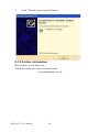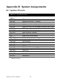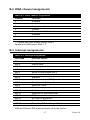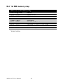
1
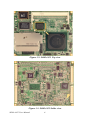
SOM-4455 ETX Module
AMD Geode LX series SOM-ETX
CPU Module with VGA/LCD/LVDS/
LAN interface
User Manual
Copyright notice
This document is copyrighted, 2002, by Advantech Co., Ltd. All rights
are reserved. The original manufacturer reserves the right to make
improvements to the products described in this manual at any time without notice.
No part of this manual may be reproduced, copied, translated or transmitted in any form or by any means without the prior written permission of
the original manufacturer. Information provided in this manual is
intended to be accurate and reliable. However, the original manufacturer
assumes no responsibility for its use, nor for any infringements upon the
rights of third parties which may result from its use.
Acknowledgements
SOM and DTOS are trademarks of Advantech Co., Ltd. AMD is a trademark of Advanced Micro Devices, Inc. Award is a trademark of Award
Software International, Inc. Cyrix is a trademark of Cyrix Corporation.
IBM, PC/AT, PS/2 and VGA are trademarks of International Business
Machines Corporation. Intel and Pentium are trademarks of Intel Corporation.
Microsoft Windows® is a registered trademark of Microsoft Corp. RTL is
a trademark of Realtek Semiconductor Co., Ltd.
C&T is a trademark of Chips and Technologies, Inc.
UMC is a trademark of United Microelectronics Corporation. Winbond is
a trademark of Winbond Electronics Corp.
STPC is a trademark of SGS Thomson Corp.
For more information on this and other Advantech products, please visit
our website at: http://www.advantech.com
For technical support and service, please visit our support website at:
http://www.advantech.com/support
Part No. 2006445500
1st Edition Printed in Taiwan May 2006
SOM-4455 User Manual
ii
Packing list
Before you begin installing your card, please make sure that the following
materials have been shipped:
• 1 SOM-4455 System On Module CPU module
• CD-ROM or Disks for utility, drivers, and manual (in PDF format)
• Heatsink
If any of these items are missing or damaged, contact your distributor or
sales representative immediately.
iii
Product Warranty (1 year)
Advantech warrants to you, the original purchaser, that each of its products will be free from defects in materials and workmanship for one year
from the date of purchase.
This warranty does not apply to any products which have been repaired or
altered by persons other than repair personnel authorized by Advantech,
or which have been subject to misuse, abuse, accident or improper installation. Advantech assumes no liability under the terms of this warranty as
a consequence of such events.
Because of Advantech’s high quality-control standards and rigorous testing, most of our customers never need to use our repair service. If an
Advantech product is defective, it will be repaired or replaced at no
charge during the warranty period. For out-of-warranty repairs, you will
be billed according to the cost of replacement materials, service time and
freight. Please consult your dealer for more details.
If you think you have a defective product, follow these steps:
1.
Collect all the information about the problem encountered. (For
example, CPU speed, Advantech products used, other hardware
and software used, etc.) Note anything abnormal and list any
onscreen messages you get when the problem occurs.
2.
Call your dealer and describe the problem. Please have your manual, product, and any helpful information readily available.
3.
If your product is diagnosed as defective, obtain an RMA (return
merchandise authorization) number from your dealer. This allows
us to process your return more quickly.
4.
Carefully pack the defective product, a fully-completed Repair and
Replacement Order Card and a photocopy proof of purchase date
(such as your sales receipt) in a shippable container. A product
returned without proof of the purchase date is not eligible for warranty service.
5.
Write the RMA number visibly on the outside of the package and
ship it prepaid to your dealer.
SOM-4455 User Manual
iv
Declaration of Conformity
CE
This product has passed the CE test for environmental specifications. Test
conditions for passing included the equipment being operated within an
industrial enclosure. In order to protect the product from being damaged
by ESD (Electrostatic Discharge) and EMI leakage, we strongly recommend the use of CE-compliant industrial enclosure products.
FCC Class B
Note: This equipment has been tested and found to comply with the limits
for a Class B digital device, pursuant to part 15 of the FCC Rules. These
limits are designed to provide reasonable protection against harmful
interference in a residential installation. This equipment generates, uses
and can radiate radio frequency energy and, if not installed and used in
accordance with the instructions, may cause harmful interference to radio
communications. However, there is no guarantee that interference will
not occur in a particular installation. If this equipment does cause harmful
interference to radio or television reception, which can be determined by
turning the equipment off and on, the user is encouraged to try to correct
the interference by one or more of the following measures:
• Reorient or relocate the receiving antenna.
• Increase the separation between the equipment and receiver.
• Connect the equipment into an outlet on a circuit different from that to
which the receiver is connected.
• Consult the dealer or an experienced radio/TV technician for help.
Caution!
Achtung!
There is a danger of a new battery exploding if it
is incorrectly installed. Do not attempt to
recharge, force open, or heat the battery.
Replace the battery only with the same or equivalent type recommended by the manufacturer. Discard used batteries according to the
manufacturer’s instructions.
v
Technical Support and Assistance
Step 1. Visit the Advantech web site at www.advantech.com/support
where you can find the latest information about the product.
Step 2. Contact your distributor, sales representative, or Advantech's customer service center for technical support if you need additional
assistance. Please have the following information ready before
you call:
- Product name and serial number
- Description of your peripheral attachments
- Description of your software (operating system, version, application software, etc.)
- A complete description of the problem
- The exact wording of any error messages
Document Feedback
To assist us in making improvements to this manual, we would welcome
comments and constructive criticism. Please send all such writing to: [email protected]
Safety Instructions
1.
Read these safety instructions carefully.
2.
Keep this User's Manual for later reference.
3.
Disconnect this equipment from any AC outlet before cleaning.
Use a damp cloth. Do not use liquid or spray detergents for cleaning.
4.
For plug-in equipment, the power outlet socket must be located
near the equipment and must be easily accessible.
5.
Keep this equipment away from humidity.
6.
Put this equipment on a reliable surface during installation. Dropping it or letting it fall may cause damage.
7.
The openings on the enclosure are for air convection. Protect the
equipment from overheating. DO NOT COVER THE OPENINGS.
8.
Make sure the voltage of the power source is correct before connecting the equipment to the power outlet.
9.
Position the power cord so that people cannot step on it. Do not
place anything over the power cord.
10.
All cautions and warnings on the equipment should be noted.
SOM-4455 User Manual
vi
11.
If the equipment is not used for a long time, disconnect it from the
power source to avoid damage by transient overvoltage.
12.
Never pour any liquid into an opening. This may cause fire or electrical shock.
13.
Never open the equipment. For safety reasons, the equipment
should be opened only by qualified service personnel.
14.
If one of the following situations arises, get the equipment checked
by service personnel:
a. The power cord or plug is damaged.
b. Liquid has penetrated into the equipment.
c. The equipment has been exposed to moisture.
d. The equipment does not work well, or you cannot get it to work
according to the user's manual.
e. The equipment has been dropped and damaged.
f. The equipment has obvious signs of breakage.
15.
DO NOT LEAVE THIS EQUIPMENT IN AN ENVIRONMENT
WHERE THE STORAGE TEMPERATURE MAY GO BELOW 20° C (-4° F) OR ABOVE 60° C (140° F). THIS COULD DAMAGE THE EQUIPMENT. THE EQUIPMENT SHOULD BE IN A
CONTROLLED ENVIRONMENT.
16.
CAUTION: DANGER OF EXPLOSION IF BATTERY IS
INCORRECTLY REPLACED. REPLACE ONLY WITH THE
SAME OR EQUIVALENT TYPE RECOMMENDED BY THE
MANUFACTURER, DISCARD USED BATTERIES ACCORDING TO THE MANUFACTURER'S INSTRUCTIONS.
The sound pressure level at the operator's position according to IEC 7041:1982 is no more than 70 dB (A).
DISCLAIMER: This set of instructions is given according to IEC 704-1.
Advantech disclaims all responsibility for the accuracy of any statements
contained herein.
Wichtige Sicherheishinweise
1.
1. Bitte lesen sie Sich diese Hinweise sorgfältig durch.
2.
Heben Sie diese Anleitung für den späteren Gebrauch auf.
3.
Vor jedem Reinigen ist das Gerät vom Stromnetz zu trennen. Verwenden Sie Keine Flüssig-oder Aerosolreiniger. Am besten dient
ein angefeuchtetes Tuch zur Reinigung.
vii
4.
Die NetzanschluBsteckdose soll nahe dem Gerät angebracht und
leicht zugänglich sein.
5.
Das Gerät ist vor Feuchtigkeit zu schützen.
6.
Bei der Aufstellung des Gerätes ist auf sicheren Stand zu achten.
Ein Kippen oder Fallen könnte Verletzungen hervorrufen.
7.
Die Belüftungsöffnungen dienen zur Luftzirkulation die das Gerät
vor überhitzung schützt. Sorgen Sie dafür, daB diese Öffnungen
nicht abgedeckt werden.
8.
Beachten Sie beim. AnschluB an das Stromnetz die AnschluBwerte.
9.
Verlegen Sie die NetzanschluBleitung so, daB niemand darüber
fallen kann. Es sollte auch nichts auf der Leitung abgestellt werden.
10.
Alle Hinweise und Warnungen die sich am Geräten befinden sind
zu beachten.
11.
Wird das Gerät über einen längeren Zeitraum nicht benutzt, sollten
Sie es vom Stromnetz trennen. Somit wird im Falle einer Überspannung eine Beschädigung vermieden.
12.
Durch die Lüftungsöffnungen dürfen niemals Gegenstände oder
Flüssigkeiten in das Gerät gelangen. Dies könnte einen Brand bzw.
elektrischen Schlag auslösen.
13.
Öffnen Sie niemals das Gerät. Das Gerät darf aus Gründen der elektrischen Sicherheit nur von authorisiertem Servicepersonal geöffnet werden.
14.
Wenn folgende Situationen auftreten ist das Gerät vom Stromnetz
zu trennen und von einer qualifizierten Servicestelle zu überprüfen:
a - Netzkabel oder Netzstecker sind beschädigt.
b - Flüssigkeit ist in das Gerät eingedrungen.
c - Das Gerät war Feuchtigkeit ausgesetzt.
d - Wenn das Gerät nicht der Bedienungsanleitung entsprechend funktioniert oder Sie mit Hilfe dieser Anleitung keine Verbesserung erzielen.
e - Das Gerät ist gefallen und/oder das Gehäuse ist beschädigt.
f - Wenn das Gerät deutliche Anzeichen eines Defektes aufweist.
15.
VOSICHT: Explisionsgefahr bei unsachgemaben Austausch der
Batterie.Ersatz nur durch densellben order einem vom Hersteller
SOM-4455 User Manual
viii
empfohlene-mahnlichen Typ. Entsorgung gebrauchter Batterien
navh Angaben des Herstellers.
16.
ACHTUNG: Es besteht die Explosionsgefahr, falls die Batterie auf
nicht fach-männische Weise gewechselt wird. Verfangen Sie die
Batterie nur gleicher oder entsprechender Type, wie vom Hersteller
empfohlen. Entsorgen Sie Batterien nach Anweisung des Herstellers.
Der arbeitsplatzbezogene Schalldruckpegel nach DIN 45 635 Teil 1000
beträgt 70dB(A) oder weiger.
Haftungsausschluss: Die Bedienungsanleitungen wurden entsprechend
der IEC-704-1 erstellt. Advantech lehnt jegliche Verantwortung für die
Richtigkeit der in diesem Zusammenhang getätigten Aussagen ab.
Safety Precaution - Static Electricity
Follow these simple precautions to protect yourself from harm and the
products from damage.
1.
To avoid electrical shock, always disconnect the power from your
PC chassis before you work on it. Don't touch any components on
the CPU card or other cards while the PC is on.
2.
Disconnect power before making any configuration changes. The
sudden rush of power as you connect a jumper or install a card may
damage sensitive electronic components.
ix
SOM-4455 User Manual
x
Contents
Chapter
1 Introduction ..................................................... 2
1.1
1.2
Chapter
Chapter
Specifications .................................................................... 3
1.1.1
1.1.2
1.1.3
1.1.4
Standard System On Module functions ......................... 3
Local-bus VGA interface ............................................... 3
Ethernet function ............................................................ 3
LVDS (Low Voltage Differential Signal) interface
(SOM-4455FL only) 4
1.1.5 Audio function ............................................................... 4
1.1.6 TV-out function ............................................................. 4
1.1.7 Mechanical and environmental ...................................... 4
Board dimensions.............................................................. 5
Figure 1.1:SOM-4455 dimensions ................................ 5
Figure 1.2:SOM-4455 Top view ................................... 6
Figure 1.3:SOM-4455 Solder view ................................ 6
2 Connector Assignments .................................. 8
2.1
Connector Locations ......................................................... 8
2.2
Pin Assignments for X1, X2, X3, X4 connectors ............. 8
Figure 2.1:SOM-4455 Locating Connectors ................. 8
3 Software Configuration ................................ 10
3.1
3.2
Introduction ..................................................................... 10
Utility CD disk ................................................................ 10
3.3
VGA display software configuration .............................. 10
3.4
Connections for two standard LCDs ............................... 12
Figure 3.1:Contents of SOM-4455 utility disk ............ 10
Figure 3.2:BIOS VGA setup screen ............................ 11
3.4.1
3.4.2
Chapter
4 PCI Graphic Setup........................................ 16
4.1
4.2
4.3
Chapter
Connections for Toshiba (640 x 480TFT color LCD) . 12
Table 3.1:Connections for Toshiba LTM10C042 ........ 12
Connections for Toshiba (800 x 600 TFT color LCD) 13
Table 3.2:Connections for Toshiba LTM12C275A ..... 13
Introduction ..................................................................... 16
4.1.1
4.1.2
4.1.3
Chipset ......................................................................... 16
Display memory ........................................................... 16
Display types ................................................................ 16
Installation of the PCI Graphic driver ............................. 16
4.2.1
Installation for Windows XP ....................................... 17
Further Information ......................................................... 20
5 Audio Setup.................................................... 22
5.1
5.2
Introduction ..................................................................... 22
Driver installation............................................................ 22
5.2.1
Before you begin .......................................................... 22
xi
Table of Contents
Chapter
6 PCI Bus Ethernet Interface.......................... 28
6.1
6.2
6.3
Chapter
6.3.1
6.3.2
Installation for Windows XP ....................................... 29
Further information ...................................................... 32
7 AES Driver Installation ................................ 34
7.1
Chapter
Introduction ..................................................................... 28
Features ........................................................................... 28
Installation of Ethernet Driver......................................... 28
Driver Installation ........................................................... 34
7.1.1
7.1.2
Before you begin .......................................................... 34
Further information ...................................................... 36
8 PCI Bridge ..................................................... 38
8.1
Driver Installation ........................................................... 38
8.1.1
8.1.2
Before you begin .......................................................... 38
Further information ...................................................... 40
Appendix A Prog. Watchdog Timer ................................. 42
A.1
Watchdog programming.................................................. 42
Appendix B System Assignments ...................................... 46
B.1
System I/O ports.............................................................. 46
B.2
DMA channel assignments.............................................. 47
B.3
Interrupt assignments ...................................................... 47
B.4
1st MB memory map....................................................... 48
Table B.1:System I/O ports ......................................... 46
Table B.2:DMA channel assignments ......................... 47
Table B.3:Interrupt assignments .................................. 47
Table B.4:1st MB memory map .................................. 48
Appendix C LVDS Connection.......................................... 50
C.1
C.2
LVDS Introduction.......................................................... 50
LVDS Pin assignments.................................................... 51
SOM-4455 User Manual
Table C.1:LVDS Pin assignments ............................... 51
Table C.2:Connector X3 .............................................. 52
xii
CHAPTER
1
2
General Information
This chapter gives background information on the SOM-4455 CPU System
On Module.
Sections include:
• Introduction
• Specifications
• Board Dimensions
Chapter 1 Introduction
Advantech's SOM-ETX form factor System On Module provides a scalable solution that meets customers' advanced CPU and application development needs. The SOM-4455 incorporates a low power, fanless AMD
Geode LX800-500 MHz processor that has become the embedded integrators' processor of choice. It uses a AMD CS5536 chipset as its VGA/
LCD controller, with single 18 bit LVDS interface and 64-bit graphics
engine. The CS5536 display controller (LCD and CRT display support)
allows sharp and clear LCD screen resolutions up to 1024 x 768 and CRT
resolutions up to 1600 x 1200 @ 16bpp colors. Combined with the
CS5536 system chipset is a Intel® 82551ER Ethernet chipset. It supports
all functions of an AT-compatible industrial computer. There is one DDR
SODIMM socket that supports up to 1 GB DDR SDRAM. The small size
(95 mm x 114 mm) and use of four high capacity connectors based on the
proven ETX form factor, allow the SOM-ETX modules to be easily and
securely mounted onto a customized solution board or our standard
SOM-DB4400 development board.
Many gains were made by using the AMD Geode LX processor. The LX
processor provides the lowest power consumption combined with high
speed processing power. This processor also supports most popular web
plug-ins and leverages existing software and hardware investments.
Onboard features include an ethernet interface, socket for CompactFlash™ card, Enhanced IDE interface capable of Ultra DMA transfer
protocol, four USB2.0 ports, one parallel port, two serial ports and a PS/2
keyboard/mouse interface.
SOM-4455 User Manual
2
1.1 Specifications
1.1.1 Standard System On Module functions
• CPU: Embedded AMD Geode™ LX800-500 MHz
• BIOS: Award 256KB Flash BIOS
• System memory: One DDR SDRAM SODIMM, up to 1GB
• Enhanced IDE interface: 1 EIDE channels support up to 2 IDE
devices. BIOS auto-detect, PIO Mode3 or Mode4, UDMA/33 transfer
• FDD interface: Support one FDD share with Parallel Port
• Serial ports: 2 serial port interfaces COM1: RS-232; COM2: RS-232
(TTL Output)
• Parallel port: One parallel port interface, supports SPP/EPP/ECP parallel mode
• Infrared port: One 115 Kbps infrared port, IrDA 1.0 compliant
• Keyboard/mouse connector: Supports standard PC/AT keyboard and
PS/2 mouse interface
• USB interface: Four USB ports compliant with USB Spec. Rev. 2.0/
1.1
• Power management: APM 1.2 compliant
• Watchdog timer: 1-255 Sec reset to system. Jumperless selection and
software enable/disable
1.1.2 Local-bus VGA interface
• Chipset: AMD Geode™ LX800/CS 5536
• Display memory: 1 ~ 4 MB share memory, set in BIOS
• Display type: Supports CRT and TTL LCDs. Able to display both
CRT and flat panel simultaneously
• TTL LCD panel display mode: Panel resolution supports up to 1024 x
768 @ 16bpp
• CRT display mode: Non-interlaced CRT monitor resolutions up to
1600 x 1200 @ 16bpp
1.1.3 Ethernet function
• Chipset: Intel® 82551ER
• Ethernet interface: IEEE 802.3U compatible 100/10Base-T interface.
Includes software drivers and boot ROM
3
Chapter 1
1.1.4 LVDS (Low Voltage Differential Signal) interface
(SOM-4455FL only)
• Chipset: VT1635
• Performance: 18-bit ANSI EIA/TIA-644
Note: LVDS only on SOM-4455FL
1.1.5 Audio function
• Chipset: Realtek CODEC ALC203
• Audio controller: AC97 version 2.3 compliant interface
• Audio interface: Microphone in, Line in, Line out, SpeakerL, SpeakerR
1.1.6 TV-out function
• Chipset: TV Encoder VT1622A
• Supports: Supports both NTSC/PAL (Optional)
1.1.7 Mechanical and environmental
• Dimensions: (L x W): SOM-ETX form factor, 95 mm x114 mm (3.7" x
5.4")
• Weight: 74 g
• Operating temperature: 0° ~ 60° C (32 ~ 140° F)*
• Operating humidity: 0% to 95% relative humidity, non-condensing
• Power supply voltage: +5 V ± 5 %
• Power requirements:
Max:5V@3A,
Typical: [email protected]
* applied conditions
SOM-4455 User Manual
4
1.2 Board dimensions
Figure 1.1: SOM-4455 dimensions
5
Chapter 1
Figure 1.2: SOM-4455 Top view
Figure 1.3: SOM-4455 Solder view
SOM-4455 User Manual
6
CHAPTER
2
2
Connector Assignments
and Descriptions
This chapter tells how to set up the SOM4455 hardware. It includes instructions on
connecting peripherals, switches and indicators. Make sure you read all the safety precautions before you begin the installation
procedure.
Chapter 2 Connector Assignments
2.1 Connector Locations
The board has a number of connectors that allow you to configure your
system to suit your application.
The tables below shows the function of each of the board's connectors:
Figure 2.1: SOM-4455 Locating Connectors
2.2 Pin Assignments for X1, X2, X3, X4 connectors
Please refer to SOM-ETX Design and Specification Guide, Chapter 2
SOM-4455 User Manual
8
CHAPTER
3
2
Software Configuration
This chapter details the software configuration information. It shows you
how to configure the SOM-4455 card
to match your application requirements.
Sections Include:
• LCD display configuration
• Connections for two standard LCDs
Chapter 3 Software Configuration
3.1 Introduction
The SOM-4455 system BIOS and custom drivers are located in a 256 KB,
32-pin Flash ROM device, designated U1. A single Flash chip holds the
system BIOS and VGA BIOS. The display type can be configured via
software. This method minimizes the number of chips and eases configuration. You can change the display BIOS simply by reprogramming the
Flash chip.
3.2 Utility CD disk
The SOM-4455 is supplied with a software utility on CD-ROM. This disk
contains the necessary file for setting up the VGA display. Directories
and files on the disk are as follows:
AWDFLASH.EXE
4455Vxxx.BIN
Figure 3.1: Contents of SOM-4455 utility disk
AWDFLASH.EXE
This program allows you to update the BIOS Flash ROM.
4455Vxxx.BIN
This binary file contains the system BIOS.
3.3 VGA display software configuration
The SOM-4455 onboard VGA/LCD interface supports an 18-bit TFT
LCD, flat panel displays and traditional analog CRT monitors. The interface can drive CRT displays with resolutions up to 1024 x 768 in 32bpp.
It is also capable of driving color panel displays with resolutions of 1600
x 1200 in 16 bpp. The LCD type is configured completely via the software utility, so you do not have to set any jumpers. Configure the LCD
type as follows:
SOM-4455 User Manual
10
1. Apply power to the SOM-4455 application with a color TFT display
attached. This is the default setting for the SOM-4455 series. Make sure
that the AWDFLASH.EXE and *.BIN files are located in the working
drive.
Note: Make sure that you do not run AWDFLASH.EXE while your system
is operating in EMM386 mode.
2. At the prompt, type AWDFLASH.EXE and press <Enter>. The
VGA configuration program will then display the following:
Figure 3.2: BIOS VGA setup screen
3. At the prompt, type in the BIN file which supports your display.
When you are sure that you have entered the file name correctly press
<Enter>. The screen will ask “Do you want to save?” If you wish to continue press Y. If you change your mind or have made a mistake press N.
4. If you decide to continue, the screen will issue a prompt which will
then ask “Are you sure to program (Y/N)?” If you wish to continue, press
Y. Press N to exit the program.
The new VGA configuration will then write to the ROM BIOS chip. This
configuration will remain the same until you run the AWDFLASH.EXE
program and change the settings.
11
Chapter 3
3.4 Connections for two standard LCDs
3.4.1 Connections for Toshiba (640 x 480TFT color LCD)
Table 3.1: Connections for Toshiba LTM10C042
LTM10C042
SOM-4455
Pin
Name
Pin
Name
1
2
3
4
5
6
7
8
9
10
11
12
13
14
15
16
17
18
19
20
21
22
23
24
25
26
27
28
29
30
31
GND
CLK
GND
R0
R1
R2
GND
R3
R4
R5
GND
G0
G1
G2
GND
G3
G4
G5
GND
ENAB
GND
B0
B1
B2
GND
B3
B4
B5
GND
VDD
VDD
3
35
4
27
28
29
8
30
31
32
33
19
20
21
33
22
23
24
34
37
34
11
12
13
39
14
15
16
39
5
6
GND
SHFCLK
GND
PD12
PD13
PD14
GND
PD15
PD16
PD17
GND
PD6
PD7
PD8
GND
PD9
PD10
PD11
GND
M
GND
PD0
PD1
PD2
GND
PD3
PD4
PD5
GND
+5 V
+5 V
SOM-4455 User Manual
12
3.4.2 Connections for Toshiba (800 x 600 TFT color LCD)
Table 3.2: Connections for Toshiba LTM12C275A
LTM12C275A
Pin
1
2
3
4
5
6
7
8
9
10
11
12
13
14
15
16
17
18
19
20
21
22
23
24
25
26
27
28
29
30
SOM-4455
Name
GND
NCLK
NC
NC
GND
R0
R1
R2
R3
R4
R5
GND
G0
G1
G2
G3
G4
G5
GND
B0
B1
B2
B3
B4
B5
ENAB
GND
VCC
VCC
GND
Pin
3
35
4
27
28
29
30
31
32
8
19
20
21
22
23
24
33
11
12
13
14
15
16
37
34
5
6
39
13
Name
GND
SHFCLK
NC
NC
GND
PD12
PD13
PD14
PD15
PD16
PD17
GND
PD6
PD7
PD8
PD9
PD10
PD11
GND
PD0
PD1
PD2
PD3
PD4
PD5
M/DE
GND
+5 V
+5 V
GND
Chapter 3
SOM-4455 User Manual
14
CHAPTER
4
PCI Graphic Setup
Introduction
Installation of PCI Graphic drivers
-for Windows XP
Further information
15
Chapter 4
Chapter 4 PCI Graphic Setup
4.1 Introduction
The SOM-4455 has an onboard PCI/AGP flat panel/VGA interface. The
specifications and features are described as follows:
4.1.1 Chipset
The SOM-4455 uses an AMD LX800 for its graphic controller. It supports TTL/LVDS displays, and CRT monitors.
4.1.2 Display memory
The AMD LX800 chip can support up to 8MB dynamic frame buffer
shared with system memory; the VGA controller can drive CRT displays
up to 1600 x 1200 at 75Hz color panel displays in TTL/LVDS model with
resolutions up to 1024 x 768 panel resolution.
4.1.3 Display types
CRT and panel displays can be used simultaneously. The SOM-4455 can
be set in one of three configurations: CRT only, TTL/LVDS only, both
CRT and LFP (TTL/LVDS). The system is initially set to simultaneous
display mode - CRT and LFP (TTL/LVDS). If you want to enable other
display mode, please set up manually. Set up example is shown as in the
following chapters.
4.2 Installation of the PCI Graphic driver
Complete the following steps to install the PCI graphic driver. Follow the
procedures in the flow chart that apply to the operating system that you
are using within your SOM-4455.
Notes:
1. The windows illustrations in this chapter are
intended as examples only. Please follow the
listed steps, and pay attention to the instructions which appear on your screen.
2. For convenience, the CD-ROM drive is designated as "D" throughout this chapter.
SOM-4455 User Manual
16
4.2.1 Installation for Windows XP
To install PCI Graphic driver for Windows XP. Example installation
steps are shown below:
1.
Open Device Manager from Control Panel & click on the video
controller (VGA compatible) icon.
1
2.
Right-click and select "update driver"
17
Chapter 4
3.
Click " Next" to go next step
4.
Select "Install from specific location" and click " Next" to go next
step
SOM-4455 User Manual
18
5.
Click "Continue anyway"
6.
Click" Finish" to exit
19
Chapter 4
4.3 Further Information
For further information about the VGA installation in your SOM-4455,
including driver updates, troubleshooting guides and FAQ lists, visit the
following web resources:
Advantech websites: www.advantech.com
www.advantech.com.tw
SOM-4455 User Manual
20
CHAPTER
5
Audio Setup
The SOM-4455 is equipped with an
audio interface that records and plays
back CD-quality audio. This chapter
provides instructions for installing the
software drivers included on the audio
driver diskettes.
21
Chapter 5
Chapter 5 Audio Setup
5.1 Introduction
The SOM-4455's onboard audio interface provides high-quality stereo
sound and FM music synthesis (ESFM) by using the AC-97 controller.
The audio interface can record, compress, and play back voice, sound,
and music.
5.2 Driver installation
5.2.1 Before you begin
Please read the instructions in this chapter carefully before you attempt
installation. The audio drivers for the SOM-4455 board are located on the
audio driver CD. Run the supplied SETUP program to install the drivers;
don’t copy the files manually.
Note:
1. Note: Before trying to install the driver, go to
Chapter 3 to use the "Chipset Software Installation Utility" first.
2. The files on the software installation diskette
are compressed. Do not attempt to install the
drivers by copying the files manually. You must
use the supplied SETUP program to install the
drivers.
SOM-4455 User Manual
22
5.2.2 Windows XP drivers
Step 1. To install Audio driver for Windows XP. Example installation
steps are shown below.
2.
Open the Device Manager & click the Multimedia Audio controller
icon
3.
Right click and choose “Update Driver“
23
Chapter 5
4.
Select "Install from specific location" and click " Next" to continue
5.
Click "Search for the best driver in these locations"
SOM-4455 User Manual
24
6.
Click "Next"
Click “Finish”
25
Chapter 5
SOM-4455 User Manual
26
CHAPTER
6
LAN Configuration
• Introduction
• Features
• Installation of Ethernet Driver for
- Windows XP Drivers Setup Steps
27
Chapter 6
Chapter 6 PCI Bus Ethernet Interface
6.1 Introduction
The SOM-4455 is equipped with a high-performance 32-bit Ethernet
chipset which is fully compliant with IEEE 802.3 100 Mbps CSMA/CD
standards. It is supported by major network operating systems. It is also
both 100Base-T and 10Base-T compatible.
6.2 Features
• Intel 82551ER 10/100Base-T Ethernet LAN controller
• Optional Intel 82540 10/100/1000 Base-T Ethernet LAN controller
• PCI Bus Master complies with PCI Rev. 2.2
• Complies with 100Base-TX, and 10Base-T applications.
• Single RJ-45 connector gives auto-detection of 10 Mbps or 100 Mbps
network data transfer rates and connected cable types.
• Enhancements on ACPI & APM.
• Complies with PCI Bus Power Management Interface Rev. 1.1,
• ACPI Rev. 2.0, and Device Class Power Management Rev. 1.0.
6.3 Installation of Ethernet Driver
Before installing the Ethernet driver, note the procedures below. You
must know which operating system you are using in your SOM-4455, and
then refer to the corresponding installation procedure. Then just follow
the steps described. You will quickly and successfully complete the
installation, even if you are not familiar with instructions for Windows.
.
Note:
The windows illustrations in this chapter are
examples only. You must follow the flow chart
instructions and pay attention to the instructions
which then appear on your screen.
SOM-4455 User Manual
28
6.3.1 Installation for Windows XP
Note:
The CD-ROM drive is designated as "D" throughout
this section.
1.
To install Ethernet driver for window XP. Example installation
steps show below
2.
Open Device Manager & select "Ethernet Controller"
29
Chapter 6
3.
Right-Click and select "Update driver"
4.
Click " Next " to go next step
SOM-4455 User Manual
30
5.
Choose "Include this location in the search" & click "Next" to go
next step.
6.
Click " Continue anyway"
31
Chapter 6
7.
Click "Finish" to exit the Wizard
6.3.2 Further information
Intel website: www.intel.com
Advantech websites: www.advantech.com
www.advantech.com.tw
SOM-4455 User Manual
32
CHAPTER
7
AES Driver Installation
33
Chapter 7
Chapter 7 AES Driver Installation
7.1 Driver Installation
7.1.1 Before you begin
1.
Open the Device Manager & click the file of Entertainment
Encryption/ Decryption controller
2.
Right-click and choose " Update Driver"
SOM-4455 User Manual
34
3.
Click " Next " to go next step
4.
Choose "Search for the best driver in these locations" & Click "
Next" to go next step.
35
Chapter 7
5.
Click " Finish" to go exit the Wizard
7.1.2 Further information
Advantech websites: www.advantech.com
www.advantech.com.tw
SOM-4455 User Manual
36
CHAPTER
8
PCI Bridge
37
Chapter 8
Chapter 8 PCI Bridge
8.1 Driver Installation
8.1.1 Before you begin
1.
Open the Device Manager & click the file of other PCI bridge
device
SOM-4455 User Manual
38
2.
Click " Next " to go next step
3.
Choose " Search for the best driver in these locations" & Click "
Next" to go next step.
39
Chapter 8
4.
Click " Finish" to go exit the Wizard
8.1.2 Further information
Intel website: www.intel.com
Advantech websites: www.advantech.com
www.advantech.com.tw
SOM-4455 User Manual
40
A
APPENDIX
2
Programming the
Watchdog Timer
The SOM-4455 is equipped with a
watchdog timer that resets the CPU or
generates an interrupt if processing
comes to a standstill for any reason.
This feature ensures system reliability
in industrial standalone or unmanned
environments.
Appendix A Prog. Watchdog Timer
A.1 Watchdog programming
Below is a sample of programming code for controlling the Watchdog
Timer function.
----------------------------------------------------------------------------------Enter the extended function mode, interruptible double-write |
----------------------------------------------------------------------------------MOV DX,2EH
MOV AL,87H
OUT DX,AL
OUT DX,AL
----------------------------------------------------------------------------Configured logical device 8, configuration register CRF6 |
----------------------------------------------------------------------------MOV DX,2EH
MOV AL,2BH
OUT DX,AL
MOV DX,2FH
IN AL,DX
AND AL.OEFH;Setbit 4=0 Pin 89=WDTO
OUT DX,AL
MOV DX,2EH
MOV AL,07H; point to Logical Device Number Reg.
OUT DX,AL
MOV DX,2FH
MOV AL,08H; select logical device 8
OUT DX,AL;
MOV DX,2EH
MOV AL,30H;Set watch dog activate or inactivate
OUT DX,AL
SOM-4455 User Manual
42
MOV DX,2FH
MOV AL,01H; 01:activate 00:inactivate
OUT DX,AL;
MOV DX,2EH
MOV AL,F5H; Setting counter unit is second
OUT DX,AL
MOV DX,2FH
MOV AL,00H
OUT DX,AL;
MOV DX,2EH
MOV AL,F6H
OUT DX,AL
MOV DX,2FH
MOV AL,05H; Set 5 seconds
OUT DX,AL
;-----------------------------------------; Exit extended function mode |
;-----------------------------------------MOV DX,2EH
MOV AL,AAH
OUT DX,AL
43
Chapter A
SOM-4455 User Manual
44
APPENDIX
B
2
System Assignments
• System I/O ports
• DMA channel assignments
• Interrupt assignments
• 1st MB memory map
Appendix B System Assignments
B.1 System I/O ports
Table B.1: System I/O ports
Addr. range
(Hex)
000-01F
020-03F
040-05F
060-06F
070-07F
080-09F
0A0-0BF
0C0-0DF
0F0
0F1
0F8-0FF
170- 178
1F0-1F8
278-27F
2F8-2FF
360-36F
378-37F
3C0-3CF
3D0-3DF
3F0-3F7
3F8-3FF
Device
DMA controller (slave)
Interrupt controller 1, (master)
8254 timer/counter
8042 (keyboard controller)
Real-time clock, non-maskable interrupt (NMI) mask
DMA page register,
Interrupt controller 2 (slave)
DMA controller (master)
Clear math co-processor
Reset math co-processor
Math co-processor
2nd fixed disk for CompactFlash
1st fixed disk
Reserved
Serial port 2
LPT2
Parallel printer port 1 (LPT1)
Reserved
Color/graphics monitor adapter
Diskette controller
Serial port 1
** default setting
SOM-4455 User Manual
46
B.2 DMA channel assignments
Table B.2: DMA channel assignments
Channel
Function
0
Available
1
Available
2
Floppy disk (8-bit transfer)
3
Parallel**
4
Cascade for DMA controller 1
5
Available
6
Available
7
Available
** Parallel port DMA default setting: DMA 3
Parallel port DMA select: DMA 1, 3
B.3 Interrupt assignments
Table B.3: Interrupt assignments
Interrupt#
Interrupt source
NMI
IRQ 0
IRQ 1
IRQ 2
IRQ 3
IRQ 4
IRQ 5
IRQ 6
IRQ 7
IRQ 8
IRQ 9
IRQ 10
IRQ 11
IRQ 12
IRQ 13
IRQ 14
IRQ 15
Parity error detected
Interval timer
Keyboard
Interrupt from controller 2 (cascade)
Serial communication port 2
Serial communication port 1
Available
Diskette controller (FDC)
Parallel port 1 (print port)
Real-time clock
Reserve
Available
Reserved for watchdog timer
PS/2 mouse
INT from co-processor
Preliminary IDE
Secondary IDE for CompactFlash
USB and Ethernet IRQ is automatically set by the system
47
Chapter B
B.4 1st MB memory map
Table B.4: 1st MB memory map
Addr. range (Hex)
Device
F000h - FFFFh
E000h - EFFFh
CC00h - DFFFh
C000h - CBFFh
B800h - BFFFh
B000h - B7FFh
A000h - AFFFh
0000h - 9FFFh
System ROM
Unused
available
VGA BIOS
CGA/EGA/VGA text
Reserved for graphic mode usage
EGA/VGA graphics
Base memory
* default setting
SOM-4455 User Manual
48
C
APPENDIX
2
LVDS Connection
This appendix contains information
concerning the LVDS installation and
pin assignments.
Appendix C LVDS Connection
C.1 LVDS Introduction
When you mention the impressive data rate of 400 Mbps at 15 meters for
LVDS, you immediately realize how significant the differences are
between analog and digital interfaces. There are several other factors
other than significantly increased data transfer rate and image quality that
make LVDS (Low-Voltage Differential Signaling) very attractive to
industrial users. One is that LVDS drivers and receivers maintain excellent signal levels and performance while operating on supply voltages as
low as 2 V. This low voltage allows LVDS to operate independently from
the main power supply voltage. Another factor is that LVDS drivers and
receivers have a low swing voltage. This voltage is typically around 345
mV. This allows LVDS devices to achieve high speeds while using relatively little power. This low differential swing voltage together with selfcanceling EMI, reduces EMI problems significantly. This is especially
important in space- critical applications. This is also why LVDS has
already been widely used in Notebook computer panel connections.
All Digital Benefits
No matter which digital standard an end user uses for their industrial
applications, it will have to provide the following criteria: Be compatible
so that system and display products from different suppliers can be made
available in an open market. Become a standard for the electronics and
PC industry. Be able to transmit data over standard twisted pair cables as
well as fiber optic. Maintain a low bit error rate for high quality images
while operating at very low power levels, and finally, be scalable.
SOM-4455 User Manual
50
C.2 LVDS Pin assignments
Table C.1: LVDS Pin assignments
Pin Name
LVDS signal
Channel
LCDDO0
LCDDO1
LCDDO2
LCDDO3
LCDDO4
LCDDO5
LCDDO6
LCDDO7
LCDDO8
LCDDO9
LCDDO10
LCDDO11
LCDDO12
LCDDO13
LCDDO14
LCDDO15
LCDDO16
LCDDO17
LCDDO18
LCDDO19
Txout0Txout0+
Txout1Txout1+
Txout2Txout2+
TxclkTxclk+
not used
not used
not used
not used
not used
not used
not used
not used
not used
not used
not used
not used
first
first
first
first
first
first
first
first
-------------
51
Chapter C
Table C.2: Connector X3
Connector X3 (VGA, LCD, Video, COM1, COM2, LPT/Floppy, Irda,
Mouse, Keyboard)
Pin Number
Signal
Pin Number
Signal
1
3
5
7
9
11
13
15
17
19
21
23
25
27
29
31
33
35
37
39
41
43
45
47
49
51
53
55
57
59
61
63
65
GND
R
HSY
VSY
N.C.
LCDDO16
LCDDO17
GND
LCDDO13
LCDDO12
GND
LCDDO8
LCDDO9
GND
LCDDO4
LCDDO5
GND
LCDDO1
LCDDO0
VCC
LTGIO2
LTGIO1
BIASON
COMP
SYNC
LPT/FLPY#
VCC
/STB_DRV0
FIR
IRRX
IRTX
RXD2
GND
2
4
6
8
10
12
14
16
18
20
22
24
26
28
30
32
34
36
38
40
42
44
46
48
50
52
54
56
58
60
62
64
66
GND
B
G
DDCK
DDDA
LCDDO18
LCDDO19
GND
LCDDO15
LCDDO14
GND
LCDDO11
LCDDO10
GND
LCDDO7
LCDDO6
GND
LCDD03
LCDDO2
VCC
LTGIO0
BLON#
DIGON
Y
C
N.C.
GND
/AFD_DENSEL
PD7
/ERR_HDSEL#
PD6_MOT0
/INIT_DIR#
GND
SOM-4455 User Manual
52
67
69
71
73
75
77
79
81
83
85
87
89
91
93
95
97
99
RTS2#
DTR2#
DCD2#
DSR2#
CTS2#
TXD2#
RI2#
VCC
RXD1
RTS1#
DTR1#
DCD1#
DSR1#
CTS1#
TXD1
RI1#
GND
68
70
72
74
76
78
80
82
84
86
88
90
92
94
96
98
100
53
PD5
/SLIN_STEP#
PD4_DSKCHG#
PD3_RDATA#
PD2_WP#
PD1_TRK0#
PD0_INDEX#
VCC
/ACK_DRV1
/BUSY_MOT1
PE_WDATA#
/SLCT_WGATE#
MSCLK
MSDAT
KBCLK
KBDAT
GND
Chapter C
SOM-4455 User Manual
54