1
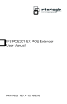
Corporate Headquarters GarrettCom, Inc. Magnum P80F & P80C Personal Switches 47823 Westinghouse Dr. Fremont, CA 94539 Phone (510) 438-9071 Fax (510) 438-9072 Website: http://www.GarrettCom.com email [email protected] Installation and User Guide www . GarrettCom . com www . GarrettCom . com $5.00 USD Magnum P80F & P80C Personal Switches Installation and User Guide (07/03) Magnum™ P80F & P80C Personal Switches Installation and User Guide Part #: 84-00079, (Rev B 4/01) Trademarks Ethernet is a trademark of Xerox Corporation NEBS is a trademark of Telcordia Technologies UL is a registered trademark of Underwriters Laboratories GarrettCom, Magnum and Personal Switch are trademarks and Personal Switch is a registered trademark of GarrettCom, Inc. Important: The Magnum P80F & P80C Personal Switch contains no user serviceable parts. Attempted service by unauthorized personnel shall render all warranties null and void. If problems are experienced with Magnum P80F & P80C Personal Switch products, consult Section 5, Troubleshooting, of this User Guide. Copyright © 2001 GarrettCom, Inc. All rights reserved. No part of this publication may be reproduced without prior written permission from GarrettCom, Inc. Printed in the United States of America. www . GarrettCom . com i Magnum P80F & P80C Personal Switches Installation and User Guide (07/03) Contacting GarrettCom, Inc Please use the mailing address, phone and fax numbers and email address listed below: GarrettCom, Inc. 47823 Westinghouse Dr. Fremont, CA 94539 Phone (510) 438-9071 Fax (510) 438-9072 Website: http://www.GarrettCom.com email [email protected] Federal Communications Commission Radio Frequency Interference Statement This equipment generates, uses and can radiate frequency energy and if not installed and used properly, that is in strict accordance with the manufacturer's instructions, may cause interference to radio communication. It has been tested and found to comply with the limits for a Class A computing device in accordance with the specifications in Subpart J of Part 15 of FCC rules, which are designed to provide reasonable protection against such interference when operated in a commercial environment. Operation of this equipment in a residential area is likely to cause interference, in which case the user at his own expense will be required to take whatever measures may be required to correct the interference. www . GarrettCom . com ii Magnum P80F & P80C Personal Switches Installation and User Guide (07/03) The Magnum Line ETHERNET CONNECTIVITY PRODUCTS "DESIGNED AND MANUFACTURED IN THE USA" OVERVIEW GarrettCom, Inc.offers the premium-quality Magnum™ line of Ethernet LAN connectivity products with industry-standard functionality and built-in fiber configurability. Magnum products are designed for use in demanding Carrier Class, Industrial Grade and OEM applications where reliability is a primary consideration. 4K-Series Switches, 100 & 10Mbps, copper ports with optional fiber port, with auto-negotiating full switching performance Quad-Series Fiber Switches, 100 & 10Mbps, fiber and copper ports, mixed-speed and mixed-media types, full switching performance “Outdoor” Ethernet Switch, for temperature uncontrolled locations 6 10/100 and 2 100Mb fiber ports, can be connected in strings Mixed-Media Fiber Hub, 16-port Stackable, 10/100 auto-sensing Dual Speed 8-port and 16-port Stackables, 10/100 auto-sensing Stackable Hubs, SNMP Optional 10Mb series and 100Mb series, both w/ optional port modules Personal Switches, 10/100Mb 8 port dual speed, Auto-negotiable with fiber option Personal Hubs, 100Mb or 10/100Mb 8-port, with two switched ports (1 fiber built in) Personal Hubs, 10Mb series 8-port + AUI, stackable to 5 high, + optional BNC of fiber port 8 or 9-port and 4 or 5-Port Personal Hubs, w/ man. up-link sw. Media Converters, 10Mb and 100Mb series All media combinations, incl. fiber ST, SC, mm., single mode The “X-line” of configurable MiXed Media products: Stackable Concentrators, SNMP optional, 13-Ports Mini-Concentrators, 7 Ports, Repeaters, 2-Ports Repeater Port Modules (RPMs), 6 types for Ethernet media Bridge Port Modules (BPMs), 4 types, for segment isolation Fan-Outs, 10Mb series 2, 4 and 8 Port Models Transceivers, 10Mb and 100Mb series 10Mb Mini-Transceivers and Coax Models, All Types - Apr, 01 www . GarrettCom . com iii Magnum P80F & P80C Personal Switches Installation and User Guide (07/03) TABLE OF CONTENTS PAGE 1.0 SPECIFICATIONS ........................................................................................2 1.1 Technical Specifications..................................................................................... 2 1.2 Ordering Information.......................................................................................... 4 2.0 INTRODUCTION..........................................................................................5 2.1 Inspecting the Package and Product ................................................................... 5 2.2 Product Description ............................................................................................ 5 2.2.1 Magnum P80F Chassis............................................................................ 6 2.2.2 Magnum P80C Chassis ........................................................................... 7 2.3 Up-link on Port # 1SW for Cascading .............................................................. 7 2.4 100Mbps Fiber port, ST or SC Connector for P80F .......................................... 8 2.5 Frame buffering and Latency............................................................................. 9 2.6 Features and Benefits.........................................................................................10 2.7 Applications (P80F & P80C) .............................................................................11 3.0 INSTALLATION.........................................................................................14 3.1 Locating Magnum P80F & P80C Personal Switches.........................................14 3.1.1 Table-Top or Shelf Mounting ................................................................14 3.1.2 Wall (or Vertical Surface) Mounting .....................................................14 3.2 Connecting Ethernet Media .............................................................................15 3.2.1 Connecting Twisted Pair (RJ-45, Cat-3, CAT-5)...................................15 3.2.2 Connecting Fiber Optic SC-type, “Twist-lock” .....................................16 3.2.3 Connecting Fiber Optic ST-Type, “Snap-In”.........................................16 3.2.4 Connecting Fiber Optic Single-mode.....................................................16 3.2.5 Power budget Calculation for P80F Fiber media ...................................17 3.2.6 Connecting to NICs which support Auto-Negotiation ...........................17 3.3 Powering the Magnum P80F & P80C ..............................................................18 4.0 OPERATION ...............................................................................................19 4.1 Dual-Speed Functionality and Switching ..........................................................19 4.2 Auto-negotiation and speed-sensing .................................................................20 4.3 Full or Half duplex, manual selection for P80F Models ....................................20 4.4 Full or Half duplex, manual selection for P80C ................................................20 4.5 LEDs .................................................................................................................21 4.6 Up-link Port, 1SW or 1 .....................................................................................21 4.7 Use with media converters.................................................................................21 5.0 TROUBLESHOOTING ...............................................................................22 5.1 Before Calling for Assistance ............................................................................22 5.2 When Calling for Assistance .............................................................................23 5.3 Return Material Authorization (RMA) Procedure .............................................23 5.4 Shipping and Packaging Information.................................................................24 APPENDIX A: WARRANTY INFORMATION ...........................................................24 Revisions Rev B 04/01 : Change the company name to GarrettCom, Inc. (Formerly it was Garrett Communications). There are no changes to the content of the material at this time Rev A 09/00 : This revision is the initial release of the P80F &P80C Personal Switch user manual. www . GarrettCom . com 1 Magnum P80F & P80C Personal Switches 1.0 SPECIFICATIONS 1.1 Technical Specifications Installation and User Guide (07/03) Ports Performance When a port is operating at 100Mbps: Data Rate: 100Mbps When a port is operating at 10 Mbps: Data Rate: 10 Mbps Network Standards 100Mb: Ethernet IEEE 802.3u, 100BASE-TX, 100BASE-FX 10 Mb: Ethernet IEEE 802.3, 10BASE-T Auto-sensing for speed: IEEE 802.3u Packet-Processing Between Domains Filtering and Forwarding Rate from 100Mbps ports: 148,800 pps max Filtering and Forwarding Rate from 10 Mbps ports: 14,880 pps max. Processing type: Store and Forward Auto-learning: 16K address table, shared for all traffic domains Packet buffers: 512KB, dynamically shared on all domains Latency (not including packet time): 100 to 10 Mbps: 5µs 10 to 100Mbps: 5µs Path Delay Value: 50 BT on all ports Maximum Ethernet Segment (or Domain) Lengths 10BASE-T (Unshielded twisted pair) 100BASE-TX (CAT 5 UTP) - 100 m (328 ft) - 100 m (328 ft) 100BASE-FX, half-duplex: (multi-mode) 100BASE-FX, full-duplex: (multi-mode) 100BASE-FX, half-duplex: (single-mode) 100BASE-FX, full-duplex: (single-mode) 100BASE-FX, full-duplex: (single-mode, long) - 412 m (1350 ft) - 2.0 km (6,562 ft) - 412 m (1350 ft) - 20.0 km (65,620 ft) - 40.0 km (131,240 ft) Operating Environment Ambient Temperature: 32ºF to 120ºF (0ºC to 50ºC) Storage Temperature: -5ºC to 160ºF (-20ºC to 70ºC) Ambient Relative Humidity: 10% to 95% (non-condensing) Power Supply (External) Input: 95-125 vac at 60Hz for “-d” Models 200-250 vac at 50Hz for “-i” Models, which have IEC power cable connector in the external power unit. Output: 5VDC, 2Amps Polarity: center positive, shell negative Power Consumption: 8 watts typical, 10 watts max. www . GarrettCom . com 2 Magnum P80F & P80C Personal Switches Installation and User Guide (07/03) External -48VDC Power Supply (Optional) Power Input Voltage: 36 to 70 VDC (auto ranging), “-, GND, +” Power Consumption: 8 watts typical, 10 watts max. Network Cable Connectors - for eight RJ-45 shielded female ports and 1 fiber port 100Mbps: Category 5 UTP/STP, fiber (50/125, 62.5/125, 9/125 micron) 10 Mbps: Category 3, 4, 5 UTP (Note: auto-sensing does not sense cable type) Maximum Load per port: 60 mA Up-Link, Port # 1 or 1SW Port # 1 (switched RJ-45) has a manual crossover (MDIX up-link) switch for connection to a central switch or to another P80F, P80C (or equal) unit. The uplink port # 1 is auto-sensing for speed, and its auto-negotiating up-link feature works the same at 10 Mbps or 100Mbps speed and at full- or half-duplex mode. Full- or Half-Duplex selection on switched Ports # 2 or 2SW for Magnum P80F Manual switch selects fiber port for FDX or HDX. See Section 4.3 for details. Full-Fixed or Auto-negotiation selection on switched Ports # 2 or 2SW for Magnum P80 Manual switch selects port #2 for “FF” or “A”. See Section 4.3 for details. Packaging Enclosure: Rugged high-strength sheet metal. Metal mounting clips included. Suitable for wiring closet shelf, wall or desktop mounting. Dimensions: 1.25 in H x 6.75 in W x 5.0 in D (3.2 cm x 17.1 cm x 12.7 cm) Weight (of Switch unit): 1.0 lb. (455 g.) Weight (of power supply unit): 1.0 lb. (455 g.) Cooling method: Convection LED Indicators PWR: Steady On when power applied ERROR: Self-test at power up failed SPEED (with LINK ON): ON = 100Mbps; OFF = 10 Mbps LINK/ACT: Steady On for LINK with no traffic, blinking indicates port is transmitting / receiving. F/H: ON = full-duplex, OFF = half-duplex Agency Approvals UL Listed (UL 1950), cUL, CE Emissions: meets FCC Part 15, Class B Warranty: Three years, return to factory www . GarrettCom . com 3 Made in USA Magnum P80F & P80C Personal Switches 1.2 Installation and User Guide (07/03) Ordering Information Magnum P80F, 10/100 Personal Switch with a 100Mb Fiber Port Magnum P80F-MSC-d, or -i: 8-port Personal Switch with one 100Mbps switched fiber port (multi-mode SC-type connector), and seven “N-way” half- or full-duplex switched RJ-45 10/100 auto-negotiating ports. Includes store-and-forward switching that filters and forwards data moving between the ports. The internal switch has 16K nodes address table and 512KB packet buffers. External power supply. Magnum P80F-MST-d, or -i: Same as P80F but with multi-mode ST- type fiber connector. Magnum P80F-SSC-d, or -i: Same as P80F but with single-mode SC-type fiber connector. Magnum P80F-SSCL-d, or -i: Same as P80F but with single-mode (Long reach, 40Km) SC-type fiber connector. Magnum P80F-MTRJ-d, or -i: Same as P80F but with multi-mode MTRJtype fiber connector. Magnum P80C, 10/100 Personal Switch with all copper ports Magnum P80C-d, or -i: 8-port 10/100Mb “copper” office switch with eight 10/100 N-way auto-negotiating switched ports. Includes store-and-forward switching that filters and forwards data moving between the ports. The internal switch has 16K nodes address table and 512KB packet buffers. External power supply. Use “-d” suffix for external power supply at 115vac 60Hz; use “-i” suffix for external at 230vac 50Hz. GarrettCom reserves the right to change specifications, performance characteristics and / or model offerings without notice. www . GarrettCom . com 4 Magnum P80F & P80C Personal Switches Installation and User Guide (07/03) 2.0 INTRODUCTION 2.1 Inspecting the Package and Product Examine the shipping container for obvious damage prior to installing this product; notify the carrier of any damage that you believe occurred during shipment or delivery. Inspect the contents of this package for any signs of damage and ensure that the items listed below are included. This package should contain: 1 Magnum P80F Personal Switch with a Fiber Port, or Model P80C with all copper ports. 1 External Power Supply, 5VDC from either 115v 60Hz or 230v 50Hz 1 Set of metal clips and screws for secure shelf or wall-mounting 1 Installation and User Guide 1 Product Registration Card Remove the Magnum P80F or P80C Personal Switch from the shipping container. Be sure to keep the shipping container should you need to ship the unit at a later date. To validate the product warranty, please complete and return the enclosed Product Registration Card to GarrettCom as soon as possible. In the event there are items missing or damaged, contact your supplier. If you need to return the unit, use the original shipping container. Refer to Chapter 5, Troubleshooting, for specific return procedures. 2.2 Product Description - General The P80-series Personal Switches provide the performance of a built-in 100Mb switched fiber link upstream, coupled with the convenience of switched 10/100Mb copper ports for workplace LAN connections, all in one compact unit. Magnum P80F “Future-proof Fiber” models have been designed with one full-duplex 100Mbps switched fiber port, and seven of “N-way” switched RJ-45 with full / half-duplex 10/100 auto-negotiating RJ-45 ports. The P80C “Copper” model has been designed with all eight RJ-45 switched ports with “N-way” x half/full duplex capability and functions as 10/100 auto- www . GarrettCom . com 5 Magnum P80F & P80C Personal Switches Installation and User Guide (07/03) negotiating ports. For half- or full duplex selection on the P80F, and Full-fixed and Autonegotiation selection on the P80, see sections 4.3 and 4.4. The Magnum P80 & P80F Personal Switches provide the switching speed and the reliability to smoothly support multiple workgroups at 100Mbps or 10 Mbps speed. The optional fiber port is normally configured and tested with the Magnum P80F unit in the factory, and available in all popular fiber connectors. Designed for use in departments with multiple workgroups, in remote offices, lab, classroom and in network traffic centers, or multi-system power users, the Magnum P80 & P80F Personal Switches are easy to install and use. Addresses of attached nodes are automatically learned and maintained, adapting the switching services to network changes and expansions. Top-mounted LEDs provide status information on each port. The Magnum P80 & P80F Personal Switches provide high performance plug-and-play operation in compact packages. The P80 & P80F Personal switches are non-blocking on all ports and include 512KB packet buffers and 16K-node address table for advanced performance. The Magnum P80 & P80F Personal Switches, with store-and-forward switching, filter all faulty packets to minimize traffic congestion. 2.2.1 Magnum P80F chassis with fiber ST or SC (m.m. or single-mode) connector 5V, 2Amps Magnum P80 Personal Switch Link/Act Speed F/H Power Error GARRET PORTS Tx 1 UPLINK UPLINK Rx = F Fiber ST above 2 3 2 1SW 4 3 5 4 6 5 7 6 8 7 8 X H 2SW 5V, 2Amps Magnum P80 Personal Switch Link/Act Speed F/H Power Error GARRET PORTS Tx F Rx 1 UPLINK H = F 1SW 2 2 3 4 3 5 4 6 5 7 6 8 7 8 X H 2SW Fiber SC above The Magnum P80F chassis houses one main PC board. The power supply unit is external. The front side of the chassis has eight RJ-45 twisted-pair ports and one 100Mbps fiber www . GarrettCom . com 6 Magnum P80F & P80C Personal Switches Installation and User Guide (07/03) port. Port # 2SW always supports fiber ports only and the RJ-45 connector is inoperative at all times. LEDs to indicate operating status of all ports are mounted on the top. There are power (PWR) and ERROR (self-test at power up failed) indicators for the unit. For each port, there are Link and Activity (LINK/ACT) LEDs indicating traffic, and speed (ON for 100Mbps), and full/half (F/H) duplex indicators. The DC power plug connector or “jack” is in the left rear of the chassis. The external power supply is 5VDC at either 95 - 125vac at 60 Hz for “-d” models or 120-230vac at 50Hz for “-i” models that have IEC power cable connector in the external power supply housing. 2.2.2 Magnum P80C chassis with all RJ-45 Copper ports The Magnum P80C chassis houses one main PC board. The power supply unit is external. The front side of the chassis has eight twisted-pair switched ports. Port 2SW has manually-selectable Full-Fixed and Auto-negotiation capability. See section 4.4. 5VDC, Magnum P80 Personal Link/Act Speed F/ Powe Erro GARRET Tx PORTS 1 UPLINK UPLINK 2 3 3 1SW 4 5 4 6 5 7 6 7 = FF A 2SW LEDs to indicate operating status of all ports are mounted on the top. There are power (PWR) and ERROR (self-test at power up failed) indicators for the unit. For each port, there are Link and Activity (LINK/ACT) LEDs indicating traffic, speed (ON for 100Mbps), and full/half duplex (F/H is ON for full duplex) indicators. The DC power plug connector or “jack” is in the left rear of the chassis, like the P80F. The external 5VDC power supply is for either 95 - 125vac at 60 Hz for “-d” models or 120-230vac at 50Hz for “-i” models that have IEC power cable connector in the external power supply housing 2.3 Up-link Port 1SW for Cascading The unit has an up-link Port # 1 or 1SW, located on the left-front side of the Switch. It enables the port’s twisted pair cable to cascade to another shared hub or switching hub port. (See Section 4.6 for more details about up-link). Port #1SW is capable of full- and half-duplex mode auto-sensing, based on the capability of the connected device. The up-link feature operates the same, whether Port # 1SW is connected to either 100Mbps or 10Mbps devices. www . GarrettCom . com 7 Magnum P80F & P80C Personal Switches Installation and User Guide (07/03) When the up-link port is used to cascade two P80-series Personal Switches, the auto-sensing feature will cause the connecting link to operate at 100Mbps speed and full-duplex mode. 2.4 Fiber port, ST or SC Connector for Model P80F Tx Rx UPLINK = F Tx Rx F H UPLINK X = H F X H 100Mbps Fiber port, ST-type mm or SC type (single-mode or multi-mode) The Fast Ethernet fiber switched port on the Magnum P80F is set to operate at fixed 100Mb speed for guaranteed high performance. The P80F’s fiber port is factory-built as either a multi-mode ST, multi-mode SC, multi-mode MTRJ or single-mode or long-reach SC connector. The 100Mb fiber port will run at 100Mbs speed at all times with manually selected full- and half-duplex capability. The 100Mbps fiber port is a switched port and performs as a domain, providing a high bandwidth backbone connection (no media converter is required!) and supporting long (up to 40km) fiber cable distances for installation versatility. Ports 2SW (the fiber port) has an “F - H” user-selectable manual switch. When set in the “F” position, it forces full-duplex mode. When set in the “H” position, it forces half-duplex mode, still at 100Mbps speed. On Magnum P80F units, there are three LED’s for the switched ports. One (LK/ACT) is steady ON to indicate LINK, blinking indicates the port is transmitting and receiving. The SPEED LED is ON for 100Mbps and OFF for 10 Mbps (when LINK is made). The F/H indicates full-duplex when ON, when it is OFF, operation is half-duplex. A fiber cable must be connected to the 100Mb port and a proper link (LK lit) must be made with the device at the other end of the cable in order for these LEDs to provide valid indications of operating conditions. www . GarrettCom . com 8 Magnum P80F & P80C Personal Switches 2.5 Installation and User Guide (07/03) Frame Buffering and Latency The Magnum P80 & P80F are store-and-forward switches. Each frame (or packet) is loaded into the Switch’s memory and inspected before forwarding can occur. This technique ensures that all forwarded frames are of a valid length and have the correct CRC, i.e., are good packets. This eliminates the propagation of bad packets, enabling all of the available bandwidth to be used for valid information. While other switching technologies such as "cut-through" or "express" impose minimal frame latency, they will also permit bad frames to propagate out to the Ethernet segments connected. The "cut-through" technique permits collision fragment frames, which are a result of late collisions, to be forwarded to add to the network traffic. Since there is no way to filter frames with a bad CRC (the entire frame must be present in order for CRC to be calculated), the result of indiscriminate cut-through forwarding is greater traffic congestion, especially at peak activity. Since collisions and bad packets are more likely when traffic is heavy, the result of store-and-forward operation is that more bandwidth is available for good packets when the traffic load is greatest. To minimize the possibility of dropping frames on congested ports, each Magnum P80 & P80F Personal Switches dynamically allocates buffer space from an 1MB memory pool, ensuring that heavily used ports receive very large buffer space for packet storage. (Many other switches have their packet buffer storage space divided evenly across all ports, resulting in a small, fixed number of packets to be stored per port. When the port buffer fills up, dropped packets result.) This dynamic buffer allocation provides the capability for the maximum resources of the Magnum P80 unit to be applied to all traffic loads, even when the traffic activity is unbalanced across the ports. Since the traffic on an operating network is constantly varying in packet density per port and in aggregate density, the Magnum P80 & P80F Personal Switches are constantly adapting internally to provide maximum network performance with the least dropped packets. When the Switch detects that its free buffer queue space is low, the Switch sends industry standard (full-duplex only) PAUSE packets out to the devices sending packets to cause “flow control”. This tells the sending devices to temporarily stop sending traffic, which allows a traffic catch-up to occur without dropping packets. Then, normal packet buffering and www . GarrettCom . com 9 Magnum P80F & P80C Personal Switches Installation and User Guide (07/03) processing resumes. This flow-control sequence occurs in a small fraction of a second and is transparent to an observer. See Section 4.6 for additional details. Another feature implemented in Magnum P80 & P80F Personal Switches is a collision-based flow-control mechanism (when operating at half-duplex only). When the Switch detects that its free buffer queue space is low, the Switch prevents more frames from entering by forcing a collision signal on all receiving half-duplex ports in order to stop incoming traffic. The latency (the time the frame spends in the Switch before it is sent along or forwarded to its destination) of the P80 & P80F Personal Switches varies with the port-speed types, and the length of the frame is a variable here as it is with all store-and-forward switches. For 10 Mb-to-10 Mb or 10 Mb-to-100Mb or 100Mb-to-10 Mb forwarding, the latency is 15 microseconds plus the packet time at 10 Mb. For 100Mb-to-100Mb forwarding, the latency is 5 microseconds plus the packet time at 100Mb. 2.6 Features and Benefits 100Mb switching services for high performance Ethernet LANs Magnum P80 & P80F Switches provide Fast Ethernet switching on all ports. They perform high speed filter/forward operations on the traffic, giving each port’s segment a full 100Mb (or 10 Mb) of bandwidth. Option for one “future-proof” fiber ports connector, Model P80F Built-in fiber ports may be ordered with 100Mb full-duplex mm ST, SC, MTRJ and single-mode SC, SSCL-type connectors. The fiber port can be set as full or half-duplex mode by a manual switch selection. No Media Converter needed. Model P80C with all RJ-45 (copper) ports RJ-45 ports provide twisted pair segment connections, with N-way autonegotiation to all the ports. All RJ-45 ports are capable of half- or full-duplex. Top-mounted LEDs for convenient viewing The LEDs that indicate operating status are on the top of the unit for easy viewing in any situation. For the difficult near-the-floor mounting locations that are convenient for keeping the cables out of the way, the LEDs are still easily viewed. www . GarrettCom . com 10 Magnum P80F & P80C Personal Switches Installation and User Guide (07/03) Up-Link on port # 1 for a high speed “copper” connection An up-link switch is built in for port # 1. The F/H 10/100 switched RJ-45 port # 1 can support a local server, a power user, another hub or switch cascaded, or a switched “stack” connection to another P80F or P80C for expansion. Installation is “Plug and Play”, operation is transparent to software The Magnum P80F & P80C operates as a hardware switch, only forwarding those packets from each domain that are needed on the other domains. Internal address tables are self-learning, enabling users to change port connections or 10/100 domains without affecting operations. Small enclosure enables use in offices, labs and classrooms The compact packaging of Magnum P80F & P80C’s allows them to be installed in offices and labs, or virtually any workspace location within reach of a standard AC wall outlet. They come in a durable metal enclosure for table-top or wallmount. There is a choice of external power supplies, for either 115vac or 230vac. 2.7 Applications The P80F & P80C are designed to bring future-proof fiber connectivity and widely- used copper connectivity to small user groups in offices, classrooms and labs. Example 1. Magnum P80F In this example, a Magnum P80F Personal Switch serves a small class or lab with multi-servers and mixed-speed requirements like surfing the Internet or downloading data from servers or other sources. Some users operate at 100Mbps, and some users and utility devices (such as print servers) run at 10 Mbps. High performance users need a high bandwidth backbone for access to a central LAN and central file servers. A Magnum P80F Personal Switch serves this requirement economically. The eight full-and half duplex switched ports capability makes the required setup simple. Any attached node can change speed at any time without affecting network operation or impacting other users. www . GarrettCom . com 11 Magnum P80F & P80C Personal Switches Installation and User Guide (07/03) 5V, 2Amps Magnum P80 Personal Switch Link/Act Speed F/H Power Error GARRET PORTS Tx Rx 1 UPLINK UPLINK = F 100Mbps fiber 1SW 2 2 3 4 3 5 4 6 5 7 6 8 7 8 X H 2SW Print Server 1 2 3 4 100 5 6 1 2 3 4 5 6 100 Server 100 100 100 10 10 Mbps 10 Mbps Figure 2.7.1: A P80F connects combinations of 10 Mbps and100Mbps network devices and provides a Fast Ethernet fiber backbone for access to the central LAN. Where there is existing 10 Mbps hubs or switches users, they can easily be cascaded into any port of the P80F. This allows a simple plug-and-play addition of 100Mbps ports to an existing 10 Mbps network without having to change it. Nodes that are capable of 100Mbps speed can be moved to a P80F port, and will automatically operate at the higher speed. The 100Mb fiber port on the P80F can be used for accommodating high performance data transfers, and provides fiber connectivity built-in rather than needing an auxiliary media converter unit. The 100Mbps traffic does not use the bandwidth of the 10 Mbps domain, so overall performance of the network is sustained at the highest possible level. Example 2. Magnum P80C The Magnum P80C fits very well in a small business experiencing a need to scale its LAN quickly and cost effectively. With its Half / Full duplex switching capability, the P80C provides a very economical high bandwidth solution at each copper port. The Dual-Speed functions support a mixed environment of 10 Mbps and 100Mbps users, and the switching full / half duplex capability on all eight ports provides bandwidth for high performance. The up-link on Port 1 enables easy expansion. www . GarrettCom . com 12 Magnum P80F & P80C Personal Switches Installation and User Guide (07/03) 5VDC, Magnum P80 Personal Link/Act Speed F/ Powe Erro GARRET Tx Rx PORTS 1 UPLINK UPLINK 2 3 3 1SW 4 5 4 6 5 7 6 7 = FF A 2SW 12V, 1.5Amps Magnum DS80C Dual Personal Hub Powe Erro Link/Ac Spee PORTS 1SW F/ GARRETT Tx Rx UPLINK UPLINK = F X 2SW 3 2 4 3 1S 1 H 3 4 5 6 4 5 5 7 6 8 7 8 6 Print Server 2S Router 10 Serve 10 10 1 10 1 Users 100Mb Servers and Workstations Figure 2.7.2: Two P80C connects together to provide 10 Mbps and100Mbps network with Fast Ethernet backbone. In this example, two of the Magnum P80C Personal Switch cascaded together to serve a small office with multi-servers, print server, internet access and mixed-speed requirements. The users operate at 100Mb as well as at 10 Mb, and utility devices (such as print servers) run at 10 Mbps. High performance users need a high bandwidth up-link for access to a central LAN and central file servers. Any attached node can change speed at any time without affecting network operation or impacting other users. www . GarrettCom . com 13 Magnum P80F & P80C Personal Switches 3.0 Installation and User Guide (07/03) INSTALLATION This chapter provides instructions for installing Magnum P80-series units. 3.1 Locating Magnum P80F & P80C 10/00Mb Personal Switch The location of a Magnum P80F & P80C Personal Switch is dependent on the physical layout of the network. Typically the switch is located in a workplace site. The compact size of the unit allows it to be conveniently placed in an office, classroom or lab area, and it can also be either shelf- of wall-mounted (see mounting instructions in 3.1.2 below). Metal wallmounting clips are included with the unit. Locate an AC receptacle that is within six feet (2 meters) of the intended Magnum P80F & P80C site. The rugged metal case of the Magnum P80F & P80C will normally protect it from accidental damage in a lab or workplace setting. Maintain an open view of the top surface to visually monitor the status LEDs. 3.1.1 Table-Top or Shelf Mounting The Magnum P80F & P80C Personal switch can be easily mounted on a table-top or any suitable horizontal surface, and has four rubber feet to provide stability without scratching finished surfaces. 3.1.2 Wall (or vertical surface) mounting Each Magnum P80-series Personal Switch is shipped with two metal mounting brackets (and screws) to allow the Proper attachment of mounting bracket for wall mounting unit to be mounted in nearly any desired orientation or position. The brackets are attached to the metal Switch case using one of the 5VDC, Magnum P80 Personal Switch Power Error GARRETT Speed Link/Act F/H PORTS 1SW 2SW 3 4 5 6 7 Top view- Magnum P80F with brackets attached for wall www . GarrettCom . com 14 Magnum P80F & P80C Personal Switches Installation and User Guide (07/03) metal screws for each bracket and attaching to the Magnum P80F and P80C through the round hole of the bracket. A user-supplied screw attaches the bracket to the mounting surface. It is recommended to use appropriate # 4 screws for attaching mounting bracket to wall (e.g wood screw, self-tapping screw, machine screw). It is also recommended that the brackets be attached to two opposite corners of the unit. When properly attached, the brackets will extend slightly below the base of the unit to allow clearance for the rubber feet. 3.2 Connecting Ethernet Media The Magnum P80C Personal Switch can be connected to two media types i.e. 100BASE-TX and 10BASE-T, however, P80F can be connected to the following three media types: 100BASE-TX, 10BASE-T and 100BASE-FX. CAT 5 cables should be used when making 100BASE-TX connections. When the ports are used as 10BASE-T ports, CAT 3 may be used. In either case, the maximum distance for unshielded twisted pair cabling is 100 meters (328 ft). For fiber port 100BASE-FX multi-mode, 50/125 or 62.5/125 microns cabling can be used, whereas for single-mode, 9/125 microns cabling should be used. Fiber cabling supports much longer cable distance and higher bandwidths as compared to copper wiring. Media IEEE Standard Connector Twisted Pair (CAT 3 or 5) 10BASE-T RJ-45 Twisted Pair (CAT 5) 100BASE-TX RJ-45 Fiber (Multi-mode) 100BASE-FX ST Fiber (Multi-mode) 100BASE-FX SC Fiber (Single-mode) 100BASE-FX SC Fiber (Multi-mode) 100BASE-FX MTRJ NOTE : It is recommended that high quality CAT. 5 cables (which work for both 10 Mbps and 100Mbps) be used whenever possible in order to provide flexibility in a mixed-speed network, since P80-series switch ports are auto-sensing for either 10 and 100Mbps. Note that the auto-sensing function does not sense the cable type. 3.2.1 Connecting Twisted Pair (RJ-45, CAT 3 or CAT 5, Unshielded or Shielded) The following procedure describes how to connect a 10BASE-T or 100BASE-TX twisted pair segment to the RJ-45 port. The procedure is the same for both unshielded and shielded twisted pair cables. www . GarrettCom . com 15 Magnum P80F & P80C Personal Switches 1. 2. 3. 4. Installation and User Guide (07/03) Using standard twisted pair media, insert either end of the cable with a RJ-45 plug into the RJ-45 connector of the port. Note that, even though the connector is shielded, either unshielded or shielded cables and wiring may be used. Connect the other end of the cable to the corresponding device. Use the LINK LED to ensure proper connectivity by noting that the LED will be illuminated when the unit is powered and proper connection is established. If this does not help, ensure that the cable is connected properly and that the device on the other end is powered and is not defective. For Port # 1 or 1SW, if the LINK LED is not illuminated, move the switch which has a cross-over or up-link for linking to another hub or Switch. 3.2.2 Connecting Fiber Optic ST-type, “twist-lock” The following procedure applies to installations using ST-type fiber connectors. This procedure applies to ports using multi-mode ST fiber connectors. 1. Before connecting the fiber optic cable, remove the protective dust caps from the tips of the fiber connectors. Save these dust caps for future use. 2. Wipe clean the ends of the dual connectors with a soft cloth or lint-free lens tissue dampened in alcohol. Make certain the connectors are clean before connecting. Note: One strand of the duplex fiber optic cable is coded using color bands at regular intervals; you must use the color-coded strand on the associated ports at each end of the fiber optic segment. 3. Connect the Transmit (TX) port (light colored post) on the Magnum Fiber port to the Receive (RX) port of the remote device. Begin with the color-coded strand of the cable for this first TX-to-RX connection. 4. Connect the Receive (RX) port (dark colored post) to the Transmit (TX) port of the remote device. Use the non-color coded fiber strand for this. 5. The LINK LED on the front of the fiber connector will illuminate when a proper connection has been established at both ends (and when power is ON in the unit). If LINK is not lit after cable connection, the normal cause is improper cable polarity. Swap the fiber cables at the fiber connector to remedy this situation. 3.2.3 Connecting Fiber Optic SC-type, "Snap-In" The following procedure applies to installations using SC-type fiber connectors, i.e., using multi-mode SC and SC single-mode. When connecting fiber media to SC connectors, simply snap on the two square male connectors into the SC female jacks of the Fiber connector until it clicks and secures. 3.2.4 Connecting Single-Mode Fiber Optic When using single-mode fiber cable, be sure to use single-mode fiber port connectors. Single-mode fiber cable has a smaller diameter than multi-mode fiber cable (9/125 microns for single-mode, 50/125 or 62.5/125 microns for multi-mode where xx/xx are the diameters of the core and the core plus the cladding respectively). Single-mode fiber allows full bandwidth at longer distances, about 20Km with the multi-mode SC. www . GarrettCom . com 16 Magnum P80F & P80C Personal Switches Installation and User Guide (07/03) The same procedures as for multi-mode fiber apply to single-mode fiber connectors. Follow the steps listed in Section 3.2.2 above. 3.2.5 Power Budget Calculations for P80F Fiber Media Receiver Sensitivity and Transmitter Power are the parameters necessary to compute the power budget. To calculate the power budget of different fiber media installations using Magnum products, the following equations should be used: OPB (Optical Power Budget) = PT(min) - PR(min) where PT = Transmitter Output Power, and PR = Receiver Sensitivity Worst case OPB = OPB - 1dB(for LED aging) - 1dB(for insertion loss) Worst case distance = {Worst case OPB, in dB} / [Cable Loss, in dB/Km] where the “Cable Loss” for 62.5/125 and 50/125µm (m.m.) is 2.8 dB/km, and the “Cable Loss” for 100/140 (Multi-mode) is 3.3 dB/km, and the “Cable Loss” for 9/125 (Single-mode) is 0.5 dB/km The following data has been collected from component manufacturer’s (HP’s and Siemens’) web sites and catalogs to provide guidance to network designers and installers. Fiber Port Module Speed, Std. Mode Std. km Wave- Cable X’mitr R’cvr Worst Worst* fdx length Size Output Sens. OPB, distance (hdx) nm PT , dB PR ,dB dB Km, fdx µm typical typical* OPB, distance dB Km, fdx P80F100Mb Multimode MST, MSC FX 100Mb SingleP80F-SSC mode FX 2 (0.4) 1300 62.5/125 -20 50/125 -23.5 -31 -31 9.0 5.5 2.5 2.0 14 12 5 4 20 (0.4) 1300 -31 14 28 17.5 35 P80F-MTRJ 100Mb Multimode FX 2 (0.4) 1300 62.5/125 -20 50/125 -23.5 -31 -31 9.0 5.5 3.0 2.0 15.8 12.2 5.5 4.0 100Mb Singlemode FX 40 (0.4) 1300 9/125 -34 27 54 32.5 65 Long Reach 9/125 -15 -5 * Note: The use of either multi-mode or single-mode fiber to operate at 100Mbps speed over long distances (i.e., over approx. 400 meters) can be achieved only if the following factors are both applied: • The 100Mb fiber segment must operate in full-duplex (FDX) mode, and • The worst-case OPB of the fiber link must be greater than the fiber cable’s passive Attenuation. (Attenuation = Cable loss + LED aging loss + Insertion loss + safety factor) 3.2.6 Connections to NICs which support Auto-Negotiation, RJ-45 ports The copper ports of Magnum P80F and P80C Personal Switches will function properly with NICs (Network Interface Cards) which support Auto-Negotiation, and the Fast Link Pulse www . GarrettCom . com 17 Magnum P80F & P80C Personal Switches Installation and User Guide (07/03) (FLP) coding for the 100BASE-TX signaling system. When connecting a NIC to the P80F or P80C, it may be necessary to reload the NIC drivers on the user device if the NIC has been communicating with a protocol other than 100BASE-TX (such as 10BASE-T). When 100Mb operation is agreed and in use, the SPEED LED is illuminated steady ON. It is OFF if there is no traffic or if 10 Mbps traffic. 3.3 Powering the Magnum P80F and P80C Each Magnum P80F and P80C Personal Switch is provided with an external power supply, and has a jack for the DC power cord in the rear. A lightweight DC power cord for 5V, 2.0 amps is supplied with each unit. The small DC power cord from the power supply plugs into the matching rear power jack of the P80F and P80C Personal switchess. When the power is applied, the green PWR LED will illuminate. Each Magnum P80F and P80C power supply supports standard AC installation environments and comes in two types; one version for AC input power of 115vac at 60Hz for “d ” models, and other version of 230vac at 50 Hz for “-i ” models that have IEC power cable connector in the external power unit. Examine the power supply to make sure the version you have is the right type for your AC power system. The 115vac version has a small transformer integral with a convenience power outlet plug, and a lightweight DC power cord to the applicable power jack on the Switch. The 230vac version has a small transformer integral with an IEC-type power plug for a usersupplied AC power cord with a convenience power outlet plug. www . GarrettCom . com 18 Magnum P80F & P80C Personal Switches Installation and User Guide (07/03) 4.0 OPERATION - the function and operation of the Magnum P80F and P80C switches. 4.1 Dual-Speed Functionality, and Switching The Magnum P80F and P80C Personal Switches provide eight switched ports, one of which may be 100Mb fiber on Model P80F. The architecture supports a dual speed switching environment, with a built-in full-duplex “future-proof” fiber port on the Model P80F. The Model P80C has RJ-45 copper on all the ports with auto-negotiation capability. The switched RJ-45 ports are full-duplex and auto-sensing for speed. (See section 2.2). When the connected device is 10 Mbps, the P80F obeys all the rules of 10 Mbps Ethernet configurations. The 10 Mbps users share a 10 Mbps traffic domain, and can “communicate with” 100Mbps users as well as 100Mbps domain. Similarly, the 100Mbps traffic obeys the rules of 100Mbps Ethernet, and can communicate with 10 Mb domain too. Magnum P80F and P80C units are plug-and-play devices. There is no software configuring to be done at installation or for maintenance. The only hardware configuration settings are user options for UP-LINK on RJ-45 port # 1. Half / Full duplex mode selection for the switched fiber port and FF/AN can be done through a switch accessed from the front of the unit for P80F and P80C. The internal functions of both are described below. Switching, Filtering and Forwarding Each time a packet arrives on one of the switched ports, the decision is taken to either filter or to forward the packet. Packets whose source and destination addresses on the same port segment will be filtered, constraining them to one port and relieving the rest of the network from processing them. A packet whose destination address is on another port segment will be forwarded to the appropriate port, and will not be sent to the other ports where it is not needed. Packets needed for maintaining the operation of the network (such as occasional multi-cast packets) are forwarded to all ports. The Magnum P80F and DP80C Personal Switches operate in the store-and-forward switching mode, which eliminates bad packets and enables peak performance to be achieved when there is heavy traffic on the network. Switching, Address Learning The Magnum P80F and P80C units have address table capacity of 16K node addresses, and are suitable for use in large networks. They are self-learning, so that as nodes are added or www . GarrettCom . com 19 Magnum P80F & P80C Personal Switches Installation and User Guide (07/03) removed or moved from one segment to another, the P80F and P80C automatically keeps up with node locations. An address-aging algorithm causes least-used addresses to fall out in favor of new frequently-used addresses. To reset the address buffer, cycle power down-and-up. 4.2 Auto-negotiation and Speed-sensing All eight RJ-45 ports independently support auto-negotiation for speed in 10BASE-T and 100BASE-TX modes. Operation is according to the IEEE 802.3u standard. When a RJ-45 cable connection is made, and each time a LINK is enabled, autonegotiation takes place. The P80F or P80C advertises its capability for 10 or 100 Mbps speed, and the device at the other end of the cable should similarly advertise / respond and both sides will agree to the speed being used. Depending upon the device connected, this will result in agreement to operate at either 10 Mbps or 100Mbps speed. When the ‘LINK/ACT’ LED is ON, steady ON indicates LINK with no traffic, blinking ON indicates the port is transmitting / receiving. The port has auto-negotiated for operation. (If a P80F or P80C RJ-45port is connected to a non-negotiating device, it will default to 10 Mbps speed and half-duplex mode, per the IEEE 802.3u standard). 4.3 FULL or HALF Duplex, manual selection for P80F Models Port # 2 or 2SW (the fiber port) has a “F - H” manual switch mounted on the front-left of the P80F personal Switch. While in the “F” position for fiber, it forces full-duplex mode at 100Mbps. In the “H” position, it forces half-duplex mode. (Note: While fiber port is used, the copper port # 2 will be automatically disabled.) 4.4 FULL or HALF Duplex, manual selection for P80C Models Ports # 2 have “FF - A” manual switch mounted on the front-left of the P80C Personal Switch. While in the “FF” position, it causes 100Mbps fixed full duplex only, which can be useful for using Fast Ethernet media converter (like Magnum 15E). While in “A” position, both N-way switch port # 2 support auto-negotiation and fullduplex mode is advertised for the standard 802.3u auto-negotiation session on RJ-45 switched ports. www . GarrettCom . com 20 Magnum P80F & P80C Personal Switches Installation and User Guide (07/03) 4.5 LED’s PWR: Illuminates GREEN, steady on when power applied. ERROR: Indicates the self-test at power up was not successful SPEED: Per port, ON = 100Mbps; OFF = 10 Mbps (when LINK is made) LINK/ACT: Per port, steady ON for LINK with no traffic, blinking indicates port is transmitting and receiving. F/H: ON = Full-Duplex and Link, OFF = Half-Duplex and / or no Link. 4.6 Up-link Port # 1 or 1SW Magnum P80F and P80Cs have one manual crossover (MDIX up-link) switch, port 1SW, on the front of the Personal Switch. This port can operate either Full/Half duplex mode. The up-link (or cross-over) on the # 1 or 1SW port allows its RJ-45 cable to connect for cascading to another hub or switch port. This allows repeater-to-repeater connections without a special cross-over cable. Port 1 works the same as regular ports for 10 Mbps or 100Mbps speed auto-sensing connections. Cascaded connections may be operated at either 10 or 100Mbps speed. The P80F even supports cascaded connections of both 10 Mbps and 100Mbps at the same time on different ports. When attaching a 10 Mbps hub or switch, the Ethernet configuration rules (hop count limits, etc.) for 10 Mbps domains are in effect. When the cascaded connection is operated at 100Mbps speed, because of its full duplex and switched port capability, does not need any PDV calculation for distances. Two P80F and P80Cs cascaded using RJ-45 ports will auto-negotiate to operate the connection at 100Mb/s. 4.7 Use with Media Converters Where an additional fiber connection (beyond the built-in fiber port as on P80F) may be desired, a media converter may be used. For P80F, the first two switched ports can be set to FDX manually, making typical 100Mb media converters (which can be troublesome with auto-negotiating ports, defaulting to 100Mb half-duplex) usable in either HDX or FDX mode as set by the user. Whereas for P80C the switched port 2 at “F” position supports 100Mbps Full duplex fixed only which is useful for the fast ethernet media converter (e.g. Magnum 15E). www . GarrettCom . com 21 Magnum P80F & P80C Personal Switches 5.0 Installation and User Guide (07/03) TROUBLESHOOTING All Magnum Ethernet products are designed to provide reliability and consistently high performance in all network environments. The installation of Magnum P80F & P80C Personal Switch is a straightforward procedure (see INSTALLATION, Section 3.0); the operation is also straightforward and is discussed in Section 4. Should problems develop during installation or operation, this section is intended to help locate, identify and correct these types of problems. Please follow the suggestions listed below prior to contacting your supplier. However, if you are unsure of the procedures described in this section or if the Magnum P80F & P80C Personal Switch is not performing as expected, do not attempt to repair the unit; instead contact your supplier for assistance or contact GarrettCom Customer Support. 5.1 Before Calling for Assistance 1. If difficulty is encountered when installing or operating the unit, refer back to the Installation Section of the applicable chapter of this manual. Also check to make sure that the various components of the network are interoperable. 2. Check the cables and connectors to ensure that they have been properly connected and the cables/wires have not been crimped or in some way impaired during installation. (About 90% of network downtime can be attributed to wiring and connector problems.) 3. Make sure that an AC power cord is properly attached to each Magnum P80F & P80C Personal Switch unit. Be certain that each AC power cord is plugged into a functioning electrical outlet. Use the PWR LEDs to verify each unit is receiving power. 4. If the problem is isolated to a network device other than the Magnum P80F & P80C Personal Switch product, it is recommended that the problem device is replaced with a known good device. Verify whether or not the problem is corrected. If not, go to Step 5 below. If the problem is corrected, the Magnum P80F & P80C Personal Switch and its associated cables are functioning properly. 5. If the problem continues after completing Step 4 above, contact your supplier of the Magnum P80F & P80C Personal Switch unit or if unknown, contact GarrettCom, Inc.by fax, phone or email ([email protected]) for assistance. www . GarrettCom . com 22 Magnum P80F & P80C Personal Switches 5.2 Installation and User Guide (07/03) When Calling for Assistance Please be prepared to provide the following information. 1. A complete description of the problem, including the following points: a. The nature and duration of the problem; b. Situations when the problem occurs; c. The components involved in the problem; d. Any particular application that, when used, appears to create the problem; 2. An accurate list of GarrettCom product model(s)involved, with serial number(s). Include the date(s) that you purchased the products from your supplier. 3. It is useful to include other network equipment models and related hardware, including personal computers, workstations, terminals and printers; plus, the various network media types being used. 4. A record of changes that have been made to your network configuration prior to the occurrence of the problem. Any changes to system administration procedures should all be noted in this record. 5.3 Return Material Authorization (RMA) Procedure All returns for repair must be accompanied by a Return Material Authorization (RMA) number. To obtain an RMA number, please use this URL https://rma.garrettcom.com/rma/rma_request_noaccount.php to fill out the form. Please have the following information readily available: Name and phone number of your contact person. Name of your company / institution Your shipping address Product name Serial Number (or Invoice Number) Packing List Number (or Sales Order Number) Date of installation Failure symptoms, including a full description of the problem. GarrettCom will carefully test and evaluate all returned products, will repair products that are under warranty at no charge, and will return the warranty-repaired units to the sender with shipping charges prepaid (see Warranty Information, Appendix A, for complete details). However, if the problem or condition causing the return cannot be duplicated by GarrettCom, the unit will be returned as: www . GarrettCom . com 23 Magnum P80F & P80C Personal Switches Installation and User Guide (07/03) No Problem Found. GarrettCom reserves the right to charge for the testing of non-defective units under warranty. Testing and repair of product that is not under warranty will result in a customer (user) charge. 5.4 Shipping and Packaging Information Should you need to ship the unit back to GarrettCom, please follow these instructions: 1. Package the unit carefully. It is recommended that you use the original container if available. Units should be wrapped in a "bubble-wrap" plastic sheet or bag for shipping protection. ( You may retain all connectors and this Installation Guide.) CAUTION: Do not pack the unit in Styrofoam "popcorn" type packing material. This material may cause electro-static shock damage to the unit. 2. Clearly mark the Return Material Authorization (RMA) number on the outside of the shipping container. 3. GarrettCom is not responsible for your return shipping charges. 4. Ship the package to: GarrettCom, Inc. 47823 Westinghouse Dr. Fremont, CA 94539 Attn.: Customer Service APPENDIX A: WARRANTY INFORMATION GarrettCom, Inc. warrants its products to be free from defects in materials and workmanship for a period of three (3) years from the date of shipment by GarrettCom. During this warranty period, GarrettCom will repair or, at its option, replace components in the products that prove to be defective at no charge other than shipping and handling, provided that the product is returned pre-paid to GarrettCom. This warranty will not be effective if, in the opinion of GarrettCom, the product has been damaged by misuse, misapplication, or as a result of service or modification other than by GarrettCom. GarrettCom reserves the right to make a charge for handling and inspecting any product returned for warranty repair which turns out not to be faulty. Please complete the warranty card as this acts as a product registration, and mail it to GarrettCom within two weeks of your purchase. www . GarrettCom . com 24