1
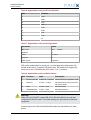
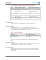
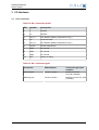
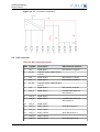
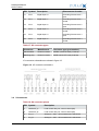
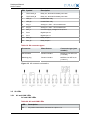
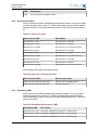
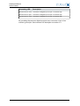
Arctic Control Hardware Manual
Arctic Control (2320, 2321)
Document Version 2.0
July 2014
Hardware Manual
Arctic Control
Copyright and Trademark
Copyright © 2008-2013, Viola Systems Ltd. All rights to this manual are owned
solely by Viola Systems Ltd. (referred elsewhere in this User’s Manual as
Viola Systems). All rights reserved. No part of this manual may be transmitted
or reproduced in any form or by any means without a prior written permission
from Viola Systems.
Viola Systems Ltd.
Lemminkäisenkatu 14-18 B
FI-20520 Turku
Finland
E-mail: [email protected]
Technical Support
Phone: +358 20 1226 226
Fax: +358 20 1226 220
E-mail: [email protected]
Internet: http://www.violasystems.com
2
Document Version 2.0
Hardware Manual
Arctic Control
Disclaimer
Viola Systems reserves the right to change the technical specifications
or functions of its products or to discontinue the manufacture of any of its
products or to discontinue the support of any of its products without any
written announcement and urges its customers to ensure that the information
at their disposal is valid.
Viola software and programs are delivered “as is”. The manufacturer does not
grant any kind of warranty including guarantees on suitability and applicability
to a certain application. Under no circumstance is the manufacturer or the
developer of a program responsible for any damage possibly caused by the
use of a program. The names of the programs as well as all copyrights relating
to the programs are the sole property of Viola Systems. Any transfer, licensing
to a third party, leasing, renting, transportation, copying, editing, translating,
modifying into another programming language or reverse engineering for any
intent is forbidden without the written consent of Viola Systems.
Viola Systems has attempted to verify that the information in this manual is
correct with regard to the state of products and software on the publication
date of the manual. We assume no responsibility for possible errors which
may appear in this manual. Information in this manual may change without
prior notice from Viola Systems.
3
Document Version 2.0
Hardware Manual
Arctic Control
Declaration of Conformity
(according to ISO/IEC Guide 22 and EN 45014)
Manufacturer’s Name: Viola Systems Ltd.
Manufacturer’s Address:
Lemminkäisenkatu 14-18 B
FI-20520 Turku
Finland
declares that this product:
Product Name:
Arctic Control
conforms to the following standards:
EMC:
EN 55022 Emission Test (Class A)
1. Radiated Emissions (30-1000MHz)
2. Conducted Emissions (0.15-30MHz)
EN 50082-1 Immunity Test
1. IEC 801-3: Radio Frequency Electromagnetic Field
2. IEC 801-2: Electrostatic Discharge
3. IEC 801-4: Fast Transients, AC Power Ports and Signal cables
Supplementary Information:
“The product complies with the requirements of the Low Voltage Directive
73/23/EEC and EMC directive 89/336/EEC.”
Note!
This is a Class A product. In a domestic environment this product may cause
radio Interference which may make it necessary for the user to take adequate
measures.
Manufacturer’s Contact Information:
Viola Systems Ltd.
Lemminkäisenkatu 14-18 B
FI-20520 Turku
Finland
Phone: +358 20 1226 226
Fax: +358 20 1226 220
4
Document Version 2.0
Hardware Manual
Arctic Control
Warranty and Safety Instructions
Read these safety instructions carefully before using the products mentioned
in this manual:
Warranty will be void if the product is used in any way in contradiction with the
instructions given in this manual or if the product has been tampered with.
The devices mentioned in this manual are to be used only according to the
instructions described in this manual. Faultless and safe operation of the
devices can be guaranteed only if the transport, storage, operation and
handling of the devices is appropriate. This also applies to the maintenance of
the products.
To prevent damage both the product and any terminal devices must always
be switched OFF before connecting or disconnecting any cables. It should
be ascertained that different devices used have the same ground potential.
Before connecting any power cables the output voltage of the power supply
should be checked.
This product is not fault-tolerant and is not designed, manufactured
or intended for use or resale as on-line control equipment or as part
of such equipment in any hazardous environment requiring fail- safe
performance, such as in the operation of nuclear facilities, aircraft navigation
or communication systems, air traffic control, direct life support machines,
or weapons systems, in which the failure of Viola Systems manufactured
hardware or software could lead directly to death, personal injury, or severe
physical or environmental damage.
5
Document Version 2.0
Hardware Manual
Arctic Control
Revisions
Date
Document version
Firmware version
10/2009
1.04
Manual released
10/2010
1.1
Lay-out changed
7/2014
2.0
EDGE functionality
added; updates to
content
6
Description of
changes
Document Version 2.0
Hardware Manual
Arctic Control
Contents
COPYRIGHT AND TRADEMARK ........................................................................................ 2
DISCLAIMER..........................................................................................................................3
DECLARATION OF CONFORMITY...................................................................................... 4
WARRANTY AND SAFETY INSTRUCTIONS.......................................................................5
REVISIONS............................................................................................................................ 6
1. INTRODUCTION............................................................................................................... 8
1.1
1.2
1.3
About Arctic Control.............................................................................................................. 8
Arctic Control features...........................................................................................................8
Typical connection.................................................................................................................9
2. HARDWARE.................................................................................................................... 11
2.1
2.2
2.3
2.4
2.5
Front panel.......................................................................................................................... 11
Serial panel......................................................................................................................... 11
Antenna panel..................................................................................................................... 12
System status LEDs............................................................................................................13
Networking........................................................................................................................... 14
2.5.1 GPRS (product code 2320) and EDGE (product code 2321)................................. 14
2.5.2 Ethernet................................................................................................................... 14
2.6 Serial port............................................................................................................................ 15
2.6.1 Console/Serial port 1.............................................................................................. 15
2.6.2 Serial port 2............................................................................................................ 16
2.7 Power switch ......................................................................................................................18
2.8 Power connector..................................................................................................................18
2.9 DIN rail mounting................................................................................................................ 18
2.10 Product label....................................................................................................................... 18
2.11 Accessories..........................................................................................................................19
3. I/O HARDWARE..............................................................................................................20
3.1
3.2
3.3
3.4
3.5
X2.1 connector.................................................................................................................... 20
X2.3 connector.................................................................................................................... 21
X3 connector....................................................................................................................... 22
X4 connector....................................................................................................................... 23
IO LEDs...............................................................................................................................24
3.5.1 AC and LINK LEDs.................................................................................................24
3.5.2 Disconnector LEDs................................................................................................. 25
3.5.3 Grounding LEDs......................................................................................................25
SPECIFICATIONS .............................................................................................................. 27
LIMITED WARRANTY......................................................................................................... 29
TECHNICAL SUPPORT ..................................................................................................... 30
7
Document Version 2.0
Hardware Manual
Arctic Control
1 Introduction
1.1
About Arctic Control
Arctic Control is a controlling device for disconnector stations with integrated
wireless communications. Arctic Control is used in direct remote control
configurations of disconnectors.
1.2
Arctic Control features
The following are the features of Arctic Control:
■ Controls three disconnectors and grounding separators
■
Advanced charging and monitoring of external battery pack
■
Measurement of disconnector transaction time and energy
■
Software and hardware protection of disconnector faults
■
Supports both local and remote disconnector control
■
Easy LED display for disconnector and grounding status
■
Full support for IEC-101 and IEC-104 protocols
■
Support for external Medium Voltage (MV) load control and directional fault
indication
■
Support for external Multifunction LV metering for power quality parameters
■
Redundant IEC-104 connections provide extra availability
■
Inputs/Outputs in the default configuration:
■ 15 digital inputs for disconnector status control (5 per disconnector)
■
■
6 relay outputs for open/close the disconnector (2 per disconnector)
■
1 relay output for the load cut (motor protection)
■
2 analog inputs: 1 for load measurement, 1 extra for other use
■
1 relay output for test load of the battery test
■
1 relay output for the external heater
■
2 extra general purpose digital inputs for other use
■
1 extra general purpose relay ouput for other use
Total number of inputs / outputs: 17 digital in, 10 relay out and 2 analog in
8
Document Version 2.0
Hardware Manual
Arctic Control
1.3
Typical connection
Figure 1. Connection digram 1
9
Document Version 2.0
Hardware Manual
Arctic Control
Figure 2. Connection diagram 2
10
Document Version 2.0
Hardware Manual
Arctic Control
2 Hardware
This section describes the physical interfaces on Arctic Control.
2.1
Front panel
Arctic Control front panel is shown in figure 3.
Figure 3. Front panel
LEDs and connectors:
1. System status LEDs (section 2.4)
2. X2.1 connector
3. X2.3 connector
4. X4 connector
5. AC and LINK LEDs (section 3.5)
6. X3 connector
7. Disconnector status LEDs (section 3.5)
8. Grounding disconnector status LEDs (section 3.5)
2.2
Serial panel
Arctic Control serial panel is shown in figure 4.
11
Document Version 2.0
Hardware Manual
Arctic Control
Figure 4. Serial panel
Switches and connectors:
1. Serial port 1 (console or application port)
2. Power switch
3. Serial console switch
4. Serial port 2 configuration DIP switches
5. Serial port 2
6. Ethernet connector
2.3
Antenna panel
Arctic Control antenna panel is shown in figure 5.
12
Document Version 2.0
Hardware Manual
Arctic Control
Figure 5. Antenna Panel
Connectors:
1. SIM card tray
2. SIM card tray release button
3. Antenna connector (FME male)
2.4
System status LEDs
Arctic Control has 8 LEDs indicating the system status. They are located on
the front panel.
Table 1: System status LED description
LED
State
Description
VPN
On
VPN connection is up
Blink
VPN connection is starting
Off
VPN connection is disabled
On
Operating power is turned on
Off
Operating power is turned off
On
Device is starting
Blink
Device is operating normally
On
Ethernet link is up
Blink
Ethernet link is transferring data
Off
Ethernet link is down
Blink
GPRS is starting or transferring data
Power/Error
Function
Eth
GPRS
13
Document Version 2.0
Hardware Manual
Arctic Control
LED
2.5
2.5.1
State
Description
Off
GPRS is inactive
Networking
GPRS (product code 2320) and EDGE (product code 2321)
Arctic Control has a wireless functionality which allows the use of wireless
applications. Arctic Control supports wireless data speed up to 86 kbit/
s (GPRS version) or 236.8 kbit/s (EDGE version), however the practical
data transfer rates depend on the subscription details and wireless network
capacity.
Table 2: Wireless specifications
Network
Frequencies
Maximum data rate
GPRS class 10
850/900/1800/1900MHz
86 kbps downlink
EDGE class 10
850/900/1800/1900MHz
236.8 kbps downlink
The Arctic’s antenna connector type is FME male. A SIM card with enabled
data transfer is required for using the wireless connection. To install the SIM
card:
1. Turn off the unit.
2. Gently push the yellow button in the SIM card slot to eject the SIM card
tray.
3. Put the SIM card in the tray, andmake sure the SIM card is installed the
right way (contacts facing inside the unit).
4. Insert the tray carefully back to the holder and press the tray until it is
locked.
Note!
It is not recommended to insert or remove the SIM card while the device is
turned on.
2.5.2
Ethernet
Arctic Control has an RJ45 connector for 10/100 Mbps Ethernet connection.
Maximum length of the Ethernet cable is 100m.
14
Document Version 2.0
Hardware Manual
Arctic Control
Figure 6. Ethernet Connector
Table 3: Ethernet Port Configuration
Number of ports
1
Speed
10Base-T, 100Base-TX
Duplex
Half and Full
Auto-negotiation
No
Recommended cabling
Cat5e or better
Note!
The cross-connected cable is only for connecting the Arctic to the network
interface of a PC. When connecting to a local network (e.g. hub or switch), a
direct Ethernet cable must be used.
2.6
Serial port
Arctic Control has two application serial ports. Serial port 1 is configurable to
either console or data mode and supports only RS-232, while serial port 2 is
configurable to multiple serial modes (RS-232/422/485). Serial port connectors
are 9-pin D-sub (male) connectors. Serial ports enact as DTE devices.
2.6.1
Console/Serial port 1
Console Switch enables or disables console access. When the switch is in the
right position, serial port 1 is in serial port mode and when in the left position,
serial port 1 is in console mode.
Figure 7. Console/RS1 port connector
15
Document Version 2.0
Hardware Manual
Arctic Control
Table 4: Console/RS1 port pinout
PIN
Function
1
DCD
2
RXD
3
TXD
4
DTR
5
GND
6
DSR
7
RTS
8
CTS
9
RI
Table 5: Console/RS1 port configuration
Parameter
Value
Baud rate
300 . . . 230400 (console 19200)
Data bits
8
Parity
No parity
Stop bits
1
Flow control
No flow control
Console switch is located below serial port 1 connector. Power off the Arctic
before toggling the console switch as the switch position is only read during
the boot sequence. Baudrate is fixed to 19200 when port is configured in serial
console mode.
2.6.2
Serial port 2
Serial port 2 is configurable to multiple serial formats (RS-232/422/485).
Default is RS-232.
Figure 8. Application serial port
16
Document Version 2.0
Hardware Manual
Arctic Control
Table 6: Application serial port Pinout (RS-232)
PIN
Function
1
DCD
2
RXD
3
TXD
4
DTR
5
GND
6
DSR
7
RTS
8
CTS
9
RI
Table 7: Application serial port Configuration
Parameter
Value
Baud rate
300 . . . 230400
Data bits
8
Parity
No parity
Stop bits
1
Flow control
CTS/RTS
DIP switch configuration for serial port 1 is described in the table below. By
default all are set to ’0’ position (RS-232 mode). DIP switches 2-4 apply only
when port is set in RS-485 mode (DIP switch 1 on ’1’ position).
Table 8: Application serial port DIP switches
DIP Function
State
Description
1
RS-232 / RS-485 0=RS-232, 1=RS-485 Selects serial port operation mode
2
DUPLEX
0=FULL, 1=HALF
Selects between half (2-wire) and
full (4-fire) duplex
3
BIAS
0=OFF, 1=ON
RS-485 biasing
4
TERMINATION
0=OFF, 1=ON
RS-485 termination
Warning!
Make sure you DO NOT connect RS-422 or RS-485 cables to a serial port
configured to RS-232 mode. This could damage the port and the connected
equipment.
Serial port pinouts in RS-422 and RS-485 modes are described in the table
below.
17
Document Version 2.0
Hardware Manual
Arctic Control
Table 9: Application serial port pinouts in RS-422/485modes
2.7
PIN
RS-485 full-duplex (4-wire)
RS-485 half-duplex (2-wire)
1
-
-
2
RXD positive (in)
-
3
TXD negative (out)
TXD/RXD negative (out/in)
4
-
-
5
Ground
Ground
6
-
-
7
TXD positive (out)
TXD/RXD positive (out/in)
8
RXD negative (in)
-
-
-
Power switch
Power switch is located on serial panel. It turns the unit on and off.
2.8
Power connector
Operating power for Arctic Control is supplied from connector X2.1.
Arctic Control can use either unregulated AC line input or regulated DC input.
For wiring instructions refer to section X2.1 connector.
Table 10: Operating voltages
Input pins
Operating voltage range
X2.1 pins 1 & 2 (AC)
90 . . . 264 VAC or 85 . . . 200 VDC
X2.1 pins 6 & 7 (DC)
20 . . . 30 VDC
Typical power consumption is 10W when not charging the external battery
pack.
2.9
DIN rail mounting
Arctic Control has mounting holes for DIN rail mounting brackets. The order
code for the DIN rail mounting brackets option is 3000.
2.10
Product label
Product label is found on the bottom of the device and it contains the basic
information about the unit such as product name, serial number and Ethernet
MAC address.
18
Document Version 2.0
Hardware Manual
Arctic Control
Figure 9. Product label
2.11
Accessories
Viola Systems supplies certain accessories for Arctic Control. Possible
accessories are listed in the table below.
Table 11: Available accessories
Accessory
Order code
Serial console cable
3100
Magflex antenna
3410
Rooflex puck antenna
3551
DIN rail clips
3000
19
Document Version 2.0
Hardware Manual
Arctic Control
3 I/O Hardware
3.1
X2.1 connector
Table 12: X2.1 connector pinout
PIN
Symbol
Description
1
L
230VAC
2
N
230VAC
3
NTC_A
NTC Resistor (Battery temperature Comp.)
4
PE
Protective Earth
5
NTC_B
NTC Resistor (Battery temperature Comp.)
6
24VDC
24VDC Output/Input
7
GND
DC Ground
8
GND
DC Ground
9
GND
DC Ground
10
BAT
Battery Charging
Table 13: X2.1 connector types
Connector
Manufacturer
Connector type (part
number)
Panel header
Phoenix Contact
MSTBV 2,5 HC/10GF-5,08 (1924606)
Matching plug
Phoenix Contact
MSTB 2,5 HC/10-STF-5,08
(1912265)
20
Document Version 2.0
Hardware Manual
Arctic Control
Figure 10. X2.1 connector schematics
3.2
X2.3 connector
Table 14: X2.3 connector pinout
PIN
Symbol
Description
Disconnector function
1
DI1
Digital input 1
Disconnector 1 opened
2
DI_C1
Common supply voltage for DI1
and DI2
3
DI2
Digital input 2
Disconnector 1 closed
4
DI3
Digital input 3
Disconnector 2 opened
5
DI_C2
Common supply voltage for DI3
and DI4
6
DI4
Digital input 4
Disconnector 2 closed
7
DI5_A
Digital input 5
Local/Remote switch for
Disconnector 1
8
DI5_B
Digital input 5
9
DI6_A
Digital input 6
10
DI6_B
Digital input 6
11
DO1_A
Relay output 1
12
DO1_B
Relay output 1
13
DO2_A
Relay output 2
14
DO2_B
Relay output 2
15
DO3_A
Relay output 3
Local/Remote switch for
Disconnector 2
Close disconnector 1
Open disconnector 1
Close disconnector 2
21
Document Version 2.0
Hardware Manual
Arctic Control
PIN
Symbol
Description
16
DO3_B
Relay output 3
17
DO4_A
Relay output 4
18
DO4_B
Relay output 4
Disconnector function
Open disconnector 2
Table 15: X2.3 connector types
Connector
Manufacturer
Connector type (part number)
Panel header
Phoenix Contact
MSTBV 2,5/18-GF-5,08 (1777235)
Matching plug
Phoenix Contact
MSTB 2,5/18-STF-5,08 (1778140)
X2.3 connector schematics are shown in figure
Figure 11. X2.3 connector schematics
3.3
X3 connector
Disconnector 3 and Grounding Disconnectors
Table 16: IO3 connector pinout
PIN Symbol
Description
Disconnector function
1
DI7
Digital input 7
Disconnector 3 opened
2
DI_C3
Common supply voltage for DI7
and DI8
3
DI8
Digital input 8
Disconnector 3 closed
4
DI9_A
Digital input 9
Local/Remote switch for
Disconnector 3
5
DI9_B
Digital input 9
6
DO5_A
Relay output 5
7
DO5_B
Relay output 5
8
DI5_A
Relay output 6
9
DI6_B
Relay output 6
10
DI_C4
Common supply voltage for DI10,
DI11, DI12, DI13, DI14 and DI15
Close Disconnector 3
Open Disconnector 3
22
Document Version 2.0
Hardware Manual
Arctic Control
PIN Symbol
Description
Disconnector function
11
DI10
Digital input 10
Grounding Disconnector 1
open
12
DI11
Digital input 11
Grounding Disconnector 1
closed
13
DI12
Digital input 12
Grounding Disconnector 2
open
14
DI13
Digital input 13
Grounding Disconnector 2
closed
15
DI14
Digital input 14
Grounding Disconnector 3
open
16
DI15
Digital input 15
Grounding Disconnector 3
closed
Table 17: X3 connector types
Connector
Manufacturer
Connector type (part number)
Panel header
Phoenix Contact
MSTBV 2,5/16-GF-5,08 (1777219)
Matching plug
Phoenix Contact
MSTB 2,5/16-STF-5,08 (1778124)
X3 connector schematics are shown in figure 12.
Figure 12. X3 connector schematics
3.4
X4 connector
Table 18: X4 connector pinout
PIN Symbol
Description
1
LOADCUT_A
Load control relay out, normal closed (NC)
2
LOADCUT_B
Load control relay out, normal closed (NC)
3
AI1_A
Analog In 1, #5V...+5V measurement, Hall-sensor
4
AI1_B
Analog In 1, #5V...+5V measurement, Hall-sensor
23
Document Version 2.0
Hardware Manual
Arctic Control
PIN Symbol
Description
5
TESTLOAD_A
Relay out, test load for battery test case
6
TESTLOAD_B
Relay out, test load for battery test case
7
HTR_A
Heater/Extra relay
8
HTR_B
Heater/Extra relay
9
AI2_A
Analog In 2, #5V...+5V measurement
10
AI2_B
Analog In 2, #5V...+5V measurement
11
DIC_5
Common supply voltage for DI16, DI17
12
DI16
Digital input 16
13
DI17
Digital input 17
14
DO7_A
Relay output 7
15
DO7_B
Relay output 7
Table 19: X4 connector types
Connector
Manufacturer
Connector type (part
number)
Panel header
Phoenix Contact
MSTBV 2,5/15-GF-5,08
(1777206)
Matching plug
Phoenix Contact
MSTB 2,5/15-STF-5,08
(1778111)
Figure 13. X4 connector schematics
3.5
3.5.1
IO LEDs
AC and LINK LEDs
AC and LINK LEDs
Table 20: AC and LINK LEDs
LED
Description
AC
AC power connected to connector X2.1 pins 1 & 2
24
Document Version 2.0
Hardware Manual
Arctic Control
3.5.2
LED
Description
LINK
IEC control link to SCADA is active
Disconnector LEDs
Arctic Control has 9 LEDs indicating the disconnector status. They are located
on the front panel (see section 2.1). Each disconnector has three LEDs which
indicate the status of the particular disconnector. LEDs are described in table
21 .
Table 21: Disconner LEDs
Disconnector LED
Description
Disconnector 1 open
Disconnector 1 is opened
Disconnector 1 close
Disconnector 1 is closed
Disconnector 1 remote
Disconnector 1 is on remote control
Disconnector 2 open
Disconnector 1 is opened
Disconnector 2 close
Disconnector 1 is closed
Disconnector 2 remote
Disconnector 1 is on remote control
Disconnector 3 open
Disconnector 1 is opened
Disconnector 3 close
Disconnector 1 is closed
Disconnector 3 remote
Disconnector 1 is on remote control
Disconnector LEDs have two special cases:
Table 22: Disconner LED special cases
3.5.3
Disconnector LEDs
Disconnector state
Open and close LEDs are both OFF
Disconnector is changing state
Open and close LEDs are both ON
Disconnector error
Grounding LEDs
Arctic Control has 6 LEDs indicating the grounding status. They are located
on the front panel (see section 2.1). Each grounding disconnector has two
LEDs indicating the status of the particular grounding disconnector. LEDs are
described in table
Table 23: Grounding disconnector LEDs
Grounding LED
Description
Disconnector 1 open Connector X3 digital input on pin 11 is active high
Disconnector 1 close Connector X3 digital input on pin 12 is active high
Disconnector 2 open Connector X3 digital input on pin 13 is active high
25
Document Version 2.0
Hardware Manual
Arctic Control
Grounding LED
Description
Disconnector 2 close Connector X3 digital input on pin 14 is active high
Disconnector 3 open Connector X3 digital input on pin 15 is active high
Disconnector 3 close Connector X3 digital input on pin 16 is active high
All grounding disconnector digital input pins have connector X3 pin 10 as
common ground pin. See connector X3 description on section 3.3.
26
Document Version 2.0
Hardware Manual
Arctic Control
Specifications
Table 24: Generic specifications
Processor
32-bit RISC processor
RAM
32 MB SDRAM
Flash memory
8MB flash
Input voltage
90 . . . 264 VAC or 85 . . . 200 VDC
20 . . . 30 VDC (external battery)
Power consumption
10W typical (when not charging battery)
Casing
Aluminium sheet
Operating temperature
-20 . . .+55 C without external heater
-40 . . .+55 C with external heater
Storage temperature
-40 . . .+70 C
Humidity
5 . . . 85 % non-condensing
Network connection
10/100M
Approvals
CE
Size
175 x 108 x 160mm(without DIN rail clips)
Weight
2 kg
Protection class
IP20
Table 25: Serial port specifications
Serialmode (RS1)
RS-232
Serialmode (RS2)
RS-232 / 422 / 485
Baud rate
300 - 460800
Data bit
7/8
Parity
None / Even / Odd
Stop bits
1/2
Flow control
None / Hardware (RTS/CTS) / Software (XON/XOFF)
Table 26: I/O specifications
Input pin voltage range
0 . . . 60 VDC (>18 VDC detected as 1)
Input pin current consumption
5mA
Input pin power consumption
less than 0.3W
Output pin rated voltage
24 VDC
Output pin rated current
1A / 30 VDC switching capacity
27
Document Version 2.0
Hardware Manual
Arctic Control
Technical specifications are subject to change without notice.
28
Document Version 2.0
Hardware Manual
Arctic Control
Limited Warranty
Coverage
Viola Systems warrants this hardware product to be free from defects in
materials and workmanship for the warranty period. This non-transferable,
limited warranty is only for the first end-user purchaser. The warranty begins
on the date of purchase and lasts for the period specified below:
Arctic Control: one (1) year
Excluded Products and Problems
This warranty does not apply to: (a) Viola Systems software products; (b)
expendable components such as cables and connectors; or (c) third party
products, hardware or software, supplied with the warranted product. Viola
Systems makes no warranty of any kind on such products which, if included,
are provided "AS IS." Excluded is damage caused by accident, misuse, abuse,
unusually heavy use, or external environmental causes.
Remedies
The sole and exclusive remedy for a covered defect is repair or replacement
of the defective product, at Viola Systems’ sole option and expense, and
Viola Systems may use a new or refurbished parts or products to do so. If
Viola Systems is unable to repair or replace a defective product, an alternate
exclusive remedy shall be a refund of the original purchase price.
The above is Viola Systems’ entire obligation to you under this warranty.
IN NO EVENT SHALL VIOLA SYSTEMS BE LIABLE FOR INDIRECT,
INCIDENTAL, CONSEQUENTIAL OR SPECIAL DAMAGES OR LOSSES,
INCLUDING LOSS OF DATA, USE, OR PROFITS EVEN IF VIOLA SYSTEMS
HAS BEEN ADVISED OF THE POSSIBILITY OF SUCH DAMAGES. In no
event shall Viola Systems’ liability exceed the original purchase price of the
device server. Some states or countries do not allow the exclusion or limitation
of incidental or consequential damages, so the above limitation or exclusion
may not apply.
Obtaining Warranty Service
It must be notified to Viola Systems within the warranty period to receive
warranty service. During the warranty period, Viola Systems will repair or
replace, at its option, any defective products or parts at no additional charge,
provided that the product is returned, shipping prepaid, to Viola Systems. All
replaced parts and products become the property of Viola Systems. Before
returning any product for repair, customers are required to contact the Viola
Systems.
29
Document Version 2.0
Hardware Manual
Arctic Control
Technical Support
Contacting Technical Support
Phone: +358 20 1226 226
Fax: +358 20 1226 220
E-mail: [email protected]
Internet: http://www.violasystems.com
Recording Arctic Information
Before contacting our Technical Support staff, please record (if possible) the
following information about the Arctic product:
Product name:
___________________________________________________
Serial no:
_______________________________________________________
Note the status of the Arctic in the space below before contacting technical
support. Include information about error messages, diagnostic test results, and
problems with specific applications.
___________________________________________________________________
___________________________________________________________________
___________________________________________________________________
30
Document Version 2.0
Appendix to the Arctic Control hardware manual - Additional guidance for the
Arctic Control 48VDC (2322)
This appendix briefly describes the differences between Arctic Control (product code: 2320) and
Arctic Control 48VDC (product code: 2322) hardware.
1. Changes in the power supply and battery usage
In the Arctic control 48VDC (2322) the power supply can only be a nominal DC voltage between
24VDC - 48VDC, Not AC input voltage as in the Arctic Control 2320. Also, the integrated battery
charging function is not supported, nor the battery voltage output from the device. For this
reason, the Arctic Control 48VDC (2322) devices can’t be chained together (from device 1 DC out
to device 2 DC in).
2. The battery condition monitoring and testing
Not supported. This feature is available only in the Arctic Control 2320
3. Wireless communication interface
Arctic Control 48VDC (2322) supports both GPRS and EDGE connection
GPRS: Quad band 850/900/1800/1900 MHz, GPRS multi-slot class 12, max 85.6 kbps
EDGE: Quad band 850/900/1800/1900 MHz, EDGE class 10, max 236.8 kbps
Picture/table references to the manual chapter: 3. I/O Hardware / 3.1 X2.1 connector
+
-
PE
-
+48 VDC in positive
VDC in negative
NC (Not Connected)
Protective Earth
NC (Not Connected)
NC (Not Connected)
GND
DC Ground
GND
GND
DC Ground
-
DC Ground
NC (Not Connected)
Table 1: X2.1 connector pin out
Picture 1: The front panel
Document version 1.0