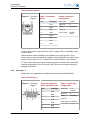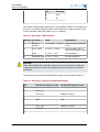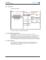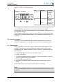
1
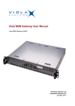
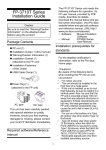
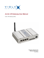
Arctic LTE Gateway User Manual
Arctic LTE Gateway (2625)
Firmware Version 2.4.x
Document Version 1
June 2012
User Manual
Arctic LTE Gateway
Copyright and Trademark
Copyright © 2008-2010, Viola Systems Ltd. All rights to this manual are owned
solely by Viola Systems Ltd. (referred elsewhere in this User’s Manual as
Viola Systems). All rights reserved. No part of this manual may be transmitted
or reproduced in any form or by any means without a prior written permission
from Viola Systems.
Ethernet™ is a trademark of XEROX Corporation. Windows™ and Internet
Explorer™ are trademarks of Microsoft Corporation. Netscape™ is a
trademark of Netscape Communications Corporation. All other product names
mentioned in this manual are the property of their respective owners, whose
rights regarding the trademarks are acknowledged.
Viola Systems Ltd.
Lemminkäisenkatu 14-18 A
FI-20520 Turku
Finland
E-mail: [email protected]
Technical Support
Phone: +358 20 1226 226
Fax: +358 20 1226 220
E-mail: [email protected]
Internet: http://www.violasystems.com
Firmware Version 2.4.x
2
Document Version 1
User Manual
Arctic LTE Gateway
Disclaimer
Viola Systems reserves the right to change the technical specifications
or functions of its products or to discontinue the manufacture of any of its
products or to discontinue the support of any of its products without any
written announcement and urges its customers to ensure that the information
at their disposal is valid.
Viola software and programs are delivered “as is”. The manufacturer does not
grant any kind of warranty including guarantees on suitability and applicability
to a certain application. Under no circumstance is the manufacturer or the
developer of a program responsible for any damage possibly caused by the
use of a program. The names of the programs as well as all copyrights relating
to the programs are the sole property of Viola Systems. Any transfer, licensing
to a third party, leasing, renting, transportation, copying, editing, translating,
modifying into another programming language or reverse engineering for any
intent is forbidden without the written consent of Viola Systems.
Viola Systems has attempted to verify that the information in this manual is
correct with regard to the state of products and software on the publication
date of the manual. We assume no responsibility for possible errors which
may appear in this manual. Information in this manual may change without
prior notice from Viola Systems.
Firmware Version 2.4.x
3
Document Version 1
User Manual
Arctic LTE Gateway
Declaration of Conformity
(according to ISO/IEC Guide 22 and EN 45014)
Manufacturer’s Name: Viola Systems Ltd.
Manufacturer’s Address:
Lemminkäisenkatu 14-18 A
FI-20520 Turku
Finland
declares that this product:
Product Name:
Arctic LTE Gateway
conforms to the following standards:
EMC:
EN 55022 Emission Test (Class A)
1. Radiated Emissions (30-1000MHz)
2. Conducted Emissions (0.15-30MHz)
EN 50082-1 Immunity Test
1. IEC 801-3: Radio Frequency Electromagnetic Field
2. IEC 801-2: Electrostatic Discharge
3. IEC 801-4: Fast Transients, AC Power Ports and Signal cables
Supplementary Information:
“The product complies with the requirements of the Low Voltage Directive
73/23/EEC and EMC directive 89/336/EEC.”
Warning!
This is a Class A product. In a domestic environment this product may cause
radio Interference which may make it necessary for the user to take adequate
measures.
Manufacturer’s Contact Information:
Viola Systems Ltd.
Lemminkäisenkatu 14-18 A
FI-20520 Turku
Finland
Phone: +358 20 1226 226
Fax: +358 20 1226 220
Firmware Version 2.4.x
4
Document Version 1
User Manual
Arctic LTE Gateway
Warranty and Safety Instructions
Read these safety instructions carefully before using the products mentioned
in this manual:
Warranty will be void if the product is used in any way in contradiction with the
instructions given in this manual or if the product has been tampered with.
The devices mentioned in this manual are to be used only according to the
instructions described in this manual. Faultless and safe operation of the
devices can be guaranteed only if the transport, storage, operation and
handling of the devices is appropriate. This also applies to the maintenance of
the products.
To prevent damage both the product and any terminal devices must always
be switched OFF before connecting or disconnecting any cables. It should
be ascertained that different devices used have the same ground potential.
Before connecting any power cables the output voltage of the power supply
should be checked.
This product is not fault-tolerant and is not designed, manufactured
or intended for use or resale as on-line control equipment or as part
of such equipment in any hazardous environment requiring fail- safe
performance, such as in the operation of nuclear facilities, aircraft navigation
or communication systems, air traffic control, direct life support machines,
or weapons systems, in which the failure of Viola Systems manufactured
hardware or software could lead directly to death, personal injury, or severe
physical or environmental damage.
Firmware Version 2.4.x
5
Document Version 1
User Manual
Arctic LTE Gateway
Revisions
Date
Document
Version
Firmware
Version
Description of Changes
06/2012
1.0
2.4.x
First version
Firmware Version 2.4.x
6
Document Version 1
User Manual
Arctic LTE Gateway
Contents
COPYRIGHT AND TRADEMARK ........................................................................................ 2
DISCLAIMER..........................................................................................................................3
DECLARATION OF CONFORMITY...................................................................................... 4
WARRANTY AND SAFETY INSTRUCTIONS.......................................................................5
REVISIONS............................................................................................................................ 6
1. INTRODUCTION............................................................................................................... 9
1.1
1.2
1.3
About the Arctic LTE Gateway............................................................................................. 9
Arctic LTE features................................................................................................................9
Packaging information........................................................................................................... 9
2. HARDWARE DESCRIPTION.......................................................................................... 10
2.1
2.2
2.3
Front panel.......................................................................................................................... 10
Back Panel.......................................................................................................................... 10
LEDs.................................................................................................................................... 11
2.3.1 Status LEDs............................................................................................................ 11
2.3.2 Ethernet LEDs.........................................................................................................12
2.4 Networking........................................................................................................................... 12
2.4.1 Mobile WAN............................................................................................................ 12
2.4.2 Ethernet WAN......................................................................................................... 12
2.4.3 Ethernet LAN...........................................................................................................13
2.5 Serial ports.......................................................................................................................... 13
2.5.1 Serial console port.................................................................................................. 13
2.5.2 Serial port 1............................................................................................................ 14
2.5.3 Serial port 2............................................................................................................ 16
2.6 Power switch and reset button........................................................................................... 16
2.7 Power connector..................................................................................................................16
2.8 Antenna connector.............................................................................................................. 17
2.9 SIM card slots..................................................................................................................... 17
2.10 DIN rail mounting................................................................................................................ 18
2.11 Product label....................................................................................................................... 18
2.12 Accessories..........................................................................................................................18
3. QUICK INSTALLATION...................................................................................................19
3.1
3.2
3.3
3.4
3.5
3.6
Connection Principle............................................................................................................19
Connecting cables............................................................................................................... 19
Logging in to Arctic LTE..................................................................................................... 19
Configuring Ethernet LAN................................................................................................... 21
Configuring Mobile WAN.....................................................................................................22
Configuring default gateway................................................................................................22
4. NETWORK CONFIGURATION....................................................................................... 23
4.1
Configuration screens..........................................................................................................23
4.1.1 Host and domain names.........................................................................................23
4.1.2 Ethernet WAN......................................................................................................... 24
4.1.3 Mobile WAN............................................................................................................ 24
4.1.4 WAN Failover.......................................................................................................... 25
4.1.5 Ethernet LAN...........................................................................................................26
Firmware Version 2.4.x
7
Document Version 1
User Manual
Arctic LTE Gateway
4.2
4.3
4.4
4.1.6 Network monitor...................................................................................................... 26
Routing.................................................................................................................................27
4.2.1 Routing parameters.................................................................................................27
4.2.2 Default route............................................................................................................27
4.2.3 WAN redundancy/failover........................................................................................27
4.2.4 Routing serial <-> Ethernet.....................................................................................28
Network services................................................................................................................. 28
4.3.1 DNS proxy...............................................................................................................28
Network status information..................................................................................................28
4.4.1 System status screen..............................................................................................28
4.4.2 Mobile WAN status LEDs....................................................................................... 28
4.4.3 Modem info screen................................................................................................. 29
5. SERIAL PORT CONFIGURATION................................................................................. 30
5.1
Configuring serial gateway..................................................................................................30
6. ADDITIONAL SYSTEM CONFIGURATION.................................................................... 31
6.1
6.2
6.3
6.4
6.5
6.6
Changing system password................................................................................................ 31
Date and time......................................................................................................................31
System log...........................................................................................................................31
Factory default settings....................................................................................................... 31
Firmware update..................................................................................................................31
Configuration profiles...........................................................................................................32
7. TROUBLESHOOTING.....................................................................................................33
SPECIFICATIONS .............................................................................................................. 34
LIMITED WARRANTY......................................................................................................... 35
TECHNICAL SUPPORT ..................................................................................................... 36
Firmware Version 2.4.x
8
Document Version 1
User Manual
Arctic LTE Gateway
1 Introduction
1.1
About the Arctic LTE Gateway
The Arctic LTE Gateway product is an industrial grade wireless router for
demanding IP connectivity applications.
For the rest of this documentation, the Arctic LTE Gateway is referred to as
Arctic LTE.
1.2
Arctic LTE features
Arctic LTE offers different advanced features. Flexible design allows the
system to gain extra features if required.
High speed wireless connectivity
Arctic LTE has support for the latest mobile technologies, such as LTE
in 4G network and HSPA+ in 3G network. This allows the remote control
of wide bandwidth services such as video surveillance or high amount of
measurement and control channels.
Flexible routing
Arctic LTE can be configured to fit in all kinds of networks. It also has full
support for Serial - Ethernet routing of industrial network protocols.
High security
Arctic LTE has highly configurable firewall and secure VPN support for
secured connectivity.
Redundancy and reliability
Arctic LTE offers redundancy against network breakdowns and remote
VPN endpoint breakdowns. This allows the overall system to achieve high
availability numbers. These functionalities added to high reliability of both
the hardware and software make very robust system suitable in harsh and
demanding industrial environments.
Remote management
Arctic LTE can be managed remotely and it is easy to move configurations
between units.
1.3
Packaging information
The product package should contain the following items:
■ Arctic LTE device
■
3-pin power connector
■
Antenna
■
Arctic LTE Quick Start Guide
■
Arctic LTE Gateway
Additional accessories are also available. For more information, see section
Accessories on page 18.
Firmware Version 2.4.x
9
Document Version 1
User Manual
Arctic LTE Gateway
2 Hardware description
This section describes the physical interfaces on Arctic LTE.
2.1
Front panel
Arctic LTE front panel is shown in figure 1.
Figure 1. Front Panel
LEDs and switches (from left to right) with section reference to more detailed
information:
1. Reset button (Power switch and reset button on page 16)
2. Error LED (section LEDs on page 11)
3. Ethernet WAN port (section Ethernet WAN on page 12)
4. Ethernet LAN ports (section Ethernet LAN)
5. LEDs (section LEDs on page 11)
6. Serial console port (section Serial console port on page 13)
7. SIM card slots (section SIM card slots on page 17)
2.2
Back Panel
Arctic LTE back panel is shown in figure 2.
Figure 2. Back Panel
Connectors (from left to right):
1. Serial port 1 (section Serial port 1 on page 14)
2. Serial port 1 configuration DIP switches (section Serial port 1 on page
14)
3. Serial port 2 (section Serial port 2 on page 16)
Firmware Version 2.4.x
10
Document Version 1
User Manual
Arctic LTE Gateway
4. Power switch
5. Power connector (section Power connector on page 16)
6. Antenna connector (section Antenna connector on page 17)
2.3
2.3.1
LEDs
Status LEDs
Arctic LTE has 11 status LEDs. They are located on the front panel (see
section Front panel).
Table 1: LED Description
LED State
Meaning
Error On
Unit is restarting. LED should turn off after restart (usually about 30
seconds). If the LED is constantly turned on for a long time, contact
technical support.
Blinking There is something wrong with the unit or the power supply causes
the unit to restart constantly. Try with another power supply and if
that does not help, contact technical support.
Off
RUN
VPN
Unit is operating normally.
Blinking Unit is operating normally
Off
If the unit is turned on and RUN led is not blinking, the system has
catched an error and is waiting for restart. The unit should restart
soon.
On
VPN connection is up
Blinking VPN connection is starting
Off
VPN connection is disabled
FW
-
Reserved for future use
SIM
On
SIM card has been found and it is ready for use.
Blinking SIM card initialization is in progress.
SIG
Off
SIM card is not in use
On
Signal level is normal or good (better than -95 dBm)
Blinking Signal level is weak (between -110 dBm and -95 dBm)
Off
COM On
There is no signal (below -110 dBm)
Connection is up
Blinking Connection is starting. If the connection is not coming up, check the
SIM and SIG LEDs
Off
Connection is stopped
APP
-
Reserved for future use
USR
-
Reserved for future use
RS1
-
Reserved for future use
RS2
-
Reserved for future use
Firmware Version 2.4.x
11
Document Version 1
User Manual
Arctic LTE Gateway
2.3.2
Ethernet LEDs
All Ethernet ports have two LEDs to indicate the ports link and activity status.
Table 2: Ethernet LED description
LED
State
Meaning
Green
On
Link on
Blink
Data received
Off
Link off
On
Full duplex
Off
Half duplex
Yellow
2.4
2.4.1
Networking
Mobile WAN
Arctic LTE has a high speed wireless functionality which allows the use of
bandwidth demanding wireless applications.
Table 3: Mobile WAN specifications
2.4.2
Networks
Frequencies
LTE, LTE
800/900/1800/2100/2600 MHz
UMTS (HSPA+), WCDMA
900/2100 MHz
EDGE/GPRS/GSM
900/1800/1900
Ethernet WAN
Arctic LTE has one physical port for Ethernet WAN. Specifications are shown
in table 4.
Table 4: Ethernet WAN specifications
Figure 3. Connector
Number of
ports
1
Speed
10Base-T,
100Base-TX
Duplex
Half and Full
Autonegotiation
Yes
Recommended Cat5 or better
cabling
Firmware Version 2.4.x
12
Document Version 1
User Manual
Arctic LTE Gateway
If Ethernet WAN interface is directly connected to computer, crossover cable
must be used. Ethernet WAN interface does not support automatic MDI/MDIX
detection.
2.4.3
Ethernet LAN
Arctic LTE has three physical ports for Ethernet LAN. These ports are
connected to a common switch. Specifications are shown in table 5.
Figure 4.
Table 5: Ethernet LAN Specifications
Speed
10Base-T, 100Base-TX
Duplex
Half and Full
Auto-negotiation
Yes
Recommended cabling
Cat5 or better
If Ethernet LAN interface is directly connected to computer, both crossover
and straight cables can be used. Ethernet LAN interface supports automatic
MDI/MDIX detection.
2.5
Serial ports
Arctic LTE has two application serial ports and one serial console port.
Serial port 1 is configurable to multiple serial formats (RS-232/422/485), while
serial port 2 supports only RS-232 data mode.
Serial port connectors are 9-pin D-sub (male) connectors. Serial ports enact
as DTE devices.
2.5.1
Serial console port
Serial console connector is located in Arctic LTE front panel (see figure 1).
Connector type is RJ45. Connector is described in table 6.
Firmware Version 2.4.x
13
Document Version 1
User Manual
Arctic LTE Gateway
Table 6: Serial console
Figure 5. Connector
diagram
Table 7: Connector
pinout
Table 8: Serial port
configuration
Pin
Function
Baud rate
115200
1
CTS
Data bits
8
2
DSR
Parity
No parity
3
RXD
Stop bits
1
4
GND
Flow control
5
GND
No flow
control
6
TXD
7
DTR
8
RTS
Console port can be connected from a PC by using a Cisco compatible serial
console cable.
Ethernet serial console adapters are available from Viola Systems. They
allow serial console access with the adapter and straight Ethernet cable. Viola
Systems order code is 3170. Contact the local sales office for more details.
To open serial console access a terminal program is needed. Recommended
terminal programs are Tera Term and Putty. Open the connection using the
settings from table 7.
2.5.2
Serial port 1
Serial port 1 is configurable to multiple serial formats (RS-232/422/485).
Table 9: Serial port 1
Figure 6. Connector
diagram
Firmware Version 2.4.x
Table 10: Connector
pinout (RS-232 mode)
Pin
Function
1
DCD
2
RXD
3
TXD
4
DTR
5
GND
6
DSR
7
RTS
14
Table 11: Serial port
configuration
Baud rate
115 230400
Data bits
8
Parity
No parity
Stop bits
1
Flow control CTS/RTS
Document Version 1
User Manual
Arctic LTE Gateway
Pin
Function
8
CTS
9
RI
DIP switch configuration for serial port 1 is described in table 12. By default all
are set to "0" position (RS-232 mode). DIP switches 2-4 apply only when port
is set in RS-485 mode (DIP switch 1 on "1" position).
Table 12: Serial port 1 DIP switches
Number Function
State
Explanation
1
RS-232 /
RS-485
0 = RS-232, 1 = RS-485
Selects serial port operation
mode
2
FULL / HALF
0 = FULL, 1 = HALF
Selects between half ( 2wire) and full duplex (4-wire)
3
BIAS
0 = OFF, 1 = ON
RS-485 biasing
4
TERMINATION 0 = OFF, 1 = ON
RS-485 termination
Warning!
Make sure that RS-422 or RS-485 cables are not connected to a serial port
configured to RS-232 mode. This can damage the port and the connected
equipment.
Serial port pinouts in RS-422 and RS-485 modes are described in table 13.
Table 13: Serial port 1 pinouts in RS-422/485 modes
Pin
RS-485 full-duplex (4-wire) RS-485 half-duplex (2-wire)
1
-
-
2
RXD+ (in)
-
3
TXD- (out)
TXD/RXD- (out/in)
4
-
-
5
GND
GND
6
-
-
7
TXD+ (out)
TXD/RXD+ (out/in)
8
RXD- (in)
-
9
-
-
Firmware Version 2.4.x
15
Document Version 1
User Manual
Arctic LTE Gateway
2.5.3
Serial port 2
Table 14: Serial port 2
Figure 7. Connector diagram Table 15:
Table 16: Serial port
Connector pinout configuration
Pin
Function Baud rate
1
DCD
2
RXD
3
TXD
4
DTR
5
GND
6
DSR
7
RTS
8
CTS
9
RI
115 230400
Data bits
8
Parity
No parity
Stop bits
1
Flow
control
No flow
control
Serial port 2 supports only RS-232 data mode.
2.6
Power switch and reset button
Power switch is located on back panel. It turns the unit on and off.
Reset button is located on front panel. Press shortly to reset the unit. Reset
button can be used to restore factory default settings. To restore factory
default settings, reset the unit by keeping the reset button pressed down until
all the status LEDs blink. This indicates the factory presets have been applied.
2.7
Power connector
Arctic LTE has a 3-pin power connector. Pinout and voltage limits are
described in table 17. Supplied plug type is Phoenix Contact MC 1,5 / 3STF-3,5 with screw fastening.
Firmware Version 2.4.x
16
Document Version 1
User Manual
Arctic LTE Gateway
Table 17: Power supply connector
Figure 8. Connector
Pin
Symbol
Function
1
+
Voltage in,
positive /
11 ... 18
VDC, 400
mA
2
-
Voltage in,
negative
3
GND
Extra ground
connection
Arctic LTE can be also used with 2-pin power connector, pin 3 left
unconnected. The unit is protected against reversed polarity within the limits of
the specified voltages.
Viola Systems default power supply for Arctic LTE can be ordered with order
code 3020. Note that the power supply is not included in standard Arctic LTE
package.
2.8
Antenna connector
The Arctic LTE has a FME antenna connector (male type) for an external
antenna. It is possible to use any kind of external 50 Ω quad-band antenna.
2.9
SIM card slots
Arctic LTE wireless connection requires SIM card with data transfer service
enabled. The device can use two SIM cards, which can be used to make
connection to two different operators. Arctic LTE can be operated using only
one SIM card.
To operate with SIM card follow the procedure below:
1. Power off the Arctic.
2. The SIM card holder contains a tray with a yellow eject button. Push this
button to eject the tray from the holder.
3. Put the SIM card onto the tray.
4. Insert the tray carefully back to the holder and press the tray until it is
locked.
If two SIM card are used, repeat the procedure for SIM slot 2.
Note!
It is not recommended to insert or remove the SIM card while the Arctic LTE is
turned on.
Firmware Version 2.4.x
17
Document Version 1
User Manual
Arctic LTE Gateway
2.10
DIN rail mounting
Arctic LTE has mounting holes for optional DIN rail mounting brackets. Viola
Systems order code for DIN rail mounting kit is 3003. Contact the local Viola
Systems distributor for more details.
Mounting instructions:
1. Required tools and accessories are: DIN rail mounting kit (2 mounting
brackets and 4 screws), screw driver.
2. Use the screw driver to attach the screws to bthe ottom panel of the Arctic
LTE. DIN rail brackets are installed to either diagonally or horisontally
depending on the wanted DIN rail installation angle.
2.11
Product label
Product label is found on the bottom of the device and it contains the basic
information about the unit such as product name, serial number and Ethernet
MAC address.
Figure 9. Product label
2.12
Accessories
Viola Systems supplies certain accessories for Arctic LTE. Possible
accessories are listed in table 18.
Table 18: Arctic LTE accessories
Accessory
Order code
Serial console adapter: RS232 to RJ45
3170
DIN rail monting kit: 2 DIN rail clips with screws
3003
Optional power supply: 12V/1.5A with universal 100-240VAC
IEC input
3020
Accessory kit: Serial console adapter, Ethernet cables, power
supply
3221
Firmware Version 2.4.x
18
Document Version 1
User Manual
Arctic LTE Gateway
3 Quick Installation
This chapter describes how to configure the WAN network interfaces on Arctic
LTE.
3.1
Connection Principle
Arctic LTE has three network interfaces, Ethenet WAN, Mobile WAN and
Ethernet LAN. WAN interfaces are used for connecting Arctic LTE to public
Internet or private APN. Ethernet LAN is used for connecting other Ethernet
devices to Arctic LTE's local network.
WAN interfaces can be configured to get redundant system where one WAN
automatically gets traffic if the other one goes down. For example, if the
Ethernet LAN goes down, the traffic is automatically switched to mobile
WAN and back when the Ethernet interface comes up again. This way the
availability of the remote system is better than with just one interface.
3.2
Connecting cables
1. Verify that the power switch is in the OFF position.
2. Connect the Ethernet cable between Arctic LTE (Ethernet LAN connector)
and the computer used for the configuration.
3. Connect power supply to Arctic LTE and toggle power the switch to ON
position.
4. The error LED should turn on immediately after the power switch turned
on.
5. After the system has initialized, the Error LED turns off and the RUN LED
starts to blink.
3.3
Logging in to Arctic LTE
This section describes how to log in to Arctic LTE using web configuration
menu.
Firmware Version 2.4.x
19
Document Version 1
User Manual
Arctic LTE Gateway
1. Configure the computer to use the same IP address space than Arctic LTE
(laptop IP for example 10.10.10.11 with netmask 255.0.0.0). Check with
ping command.
2. Connect to the Arctic LTE using the web browser. The default IP address
of Arctic LTE is 10.10.10.10 (netmask 255.0.0.0). Please make sure to
connect to a HTTPS port (see figure 13).
Figure 10. Browser https example
Note!
The browser request for the certificates and can be ignored at this point.
Firmware Version 2.4.x
20
Document Version 1
User Manual
Arctic LTE Gateway
3. Enter the username and password and press Login button in the log-in
screen.. The actual screen depends on the used web browser.
Note!
Default username is viola-adm and default password is violam2m. It is
recommended that the default password is changed before the product is
connected to a public network.
4. White texts on the blue background on the left are the primary navigation
texts and they are always visible on the screen. Individual screens may
have their own tabs which split the configuration fields on larger screens.
See figure 14.
Figure 11. Configuration menu
3.4
Configuring Ethernet LAN
1.
2.
3.
4.
Select Network->Ethernet LAN from the left menu.
Enter the preferred configuration to the configuration fields.
Press Submit button on the bottom to save the settings.
Select Tools->Reboot from the left menu and press Reboot button to
restart the unit
Note!
If the IP addresses are changed, the existing web browser connection hangs
up once the settings are applied, so open a new connection to the new IP
address (check the Ethernet cabling)
5. Connect to the Arctic LTE with a new IP address.
Firmware Version 2.4.x
21
Document Version 1
User Manual
Arctic LTE Gateway
3.5
Configuring Mobile WAN
1. Select Network->Mobile WAN from the left menu.
2. Enter the preferred configuration to the configuration fields.
3. Press Submit button on the bottom to save the settings.
3.6
Configuring default gateway
1. Select Network->WAN Failover from the left menu.
2. Set "WAN Default Route"="Yes". This has to be enabled to use either
WAN as default route interface.
3. If the mobile WAN has to be set as a default gateway, set "Primary WAN
Interface"="Mobile WAN".
4. If Ethernet WAN has to be set as a default gateway, set "PrimaryWAN
Interface"="EthernetWAN".
5. If both Ethernet WAN and Mobile WAN configured, define the Backup
WAN Interface. If the primary WAN interface comes down, Arctic LTE
automatically switches default route to backup WAN interface. Figure 15
shows example configuration where Ethernet WAN is configured as default
route.
Figure 12. Ethernet WAN default route example
6. Press Submit on the bottom to save the settings.
7. Select Tools->Reboot from the left menu and press Reboot button to
restart the unit.
Firmware Version 2.4.x
22
Document Version 1
User Manual
Arctic LTE Gateway
4 Network Configuration
4.1
Configuration screens
The web user interface has a navigation menu that is always visible on the
left pane. In the menu, the items are grouped together in sections such as
System, Network, VPN and Firewall.
Figure 13. Web user interface
4.1.1
Host and domain names
Host and domain names can be set from the System General Settings screen.
Firmware Version 2.4.x
23
Document Version 1
User Manual
Arctic LTE Gateway
Figure 14. General Settings
4.1.2
Ethernet WAN
This screen configures the Ethernet WAN interface on Arctic LTE.
Figure 15. Ethernet WAN configuration
Connectivity Monitor settings are used whenWAN redundancy functionality
is wanted. Monitor keeps checking the connection to given remote host to
determine the network status. If the ping does not get an answer for given time
window, it informs the WAN switch logic to try the secondary interface.
If the WAN redundancy is implemented by using two separated Ethernet
connections with different gateways, the Backup Gateway parameter needs to
be configured towards correct backup gateway. Backup Gateway parameter is
not needed if WAN redundancy is implemented with wireless connection.
See section WAN Failover on page 25 for more details about WAN
redundancy.
4.1.3
Mobile WAN
This screen configures the Mobile WAN interface on Arctic LTE.
Firmware Version 2.4.x
24
Document Version 1
User Manual
Arctic LTE Gateway
Figure 16. Mobile WAN configuration
To configure the mobile WAN, enable the connection by selecting
"Enable"="Yes" on the top of the page and enter PIN code if set, APN name
and authentication details if needed.
If Arctic LTE acts as a wireless router to Ethernet devices and DNS is needed,
enter DNS configuration as well. When ready, press the Submit button on the
bottom of the page to save settings.
Arctic LTE need to be restarted before the mobile WAN configuration is active.
4.1.4
WAN Failover
WAN Failover screen configures the default gateway settings on the Arctic
LTE.
Firmware Version 2.4.x
25
Document Version 1
User Manual
Arctic LTE Gateway
Figure 17. WAN Failover configuratio
To enable any default routes, set "WAN Default Route"="Yes". Any route
settings are not effective if this parameter is not enabled.
Set "On Demand"="Yes" if the backup WAN interface to come up only
when primary interface goes down. Disable if both wireless and wired WAN
interfaces have to be up all the time.
4.1.5
Ethernet LAN
This screen configures the Ethernet LAN interface on Arctic LTE.
Figure 18. Ethernet LAN Configuration
Ethernet LAN configuration is very simple. It configures the IP address for the
Ethernet LAN interface.
4.1.6
Network monitor
This screen configures the interface connectivity monitor on Arctic LTE.
Figure 19. Network monitor configuration
Firmware Version 2.4.x
26
Document Version 1
User Manual
Arctic LTE Gateway
When using VPN, the usage of the monitor is heavily recommended to detect
the connection drops.
4.2
4.2.1
Routing
Routing parameters
There are multiple configuration options that define the routing on Arctic LTE:
■ Ethernet WAN - Gateway (IP address)
■ IP address of router used to reach the internet. Leave empty if unused.
4.2.2
■
Ethernet WAN - Backup Gateway (IP address)
■ IP address of backup router used to reach the internet. Leave empty if
unused.
■
WAN Failover - WAN Default Route (selection: Yes/No)
■ Usually "Yes" if default route is defined by "static routes". If the selection
logic is done on VPN level select "No"
■
WAN Failover - On Demand (selection: Yes/No)
■ Select "Yes" to activate the backup interfaces only when required. Select
"No" to have all the WAN interfaces to be available simultaneously for
e.g. VPNs.
■
WAN Failover - Primary WAN Interface (selection: None/Mobile WAN/
Ethernet WAN/Ethernet WAN Secondary)
■
WAN Failover - Backup WAN Interface(selection: None/Mobile WAN/
Ethernet WAN/Ethernet WAN Secondary)
■
WAN Failover - Secondary Backup WAN Interface (selection: None/Mobile
WAN/Ethernet WAN/Ethernet WAN Secondary)
■ These three settings configure the high level default gateways. Must be
configured to enable default route.
■
OpenVPN Client Settings - Interface (selection: Any WAN/Ethernet WAN/
Wireless WAN/Ethernet LAN)
■ Which Interface to use for connection
■
OpenVPN Client Settings - Routing mode (selection: None/host/net/default
route)
■ This defines how the routing is configured with OpenVPN. See
OpenVPN application note.
Default route
Default route can be configured from WAN Failover screen. See section WAN
Failover on page 25.
4.2.3
WAN redundancy/failover
To configure redundancy between WAN interfaces, configure multiple WAN
interfaces to WAN Failover. See section WAN Failover on page 25.
Firmware Version 2.4.x
27
Document Version 1
User Manual
Arctic LTE Gateway
4.2.4
Routing serial <-> Ethernet
See section Configuring serial gateway on page 30 for configuring serial
gateway.
4.3
4.3.1
Network services
DNS proxy
To use this feature, configure the device to use Arctic LTE Ethernet LAN IP
address as its DNS server. This way the DNS queries from the device get
routed thorough the Arctic LTE. To use this feature, configure the device to
use Arctic LTE Ethernet LAN IP address as its DNS server. This way the DNS
queries from the device get routed thorough the Arctic LTE.
4.4
4.4.1
Network status information
System status screen
Network status information can be seen from System->Status screen.
Figure 20. Network status screen
4.4.2
Mobile WAN status LEDs
Status of mobile WAN interface can be viewed from the front panel LEDs. The
initialization sequence is:
Firmware Version 2.4.x
28
Document Version 1
User Manual
Arctic LTE Gateway
1. COM LED starts to blink when the connection is started.
2. SIM LED starts to blink when SIM card is searched and turns on when
card is found and PIN code accepted.
3. SIG LED starts to blink when operator network is searched and gets lit
when the network is found.
4. COM LED gets lit when the connection is up.
4.4.3
Modem info screen
In troubleshooting situations, checking the system logs helps to identify
the problem. Also modem info page can be used to check the status of the
wireless modem.
Figure 21. Modem info screen
Firmware Version 2.4.x
29
Document Version 1
User Manual
Arctic LTE Gateway
5 Serial Port Configuration
5.1
Configuring serial gateway
This section describes how to configure serial <-> Ethernet functionality.
Serial gateway feature enables data from the serial port attached device to be
routed to Ethernet and vice versa. Serial gateway processes the transmitted
data transparently and does not alter it any way except for buffering it for
transmission. Because of the transparent communication, any protocols can
be used in actual communication between nodes.
Figure 22. Serial gateway configuration screen
Serial gateway configuration depends on used protocols.
Both serial ports have their own configuration screens, located in
Applications->Serial Gateway (RS1) and Applications->Serial Gateway
(RS2).
Firmware Version 2.4.x
30
Document Version 1
User Manual
Arctic LTE Gateway
6 Additional System Configuration
6.1
Changing system password
Username and password can be changed from Tools->User Config screen.
It is always recommended to change the password from the factory default
when the Arctic LTE is connected to a public network.
Also console access password can be changed.
Figure 23. User Config screen
6.2
Date and time
Date and time can be changed from System->Time screen. Date and time
can be configured either manually entering the time or automatically from
connected PC.
Figure 24. System time configuration screen
To set time manually, enter the time and then press Submit button.
To copy time from PC, press Copy PC button and answer "Yes" to question
about changing time. Note that the PC may not necessarily have correct time
set and that needs validation. Also note that the copy functionality requires
JavaScript support from the browser.
6.3
System log
System log is visible on the Tools->System Log screen. To refresh the system
log, use web browser reload button.
6.4
Factory default settings
Factory default settings can be applied by restarting the unit pressing down
reset button until the LEDs blink.
6.5
Firmware update
Current running firmware version can be viewed from the System->Status
screen.
Arctic LTE firmware can be updated from the Tools->Firmware Update
screen.
Firmware Version 2.4.x
31
Document Version 1
User Manual
Arctic LTE Gateway
Figure 25. Firmware update screen
Note!
Firmware update erases all the settings on the unit to the factory defaults. It is
recommended to create backup from the old configuration before attempting
to update the firmware.
To update firmware:
1. Verify for a valid firmware on the PC before attempting to update the
firmware.
2. Select Select file button to open file browsing dialog. The actual dialog
depends on the used browser.
3. Select the updated firmware from the file dialog and return to the firmware
update screen.
4. Press Update button to start the firmware update.
5. Confirm the update.
6. The update takes a ew minutes and the unit restarts with factory default
settings when the update is completed.
6.6
Configuration profiles
Profiles can be configured and saved for future use. A several profiles are
created and selected for the activation. It is possible to import, export and
clone profiles, and also reset them to factory default settings.
Figure 26. Configuration profiles
Firmware Version 2.4.x
32
Document Version 1
User Manual
Arctic LTE Gateway
7 Troubleshooting
Q: Wireless WAN is not coming up
A: Check settings, SIM card and signal level. Easy way to check the
connection status is checking the LEDs, see section Mobile WAN status LEDs
on page 28.
Q: OpenVPN is not working
A: For more information, see OpenVPN application note.
Q: Serial ports are not working
A: For more information, see serial port chapter notes. Verify DIP switch
configuration if RS-422 or 485 modes are being used.
Q: Can not access web user interface
A: Web user interface uses HTTPS for secure web access and it must
be specified on the web browser address field like in this example:
https://10.10.10.10.
Q: Cannot access the Internet with laptop connected to Arctic LTE
A: Testing the mobile WAN connection:
1. Configure mobile WAN connection and verify if it connected to the network
2. Connect a laptop to Ethernet LAN
3. Check that S-NAT rule on the firewall is set as "Action"="Masquerade" and
"Destination Inter- face"="Mobile WAN".
4. Check that DNS Proxy is enabled from Services->Common screen.
5. Configure network settings on laptop to use Arctic LTE Ethernet LAN
address as gateway and DNS server.
With these setting, the Internet should be accessible on the laptop.
Firmware Version 2.4.x
33
Document Version 1
User Manual
Arctic LTE Gateway
Specifications
Table 19: Technical specifications
Processor
400MHz
Memory
64MB
Hard Drive
32MB flash
Input voltage (nominal)
12-36VDC
Power consumption
7W max
Power connector
Phoenix Contact MC 1,5/ 3-STF-3,5
Casing
Aluminium sheet
Operating temperature
-25 - 70 °C
Storage temperature
-40 ... +85 C
Humidity
0 ... 99 % non-condensing
Network connection
10/100M
Approvals
CE
Size
165 x 120 x 46 mm
Weight
0.6 kg
Antenna connector type is SSMB-nano.
Table 20: Application serial port specifications
Serial mode (RS1)
RS-232 / 422 / 485
Serial mode (RS2)
RS-232
Baud rate
300 - 460800
Data bit
5/6/7/8
Parity
None / Even / Odd
Stop bits
1/2
Flow control
None / Hardware (RTS/CTS) / Software (XON/
XOFF)
Techical specifications can be changed without notification.
Table 21: Mobile WAN specifications
Networks
Frequencies
LTE, LTE
800/900/1800/2100/2600 MHz
UMTS (HSPA+), WCDMA
900/2100 MHz
EDGE/GPRS/GSM
900/1800/1900
Firmware Version 2.4.x
34
Document Version 1
User Manual
Arctic LTE Gateway
Limited Warranty
Coverage
Viola Systems warrants this hardware product to be free from defects in
materials and workmanship for the warranty period. This non-transferable,
limited warranty is only for the first end-user purchaser. The warranty begins
on the date of purchase and lasts for the period specified below:
Arctic LTE Gateway : one (1) year
Excluded Products and Problems
This warranty does not apply to: (a) Viola Systems software products; (b)
expendable components such as cables and connectors; or (c) third party
products, hardware or software, supplied with the warranted product. Viola
Systems makes no warranty of any kind on such products which, if included,
are provided "AS IS." Excluded is damage caused by accident, misuse, abuse,
unusually heavy use, or external environmental causes.
Remedies
The sole and exclusive remedy for a covered defect is repair or replacement
of the defective product, at Viola Systems’ sole option and expense, and
Viola Systems may use a new or refurbished parts or products to do so. If
Viola Systems is unable to repair or replace a defective product, an alternate
exclusive remedy shall be a refund of the original purchase price.
The above is Viola Systems’ entire obligation to you under this warranty.
IN NO EVENT SHALL VIOLA SYSTEMS BE LIABLE FOR INDIRECT,
INCIDENTAL, CONSEQUENTIAL OR SPECIAL DAMAGES OR LOSSES,
INCLUDING LOSS OF DATA, USE, OR PROFITS EVEN IF VIOLA SYSTEMS
HAS BEEN ADVISED OF THE POSSIBILITY OF SUCH DAMAGES. In no
event shall Viola Systems’ liability exceed the original purchase price of the
device server. Some states or countries do not allow the exclusion or limitation
of incidental or consequential damages, so the above limitation or exclusion
may not apply.
Obtaining Warranty Service
It must be notified to Viola Systems within the warranty period to receive
warranty service. During the warranty period, Viola Systems will repair or
replace, at its option, any defective products or parts at no additional charge,
provided that the product is returned, shipping prepaid, to Viola Systems. All
replaced parts and products become the property of Viola Systems. Before
returning any product for repair, customers are required to contact the Viola
Systems.
Firmware Version 2.4.x
35
Document Version 1
User Manual
Arctic LTE Gateway
Technical Support
Contacting Technical Support
Phone: +358 20 1226 226
Fax: +358 20 1226 220
E-mail: [email protected]
Internet: http://www.violasystems.com
Recording Arctic Information
Before contacting our Technical Support staff, please record (if possible) the
following information about the Arctic product:
Product name:
___________________________________________________
Serial no:
_______________________________________________________
Note the status of the Arctic in the space below before contacting technical
support. Include information about error messages, diagnostic test results, and
problems with specific applications.
___________________________________________________________________
___________________________________________________________________
___________________________________________________________________
Firmware Version 2.4.x
36
Document Version 1