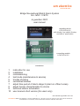
1
1
2
3
4
5
6
8
7
sm electrics
services & more
F2
k2
k3
k3
k4
k4
max. 160mA
2x0,75
2x0,75
4x0,75
2x0,75
2x1,5
2x0,75
max. load: 160mA
k1
max. 160mA
F1
D1
2x m1,25A
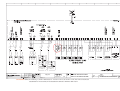
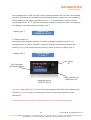
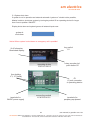
sample system connecting diagram
1
common
AL ST. #3
AL ST. #2
VDR
AL ST. #1
+
2
-
5
6
1
1
2
2
5
5
6
6
ALARM DEVICES
OFFICER'S AREA
STAGE 2 ALARM
75 - 85dB(A), 1m
ALARM DEVICES
OFFICER'S AREA
STAGE 3 ALARM
85 - 112dB(A), 1m
(by using more than 10 indications, use LEDs)
G power supply qualified
F
D VDR link added
modification
23.3.10 T. Streit
18.3.10 T. Streit
4.3.10 T. Streit
name
HULL
Shipyard
T. Streit
spare of:
A4
department:
sme
= -
+ BRIDGE NAVIGATIONAL
class
Drawing No.
WATCH
ALARM
SYSTEM
GL
LCM 210.24.0.0
AS RevG
21
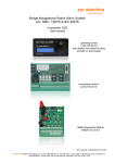
user manual,
le guardian
vers 1.07
sm electrics GmbH, Am Wulfsbarg 17, D-24217 Stakendorf, tel.: +49 4344 41 22 73, fax: 04344 41 35 40, web: www.sm-electrics.de
Geschäftsführer: Thomas Streit, Sitz der Gesellschaft: Stakendorf: HRB Kiel: HRB 7708 KI
1
1