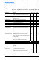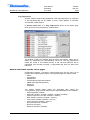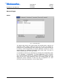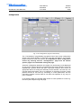
1
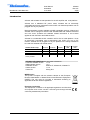
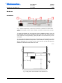
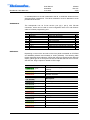
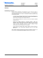
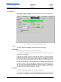
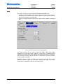
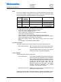
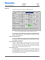
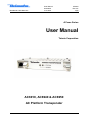
Broadband Cable Networks User Manual 59300028 31.5.2006 AC69x0 Rev.007 1(38) ACcess Series User Manual Teleste Corporation AC6910, AC6940 & AC6950 AC Platform Transponder Broadband Cable Networks User Manual 59300028 31.5.2006 AC69x0 Rev.007 2(38) Introduction AC6910 and AC6950 are transponders for the AC amplifier and node platform. AC6910 has a wideband RF power meter, AC6950 has an electrically controllable tuner level measurement and ALSC unit. Both transponders can be plugged into any AC platform. Both transponders are also available as HMS compatible versions: AC6910 and AC6950 can be changed to AC6910 and AC6950 HMS with software download and vice versa. Therefore all hardware related information in this manual applies to both CATVisor and HMS versions. AC6940 is a modemless ALSC controller unit for the AC node platform. It has an electrically controllable tuner measurement and ALSC unit, but no RF modem. AC6940 can be plugged into any AC platform but is mainly intended to be used with AC8000 and AC800 nodes. AC69x0 feature map CATVisor modem SW HMS modem SW RF power measurement RF level measurement / ALSC possible AC6910 AC6940 ● AC6950 AC6910 HMS AC6950 HMS ● ● ● ● ● ● ● VERSION INFORMATION this document is based on: CATVisor software version 1.11.0 HMS software version 1.4.0 Hardware version AC6910: E, AC6940: B, AC6950: D Viewer version 1.11.0 Viewer file ACx(u).DLL WEEE Notice This product complies with the relevant clauses of the European Directive 2002/96/EC on Waste Electrical and Electronic Equipment (WEEE). The unit must be recycled or discarded according to applicable local and national regulations. European Conformity This equipment conforms to all applicaple regulations and directives of European Union which concern it and has gone through relevant conformity assessment procedures. ● User Manual 59300028 31.5.2006 Broadband Cable Networks AC69x0 Rev.007 3(38) Hardware Installation 1 2 3 4 Fig. 1. AC69x0 Transponder, 1) Service port connection, 2) Indicator for modem status (AC6910 and AC6950) or ALSC status (AC6940), 3) Indicator for station status, 4) Light sensor To install an AC69x0 unit, first locate the correct installation position. Snap off the segments of the shrouds break-away type slot cover and remove the slot cover. Insert the unit by pressing it gently into place. The unit will fit only in one orientation. To carry away the heat from the unit to the housing, a silicon elastomer is used with AC6940 and AC6950 transponders. After installation carefully attach the silicon elastomer (40 x 20 mm) on the cover (see fig. 2). Be sure that the elastomer’s adhesive surface faces the cover. 8604092 Fig. 2. Fitting of the silicon elastomer on the AC1000 cover. User Manual 59300028 31.5.2006 Broadband Cable Networks AC69x0 Rev.007 4(38) In AC8000 platform a shroud is attached to the lid, to shield the electronics from electromagnetic interference. The silicon elastomer must be attached to area provided in the shroud. Connectors The transponder has an RJ-45 service port (fig.1 pos.1) with RS-485 connection, which can be used for local configuration with a PC and DVX021 cable or DVX012 programming unit. Service port connector (shielded RJ-45 socket) Pin Signal Description 1 RS-485 + DVX bus 38400 bps 2 RS-485 DVX bus 38400 bps 3 NC Not connected 4 NC Not connected 5 NC Not connected 6 NC Do not connect 7 +12 V Output for aux equipment (unfused) 8 GND Ground I/O I/O I/O O - Indicators Depending on the unit the two leds on the front panel are labeled as STATION and MODEM (AC6910 and AC6950) or ALSC (AC6940). The following table further describes these indicators. During the power-up sequence both leds will display yellow light for a short period of time to indicate that leds are functional. See also the ‘Flags’ chapter for details of LED usage. STATION LED ██████████ yellow Description No alarms or warnings (other than modem related). At least one warning, no alarms. ██████████ red At least one alarm. MODEM LED (AC6910 and AC6950) Description ██████████ dark Scanning for a communication channel ██████████ green (blinking) Communication channel found. ██████████ green Communication is OK, receiver level OK. ██████████ yellow Communication is OK, receiver level not OK. ██████████ red Internal error. ██████████ green ALSC LED (AC6940) Description ██████████ dark ALSC off. ██████████ green ALSC OK. ██████████ yellow ALSC is saturated or on 1 pilot only. ██████████ red All pilots are missing. Broadband Cable Networks User Manual 59300028 31.5.2006 AC69x0 Rev.007 5(38) Software Establishing connection All the needed configurations and adjustments can be carried out locally or remotely by using the CATVisor Commander software. It is recommended to use Commander version 2.4 or later. A connection to AC69x0 is possible using the following methods: - Local serial port connection between the service port and a COM port of a PC using a DVX021 adapter cable. When connecting, choose Serial Port (point-to-point) connection with 38400 bps data rate. - Local connection between the service port and the DVX012 handheld programming unit. - AC6910 and AC6950: Remote IP connection through a HEC (e.g. DMM201). The IP address has to be set locally before this. It has to match the subnet settings of the DMM’s HFC network interface and it must also be unique for each transponder. Without a valid IP address, remote communication with the transponder is not possible. - AC6910 HMS and AC6950 HMS: Remote SNMP connection through a HMTS. Some of the communication parameters have to be set locally before this. More detailed hardware requirements and software installation instructions can be found from the Commander User Manual supplied with the software. Broadband Cable Networks User Manual 59300028 31.5.2006 AC69x0 Rev.007 6(38) Flags All module flags displayed in Commander and CATVisor EMS with corresponding LED behaviour are described in the table below. Note that if a flag is suppressed, it doesn't affect leds. Alarms (red flag) Temperature high AC voltage low +24V voltage low +12V voltage low Unknown module Transponder internal error Optical Rx#1 level high Optical Rx#1 level low Optical Rx#2 level high Optical Rx#2 level low Tuner module error ALSC error Signal level low Warnings (yellow flag) Temperature low Temperature getting high AC voltage high +24V voltage high +12V voltage high Modem receive level low Modem not connected Optical Tx#1 laser current high Optical Tx#1 laser current low Optical Tx#2 laser current high Optical Tx#2 laser current low Spectrum out of limits ALSC saturated ALSC on 1 pilot only Signal level high Notifies (blue flag) Lid open Return path off Return path -6dB Settings changed Service terminal connected Modem transmit level saturated ALSC main pilot(s) missing ALSC off Description Temperature is over high alarm limit. AC voltage is below low alarm limit. 24V voltage is below low alarm limit. In AC8000 this flag is common for both power supplies. +12V voltage is below low alarm limit. Transponder is not able to recognise and control other module(s). Possible reason is too old embedded software. Transponder has an internal error. If resetting the unit doesn't help, it should be sent to service. Optical receiver #1 power level is over high alarm limit. Optical receiver #1 power level is below low alarm limit. Optical receiver #2 power level is over high alarm limit. Optical receiver #2 power level is below low alarm limit. Internal error in the tuner module (AC6940 and AC6950). If resetting the unit doesn't help, it should be sent to service. All pilots are missing. Not generated if ALSC is switched off. (AC6940 and AC6950) User-defined signal level is below low alarm limit (AC6940 and AC6950) or RF power level is below low alarm limit (AC6910). Station red red Modem ALSC red red red red red red red red red red red red AC6950 red AC6940 red Description Temperature is below low warning limit. Temperature is over high warning limit, but below high alarm limit. AC voltage is above high warning limit. +24V voltage is over high warning limit. In AC8000 this flag is common for both power supplies. +12V voltage is over high warning limit. RF modem receiver level is too low for reliable communication. Generated only if modem is connected. RF modem is not communicating with HEC. Optical transmitter #1 laser current is over high warning limit. Optical transmitter #1 laser current is below low warning limit. Optical transmitter #2 laser current is over high warning limit. Optical transmitter #2 laser current is below low warning limit. Spectrum analyser measurement results are not within high/low limits. (AC6940 and AC6950) ALSC is saturated, i.e. adjustment limits have been reached. Not generated if ALSC is switched off. (AC6940 and AC6950) Upper or lower main and backup pilots are missing, ALSC is controlling gain only, slope is frozen. Not generated if ALSC is switched off, or there is no slope adjustment possibility. (AC6940 and AC6950) User-defined signal level is over high warning limit (AC6940 and AC6950) or RF power level is over high warning limit (AC6910). Station yellow yellow yellow Description Lid sensor light level has been over limit during last minute. Return path is turned off. In AC8000 this flag is common for both return paths. Return path is attenuated 6 dB. In AC8000 this flag is common for both return paths. Unit's settings have been modified by user either locally or remotely during last minute. There has been activity on local service connector during last minute. Commanded transmit level is outside dynamic range, modem transmit level is saturated at minimum or maximum value. Generated only if modem is connected and minimum < maximum. One or both main pilot(s) are missing; ALSC uses backup pilot(s). Not generated if ALSC is switched off. (AC6940 and AC6950) Electrical adjustment module(s) installed but ALSC is switched off by user. Or ALSC switched on by user but electrical adjustment module(s) missing. (AC6940 and AC6950) Station Modem ALSC yellow yellow yellow yellow yellow yellow yellow yellow yellow AC6950 yellow AC6940 yellow AC6950 yellow AC6940 yellow Modem ALSC Broadband Cable Networks User Manual 59300028 31.5.2006 AC69x0 Rev.007 7(38) Flag suppression AC69x0 modules support flag suppression. With flag suppression an irrelevant or not interesting flag can be hidden so that it never appears in CATVisor Commander or EMS system. In Service profile there is a "Flag suppression" button on the Status page which opens the “Flag suppression” window below. The window contains all available flags and their descriptions. Flags can be hidden by deselecting the corresponding check box. The flag suppression masks are saved in non-volatile memory of the unit and therefore will be maintained until manually removed. A suppressed flag does not affect LED indicators. General and module specific viewer pages Configuration displays (=”viewers”) include pages that are the same for all modules and module specific pages. These general pages are always visible: − Status − Configuration − Motherboard − Transponder (except with AC6940) − SNMP (with HMS transponders) − Repair log − Properties The module specific pages below are generated after visiting the “*Configuration*” page and are visible with the specified platforms and modules: − Optical (AC8000 / AC800) − Optical Rx (AC500 / AC1000 / AC2000 + AC6810 / AC6820) − Optical Tx (AC500 / AC1000 / AC2000 + AC684x) − Gain (AC500 / AC1000 / AC2000 + AC617x) − Level control (AC800 / AC8000 + AC617x) − ALSC (AC6940 / AC6950 + AC617x) − RF Levels (AC6940 / AC6950) − RF Power (AC6910) − Spectrum (AC6940 / AC6950) Broadband Cable Networks User Manual 59300028 31.5.2006 AC69x0 Rev.007 8(38) General Pages Status Fig. 3. The Status page The Status page shows unit's present status and possible alarm, warning and notification codes (="flags"). Make sure that the unit does not indicate any module errors or signal warnings. Each status flag is color coded according to its severity. Correct programming and signal adjustment usually turn off the signal warnings. For additional information about status flags, see table of module flag descriptions in the Flags chapter. It is possible to hide the less critical flags by checking the corresponding check box for warnings or notifications. The Flag suppression button (available only in Service profile) opens a new window in which it is possible to hide any flags from the unit. “Flag suppression active” text appears below the “Flag suppression” button whenever at least one flag is suppressed. For more information about flag suppression, see the Flags chapter. Broadband Cable Networks User Manual 59300028 31.5.2006 AC69x0 Rev.007 9(38) Configuration Fig. 4. The Configuration page (AC1000 shown) The “*Configuration*” page displays a graphical view of the current configuration similar to the actual amplifier or node layout and also generates a set of viewer pages individual to each active device. It is important to start a configuration session by selecting first the “*Configuration*” page since the module specific pages are created after visiting this page. Automatic configuration detection can identify only active plug-in units displayed as gray boxes. Passive devices are identified by blue texts. Selecting a text tag representing a passive device will open a pull down selection list in which an appropriate device according the assembly can be selected. The user also can type the desired information (up to 12 characters, 6 characters for fuses). These passive devices do not have any monitoring or control parameters, and the information entered in these fields do not affect unit operation in any way, it's just a "checklist". In the AC6910 HMS and AC6950 HMS viewers it is also possible to control e.g. the return path relays through this page. User Manual 59300028 31.5.2006 Broadband Cable Networks AC69x0 Rev.007 10(38) Motherboard Fig. 5. The Motherboard page (AC500 / AC800 / AC1000 version shown) The “Motherboard” page is slightly different in AC2000 and AC8000 because of the two return path controls and power supplies. Return path The “Return path” frame consists of three radio-buttons, which are used to control behavior of the return path. Note that the incoming return path RF signal will be completely cut off by the “Off” selection and will thus also disconnect all other transponders behind this AC amplifier or node. In AC2000 and AC8000 platform there are two independent return path controls. Misc A light sensor in the front panel of the AC69x0 unit (fig. 1 pos. 4) provides indication for the “Lid state”. In dark environment the lid status field may display “Closed” even if the lid is opened. The background color of this field will change to blue to indicate a notification. A green background color is used for the “Closed” status. The “Service terminal” data field shows the status information about the service port connection. If there has been activity on the local service connector during the last minute, the “Service terminal” data field will display “ON”. The background color of this field will change to blue to indicate a notification. A green background color is used for the “OFF” status Measurements and limits This frame is used to show both read-only information about the present voltages and temperature as well as their editable warning and alarm limits. In case these limits are reached the unit raises a warning or alarm flag. Correspondingly the background color of the measurement data fields changes to indicate the change. A green background means legal values; red is the symbol for an alarm and yellow for a warning. Broadband Cable Networks User Manual 59300028 31.5.2006 AC69x0 Rev.007 11(38) The “Deadband” fields indicate the threshold needed to turn off the alarm flag. E.g. a deadband of 0.2 V implies that the flag is turned off when the level is both between the limit values and 0.2 V past the warning limit. The deadbands are read-only information. The “Temperature” fields show the limits for temperature levels of the unit. There are separate warning and alarm limits for high temperature, editable in "Service" user profile. The factory default limits are defined separately for each platform based on their average internal vs. ambient temperature. The “AC voltage” field shows RMS value (DC+AC component) of the remote supply voltage. This value is calculated using sliding average and thus will react slowly to changes. The limits are editable in "Service" user profile. The factory default limit values are quite broad and should be adjusted according to the true AC voltage used, if more accurate monitoring is required. The “+24 V” and “+12 V” fields show the transponder’s internal operating voltage values. The limits are editable in "Service" user profile and shouldn't be changed in normal operation AC8000 can be equipped with double power supplies, hence the second “+24 V #2” field. Note that if only one power supply is installed, the corresponding low voltage alarm limit should be set to zero to avoid false low voltage alarms. There is also a possibility to connect one external voltage or alarm line to AC8000 and monitor its status through "+24 V #2" field instead of the second PSU's +24 V voltage. Broadband Cable Networks User Manual 59300028 31.5.2006 AC69x0 Rev.007 12(38) Transponder (non-HMS) This page is visible only with non-HMS AC6910 and AC6950 transponders. Fig. 6. The Transponder (non-HMS) page The “Transponder” page displays all the data and settings of the transponder’s RF modem. After reset the unit will start the search for HEC (headend controller) carrier within the transponder’s tuning range and start the communication. The HEC will then set communication parameters such as transmitter frequency and transmitter level. Connection status The current communication status between the transponder and HEC is shown in the “Connection status” field with - “Scanning” (yellow); searching for the HEC carrier wave. “Data carrier found” (yellow); waiting for communication parameters. “Registering” (yellow); registration in progress. “Connected” (green); registration complete, communication OK. The number in parenthesis is a more detailed status indicator for diagnostics purposes, ranging from 0 to 11. Receiver The “Frequency” data field shows the used receiver frequency. The “Level” data field shows the measured signal level. A green background indicates legal values and yellow values below the receiver’s dynamic range. The “Scan start” and “Scan stop” fields determine the frequency band that the unit scans through when searching for the HEC carrier. Scanning can be disabled by setting the start and stop frequencies to the same value. Scanning speed can be improved by limiting the scanning range. The default and Broadband Cable Networks User Manual 59300028 31.5.2006 AC69x0 Rev.007 13(38) maximum range is 85…118 MHz. The scan will start from the last known HEC carrier frequency. The “Scan step” field sets the frequency increments of the scanning process, default and minimum value is 0.1 MHz. Changing any of these fields will reset RF modem communication. Transmitter The “Frequency” data field shows the used transmitter frequency commanded by the HEC. The “Level” data field shows the transmitter signal level. The background color of the “Level” data field changes to indicate a notification. A green background indicates legal values and blue color indicates that the transmit level is saturated (i.e. HEC commands a higher or lower level that can be used). The range for transmit signal level can be set in the “Min level” and “Max level” fields. The default and maximum range is 80…95 dBμV. Changes in these values will be taken into use immediately if HEC’s ALC is enabled and will not reset RF modem communication. Communication settings The “IP address” field is used to define the IP address of the unit. The address has to be unique and match the HEC’s IP subnet settings to ensure proper operation and IP level communication with the HEC. The “Net mask” field defines the corresponding IP subnet. It is only needed for broadcast software updates and has to be set according to the HFC subnet of the HEC; otherwise it can be left as 255.255.255.255. The “MAC address” is the unit’s unique, read-only hardware address. Manageable devices in the same HFC network can be divided into different device groups. The “Device group” check boxes can be used to group transponders under multiple HECs. Changing any of these fields will reset RF modem communication. Packet statistics The “Received” field displays the total number of IP packets addressed to and received by this unit. The “Sent” field displays the total number of IP packets sent by this unit. The “Bad” field displays the number of all bad packets received (whether addressed to this unit or not) and is a good indicator of the forward path condition. The "Reset" button will reset all packet counters to zero. Broadband Cable Networks User Manual 59300028 31.5.2006 AC69x0 Rev.007 14(38) Transponder (HMS) This page is visible only with AC6910 HMS and AC6950 HMS transponders. Fig. 7. The Transponder (HMS) page The “Transponder” page displays all the data and settings of a HMS transponder’s RF modem. After the power-up sequence the unit will start the search for HMTS (Hybrid Management Termination System) carrier within the transponder’s tuning range and start the communication. The HMTS will then set communication parameters such as transmitter frequency. Status The current communication status between the transponder and HMTS is shown in the “Connection status” field with - “Initialising modem” (yellow) “Setting receiver” (yellow) “No data carrier” (yellow) “Waiting for channel info” (yellow) "Setting TX frequency” (yellow) “Waiting for TX stabilisation” (yellow) “Setting TX level” (yellow) “Preparing registration” (yellow) “Starting registration” (yellow) “Registration in progress” (yellow) “Waiting for confirmation” (yellow) “Registration complete” (green) Uptime The “Uptime” field shows the time since the last reset or power up. The format is days, hours, minutes and seconds. Broadband Cable Networks User Manual 59300028 31.5.2006 AC69x0 Rev.007 15(38) Receiver The “Frequency” data field shows the used receiver frequency. The “Level” data field shows the measured signal level. A green background indicates legal values and yellow values below the receiver’s dynamic range. The “Scan start” and “Scan stop” fields determine the frequency band that the unit scans through when searching for the HEC carrier. Scanning can be disabled by setting the start and stop frequencies to the same value. The scanning speed can be improved by limiting the scanning range. The default and maximum range is 85…118 MHz. The scan will start from the last known HMTS carrier frequency. The “Scan step” field sets the frequency increments of the scanning process. Transmitter The “Frequency” data field shows the used transmitter frequency commanded by the HMTS. The “Level” data field shows the transmitter signal level and can be edited within the unit's output level range 80…95 dBμV. Addresses The “IP address” field is used to define the IP address of the unit. The address has to be unique and match the HMTS’s IP settings to ensure proper operation and IP level communication with the HMTS. The “Addresses” group box shows also the unicast MAC address as well as the configurable Multicast MAC address. Timeouts The “CHNLDESC” timeout defines how long to wait for the channel descriptor datagram. This value should match with the channel descriptor transmit interval on the HMTS so that the transponder timeout should be longer than the transmit interval. Therefore the default value is set to 35 seconds, to match with the 30 second transmit interval defined as maximum by the HMS standards. − CHNLDESC timeout is used to distinguish a valid HMS channel. After the transponder has detected an RF carrier, it must wait for the CHNLDESC datagram to get the transmitter (and receiver) frequency information. After that it can begin the registration process. If a valid CHNLDESC is not received during the timeout interval, the scanning advances. When the transponder is in the registered state, the handling of the CHNLDESC timeout is slightly different. In order to stay registered, the MAC layer must receive regular CHNLDESC packets. As there is always the possibility that a datagram is corrupted, the used timeout is set to twice as long as the set timeout, to allow one lost CHNLDESC datagram. After that, the transponder declares the forward channel lost and starts to scan for another channel. The “Poll” timeout is used in the registered state If the transponder does not receive any packets to its own MAC address during the MAC poll interval, it restarts the registration process, provided that the forward channel is present and a CHNLDESC is received. Setting the “Poll” timeout to zero disables the timeout handling and enables non-polling use of the communication channel. Thus the transponder stays registered as long as the forward channel is sending CHNLDESCs or the transponder is not reset or commanded to re-register by the HMTS. Broadband Cable Networks User Manual 59300028 31.5.2006 AC69x0 Rev.007 16(38) MAC The “MAC” group box allows the user to control the various parameters used in the backoff process, in case a collision happens in the return path transmission. Correct backoff values parameters are essential to the communication and changing the values from the shown default values should be done only based on careful planning. Packet statistics The “Received” field displays the total number of IP packets addressed to and received by this unit. The “Bad” field displays the number of all bad packets received (whether addressed to this unit or not) and is a good indicator of the forward path condition. Broadband Cable Networks User Manual 59300028 31.5.2006 AC69x0 Rev.007 17(38) SNMP This page is visible only with AC6910 HMS and AC6950 HMS transponders. Fig. 8. The SNMP page This page is used to control the SNMP agent parameters. Please note that this page only contains a small subset of the agent parameters. There are a number of parameters that are only readable and editable over the SNMP protocol. Settings The fields “sysName”, “sysLocation” and “sysContact” are the main identification objects in the MIB-2 System group. The values typed in here may be used to identify the amplifier or node station and should be based on a network plan. The text edit boxes accept up to 64 alphanumeric characters. Community names are the weak security method of SNMPv1 to limit access to the manageable objects. These should match with the community names used by the SNMP manager and should therefore be based on a plan, as well. AlarmDetection control the agent’s HMS / SNMP alarm log handling: Disabled: New alarms will not be recognised, the alarm log will keep the old alarm information Enabled: New alarms will be logged Regenerate: The alarm log will be erased and the alarm status is set to ‘Enabled’ to recognise new alarms AlarmOnDelay and AlarmOffDelay These variables set the time that the alarm has to be active or deactive before the change is logged. Broadband Cable Networks User Manual 59300028 31.5.2006 AC69x0 Rev.007 18(38) Trap settings These settings control the sending of SNMP traps. TrapSending enabled: When checked, traps will be sent TrapDelay: Defines the delay between a detected alarm and the corresponding trap. The delay can be used to e.g. smooth out trap storms in cascaded amplifiers by using larger delay values deeper in the cascade. TrapInterval: Defines the minimum time between subsequent traps. This will also smooth out trap storms in case an agent needs to send several traps. TrapLifetime: Defines the time a trap stays in the traps queue in case something prohibits from sending the trap. There are several reasons why the trap could not be sent: No connection, communication congestion, HMTS has denied access to return path etc. Broadband Cable Networks User Manual 59300028 31.5.2006 AC69x0 Rev.007 19(38) Repair log Fig. 9. The Repair log page The “Repair log” page can be used to store information about eventual repair events into the transponder’s non-volatile memory. This information may then be used e.g. for statistical purposes. Repair List The “Repair events” maintains a brief list of repair notes the user can add with the application. The repair list contains 10 of the operator’s recently added notes. The date of the service can be selected from the pull-down list. The repair code and the name code can be entered in the edit boxes next to the pull-down list. Clicking “Add” adds these notes to the list. A new item is added to the bottom of the list and the oldest entry is automatically deleted. Notice “Notice” is a text entry field where a message can be left e.g. for the next service technician. The message can contain up to 100 characters. Clicking the “Clear” button clears this text entry field. The notice text is also shown on the "RF levels" page, allowing the field to be used e.g. as a reminder for the pilot settings. Broadband Cable Networks User Manual 59300028 31.5.2006 AC69x0 Rev.007 20(38) Properties Fig. 10. The Properties page The “Properties” page displays unit identification and statistics data. Motherboard The user can enter a descriptive alias name for the station into the “Name” field, such as site location etc. Alias name can contain up to 63 alphanumeric characters (15 characters in ESW version 1.10.0 and below). The type and serial number of the motherboard are read-only information. Transponder The type and hardware version of the transponder unit as well as the serial number and the software version are read-only information. Statistics The “Uptime” field shows the time since the last reset or power up. The format is days, hours, minutes and seconds, with < ± 5 s/day inaccuracy. The "Total uptime" field shows the total number of full operating days of the transponder. The "Reset count" field shows the total number of transponder resets. Both counters have been introduced in ESW version 1.8.0, so they only include operation days and resets with ESW ≥1.8.0 and are displayed as "N/A" with ESW versions below 1.8.0. Broadband Cable Networks User Manual 59300028 31.5.2006 AC69x0 Rev.007 21(38) Module specific pages This chapter describes the functions of the configuration specific pages. All these pages, except “Optical” in AC800 and AC8000, are generated after visiting the “*Configuration*” page. Optical (AC8000) This page is visible only with AC8000 platform. Fig. 11. The Optical page (AC8000 version shown) Input selection These settings provide manual or automatic switchover between the two optical receiver modules in case the incoming signal is lost. When “Automatic” is selected, the node automatically selects the receiver according to their signal conditions: • IF receiver#1 optical level is below low alarm limit (or receiver#1 is not installed) AND receiver#2 is installed AND receiver#2 optical level is above low alarm limit THEN switch to receiver#2. • IF receiver#1 optical level is above low alarm limit + deadband OR both receivers' optical levels are below low alarm limit THEN switch to receiver#1. When “Automatic (manual restore)” is selected, the automatic input selection takes place in the same way as described above but the unit will not switch back to receiver#1 even if its signal is restored. The user has to reset the switch back to the main input by manually selecting ”Manual: Rx #1” and after that ”Automatic (manual restore)” again. The receiver can also be selected manually with “Manual: Rx#1 / 2” radio buttons. Broadband Cable Networks User Manual 59300028 31.5.2006 AC69x0 Rev.007 22(38) Return transmitters When the “Return transmitters” selection is set to “Both transmitters on”, both transmitters are forced to be active regardless of the receiver selection. When “One transmitter on, follows active receiver” is selected, only one transmitter will be active and it will automatically follow the selected receiver (i.e. receiver#1 selected => transmitter#1 on, transmitter#2 off or receiver#2 selected => transmitter #1 off, transmitter#2 on). If transmitter#2 is missing, transmitter#1 is always active. Receiver modules The type of the receiver modules as well as the measured optical input level is displayed in the “Receiver modules” frame. The background color of the “Optical level” data field changes to indicate alarms. A green background means legal values and red is the symbol for an alarm. The “Active” radio button indicates which of the receiver modules is in use. The frame also displays the “Optical level limits” which control flag generation. The low limits are also used to control the automatic input selection. All the limits can be modified with a “Service” user profile. The deadbands are read-only information. Transmitter modules The installed transmitter modules as well as the measured laser currents are shown in the “Transmitter modules” frame. The background color of the “Laser current” data field changes to indicate alarms and warnings. A green background means legal values; yellow is the symbol for a warning. The frame also displays the “Laser current limits” which control flag generation. The limits can be modified with a “Service” user profile. The deadbands are read-only information. The “Transmitter modules” frame includes also a “Pilot” check box that controls whether the transmitter module generates a pilot signal or not. The pilot signal frequency (4.5 MHz or 6.5 MHz) can be selected with a DIP switch on the transmitter module’s front panel. Broadband Cable Networks User Manual 59300028 31.5.2006 AC69x0 Rev.007 23(38) Optical (AC800) This page is visible only with AC800 platform. Fig. 12. The Optical page (AC800 version shown) Receiver The measured optical input level of AC800's integrated receiver is displayed in the “Receiver” frame. The background color of the “Input level” data field changes according to related flags. The alarm limits which control flag generation can be modified with “Service” user profile. The deadband is readonly information. Transmitter The type of the transmitter module as well as the measured laser current is displayed in the “Transmitter” frame. The background color of the “Laser current” data field changes to indicate alarms and warnings. A green background means legal values, yellow is the symbol for a warning. The frame also displays the alarm limits after which the unit starts indicating alarms and warnings. The limits can be modified with a “Service” user profile. The deadband is read-only information. The “Transmitter” frame includes also “Pilot” radio buttons that control whether the transmitter module generates a pilot signal or not. The pilot signal frequency (4.5 MHz or 6.5 MHz) can be selected with a DIP switch on the transmitter module’s front panel. Broadband Cable Networks User Manual 59300028 31.5.2006 AC69x0 Rev.007 24(38) Optical Rx This page is visible only with AC500 and AC1000 platforms equipped with AC6810 or AC6820 optical receiver module. Fig. 13. The Optical Rx page Status The type of the module as well as the measured optical input level is displayed in the “Status” frame. The background color of the “Optical level” data field changes to indicate alarms. A green background means legal values and red is the symbol for an alarm. Limits The “Limits” frame displays the limits after which the unit starts indicating alarms. The limits are editable with ‘Service’ user level. The deadband is readonly information. Broadband Cable Networks User Manual 59300028 31.5.2006 AC69x0 Rev.007 25(38) Optical Tx This page is visible only with AC500 and AC1000 platforms equipped with AC684x or AC685x optical transmitter module. Fig. 14. The Optical Tx page Status The type of the module as well as the measured laser current is displayed in the “Status” frame. The background color of the “Laser current” field changes to indicate alarms and warnings. A green background means legal values; yellow is the symbol for a warning. Limits The “Limits” frame displays the limits after which the unit starts indicating alarms. The limits are editable with ‘Service’ user level. The deadband is readonly information. Pilot The “Pilot” frame radio buttons control whether the transmitter module generates a pilot signal or not. The pilot signal frequency (4.5 MHz or 6.5 MHz) can be selected with a DIP switch on the transmitter module’s front panel. Broadband Cable Networks User Manual 59300028 31.5.2006 AC69x0 Rev.007 26(38) Gain This page is visible only with AC500, AC1000 and AC2000 platform equipped with AC617x gain / slope control module(s). Fig. 15. The Gain page Input The “Module type” field displays the input module type. The “Gain” and "Slope" fields and up and down buttons can be used to control the gain and slope values in 0.2 dB steps. Interstage The “Module type” field displays the interstage module type. The “ALSC status” field shows the status of ALSC. If the station is equipped with AC6940 or AC6950 module and ALSC is enabled, gain and slope are controlled by ALSC and the corresponding fields are read-only. The “Gain” and "Slope" fields and up and down buttons can be used to control the gain and slope values in 0.2 dB steps. The gain and slope controls are read-only if the ALSC function is enabled. Broadband Cable Networks User Manual 59300028 31.5.2006 AC69x0 Rev.007 27(38) Level control This page is visible only with AC800 and AC8000 platforms equipped with AC6173 gain control module(s). Fig. 16. The Level control page (AC800 version shown) ALSC The ALSC “Status” field displays the status of the ALSC circuitry. Input stage The “Module type” field displays the input module type. The "Level control" field and up and down buttons can be used to control the level value in 0.2 dB steps. In AC800 it is possible to use OLC (Optical Level Control) if AC6173 module is installed into input module slot. OLC can be enabled by selecting "From optical input level". It changes "Level control" field to read-only and adjusts input level control based on the optical input level to keep AC800's internal amplifier input signal level at its optimum value. At input levels < -5 dBm the input level control is 0 dB, above this each 1 dBm increase in optical input level causes level control to go down 2 dB. For input levels > 0 dBm the level control will be -10 dB. The level control adjustment deadband is fixed at 0.5 dB, i.e. changes less than this value will not be corrected. OLC will react instantaneously to changes, i.e. it does not have "stepping" feature as in ALSC. Midstage The “Module type” field displays the midstage module type. The "Level control" field and up and down buttons can be used to control the level value in 0.2 dB steps when ALSC is disabled. When ALSC is enabled it Broadband Cable Networks User Manual 59300028 31.5.2006 AC69x0 Rev.007 28(38) has the control and this field is read-only with background color indicating ALSC status. Broadband Cable Networks User Manual 59300028 31.5.2006 AC69x0 Rev.007 29(38) ALSC This page is visible only with AC6940 and AC6950 transponder and: • AC1000 or AC2000 platform with AC6170 gain and slope control module in interstage slot or AC6173 gain control module in input slot and AC6175 slope control module in interstage slot. • AC800 or AC8000 platform with AC6173 gain control module in midstage slot. Fig. 17. The ALSC page (AC1000 version shown) The ALSC function can be used to keep the output signal level stable irrespective of input signal level variations. The AC6940 or AC6950 module measures the levels of the pilot signals and adjusts the AC617x module(s). Gain and slope values are slowly adjusted in 0.2 dB steps to prevent oscillation in long amplifier cascades. With dual pilots in AC1000 or AC2000, the high pilot controls the gain and the difference between high and low pilots controls the slope. The ALSC functionality is controlled via this and “RF levels” page. User Manual 59300028 31.5.2006 Broadband Cable Networks AC69x0 Rev.007 30(38) State The “ALSC enabled” is the master switch of ALSC (Automatic Level and Slope Control) functionality. In addition to this selection, ALSC also needs appropriate electrical adjustment module(s) installed for correct operation. ALSC enabled ALSC works ALSC related flags Yes Yes Adjustment module(s) installed Yes No Yes No No Yes No No No No Enabled "ALSC off" given Other flags disabled "ALSC off" given Other flags disabled Flags disabled The data field next to checkbox displays the ALSC status: − "ALSC OK": ALSC is enabled and works properly. − "ALSC off": ALSC is disabled by user. − "Tuner module error": Internal error in AC6950’s tuner module. − "ALSC error": All pilots are missing. − "ALSC saturated": ALSC is saturated (=adjustments limits reached). − "ALSC on pilot 1 only": Upper or lower main and reserve pilots are missing, ALSC controls gain only, and slope control is frozen. − "ALSC main pilot(s) missing": Main pilot(s) missing; ALSC uses reserve pilot(s). − "No interstage": No interstage module installed. All pilots lost action This setting defines how the ALSC operates when all pilot signals are lost. − Freeze gain and slope: Gain and slope controls will keep the values they had immediately before the pilot signals were lost. − Go to: Gain and slope controls will step to user defined values in the “Gain” and “Slope” data fields. Control settings These settings are read-only information. - Control deadband: If the difference between measured and target pilot level is less than this, adjustments are not started. Once started, adjustments will continue until the difference between measured and target pilot level is less than adjustment step size. After this adjustments are no longer made until the difference exceeds this value again. This feature prevents continuous adjustment and possible oscillation in long amplifier cascades. - Pilot lost decision level: Below this level pilot signal is considered lost and backup pilot is taken into use. Note that the ALSC page is somewhat different in AC800 and AC8000, but the pages differ from each other only with functions related to “All pilots lost action”. User Manual 59300028 31.5.2006 Broadband Cable Networks AC69x0 Rev.007 31(38) RF Levels This page is visible only with AC6940 or AC6950 transponder. Fig. 18. The RF Levels page (AC500 / AC1000 / AC2000 version shown) The tuner RF level measurement unit of AC6940 and AC6950 sequentially measures signal levels at user defined frequencies and, if enabled, also the spectrum analyser frequencies. If ALSC adjustments are needed more priority is given to pilot measurements. AC800 and AC8000 differences The "RF levels" pages of AC800 and AC8000 are essentially the same than in AC500, AC1000 and AC2000. As there is no need for slope adjustment in these nodes, there is only one pilot measurement and no slope control in AC800's and AC8000's "RF Levels" page. AC2000 and AC8000 second output AC2000 and AC8000 platforms have dual outputs, but ALSC only measures output#1. In AC8000, output#2 level automatically follows output#1 changes, with the offset specified in the "Offset to output 1" edit field of AC8000 "RF Levels" page. In AC2000, output#2 slope is adjusted according to output#1 slope with the offset specified in AC2000 "Gain" page. Main and Reserve pilots These pilot signal group boxes may be used to set the properties for both of the two pilot signal groups. The high pilot frequency range is 300…800 MHz and the low pilot frequency range is 50…200 MHz. The measurement detector can be individually selected for each frequency between peak detect (“Analog”) and averaging (“QAM”) with the radio buttons. Broadband Cable Networks User Manual 59300028 31.5.2006 AC69x0 Rev.007 32(38) The “Target” level data field shows the pilot signal level that the user has selected as reference for the ALSC function. This field is "N/A" if there is no gain or slope control module installed. The “Measured” level shows the measured level of pilot signal. When ALSC is enabled, the background color of the data field indicates the current status and corresponds to the module flags. Signal level monitoring These settings control the signal level monitoring, which can be used for monitoring a single frequency with low and high alarm limits. The measurement range is 50…860 MHz with 0.25 MHz steps. Measured signal level is displayed in the corresponding data field. The background color of the data field indicates the current status and corresponds to the level flags. If more than one frequency needs to be measured, spectrum analyser limit testing feature should be used instead. Gain / level and slope If gain or slope control module is not installed, these controls are “N/A”; otherwise they show the same values than in “Gain” or "Level control" page. If ALSC is enabled, these are read-only with background color indicating ALSC status. In AC800 and AC8000, these fields are replaced with "Midstage" and "Level control" fields, respectively. ALSC This checkbox is identical to “ALSC enabled” selection on ALSC viewer page. Notice The "Notice" field from "Repair log" viewer page is shown as read-only on the bottom of "RF levels" page, allowing the field to be used e.g. as a reminder for the pilot settings. Broadband Cable Networks User Manual 59300028 31.5.2006 AC69x0 Rev.007 33(38) RF Power This page is visible only with AC6910 transponder. Fig. 19. The RF power page The AC6910 transponder (HW ver. D and up) has a wideband RF signal power detector for monitoring the output RF power. The "Measured RF power" field displays the measured RF power in the measurement range as a value between 0 and 35 dB. The background color of the field changes to indicate alarms and warnings. If the measured level is outside the absolute limits of the measurement dynamic range, the field will display either “< 0” or “> 35”, depending on the level value. The “RF power” group box also allows the user to set the low alarm and high warning limits. The absolute value of the limits has no meaning; they should be set so that they are for example 3 dB above and below the measured value in a correctly adjusted network. Broadband Cable Networks User Manual 59300028 31.5.2006 AC69x0 Rev.007 34(38) Spectrum This page is visible only with AC6940 or AC6950 transponder. Fig. 20. The Spectrum page (de-sloped view) The spectrum analyser feature of AC6940 and AC6950 displays multiple level measurements simultaneously in a graphical “spectrum analyser” display. Up to 200 measurement frequencies with individual PAL / QAM selection and high / low limits can be specified with a simple text file. The measurement results can also be saved back to a text file. Display settings When the viewer page is opened for the first time, the measurement result table is retrieved from the device and displayed. The graphical display is automatically scaled so that all measured frequencies are visible and the level scale is set to 10 dB/div. The display can then be zoomed or re-centered by entering new values into start and stop frequency, reference level and scale dialogs and clicking “Redraw” button. The "Fit view" button scales the display so that all measurement frequencies are visible, "Reset view" button restores fullscale display. The RBW (Resolution BandWidth) is fixed to 1.5 MHz by the hardware. The "Sweep" field displays the last elapsed time it took to scan through the complete set of measurement frequencies. "?" is displayed if first scan hasn't yet been completed. The “De-sloped view” drop-down box can be used to simulate a view of a flat frequency response by reducing the level at the high end of the amplifier’s response. Signal level at 862 MHz is displayed with the attenuation specified in "De-sloped view", signal level at 47 MHz is not affected at all and attenuation of the frequencies between these two are calculated using a standard coaxial Broadband Cable Networks User Manual 59300028 31.5.2006 AC69x0 Rev.007 35(38) cable model. The “De-sloped view” function acts only as a visual aid for making adjustments and does not affect module operation in any way. If the graphical display is clicked with mouse the frequency, measured level and possible high / low limit values of the clicked measurement are displayed next to the clicked point. Limits The “Limits” group box has two selections. When "Show" is checked the low and high limit(s) for each measurement frequency are shown in the graphical display with blue and red triangles, respectively. If a measurement is over high limit, it will be drawn in red; if it is below low limit, in blue, otherwise in black. The "Tolerance" field specifies how many measurements are allowed to be outside limits before the "Spectrum out of limits" flag is generated. The default value 0 will generate the flag even if only one value is outside limits. "Tolerance" allows fine-tuning the limit testing so that e.g. it doesn't react to one missing TV channel. The flag is set or cleared at the end of each measurement cycle. Analyser settings The “Analyser ON” check box is the main switch for the spectrum analyser feature. When checked, AC6940 or AC6950 will cyclically measure the frequencies specified in the sweep file, in addition to the standard four pilots and the user specified frequency measurements. A typical time to complete a 100-point measurement cycle is less than 30 seconds, depending on the amount of ALSC adjustments needed during the sweep. The “Restart sweep” button clears the measurement results table and restarts the sweep. The “Current sweep file” field displays the filename of the last sweep file downloaded to the device. This name is derived from the first 15 characters of the file name. The “File >> Device” and “Device >> File” buttons open a file dialog for transferring a sweep / result file to / from the device. Sweep and result file formats The sweep file is a simple text file than can be edited with any text editor and most spreadsheet applications. Each line in the sweep file defines one measurement frequency, preferably in ascending order. Each line has 2-4 fields separated with tab characters and dot (.) as the decimal separator: 1. The frequency is in MHz, and can be written with an additional two decimal places in multiples of 0.25 MHz. Rounding is made downwards to the nearest multiple. 2: The detector mode as “P” or “PAL” for peak detection or “Q” or “QAM” for averaging measurement. Detector mode designation is not case sensitive. 3: Optional low limit is in dBμV (in multiples of 0.5 dBμV). Rounding is made downwards to the nearest multiple. 4: Optional high limit is in dBμV (in multiples of 0.5 dBμV). Rounding is made downwards to the nearest multiple. Comments (e.g. channel name) can be inserted at the end of the line, preceded by a tab character, or on a separate row which starts with a non-numeric character. Comments are for information only and will not be downloaded into the device and so they are lost, if result table is uploaded back from device. User Manual 59300028 31.5.2006 Broadband Cable Networks AC69x0 Rev.007 36(38) An example of a valid sweep file: 113 121.00 126.25 133.25 QAM Q P PAL 98.0 103.5 101 Channel S2 Channel S3 Another comment 95 The result file format is identical to the sweep file format, except that it has a header row and a 5th column which contains the measurement results. An example of a result file produced by the above sweep file could be like this: MHz 113.00 121.00 126.25 133.25 Type Q Q P P LoLimit HiLimit dBµV 98.0 103.5 100.5 101 99.5 101 95 98 User Manual 59300028 31.5.2006 Broadband Cable Networks AC69x0 Rev.007 37(38) Appendixes Appendix A: DVX012 handheld programming unit user interface Due to the limitations of DVX012's 16 x 4 character display and 4-key keyboard, some parameters cannot be configured with DVX012. These include e.g. flag suppression, some SNMP parameters, alias name, AC8000 input selection and "Repair log", "Configuration" and "Spectrum" viewer pages. When DVX012 is connected to AC69x0, the flag list is displayed first. Pressing will proceed to AC69x0 menu, pressing will return to DVX012. Pressing or in AC69x0 menu hierarchy will change object or value, confirms selection or enters menu, cancels selection or returns to higher level. Readonly (=non-selectable) items are displayed first at each level. DVX012 menus on AC69x0 transponder with ESW 1.11.0 --- AC flags --First alarms then warnings then notifys >Station >Modem >Modules +24V:24.0 / 24.2 +12V:11.9/AC:45 Temperature: 55 _Return path: On _Return path2:On _Limits _Properties Connected (11) Rx: 85.0 / 63 Tx: 15.0 / 95 _Settings _Properties Type:AC8000 Version:A1.0 SerN: 1234567890 Type:AC6950 Version:A1.0 SerN: 1234567890 SW ver:1.10.0 _ALSC:On _PilotsLost:GoTo _GotoGain: 0.4 _GotoSlope:-2.8 _ALSC _RF Levels _Pilot Settings _Gain _Optical Tx#1 _Optical Tx#2 _Optical Rx#1 _Optical Rx#2 Start Level1 Level2 Level3 Visibility of bolded items depends on the platform and configuration. Items in italic are new in ESW 1.11 HiLevel:100.5 LoLevel:100.5 HiResLevel:100.6 LoResLevel:100.5 _InputGain:0.0 _InGainCtrl:AUTO _InputSlope:0.0 _MidGain:0.0 _Mid2Gain:0.0 _MidSlope:0.0 _SlopeOffs:0.0 OptPwr:1.0 dBm _Min OptPwr:-2.0 _Max OptPwr:1.5 _MaxTmpAlarm:60 _MinTmpWarn:-10 _MaxTmpWarn:50 _Min +24V: 23.0 _Max +24V: 25.0 _Min +24V 2:23.0 _Max +24V 2:25.0 _Min +12V: 11.5 _Max +12V: 12.5 _Min AC V: 30 _Max AC V: 70 Packets:1234/0 MAC009050123456 _0.0.0.0 _255.255.255.255 _DeviceGroup:255 _MinRxFreq:85.0 _MaxRxFreq:118.0 _MinTxLevel:80 _MaxTxLevel:95 _HiTarget:100.5 _LoTarget:100.5 _HiResTarg:100.5 _LoResTarg:100.5 _HiFreq:800.25 _LoFreq:100.50 _HiResFrq:700.75 _LoResFrq:120.00 _HiType:Analog _LoType:QAM _HiResTyp:Analog _LoResTyp:Analog LaserI:20 mA _Pilot: ON _MinLaserI:10 _MaxLaserI:50 Broadband Cable Networks User Manual 59300028 31.5.2006 AC69x0 Rev.007 38(38) Appendix B: Parameters stored in motherboard and transponder memory In addition to various calibration tables and factors which are stored in transponder non-volatile memory, the following user accessible parameters are stored in non-volatile memory and restored after reset. Parameter Modem parameters (RxFreq, TxLevel, DeviceGroup) Repair log & notes SNMP parameters Spectrum analyser settings IP address & net mask Alias name Flag masks Limits (temperature, voltage, pluggable modules) Pluggable module settings (gain, slope, pilot on/off) Motherboard ingress switch Pilot settings RF power limits ALSC settings "Configuration" page data Optical input selection Storage Transponder Transponder Transponder Transponder Motherboard Motherboard Motherboard Motherboard Motherboard Motherboard Motherboard Motherboard Motherboard Motherboard Motherboard Note that gain and slope values of electrical adjustment modules are only stored to non-volatile memory by user action through the viewer, not when adjustments are made by ALSC. After a power failure or other reset ALSC starts adjustment using the last values stored by the user.