1
No. CP-UM-1589E
DIGITRONIK
CPL Communications
User's Manual
SDC30/31
RESTRICTIONS ON USE
When using this product in applications that require particular safety or when using this
product in important facilities, pay attention to the safety of the overall system and
equipment. For example, install fail-safe mechanisms, carry out redundancy checks
and periodic inspections, and adopt other appropriate safety measures as required.
REQUEST
Ensure that this User's Manual is handed over to the user before the
product is used.
Copying or duplicating this User's Manual in part or in whole is forbidden. The information and specifications in this User's Manual are subject to change without notice.
Considerable effort has been made to ensure that this User's Manual is
free from inaccuracies and omissions.
If you should find any inaccuracies or omissions, please contact
Yamatake Corporation.
In no event is Yamatake Corporation liable to anyone for any indirect,
special or consequential damages as a result of using this product.
©1994 Yamatake Corporation ALL RIGHTS RESERVED
The DIGITRONIK® is a registered trademark of Yamatake Corporation.
Windows ®, Windows NT ® and Microsoft ® are registered trademark of
Microsoft Co.,Ltd.
Other company names and product names listed in this manual are registered
trademark or trademark of respective companies.
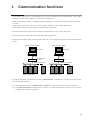
1.
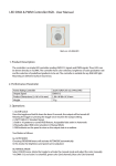
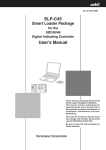
Communication functions
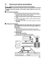
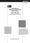
• In the RS-485 system, up to 31 instruments (see *1) can be connected with one master station. The “station
addresses” are then used to identify mate stations for communication.
• When the following procedure is completed during communication, various data for the instrument can be read
or written:
(1)The master station (host computer) transmits a request message to a slave station (instrument).
(2)The master station receives a response message from the slave station.
• Instructions from master station to slave station are classified into two types; “read” and “write”.
• The type of ready/write data can be optionally selected by “data address”.
• CPL(Control Peripheral Link) communications network is the Yamatake Corporation's host-communications
system.
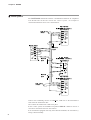
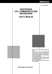
RS-485 connection example
RS-485 connection example
Master station
RS-232C
RS-232C
RS-232C/RS-485
converter
RS-485 (5-wire system)
Connection between master
station and slave station
Master station
Slave
station
CMC10L001A000 (*2)
RS-485 (3-wire system)
Connection between master
station and slave station
Slave
station
• The high-performance communication controller CMC410A102 is available for conversion between the RS232C and RS-485 interfaces.
(*1) When the master station is an MA500 DIM or CMC410, it can be connected to up to 16 slave stations.
(*2) The CMC10L001A000 communication controller is an RS-232C/RS-485 (3-wires type) converter
available from Yamatake Corporation.
1-1
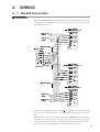
2.
WIRING
2 - 1 RS-485 Connection
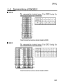
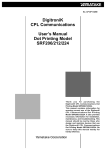
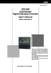
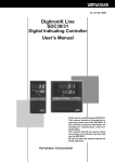
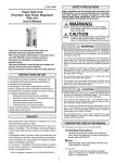
■ 5-wire system
When the DIGITRONIK instruments with the communication functions in
compliance with the RS-485 are used in the 5-wires system, they are connected,
for example, as follows:
! "
#$
%
! "
#$
%
! "
#$
%
Connect two terminating resistors of 150Ω 5%, 1/2W min. to the instrument at
each end of the transmission line. Also connect the shield wires to FG at one
place.
In the 5-wires system, the Yamatake Corporation CMC10L can be used as a
converter in the master station. It can also be used as a converter in the slave
station when the number of the slave stations is only one, but cannot be used as a
converter in a slave station when two or more slave stations are used.
2-1
Chapter 2. WIRING
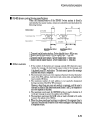
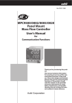
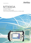
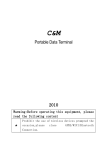
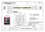
■ 3-wire system
The DIGITRONIK instruments with the communication functions in compliance
with the RS-485 can also be used in the 3-wires system. An example of
connection methods in such a case is shown below.
!" #
$% &
'
!" #
$% &
!" #
$% &
Connect one terminating resistor of 150Ω 5%, 1/2W min. to the instrument at
each end of the transmission line.
Also connect the shield wires to FG at one place.
In the 3-wires system, the Yamatake Corporation CMC10L cannot be used as a
converter in the master station or slave station.
In an instrument equipped with only three RS-485 terminals, the asterisked (*)
wiring is done internally.
2-2
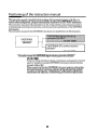
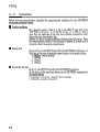
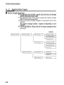
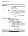
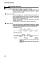
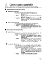
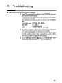
6.
Communication for master station
6-1
Precautions for programming
• The longest response time of the instrument is 2sec.
Therefore, the response monitor time should be set to 2sec.
• If no response is obtained within 2sec, retransmit the same message. When no response remains coming even
after making retransmission twice, it should be regarded as a communication error.
• The above-mentioned retransmission is required since a message may not be properly transmitted due to
noise or the like during communication.
Note
When the device distinction codes "X" and "x" are used alternately during
message retransmission from the master station, the received response message
can be conveniently identified to be the latest message or preceding one.
6-1
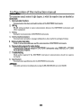
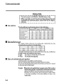
6. Communication program for master station
6-2
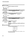
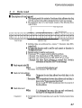
Examples of communication program
The program examples given in this paragraph are written in FUJITSU F-BASIC Ver.6.0 for Windows95/98/NT.
This program is shown as a reference for making a program.
■ Before executing the program
Check the instrument communication conditions, and station address.
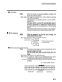
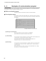
■ Executing the program
This program is used for data read and data write. When the program is executed,
the application layers of the request message and response message communicated
are indicated.
RS, 123W, 4
Application layer in response message
00, 10, - 20, 0, 40
Application layer in request message
WS, 234W, 1, 1
Application layer in response message
00
Example of indication of execution result
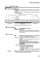
● Setting for communication
Set the station address of a mate instrument to "ADDRESS".
Open the RS-232C and call the subroutine *INIT. DATA.
●
Data reading
After setting the read start data address to "READ. ADRS" and the read data count
to "READ. LEN", call the subroutine *DATA. READ.
This program permits four data to be read from the data address 123.
Change the setting so as to meet the instrument used.
● Data writing
After setting the write start data address to "WRITE. ADRS", the write data count
to "WRITE. LEN", and the write data to "WRITE. DATA", call the subroutine
*DATA. WRITE.
This program permits two data to be written from the data address 234. Change
the setting so as to meet the instrument used.
6-2
6. Communication program for master station
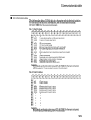
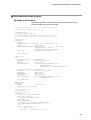
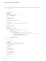
■ Data read/write sample program
Handling Precautions
Yamatake Corporation won't be absolutely responsible for any trouble
caused by applying this program sample.
'****************************************************************
'* Data Read Write Sample Program (Ver.1.00)
*
'*
*
'* OS:Windows 95/98
*
'* Language: Fujitsu F-BASIC V6.0
*
'* All rights reserved. Copyright(C) 1999, Yamatake Corporation *
'****************************************************************
'
'Initilize data
*INITIALIZE
DEFLNG A - Z
dim READ_DATA( 100 ), WRITE_DATA( 100 ) 'Read/write data area
ADDRESS = 1
'Device address
OPEN "COM0:(S8E1N8NN,SD200,RB4096)" AS #1
'Open RS-232C
'(8bit,Even parity,1 stop bit)
'(8bit,No Parity,2stop bit"S8N2N8NN")
baud 0,9600
'Transmission Speed(9600bps)
GOSUB *INIT_DATA
'
' Main routine
*MAIN
'Reading 4 data from the data address 123
READ_ADRS = 123
'Read start data address
READ_LEN =
4
'Read count
GOSUB *DATA_READ
'<Output>COM_ERROR:Communication error
'
RESPONSE:End code
'
READ_DATA(i)(i=0 to READ_LEN-1):Read data
'
'Writing 4 data from the data address 234
WRITE_ADRS = 234
'Write start data address
WRITE_LEN =
2
'Write count
WRITE_DATA(0) = 1
'Write data No.1
WRITE_DATA(1) = 1
'Write data No.2
gosub *DATA_WRITE
'<Output>COM_ERROR:Communication error
'
RESPONSE:End code
goto *PROCESS_END
'
'Ending routine
*PROCESS_END
CLOSE #1
'Close RS-232C
INPUT "Press any key", x$:END
'
'**********************
'* Read Subroutine
*
'**********************
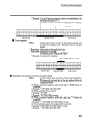
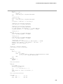
*DATA_READ
A = READ_ADRS: gosub *BIN_TO_ASCII
CMD$ = "RS," + A$ + "W,"
A = READ_LEN: gosub *BIN_TO_ASCII
CMD$ = cmd$ + A$
GOSUB *COMMUNICATION
IF COM_ERROR <> 0 OR RESPONSE <> 0 THEN RETURN
A$ = RIGHT$( RECEIVE$, LEN( RECEIVE$ ) - 3 ) + ","
J1 = 1
FOR I = 0 TO READ_LEN - 1
J2 = INSTR( J1, A$, "," )
READ_DATA( I ) = VAL( MID$( A$, J1, J2 - J1 ) )
6-3
6. Communication program for master station
J1 = J2 + 1
NEXT
RETURN
'
'**********************
'* Write Subroutine *
'**********************
*DATA_WRITE
A = WRITE_ADRS: GOSUB *BIN_TO_ASCII
CMD$ = "WS," + A$ + "W"
FOR I = 0 TO WRITE_LEN - 1
A = WRITE_DATA( I ): GOSUB *BIN_TO_ASCII
CMD$ = CMD$ + "," + A$
NEXT
GOSUB *COMMUNICATION
RETURN
'
'ASCII character conversion subroutine
'
*BIN_TO_ASCII
A$ = STR$( A )
IF LEFT$( A$, 1 ) = " " THEN A$ = RIGHT$( A$, LEN( A$ ) - 1 )
RETURN
'
'****************************
'* Communication Subroutine *
'****************************
*COMMUNICATION
COM_RETRY = 3: COM_ERROR = -1
WHILE ( COM_RETRY > 0 AND COM_ERROR <> 0 )
COM_ERROR = 0
'
WHILE ( eof( 1 )=0 ): A$ = INPUT$( 1, #1 ): WEND '
GOSUB *SEND_COMMAND
'
PRINT "Application layer in response message": PRINT CMD$
GOSUB *RECEIVE_COMMAND
'
IF COM_ERROR=0 THEN PRINT "Application layer in response message": PRINT RECEIVE$
IF COM_ERROR=1 THEN PRINT "Time out error"
IF COM_ERROR=2 THEN PRINT "Check sum error"
IF COM_ERROR<0 THEN PRINT "Data link layer error"
PRINT
COM_RETRY = COM_RETRY - 1
WEND
RETURN
'
'********************
'* Send Subroutine *
'********************
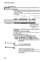
*SEND_COMMAND
A$ = RIGHT$( "0" + HEX$( ADDRESS ), 2 )
A$ = STX$ + A$ + SUB_ADR$ + DEVICE$ + CMD$ + ETX$
GOSUB *MAKE_SUM
SEND$ = A$ + SUM$ + CR$ + LF$
PRINT #1, SEND$;
RETURN
'
'**********************
'* Recive Subroutine *
'**********************
'COM_ERROR:
' = 0: Normal
' = 1: Time out error
' = 2: Check sum error
' < 0: Data link layer error
'
*RECEIVE_COMMAND
'
'Waiting for STX
6-4
6. Communication program for master station
A$ = ""
WHILE ( A$ <> STX$ )
RECEIVE$ = ""
GOSUB *RECV_SUB: IF COM_ERROR THEN RETURN
WEND
'
'Waiting for ETX
WHILE ( A$ <> ETX$ )
GOSUB *RECV_SUB: IF COM_ERROR THEN RETURN
WEND
IF SUM_FLAG = 0 THEN SUM$ = "": GOTO *RECV_CR
'
'Waiting for 1'st character in check sum
GOSUB *RECV_SUB: IF COM_ERROR THEN RETURN
'
'Waiting for 2'nd character in check sum
GOSUB *RECV_SUB: IF COM_ERROR THEN RETURN
A$ = LEFT$( RECEIVE$, LEN( RECEIVE$ ) - 2 ): GOSUB *MAKE_SUM
IF RIGHT$( RECEIVE$, 2 ) <> SUM$ THEN COM_ERROR = 2: RETURN
'
'Waiting for CR
*RECV_CR
GOSUB *RECV_SUB: IF COM_ERROR THEN RETURN
IF A$ <> CR$ THEN COM_ERROR = -2: RETURN
'
'Waiting for LF
GOSUB *RECV_SUB: IF COM_ERROR THEN RETURN
IF A$ <> LF$ THEN COM_ERROR = -3: RETURN
'
'Checking data link layer
IF MID$(SEND$,2,5) <> MID$(RECEIVE$,2,5) THEN COM_ERROR = -1: RETURN
RECEIVE$ = MID$( RECEIVE$, 7, LEN( RECEIVE$ ) - LEN( SUM$ ) - 9 )
RESPONSE = VAL( LEFT$( RECEIVE$, 2 ) )
RETURN
'
'Waiting for 1 character subroutine
'(Same routine as time out monitoring)
'
*RECV_SUB
A = 0
WHILE ( 1 )
A$ = TIME$
WHILE ( A$ = TIME$ )
IF EOF(1)=0 THEN A$ = INPUT$(1,#1): RECEIVE$=RECEIVE$+A$: RETURN
A = A + 1: IF A = TIME_CNT THEN *RECV_ERR
WEND
WEND
*RECV_ERR
COM_ERROR = 1
RETURN
'
'Check sum subroutine
'
*MAKE_SUM
A = 0: SUM$ = ""
IF SUM_FLAG = 0 THEN RETURN
FOR I = 1 TO LEN( A$ )
A = A + ASC( MID$( A$, I, 1 ) )
NEXT
SUM$ = RIGHT$( "0" + HEX$( (-A) AND &HFF ), 2 )
RETURN
'
'Data initializeing subroutine
'
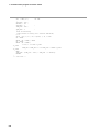
*INIT_DATA
STX$ = CHR$( 2 )
'STX code
ETX$ = CHR$( 3 )
'ETX code
6-5
6. Communication program for master station
CR$ = CHR$( 13 )
'CR code
LF$ = CHR$( 10 )
'LF code
'
SUB_ADR$ = "00" '
DEVICE$ = "X" '
SUM_FLAG = 1
'
TIME_OUT = 2000 '
TIME_CNT = 0
'
'
'Time out monitoring
'(Same routine as waiting for 1 charcter subroutine)
A = 0
while ( eof( 1 )=0 ): A$ = input$( 1, #1 ): wend
A$ = TIME$
WHILE ( A$ = TIME$ ): WEND
A$ = TIME$
WHILE ( A$ = TIME$ )
if eof( 1 )=0 then *I_LOOP1
*I_LOOP1
TIME_CNT = TIME_CNT + 1: IF TIME_CNT = A THEN *I_LOOP2
*I_LOOP2
WEND
TIME_CNT = (TIME_OUT / 1000!) * TIME_CNT + 1 'Round up
RETURN
'
'--- Last Line ---
6-6
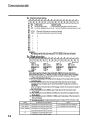
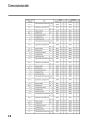
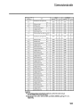
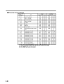
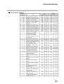
Appendix
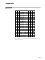
■ Code Table
Upper
Bits
Lower
Bits
0
1
2
3
4
5
6
0
SPACE
0
@
P
1
!
1
A
Q
a
q
`
7
p
2
STX
"
2
B
R
b
r
3
ETX
#
3
C
S
c
s
4
$
4
D
T
d
t
5
%
5
E
U
e
u
6
&
6
F
V
f
v
7
'
7
G
W
g
w
8
(
8
H
X
h
x
9
)
9
I
Y
i
y
*
:
J
Z
j
z
B
+
;
K
[
k
{
C
,
<
L
¥
l
—
=
M
]
m
}
E
.
>
N
^
n
~
F
/
?
O
_
o
A
D
LF
CR
The shaded areas (
) are not used by this communication system. (The codes
depend on the station.)
Appendix-1
Appendix
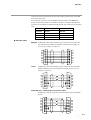
■ Connection with CMC10L
The CMC10L001A000 is available as an RS-232C/RS-485 (3-wire system) converter from Yamatake Corporation. The following diagram shows an example of
wiring using a straight cable for a host computer in the terminal mode:
*,- .
//
#0/1 !
23 4
%
%
&
&
'
(
'
(
)
*
)
"
+
+
!
#$
"
$
#$
"
$
&,- .
//
#0/1 !
23 4
*
*,- .
//
#0/1 !
23 4
Connect two terminating resistors of 150Ω±5%, 1/2W min. to the instrument at
each end of the transmission line.
Conduct the wiring externally for the wires marked with an asterisk.
Appendix-2
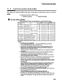
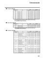
Appendix
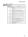
Connect the master station SD to the slave station RD, and the master station RD
to the slave station SD.
To execute this connection, set the MODE switch provided in the CMC10L as
shown in the following table in accordance with the host computer side RS-232C
connector pin arrangement (modem/terminal) and the type of cable (cross/straight)
used:
RS-232C
Cable type
MODE switch
TERMINAL
Straight
MODEM
TERMINAL
Cross
TERMINAL
MODEM
Straight
TERMINAL
MODEM
Cross
MODEM
● RS-232C cable
Straight: An RS-232C cable with a D-Sub (9-pin) connector at each end where
pins with the same number are mutually connected (for example, pin
(2) to pin (2), and pin (3) to pin (3))
CD
SD
RD
ER
SG
DR
RS
CS
Cross:
1
2
3
4
5
6
7
8
1
2
3
4
5
6
7
8
CD
SD
RD
ER
SG
DR
RS
CS
An RS-232C cable with a D-Sub (9-pin) connector at each end where
different number pins are connected (for example, pin (2) to pin (3),
and pin (3) to pin (2))
SD
RD
RS
CS
DR
ER
CD
SG
2
3
7
8
6
4
1
5
2
3
7
8
6
4
1
5
SD
RD
RS
CS
DR
ER
CD
SG
D-Sub (25-pin) – D-Sub (9-pin) conversion cable:
An RS-232C cable for conversion between D-Sub (25-pin) and D-Sub
(9-pin)
FG
SD
RD
RS
CS
DR
ER
CD
SG
1
2
3
4
5
6
20
8
7
3
2
7
8
6
4
1
5
SD
RD
RS
CS
DR
ER
CD
SG
Appendix-3
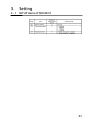
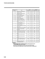
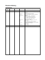
Revision History
Printed
Date
Manual Number
Edition
Revised pages
94-10
01-11
CP-UM-1589E 1st Edition
2nd Edition i,5-2
1-1,2-1,2-2
2-1,2-2,
Appendix1 to 3
4-2
4-4
5-3
5-5 to 5-12
5-12
5-6
01-12
3rd Edition
6-1 to 6-5
6-6
Appendix4
1-1
Description
Data write Count (EEPROM) 10,000 changed to
100,000.
CMA50 changed to CMC10L .
RS-232C and RS-485 connection diagrams
changed.
Check sum 35H 5 corrected to A.
Example of check sum corrected.
(1) 7BH to 76H, (2) 85H to 8AH,
(3) "85" to "8A", 35H to 41H
(Notes)Item5 revised.
Page 5-4 to 5-11 changed to 5-5 to 5-12
Page added.
No.3 Control action status corrected.
(5)OPEN to CLOSE, (6)CLOSE to OPEN
Sample program changed.
Page added.
Page deleted.
Connection example corrected.(RS-232C deleted)
Specifications are subject to change without notice.
Control Products Division
Sales contact: Yamatake Corporation,
IBD Sensing and Control Department
Totate International Building
2-12-19 Shibuya Shibuya-ku Tokyo 150-8316 Japan
Phone: 81-3-3486-2380
Fax:
81-3-3486-2300
This has been printed on recycled paper.
Printed in Japan.
1st Edition: Issued in June, 1994
3rd Edition: Issued in Dec., 2001(R)