1
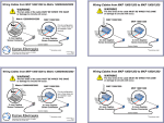
MBC15081
Bipolar Microstep Driver
User’s Guide
A N A H E I M
A U T O M A T I O N
910 East Orangefair Lane, Anaheim, CA 92801
e-mail: [email protected]
L010133
(714) 992-6990 fax: (714) 992-0471
website: www.anaheimautomation.com
January 2013
MBC15081 Features
• 1.5 Amps/Phase Output Current
• Bipolar Microstepping Driver Operation
• Over Temperature and Short Circuit Shutdown
• Microstep Divisors of 8, 4, 2, or Full Step
• Compact Package: 2.00” x 1.75” x 0.60”
• 12-24VDC Power Requirement
• Accepts TTL Logic or 24V Level Inputs
• Ideal for Precise Positioning
• Efficient and Durable
• Long Life Expectancy
General Description
The MBC15081 is a 1.5 amps/phase bipolar microstep driver capable of running four, six, and eight lead
step motors. The MBC15081 has an output current range of 0.5 to 1.5 amps/phase and operates off
12VDC minimum to 24VDC maximum. The inputs are capable of running from either open collector or
TTL level logic outputs, or sourcing 24VDC outputs from PLCs. The MBC15081 features resolutions from
200 - 1600 steps/revolution, providing smooth rotary operation. The MBC15081 features include built in
over temperature and short circuit shut down, automatic 70% reduction in current after clock pulses step
being received, and status LED’s to indicate power on (green LED) and clocks being received (yellow
LED). The MBC15081 is a compact, low profile package meant to be used where space is limited but
performance is expected.
Dimensions
Ordering Information
Part Number
L010133
Description
MBC15081
12-24VDC, 0.3-1.5A Bipolar Microstep Driver, Open Frame
MBC25081
12-24VDC, 0.5-2.5A Bipolar Microstep Driver, Packaged with Heat Sink
CBL-AA4031
7 Pin Input Connector with 12”, 22AWG Leads
CBL-AA033
4 Pin Motor Connector with 12”, 22AWG Leads
PSAM24V2.7A
24V @ 2.7A Universal Input Power Supply
CON-6404407
7 Pin Connector with 0.100” Centers (Amp #640440-7)
CON-6404404
4 Pin Connector with 0.100” Centers (Amp #640440-4)
January 2013
Wiring Diagrams
Input Pin Descriptions
Input Pin Descriptions
Pin #
Description
CBL-AA4031
Wire Color
Pin #
Description
CBL-AA4033
Wire Color
1
Direction
Brown
1
Phase A
Brown
2
Clock
Red
2
Phase Ā
Red
3
On/Off
Orange
3
Phase B
Orange
4
MS2
Yellow
4
Phase B
Yellow
5
MS1
Green
6
12VDC-24VDC
Blue
7
0VDC (Gnd)
Violet
Direction:
Clock:
On/Off:
Microstep Resolution Truth Table
MS1
MS2
Resolution
Active
Active
Full Step
Inactive (Open)
Active
Half Step
Active
Inactive (Open)
Quarter Step
Inactive (Open)
Inactive (Open)
Eighth Step
Logic “1” CW
Logic “0” CCW
Active - 1 Step
Inactive (open) - Reduce Current Mode
Active - Off
Inactive (open) - On
Notes:
Opens Inputs are inactive and internally pulled up to
+5VDC for JP1 position 1-2 (Sinking)
Open Inputs are inactive and internally pulled down
to 0VDC for JP1 position 2-3 (sourcing)
A. Minimum Command Active Time Before Clock
Pulse (Data Set-Up Time)...200nS
B. Minimum Command Active Time After Clock Pulse
(Data Hold Time).....200nS
C. Minimum Clock Pulse Width.......................1.0uS
D. Minimum Clock Inactive Time....................1.0uS
Maximum Clock Frequency...........................500kHz
With JP1 in position 1-2 (sinking) the inputs are considered inactive of Logic “1” if left open, or active or
Logic “0” if grounded. With JP1 in position 2-3 (sourcing) the inputs are considered inactive or Logic “0”
if left open, and active or Logic “1” if pulled to 3.5 - 24VDC.
L010133
January 2013
Step Motor Configurations
The output current on the MBC15081 is set by the onboard potentiometer. This potentiometer determines
the per phase peak output current of the driver. The relationship between the output current and the potentiometer value is as follows:
WARNING! Step motors will run hot even when configured correctly. Damage may occur to the motor if
a higher than specified current is used. Most specified motor currents are maximum values. Care should
be taken to not exceed these ratings.
MBC15081 Potentiometer Settings
Peak Potentiometer
Current
Setting
Peak
Current
Potentiometer
Setting
0.30A
0%
1.02A
60%
0.42A
10%
1.14A
70%
0.54A
20%
1.26A
80%
0.66A
30%
1.38A
90%
0.78A
40%
1.50A
100%
0.90A
50%
--
--
Reducing Output Current
Reducing the output current is accomplished automatically and occurs approximately 20mSec after the
last of the clock input has been received. The amount of current per phase in the reduction mode is approximately 70% of the set current. When the current reduction circuit is activated, the current reduction
resistor is paralleled with the current adjustment potentiometer. This lowers the total resistance value,
and thus lowers the per phase output current.
Connecting the Step Motor
Phase 1 and Phase 3 of the step motor are connected to pins 1 and 2 on connector P2. Phase 2 and
Phase 4 of the step motor are connected to pins 3 and 4 on connector P2. Please refer to the figure for
a typical APPLICATION HOOK-UP.
Note: the physical direction of the motor with respect to the direction input will depend on the connection
of the motor windings. To reverse the direction of the motor with respect to the direction input, switch the
wires on Phase 1 and Phase 3.
WARNING: DO NOT CONNECT OR DISCONNECT MOTOR WIRES WHILE POWER IS APPLIED!
Motor Selection
The MBC15081 is a Bipolar Microstep Driver that is compatible with both Bipolar and Unipolar Motor
Configurations, (i.e. 8 and 4 lead motors, and 6 lead center tapped motors).
Step motors with low current ratings and high inductance will perform better at low speeds, providing
higher low-end torque. Motors with high current ratings and low inductance will perform better at higher
speeds, providing more high-end torque.
Since the MBC15081 uses a constant current source drive technique, it is not necessary to use a motor
that is rated at the same voltage as the supply voltage. What is important is that the potentiometer is set
to the appropriate current level based on the motor being used. Higher voltages will cause the current to
flow faster through the motor coils. This in turn means higher step rates can be achieved. Care should
be taken not exceed the maximum voltage of the driver.
L010133
January 2013
Step Motor Configurations
Step motors can be configured as 4, 6 or 8 leads. Each configuration requires different currents. Refer
to the lead configurations and the procedures to determine their output current.
Determining Output Current
The Output current for a motor used with a bipolar driver is determined differently from that of a unipolar
driver. In the MBC15081, a sine/cosine output function is used in rotating the motor. The output current
for a given motor is determined by the motors current rating and the wiring configuration of the motor.
There is a current adjustment potentiometer used to set the output current of the MBC15081. This sets the
peak output current of the sine/cosine waves. The specified motor current (which is the unipolar value) is
multiplied by a factor of 1.0, 1.4, or 2.0 depending on the motor configuration (series, half-coil, or parallel).
6 Lead Motors
Half-Coil Connection: When configuring a 6 lead motor in half-coil (connected from one end of the coil
to the center tap), multiply the specified per Phase (or unipolar) current rating by 1.4 to determine the
current setting potentiometer value. This configuration will provide more torque at higher speeds when
compared to the series configuration.
Series: When configuring the motor is series (connected from end to end with the center tap floating) use
the specified per Phase (or unipolar) current rating to determine the current setting potentiometer value.
8 Lead Motors
Series Connection: When configuring the motor windings in series, use the per Phase (or unipolar) current rating to determine the current setting potentiometer value.
Parallel Connection: When configuring the motor windings in parallel, multiply the per Phase (or unipolar)
current rating by 2.0 to determine the current setting potentiometer value.
4 Lead Motors
Series Connection: Multiply the specified series motor current by 1.4 to determine the current adjustment
potentiometer value. Four Lead Motors are usually rated with their appropriate series current, as opposed
to the Phase Current, which is the rating for 6 and 8 lead motors.
L010133
January 2013
Connecting to the MBC15081
The MBC15081 is designed with cost savings and size as two of the primary design criteria. For this reason,
the MTA-100 series connector was chosen for these products as a reliable small and low cost connector.
This is a common Insulation Displacement Connector (IDC) manufactured by AMP Corporation. The
inputs to the driver are on a 7-pin connector and the motors are on a 4-pin connector. These connectors
are not supplied with the driver, but can be purchased from Anaheim Automation or AMP/Tyco Electronics.
These two images show how a hand tool can be used to quickly make the cable to connect to the driver.
This cable can be made in approximately 10 seconds per wire using the hand tool.
Tooling from AMP/Tyco Electronics
Part Number
Description
58074-1
Manual Hand Tool with Interchangeable Head (shown above)
58075-1
Air Hand Tool with Interchangeable Head
58338-1
Air Bench Mount Tool with Interchangeable Head and Foot Switch
58246-1
Die Head for Closed End MTA-100 Connectors (shown above)
Connectors from AMP/Tyco Electronics
L010133
Part Number
Description
640440-7
7 Pin MTA-100 Connector, Closed End with Lock, 22 AWG Red, Tin Plated
640440-4
4 Pin MTA-100 Connector, Closed End with Lock, 22 AWG Red, Tin Plated
640441-7
7 Pin MTA-100 Connector, Closed End with Lock, 24 AWG White, Tin Plate
640441-4
4 Pin MTA-100 Connector, Closed End with Lock, 24 AWG White, Tin Plated
640440-7
7 Pin MTA-100 Connector, Closed End with Lock, 26 AWG Blue, Tin Plated
640442-4
4 Pin MTA-100 Connector, Closed End with Lock, 26 AWG Blue, Tin Plated
January 2013
COPYRIGHT
Copyright 2013 by Anaheim Automation. All rights reserved. No part of this publication may be reproduced,
transmitted, transcribed, stored in a retrieval system, or translated into any language, in any form or by
any means, electronic, mechanical, magnetic, optical, chemical, manual, or otherwise, without the prior
written permission of Anaheim Automation, 910 E. Orangefair Lane, Anaheim, CA 92801.
DISCLAIMER
Though every effort has been made to supply complete and accurate information in this manual, the
contents are subject to change without notice or obligation to inform the buyer. In no event will Anaheim
Automation be liable for direct, indirect, special, incidental, or consequential damages arising out
of the use or inability to use the product or documentation.
Anaheim Automation’s general policy does not recommend the use of its’ products in life support applications
wherein a failure or malfunction of the product may directly threaten life or injury. Per Anaheim Automation’s
Terms and Conditions, the user of Anaheim Automation products in life support applications assumes all
risks of such use and indemnifies Anaheim Automation against all damages.
LIMITED WARRANTY
All Anaheim Automation products are warranted against defects in workmanship, materials and construction,
when used under Normal Operating Conditions and when used in accordance with specifications. This
warranty shall be in effect for a period of twelve months from the date of purchase or eighteen months
from the date of manufacture, whichever comes first. Warranty provisions may be voided if products
are subjected to physical modifications, damage, abuse, or misuse.
Anaheim Automation will repair or replace at its’ option, any product which has been found to be defective
and is within the warranty period, provided that the item is shipped freight prepaid, with previous authorization
(RMA#) to Anaheim Automation’s plant in Anaheim, California.
TECHNICAL SUPPORT
If you should require technical support or if you have problems using any of the equipment covered by this
manual, please read the manual completely to see if it will answer the questions you have. If you need
assistance beyond what this manual can provide, contact your Local Distributor where you purchased the
unit, or contact the factory direct.
ANAHEIM AUTOMATION
L010133
January 2013