1
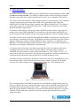
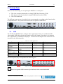
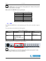
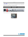
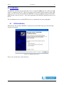
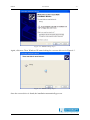
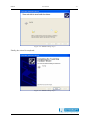
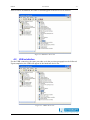
Radar Interface Module RIM782 User manual Edition Edition Date Status : : : 4 02/09/13 Released Issue DOCUMENT IDENTIFICATION SHEET DOCUMENT DESCRIPTION Document Title Radar Interface Module RIM782 User Manual 3 EDITION : Document Reference Number 13/10/09 EDITION DATE : Abstract This document describes how you should connect the RIM782 and how it should be installed on your computer. Radar Interface Module ARP CONTACT PERSON : Keywords UVR UDR GPS BERT SAUVILLER ACP TEL : +32 14 231811 : DOCUMENT STATUS AND TYPE STATUS Working Draft Draft Proposed Issue Released Issue ; CATEGORY Executive Task Specialist Task Lower Layer Task ; ELECTRONIC REARUP IE-UM-00034-003 RIM782.doc INTERNAL REFERENCE NAME : HOST SYSTEM MEDIA SOFTWARE(S) WINDOWS XP Type : Hard disk Word XP Media Identification : RIM782 User Manual -3- DOCUMENT APPROVAL The following table identifies all authorities who have successively approved the present issue of this document. AUTHORITY NAME AND SIGNATURE DATE Author BERT SAUVILLER 15/06/07 Editor Peter Verhoeven 18/07/07 Director ATC Director Software Department Ing. M. Vanuytven Ir. E. Moons RIM782 User Manual -4- DOCUMENT CHANGE RECORD The following table records the complete history of the successive editions of the present document. REASON FOR CHANGE SECTIONS PAGES AFFECTED EDITION DATE 1.0 20/07/07 New document All 1.1 09/01/08 All 1.2 23/06/08 3 13/10/09 Chapter 2: added, same information as in the brochure Chapter 3: DB15 pin layout added Chapter 4: DHM view added Paragraph 3.1: Pin layout Differential ACP/ARP added Paragraph 3.2: Pin layout RASS connector added Filename changed 4 02/09/13 English language corrections 3.1 3.2 None P16-17 RIM782 User Manual -5- TABLE OF CONTENTS 1. INTRODUCTION.......................................................................................................................................8 2. PRODUCT SPECIFICATIONS ................................................................................................................9 2.1 2.2 2.3 2.4 2.5 2.6 3. VIDEO PROCESSING UNIT ...........................................................................................................................9 DATA PROCESSING UNIT ............................................................................................................................9 GENERAL SPECIFICATIONS ........................................................................................................................9 OPTIONAL ACCESSORIES ...........................................................................................................................9 SUPPORTED PROTOCOLS ..........................................................................................................................10 TECHNICAL SPECIFICATIONS ...................................................................................................................11 CONNECTIONS.......................................................................................................................................12 3.1 UVR .......................................................................................................................................................12 3.2 UDR .......................................................................................................................................................13 3.3 GPS ........................................................................................................................................................15 4. INSTALLATION ......................................................................................................................................16 4.1 UVR INSTALLATION ...............................................................................................................................16 4.2 UDR INSTALLATION ...............................................................................................................................19 4.3 CONTROL VIA THE DATA HANDLER MODULE .........................................................................................20 RIM782 User Manual -6- TABLE OF FIGURES Figure 1-1: RIM782 with TMD3 software on laptop..............................................................................................8 Figure 3-1: rear panel..........................................................................................................................................12 Figure 3-2: Rear panel - UVR ..............................................................................................................................12 Figure 3-3: Rear panel - UDR..............................................................................................................................13 Figure 3-4: Rear panel - GPS ..............................................................................................................................15 Figure 3-5: GPS 450 ............................................................................................................................................15 Figure 4-1: RIM782 startup step 1 .......................................................................................................................16 Figure 4-2: RIM782 startup step 2 .......................................................................................................................17 Figure 4-3: RIM782 startup step 3 .......................................................................................................................17 Figure 4-4: RIM782 startup step 4 .......................................................................................................................18 Figure 4-5: RIM782 startup step 5 .......................................................................................................................18 Figure 4-6: RIM782 in device list.........................................................................................................................19 Figure 4-7: UDR in device list .............................................................................................................................19 Figure 4-8: RIM782 in DHM ...............................................................................................................................20 TABLE OF TABLES Table 3-1: UVR connections.................................................................................................................................12 Table 3-2: Differential ACP/ARP Connector DB9 pin layout..............................................................................13 Table 3-3: UDR connections ................................................................................................................................13 Table 3-4: Serial data 1/2 DB15 pin layout .........................................................................................................14 Table 3-5: RASS Connector DB15HD pin layout.................................................................................................14 RIM782 User Manual -7- CONVENTIONS USED IN THIS MANUAL The following conventions are used in this manual: * Note: This icon to the left of bold italicized text denotes a note, which alerts you to important information. Caution: This icon to the left of bold italicized text denotes a caution, which alerts you to the possibility of data loss or a system crash. 0 Warning: This icon to the left of bold italicized text denotes a warning, which alerts you to the possibility of damage to you or your equipment RIM782 User Manual -8- 1. Introduction The Radar Interface Module (RIM782) can be divided in two parallel running systems: data recorder and video recorder. The RIM782 contains all the necessary hardware to digitize the radar video and/or data, and provide this data to the PC over a standard USB interface. The video recorder functionality of the hardware interface is performed by 6 video channels, 2 trigger signals and 2 rotation interfaces (ARP-ACP signals both single ended and differential). The RIM782 can sample 2 analog video inputs simultaneously. The digitized video will be sent over an USB connection to a PC (USB Video) and can be used in both RASS-R as RASS-S applications. For instance, the RASS-R software can extract ADS-B messages from the video signal or display video on the TMD3 and MRD3. For RASS-S on the other hand, the RIM782 can record all types of SSR or Mode S radar video signals using the sectorial recording software. The radar recorder has two bidirectional digital RS232/RS422 synchronous serial data ports for inputting or outputting serial data. The RIM782 can both record and replay data. If more than two channels are required, multiple RIM782s can be "stacked" (or combined with a RDR803). The additional inputs azimuth and time (GPS) make it a real radar evaluation tool. This allows for example evaluating the extraction delay. A vital part of the radar chain is the data processing unit, with at its output a data stream containing radar plots or tracks under a specific format. The most common format is ASTERIX, but some radars use other formats like RDIF, EC, SVE, Aircat, CD, etc... To analyze these data, they must first be recorded and converted into a uniform format that can be displayed and analyzed by dedicated RASS-S or RASS-R software tools. Generally the data is produced on serial lines, because they need to be transmitted to one or more remote centers. This serial link can be run using a number of protocols like HDLC, Lap-B or X25. Other formats use a unique protocol such as the 13-bit formatted CD. Figure 1-1: RIM782 with TMD3 software on laptop The recordings made by the RIM782 can then be converted into a suitable data format for further evaluation: this can be the RASS-S data format (.S4) or RASS-R input format (.D6) or another third party data format like SASS-C. Continuous monitoring is possible in the RASS-R Trackan module. Furthermore, since the full communication protocol is recorded together with the radar data, an analysis of the line quality and communication protocol syntax is possible. RIM782 User Manual -9- 2. Product specifications 2.1 Video processing unit The video processing unit has a USB-connection to the processing PC, and the following other specifications: 2 analog input channels I/Q Analog input voltage Sampling rate Resolution digitized output 2.2 BNC connector -2V…+2V 8MHz 12bit Data processing unit The RIM782 has 2 serial communication channels for active and passive recording. They can handle transmission speeds up to 128 Kb/s. Two electrical standards are supported: RS232 (single ended) and RS485 (differential). The serial data is fed to the recorder using a female DB15 connectors (alike X.21 connections) on the rear panel of the RIM782. The unit is supplied with 2 RS232 Probe modules for connection of the DB15 to DB25 standard RS232 connection. A whole range of synchronous protocols is supported and others can be programmed upon request. 2.3 General specifications Temperature Range – Operating Temperature Range - Non operating Relative Humidity Max. Operating Altitude 2.4 0...40 degC -30...+50 degC 10%...80% 3080 m Optional accessories APM 485: ACP/ARP Probe Module: Differential Rotational Information input. Note that single ended azimuth input is by default supported by the RIM782. GPS 450: Weather-proof GPS receiver for UTC time stamping of messages. RIM782 2.5 User Manual - 10 - Supported protocols The RIM782 can handle the following passive protocols (up to 128k): • • • • • • • • HDLC: Passive recording of HDLC bases protocols, including Lap-B and X25.3 Passive monitoring. (E.g. ASTERIX, RDIF) LINK 1: Passive recording of Military LINK 1 protocol SYNC 13: Passive recording of most bit protocols as implemented on US radars (CD1, CD2, ASR9, etc...) Aircat 500: passive recording of Thales specific protocol TVT2 military protocol EV760 protocol Output U-HDLC and bit protocols Bit Recording Protocols (9600 BAUD): o AIRCAT 500 o ALENIA o AUSTRO o BMIL o ERICSSON o EUROCONTROL o FPS 117 o HUGHES o SVE o TOSHIBA o CUSTOMER SPECIFIC RIM782 2.6 User Manual Technical specifications Digital interface: ARP/ACP for Azimuth: TTL, 10 kΩ (max 0.5 V input) GPS interface for time stamping: Dedicated interface to GPS450 Serial Inputs/outputs: RS 232 C Receivers (Compatible with RS232C standard) Input resistance 3 kΩ min, 5kΩ typ, 7 kΩ max Low threshold 1.2V typ, 0.8 min. High threshold 1.7V typ, 3.0 max. Impedance 5kΩ typ (+15V to -15V) RS 232 C Drivers (Compatible with RS232C standard) High Level Output +5V min, +15V Low Level Output -15V min, -5V max Short Circuit Current ±100 mA Power off Impedance 300Ω Slew Rate RL=3K, CL=50pF 30V/μs RS 485 Receivers (Compatible with RS485 standard) Input resistance common mode 15kΩ typ (-7 to +12V) Receiver sensitivity ±0,2Vtyp Common Mode Range -7.0V min, +7.0V max. RS 485 Drivers (Compatible with RS485 standard) Short Circuit Current 150 mA Transition Time 40 ns max. (10-90%) Output current 28 mA min (RL=54Ω) Power Supply Input Voltage: 90-264V Input Frequency: 47-63Hz Power 22Watt Dimensions: 19inch device, 1U Connections: 2 USB connectors to computer - 11 - RIM782 User Manual - 12 - 3. Connections Based on the functioning, we can split up the RIM782 in 3 main parts: • • • The video recorder functionality or simply USB Video Recorder (UVR) The data recorder functionality or simply USB Data Recorder (UDR) The GPS connection The different connectors are described in the next paragraphs, according to their functionality as explained above. The picture below shows the rear panel of the RIM782. Figure 3-1: rear panel 3.1 UVR The UVR in the RIM782 has 6 analogue video signal inputs. These are suitable for PSR video signals, SSR video signals and weather radar video signals. From these 6, 4 channels can be quantized for simultaneous display or 1 channel can be sampled. The connections are described in the following table: Table 3-1: UVR connections 1 Name CH1/2/3/4 Video I Video Q Video ACP1/2 ARP1/2 Differential ACP1/2 ARP1/2 Trigger 1/2 USB Video Specification Video input I/Q input Connector type 4x BNC 2x BNC Value -2V,+2V, 10kΩ -2V,+2V, 10kΩ Single ended ACP/ARP input Differential ACP/ARP input Trigger input USB Video 2x BNC TTL 2x DB-9 female TTL 2x BNC USB TTL USB2.0 On the rear panel, they correspond to the following part: Figure 3-2: Rear panel - UVR * 1 There is a separate USB connector for dedicated video stream bandwidth. The name corresponds to the label printed on the equipment. CH1/2/3/4 means CH1, CH2, CH3 and CH4. RIM782 User Manual - 13 - * The DHM software can only take the analog signal from 1 channel, and not from 2 channels as the hardware can sample. Differential ACP/ARP DB9 connector pin layout: Table 3-2: Differential ACP/ARP Connector DB9 pin layout Name NC (not connected) ACP + NC ACP NC ARP + NC ARP NC 3.2 DB9 female on case 1 2 3 4 5 6 7 8 9 UDR The UDR in the RIM782 has 2 serial synchronous ports. They can be used either as input or output. The connections are described in the following table: Table 3-3: UDR connections Name Serial data1/2 Specification Serial data 1/ 2 Connector type 2x DB15 female RASS Input: ModeS-Clock, Mod-S Data, trigger Output: ACP, ARP, event, trigger USB Data DB15HD female Value Synchronous serial input RS232/RS422 TTL USB USB2.0 USB Data On the rear panel, they correspond to the following part: Figure 3-3: Rear panel - UDR * Radar data passed over LAN (TCP, UDP) will be fed directly into the PC via the Ethernet adapter. (Without the need of the RIM782) RIM782 User Manual - 14 - * The DHM software that controls the RIM782, can only use Serial data 1 and 2 as input or output, but not mixed (not possible is Serial data 1 input and Serial data 2 output or vice versa). Serial data 1/2 DB15 connector pin layout: Table 3-4: Serial data 1/2 DB15 pin layout Name Gnd TxD+ TxDRxD+ RxDRxC+ RxCTrxC+ TrxCTxC+ TxC-10Volt +10Volt +5Volt (USB4.2V) DB15 female on case 1, 8 9 2 11 4 13 6 14 7 / / 12 5 15 RASS Connector DB15HD connector pin layout: Table 3-5: RASS Connector DB15HD pin layout Name RASS ARP (output) (red connector on Intersoft DB15HD male cable to 5xBNC) RASS ACP (output) (green connector on Intersoft DB15HD male cable to 5xBNC) RASS PPS (output) (blue connector on Intersoft DB15HD male cable to 5xBNC) Reserved for future use Reserved for future use GND GND GND +12V GND Reserved for future use RASS Mode-S data (input) RASS Trigger (output) (grey connector on Intersoft DB15HD male cable to 5xBNC) RASS Trigger (input) (Black connector on Intersoft DB15HD male cable to 5xBNC) RASS Mode-S Clock (input) DB15HD female on case 1 2 3 4 5 6 7 8 9 10 11 12 13 14 15 RIM782 3.3 User Manual - 15 - GPS Intersoft Electronics’ GPS450 can be connected to the RIM782 so that the recordings made will be UTC time stamped. There is one connector foreseen: Specification GPS Connector type RJ45 Figure 3-4: Rear panel - GPS The data is distributed to the UVR and the UDR. Figure 3-5: GPS 450 Value Intersoft proprietary RIM782 User Manual - 16 - 4. Installation The RIM782 will only start up when the power is connected and when one of the two USB cables is connected to the PC. (There is no power on/off switch) Upon insertion of the USB cable, you will see the power LED of the RIM782 on and you will hear a beep sound in the RIM782 and a tone on your PC. This is the beginning of the RIM782 installation process on the PC. The installation process of the RIM782 drivers is explained in the next paragraphs. 4.1 UVR installation When the PC detects that a RIM782 is connected over the USB video port, the following window will appear: Figure 4-1: RIM782 startup step 1 Select ‘No, not this time’ and click Next. RIM782 User Manual Figure 4-2: RIM782 startup step 2 Again, click next. Then, Windows XP starts looking for a correct driver as in Figure 4-3. Figure 4-3: RIM782 startup step 3 Once the correct driver is found, the installation automatically goes on. - 17 - RIM782 User Manual Figure 4-4: RIM782 startup step 4 Finally, the wizard is completed. Figure 4-5: RIM782 startup step 5 - 18 - RIM782 User Manual - 19 - After a correct installation, the RIM782 should appear in the device list as follows: Figure 4-6: RIM782 in device list 4.2 UDR installation For the UDR connection, the same procedure as in the previous paragraph can be followed. Upon completion, the UDR will appear in the hardware device list: Figure 4-7: UDR in device list RIM782 User Manual 4.3 - 20 - Control via the Data Handler Module Once the RIM782 is completely installed, it can be accessed via the Data Handler Module (DHM) of RASS-R. In the ‘Proprietary Input’ node, a name ‘TMD [sn] 2 ’ will be available, containing the following subsections: • • • UDR2 [sn]: UDR configured as input TMD [sn]= the UVR of the RIM782 ADSBOnRim [sn]= the UVR of the RIM782 setup to receive ADS-B. In the ‘Proprietary Output’ node, a name ‘TMD [sn]’ will be available, containing the following subsection: • UDR2 [sn]: UDR configured as output Further details can be found in the DHM user manual and tutorial. Figure 4-8: RIM782 in DHM 2 [sn] = [serial number] of the hardware


![550 (PDF/57,3Ko) [F]](http://vs1.manualzilla.com/store/data/006354024_1-cb13f59715cefaa4ca521396f0348c03-150x150.png)