1
Starting Manual
UDOO Starting manual (beta)
Version 0.4
Table of Content
1. Introduction ........................................................................................................................ 4 1.1. What's UDOO? ..................................................................................................................................................................... 4 1.2. UDOO goals ........................................................................................................................................................................... 4 1.3. Specifications ....................................................................................................................................................................... 4 1.3.1. GPIO features .................................................................................................................................................................... 4 1.3.2. UDOO Quad ........................................................................................................................................................................ 4 1.3.3. UDOO Dual ......................................................................................................................................................................... 5 1.3.4. UDOO Dual Basic ............................................................................................................................................................. 5 2. Creating a bootable Micro SD card from Image ................................................................... 7 2.1. Write the image on micro SD card Using Linux: ................................................................................................... 7 2.2. Write the image on micro SD card Using Mac OSX .............................................................................................. 8 2.3. Write the image on micro SD card Using Windows ............................................................................................ 9 2.4. Creating a bootable Micro SD card: The Hard Way .......................................................................................... 11 2.4.1. Download Binaries ...................................................................................................................................................... 11 2.4.2. Compiling the Kernel and the modules. ............................................................................................................. 11 2.4.3. Preparing the partitions on the SD card ........................................................................................................... 12 2.4.4. Copy the files on the SD card ................................................................................................................................... 13 2.4.5. Installing U-‐Boot .......................................................................................................................................................... 13 3. Internal Connections ......................................................................................................... 14 3.1. Introduction ...................................................................................................................................................................... 14 3.2. Cpu’s Connections .......................................................................................................................................................... 14 3.2.1. I.Mx6 Debug Serial ...................................................................................................................................................... 14 3.2.2. Shared UART serial ..................................................................................................................................................... 15 3.2.3. Shared USB OTG bus ................................................................................................................................................... 19 3.2.4. Android Accessory Mode ........................................................................................................................................... 19 3.2.5. USB Debug mode .......................................................................................................................................................... 19 3.2.6. Switching between modes ........................................................................................................................................ 21 3.3. Communication example over UART ..................................................................................................................... 21 4. How to program SAM3X microcontroller .......................................................................... 23 4.1. Download Arduino IDE ................................................................................................................................................ 23 4.2. Install Arduino IDE ........................................................................................................................................................ 23 4.2.1. Windows .......................................................................................................................................................................... 23 4.2.2. Linux 32 / 64 .................................................................................................................................................................. 24 4.2.3. OSX ..................................................................................................................................................................................... 24 4.3. Apply UDOO patch to Arduino IDE .......................................................................................................................... 24 4.3.1. Why we need this patch ............................................................................................................................................ 24 4.4. Alternative procedure .................................................................................................................................................. 25 5. Shared GPIOs Management .............................................................................................. 27 5.1. Introduction ...................................................................................................................................................................... 27 5.2. SAM3x GPI/Os management ...................................................................................................................................... 27 5.3. i.MX6 GPI/O Management ........................................................................................................................................... 28 5.4. GPIOs Warnings ............................................................................................................................................................... 29 6. i.Mx6 Pinmuxing ............................................................................................................... 31 http://www.udoo.org/
2 UDOO Starting manual (beta)
Version 0.4
6.1. Introduction ...................................................................................................................................................................... 31 6.2. Extra available functions on UDOO pinout .......................................................................................................... 32 6.3. Example .............................................................................................................................................................................. 33 7. Appendix .......................................................................................................................... 34 7.1. How to create a Virtual Machine Environment ................................................................................................. 34 7.1.2. Introduction ................................................................................................................................................................... 34 7.1.3. Setting up work environment ................................................................................................................................. 35 7.2. Establish serial debug connection with UDOO .................................................................................................. 38 7.2.1. Introduction ................................................................................................................................................................... 38 7.2.2. Drivers .............................................................................................................................................................................. 38 7.2.3. Windows .......................................................................................................................................................................... 38 7.2.4. Linux .................................................................................................................................................................................. 44 7.2.5. Mac OSX ........................................................................................................................................................................... 44 7.2.6. Final step ......................................................................................................................................................................... 46 http://www.udoo.org/
3 UDOO Starting manual (beta)
Version 0.4
1. Introduction
1.1. What's UDOO?
UDOO is a mini PC that can be used both with Android and Linux OS, with an
embedded Arduino-compatible board. It is a powerful prototyping board for
software development and design; it’ s easy to use and allows developing projects
with minimum knowledge of hardware. UDOO merges different computing worlds
together: each one has its proper strenght- and weak- points, but all of them are
useful in today's life for educational purposes as well as Do-It-Yourself (DIY) and
quick prototyping. UDOO is an open hardware, low-cost platform equipped with an
ARM i.MX6 Freescale processor, and an Arduino Due compatible section based on
ATMEL SAM3X ARM processor, all this available on the same board!
1.2. UDOO goals
●
●
●
●
●
Develop an innovative product for a growing market
Give a new vision to the educational framework, with the idea of training up a
new generation of engineers, designers and software developers skilled in
digital technology: physical computing, multi-media arts, interactive arts, IoT...
Give a boost to the DIY world
Offer a low cost embedded platform for interactive arts with powerful tools:
Processing, OpenCV, PureData, openFramework
Provide companies with a great tool for fast prototyping
1.3. Specifications
UDOO retail line up consists of three models, sharing most of the featuresand
different only for connectivity and i.MX6 processor used. All three models feature an
embedded Arduino compatible section based on Arduino Due schematic. UDOO’ s
size are 4.33 inch x 3.35 inch (11 cm x 8.5 cm).
Warning: The UDOO I/O pins are 3.3V compliant. Higher voltages (like 5V) would
damage the board.
1.3.1. GPIO features
Current version, UDOO rev. D, has these additional features:
● S/PDIF digital audio in & out through pin headers;
● I2S/AC97/SSI digital audio multiplexer through pin headers;
● FlexCAN (Flexible Controller Area Network) through pin headers, it is possible
to switch this function’ s management between i.MX6 processor and SAM3X8E
processor;
● External SD card support through pins header: plug an external controller for
an additional SD card slot or for an eMMC module.
1.3.2. UDOO Quad
●
Freescale i.MX6Quad, 4 x ARM® Cortex™-A9 core @ 1GHz with ARMv7A
instruction set
http://www.udoo.org/
4 UDOO Starting manual (beta)
●
●
●
●
●
●
●
●
●
●
●
●
●
●
Version 0.4
GPU Vivante GC 2000 for 3D + Vivante GC 355 for 2D (vector graphics) +
Vivante GC 320 for 2D (composition)
Atmel SAM3X8E ARM Cortex-M3 CPU (same as Arduino Due)
RAM DDR3 1GB
76 fully available GPIO with Arduino-compatible R3 1.0 pinout
HDMI and LVDS + Touch
2 Micro USB (1 OTG)
2 USB 2.0 type A and 1 USB 2.0 internal pin header (requires adapter cable)
Analog Audio and Mic jacks
CSI Camera Connection
on board Micro SD card reader (boot device)
Power Supply (6-15V) and External Battery connector
Ethernet RJ45 (10/100/1000 MBit)
WiFi Module
SATA connector with power header
1.3.3. UDOO Dual
●
●
●
●
●
●
●
●
●
●
●
●
●
●
●
Freescale i.MX6DualLite, 2x ARM® Cortex™-A9 core @ 1GHz with ARMv7A
instruction set
GPU Vivante GC 880 for 3D and 2D (vector graphics) + Vivante GC 320 for 2D
(composition)
Atmel SAM3X8E ARM Cortex-M3 CPU (same as Arduino Due)
RAM DDR3 1GB
76 fully available GPIO with Arduino-compatible R3 1.0 pinout
HDMI and LVDS + Touch
2 Micro USB (1 OTG)
2 USB 2.0 type A and 1 USB 2.0 internal pin header (requires adapter cable)
Analog Audio and Mic jacks
CSI Camera Connection
on board Micro SD card reader (boot device)
Power Supply (6-15V) and External Battery connector
Ethernet RJ45 (10/100/1000 MBit)
WiFi Module
SATA connector with power header
1.3.4. UDOO Dual Basic
●
●
●
●
●
●
Freescale i.MX6DualLite, 2x ARM® Cortex™-A9 core @ 1GHz with ARMv7A
instruction set
GPU Vivante GC 880 for 3D and 2D (vector graphics) + Vivante GC 320 for 2D
(composition)
Atmel SAM3X8E ARM Cortex-M3 CPU (same as Arduino Due)
RAM DDR3 1GB
76 fully available GPIO with Arduino-compatible R3 1.0 pinout
HDMI and LVDS + Touch
http://www.udoo.org/
5 UDOO Starting manual (beta)
●
●
●
●
●
●
Version 0.4
2 Micro USB (1 OTG)
2 USB 2.0 type A and 1 USB 2.0 internal pin header (requires adapter cable)
Analog Audio and Mic jacks
CSI Camera Connection
on board Micro SD card reader (boot device)
Power Supply (6-15V) and External Battery connector
http://www.udoo.org/
6 UDOO Starting manual (beta)
Version 0.4
2. Creating a bootable Micro SD card from
precompiled image
The following paragraphs will guide to in the creation of a bootable micro SD card
for UDOO board, starting from a precompiled image file containing the UDOO
Operating system, which runs using the i.MX6 processor. Without the O.S., it si
possible only to use UDOO like a normal Arduino Due (only SAM3X8E processor).
The procedure is quite easy: simply unzip the image and write it on the SD card
using the dd tool for UNIX/MAC users or Win32DiskImager for Windows users. It is
not possible to create a bootable SD card with drag and drop. Please consider that
the micro SD card size must be at least 8GB; higher capacity SD memory cards may
be used but only 8GB will be available at the end of the procedure.
1.
Download any SD images (Ubuntu or Yocto) from the image section of the
website http://www.udoo.org/downloads/.
2. Extract the .img file from the .zip file you downloaded into any folder (this
path will be referred to as <img_file_path> in the guide).
3. Follow the instructions below for the OS you use:
2.1. Write the image on micro SD card using Linux:
From the terminal run:
df -h
If the PC used has a slot for SD cards (SD to micro SD adapter needed), insert the
card. If not, insert the card into any SD card reader and then connect it to the PC.
Note: the microSD card must be formatted using FAT32 File System!
Run again:
df -h
The device that had not been listed before is the micro SD card just inserted.
The left column will show the device name assigned to the micro SD card. It will have
a name similar to “/dev/mmcblk0p1″ or “/dev/sdd1″. The last part of the name (“p1″
or “1″, respectively) is the partition number, but it is necessary to write on the whole
micro SD card, not only on one partition. Therefore, it is necessary to remove that
part from the name (for example “/dev/mmcblk0″ or “/dev/sdd”) in order to work
with the whole micro SD card.
If the micro SD card contains more than one partition, it is necessary to unmount all
of these partitions (using the correct name found previously, followed by the letters
and numbers identifying the partitions) using the command:
e.g. sudo umount /dev/sdd1
Now, write the image on the micro SD card with the command:
sudo dd bs=1M if=<img_file_path> of=/dev/<sd_name>
http://www.udoo.org/
7 UDOO Starting manual (beta)
Version 0.4
Please be sure that you replaced the argument of input file (if=<img_file_path>) with
the pathof the .img file, and that the device name specified in output file’ s argument
(of=/dev/<sd_name>) is correct. This is very important, since you could lose all data
on the hard drive of the Host PC if it is usedthe wrong device name. Please also be
sure that the device name is that of the whole micro SD card, as described above,
not just a partition. (e.g. sdd, not sdds1 or sddp1, or mmcblk0 not mmcblk0p1)
e.g. sudo dd bs=1M if=/home/<user_name>/Download/2013-5-28-udoo-ubuntu.img
of=/dev/sdd
Once dd completes, run the sync command as root or run sudo sync as a normal
user (this will ensure that the write cache is flushed and that it is safe to unmount
the micro SD card). Then run:
sudo umount /media/<sd_label>
The micro SD card is now ready to be used. Simply, insert it in UDOO’ s microSD
Card slot and boot the system.
2.2. Write the image on micro SD card using Mac OSX
From the terminal run
df -h
If the Mac has a slot for SD cards (SD to micro SD adapter needed), insert the card.
If not, insert the card into any SD card reader and then connect it to the Mac. Note:
the microSD card must be formatted usingFAT32 File System!
Run again
df -h
The device that had not been listed before is the microSD card just inserted.
The name shown will be that of the filesystem’ s partition, for example, /dev/disk3s1.
Now consider the raw device name for using the entire disk, by omitting the final “s1″
and replacing “disk” with “rdisk” (considering previous example, use rdisk3, not
disk3 nor rdisk3s1). This is very important, since it could result in the loss of all data
of the disk of the Mac used, when referring to the wrong device name. Since there
could be other SD with different drive names/numbers, like rdisk2 or rdisk4, etc.
check again the correct name of the microSD card by using the df -h command both
before & after the insertion of the microSD card into the Mac used.
e.g. /dev/disk3s1 => /dev/rdisk3
If the microSD card contains more partitions, unmount all of these partitions (use the
correct name found previously, followed by letters and numbers that identify the
partitions) with the command:
sudo diskutil unmount /dev/disk3s1
Now write the image on the microSD card using the command:
http://www.udoo.org/
8 UDOO Starting manual (beta)
Version 0.4
sudo dd bs=1m if=path_del_file_img of=/dev/<sd_name>
Please be sure that you replaced the argument of input file (if=<img_file_path>) with
the path to the .img file, and that the device name specified in output file’ s
argument (of=/dev/<sd_name>) is correct. This is very important, since it could
result in the loss of all data of the disk of the Mac used, when referring to the wrong
device name.). Please also be sure that the device name is that of the whole micro
SD card as described above, not just a partition (for example, rdisk3, not disk3s1).
e.g. sudo dd bs=1m if=/home/user_name/Download/2013-5-28-udoo-ubuntu.img of=/dev/rdisk3
Once dd completes, run the sync command as root or run sudo sync as a normal
user (this will ensure that the write cache is flushed and that it is safe to unmount
the micro SD card). Then run:
sudo diskutil eject /dev/rdisk3
The micro SD card is now ready to be used. Simply, insert it in UDOO’ s microSD
Card slot and boot the system.
2.3. Write the image on micro SD card using Windows
Download the Win32DiskImager software
Unzip it, now there will be a new folder called “win32diskimager-v0.7-binary”.
If the PC used has a slot for SD cards (SD to microSD adapter needed), simply insert
the card. If not, insert the card into any SD card reader and then connect it to the PC.
Note: the microSD card must be formatted using FAT32 File System!
Run the file named Win32DiskImager.exe(with Windows Vista, 7 and 8 right-click the
file and select “Run as administrator”).
If the micro SD card (Device) used is not detected automatically, click on the drop
down box on the right and select the identifier of the micro SD card that has been
plugged in (e.g. [H:\]). Note: the microSD card must be formatted using FAT32 File
System!
Please be careful to select the correct drive identifier; if you use the wrong identifier,
you can lose all data on the PC's hard disk!
In the Image File box, choose the downloaded .img file and click “Write”. Note: click
YES in case it pops up a warning message.
The microSD card is now ready to be used. Simply insert it in UDOO’ s microSD Card
slot and boot the system.
http://www.udoo.org/
9 UDOO Starting manual (beta)
Version 0.4
http://www.udoo.org/
10 UDOO Starting manual (beta)
Version 0.4
2.4. Creating a bootable microSD card: The Hard Way
Note: The following instructions are referred to a Linux system.
A bootable SD card has 3 different elements:
● Kernel
● U-Boot (Universal Bootloader)
● File System (e.g: Ubuntu Linaro, Yocto)
A possible way to create a bootable SD card consists in installing these elements
separately from the binaries available on UDOO’ s website.
Alternatively, it is possible to compile the source code in order to get the binaries.
This is especially useful for people that want to customize and improve the UDOO
environment and getting the newest kernel/u-boot updates.
This way is not usually suitable for beginners.
The following steps are required when using an unformatted microSD card:
2.4.1. Download Binaries
Download all the necessary binaries that must be installed.
Create a development folder on Home:
cd
mkdir udoo-dev
then move to the folder
cd udoo-dev
Download inside the “udoo-dev” folder the file system, the compiled Kernel (uImage)
and the U-Boot file (u-boot.bin) for UDOO Dual or Quad from the binaries section of
the website http://www.udoo.org/downloads/.
Once completed these steps, in “udoo-dev” folder there will be 3 binary files: File
System, U-Boot and Kernel.
2.4.2. Compile the Kernel and the modules.
It’ s possible to download the Kernel sources from the GitHub repository
https://github.com/UDOOboard/Kernel_Unico.
Note: For compiling the sources from an x86/64 PC, it is also necessary to download
the cross-compiler from the sources section of the webpage
http://www.udoo.org/downloads/
Download and extract the cross-compiler:
curl http://download.udoo.org/files/crosscompiler/arm-fsl-linux-gnueabi.tar.gz | tar -xzv
It could be prompted to install some packages in order to successfully compile the
kernel on Linux.
E.g. in Ubuntu 10.04 it is necessary to install the following packages:
sudo apt-get install build-essential ncurses-dev uboot-mkimage git
http://www.udoo.org/
11 UDOO Starting manual (beta)
Version 0.4
Download the latest revision from GitHub:
git clone http://github.com/UDOOboard/Kernel_Unico kernel
Move inside the folder kernel:
cd kernel
Set the default kernel configuration for UDOO by running thecommand:
make ARCH=arm UDOO_defconfig
At this point, it is possible to edit the config:
make ARCH=arm menuconfig
Start compiling:
make -j4 CROSS_COMPILE=../arm-fsl-linux-gnueabi/bin/arm-fsl-linux-gnueabi- ARCH=arm
uImage modules
(This operation could take up to 20 minutes, depending on the PC used)
The compiled Binary (uImage) will now be available in the arch/arm/boot/ folder.
Copy it in the previous folder:
cp arch/arm/boot/uImage ..
Now install the modules:
make modules_install INSTALL_MOD_PATH=.. CROSS_COMPILE=../arm-fsl-linuxgnueabi/bin/arm-fsl-linux-gnueabi- ARCH=arm
cd ..
2.4.3. Preparing the partitions on the SD card
Insert the microSD card in the card reader.
Launch gparted:
sudo gparted
Select the right microSD label from the drop down menu
NOTE: Be sure you’ re using the correct label; use of the wrong device identifier
could result in the loss of all data on the Hard Drive of the host PC used.
e.g. /dev/sdc
Unmount and delete the existing microSD partitions
(If necessary, create a partition table:
Select from the top menu: Device → Create Partition Table... → Apply)
Create a new partition with the following parameters and press Add.
Free space preceding (MiB): 10
New size (MiB): based to the SD size
Free space following (MiB): 10
Create as: Primary partition
File system: ext3
(NOTE: ext4 is not yet supported)
http://www.udoo.org/
12 UDOO Starting manual (beta)
Version 0.4
Label: <UDOO_MICROSD_LABEL>
Press the green V form, wait for the partition to be done and exit gparted.
2.4.4. Copy the files on the SD card
File System:
Note: Always remember to replace the strings inside the brackets with the right
filenames.
Mount the just-created partition and then extract the tar.gz file containing the
filesystem inside the microSD card with the following command:
sudo tar -xzvpf <NAME_OF_TAR_FS> -C /media/<UDOO_MICROSD_LABEL>/
(This operation could take up to 30 minutes)
Kernel Image:
Copy the binary inside the microSD card boot folder by using the following
command:
sudo cp uImage /media/<UDOO_MICROSD_LABEL>/boot
Installing kernel modules
Remove the previous modules:
sudo rm -rv /media/<UDOO_MICROSD_LABEL>/lib/modules/*
Copy the new modules:
sudo cp -av lib /media/<UDOO_MICROSD_LABEL>/
2.4.5. Installing U-Boot
Unmount all the Micro SD partitions:
sudo umount /dev/<MICROSD_DEVICE_NAME>*
NOTE: Be sure you’ re using the correct device filename; use of the wrong device
identifier could result in the loss of all data on the Hard Drive of the host PC used.
Double check the filename of your device with command:
lsblk
Copy the u-boot binary file inside the MicroSD.
For UDOO Quad:
sudo dd if=u-boot-q.imx of=/dev/sdX bs=512 seek=2
For UDOO Dual:
sudo dd if=u-boot-d.imx of=/dev/sdX bs=512 seek=2
sync
The microSD card is nowready. Simply insert it in UDOO’ s microSD Card slot and
boot the system.
http://www.udoo.org/
13 UDOO Starting manual (beta)
Version 0.4
3. Internal Connections
3.1. Introduction
UDOO include on the same board an ARM v7 Cortex A9 microprocessor with an
Atmel SAM3X8E microcontroller (same as Arduino Due). They’ re both stand-alone
with different clocks and no shared memory. They both process their tasks
asynchronously without any kind of emulation
These processors only share some communication channels:
● an UART Serial (used on Linux)
● an USB OTG Bus (used on Android)
● all the digital pins of the external Arduino pinout.
UDOO embeds a micro-computer with the most common communication ports
(Ethernet, WiFi, USB, HDMI, SATA, digital and analog input/output) and a
microcontroller with a standard pinout for fast prototyping applications. They both
work connected to the same ports that usually connect an Arduino board with a
standard PC.
3.2. Processors’ Connections
This chapter will describe all the communication channels between the two
processors on UDOO board.
3.2.1. i.MX6 Debug Serial
Freescale i.MX6 has a dedicated serial port for debugging, which is accessible
through an USB-to-RS-232 bridge on micro-USB connector CN6.
The J18jumper switches USB connection coming from CN6 to the iMX6 debug serial
port, instead of SAM3X8E programming port. It gives accessto Linux console while
http://www.udoo.org/
14 UDOO Starting manual (beta)
Version 0.4
Linux OS is running and allows to the users to see u-boot and kernel outputs.
With Ubuntu OS it is possible to use a shell after the login.
3.2.2. Shared serial port
Freescale i.MX6 and Atmel SAM3X8E can communicate via a shared Serial port
embedded on the board, exactly like Arduino systems connected to a PC through an
USB cable. SAM3X8E and i.MX6 processor running Linux communicate on a two way
http://www.udoo.org/
15 UDOO Starting manual (beta)
Version 0.4
channel, exchanging messages with a tested baudrate of 115200.
This shared serial port, which can be used for SAM3X8E programming, is accessible
exactly like on Arduino Due, via embedded USB-to-serial converter (accessible
through microUSB connector CN6, simply by removing jumper J18) or directly on
external pins #0 and #1 of Arduino pinout-compatible pin headers.
The shared serial port is connected to iMX6 pins KEYROW0 and KEYCOL0, while on
SAM3X8E is connected to pins URXD and UTXD.
For a communication example over this serial port, please check paragraph 3.3.
WARNING!
Please be aware that, due to the peculiar kind of connection of the shared serial port,
it could be possible that more than two devices are on the same serial line. It’ s up to
the customer to avoid this occurrence, since serial port connection is a push-pull
point-to-point protocol. In case a third device, connected on the same line, tried to
talk to other devices, it would be impossible to use the line. The shared serial port is
always connected on SAM3X side, it is only possible to configure the i.MX6 pin
functionality.
This can be done using Kernel source files. In default configuration, the i.MX6 pins
connected to the shared serial port are set as UART Rx and UART Tx.
http://www.udoo.org/
16 UDOO Starting manual (beta)
Version 0.4
After the OS boot, the connection between the two processors is established and
working. For this reason, it is impossible to connect an external Host PC through
microUSB connector CN6 (without J18 jumper inserted), since it would result in the
unusability of the shared serial port.The same situation occurs when trying to
communicating with UDOO board through pins 0 and 1 of the Arduino Due – pinout
compatible pin headers, since SAM3X8E UART Serial Rx and Tx line are wired also on
these pins.
In case it is necessary to talk to SAM3X8E through the shared serial port using
microUSB port CN6, it is necessary to:
1. Download and install a serial monitor (e.g. Teraterm for Windows, minicom for
Linux, serial tools for OS X). Please check the appendix for the configuration and the
parameters of these software tools.
2. Connect the external host PC through the microUSB port CN6, taking care that
jumper J18 is plugged. Then insert the power plug and start the system.
On the serial monitor now it will appear something like the following:
...
usdhc3 clock : 198000000Hz
usdhc4 clock : 198000000Hz
nfc clock
: 24000000Hz
Board: i.MX6Q-UDOO: unknown-board Board: 0x63012 [WDOG]
Boot Device: NOR
I2C: ready
http://www.udoo.org/
17 UDOO Starting manual (beta)
Version 0.4
DRAM: 1 GB
MMC: FSL_USDHC: 0,FSL_USDHC: 1,FSL_USDHC: 2,FSL_USDHC: 3
In: serial
Out: serial
Err: serial
Net: got MAC address from IIM: 00:00:00:00:00:00
FEC0 [PRIME]
Hit any key to stop autoboot: 3
Hit any key to stop autoboot: 2
Hit any key to stop autoboot: 1
Before the counter reaches 0, press any key on the external PC’ s serial console.
The booting procedure will now stop and it is possible to use the u-boot console
i.Mx6Q_UDOO_BOOT> _
Close the serial monitor and unplug J18 jumper.
This will allow the communication with the programming port of SAM3X8E.
processor without problem.
This procedure is needed since the Linux kernel enables the i.Mx6 serial port, so it is
necessary to stop its configuration before the kernel starts.
http://www.udoo.org/
18 UDOO Starting manual (beta)
Version 0.4
3.2.3. Shared USB OTG bus
When using Android, communication between i.MX6 and SAM3x8E processors is not
made through the shared serial port. It comes through the processors’ native USB
OTG ports, instead.
i.MX6’ x native USB OTG port can be switched between SAM3X8E microcontroller
and external microUSB port CN3. The switching is managed by two i.Mx6 pins..
It is necessary to power OTG USB bus by plugging the jumper J2, which enables the
voltage supply line of the bus.
3.2.4. Android Accessory Mode
After Android boot, i.MX6 processor is configured to switch the OTG BUS to the
SAM3X8E processor, so the connection is between the two processors. Plugging an
USB cable to CN3 will have no effect, since CN3 is disconnected.
In this configuration i.MX6 processor communicates with SAM3X8e using AOA
protocol. To do this you must program SAM3X8E with a sketch including some
specific libraries and then install on Android an app configured to use AOA protocol.
Please check the dedicated guide to Android + Arduino ADK programming.
3.2.5. USB Debug mode
http://www.udoo.org/
19 UDOO Starting manual (beta)
Version 0.4
It’ s possible to use adb tool on UDOO for installing, debugging and testing
applications like on common Android devices. To do this, it is necessary to switch
the OTG bus to the microUSB port CN3, then connect there the external Host PC and
use the standard adb tools on UDOO.
Default configuration directs OTG bus from i.MX6 prcoessor to SAM3X8E, therefore,
it is not possible to use the adb tool.
To switch the OTG bus channel to external connector CN3, please follow the steps
listed in the dedicated chapter.
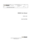
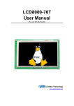
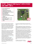
After the OTG bus has been switched, it is possible to connect UDOO to an external
computer plugged on CN3. The first time, Android will show an alert like that shown
in the following picture.
Android is asking to accept the fingerprint of the PC used. It is also possible to select
the option of remembering the choice; press OK button.
By launching a console on the host PC with the Android SDK installed, it is now
possible to access to UDOO using adb tool..
http://www.udoo.org/
20 UDOO Starting manual (beta)
Version 0.4
It is possible to download Android SDK and access the full documentation at:
http://developer.android.com/sdk/index.html
Full guide for ADB tool available at:
http://developer.android.com/tools/help/adb.html
3.2.6. Switching between modes
From Android options menu, it is possible to switch between Debug Mode and
Accessory Development Kit (ADK) Mode. For this, it is necessary to access the
android shell.
- Connect a microUSB cable to CN6 and plug J18 jumper. Now access to the shared
serial port using a terminal application (like Teraterm, Minicom, Serial Tools).
please check the paragraph related to the configuration of shared serial port
Accessing the Android console, it is possible to switch between the two modes.
From
INTERNAL ADK mode (i.Mx6 ←→ SAM3X)
to
Debug Mode (microUSB plugged in CN3)
From
Debug Mode (microUSB plugged in CN3)
to
INTERNAL ADK mode (i.Mx6 ←→ SAM3X)
sudo –s
echo 0 > /sys/class/gpio/gpio203/value
echo 0 > /sys/class/gpio/gpio128/value
sudo -s
echo 1 > /sys/class/gpio/gpio128/value
echo 1 > /sys/class/gpio/gpio203/value
When switching from Debug to ADK mode, after the two commands have been sent,
it is possible that it is necessary to reset the SAM3X8E. Simply plug and unplug the
jumper J16.
If it has been loaded a sketch implementing AOA protocol, an alert will appear. It
notifies that Android Accessory is now connected. In case of presence of an app
matching the id on the Arduino sketch, it will ask for a confirmation for opening such
an app..
On the top-left menu, a message will constantly remind about the presence of the
Accessory Connection.
3.3. Communication example over shared Serial Port
The two processors can communicate using the shared serial port, as deescribed in
paragraph 3.2.2
On i.MX6 processor, such a serial port can be managed using the device file
/dev/ttymxc3.
For example, on a UDOO Linux terminal, it is possible to initialize the serial port baud
rate by using the stty command:
http://www.udoo.org/
21 UDOO Starting manual (beta)
Version 0.4
e.g. stty -F /dev/ttymxc3 cs8 115200 (baud rate set to 115200)
(note: the baud rate have to be the same declared in SAM3x8E firmware)
(note: default baud rate is 9600)
to write a message on the serial port, use the echo command:
e.g. echo message > /dev/ttymxc3
to read messages from the serial port, use the cat command:
e.g. cat /dev/ttymxc3
This serial interface is directly connected to the serial programming port of
SAM3X8E, therefore in Arduino sketches it is possible to communicate with i.Mx6
using the Serial object.
To initialize the serial baud rate to the desired value, it is possible to use the method
begin(speed):
e.g. Serial.begin(115200);
(note: the baud rate have to be the same declared for i.MX6 processor)
to write a message on the serial port, use the methods print(val), println(val),
write(val):
e.g. Serial.print(45);
e.g. Serial.println(“Hello World”);
e.g. Serial.write(“udooooo”);
to read messages from the serial port, use the methods read(), readBytes():
e.g. Serial.read();
e.g. Serial.readBytes(buffer, length);
For a complete example on communication between the two processors, follow this
link www.udoo.org/features/processors-communication/ file containing an arduino
sketch (UDOO_test_communication_sketch.ino) and a linux bash script
(UDOO_test_communication_script.sh).
http://www.udoo.org/
22 UDOO Starting manual (beta)
Version 0.4
SAM3X8E microcontroller programmin
To program the Atmel SAM3x8E from an external Host PC, it is possible to use the
standard Arduino IDE.
4.1. Download Arduino IDE
Download the Arduino IDE for free at the official website:
http://arduino.cc/en/Main/Software
Download the version for the O.S. used (must be 1.5.2 or newer release).
4.2. Install Arduino IDE
Once downloaded the appropriate IDE, the next step is installing the Arduino IDE.
Keep in mind the path (from now on referenced as <ARDUINO_IDE_PATH>) for
extraction of the archive previously downloaded.
It is necessary to update the IDE by inserting a patch inside the
<ARDUINO_IDE_PATH> to make it fully compatible with UDOO board.
4.2.1. Windows
Download the installer or the zip package.
If it has been downloaded the zip file, then it is necessary to remember the path
where the file has been unzipped. Instead, if it has been donwloaded the installer, it
will copy all files needed in the following default path:
http://www.udoo.org/
23 UDOO Starting manual (beta)
Version 0.4
C:\Program Files (x86)\Arduino
4.2.2. Linux 32 / 64
Download the tar.gz files, choosing from 32 and 64 bit OS version.
Navigate in the download folder via terminal and write the command:
tar -zvf arduino-1.5.4-linux32.tgz
or
tar -zvf arduino-1.5.4-linux64.tgz
then move the folder in the preferred path
mv arduino-1.5.4 < PREFERRED_PATH>
4.2.3. OSX
Download and unzip the file, then move the App in Application folder.
4.3. Apply UDOO patch to Arduino IDE
To allow the Arduino IDE to work on UDOO, it is necessary to update a file in the
Arduino IDE folder.
Download the patch
Download the patch for the appropriate OS at following link:
www.udoo.org/downloads/#tab4
Extract the file called bossac from the archive and move it in the Arduino IDE path
overriding the old file (Answer “ yes” to any alert that will appear).
<ARDUINO_IDE_PATH>/hardware/tools/
On OS X, right click on the Arduino IDE Application and select “Show package
contents”, then copy the bossac file into:
<ARDUINO_IDE_PACKAGE>/Contents/Resources/Java/hardware/tools/
4.3.1. Why this patch is necessary
The Atmel SAM3x8E microcontroller needs to receive ERASE and RESET signals
before programming it with a new sketch.
On Arduino board this operation is performed by the microcontroller ATmega16U2,
which is not present on UDOO board. This patch solves this issue. The bossac file
sends a command to an i.MX6 embedded driver which acknowledges the command
and drive opportunely the SAM3x8E ERASE and RESET signals. Afterwards, the
http://www.udoo.org/
24 UDOO Starting manual (beta)
Version 0.4
SAM3x8E can be programmed with the new sketch.
UDOO also needs the driver to disable the internal shared serial port, used to upload
the sketch.
When the serial port is enabled on i.MX6then there will be three devices (i.MX6,
SAM3x8E, external PC) on the same line.
To avoid this conflict, the driver needs to set the i.MX6 serial port in INPUT MODE
before the bossac uploader sends the command to the SAM3x8E.
4.4. Alternative procedure
A different way for programming the Arduino side without applying patches
consists in stopping the board at U-boot stage before the Kernel is loaded
To do so you’ ll have to:
1.Download and install a serial monitor program (Teraterm for Windows, Minicom for
Linux, serial tools for OS X). Please check the appendix for the configuration and the
parameters of these software tools.
2. Connect the external Host PC through the microUSB port CN6, taking care that
jumper J18 is plugged. Then insert the power plug and start the system.
On the serial monitor it will appear something similar:
U-Boot 2009.08 (Sep 27 2013 - 12:30:44)
CPU: Freescale i.MX6 family TO1.2 at 792 MHz
Thermal sensor with ratio = 181
Temperature: 50 C, calibration data 0x5774fa69
mx6q pll1: 792MHz
mx6q pll2: 528MHz
mx6q pll3: 480MHz
mx6q pll8: 50MHz
ipg clock
: 66000000Hz
ipg per clock : 66000000Hz
uart clock : 80000000Hz
cspi clock : 60000000Hz
ahb clock
: 132000000Hz
axi clock
: 264000000Hz
emi_slow clock: 132000000Hz
ddr clock
: 528000000Hz
usdhc1 clock : 198000000Hz
usdhc2 clock : 198000000Hz
usdhc3 clock : 198000000Hz
usdhc4 clock : 198000000Hz
nfc clock
: 24000000Hz
Board: i.MX6Q-UDOO: unknown-board Board: 0x63012 [WDOG]
Boot Device: NOR
I2C: ready
DRAM: 1 GB
MMC: FSL_USDHC: 0,FSL_USDHC: 1,FSL_USDHC: 2,FSL_USDHC: 3
In: serial
Out: serial
Err: serial
Net: got MAC address from IIM: 00:00:00:00:00:00
FEC0 [PRIME]
Hit any key to stop autoboot: 3
Hit any key to stop autoboot: 2
http://www.udoo.org/
25 UDOO Starting manual (beta)
Version 0.4
Hit any key to stop autoboot: 1
3. Before the counter reaches 0, press any key on the external PC’ s serial console.
i.Mx6Q_UDOO_BOOT> _
4. Close the serial monitor and unplug J18 jumper. This will allow the communication
with the programming port of SAM3X8E;
5. Plug the jumper J22 for 1 second, then remove it (to erase the old sketch
programmed in SAM3X8E);
6. Plug the jumper J16 for 1 second, thend remove it (to reset the SAM3X8E);
7. Select from the IDE: Tools –> Board –> Arduino DUE programming port and select
the correct serial COM from the IDE;
8. Send the sketch using the IDE upload button.
9. Press the reset button to restart i.MX6 and use Ubuntu or Android again.
http://www.udoo.org/
26 UDOO Starting manual (beta)
Version 0.4
5. Shared GPIOs Management
5.1. Introduction
In this chapter it will be described how UDOO manages the signals available on
external pin header, and the way to control all the GPIOs. On UDOO, Freescale i.MX
and Atmel SAM3X8E share most of the GPIOs available on external pin headers.
Each pin of both processors can be set in INPUT or OUTPUT mode.
In INPUT mode, each processor read the electrical level of the signal.
In OUTPUT mode they can drive low or high the voltage level on each pin.
So both processors can control all digital external pins.
Usually, with Arduino Due, applications that manage external pins are developed to
run on the SAM3x8E microcontroller. On UDOO it is possible to control external pins
also using i.MX6 processor.
5.2. SAM3x8E GPI/Os management
SAM3x8E microcontroller can manage GPIOs using classic Arduino programming
language. More information on this topic can be found at
http://arduino.cc/en/Reference/HomePageTo manage a GPIO it is necessary to set
its direction (input or output) by calling the pinMode(pin, mode) function.
e.g. pinMode(2, INPUT );
pinMode(2, OUTPUT );
If pin is set in input mode, its value can be read by using the function
digitalRead(pin) providing pin number as parameter:
e.g. int val = digitalRead(2);
If pin is set in output mode, its value can be written by using the function
digitalWrite(pin, value)providing the pin number and the value that must be written
as parameters:
e.g. digitalWrite (2, HIGH) ; digitalWrite (2, LOW);
http://www.udoo.org/
27 UDOO Starting manual (beta)
Version 0.4
5.3. i.MX6 GPI/O Management
i.MX6 can handle external pins in many different ways. In default configuration, they
can be accessed from user level through the standard Kernel Linux interface.
Some of them can be configured for specific functionalities provided by i.MX6
architecture, like
spi, i2c, i2s, audiomux, pwms output, UARTs and so on.
In next sections it will be described the way to use such functionalities.
When a pin is set as a GPIO, it is possible to read its value, change its direction or
change output value directly from console.
All available GPIOs are managed by the kernel, and it is possible to access them
simply by reading or writing value in specific files placed in a specific folder.
In the /sys/class/gpio/ folder there are other sub-folders, one for each manageable
GPIO. Each sub-folder contains files that indicate:
● direction (in / out)
● value (0 / 1)
To read a GPIO direction:
cat /sys/class/gpio/gpioXX/direction
In or Out output is now expected
To change the pin direction:
echo out > /sys/class/gpio/gpioXX/direction
or
echo in > /sys/class/gpio/gpioXX/direction
It is possible to do the same for values read or written on the pin.
To read a pin (the value read will be correct only if pin’ s direction is set as input): :
cat /sys/class/gpio/gpioXX/value
0 or 1 output is expected
To write a value on a pin:
echo 0 > /sys/class/gpio/gpioXX/value
or
echo 1 > /sys/class/gpio/gpioXX/value
http://www.udoo.org/
28 UDOO Starting manual (beta)
Version 0.4
5.4. GPIOs Warnings
When changing i.MX6 GPIOs directions, it is necessary to pay special attention. New
direction must be compatible with SAM3x8E pinout configuration and/or with the
load of the physical pin.
http://www.udoo.org/
29 UDOO Starting manual (beta)
Version 0.4
A. GPIOs can be used to build a communication channel between the two
processors. By setting one processor in INPUT mode, and the other in OUTPUT
mode, a one-way channel will be created. Via software, it is possible to switch
the direction on both processors, in order to create a half-duplex
communication channel.
B. Two processors simultaneously can read data from external devices. They can
also write data to external devices or the other processor, but only one at a
time can be set in output mode.
C. The situations here illustrated must be avoided. In the first case, both
processors set the shared pin in output mode. If they try to drive the shared
line with different signal values, the resulting signal level will be unpredictable
and it could result in damaging the processor driving the signal LOW. The
same situation occurs when one external device tries to drive the shared line.
WARNING!
There isn’ t any automatic tool that can avoid dangerous situations. The programmer
must develop Hardware and Software able to avoid the occurrence of dangerous
situation.
http://www.udoo.org/
30 UDOO Starting manual (beta)
Version 0.4
6. i.MX6 Pinmuxing
6.1. Introduction
i.MX6 processor provides a dedicated controller for pin-muxing options, named
IOMUX Controller(IOMUXC). The IOMUX Controller allows to the IC to share one pad
between several functional blocks. The sharing is done by multiplexing the pad
input/output signals.
Every module requires a specific pad setting (such as pull up, keeper, and so on),
and for each signal, there are up to 8 muxing options (called ALT modes). The pad
settings parameters are controlled by the IOMUXC.
In the Linux kernel, it is necessary to define a specific file for each platform. For
UDOO, it can be found in:
<KERNEL_ROOT>/arch/arm/mach_mx6/board_mx6_seco_UDOO.c
This file contains specific drivers initializations, like ethernet, hdmi, sd, and so on..
At the beginningof the function __init mx6_seco_UDOO_board_init(void), there is
the following code:
if (cpu_is_mx6q () ) {
mxc_iomux_v3_setup_multiple_pads (mx6qd_seco_UDOO_pads,
ARRAY_SIZE (mx6qd_seco_UDOO_pads) );
printk ( "\n>UDOO quad" ) ;
}
else if ( cpu_is_mx6dl () ) {
mxc_iomux_v3_setup_multiple_pads (mx6sdl_seco_UDOO_pads,
ARRAY_SIZE (mx6sdl_seco_UDOO_pads) );
printk ( "\n>UDOO dual " ) ;
}
It recognizes the UDOO version used, and load the necessary macros needed for it.
mx6qd_seco_UDOO_pads and mx6sdl_seco_UDOO_pads are two array of macros
defined in two header files, one for each processor type. Both .h files are included in
the .c file.
<KERNEL_ROOT>/arch/arm/mach_mx6/board_mx6qd_seco_UDOO.h (QUAD)
<KERNEL_ROOT>/arch/arm/mach_mx6/board_mx6sdl_seco_UDOO.h (DUAL)
mxc_iomux_v3_setup_multiple_pads reads the macros and set the correct bits
values in registers.
Each header file defines:
● custom macros for some pins
● GPIOs id number (i.MX6 pins are divided in banks and identified by id. To
make them visible by the OS it is necessary to give them a single id number.
IMX_GIPO_NR provide this function).
● macro’ s array used for pinmuxing
● an array containing the pins set as GPIOs that must be configured in output
mode with high value
http://www.udoo.org/
31 UDOO Starting manual (beta)
●
●
Version 0.4
an array containing the pins set as GPIOs that must be configured in output
mode with low value
an array containing the pins set as GPIOs that must be configured as inputs
It is also possible to divide the pins in two sets:
● internal pins, used for communications between processors, to enable or
disable external peripherals (ethernet, usb hub, audio... )
● external pins, accessible from external through the Arduino Due compatible
pin headers
External pins are set in input mode, in order to prevent problems with SAM3x8E
signals.
To set directions and output value for the pins defined previously as GPIOs, it is
necessary to place the GPIOs macors defined in header file’ s beginning (eg.
MX6DL_PAD_SD2_DAT0__GPIO_MODE) into the arrays named:
●
●
●
mx6dl_set_in_outputmode_low[]
mx6dl_set_in_outputmode_high[]
mx6dl_set_in_inputmode[]
respectively.
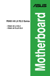
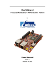
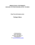
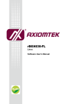
6.2. Extra functions available on UDOO pin headers
UDOO can provide for extra features on external pin headers. To enable them it is
necessary to declare the correct alternative pin function in the platform file.
These
●
●
●
●
●
●
●
●
●
●
●
functions are:
UARTs: uart1, uart3, uart4, uart5
sd1
SPIs: spi1, spi2, spi5
i2c1
spdif
timer capture
timer compare
WATCHDOG FUNCTIONALITIES: watchdog reset, watchdog out
clock out
PWMs: pwm1, pwm2, pwm3, pwm4
digital audio
http://www.udoo.org/
32 UDOO Starting manual (beta)
Version 0.4
Looking at the previous diagram, on the vertical axis there is the functionality
provided by iMx6. On the horizontal axis are shown the pins used to implements
each functionality. Be careful that some pins are used for different functionalities
and only one at a time can be active for each of them.
6.3. Example
As an example, consider the possibility of enabling another serial port (UART3)
connected to imx6 through external Pins.
For this, it is necessary to edit the file board-mx6qd_seco_UDOO.h.
Looking at the previous graph, it is possible to see that needed pins areEIM_D24 and
EIM_D25.
Now it is possible to select the correct macros to enable this functionality. It is also
necessary to remove the related GPIOs macro from the mx6q_set_in_inputmode[]
array, which contains the list of the pins configured as input GPIOs.
static iomux_v3_cfg_t mx6qd_seco_UDOO_pads[] = {
...
static iomux_v3_cfg_t mx6qd_seco_UDOO_pads[] = {
...
MX6Q_PAD_EIM_CS1__GPIO_2_24,
//
MX6Q_PAD_EIM_CS1__ECSPI2_MOSI,
MX6Q_PAD_EIM_CS0__GPIO_2_23,
//
MX6Q_PAD_EIM_CS1__GPIO_2_24,
//
MX6Q_PAD_EIM_CS1__ECSPI2_MOSI,
MX6Q_PAD_EIM_CS0__GPIO_2_23,
//
http://www.udoo.org/
33 UDOO Starting manual (beta)
Version 0.4
MX6Q_PAD_EIM_CS0__ECSPI2_SCLK,
MX6Q_PAD_EIM_CS0__ECSPI2_SCLK,
MX6Q_PAD_EIM_D24__GPIO_3_24,
//
MX6Q_PAD_EIM_D24__ECSPI2_SS2,
//
MX6Q_PAD_EIM_D24__UART3_TXD,
// MX6Q_PAD_EIM_D24__ECSPI1_SS2,
MX6Q_PAD_EIM_D25__GPIO_3_25,
//
MX6Q_PAD_EIM_D25__UART3_RXD,
// MX6Q_PAD_EIM_D24__GPIO_3_24,
//
MX6Q_PAD_EIM_D24__ECSPI2_SS2,
MX6Q_PAD_EIM_D24__UART3_TXD,
// MX6Q_PAD_EIM_D24__ECSPI1_SS2,
// MX6Q_PAD_EIM_D25__GPIO_3_25,
MX6Q_PAD_EIM_D25__UART3_RXD,
MX6Q_PAD_GPIO_7__GPIO_1_7,
//
MX6Q_PAD_GPIO_7__CAN1_TXCAN,
MX6Q_PAD_GPIO_8__GPIO_1_8,
//
MX6Q_PAD_GPIO_8__CAN1_RXCAN,
MX6Q_PAD_GPIO_7__GPIO_1_7,
//
MX6Q_PAD_GPIO_7__CAN1_TXCAN,
MX6Q_PAD_GPIO_8__GPIO_1_8,
//
MX6Q_PAD_GPIO_8__CAN1_RXCAN,
MX6Q_PAD_EIM_WAIT__GPIO_5_0_CORRECT,
};
MX6Q_PAD_EIM_WAIT__GPIO_5_0_CORRECT,
};
static unsigned int mx6q_set_in_inputmode[] = {
static unsigned int mx6q_set_in_inputmode[] = {
...
...
MX6Q_PAD_EIM_CS1__GPIO_MODE,
MX6Q_PAD_EIM_CS0__GPIO_MODE,
MX6Q_PAD_EIM_CS1__GPIO_MODE,
MX6Q_PAD_EIM_CS0__GPIO_MODE,
// MX6Q_PAD_EIM_D24__GPIO_MODE,
// MX6Q_PAD_EIM_D25__GPIO_MODE,
MX6Q_PAD_EIM_D24__GPIO_MODE,
MX6Q_PAD_EIM_D25__GPIO_MODE,
MX6Q_PAD_GPIO_8__GPIO_MODE,
MX6Q_PAD_GPIO_7__GPIO_MODE,
MX6Q_PAD_GPIO_8__GPIO_MODE,
MX6Q_PAD_GPIO_7__GPIO_MODE,
};
};
Once all needed changes to configuration files have been made, it is necessary to
compile again the kernel source.
WARNING: the pins EIM_D24 and EIM_D25 are shared with SAM3x8E .
EIM_D24 -> digital pin 53
EIM_D25 -> digital pn 47
void setup ( ) {
Serial.begin(115200) ;
pinMode(47 , INPUT ) ;
pinMode(53 , INPUT ) ;
}
void loop ( ) {
// ... some stuff ...
}
7. Appendix
7.1. How to create a Virtual Machine Environment
7.1.1. Introduction
http://www.udoo.org/
34 UDOO Starting manual (beta)
Version 0.4
The use of a virtual machine running a specific Linux Ubuntu distribution is highly
recommended. .
A virtual machine will create a dedicated, close environment that will ensure that a
step-by-step procedure will guide the user until the end without problems. It also prevent risks ofsystem corruption or that compiling environment is not clean
It also allows to be sure that used libraries are always the same, and updated.
System Requirements
To run the procedure described in the following sections, it is necessary to have:
PC with virtual machine running Linux Ubuntu 10.04 with at least 40 GB of free disk
space.
● UDOO Board
● micro-SD at least 4GB
● An SD card reader
● A micro-USB to USB cable
To try immediately UDOO Board, it is also necessary:
● HDMI monitor
● HDMI cable
● Mouse
● Keyboard
● UDOO compatible power supply
This procedure can be performed also on native Linux OS. The use of a VM only
reduces system differences and can follow a standardised procedure to compile
Android.
7.1.3. Setting up work environment
Install the Virtual Machine
VMware PlayerTM is recommended for this operation. A step-by-step
installationProcedure is provided.
Mac users
Virtual Box player can be used; however the procedure has not been tested on this
system.
Download the VM player
Download the player from VMware Player website:
You can find the latest st version at http://www.vmware.com/products/player/ .
Choose the version dedicated to the OS used.
Install the VM on your system
Open the installer and follow the instructions.
For more information, check the VMware documentation:
http://www.vmware.com/pdf/VMwarePlayerManual10.pdf
http://www.udoo.org/
35 UDOO Starting manual (beta)
Version 0.4
Download Ubuntu disk image
A 64 bit 10.04 Ubuntu distro to run this procedure is recommended. It can be
downloaded from http://old-releases.ubuntu.com/releases/lucid/
Create a new VM running Ubuntu 10.04
Click on VMware Player icon.
Choose “Create a New Virtual Machine” from menu on the right
Choose “Installer disk image file (iso)” and select the downloaded ubuntu iso image..
Press Next button.
Then choose your name, the username and the password. Fill these fields and click
on next button.
Choose the VM name: UDOO-dev-10.04 and click next.
Set harddisk size at least 40 GB. Unfortunately, compiling Android OS requires a big
amount of disk space.
Select “split virtual disk into multiple files” option.
Now it is necessary to set VM performances by clicking on “customize hardware”
button.
Memory Options:
● 1 GB minimum (low performance, lot of swapping during the compiling)
● 2 GB recomended (memory swapping especially during java compiling)
● 3 GB+ perfect (no memory swapping during build operations)
Attention
The memory size must be chosen according to the amount of free memory on the
host computer. When large amount of memory are assigned to VM, then the host OS
could repeatedly swap or page, leading to a drastic decrease of computer’ s
performances.
CPUs:
All the available CPU cores of the host PC should be assigned to VM execution,
especially for the first compiling which requires a lot of time. After the first phase, it
is possible to reduce the number of CPU cores, if desired.
Then click on “Finish” button and Ubuntu installation will start.
When the installation has ended, it is possible that it is necessary to login from
console and launch the GUI by running the command:
startx
Setting up VM environment
Update the system
sudo apt-get update
Install required libraries for Android compiling process:
sudo apt-get install git-core gnupg flex bison gperf build-essential \
zip curl zlib1g-dev libc6-dev lib32ncurses5-dev ia32-libs \
x11proto-core-dev libx11-dev lib32readline5-dev lib32z-dev \
http://www.udoo.org/
36 UDOO Starting manual (beta)
Version 0.4
libgl1-mesa-dev g++-multilib mingw32 tofrodos python-markdown \
libxml2-utils xsltproc uuid-dev liblzo2-dev
http://www.udoo.org/
37 UDOO Starting manual (beta)
Version 0.4
7.2. Establish serial debug connection with UDOO
7.2.1. Introduction
This chapter will describe the way to install, configure and access he i.Mx6 Serial
Debug Port.
Obviously, it is possible to use all kind of tool to to access serial. This is just a basic
guide for beginners.
The access to debug serial port is very important on UDOO, since it is a very
compact board but with a very high level of complexity inside. It can be useful for
many operations during setup, control, configuration, debug, troubleshooting…
The serial debug port is used for two different reasons:
● The bootloader and kernel send debug messages via serial port, so that the
user can monitor the low level system states;
● A root console is automatically opened on the serial port, allowing bootloader
configuration and system control.
The number of messages sent via serial port can be very high. For this reason, it is
quite useful to increase scrolling capabilities of the terminal, possibly setting them to
a very high or even unlimited number of lines.
Three programs to access serial ports are suggested, depending on the OS used on
th e host PC.
● Teraterm (Windows)
● Minicom (Linux)
● Serial Tools (Mac)
7.2.2. Drivers
Windows and Mac users may need to install drivers to access UDOO usb serial.
They can be found at
http://www.silabs.com/products/mcu/pages/usbtouartbridgevcpdrivers.aspx
7.2.3. Windows
Download
Download the installer from:
http://logmett.com/freeware/TeraTerm.php
http://www.udoo.org/
38 UDOO Starting manual (beta)
Version 0.4
Accept the license term and press the download button.
Installation
Follow the instructions of the installer.
http://www.udoo.org/
39 UDOO Starting manual (beta)
Version 0.4
Select the “Standard installation”, and press next.
http://www.udoo.org/
40 UDOO Starting manual (beta)
Version 0.4
http://www.udoo.org/
41 UDOO Starting manual (beta)
Version 0.4
Press next until appears “Install” button, and press it.
When installation has ended, open Tera Term.
http://www.udoo.org/
42 UDOO Starting manual (beta)
Version 0.4
Configuration
Now it is necessary to configure properly the serial port in order to match i.Mx6
debug serial port.
Open “Setup” menu and select “Setup port…”
In the following picture are shown the correct parameters needed to talk with i.MX6
Debug Serial Port.
Press “OK”.
Usage
Plug the USB cable to CN6 on UDOO and to an USB port of the host PC. The chip is
powered by the USB cable, so it will be shown a serial port connected to the PC
Please be aware that if UDOO main power plug is not connected, then USB power
supply is insufficient to let UDOO run.
Open File menu, select “New connection…” (Alt+N) and choose the correct serial port.
http://www.udoo.org/
43 UDOO Starting manual (beta)
Version 0.4
Press OK, then turn on UDOO board.
7.2.4. Linux
First of all it is necessary to install minicom
HOST$ sudo apt-get install minicom
Launch minicom in setup mode (and with Linewrap ON; this is not necessary, but it is
useful)
HOST$ sudo minicom -sw
Select “Serial port setup” and check the following parameters:
- Serial Device, option A (usually, /dev/ttyS0 or /dev/ttyUSB0 in case an USB
adapter is used)
- Communications parameters, option E (must be 115200 8N1)
- No flow control, neither hardware nor software, options F and G
Save the settings as default
“Exit” will close setup and open minicom. Instead, select “Exit from minicom” to close
it completely. Launch minicom again without setup options
HOST$ sudo minicom -w
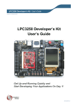
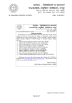
7.2.5. Mac OSX
Download Serial Tools from:
https://itunes.apple.com/it/app/serialtools/id611021963
or directly from Apple Store.
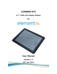
Open Serial Tools, then change the following two parameters:
- the “Serial Port” name to “SLAB_USBtoUART” (or similar)
- the baudrate to 115200
http://www.udoo.org/
44 UDOO Starting manual (beta)
Version 0.4
Click on “Connect”.
The picture above shows an example of output.
http://www.udoo.org/
45 UDOO Starting manual (beta)
Version 0.4
7.2.6. Final steps
By turning on UDOO, a lot of output lines coming out from UDOOs Serial Debug port
will be shown on the serial port terminal. About 30 seconds after, it should be
possible to access Linux or Android shell.
Android:
root@android:/ #
Linux Ubuntu:
Ubuntu 11.10 imx6-qsdl ttymxc1
imx6-qsdl login:
http://www.udoo.org/
46