1
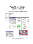
Visual MODFLOW 3D-Builder Quick Reference Guide Visual MODFLOW 3D-Builder Quick Reference Guide Visual MODFLOW 3D-Builder Quick Reference Guide Introduction This document describes the basic use of Visual MODFLOW 3D-Builder and guides you through the general workflow for creating your first conceptual model. It provides “step-wise” instructions on how to create a new project, import data, create structural zones and horizons, define property zones, create boundary conditions, and finally, import your model into Visual MODFLOW. For more detailed information on all features available in 3D-Builder, please refer to the online help or your User’s Manual. This can be accessed by selecting Help and then Help Topics from the 3D-Builder main menu. When following this guide, you may use your own data, or you may use the provided sample files located in your Documents \ 3D-Builder Projects \ Quick Reference Guide Files folder. This sample data appears in the screen captures of this guide. Topics Creating a New Project .......................................................................................................................................2 Defining Project Settings.....................................................................................................................................2 Importing Data.....................................................................................................................................................3 Viewing Imported Data in 3D and 2D..................................................................................................................5 Creating Surfaces from Points.............................................................................................................................7 Creating and Drawing a New Data Object..........................................................................................................8 Creating a New Conceptual Model .....................................................................................................................9 Creating Horizons .......................................................................................................................................10 Viewing Horizons........................................................................................................................................11 Viewing Structural Zones...........................................................................................................................11 Creating Property Zones.............................................................................................................................12 Defining the Simulation Domain .......................................................................................................................14 Defining Pumping Wells....................................................................................................................................15 Defining a Recharge Boundary Condition..........................................................................................................17 Defining a General Head Boundary Condition...................................................................................................19 Defining a Numerical Model Grid......................................................................................................................21 Translate to a Numerical Model........................................................................................................................23 Importing Into Visual MODFLOW ......................................................................................................................25 Table of Supported Data Types....................................................................................................................26 1 Schlumberger Water Services | 460 Phillip St., Ste. 101, Waterloo, On N2L 5J2 | Phone: +1 (519) 746-1798 | Fax: + 1 (519) 885-5262 www.swstechnology.com | [email protected] VMOD 3D Builder | Quick-Reference Guide, Page 1, Rev. 9/30/2008 Visual MODFLOW 3D-Builder Quick Reference Guide Creating a New Project 1. Start 3D-Builder by double-clicking on the desktop icon or by selecting Start / Programs / SWS Software / Visual MODFLOW / Visual MODFLOW 3D-Builder. 2. From the main-menu, select File / New / Project… Defining Project Settings 1. Enter a unique project name in the Name field. 2. Click the Open button and select a location on your computer where all project data will be saved. 3. Select the appropriate coordinate system from the Coordinate Systems combo box. The project name cannot contain special characters such as \ / :* ?”< > | . 4. Define the unit system for your project by selecting the appropriate units for each parameter listed in the Unit Settings grid. If you do not know this information, you can leave the default settings and modify the units at a later time. 5. Click the [Ok] button to save the Project Settings, and complete the projection creation. You can edit the project settings at any time by clicking Project / Settings from the main menu. 2 Schlumberger Water Services | 460 Phillip St., Ste. 101, Waterloo, On N2L 5J2 | Phone: +1 (519) 746-1798 | Fax: + 1 (519) 885-5262 www.swstechnology.com | [email protected] VMOD 3D Builder | Quick-Reference Guide, Page 2, Rev. 9/30/2008 Visual MODFLOW 3D-Builder Quick Reference Guide Importing Data 1. Right-click anywhere in the Input tab and select Import Data… from the pop-up menu, or click File / Import from the main menu. Input tab 2. The Data Import dialog will appear where you can specify the Data Type, Source File, Data Object Name and Description (optional). The supported file formats depend on the selected data type. To see a list of supported file types please see Supported File Types on page 26. Supported data types in 3D-Builder 1 Data Type Click the Source File Name button and select the source file from a location on your computer Click the Type a unique name for the data type button and select the desired data type from the combo box 3. Click the [Next] button to continue. 3 Schlumberger Water Services | 460 Phillip St., Ste. 101, Waterloo, On N2L 5J2 | Phone: +1 (519) 746-1798 | Fax: + 1 (519) 885-5262 www.swstechnology.com | [email protected] VMOD 3D Builder | Quick-Reference Guide, Page 3, Rev. 9/30/2008 Visual MODFLOW 3D-Builder Quick Reference Guide 4. The remaining steps may vary slightly depending on which data type is selected. The general workflow is shown below: The source file for data shown in the import screen captures is Points.xls, located in your Documents \ 3D- Builder Projects folder 3 2 Prepare and preview the source data. This step is only required when importing Points, Time Schedule and Well data. 4 Select the coordinate system of the source data. If the coordinate system of the source data is different than the project’s coordinate system, a geotransformation will be performed. 5 Map the source data fields to the target fields and create attributes. In the Map_to column, click in each field, and then select the corresponding target field from the combo box. For each mapped field, specify the Unit Category, Unit, Multiplier and Data Type. Click the green [+] button to create a new attribute. Attributes can be created for Wells, Polylines, Polygons, Points and Time Schedules. In the final step the mapped data is validated. All rows that contain invalid data will be highlighted yellow or red in the Mapped Data Preview frame. Select the Do not import rows with warning checkbox to exclude this data from the data import. 5. Once imported, the data object will appear in the Input tab. For more information on importing data into 3D-Builder, please refer to Chapter 3 of your User’s Manual. Imported Data 4 Schlumberger Water Services | 460 Phillip St., Ste. 101, Waterloo, On N2L 5J2 | Phone: +1 (519) 746-1798 | Fax: + 1 (519) 885-5262 www.swstechnology.com | [email protected] VMOD 3D Builder | Quick-Reference Guide, Page 4, Rev. 9/30/2008 Visual MODFLOW 3D-Builder Quick Reference Guide Viewing Imported Data in 3D and 2D To view your data in a 3D Viewer Window, follow the steps below: 1. From the main menu, click Window \ New 3D Window Most data objects can also be viewed in a 2D planar view. To view your data in 2D, click Window \ New 2D Window from the main menu. Upon clicking, a new 3D Window will appear. You can resize the window by clicking and dragging the window corners, or simply click the button in the top-right corner to maximize the window. 2. To display imported data in the 3D Viewer, simply select the box the input tab so that it appears checked . beside the data object name in Surfaces shown in this screen capture were generated from Points.xls located in your Documents \ 3D Builder Projects folder 5 Schlumberger Water Services | 460 Phillip St., Ste. 101, Waterloo, On N2L 5J2 | Phone: +1 (519) 746-1798 | Fax: + 1 (519) 885-5262 www.swstechnology.com | [email protected] VMOD 3D Builder | Quick-Reference Guide, Page 5, Rev. 9/30/2008 Visual MODFLOW 3D-Builder Quick Reference Guide 3. Once the data is displayed in the 3D Window, you can zoom in and out, rotate and move the data within the window, using your mouse. Rotate Click and hold the left mouse button anywhere in the 3D Viewer Window and move the mouse to rotate the data. You can change the color of the 3D Viewer Window by selecting Background Color from the right-click pop-up menu. Move Right-click anywhere in the 3D Viewer Window and select Move from the pop-up menu. Then, click the hold the left mouse button and move the mouse to move the data left, right, up or down. Right-click pop-up menu Zoom Place your mouse anywhere in the 3D Viewer Window and move your scroll wheel on your mouse forward to zoom in and backwards to zoom out. 4. You can set the vertical exaggeration by entering a value in the Exaggeration text field located at the bottom of the 3D Viewer Window, and pressing [Enter] on your keyboard. You can also change Up and Down arrows. the vertical exaggeration using the 6 Schlumberger Water Services | 460 Phillip St., Ste. 101, Waterloo, On N2L 5J2 | Phone: +1 (519) 746-1798 | Fax: + 1 (519) 885-5262 www.swstechnology.com | [email protected] VMOD 3D Builder | Quick-Reference Guide, Page 6, Rev. 9/30/2008 Visual MODFLOW 3D-Builder Quick Reference Guide Creating Surfaces from Points Imported points data objects can be interpolated to create surfaces. These surfaces can then be used to generate horizons for your conceptual model. To create surfaces from a points data object, follow the steps below. 1. From the Input tab, right-click anywhere and select the Create Surfaces… from the pop-up menu. 2. The Create Surface dialog will appear on your screen. Specify the general settings described below. Surface Name: Type a unique name for the surface Description (Optional): Type a description for the surface. Data Source: Surfaces can be generated from one or more points data objects. To add a points data object, • • • • button to add a Click the Add new data source. Select the desired points data object from the Input tab, and then click the button. Blue Arrow Under the Z Value column, select the desired attribute from the combo box Repeat to add additional points data objects. 3. Click the Interpolation Settings tab, and specify the desired Interpolation method. For more information on the interpolation settings, please refer to your 3D-Builder User’s Manual. 4. Click the [Ok] button to generate the surface data object. Once generated, a new surface data object will be added to the Input tab. 7 Schlumberger Water Services | 460 Phillip St., Ste. 101, Waterloo, On N2L 5J2 | Phone: +1 (519) 746-1798 | Fax: + 1 (519) 885-5262 www.swstechnology.com | [email protected] VMOD 3D Builder | Quick-Reference Guide, Page 7, Rev. 9/30/2008 Visual MODFLOW 3D-Builder Quick Reference Guide Creating and Drawing a New Data Object To create a new Point, Polyline or Polygon data object, follow the steps below. 1. From the Input tab, right-click anywhere and select Create New Data Object… from the pop-up menu. 2. The Create New Layer dialog box will appear on your screen (shown below). Specify the following settings: Layer Type: Select which type of data object to create. Choose between Point, Polyline and Polygon. Layer Name: Type a unique name for the data object. 3. Click the [Ok] button to create the new data object. A new data object will be added to the Input tab. 4. Using the 2D Viewer drawing tools, you can draw the geometry of the new data object. Open a new 2D Viewer window by selecting Window \ New 2D Window from the main menu. 5. Make sure the new data object is “checked” in the Input tab. 6. You can display other data objects in the 2D Viewer while drawing the geometry of the new data object. However, make sure that the new data object is the “active” one by selecting it in the Layer combo box, located at the bottom of the 2D Viewer. 7. From the 2D Viewer sidebar, select the Pick Mode button. 8. From the 2D Viewer sidebar, select the Edit button. Various buttons will be added to the 2D Viewer side bar. These buttons allow you to draw points, polygons and polylines in the 2D Viewer. For a complete description of the editing buttons, please refer to the section “Digitizing & Editing Geometry in 2D Viewers” in Chapter 5 of your 3D-Builder User’s Manual. 9. Draw the geometry of the data object in the 2D Viewer using the drawing tools. 10. Once you have finished drawing your shape(s), click the 11. Finally, click the End Edit button from the sidebar. View Mode button to set the viewer back to normal viewing mode. 8 Schlumberger Water Services | 460 Phillip St., Ste. 101, Waterloo, On N2L 5J2 | Phone: +1 (519) 746-1798 | Fax: + 1 (519) 885-5262 www.swstechnology.com | [email protected] VMOD 3D Builder | Quick-Reference Guide, Page 8, Rev. 9/30/2008 Visual MODFLOW 3D-Builder Quick Reference Guide Creating a New Conceptual Model Once your raw data is imported into 3D Builder, you can create a conceptual model. The minimum data requirements for creating a conceptual model is two surfaces and one polygon that defines the model boundary. 1. From the main menu, select File \ New \ Conceptual Model… 2. A New Conceptual Model dialog will appear, where you can define the settings for the conceptual model. The General settings are described below. Name Type a unique name for the conceptual model Description (optional) Type a description for the conceptual model Start Date Select the start date of the conceptual model by clicking on the button and selecting a date from the pop-up calendar. Model Area Select a polygon data object from the Input tab that represents the boundary of the model area. Once selected, click the button. Projection Type By default, the projection type will be the same as the project’s projection type, defined in the project settings. This setting is for reference only, and cannot be changed. 3. Once the required data has been entered, click the [Ok] button, and a conceptual model tree will be added to the Conceptual Model tab. 9 Schlumberger Water Services | 460 Phillip St., Ste. 101, Waterloo, On N2L 5J2 | Phone: +1 (519) 746-1798 | Fax: + 1 (519) 885-5262 www.swstechnology.com | [email protected] VMOD 3D Builder | Quick-Reference Guide, Page 9, Rev. 9/30/2008 Visual MODFLOW 3D-Builder Quick Reference Guide Creating Horizons Horizons are stratigraphic layers that form the upper and lower boundaries for structural zones in the conceptual model. Horizons are generated using existing surface data objects in the Input tab. To create horizons, follow the step below: 1. From the Conceptual Model tree, right-click the Structure node and select Create Horizons… from the pop-up menu. 2. The Horizon Settings dialog will load. Click the Add button to add a horizon. 3. Select a surface data object from the Input tab and then click the button. Repeat step 2 and 3 for additional horizons. Note: Surfaces must be added according to elevation, starting with the top surface (ground surface) and ending with the bottom surface. A conceptual model requires at least two horizons. Horizon Types In the Name column, type a name for each horizon and select the horizon type from the Type column. For more information on the different types of horizons, please refer to the User’s Manual. 4. Click the [Apply] button to preview the horizons. 5. Click the [Ok] button to create the horizons. The created horizons will now appear under the Horizons node in the Conceptual Model tree. 10 Schlumberger Water Services | 460 Phillip St., Ste. 101, Waterloo, On N2L 5J2 | Phone: +1 (519) 746-1798 | Fax: + 1 (519) 885-5262 www.swstechnology.com | [email protected] VMOD 3D Builder | Quick-Reference Guide, Page 10, Rev. 9/30/2008 Visual MODFLOW 3D-Builder Quick Reference Guide Viewing Horizons 1. With a 3D Viewer Window opened, expand the Horizons node in the Conceptual Model tree and select the box beside each horizon name so that it appears checked Horizon 1 Horizon 2 Horizon 3 Viewing Structural Zones Structural Zones are generated automatically when horizons are created. To view structural zones in a 3D-Viewer, follow the steps below: 1. With a 3D Viewer Window opened, expand the Zones node in the Conceptual Model tree and select the box beside each zone name so that it appears checked 11 Schlumberger Water Services | 460 Phillip St., Ste. 101, Waterloo, On N2L 5J2 | Phone: +1 (519) 746-1798 | Fax: + 1 (519) 885-5262 www.swstechnology.com | [email protected] VMOD 3D Builder | Quick-Reference Guide, Page 11, Rev. 9/30/2008 Visual MODFLOW 3D-Builder Quick Reference Guide Creating Property Zones 1. From the Conceptual Model tree, right-click on the Properties node and select Define Property Zone 2. Upon clicking, the New Property Zone dialog will display: Name Type in a unique name for the property zone Description (Optional) Type in a description of the property zone Select method for creating property zone Select a method by clicking the desired radio button. This guide describes the steps for the Define property zone using structural zone method. For information on defining property zones using a polygon data object, please refer to the 3D Builder User’s Manual. Select one or more structural zones From the Conceptual Model Tree, select a structural zone, and then click the button. 12 Schlumberger Water Services | 460 Phillip St., Ste. 101, Waterloo, On N2L 5J2 | Phone: +1 (519) 746-1798 | Fax: + 1 (519) 885-5262 www.swstechnology.com | [email protected] VMOD 3D Builder | Quick-Reference Guide, Page 12, Rev. 9/30/2008 Visual MODFLOW 3D-Builder Quick Reference Guide 3. Click the [Next] button to continue. 4. Select the group of parameters for which attributes will be defined, e.g., conductivity, storage or initial heads. 5. In the data input grid, select the method for each parameter from the Method combo box, e.g., Constant Value, Use Surface, Use 3D-Gridded Data. For more information on the different methods for assigning attribute values, please refer to the User’s manual. 6. Assign values to each parameter according to the specified method. For example, if you selected constant value for an attribute, specify a constant value in the value field. If you selected use surface method for an attribute, click the Use Surface button, and specify a surface data object from the Input tab. 7. Once values have been assigned, click the [Finish] button to create the property zone. 8. Repeat the steps above to create additional property zones. The created property zone will now appear under Properties node in the Conceptual Model Tree. You can view the property zone in 3D Viewer Window by checking the white box beside the property. 13 Schlumberger Water Services | 460 Phillip St., Ste. 101, Waterloo, On N2L 5J2 | Phone: +1 (519) 746-1798 | Fax: + 1 (519) 885-5262 www.swstechnology.com | [email protected] VMOD 3D Builder | Quick-Reference Guide, Page 13, Rev. 9/30/2008 Visual MODFLOW 3D-Builder Quick Reference Guide Defining the Simulation Domain To define a simulation domain, follow the steps below: 1. From the Conceptual Model Tree, right-click on the Simulation Domain node, and select Generate Default Simulation Domain from the pop-up menu. 2. Expand the Simulation Domain node. You will see that it has created the “Model Domain”; this volume is defined by the conceptual model area and the upper-most and lower-most horizons. 3. If a 3D Viewer window is opened, you can view the geometry of the simulation domain by selecting the white box located beside the “Model Domain” node. 14 Schlumberger Water Services | 460 Phillip St., Ste. 101, Waterloo, On N2L 5J2 | Phone: +1 (519) 746-1798 | Fax: + 1 (519) 885-5262 www.swstechnology.com | [email protected] VMOD 3D Builder | Quick-Reference Guide, Page 14, Rev. 9/30/2008 Visual MODFLOW 3D-Builder Quick Reference Guide Defining Pumping Wells Before you can create pumping wells, you must import a wells data object into your 3D-Builder project. To define pumping wells, follow the steps below. 1. Right-click on the Boundary Conditions in the conceptual model tree, and select Define Pumping Well Boundary Condition from the pop-up menu. 2. Upon selecting, the following dialog will appear. Enter the following data: Name Type in a unique name for boundary condition. Description Optional Type in a description of the boundary condition. Select Wells Data Object Select a wells data object from the Input tab, and then click the button. 3. Click the [Next] button to proceed to the next step. The following dialog will display: This dialog displays all the pumping wells for the selected wells data object. Here you can select which pumping wells to include in the boundary condition. By default, all wells will be selected (highlighted blue), however, you can select the desired wells by holding the [CTRL] key and clicking each well. Click the [Show>>] button to view a preview of the wells in a 3D Viewer window. 15 Schlumberger Water Services | 460 Phillip St., Ste. 101, Waterloo, On N2L 5J2 | Phone: +1 (519) 746-1798 | Fax: + 1 (519) 885-5262 www.swstechnology.com | [email protected] VMOD 3D Builder | Quick-Reference Guide, Page 15, Rev. 9/30/2008 Visual MODFLOW 3D-Builder Quick Reference Guide 4. Click the [Next] button to proceed to the next step. The following dialog will display: At this step, each pumping wells is validated to ensure that the following requirements are met: Check this box to ignore all invalid pumping wells. The pumping well coordinates must fall within the conceptual model boundary domain The pumping well must have a defined pumping schedule The pumping well must have a defined screen. If a well does not meet all of the above requirements, it is colored red in the Mapped Data Preview table. 5. Click the [Next] button to proceed to the next step. The following dialog will display: Here you can preview the pumping schedule and screen details for each pumping well. Simply select a pumping well from the Well Details table, and the corresponding pumping schedule and screen details will be shown in the adjacent Pumping Schedules and Screen Details table. Note: The data shown in this dialog is read-only. If you want to make changes to the pumping schedule or screen information, you can do so using the pumping well data table. For more information on modifying well data, please refer to the User’s Manual. 6. Click the [Finish] button to generate the boundary condition. The boundary condition will now appear under the Boundary Conditions node in the conceptual model tree, and can be viewed in a 3D-Viewer or 2D-Viewer window. 16 Schlumberger Water Services | 460 Phillip St., Ste. 101, Waterloo, On N2L 5J2 | Phone: +1 (519) 746-1798 | Fax: + 1 (519) 885-5262 www.swstechnology.com | [email protected] VMOD 3D Builder | Quick-Reference Guide, Page 16, Rev. 9/30/2008 Visual MODFLOW 3D-Builder Quick Reference Guide Defining a Recharge Boundary Condition To create a recharge boundary condition, follow the steps below: 1. Right-click on the Boundary Conditions in the conceptual model tree, and select Add Boundary Condition… from the pop-up menu. 2. The Define Boundary Condition dialog box will appear on your screen (shown below). • Select Recharge from the Select Boundary Condition Type combo box • Specify a Name and optionally a Description • Select the location of the boundary condition from the Where to connect on the Simulation Model Domain combo box. For Recharge boundary conditions, the available options are Top and Intermediate. • From the Input tab, select a polygon data object that represents the recharge area and click the Blue Arrow button. 17 Schlumberger Water Services | 460 Phillip St., Ste. 101, Waterloo, On N2L 5J2 | Phone: +1 (519) 746-1798 | Fax: + 1 (519) 885-5262 www.swstechnology.com | [email protected] VMOD 3D Builder | Quick-Reference Guide, Page 17, Rev. 9/30/2008 Visual MODFLOW 3D-Builder Quick Reference Guide 3. The next step involves assigning boundary condition parameters. • For the Recharge parameter, select either Static or Transient from the first combo box. If Static is selected, proceed to the next step. If Transient is selected, select the Transient Data button, and define the appropriate stress periods and recharge values. • Select an option from the second combo box. For recharge, you can select from Constant, Use Surface, Use Shapefile or Use Time Schedule. • If Constant is selected, type a recharge rate in the empty field. The recharge value must be entered in the units specified in your project settings. If Use Surface, Use Shapefile or Use Time Schedule is selected, you can assign parameters using data from an imported data object. For more information on these methods, please refer to section “Specifying Boundary Condition Data” in the 3D-Bulder User’s Manual. • Once the recharge parameter has been assigned, click the [Finish] button to complete the boundary condition creation process. The new Recharge boundary condition will be added to the Conceptual Model tree, under the Boundary Conditions node. From here you can display the boundary condition in an opened 3D Viewer. 18 Schlumberger Water Services | 460 Phillip St., Ste. 101, Waterloo, On N2L 5J2 | Phone: +1 (519) 746-1798 | Fax: + 1 (519) 885-5262 www.swstechnology.com | [email protected] VMOD 3D Builder | Quick-Reference Guide, Page 18, Rev. 9/30/2008 Visual MODFLOW 3D-Builder Quick Reference Guide Defining a General Head Boundary Condition The following steps describe the workflow for adding a general head boundary condition to the side of the simulation domain. 1. Right-click on the Boundary Conditions in the conceptual model tree, and select Add Boundary Condition… from the pop-up menu. 2. The Define Boundary Condition dialog box will appear on your screen (shown below). • Select General Head from the Select Boundary Condition Type combo box • Specify a Name and optionally a Description • Select the Side option from the Where to connect on the Simulation Model Domain combo box. • Click the [Next] button to continue. 19 Schlumberger Water Services | 460 Phillip St., Ste. 101, Waterloo, On N2L 5J2 | Phone: +1 (519) 746-1798 | Fax: + 1 (519) 885-5262 www.swstechnology.com | [email protected] VMOD 3D Builder | Quick-Reference Guide, Page 19, Rev. 9/30/2008 Visual MODFLOW 3D-Builder Quick Reference Guide 3. The next step involves manually selecting the desired sides of the simulation model domain using an interactive 3D Viewer. • Click the [Show] button to display the interactive 3D Viewer. • Click the [Create New Zone] button. A new row will be added to the Zones table, where you can change the zone Name and Description. • Click the [Start Selection] button. A new combo box called Selector will be added to the bottom of the interactive 3D Viewer. • From the Selector combo box, select Facets. • In the 3D Viewer, rotate the simulation model domain so that you are able to see the sides. • Increase the vertical exaggeration as desired. • Hold the [CTRL] button, and select the desired sides on the simulation model domain. Once the selection is finished, click the [Done Selection] button. • Click the [Next] button to continue. 4. The next step involves assigning boundary condition parameters. The workflow for this step is very similar to Step 3 described in the previous section for creating a recharge boundary condition. Please refer to this section, or the 3D-Builder User’s Manual for more information on assigning attributes to boundary conditions. 20 Schlumberger Water Services | 460 Phillip St., Ste. 101, Waterloo, On N2L 5J2 | Phone: +1 (519) 746-1798 | Fax: + 1 (519) 885-5262 www.swstechnology.com | [email protected] VMOD 3D Builder | Quick-Reference Guide, Page 20, Rev. 9/30/2008 Visual MODFLOW 3D-Builder Quick Reference Guide Defining a Numerical Model Grid To create a new numerical model grid, follow the steps below: 1. Right-click on the model domain and select Create Numerical Model Grid from the pop-up menu. 2. The following dialog will display. Here you can define the horizontal grid properties including the grid origin, rotation and the number of columns and rows. Grid Preview Use the scroll-wheel on your mouse to zoom in and zoom out of the grid preview For more information on the grid settings, please refer to the User’s Manual. Once the settings are defined, click the [Next] button to continue to the next step. 21 Schlumberger Water Services | 460 Phillip St., Ste. 101, Waterloo, On N2L 5J2 | Phone: +1 (519) 746-1798 | Fax: + 1 (519) 885-5262 www.swstechnology.com | [email protected] VMOD 3D Builder | Quick-Reference Guide, Page 21, Rev. 9/30/2008 Visual MODFLOW 3D-Builder Quick Reference Guide 3. The following dialog will appear. Here you can define the vertical grid settings by selecting the Grid Type. For more information on the various grid types, and their respective settings, please refer to the User’s Manual. 4. Click the [Finish] button to create the numerical grid. Once created, you can view the grid in a 3DViewer window. 22 Schlumberger Water Services | 460 Phillip St., Ste. 101, Waterloo, On N2L 5J2 | Phone: +1 (519) 746-1798 | Fax: + 1 (519) 885-5262 www.swstechnology.com | [email protected] VMOD 3D Builder | Quick-Reference Guide, Page 22, Rev. 9/30/2008 Visual MODFLOW 3D-Builder Quick Reference Guide Translate to a Numerical Model To translate your conceptual model to a numerical model, follow the steps below: 1. Right-click on the root of the Conceptual Model Tree and select Translate to Numerical Model… from the pop-up menu. 2. Define the appropriate Simulation Settings from the Translate to Numerical Model dialog box. Each setting is described in more detail in the 3D-Builder User’s Manual. Once defined, select the [Next] button to continue. 23 Schlumberger Water Services | 460 Phillip St., Ste. 101, Waterloo, On N2L 5J2 | Phone: +1 (519) 746-1798 | Fax: + 1 (519) 885-5262 www.swstechnology.com | [email protected] VMOD 3D Builder | Quick-Reference Guide, Page 23, Rev. 9/30/2008 Visual MODFLOW 3D-Builder Quick Reference Guide 3. In the Packages frame, specify which boundary conditions to include/exclude in the translation. In the Stress Periods frame, specify the number of Time Steps and the Multiplier value, for each calculated stress period. Use the Steady State column to set the stress period as steadystate. For more information on the packages and stress period options, please refer to the User’s Manual. Click the [Next] button to begin the translation. 4. During translation, the generated MODFLOW input files are saved to the data repository in a new subfolder called NumericalModels. The MODFLOW data set can now be imported into Visual MODFLOW for running the simulation. 24 Schlumberger Water Services | 460 Phillip St., Ste. 101, Waterloo, On N2L 5J2 | Phone: +1 (519) 746-1798 | Fax: + 1 (519) 885-5262 www.swstechnology.com | [email protected] VMOD 3D Builder | Quick-Reference Guide, Page 24, Rev. 9/30/2008 Visual MODFLOW 3D-Builder Quick Reference Guide Importing Into Visual MODFLOW Once you have translated your conceptual model to a numerical model, you can import the generated MODFLOW data set into Visual MODFLOW 4.3 and then run the model. To import the MODFLOW data set into Visual MODFLOW, follow the steps below: 1. Launch the Visual MODFLOW application by double-clicking on the desktop shortcut or by selecting it from the Window’s start menu. 2. Select File / Import MODFLOW from the top menu bar, and then choose the .NAM file of model data set (located in the data repository, in the NumericalModels folder) Click the [Open] button. 3. Next, enter a name for the Visual MODFLOW model data files. Once entered, click the [Save] button. 4. The model data file selection window will appear. Select the data files to include in the imported model and then click the [Next] button to continue. 5. A preview of the layer settings for the imported model will be displayed. Once you have verified the layer dimensions, click the [Next] button. 6. Finally, specify the appropriate Start Date and Start Time, and the units for Conductivity, Pumping Rate and Recharge. These settings must match the settings specified in 3D-Builder. Finally, click the [Finish] button to complete the import process. Once the model is imported, you can make further modifications to the model using the features available in Visual MODFLOW, or you can simply run the model. For information on how to run models in Visual MODFLOW, please to refer to Chapter 2: Section 2.2.2 “Importing a MODFLOW data set” in the Visual MODFLOW User’s Manual. 25 Schlumberger Water Services | 460 Phillip St., Ste. 101, Waterloo, On N2L 5J2 | Phone: +1 (519) 746-1798 | Fax: + 1 (519) 885-5262 www.swstechnology.com | [email protected] VMOD 3D Builder | Quick-Reference Guide, Page 25, Rev. 9/30/2008 Visual MODFLOW 3D-Builder Quick Reference Guide Table of Supported Data Types Data Type Supported File Types Description How can it be used in 3D-Builder? Points .XLS, .MDB, .DXF, .TXT, Discrete data points with known attribute(s), Interpolate the points to generate surfaces, .CSV, .ASC e.g., X, Y, elevation, top/bottoms of formations, which can be used for defining conceptual Kx, Initial Heads. model horizons, or distributed parameter values such as Kx, Initial Heads, Recharge, etc. Polygons 2D/3D ESRI Shapefile, AutoCAD DXF GIS vector files containing polygon geometry and attributes Use to define the conceptual model domain Use to delineate property zones Use to define geometry of aerial boundary conditions, e.g., lake, recharge, specified-head. Polylines 2D/3D ESRI Shapefile, AutoCAD DXF GIS vector files containing line geometry and attributes Use to define geometry of linear boundary conditions, e.g., river, drain, general head Surfaces USGS .DEM, ESRI ASCII Grid (.ASC, .GRD), Surfer .GRD (ASCII or Binary) Files containing an ordered array of interpolated values at regularly spaced intervals that represent the spatial distribution of an attribute, e.g., digital elevation model Use to define conceptual model horizons Use to assign spatially-variable attributes to boundary conditions and property zones Wells .XLS Well head coordinates (X,Y,Z) and associated well attribute data such as screen intervals, pumping schedules, observation points and data, well tops (contact points with geological formations), and well path (for deviated wells) Interpolate well heads to generate a surface representing topography Convert well tops to surfaces representing top/bottoms of geological formations Use to define pumping well boundary conditions Time Schedules .XLS Attributes measured over time, e.g., hydrographs Use to define transient data for boundary conditions, such as recharge, river stage elevations Maps .JPG, .BMP, .TIF, .GIF Raster images, e.g., aerial photographs, topographic maps, satellite imagery Use sitemaps for gaining a perspective of the dimensions of the model, and for locating important characteristics of the model Cross Sections HGA-3D Explorer (.3XS) Cross sections generated using Hydro GeoAnalyst data management software Generate surfaces from cross section model interpretation layers and use for defining model horizons/structural zones 3D Gridded Data TecPlot .DAT, MODFLOW .HDS 3D Grids with attributes at each grid cell Use to visualize heads data generated from a MODFLOW run in Visual MODFLOW. Use to assign spatially-variable attributes to boundary conditions and property zones 26 Schlumberger Water Services | 460 Phillip St., Ste. 101, Waterloo, On N2L 5J2 | Phone: +1 (519) 746-1798 | Fax: + 1 (519) 885-5262 www.swstechnology.com | [email protected] VMOD 3D Builder | Quick-Reference Guide, Page 26, Rev. 9/30/2008