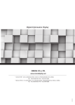
1
MAIN FRAME
ORION PDP CO.,LTD.
www.oriondisplay.net
Address: 257-6, Gongdan-dong, Gumi-si, Gyeongsangbuk-do, Korea
Tel : +82-2-6678-8533, Fax: +82-2-6678-8599
USER MANUAL
STAND UNIT | WALL UNIT
• 2010.12.14
Thank you for purchasing our MAIN FRAME.
Please read through this user's manual for safety before installing this product.
This product is manufactured for Multi LCD model only.
MLCD
Contents
ACCESSORY..............................................................................2
OPTIONAL...................................................................................2
STAND UNIT...............................................................................3
1. Safety Precaution..........................................................................4
2. Installing the stand (3*3)...............................................................6
3. Installing the MLCD.....................................................................16
4. Adjust the MLCD gap with the Adjuster...........................................19
5. Setting MLCD ID configuration and Connection (3X3). ......................20
WALL UNIT................................................................................21
1. Safety Precaution........................................................................22
2. Checking the location for installation..............................................24
3. Fixing Anchor and Bolt.................................................................25
4. Installing the Wall Bracket (3 X 3) .................................................26
5. Installing the MLCD.....................................................................37
6. Adjust the MLCD gap with the Adjuster...........................................41
SPECIFICATION. ....................................................................42
-1-
STAND UNIT
Infinitely Expandable
MLCD
ACCESSORY
STAND UNIT
¿¿MAIN FRAME Accessories
¿¿This manual describes the installation case for 3X3 sets.
¿¿There are 4 different types of stand. Please select a stand type as you need.
STAND UNIT
Infinitely Expandable
ORION PDP
STAND BRACKET
STAND FOOT
BOLT M6*70 + NUT M6 4EA
ADJUSTER
M10*50 2EA
BOLT M6*12 2EA
MAIN FRAME
FIX BRACKET UNIT
FIX BRACKET
1EABRACKET)
(FIX BRACKET
+ EXTENSION
3439.1
3528.1
Y-AXIS LINK 1EA
(MAIN FRAME
(Main
frame LINK)
link)
2910.6
Round headed
둥근머리
BOLT
M5*30L
BOLT
M5*30L
4EA 4EA
1682.0
1771.0
172.7
WALL BRACKET 2EA
ANCHOR BOLT 3/8" 4EA
BOLT M6*45 +
NUT M6 2EA
OPTIONAL
90
850.0
WALL BRACKET UNIT
850.0
Nx2
Nx3
950.0
1000.0
Nx4
Nx5
¿¿In case of NX3, NX4, or NX5 set formations, there is no stand bracket for the
top line of main frames.
However, it is designed to firmly fasten the main frames of the top line to the
main frames of the next line.
Screen size (mm)
OLM-4610
BOLT M8*15 4EA
NUT M8 4EA
STAND FOOT
600.0
407.3
172.7
90
172.7
557.3
172.7
600.0
407.3
90
User manual 1ea
600.0
600.0
507.3
90
10mm
wrench
SPANNER
1EA
1164.3
PEG 4EA
8mm 5mm 2.5mm
TOOL
SETSET
1SET
조립용
TOOL
1SET
2267.7
1746.4
2853.4
2328.5
main frame 1ea
STAND SUPPORT
-2-
6mm
allen wrench
OLM-4650
1X1
1025.7 x 579.9
1025.7 x 579.9
2X2
2051.4 x 1159.8
2051.4 x 1159.8
3X3
3077.1 x 1739.7
3077.1 x 1739.7
4X4
4102.8 x 2319.6
4102.8 x 2319.6
5X5
5128.5 x 2899.5
5128.5 x 2899.5
-3-
Infinitely Expandable
ORION PDP
1. Safety Precaution
MLCD
¿¿Please read and understand this manual fully before installation.
¿¿Please hand over this manual to customers after installation and ask to
read and keep this manual for future use.
Please install as described in this manual.
Installation of this product needs 3 or more
people.
Improper installation may cause serious injury or product
damage.
3 or more people need to work together to avoid personal injury
or product damage.
ÚÚPlease keep all the cautions and warnings for proper use of the product and prevent possible
accident or hazard.
ÚÚYou can find “CAUTION” and “WARNING” signs in this manual. Each sign has following meaning.
WARNING
If the user does not comply with this instruction, serious injuries or
death can be caused.
CAUTION
If the user does not comply with this instruction, minor injuries or
product damage can be caused.
Use enclosed accessories.
Install on the even ground or floor.
Improper accessories may not withstand the weight of the
product. It may cause safety problems.
Product installed on uneven places such as inclined places or
stairways may fall and cause personal injury or product damage.
Do not use heaters or humidifiers at the place of
installation.
Heat or vapor may cause fire, electric shock or malfunction.
Do not install the product near to sprinkler, fire
detector, high-voltage cable, power source, or
places of vibration or impact.
Make sure to disconnect before installation.
Use working gloves when you install.
If you install the product while the power cord is still connected,
it may cause electric shock or fire.
Wear working gloves to avoid any injury.
WARNING
Installation must be done by the skilled persons
designated by sales agent or dealership.
Do not install at unstable locations that cannot
withstand product weight.
Installation work can be very dangerous for inexperienced
person.
In case of weak floor or ground, product may fall and cause
injuries.
It may cause serious injury or even death.
If you need to move or replace the product,
please contact with skilled persons designated
by sales agent or dealership
Do not hang on the product and avoid severe
impact to the product.
Product may fall and cause injuries.
If users move or install the product without proper skill and
experience, it may cause safety problem.
-4-
-5-
STAND UNIT
CAUTION
Infinitely Expandable
ORION PDP
MLCD
1
Connect the Foot Stand and Stand Support together.
2
Hook the main Frame to the lower part of the Stand.
• When assembling, put the Foot Stand down to prevent it from falling.
• Assemble the Main Frame from the lower to the upper part.
• Attach the Stand Support to the upper and lower parts of the Foot Stand
• Insert the M6*70 bolt to the Main Frame and Stand Hook.
• After assembling, check if it would stand on its own.
• If the M6*70 bolt was not inserted, the Main Frame would fall or be damaged.
STAND SUPPORT
M6*70
M8 NUT
Top
STAND FOOT
M8*12L
※It is more convenient to distinguish top
and bottom, if you put the main frame as
shown in the figure to use the holes as
indicators.
After inserting M8 NUT, apply
the M8*12 bolt with the enclosed
6mm allen wrench.
-6-
Bottom
-7-
STAND UNIT
2. Installing the stand (3*3)
3
ook the 2nd main Frame at the lower hook of the center
H
frame.
• I nsert the M6*70 bolt to the Main Frame and Stand Hook.
4
Assemble the two Main Frames.
• Assemble the two Main Frames at the upper and lower parts with the M6*70 bolt using the
enclosed wrench and 5mm allen wrench.
• I f the M6*70 bolt was not inserted, the Main Frame would fall or be damaged.
M6*70
M6*70
Assemble the figure
using the enclosed
wrench and 5mm
allen wrench.
-8-
MLCD
-9-
STAND UNIT
Infinitely Expandable
ORION PDP
5
ook the 3rd Main Frame at the bottom row to the Stand
H
Hook.
6
Remove the M6*70 bolt.
• Remove the M6*70 bolts inserted at the 1st and 2nd Main Frames.
• Hook the Main Frame to the Stand Hook and assemble using a wrench and 5mm allen wrench.
• Make sure that the Main Frame is securely assembled when working.
M6*70
M6*70
Assemble the figure using the
enclosed wrench and 5mm
allen wrench.
- 10 -
- 11 -
MLCD
STAND UNIT
Infinitely Expandable
ORION PDP
7
Assemble the Main Frame at the 2nd row.
8
MLCD
Assemble the middle Main Frame at the 2nd row.
• Hook the Main Frame at the 2nd row to the upper Stand Hook.
• Hook the Main Frame at the 2nd row to the upper Hook.
• Assemble the Main Frame at the 1st row and Main Frame at the 2nd Row with the M6*70 bolts.
• Repeat the work indicated in Step No. 7 to assemble the upper and lower Main Frames and then
assemble with the adjacent Main Frame with M6*70 bolts.
M6*70
• Repeat this process to assemble the Main Frame at the 3rd row.
M6*70
Assemble the figure using the
enclosed wrench and 5mm
allen wrench.
Assemble the figure using the
enclosed wrench and 5mm
allen wrench.
- 12 -
- 13 -
STAND UNIT
Infinitely Expandable
ORION PDP
9
emove the supporting plate of both Main Frames at the
R
vertical axis.
10
• Once the supporting plate of both Main Frames at the vertical axis is removed, the brackets will
move from side to side. Move the vertical axis at both sides to install the MLCD.
both rows at the vertical axis as "Y-Axis Link" based
Fix
on the right side.
• Fix both rows at the vertical axis as "Y-Axis Link" to the right side of the Main Frame bracket for the
simultaneous movement of the vertical axis.
• Do not remove the supporting plate of the supporting axis.
� �
Fixed Cent
er Column
� �
M6*12
Remove the screws of the supporting plate
with a 5mm allen wrench. Then, remove the
plate completely from the Main Frame.
Connect the Main Frame and Y-Axis Link
with M6*12 bolts using a 5mm allen wrench.
- 14 -
MLCD
- 15 -
STAND UNIT
Infinitely Expandable
ORION PDP
Infinitely Expandable
ORION PDP
MLCD
1
2
Attach the PEG and Guide Pin to the MLCD.
Install the MLCD from the lower part of the middle set.
• Assemble the four PEGs at the back of MLCD.
• Insert the PEGs in the PEG holes.
• Install the Guide Pins where MLCD touches.
• Put the set down slowly. The panels can be damaged by impact.
• Install the MLCD from the bottom of both sides after completing the installation at the lower middle
part.
Guide Pin
There is a hole for the
installation of the
Guide
Pin at the upper part
and the sides.
7
5
ML
CD
• Mo
d
• Volt el Name
:
ag
• Cu e : AC~ OLM-46
rr
1
1
• Fre ent : Max 00 - 240 0
V
quen
.
• Ser cy : 5 3A
ial N
0/60
Hz
o:
PD
e in K P
orea
Mad
CAU
TIO
ID S
ML
CD
N
• Mo
del
• Vol Name
tage
:
• Cur : AC~10OLM-4610
rent
• Fre : Max. 0 - 240
V
que
• Ser ncy : 50/63A
ial No
0Hz
:
ELE
2
PD
e in KorP
ea
Mad
CT
CAUT
ION
ID SE
LECT
PC
PC
FAN
FAN
STB
PWR
ON
VID
EO
STB
PWR
ON
4
DVI-D
VID
EO
LAN
1
RS-23
2C
SVC
DVI-
D
LAN
RS-2
32C
SVC
PEG
M5*30
If you need to detach a MLCD set in the lower line, move
the set in the upper line to position "C". Remove guide
pins from the set in the lower line, move it to position "A"
and detach from the main frame.
Fasten 4 PEGs in the back of
MLCD with M5*30 bolts.
- 16 -
- 17 -
6
3
STAND UNIT
3. Installing the MLCD
Infinitely Expandable
ORION PDP
MLCD
3
Fix the set by pushing towards the supporting plates
The gap of the MLCD can be fixed using the Adjuster.
• Install the "FIX BRACKET unit" of both sets at the vertical axis by pushing towards the supporting
plates at the central area.
• To fix the gap detected between the MLCD or when the MLCD is tilted after the
installation, use the Adjuster.
• FIX BRACKET unit is manufactured basically for OLM-4610/OLM-4650.
The other models need to detach EXTENSION BRACKET from FIX BRACKET unit to install.
• Install the Adjuster at the lowest part of the Main Frame using the 5mm allen wrench.
Fixed
Center
Column
4
3
ADJUSTER
(M10*50)
5
8mm allen wrench
2.5mm allen wrench
※Detach EXTENSION BRACKET from FIX BRACKET unit for all
models beside OLM-4610, OLM-4650
2 1
Attach the fix bracket unit to
the main frame and fix with fixing
bolts next to MLCD handle. Use
2.5mm allen wrench.
FIX BRACKET
yyFasten the fixing bolt at
the proper position of each
MLCD model.
It is possible to lift or lower the Main
Frame using a 8mm allen wrench after the
Adjuster was installed at the lower
part of the Main Frame.
fixing bolt
- 18 -
- 19 -
STAND UNIT
4. Adjust the MLCD gap with the Adjuster.
Infinitely Expandable
ORION PDP
5. Setting MLCD ID configuration and Connection (3X3)
Configure MLCD ID and make connections for all the
necessary external devices and power.
MLCD
WALL UNIT
¿¿This manual describes the installation for 3X3 sets.
Apply following instruction according to the number of MLCD sets as you need.
• Configure MLCD ID as shown in the following figure.
• Make necessary connections such as VCR, PC and power, etc and finish configuration.
¿¿For more information for ID configuration and connection, please refer to MLCD user
manual.
IN
RS-232C
ID 4
IN
ID 5
OUT
RS-232C
ID 7
IN
OUT
OUT
ID 8
IN
OUT
40.0
IN
OUT
DVI-D
RS-232C
ID 9
MAIN FRAME
OUT
OUT
OUT
IN
IN
OUT
DVI-D
RS-232C
DVI-D
RS-232C
OUT
IN
ID 6
OUT
IN
DVI-D
IN
IN
OUT
IN
OUT
DVI-D
RS-232C
DVI-D
RS-232C
ID 3
OUT
IN
DVI-D
IN
IN
OUT
55.0
40.0
1770.6
ID 2
OUT
WALL
545.7
IN
DVI-D
RS-232C
65 50
WALL BRACKET
IN
OUT
IN
OUT
40.0
DVI Signal Distributor
(UXGA : UP TO 165MHz)
429.7
ID 1
DVI-D
223.0
545.7
RS-232C
50mm
40.0
25.0
RS-232C control PC
- 20 -
WALL UNIT
• Neatly arrange all the connection cables. If they are stretched out or disorganized, it may cause
personal injury or bad connection.
DVI
- 21 -
Infinitely Expandable
ORION PDP
1. Safety Precaution
MLCD
CAUTION
¿¿Please read and understand this manual fully before installation.
¿¿Please handover this manual to customers after installation and ask to read
and keep this manual for future use.
Please install as described in this manual.
Installation of this product needs 6 or more
skilled people.
Improper installation may cause serious injury or product
damage.
6 or more people need to work together to avoid personal injury
or product damage.
WARNING
If the user does not comply with this instruction, serious injuries or
death can be caused.
CAUTION
If the user does not comply with this instruction, minor injuries or
product damage can be caused.
WARNING
Installation must be done by the skilled persons
designated by sales agent or dealership.
Check the condition and type of wall before
installation. If all the condition fits, use enclosed
anchors and bolts.
Make sure to use the drill and bit of specified
diameter. Follow the instruction for the depth of
the hole, too.
Unauthorized anchors and bolts may not withstand the weight of
the product and may cause safety problems.
Unspecified way of drilling may cause unstable installation. It
may cause safety problems.
Do not use heaters or humidifiers at the place of
installation.
Do not install the product near to sprinkler, fire
detector, high-voltage cable, power source, or
places of vibration or impact.
Avoid weak or unstable locations.
MPDP sets may fall, if the location of installation cannot
withstand the weight of MPDP sets.
Installation work can be very dangerous for inexperienced
person.
It may cause personal injury or product damage.
It may cause serious injury or even death.
Heat or vapor may cause fire, electric shock or malfunction.
When you need to move or replace the
product after installation, contact with the
skilled persons designated by sales agent or
dealership.
Do not hang on the product or give any impact.
Product may fall and cause person injury.
Make sure to disconnect power cord before
installation.
Installation work can be very dangerous for inexperienced
person.
Use working gloves when you install.
Wear working gloves to avoid any injury.
If you install the product while the power cord is still connected,
it may cause electric shock or fire.
It may cause safety problems.
- 22 -
- 23 -
WALL UNIT
ÚÚPlease keep all the cautions and warnings for proper use of the product and prevent possible
accident or hazard.
ÚÚYou can find "CAUTION" and "WARNING" signs in this manual. Each sign has following meaning.
Infinitely Expandable
ORION PDP
2. Checking the location for installation.
Check the type of wall to examine whether it can
withstand the weight of product.
MLCD
3. Fixing Anchor and Bolt
¿¿Make sure to use specified accessory.
¿¿Check the positions and intervals.
If the hole positions are not accurate, the gap between MLCD sets can be irregular.
• Check the type and thickness of wall and the finish material.
Drill a hole with 8mm of diameter and
80mm~100mm of depth at the anchor spot
marked at the wall.
Drill
• Check the wall can withstand the weight of the product before installation.
• You can use enclosed anchors and bolts, if the thickness of the finish material is 20mm or less.
Check the installation space.
Clean the hole.
Insert the bolt into the hole.
Bolt
• Select the location suitable for the product size and install to maintain the horizontal and the vertical
position.
• Leave some space between the product and wall or other structures. (Minimum 15cm)
• If the product is installed in a closed space, it may be a cause of fire or malfunction for its internal
heat.
Insert the sleeve along the bolt.
Sleeve
Attachment
Insert the attachment, and hit it to insert by the
hammer.
Hammer
WALL BRACKET
Washer
Nut
- 24 -
Fix the WALL BRACKET and assemble the
washer and the nut.
Fasten the nut securely.
- 25 -
WALL UNIT
• Never install the product to the wall of gypsum board.
Infinitely Expandable
ORION PDP
MLCD
4. Installing the Wall Bracket (3 X 3)
2
Install the Wall Bracket.
Hook the Main Frame at the lower part of the Wall Bracket.
• Mark the location on the wall where the Bracket will be installed according to the number of set and
gap.
• Assemble the Main Frame starting from the lower to the upper part.
• To install the Wall Bracket on the lowest part of the Main Frame, choose two areas at the upper and
lower parts for each set. Install the Wall Brackets facing each other at the bottom portion.
• If the M6*70 bolt was not inserted, the Main Frame would fall or be damaged.
• Insert M6*70 bolts to the Main Frame and the Wall Bracket.
• Drill holes where the Wall Brackets will be installed using a drill and install the anchor bolts
(3/8”). Attach with Wall Brackets and nuts.
• Make sure that the horizontal and vertical lines are balanced when working.
WALL UNIT
1
1026.5mm
1026.5mm
M6*70
40mm
545.7mm
40mm
545.7mm
40mm
Top
129.7mm
40mm
※It is more convenient to distinguish top
and bottom, if you put the main frame as
shown in the figure to use the holes as
indicators.
ANCHOR BOLT
ANCHOR BOLT
Attach the anchor bolts (3/8") and Wall
Brackets into the wall.
- 26 -
Install the Wall Brackets at the bottom
facing the upper parts.)
ANCHOR BOLT (3/8")
Bottom
- 27 -
Infinitely Expandable
ORION PDP
Hook the 2nd Main Frame at the middle Wall Bracket.
• Insert M6*70 bolts at the Main Frame and Wall Bracket.
• If the M6*70 bolt was not inserted, the Main Frame would fall or be damaged.
4
Assemble the two Main Frames.
• Assemble the two Main Frames at the upper and lower parts with M6*70 bolts using a
5mm allen wrench.
WALL UNIT
3
MLCD
M6*70
M6*70
Assemble the figure using the
enclosed wrench and 5mm allen wrench.
- 28 -
- 29 -
Infinitely Expandable
ORION PDP
ook the 3rd Main Frame at the 3rd row from the bottom
H
to the Wall Bracket.
6
Remove the M6*70 bolts.
• Remove the M6*70 bolts inserted at the 1st and 2nd Main Frames.
• Hook the Main Frame to the Wall Bracket and assemble it with a wrench and 5mm allen wrench.
• Make sure that the Main Frame is securely assembled when working.
WALL UNIT
5
MLCD
M6*70
M6*70
Assemble the figure using the
enclosed wrench and 5mm allen wrench.
Assemble the figure using the
enclosed wrench and 5mm allen wrench.
- 30 -
- 31 -
Infinitely Expandable
ORION PDP
Assemble the Main Frame at the 2nd row.
8
Assemble the middle Main Frame at the 2nd row.
• Hook the Main Frame at the 1st row to the upper Hook of the Stand.
• Hook the Main Frame of the 2nd row to the Wall Bracket.
• Assemble the Main Frame at the 1st row and Main Frame at the 2nd row with M6*70 bolts.
• Repeat Step No. 7 to assemble the upper and lower Main Frames and then assemble the adjacent
Main Frame with M6*70 bolts.
• Repeat this process to assemble the Main Frame at the 3rd row.
M6*70
M6*70
Assemble the figure using the
enclosed wrench and 5mm allen wrench.
- 32 -
Assemble the figure using the
enclosed wrench and 5mm allen wrench.
- 33 -
WALL UNIT
7
MLCD
Infinitely Expandable
ORION PDP
Assemble the upper part of the 3rd row with M6*40 bolts.
• Assemble the Main Frame and Wall Bracket at the upper part and the lowest row with M6*40 bolts.
M6*40
10
emove the supporting plate of both Main Frames at the
R
vertical axis.
• Once the supporting plate of both Main Frames at the vertical axis is removed, the brackets move
from side to side. Move the vertical axis at both sides to install the MLCD.
• Do not remove the supporting plate of the supporting axis.
� �
M6*40
Fixed Center C
olumn
Remove the screws of the supporting plate
with a 5mm allen wrench. Then, remove the
plate completely from the Main Frame.
Assemble the figure using the
enclosed wrench and 5mm allen wrench.
- 34 -
- 35 -
� �
WALL UNIT
9
MLCD
Infinitely Expandable
ORION PDP
MLCD
5. Installing the MLCD
11
ix both rows at the vertical axis as "Y-Axis Link" based
F
on the right side.
• Fix both rows at the vertical axis as "Y-Axis Link" to the right side of the Main Frame bracket for the
simultaneous movement of the vertical axis.
1
Attach the PEG and Guide Pin to the MLCD.
• Assemble the four PEGs at the back of MLCD.
• Install the Guide Pins where MLCD touches.
There is a hole for the
installation of the
Guide
Pin at the upper part
and the sides.
ML
CD
• Mo
d
• Volt el Name
:
ag
• Cu e : AC~ OLM-46
rr
1
1
• Fre ent : Max 00 - 240 0
V
quen
.
• Ser cy : 5 3A
ial N
0/60
Hz
o:
PD
e in K P
orea
Mad
CAU
TIO
ID S
ML
CD
N
• Mo
del
• Vol Name
tage
:
• Cur : AC~10OLM-4610
rent
• Fre : Max. 0 - 240
V
que
• Ser ncy : 50/63A
ial No
0Hz
:
ELE
PD
e in KorP
ea
Mad
CT
CAUT
ION
ID SE
LECT
PC
PC
FAN
FAN
STB
PWR
ON
VID
EO
STB
PWR
ON
DVI-D
VID
EO
LAN
RS-23
2C
SVC
DVI-
D
M6*12
LAN
RS-2
32C
SVC
PEG
M5*30
Connect the Main Frame and
"Y-Axis Link" with M6*12 bolts
using a 5mm allen wrench.
Fasten 4 PEGs in the back of
MLCD with M5*30 bolts.
- 36 -
- 37 -
WALL UNIT
Guide Pin
Infinitely Expandable
ORION PDP
et MLCD ID and connect all the necessary external
S
devices and power.
3
Install the MLCD from the lower part of the middle set.
• Insert the PEGs in the PEG holes.
• Set ID, make necessary connections and power before hang the MLCD sets on the wall.
• Put the set down slowly. The panels can be damaged by impact.
• There is no room for such work after installation.
• Set MLCD ID as shown in the following figure.
• Install the MLCD from the bottom of both sides after completing the installation at the lower middle
part.
• Make necessary connections such as VCR, PC and power, etc one by one.
• It is easy to install the set after connecting the basic cables for the Wall Unit Type.
• Neatly arrange all the connection cables. If they are stretched out or disorganized, it may cause
personal injury or bad connection
Process the connection
of various lines when
installing MLCD.
¿¿For more information for ID setting and connection, please refer to MLCD user manual.
RS-232C
ID 1
IN
DVI-D
ID 2
OUT
IN
RS-232C
ID 4
IN
ID 7
IN
RS-232C
ID 5
OUT
ID 8
IN
RS-232C
OUT
IN
5
OUT
RS-232C
ID 9
OUT
DVI-D
IN
DVI-D
IN
IN
7
OUT
OUT
OUT
DVI-D
IN
ID 6
OUT
RS-232C
IN
OUT
DVI-D
IN
DVI-D
IN
IN
RS-232C
ID 3
OUT
OUT
OUT
DVI-D
IN
DVI-D
IN
IN
OUT
OUT
RS-232C
RS-232C
OUT
DVI-D
OUT
IN
OUT
2
4
1
6
3
DVI Signal Distributor
(UXGA : UP TO 165MHz)
If you need to detach a MLCD set in the lower line, move
the set in the upper line to position "C". Remove guide
pins from the set in the lower line, move it to position "A"
and detach from the main frame.
- 38 RS-232C control PC
- 39 DVI
WALL UNIT
2
MLCD
Infinitely Expandable
ORION PDP
MLCD
6. Adjust the MLCD gap with the Adjuster.
4
ix the set by pushing towards the supporting plates at the
F
center of the vertical axis after completing the installation
of MLCD.
• Install the Fix Bracket of both sets at the vertical axis by pushing towards the supporting plates at
the central area.
The gap of the MLCD can be fixed using the Adjuster.
• To fix the gap detected between the MLCD or when the MLCD is tilted after the
installation, use the Adjuster.
• Install the Adjuster at the lowest part of the Main Frame using the 5mm allen wrench.
• Install the "FIX BRACKET unit" of both sets at the vertical axis by pushing towards the supporting
plates at the central area.
WALL UNIT
• FIX BRACKET unit is manufactured basically for OLM-4610/OLM-4650.
The other models need to detach EXTENSION BRACKET from FIX BRACKET unit to install.
Fixed
Center
Column
ADJUSTER
(M10*50)
5
4
3
8mm allen wrench
2.5mm allen wrench
※Detach EXTENSION BRACKET from FIX BRACKET unit for all
models beside OLM-4610, OLM-4650
2 1
Attach the fix bracket unit to
the main frame and fix with fixing
bolts next to MLCD handle. Use
2.5mm allen wrench.
FIX BRACKET
yyFasten the fixing bolt at
the proper position of each
MLCD model.
It is possible to lift or lower the Main
Frame using a 8mm allen wrench after the
Adjuster was installed at the lower
part of the Main Frame.
fixing bolt
- 40 -
- 41 -
Infinitely Expandable
ORION PDP
SPECIFICATION
585.7
30.0
580.0
1026.5
Weight
MEMO
1026.5mm(W) x 585.7mm(H) x 65mm(D)
340.0
External dimension
65.0
9kg(±0.5kg)
- 42 -
- 43 -
MLCD
Infinitely Expandable
ORION PDP
MEMO
MEMO
- 44 -
- 45 -
MLCD