1
Model 2805 CATVLinx® PNS Transmitter
Product Technical Bulletin
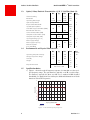
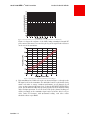
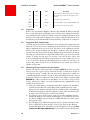
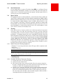
Figure 1.5 Transmitter Level per Channel vs. Log10 (Number of Channels)
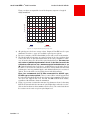
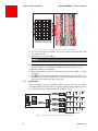
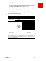
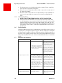
Figure 1.6 shows the response of the Model 2805 transmitter’s integral RF
power meter. This meter is accessed via pin J4-5 of the 9-pin D-sub connector
on the rear of the transmitter.
Figure 1.6 Response of Model 2805 RF Power Meter
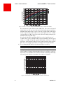
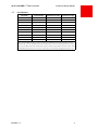
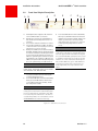
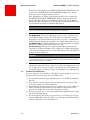
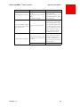
7) Each transmitter has a label such as the one shown in Figure 1.7 that gives the
RF input levels for the transmitter. The individual carrier levels should closely
match each other to ensure consistent performance on all channels. In all
cases, set the composite RF input level so that the RF INPUT LEVEL LED is
green. The RF indicator LED only operates properly for rated channel loading
and a flat input spectrum. To use the chart, look up the channel loading you
will be presenting to the transmitter input and read off the drive level per
video carrier. For instance, with 40-channel loading, each video carrier
should be about +25.0 dBmV.
Revision 1.1
5