1
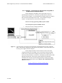
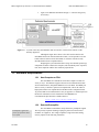
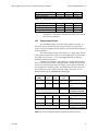
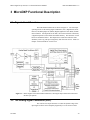
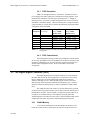
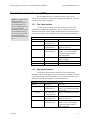
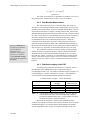
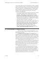
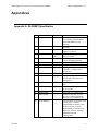
Micro Digital X-ray Processor - Technical Reference Manual
3.4.1
mdo-microDXP-MAN-1.1.2
FiPPI Decimation
FiPPI’s are distinguished also by ‘decimation’. Decimation refers to
pre-averaging of the ADC signal prior to the FPGA processing pipeline. Each
decimation accommodates a specific range of peaking times, i.e. shaping or
integration times. Up to three (3) FiPPI configuration files can be stored in the
microDXP’s nonvolatile memory. When the peaking time is changed such that
a range boundary is crossed, the host software downloads the appropriate FiPPI
configuration to the MicroDXP.
FiPPI
Decimation
#ADC Samples
in Average
0
1
2
3
4
5
6
1
2
4
8
16
32
64
Table 3.1:
Peaking Time
Range: 16MHz
Pipeline Clock
125 ns – 750 ns
250 ns – 1.5 µs
500 ns – 3.0 µs
1.0 µs – 6.0 µs
2.0 µs – 12.0 µs
4.0 µs – 24.0 µs
8.0 µs – 48.0 µs
Peaking Time
Range: 8MHz
Pipeline Clock
250 ns – 1.5 µs
500 ns – 3.0 µs
1.0 µs – 6.0 µs
2.0 µs – 12.0 µs
4.0 µs – 24.0 µs
8.0 µs – 48.0 µs
16.0 µs – 96.0 µs
Available peaking time ranges by FiPPI decimation and pipeline
clock speed.
3.4.2
FiPPI Code Variants
The FiPPI pipeline topology for RC-type preamplifiers is different than
for reset-type preamplifiers, thus two standard code variants are offered for each
decimation. Additionally, any use of the auxiliary digital I/O will require perinstance FiPPI configuration variant. Please contact XIA to discuss this
development.
3.5 The Digital Signal Processor (DSP)
The Digital Signal Processor acquires and processes event data from
the FiPPI, and controls the ASC through DACs. The processor is an Analog
Devices ADSP-2183 16 bit Fixed-Point DSP optimized for fixed-point
arithmetic and high I/O rates. Different DSP program variants are used for
different types of data acquisition and different preamplifier types. Chapter 5
describes in detail the DSP operation, its tasks, and parameters which control
them.
The ADSP-2183 has 16K words of 16-bit wide data memory and 16K
words of 24-bit wide program memory, part of which is used as data memory to
hold the MCA spectrum. (If more memory is required for special purposes, up
to 4 Mbytes of extended memory can be added by specifying option M).
Transferring data to/from these memory spaces is done through the DSP’s builtin DMA port, which does not interfere with the DSP program operation.
3.5.1
FLASH Memory
A new feature implemented on the microDXP is the inclusion of on
board non-volatile memory, which allows for firmware storage and retrieval.
8/6/2009
34