1
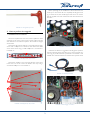
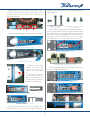
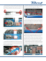
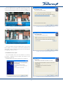
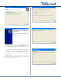
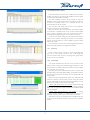
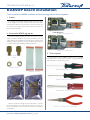
TECHNICAL NOTE #08 rev. 01 KAESOP board installation How to perform KAESOP installation and firmware upgrade in K Series amplifiers 1 Preface It is possible to install the optional KAESOP board on every K Series amplifier with serial number newer than 19062, older serial numbers will need to be sent back to Powersoft factory for an internal board change, please contact directly Powersoft for further information about. K-‐Light RFIGURE J45 board 6: K-Light RJ45 board 2 Powersoft KAESOP upgrade kit Powersoft KAESOP upgrade Kit comes as two brass spacers support standoff (FIGURE 1), two spacers (FIGURE 2), two flat cables (FIGURE 3), a KAESOP board protected in an electrostatic shielding envelope (FIGURE 4), a front panel RJ45 board protected in another electrostatic shielding envelope(FIGURE 5). K 4-‐20 RJ45 7: board FIGURE K 4-20 RJ45 board 3 Tools required FIGURE 1: Brass spacers support It is necessary to have a Phillips screwdriver PH 0, a Phillips screwdriver PH 1, an M2,5/5mm nut driver, a long needle nose solid joint pliers, an hexagonal key 2x90. FIGURE 2: Spacers FIGURE 8: Phillips PH0 screwdriver FIGURE 9: Phillips PH1 screwdriver FIGURE 10: M2, 5/5mm nut driver FIGURE 3: Flat cables FIGURE 4: KAESOP board FIGURE 5: RJ45 board Please be careful in ordering the correct kit: there is a specific kit named KT66 for K4 to K20 while kit KT68 is for K2 and K3, where the difference is in the RJ45 board showed in FIGURE 6 and FIGURE 7. © 2012 - 2013 Powersoft powersoft_TN008_KAESOPInstallation_en_v1.0 FIGURE 11: Long needle nose solid joint pliers Keep This Technical Note For Future Reference Before operating for the installation of the K-DSP board it is necessary to check if the rails are completely discharged: leds in fig. 15 should be off, this should happen after about 15 minutes that the amplifier has been switched off and disconnected from the mains. FIGURE 12: Hexagonal key 2x90 7 rail led is need cap 4 How to perform the upgrade 1.1 KAESOP hardware installation Disconnect amplifier from the mains, if the amplifier has been connected to the mains in the last few minutes please proceed with attention as the internal capacitors bank could be charged and harmful! Remove the side support steel bars, unscrewing the four bigger screws with a Phillips PH1 screwdriver, then remove the three screws in the centre using a smaller Phillips PH 0 screwdriver as in FIGURE 13. FIGURE 15: Rail leds If the leds are still on it is suggested to discharge the capacitors bank by connecting a lamp of at least 40 W / 230 V, best if 60 W / 230 V (fig. 16) to the connectors positioned as on FIGURE 17 and FIGURE 18 to avoid harmful current stored in the capacitors bank. FIGURE 13: Amplifier side view, screws Remove the amplifier cover unscrewing the nine screws (four in the front, two in the centre and three in the rear) using a screwdriver Phillips PH 0 as in FIGURE 14. FIGURE 16: Dummy load lamp FIGURE 14: Amplifier top view, screws FIGURE 17: Discharging connectors 2 K-Light (K2-3) and K-Series (K4-20), those are showed in FIGURE 24 and FIGURE 25. Keeping a leg of the dummy load on one of the two “GND” connectors, first touch with the other leg one of the right “+VCC” connectors, and then one of the left “-VCC” connectors (as showed in FIGURE 18). 16 K-‐light (K2-‐3) black metal FIGURE 24: K-light (K2-3) cover screws metal cover screws 17 K-‐Series (K4-‐20) black metal cover screws FIGURE 25: K-Series (K4-20) metal cover screws Once removed the black metal cover (FIGURE 26, FIGURE 27), remove the original RJ45 circuit (every K/K Light amplifier has a RJ45 board, without leds on the RJ45 plugs, that should be substituted with the new one provided together with the KAESOP kit) by unscrewing the black screw here and the brass spacer support standoff, keep them as you will need them to fix the new circuit. FIGURE 18: Detail of discharging connectors Open the front panel left grid removing the screw as in FIGURE 19. 11 Front panel not upgraded KAESOP, screw to remove to open FIGURE 19: Frontto panel grid screw 18 Black etal cover removed FIGURE 26:mMetal cover removed FIGURE 20: Left grid open FIGURE 27: RJ45boriginal removed 19 RJ45 original oard board removed Once the left grid is open (FIGURE 20), remove the screw to detach the front panel left “ear” as in FIGURE 21. The next step is to remove the dust filter and the the black metal cover in front of the RJ45 board as showed in FIGURE 22 and FIGURE 23. FIGURE 28: Front panel without original board FIGURE 21: Left ear screw FIGURE 22: Dust filter removed 14 Black metal cover and screws to remove, dust filter and cover once removed Once the original RJ45 board has been removed fit the two flat cables as in FIGURE 28 to FIGURE 30. 20 Front panel without original RJ45 board FIGURE 29: Flat cable inserted, front view 21 Flat cable inserted 15 Black metal cover removed FIGURE 23: Metal cover removed Please pay attention that the screws that are holding in place the black metal cover in front of the RJ45 board are different in FIGURE 30: Flat cable inserted, top view 22 Flat cable inserted, top view 3 Once the flat cables are inserted, position the new RJ45 board using the same black screw and brass spacer support standoff that were keeping the original RJ45 board in place, just set the two spacers between the RJ45 board and the front panel (FIGURE 31). Locate the control board (or the DSP board if installed), positioned in the front left corner of the amplifier (FIGURE 35) and remove the screws with a Phillips PH0 screwdriver. FIGURE 31: RJ45 board with screw and spacers in position 23 RJ45 board with screw and spacers in position Then fix the panel (FIGURE 32). FIGURE 35: Screws of the control board (or DSP board) Screw on the same holes the brass spacers support standoff coming with the KAESOP kit. Be careful in both removing the screws and positioning the brass spacers support standoff: help yourself with a long needle nose solid joint pliers for avoiding any piece to fall under control board. FIGURE 32: RJ45 board positioned 24 RJ45 board in position Now fix the flat cables to the two red plugs as in FIGURE 33. FIGURE 36: Brass spacers in place KAESOP board can be positioned directly on top of the control board or on top of the DSP board if fitted but do not remove control board from the amplifier...it will not work without it! Once the KAESOP board is on top of the control board (or of the DSP board if it’s installed in the amplifier), pay particular attention to the four connectors of both boards, they have to mate perfectly, do not press the board until you’re sure that connectors are exactly in position or it’s possible to damage the amplifier! Plug the KAESOP board on the control board (or K-DSP) and secure it back on the two brass spacers support standoff, using the two screws previously removed. Do not to tight them too much or you could brake the brass spacers supports. FIGURE 25 33:flat Flatcables cables fitted RJ45 circuit fitted on on RJ45 circuit The flat cables are equally long but since one has to travel a lower distance it must be bend in order to avoid possible damage when the cover will be placed back. Please look at FIGURE 34 and verify that the abundance of the lower cable is folded between the RJ45 circuit and the front panel. FIGURE 37: KAESOP board correctly positioned FIGURE 34: Lower cable bent 4 26 Lower flat cable bended between RJ45 circuit and front panel 29 KAESOP board correctly positioned Once the KAESOP board is in position it’s necessary to connect the two flat cables: the lower, folded one should be plugged in the second horizontal red plug from the top of the board (FIGURE 38). FIGURE 41: Firmware updater installation, step 2 FIGURE 38: Lower flat cable plugged-in 30 First flat cable wired The longer one must be inserted on the top plug, as in FIGURE 39. FIGURE 39: Top flat cable plugged-in 31 Both flat cables wired Now it is possible to close the amplifier with its cover, screw it back in position, as it is possible to screw back in position the two side support steel bars, following the reverse process described at the beginning of this document. FIGURE 42: Firmware updater installation, step 3 1.2 KAESOP Firmware update Once the KAESOP board has been installed it is necessary to perform a KAESOP firmware update, the software can be requested to Powersoft. Install procedure is showed in FIGURE 40 to FIGURE 44. FIGURE 43: Firmware updater installation, step 4 FIGURE 40: Firmware updater installation, step 1 5 FIGURE 46: KAESOP Firmware update, step 1 FIGURE 44: Firmware updater installation, step 5 FIGURE 47: KAESOP Firmware update, step 2 FIGURE 45: Firmware updater installation, step 6 The Powersoft Firmware Updater utility can be used to update the KAESOP board firmware with an easy guided procedure. The software can update an unlimited number of amplifiers in a parallel manner, taking just a couple of minutes for completing the operation. Connect the PC to the same ethernet network of the amplifiers, launch the Firmware updater software and follow the steps as in FIGURE 46 to FIGURE 51. FIGURE 48: KAESOP Firmware update, step 3 6 1.3 Amplifier firmware update Once the KAESOP board has been installed and its firmware updated it is necessary to perform the amplifier firmware update to disclose the full KAESOP capabilities. The older amplifier firmware release needed to have the KAESOP working in Powersoft Power Control Manager software is version 3.13.7, while version 4.1.0 is required to have it in Armonìa software remote control. This procedure will update the firmware of the KFRONT, KCNTRL and KDSP board (if installed). Before to perform the firmware update check if the amplifier is connected to a reliable power source, an UPS (uninterruptible power supply) is suggested (never use the Powersoft Hub for powering the amplifier during firmware updates procedure!). In case of mains failure during firmware update the procedure needs to be re-started, switching off and back on the amplifier, anyway no damage will occur to the amplifier if firmware update fails for any reason. Do not remove firmware smart card during update procedure, always wait until amplifier has completed the update. FIGURE 49: KAESOP Firmware update, step 4 1.3.1 First step Check current firmware versions to avoid downgrading the unit. Go to MenuSetupHardware Info, scroll trough the screens and write down versions, comparing them against those of the smartcard and KAESOP. 1.3.2 Second step Turn off the amplifier, insert the FW smart card into the slot (electric contacts facing down) while keeping pressed the first and second buttons on the left of the front panel; turn on the amplifier and wait about 3 to 6 seconds. Soon after the fan test (full throttle blow), after 5 seconds that the yellow leds on the panel will be blinking, it is possible to release the two front panel buttons, KFRONT firmware update will start automatically. Please note that during KFRONT update the yellow leds will continue to blink for about another minute, during this period the LCD display will remain blank because the KFRONT is under update and is unable to write on the LCD display. If KDSP (DSP optional board) is installed: KDSP update will begin after KFRONT update will be completed, showing “Updating KDSP” with a progress bar. After a few minutes, the KDSP update will be completed. If KDSP (DSP optional board) is not installed: a warning message (“START ERROR” or “KDSP board not present”) is displayed, requiring a button press confirmation to proceed. Wait about 3 minutes (10 minutes if KDSP is installed), the time necessary for the KFRONT, KCNTRL and KDSP microcontrollers update. FIGURE 50: KAESOP Firmware update, step 5 FIGURE 51: KAESOP Firmware update, step 6 7 1.3.3 Third step When the message “Do you want to update SHARC DSP?” is displayed, press YES push-button. Only if KDSP board is installed, the SHARC processor firmware update will be activated and it will last about 20 minutes. Upon concluding, a message “ Firmware update completed, press OK to restart” will indicate that the procedure has been successfully completed, before restarting the amplifier please remove the firmware card. 1.3.4 Fourth step Verify the result of the firmware update procedure. Turn on the amplifier, go to Menu=>Setup=>Hardware Info and read the version numbers. All installed boards must have the same version number, and the SHARC firmware version must be the same written on the smartcard label. For example: KFRONT:4.0.2-34 KCNTRL:4.0.2-34 KDSP:4.0.2-2000 KAESOP:4.0.2-5 FW version is 4.0.2. The last number on each line (after the hyphen) is the build count (meaningless) except for the KDSP board. For the KDSP the last 4 digit number after the hyphen represents the SHARC firmware version (here it is 2000). If something is mismatching, please check the smartcard version and the KAESOP file version matching, then retry the entire procedure from the beginning. Please remember that if firmware update process stops before completion (for mains drop or any other problem), it is necessary to start it again from the beginning (switching the amplifier off and back on), as it could happen that 2 different firmware versions are present in the amplifier different boards, causing possible problems to the amplifier itself. 8 Via Enrico Conti, 5 50018 Scandicci (FI) Italy Tel: +39 055 735 0230 Fax: +39 055 735 6235 General inquiries: [email protected] Sales: [email protected] Application & technical support: [email protected] Service & maintenance: [email protected] www.powersoft-audio.com © 2012 - 2013 Powersoft powersoft_TN008_KAESOPInstallation_en_v1.0